

Broadata Communications 1200E User Manual
1200E Series
FIBER OPTIC
SERIAL DIGIT AL AUDIO TRANSPORT SYSTEM
BCI reserves the right to make changes to the products described herein without
prior notice or consent. No liability is assumed as a result of their use or
application. All rights reserved.
©2005 Broadata Communications, Inc.
Fiber Optic Serial Digital Audio Transport System
BCI 1200E User’s Manual
SAFETY INSTRUCTIONS AND
COMPLIANCE DECLARATIONS
PLEASE OBSERVE THE FOLLOWING SAFETY
PRECAUTIONS AS OUR PRODUCTS CONT AIN
CLASS I LASER PRODUCTS
WARNING
Do not disconnect the fiber optic connector while the unit is powered
up. Exposure to laser radiation is possible when the laser fiber optic
connector is disconnected while the unit is powered up.
Although the fiber optic connectors in this product emit only Class 1
energy that is below the levels considered to be hazardous, one should
never stare directly into a fiber optic connector or an unconnected fiber
end unless one can be certain that no exposure to laser energy could
occur.
CAUTION
This manual is intended for use by trained service personnel. The use
of controls, making adjustments, or performing operations other than
those specified may result in hazardous radiation exposure.
The following label or equivalent is located on the surface of laser products.
This label indicates that the product is classified as a CLASS 1 LASER
PRODUCT.
CLASS 1 LASER PRODUCT
SURGE PROTECTION DEVICE RECOMMENDED
This product contains sensitive electrical components that may be
damaged by electrical spikes, surges, electric shock, lightning strikes,
etc. Use of surge protection systems is highly recommended in order
to protect and extend the life of your equipment.
Broadata Technical Support, CustomerService@Broadatacom.com
3

BCI 1200E User’s Manual
Fiber Optic Serial Digital Audio Transport System
TABLE OF CONTENTS
1.0 PRODUCT DESCRIPTION .............................................5
2.0 SETUP..............................................................................7
2.1 CABLING AND CONNECTORS ..................................... 8
2.1.1 ELECTRICAL CABLE CONNECTION ........................8
2.1.1.1 AUDIO CONNECTION ............................................... 8
2.1.2 OPTICAL FIBER CONNECTION...............................11
2.2 POWER CONNECTION ................................................ 13
3.0 OPERATION...................................................................13
4.0 MAINTENANCE AND TROUBLESHOOTING .............. 14
4.1 MAINTENANCE .............................................................14
4.2 TROUBLESHOOTING ..................................................14
5.0 SPECIFICATIONS..........................................................16
6.0 SERVICE PROCEDURE ............................................... 18
6.1 REPLACEMENT POLICY .............................................18
6.2 RETURN AND REPAIR SERVICE.................................18
7.0 LIMITED WARRANTY....................................................19
4
Broadata Technical Support, (800) 214-0222

Fiber Optic Serial Digital Audio Transport System
BCI 1200E User’s Manual
1.0 PRODUCT DESCRIPTION
The 1200E Series is a high performance, yet affordable, Fiber Optic
Serial Digital Audio Transport System. The standard 1200E system is
designed to transport four (4) or eight (8) channel AES/EBU serial digital
audio signals over long distance through either singlemode or multimode
fiber. The 1200E design accepts synchronous or asynchronous AES/EBU
channels of 44.1 or 48 kHz frequency and many versions of optical
transmitter and receiver combinations are available to address different
distance requirements.
Because of the use of advanced digital fiber optic transmission technology ,
no user adjustments are required in the 1200E system, enabling quick
setup and trouble-free operation. The 1200E is designed for compliance
with AES3-1992 (ANSI S4.40-1992, IEC 958), a standard format and
protocol for serial transmission of digital audio.
The 1200E comes with two packaging options: a rugged, standalone,
and compact unit, or a plug-in card for a card cage system. Panel
connectors are provided for digital serial audio (terminal block connector)
and fiber connection (FC-type for the singlemode version, or ST-type for
the multimode version). The 1200E can be easily monitored by front
panel LED indicators for power, optical link, and channel activity .
Broadata Technical Support, CustomerService@Broadatacom.com
5
BCI 1200E User’s Manual
1208E-R
+
+
+
+
4
3
1204E-T
4
2
1
PWR
2
12VDC
TX
I N P U T S
+
+
+
+
3
4
1204E-R
3
1
2
1
LINK
PWR
12VDC
RX
O U T P U T S
+
+
+
+
1208E-T
+
+
+
+
Fiber Optic Serial Digital Audio Transport System
TX
I N P U T S
112
334
LINK
_
_
+
+
v
v
2
1
PWR
O U T P U T S
RX
LINK
PWR
765
8
321PWR
4
1208E-R
765
8
312PWR
4
1208E-T
RX
TX
221
_
_
+
+
v
v
2
1
5
6
_
_
+
+
v
v
1
51
6
_
_
+
+
v
v
_
_
+
+
v
v
3
_
+
v
3
7
_
+
v
7
_
+
v
12VDC
4
1204E-T
443
_
+
v
12VDC
4
1204E-R
8
O
U
T
_
+
v
P
U
12VDC
T
1208E-R
S
423
8
I
N
P
_
+
v
U
T
12VDC
S
1208E-T
423
VGA
+
-
____
_ _ _
12 VDC
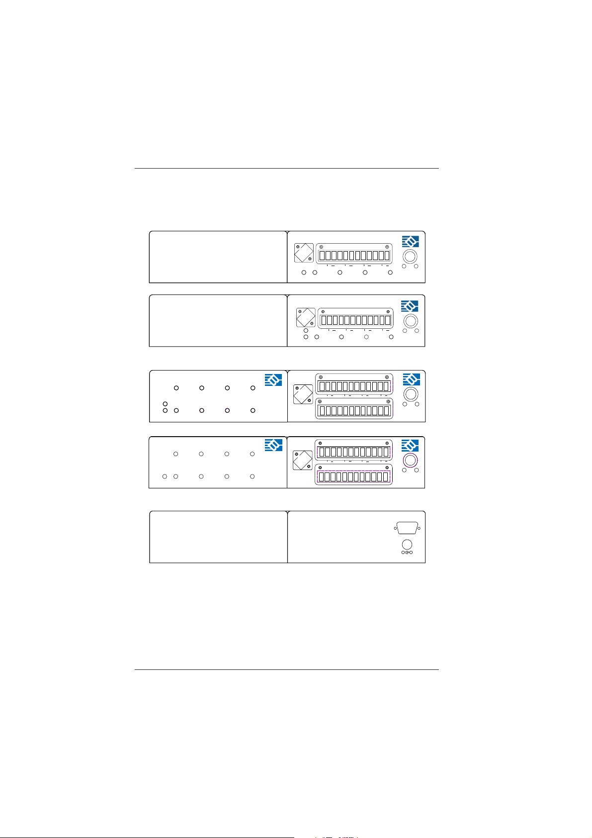
Figure 1-1
1200E Front/Rear Panels
6
Broadata Technical Support, (800) 214-0222
Fiber Optic Serial Digital Audio Transport System
BCI 1200E User’s Manual
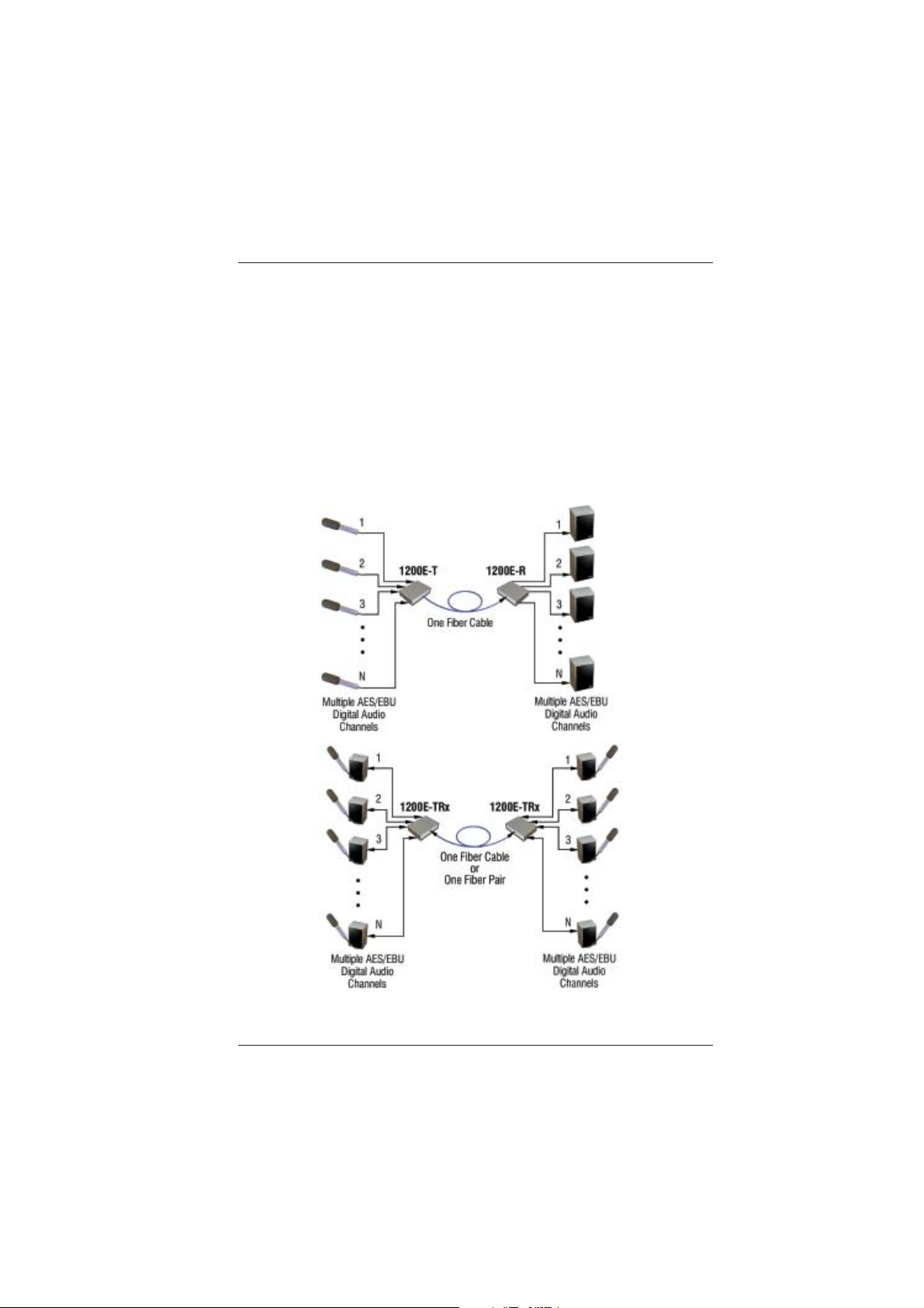
2.0 SETUP
The BCI 1200E Series units are used in pairs. In a bi-directional
application, one 1200E transceiver unit is located at the near-end and
connected through two optical fibers to an identical 1200E transceiver
located at the far end of the link. Each unit provides a separate electrical
interface connector for each audio channel. Connections are one to
one between both units. In a unidirectional application, a 1200E
transmitter (1200E-T) is located at the near-end and connected through
one fiber to a 1200E receiver (1200E-R) located at the far-end. Figure 2-1
depicts a typical installation.
Figure 2-1
1200E Setup
Broadata Technical Support, CustomerService@Broadatacom.com
7
 Loading...