

Page 1
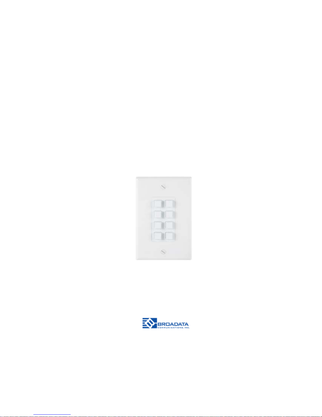
LB-KP8E
LINK BRIDGETM 8-BUTTON
WALL PLA TE ETHERNET CONTROLLER
BCI reserves the right to make changes to the products described herein without
prior notice or consent. No liability is assumed as a result of their use or
application. All rights reserved.
©2013 Broadata Communications, Inc.
Page 2

LB-KP8E User Manual
Link Bridge
TM
8-Button Wall Plate Ethernet Controller
Broadata Technical Support, [email protected]
3
SAFETY INSTRUCTIONS AND
COMPLIANCE DECLARATIONS
PLEASE OBSERVE THE FOLLOWING SAFETY
PRECAUTIONS
SURGE PROTECTION DEVICE RECOMMENDED
This product contains sensitive electrical components that may be
damaged by electrical spikes, surges, electric shock, lightning strikes,
etc. Use of surge protection systems is highly recommended in order
to protect and extend the life of your equipment.
Page 3

LB-KP8E User Manual
Link Bridge
TM
8-Button Wall Plate Ethernet Controller
Broadata Technical Support, (800) 214-0222
4
TABLE OF CONTENTS
1.0 PRODUCT DESCRIPTION .............................................5
2.0 OPERATION CONTROLS AND FUNCTIONS ............... 6
2.1 FRONT PANEL ................................................................6
2.2 REAR P ANEL ...................................................................7
2.3 TELNET COMMANDS .................................................... 8
2.4 TELNET CONTROL ........................................................ 9
2.5 WEBGUI CONTROL ......................................................10
2.5.1 MACRO SETTINGS ..................................................... 11
2.5.2 EXTENSION MACRO .................................................. 14
2.5.3 COMMAND SETTINGS ...............................................15
2.5.4 DEVICE SETTINGS..................................................... 16
2.5.5 KEY SETTINGS ........................................................... 17
2.5.6 SCHEDULE .................................................................. 18
2.5.7 NETWORK SETTINGS ...............................................21
2.5.8 SYSTEM SETTINGS ...................................................21
2.5.9 TIME SETTINGS .........................................................22
4.0 MAINTENANCE AND TROUBLESHOOTING .............. 23
4.1 MAINTENANCE .............................................................23
4.2 TROUBLESHOOTING ..................................................23
5.0 SPECIFICATIONS ..........................................................25
6.0 SERVICE PROCEDURE ...............................................26
6.1 REPLACEMENT POLICY .............................................26
6.2 RETURN AND REPAIR SERVICE.................................26
7.0 LIMITED WARRANTY....................................................27
Page 4

LB-KP8E User Manual
Link Bridge
TM
8-Button Wall Plate Ethernet Controller
Broadata Technical Support, [email protected]
5
1.0 PRODUCT DESCRIPTION
The LB-KP8E wall plate control system box is a useful design for system
installers and smart home users. With 8 direct macro command buttons
and extra 8 macro commands in WebGUI control, which allows up to 16
commands to be executed within one push and a total of 128 command
capacity inside this box, that can bring out a set of scenes in seconds.
Soft and colorful LED design fitting all environmental purposes, and PoE
(Power over Ethernet) function ease power supply issue without extra
DC power burden. Further, relay output design and scheduling function
control settings can trigger a master switch or any main switch of the
installation environment that brings the world of control to life.
Features
• 1-gang wall plate Ethernet controller with 8 buttons
• Extra virtual buttons are available via WebGUI configuration
• Comes with relays to control peripheral device on/off
• Available with PoE function or DC power supply selection
• Supports T elnet or W ebGUI control
• Supports scheduling control and settings
• Adjustable LED dim light in keypad buttons
Page 5
LB-KP8E User Manual
Link Bridge
TM
8-Button Wall Plate Ethernet Controller
Broadata Technical Support, (800) 214-0222
6
2.0 OPERATION CONTROLS AND FUNCTIONS
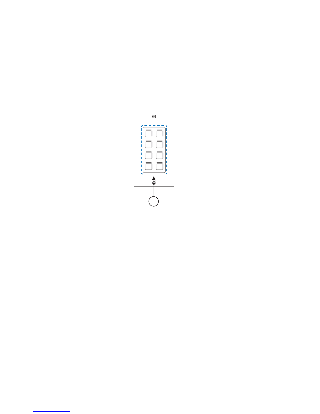
2.1 Front Panel
1. 1-8 Macro Buttons: Each button has 2 colors of LEDs adjustable
from dim 0~100% and can have up to 16 commands. Further
detail settings can be found in Section 2.5.
1
Page 6
LB-KP8E User Manual
Link Bridge
TM
8-Button Wall Plate Ethernet Controller
Broadata Technical Support, [email protected]
7
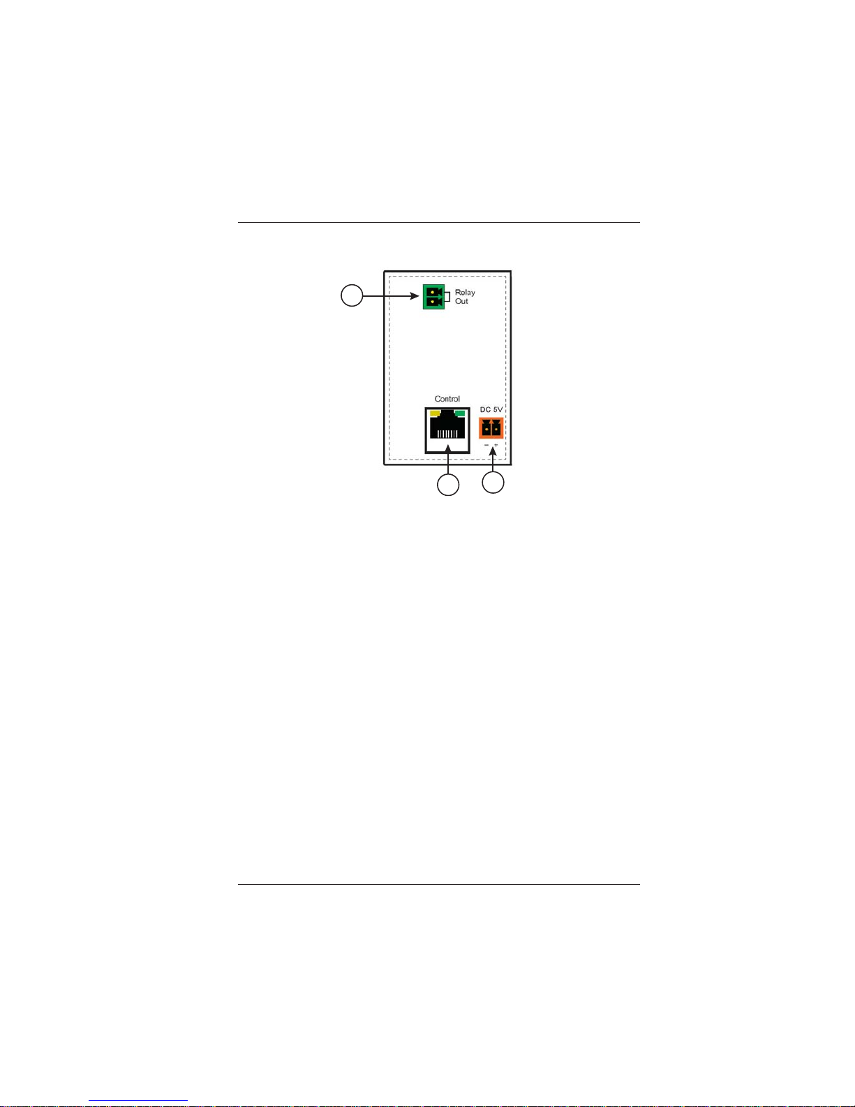
2.2 Rear Panel
1. Relay Out: Connect with device that supports DC 0~24V/5A
power or signal that supports relay function.
2. Control: Connect from PC/Laptop with active internet service
or T elnet or W ebGUI control with RJ-45 terminated cable. This
slot supports PoE PD 48V function which means when the
connected server/Hub support PSE 48v it can be powered
without DC supply connection.
3. DC 5V : Plug the 5V DC power adaptor included in the
package and connect to AC wall outlet for power supply .
1
2
3
Page 7
LB-KP8E User Manual
Link Bridge
TM
8-Button Wall Plate Ethernet Controller
Broadata Technical Support, (800) 214-0222
8
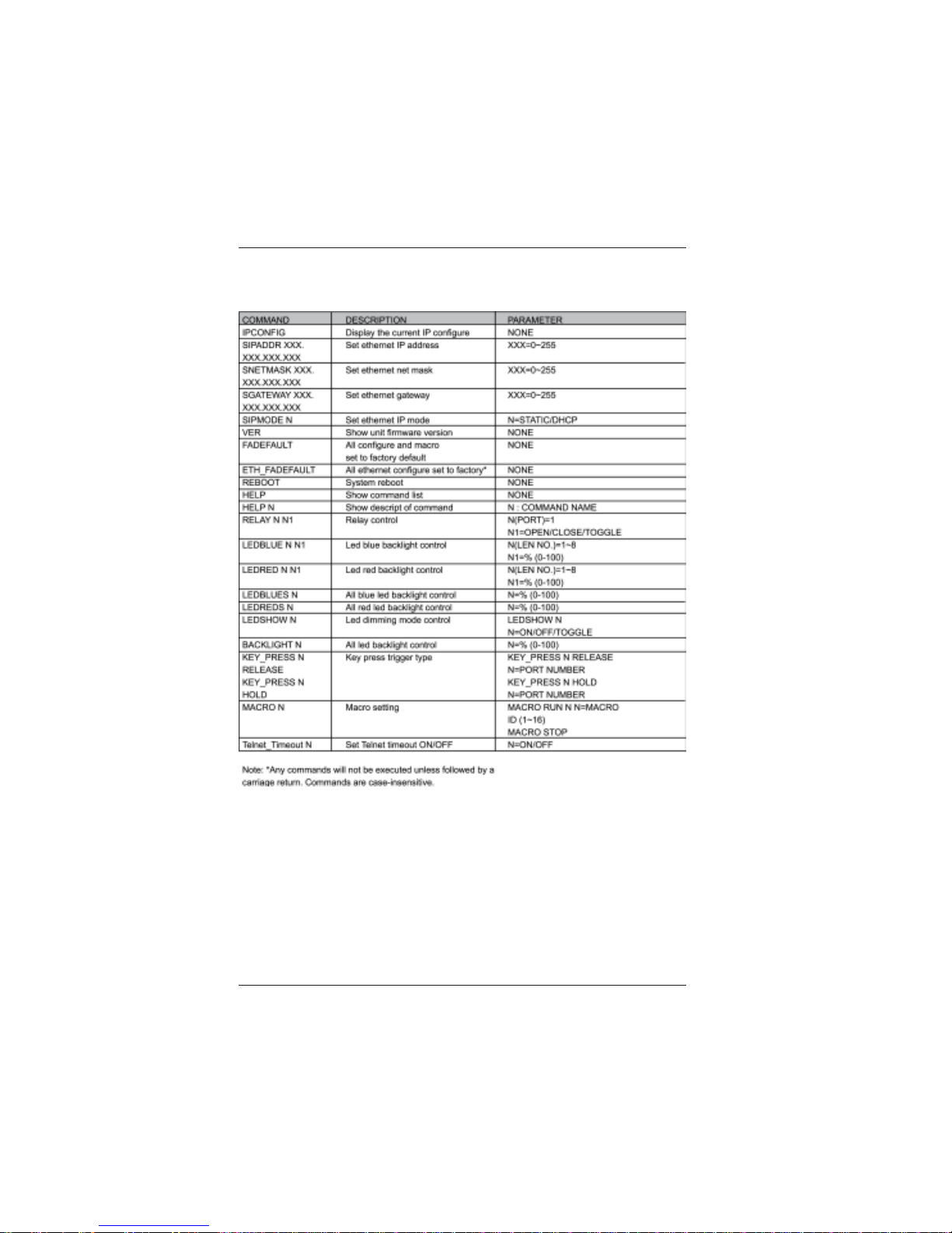
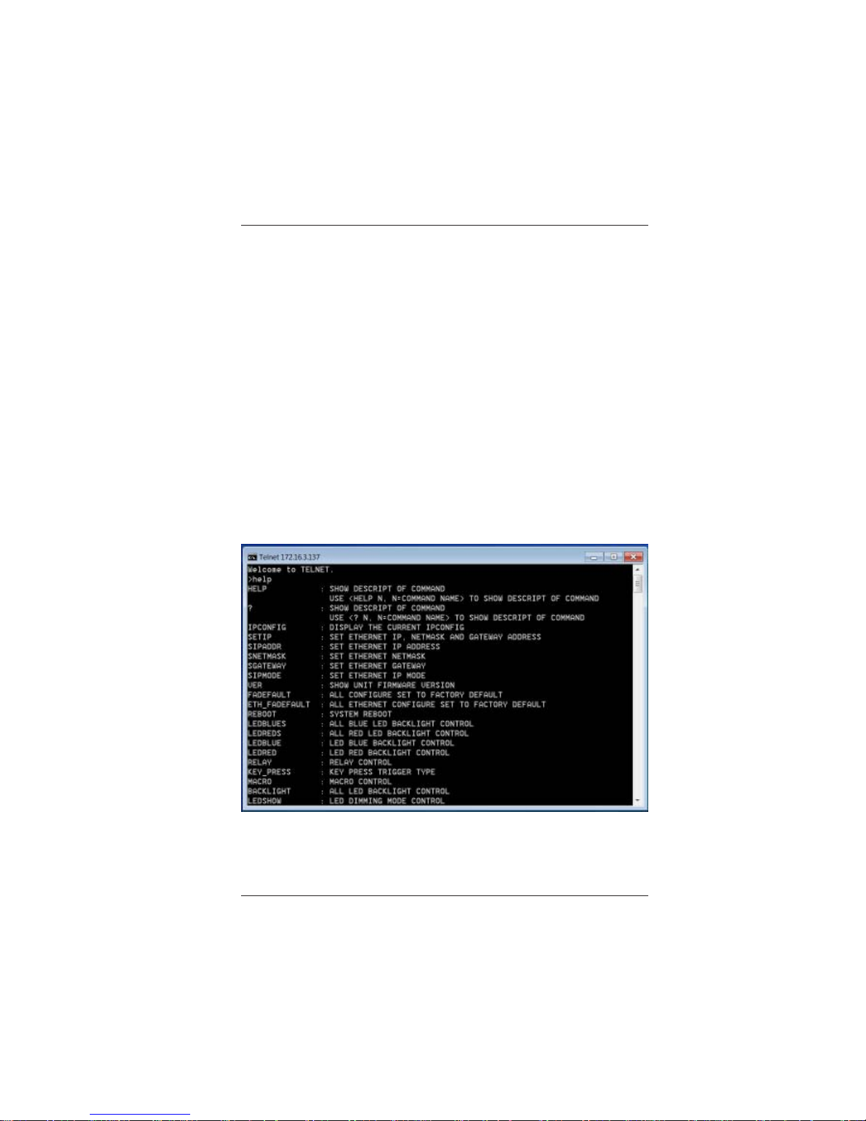
2.3 Telnet Commands
Page 8
LB-KP8E User Manual
Link Bridge
TM
8-Button Wall Plate Ethernet Controller
Broadata Technical Support, [email protected]
9
2.4 Telnet Control
Before attempting to use the T elnet control, please ensure that
both the device under control and the PC/Laptop are connected
to the same active networks.
To access the Telnet control in Windows 7, click on the ‘Start’
menu and type “cmd” in the Search field then press enter.
Under Windows XP go to the ‘St art’ menu and click on “Run”,
type “cmd” with then press enter.
Once in the command line interface (CLI) type “telnet”, then the
IP address of the unit, then hit enter.
This will bring us into the unit which we wish to control. Type
“help” to list the available commands.
Note: Commands will not be executed unless followed by a carriage
return. Commands are case-sensitive. If the IP is changed then the IP
Address required for T elnet access will also change accordingly .
Page 9
LB-KP8E User Manual
Link Bridge
TM
8-Button Wall Plate Ethernet Controller
Broadata Technical Support, (800) 214-0222
10
2.5 WebGUI Control
On a PC/Laptop that is connected to an active network system,
open a web browser and type device’s IP address on the web
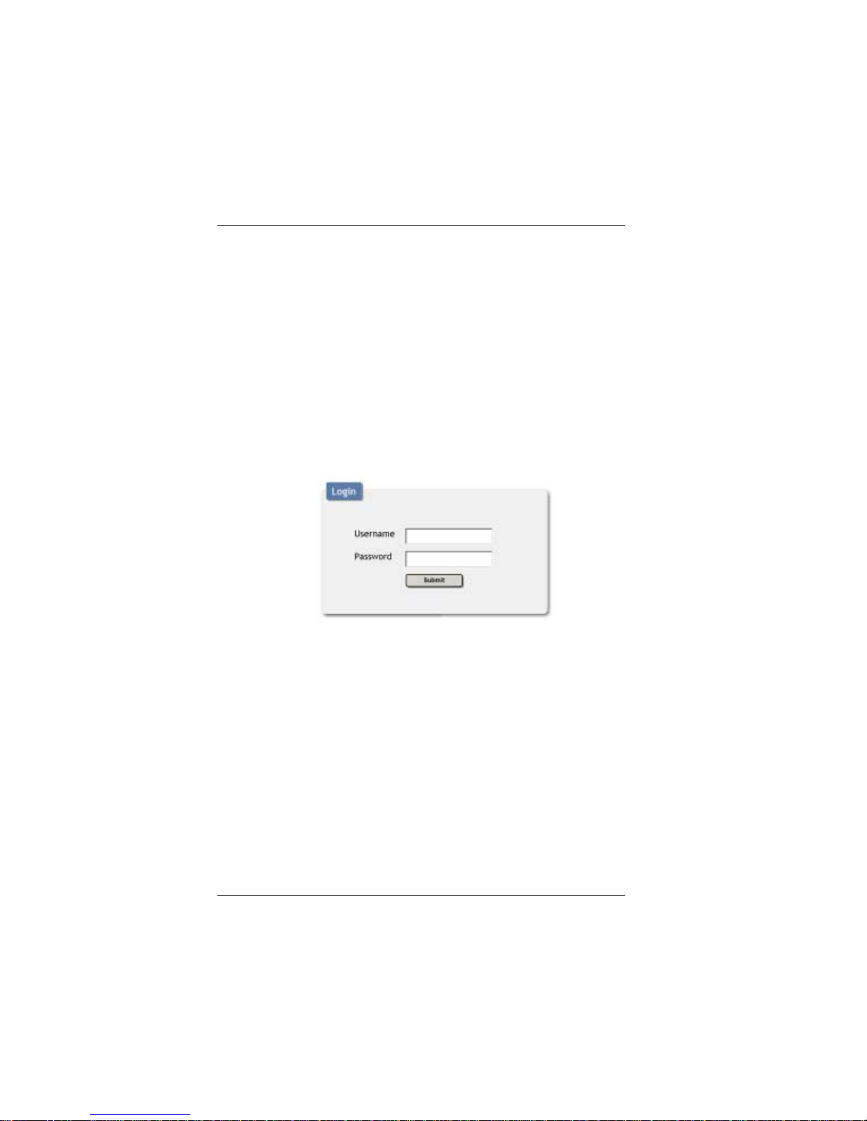
address entry bar. A security page will appear to ask for User
and Password, please key in “admin” for both to enter.
Note: The Default IP setting is DHCP.
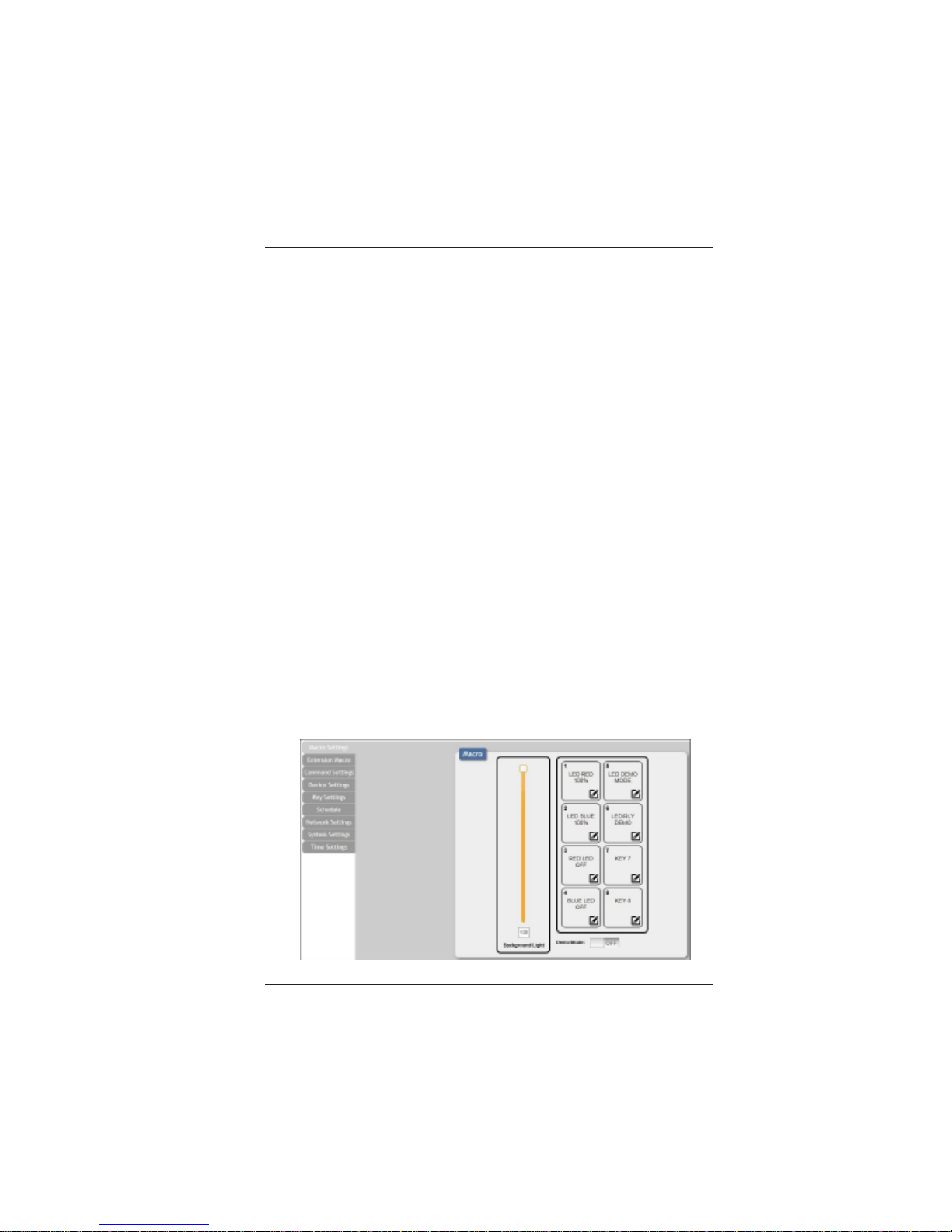
The browser will display the device’s Macro Setting, Extension
Macro, Command Settings, Schedule, Network and System
Settings pages for users to control.
Page 10
LB-KP8E User Manual
Link Bridge
TM
8-Button Wall Plate Ethernet Controller
Broadata Technical Support, [email protected]
11
2.5.1 Macro Settings
The Background Light Bar allows user to instantly change the
LEDs lighting percentage based on the orignial illumination
setting.
There are 6 Macros pre-configured as default setting for testing
the Wall-Plate Control System’s functionality. Click on Macro
1~6 to demonstrate the function of lighting LEDs.
• Macro 1: Light up the Red backlight LED with 100% brightness
sequentially from 1~8 with every 500ms.
• Macro 2: Light up the Blue backlight LED with 100%
brightness sequentially from 1~8 with every 500ms.
• Macro 3: Switch off all the read backlight LED with 0%
brightness.
• Marco 4: Switch off all the blue backlight LED with 0%
brightness.
• Marco 5: LED show mode toggle, swith off Demo Mode
• Macro 6: Light up the Blue backlight LED with 10% brightness,
Switch off all the blue backlight LED with 0% brightness,
switch Off & On Relay 1 with delay of 1000ms.
T o disable default testing mode, set Demo Mode switch to of f.
Page 11
LB-KP8E User Manual
Link Bridge
TM
8-Button Wall Plate Ethernet Controller
Broadata Technical Support, (800) 214-0222
12
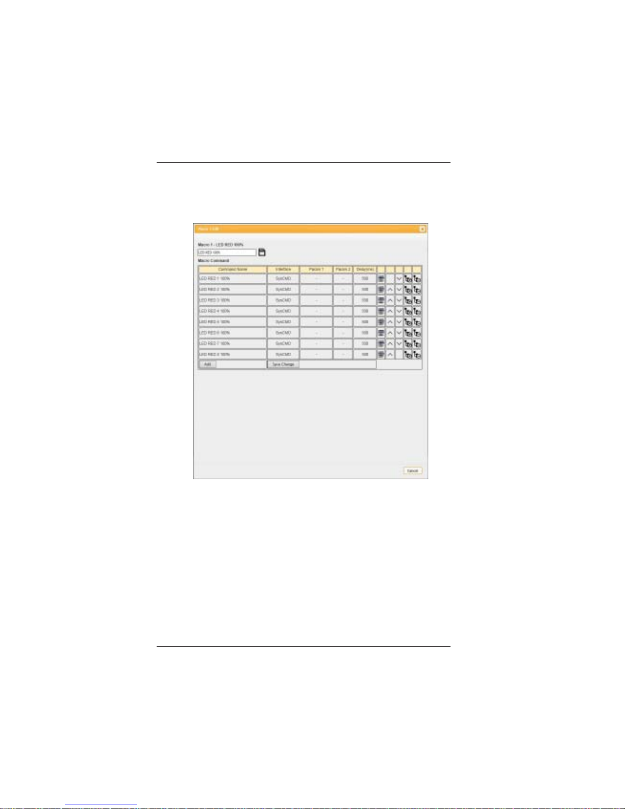
Click on the edit symbol to edit command settings. Up/down
arrows are to move the command up or down and delete button
is to delete the command.
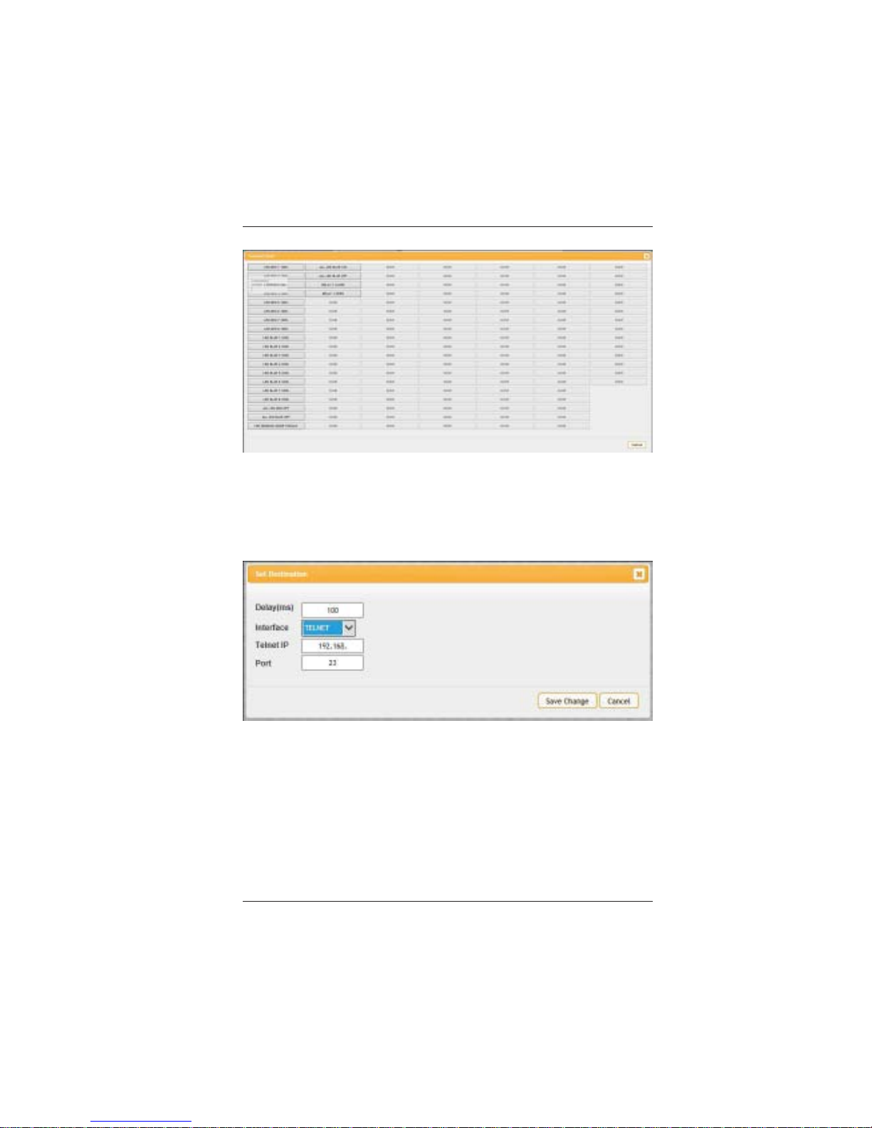
Click on Insert button/Add to insert commands. Command can
be set to control the Wall-Plate Control Box/SysCMD, other
devices connected within the same T elnet system/Internet area
and Relay devices connected through the Relay outputs of WallPlate Control Box with delay time. It is suggested the delay
time is >100ms once the setting is confirmed, double click on
Save Change.
Page 12
LB-KP8E User Manual
Link Bridge
TM
8-Button Wall Plate Ethernet Controller
Broadata Technical Support, [email protected]
13
Command set to control the device within the same telnet
system or internet area require to set its IP and Port number
and it is strongly recommand to set the delay time>500ms in
order to secure a successful command sending. Once the setting
is done click on Save change.
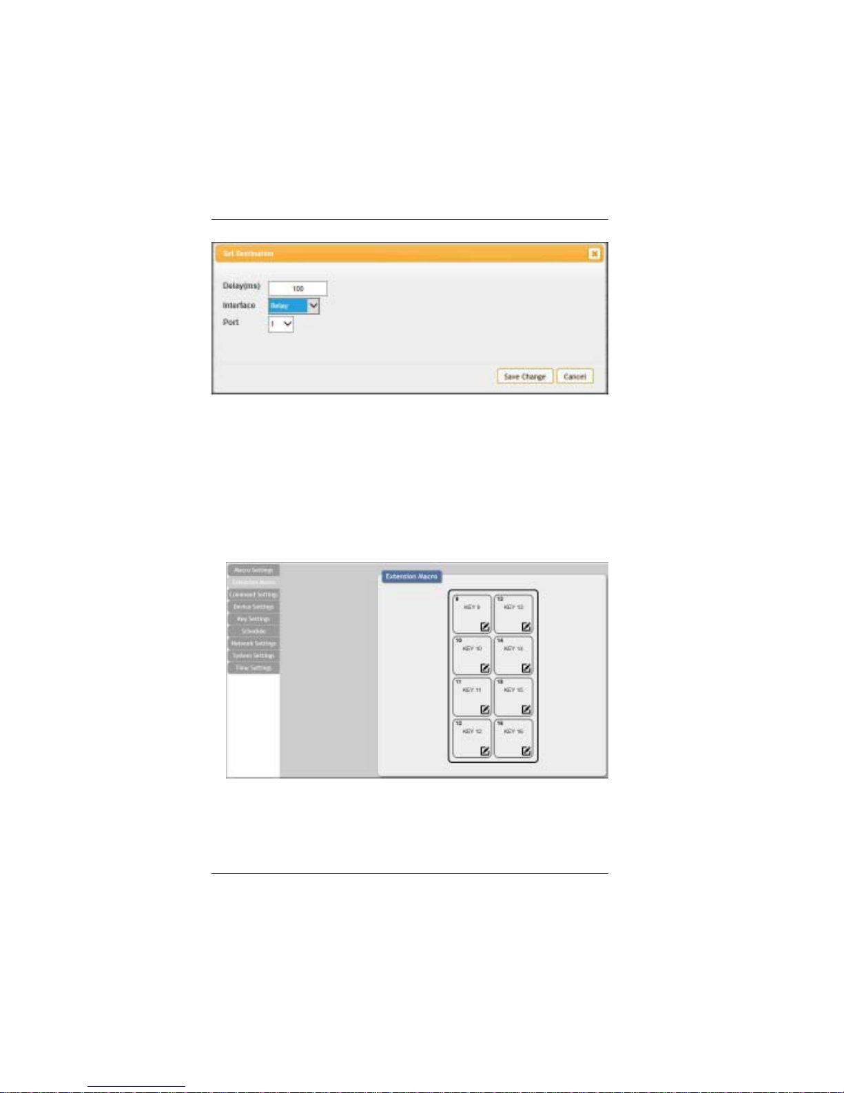
Command set to control the Relay devices require to set the
Port number. Click on Save Change to confirm the setting.
Page 13
LB-KP8E User Manual
Link Bridge
TM
8-Button Wall Plate Ethernet Controller
Broadata Technical Support, (800) 214-0222
14
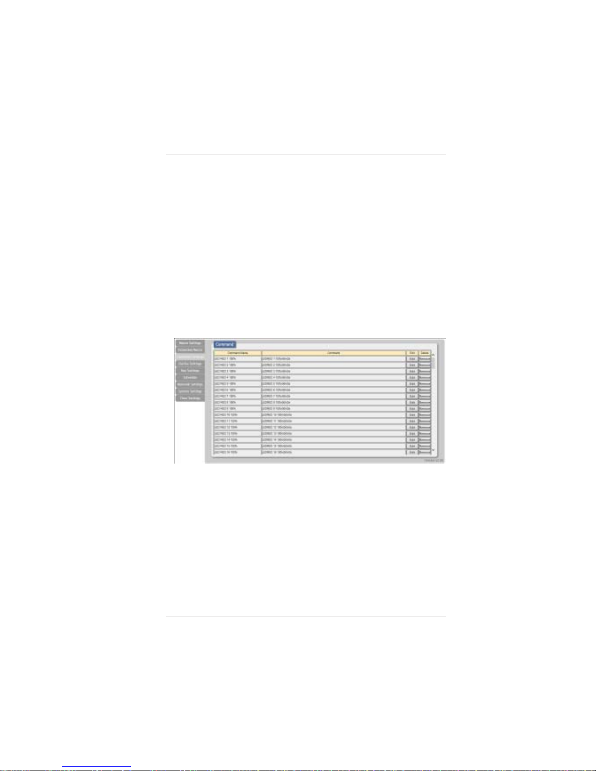
2.5.2 Extension Macro
Click on Extension Macro to execute/edit up to 8 more Macro
actions,
Page 14
LB-KP8E User Manual
Link Bridge
TM
8-Button Wall Plate Ethernet Controller
Broadata Technical Support, [email protected]
15
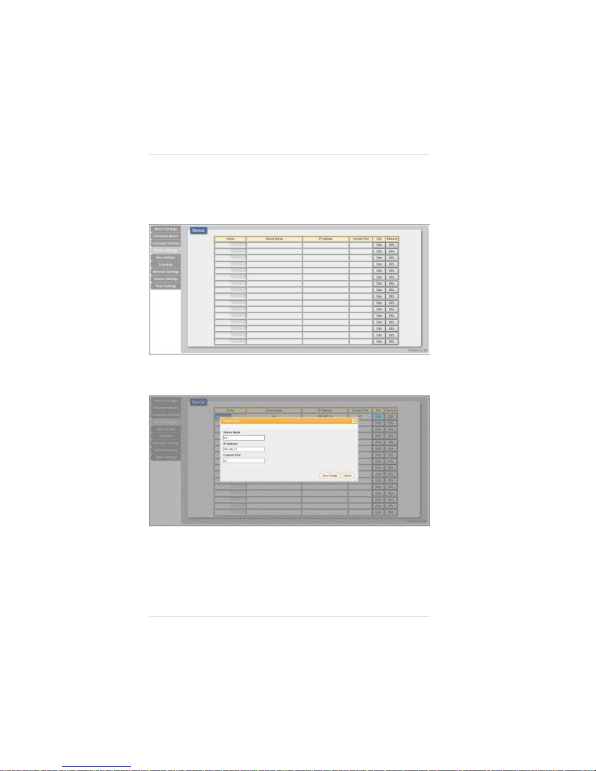
2.5.3 Command Settings
Click on Command Settings to insert new commands or delete
commands.
A maximum of 128 commands are supported (each command
is less than 128 characters including spaces).
Alternatively , up to 32 commands (each command greater than
128 characters and less than 512 characters including spaces)
plus 96 commands (each command less than 128 characters
including spaces) are supported.
Click on Save Change to save the command.
Page 15
LB-KP8E User Manual
Link Bridge
TM
8-Button Wall Plate Ethernet Controller
Broadata Technical Support, (800) 214-0222
16
2.5.4 Device Settings
Click on Device Settings to setup the IP Address of a device.
Click on Edit to add a new device to be controlled. Enter the
Device Name, IP Address and Connect Port.
Page 16

LB-KP8E User Manual
Link Bridge
TM
8-Button Wall Plate Ethernet Controller
Broadata Technical Support, [email protected]
17
2.5.5 Key Settings
Click on Key Settings to configure the repeat or toggle setting
of a key . If Repeat is set to On, pressing and holding the key
causes the programmed macro to be repeated. If T oggle is set
to On, pressing the key the first time executes the macro for
that key. Pressing the key a second time executes the
extension macro for the corresponding key. Note: Key 17 is
the corresponding toggle key for Key 1.
Page 17
LB-KP8E User Manual
Link Bridge
TM
8-Button Wall Plate Ethernet Controller
Broadata Technical Support, (800) 214-0222
18
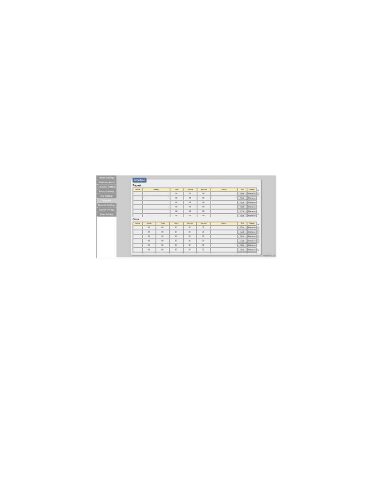
2.5.6 Schedule
Click on Schedule to set the executing time schedule of the
Macro(s).
Note: The scheduling system supports up to 48hrs of memory
under power blackout after that the system will reset the time
automatically back to 2015/01/01 00:00:00.
Page 18
LB-KP8E User Manual
Link Bridge
TM
8-Button Wall Plate Ethernet Controller
Broadata Technical Support, [email protected]
19
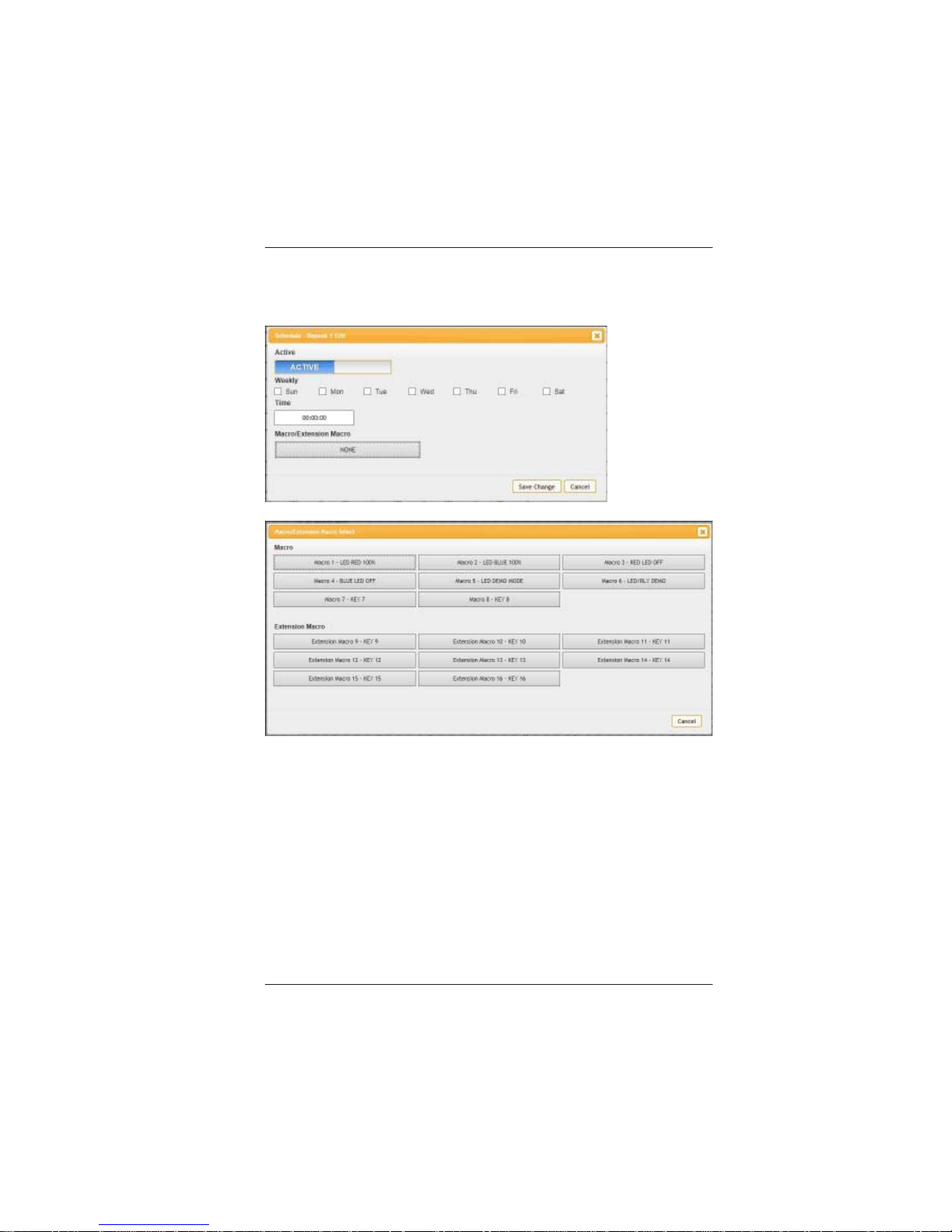
Click on Edit from Repeat column to set the macro command(s)
to be activated repeatedly on a set time.
Page 19
LB-KP8E User Manual
Link Bridge
TM
8-Button Wall Plate Ethernet Controller
Broadata Technical Support, (800) 214-0222
20
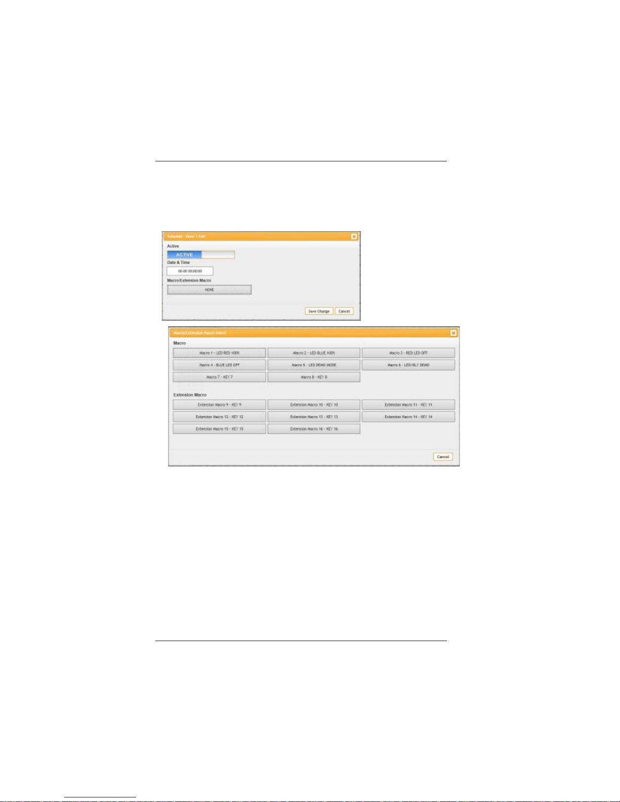
Click on Edit from Once column to set the macro command(s)
to be activated on a set time only .
Page 20
LB-KP8E User Manual
Link Bridge
TM
8-Button Wall Plate Ethernet Controller
Broadata Technical Support, [email protected]
21
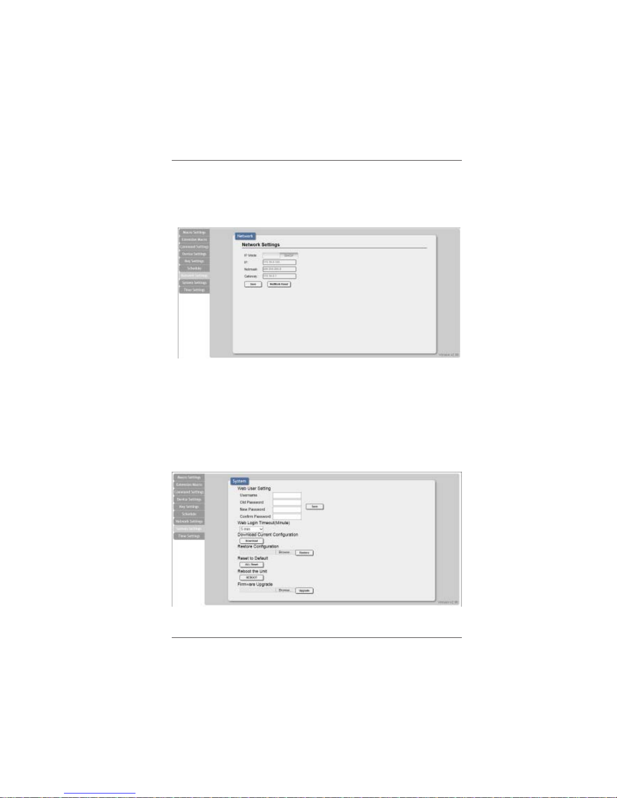
2.5.7 Network Settings
Click on Network Settings to reset the IP , Netmask or Gateway
address.
2.5.8 System Settings
Click on System Settings to reset the WebGUI login password
and timeout setting and save or download the Macro settings.
Reset to Default allows IP and login ID & password to be reset
back to factory default.
Page 21
LB-KP8E User Manual
Link Bridge
TM
8-Button Wall Plate Ethernet Controller
Broadata Technical Support, (800) 214-0222
22
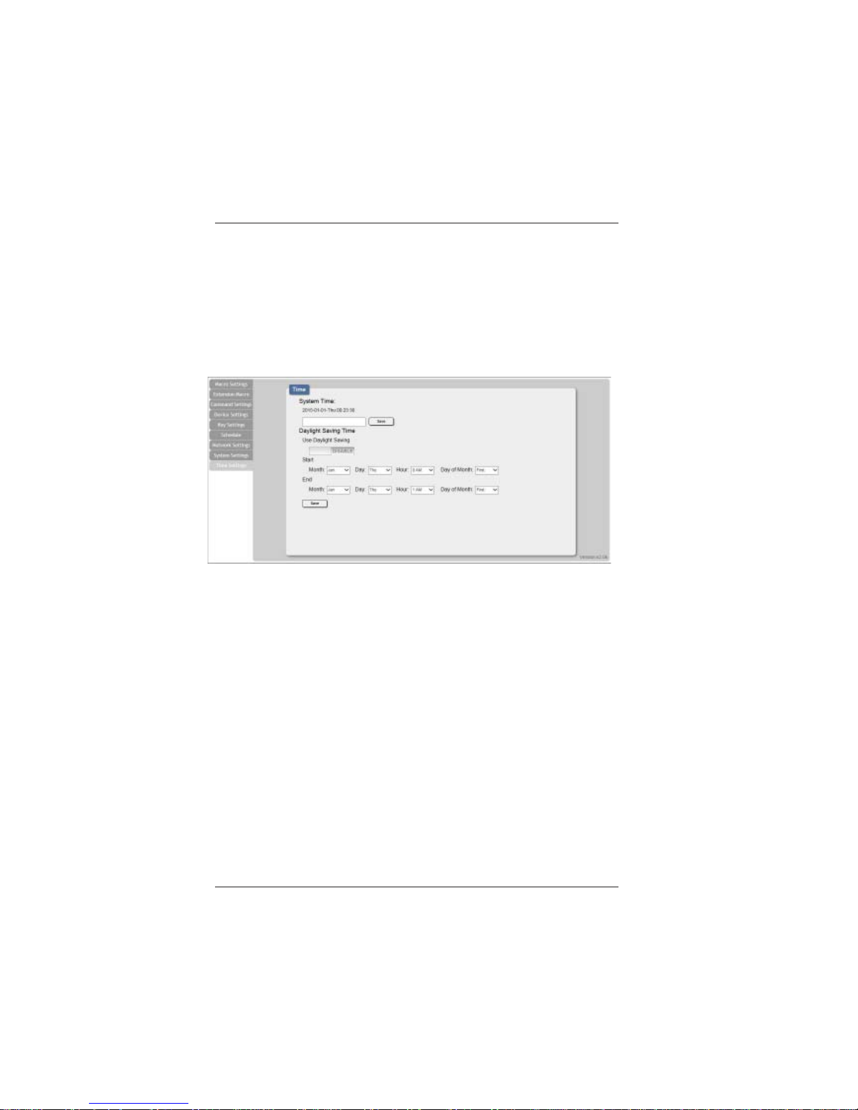
2.5.9 Time Settings
Click on ‘Time Settings’ to set the system time and to enable/
disable Daylight Saving Time(DST) function. Simply click on
the white column and a calendar will appear for your selection
with current timing setting. Another simple few clicks to enable/
disable DST with its start and end.
Page 22

LB-KP8E User Manual
Link Bridge
TM
8-Button Wall Plate Ethernet Controller
Broadata Technical Support, [email protected]
23
3.0 MAINTENANCE AND TROUBLESHOOTING
3.1 Maintenance
There is no operator maintenance other then keeping the units
clean. However, observe the following light indicators to make
sure that the unit is working properly:
3.2 Troubleshooting
If the LB-KP8E units do not operate properly after installation,
check for possible cable breaks, loose connections, and
incorrect cable connections. If problems persist that may be
fiber related, contact BCI at 1-800-214-0222 for further
assistance.
For electrical problems, perform the following troubleshooting
procedures:
1. If the POWER indicator is OFF , check for the following:
a. The line cord is plugged into the unit and your outlet
has power.
2. If the POWER indicator is ON, but the Link indicator is
OFF, check for the following:
a. Make sure the appropriate cables are being used.
b. Cable and cable connectors are not broken.
c. For each unit, the transmit (TX) cable is connected to
the other unit’s receiver (RX).
3. If the POWER indicator and Link indicator are ON, but
the channels are not operating, then:
a. Check to see that the attached user equipment is turned
on.
b. Both ends of the link are connected to the
corresponding equipment and to the same
corresponding channel port.
Page 23

LB-KP8E User Manual
Link Bridge
TM
8-Button Wall Plate Ethernet Controller
Broadata Technical Support, (800) 214-0222
24
c. Cable connections at both channels are securely
fastened to each connector. T urn the power of f, then
back on to reset the link.
Page 24

LB-KP8E User Manual
Link Bridge
TM
8-Button Wall Plate Ethernet Controller
Broadata Technical Support, [email protected]
25
4.0 SPECIFICATIONS
I/O CONNECTORS
Keypad 8 buttons
I/O Ethernet (1), RJ-45
Relay (1), Terminal Block
PHYSICAL
Dimensions (W x H x D) 3.62” x 4.07” x 1.50”
Operating T emperature 0oC to +40oC
Storage T emperature -20oC to +60oC
Power Supply 5V/2.6A
Page 25

LB-KP8E User Manual
Link Bridge
TM
8-Button Wall Plate Ethernet Controller
Broadata Technical Support, (800) 214-0222
26
5.0 SERVICE PROCEDURE
5.1 Replacement Policy
Standard products found defective on arrival (DOA) will be
replaced, based on availability , within 24 to 48 hours anywhere
in the U.S. Please call Customer Service at 800-214-0222 for
information.
5.2 Return/Repair Service
The LB-KP8E System contains no user serviceable
components. If you have a problem with your unit, please contact
the Customer Service Department. To facilitate our return/rep air
processing please contact Broadata Communications, Inc. to
obtain a Return Material Authorization (RMA). Please include
the following information:
• Product model number
• Serial Number
• Complete description of problem
• Hardware installation description
Broadata Communications, Inc.
2545 West 237th Street, Suite K
T orrance, CA 90505
1-800-214-0222
(310) 530-1416
(310) 530-5958 (Facsimile)
e-mail: [email protected]
Website: www .broadatacom.com
Page 26

LB-KP8E User Manual
Link Bridge
TM
8-Button Wall Plate Ethernet Controller
Broadata Technical Support, [email protected]
27
6.0 LIMITED W ARRANTY
Broadata Communications, Inc. (BCI) warrants, for a period of one year
from date of shipment, each product sold shall be free from defects in
material and workmanship. BCI will correct, either by repair, or at BCI’ s
election, by replacement, any said products that in our sole discretion
prove to be defective and are returned to the manufacturing location
within 30 days after such defect is ascertained. All warranties are limited
to defects arising under normal use and do not include malfunctions or
failure resulting from misuse, abuse, neglect, alterations, electrical power
problems, usage not in accordance with product instructions, improper
installation, or damage determined by BCI to have been caused by the
Buyer or repair made by a third party. Limited warranties granted on
products are to the initial customer end-user and are not transferable.
OUR LIABILITY UNDER THIS W ARRANTY SHALL IN ANY CASE BE
LIMITED TO THE INVOICE VALUE OF THE PRODUCT SOLD AND BCI
SHALL NOT BE LIABLE TO ANYONE FOR CONSEQUENTIAL OR
INCIDENT AL DAMAGES ARISING FROM THE USE OF ITS PRODUCTS
OR THE SALE THEREOF. We make NO WARRANTY AS TO THE
MERCHANT ABILITY OF ANY GOODS, OR THA T THEY ARE FIT FOR
ANY P ARTICULAR PURPOSE OR END APPLICA TION NOR DO WE
MAKE ANY WARRANTY, EXPRESSED OR IMPLIED OTHER THAN
AS ST A TED ABOVE.
Page 27

LB-KP8E User Manual
Link Bridge
TM
8-Button Wall Plate Ethernet Controller
Broadata Technical Support, (800) 214-0222
28
Page 28

Broadata Communications, Inc.
2545 West 237th Street, Suite K
Torrance, CA 90505
1-800-214-0222
(310) 530-1416
(310) 530-5958 (Facsimile)
e-mail: [email protected]
Website: www.broadatacom.com
60000-LB-KP8E
 Loading...