

Page 1
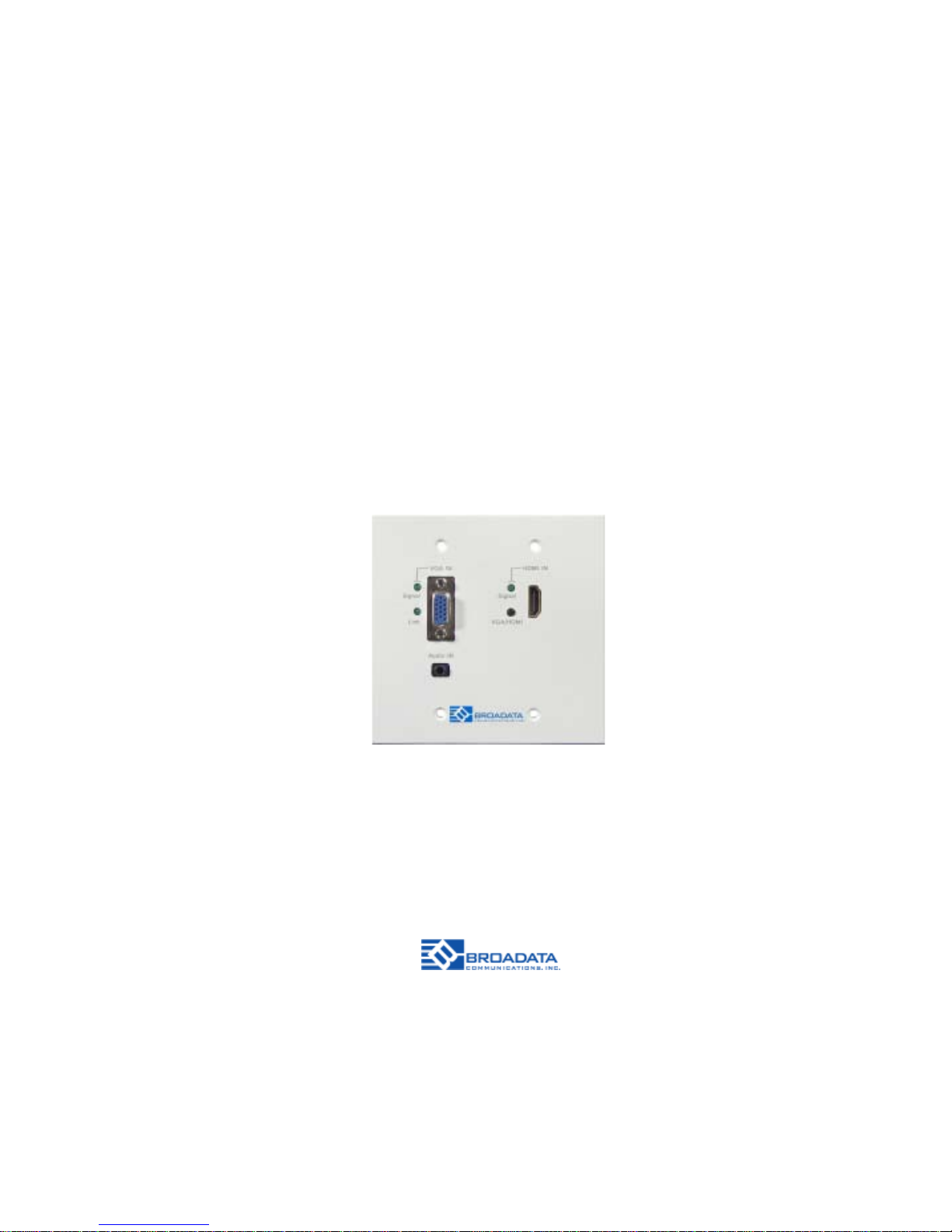
LBC-H/V-T-WP
LINK BRIDGETM HDMI/VGA
WALL PLATE TRANSMITTER SYSTEM
BCI reserves the right to make changes to the products described herein without prior
notice or consent. No liability is assumed as a result of their use or application. All
rights reserved.
©2013 Broadata Communications, Inc.
Page 2

LBC-H/V-T -WP User’s Manual
Link Bridge
TM
HDMI/VGA W all Plate Transmitter System
Broadata Technical Support, [email protected]
3
SAFETY INSTRUCTIONS AND
COMPLIANCE DECLARA TIONS
PLEASE OBSERVE THE FOLLOWING SAFETY
PRECAUTIONS
SURGE PROTECTION DEVICE RECOMMENDED
This product contains sensitive electrical components that may be
damaged by electrical spikes, surges, electric shock, lightning strikes,
etc. Use of surge protection systems is highly recommended in order
to protect and extend the life of your equipment.
Page 3

LBC-H/V-T -WP User’s Manual
Link Bridge
TM
HDMI/VGA Wall Plate Transmitter System
Broadata Technical Support, (800) 214-0222
4
TABLE OF CONTENTS
1.0 PRODUCT DESCRIPTION ..............................................5
2.0 OPERATION CONTROLS AND FUNCTIONS .................6
2.1 FRONT PANEL .................................................................6
2.2 REAR P ANEL ...................................................................7
3.0 SET UP.............................................................................8
3.1 MOUNTING.......................................................................8
3.2 CABLING AND CONNECTORS.......................................8
3.3 VGA/YPBPR VIDEO INTERFACE ...................................9
3.4 HDMI VIDEO INTERFACE..............................................10
3.5 AUDIO INTERF ACE........................................................1 1
3.6 SERIAL DA TA INTERF ACE............................................1 2
3.7 CA T-5E/6 TRANSMISSION CONNECTION ...................13
4.0 DC POWER CONNECTION...........................................14
4.1 IN-WALL POWER/CAT-5E/6 WIRING INSTRUCTION ..15
5.0 AUTOMATED DISPLAY CONTROL...............................17
5.0 MAINTENANCE AND TROUBLESHOOTING ...............24
5.1 MAINTENANCE ..............................................................2 4
5.2 TROUBLESHOOTING ...................................................24
6.0 SPECIFICA TIONS...........................................................26
7.0 SERVICE PROCEDURE ................................................27
7.1 REPLACEMENT POLICY ..............................................27
7.2 RETURN AND REPAIR SERVICE .................................27
8.0 LIMITED WARRANTY ....................................................28
Page 4

LBC-H/V-T -WP User’s Manual
Link Bridge
TM
HDMI/VGA W all Plate Transmitter System
Broadata Technical Support, [email protected]
5
1.0 PRODUCT DESCRIPTION
The LBC-H/V-T-WP transmitter is a high performance, low cost,
miniature, Link BridgeTM HDBaseT VGA/HDMI Transmission System
that embeds the source audio into the VGA video signal. It carries one
(1) unidirectional HDMI video or one VGA/YPbPr signal with one (1) unidirectional embedded stereo audio, and one (1) RS-232 data channel.
This unique CAT 5e/6 transmission system lets your digital flat panel
display extend up to 70m (230 ft) at 4K2K and WUXGA (1920x1200 @
60Hz) or 720p/1080i/1080p HDTV video resolution.
LBC-H/V-T -WP is a 2 gang multi-input wall plate transmitter . When either
the VGA or HDMI with active signal is connected, the signal will be sent
to the compatible HDBaseT receiver automatically. The ‘VGA/HDMI’
button on the wall plate is available for manual signal selection if both
VGA and HDMI with active signal inputs are connected at the same time.
The Wall plate is also capable of being controlled via RS-232 commands
sent by a local RS-232 connection or via a remote HDBaseT receiver . In
addition, the LBC-H/V-T -WP supports PoH (Power over HDBaseT) where
it can be powered by a remote Matrix, a compatible receiver or local DC
adapter.
LBC-H/V-T -WP also comes up with an automated display control which
can automatically turn on/off display monitor upon the presence/absence
of input video signal. Section 5.0 details this feature.
In addition, the LBC-H/V-T-WP transmitter is compatible with our LBH
and LBC Series receivers. This makes both CA T 5e/6 transmission and
HDMI/DVI/VGA/YPbPrI conversion in one single system setup. The units
are easily monitored by power and link LED indicators. Figures 2-1, and
2-2 illustrate the front and rear panels of the LBC-H/V-T-WP unit.
Page 5
LBC-H/V-T -WP User’s Manual
Link Bridge
TM
HDMI/VGA Wall Plate Transmitter System
Broadata Technical Support, (800) 214-0222
6
2.0 OPERA TION CONTROLS AND FUNCTIONS
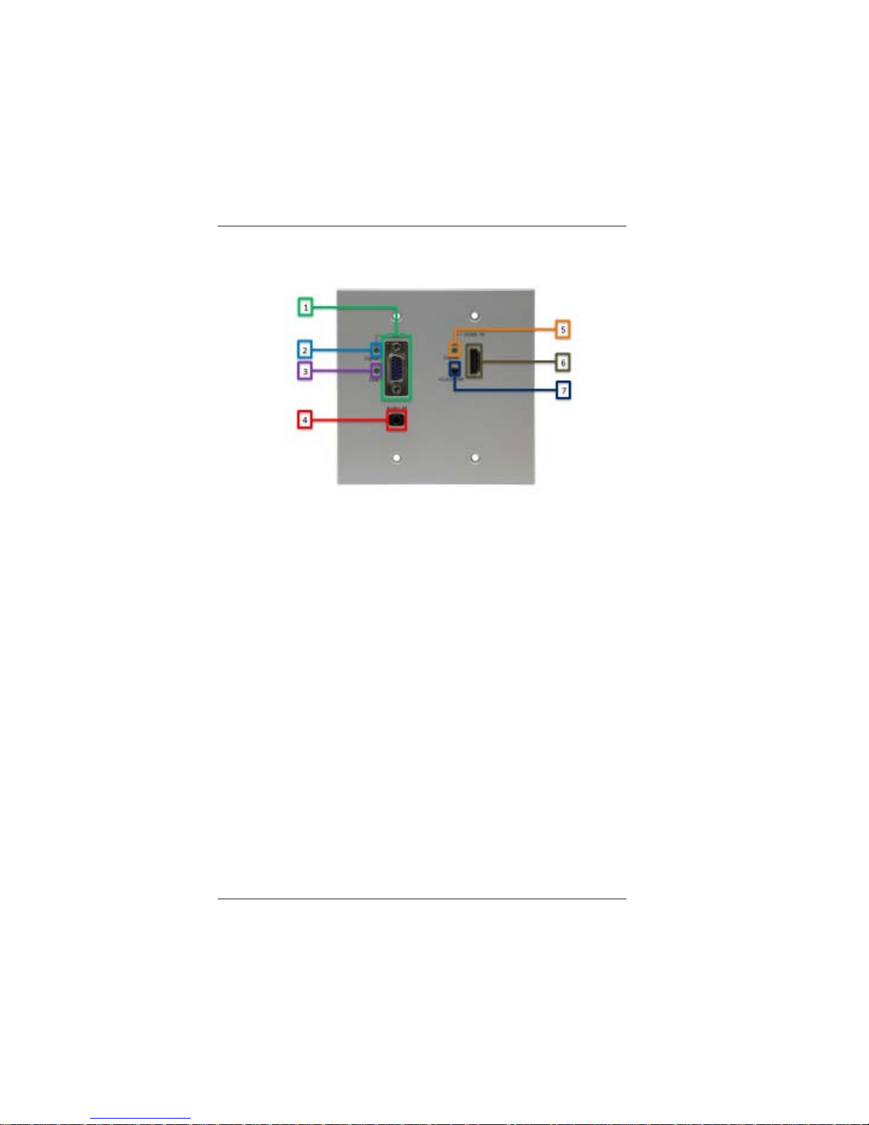
1. VGA Input: Connect to VGA source.
2. LED for VGA: LED blinking means there is VGA signal input;
LED always on means current output is VGA.
3. LINK LED for HDBT connection: LED blinking means
CAT-5e/6 cable connection available; LED always on means
there is videosignal input and output.
4. Analog Audio Input: Connect to audio source. This audio is
embedded with VGA.
5. LED for HDMI: LED blinking means there is HDMI signal input;
LED always on means current output is HDMI.
6. HDMI Input: Connect to HDMI source.
7. Signal Switch Button: Manual selection of the input signal.
Figure 2-1
LBC-H/V-T-WP Front Panel
Page 6
LBC-H/V-T -WP User’s Manual
Link Bridge
TM
HDMI/VGA W all Plate Transmitter System
Broadata Technical Support, [email protected]
7
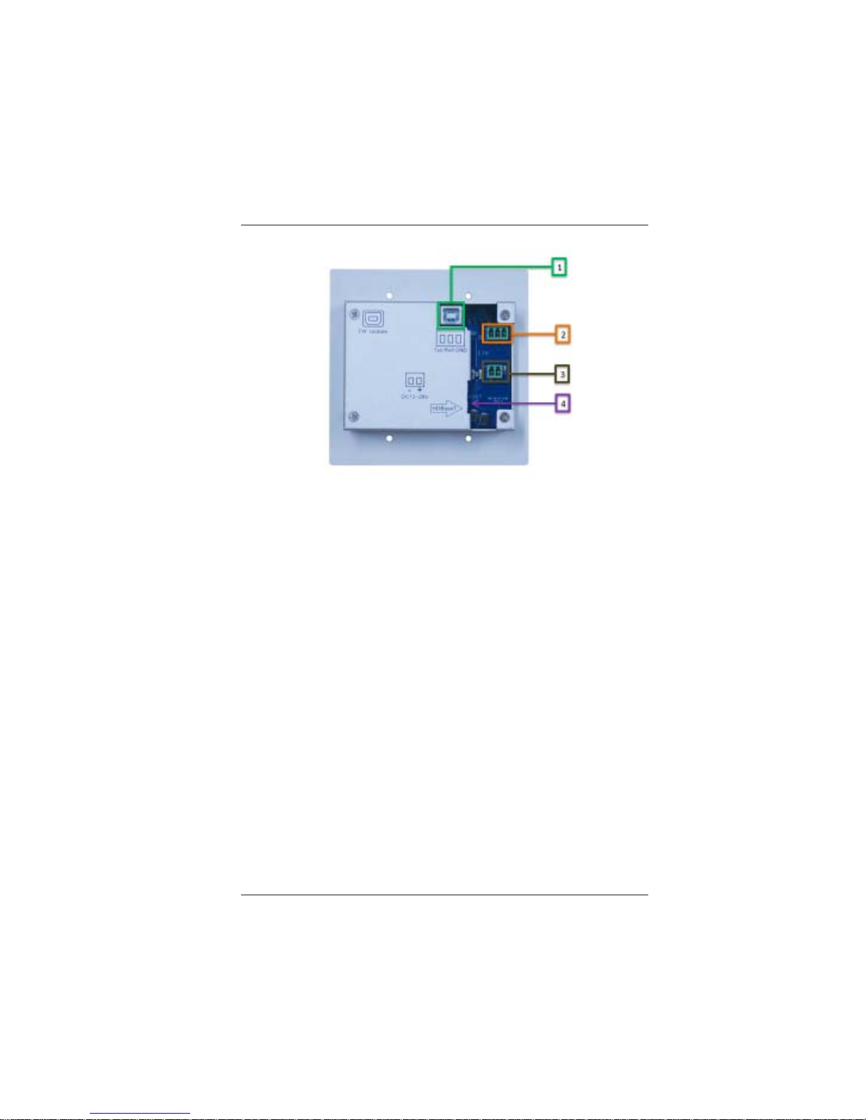
1. Firmware Update USB port
2. RS-232 control port (refer to RS232 protocol on pg 17)
3. Power input
4. HDBaseT CA TX connection
Figure 2-2
LBC-H/V-T-WP Rear Panel
Page 7
LBC-H/V-T -WP User’s Manual
Link Bridge
TM
HDMI/VGA Wall Plate Transmitter System
Broadata Technical Support, (800) 214-0222
8
3.0 SETUP
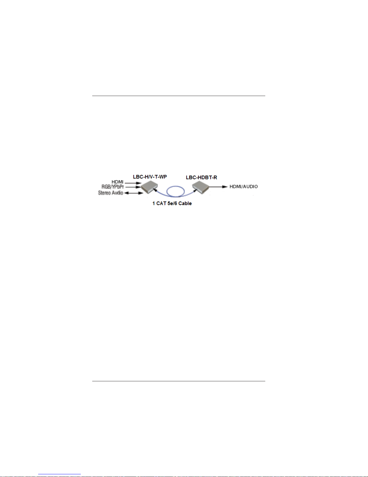
The BCI LBC HDBaseT Extender Series units are used in pairs. One
LBC-H/V-T -WP transmitter unit is located at the near-end (source) and
connected through a single category cable, to one of the LBC or LBH
receivers like the LBC-HDBT-R receiver shown below and located at
the far-end (sink) of the link. Figure 3-1 depicts a typical installation for
the LBC-H/V-T -WP and LBC-HDBT -R.
3.1 Mounting
Before installing the units into your housing, make sure there is
enough space to pull and connect both the electrical and category
cables without stressing them beyond the manufacturer’s
limitations (also known as the minimum bend radius).
3.2 Cabling and Connectors
In order to setup the LBC-H/V-T-WP properly, make sure to
observe the following instructions when installing the proper
cables. The LBC-H/V-T-WP requires two parts to the cabling
setup, the video signal and the transmission connections.
Figure 3-1
LBC-H/V-T-WP with LBC-HDBT-R Transmission Pair
Page 8
LBC-H/V-T -WP User’s Manual
Link Bridge
TM
HDMI/VGA W all Plate Transmitter System
Broadata Technical Support, [email protected]
9
3.3 VGA/YPbPr Video Interface
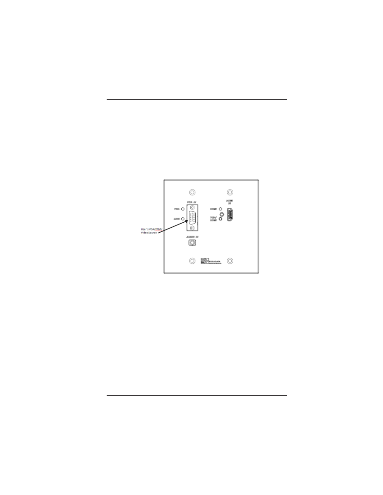
The RGB/YPbPr video connection is the VGA (HD-15) plug
connectors for video input port. Use the following instructions
to properly connect your component video as illustrated in
Figure 3-2. Connect the LBC-H/V-T-WP (Transmitter) unit’s
RGB/YPbPr video input port to the user’s RGB/YPbPr video
source with the appropriate VGA (HD-15) cables.
Figure 3-2
Connect User’s VGA or YPbPr Video Source
Page 9
LBC-H/V-T -WP User’s Manual
Link Bridge
TM
HDMI/VGA Wall Plate Transmitter System
Broadata Technical Support, (800) 214-0222
10
3.4 HDMI Video Interface
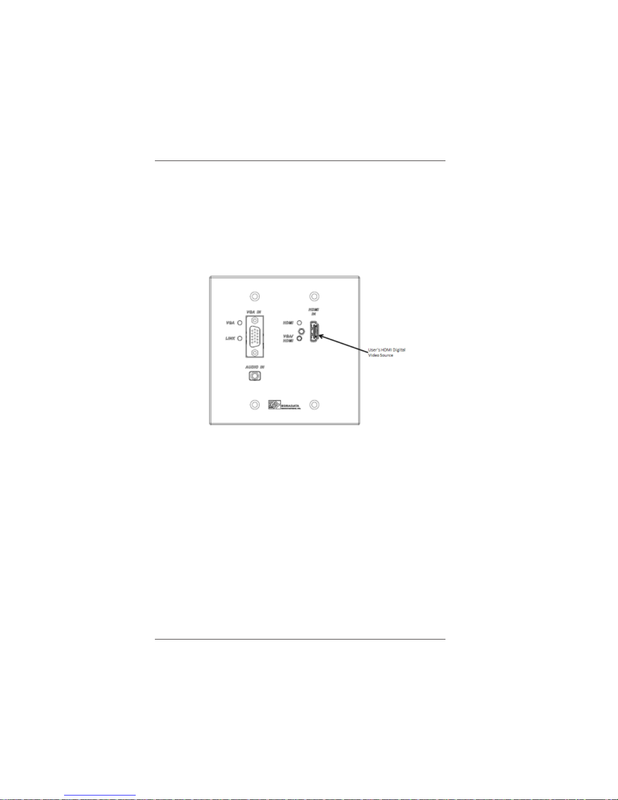
The HDMI video connection is the HDMI plug connectors for the
video input port. Use the following instructions to properly connect
your video as illustrated in Figure 3-3. Connect the
LBC-H/V-T -WP (T ransmitter) unit’s to HDMI video input port to
the user’s HDMI video source with the appropriate HDMI cables.
Figure 3-3
Connect User’s HDMI Video Source
Page 10
LBC-H/V-T -WP User’s Manual
Link Bridge
TM
HDMI/VGA W all Plate Transmitter System
Broadata Technical Support, [email protected]
11
3.5 Audio Interface
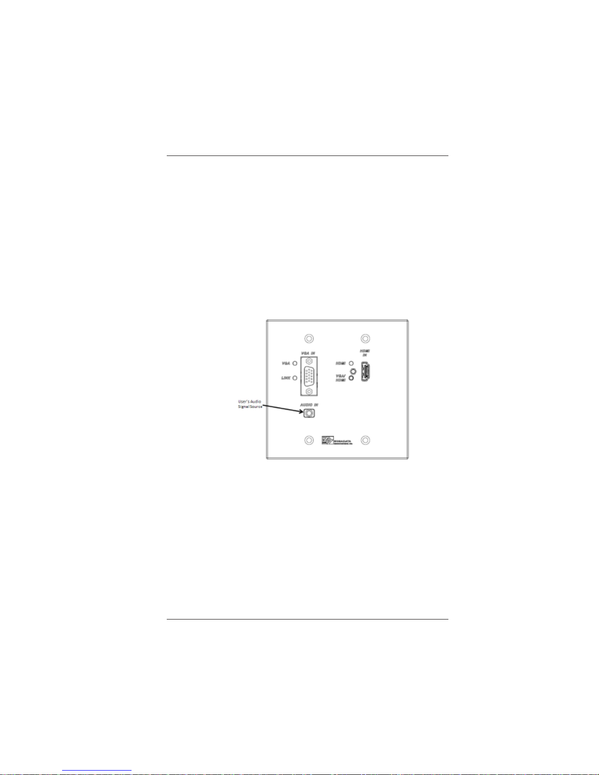
The audio interface supports one stereo channel high fidelity
analog, line-level audio signal connected to the LBC-H/V-T -WP
unit. This audio is embedded with VGA signal. The following
steps illustrate the installation procedures for audio devices.
T o send audio signals, label and connect one stereo audio-jack
cable to the “AUDIO” connector of the line level audio source.
On the LBC-H/V-T -WP unit, connect the other end of the cables
to the front panel stereo jack connector labeled “AUDIO IN”
(see Figure 3.4).
Figure 3-4
User’s Analog/Digital Audio Source
Page 11
LBC-H/V-T -WP User’s Manual
Link Bridge
TM
HDMI/VGA Wall Plate Transmitter System
Broadata Technical Support, (800) 214-0222
12
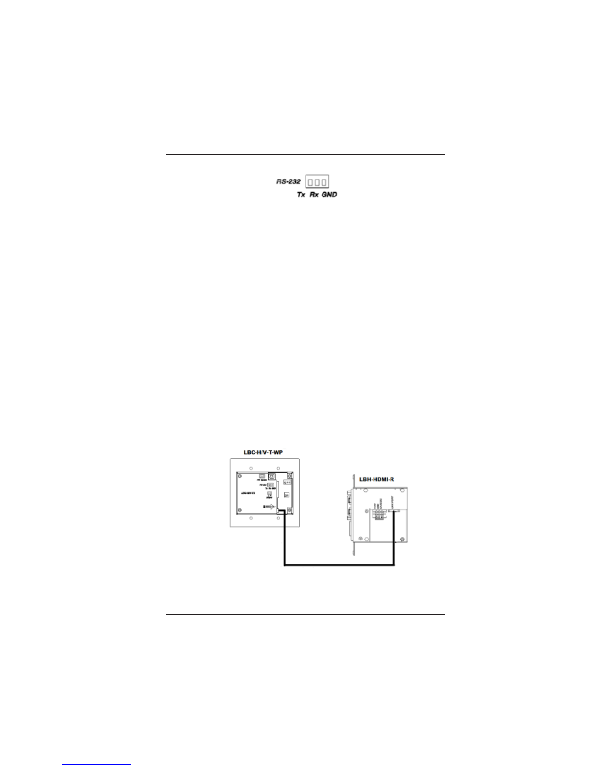
3.6 Serial Data Interface
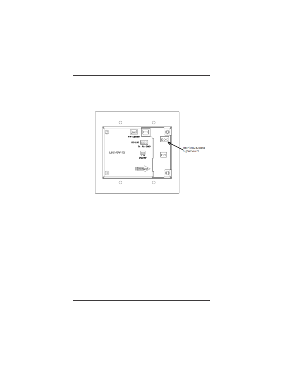
To transmit RS-232 data, connect data source to the terminal
block shown in Figure 3-5.
RS-232 Data
The LBC-H/V-T-WP transmits one channel of RS-232 data.
Follow the procedures for installing data terminal devices.
1. Label and connect one serial data cable to the user’s RS-232
device.
2. Connect the other end of this cable to the rear panel data
terminal block connector on the LBC-H/V-T-WP (see
Figure 3-5) per the pin out diagram in Figure 3-6.
Figure 3-5
User’s RS-232 Data Source
Page 12
LBC-H/V-T -WP User’s Manual
Link Bridge
TM
HDMI/VGA W all Plate Transmitter System
Broadata Technical Support, [email protected]
13
Note: Refer to Table 1 on page 17 for the RS-232 command
protocol.
3.7 CA T -5e/6 Transmission Connection
Select an appropriate terminated shielded CA T 5e/6 cable. Each
unit’s RJ45 ports in the system are specified for use with RJ45
connectors. Follow the ensuing instructions on installing and
connecting the HDBaseT links:
1. Ensure the power is off before proceeding with the CA T5e/6
cable installation.
2. Connect the cable from one unit to the other connecting the
near end LBC-H/V-T -WP unit’s RJ45 port and to the far end
of the LBH-HDMI-AD-R (use any compatible LBC or LBH
series receiver) unit’s RJ45 RX port as illustrated in
Figure 2-7.
Figure 3-6
RS-232 Terminal Block Pin OUT
Figure 3-7
CAT-5e/6 Connection
Page 13

LBC-H/V-T -WP User’s Manual
Link Bridge
TM
HDMI/VGA Wall Plate Transmitter System
Broadata Technical Support, (800) 214-0222
14
4.0 DC POWER CONNECTION
Congratulations! You are now ready to power up the LBC-H/V-T-WP
and set up your network connection. In order to make sure that you
have a proper installation, please observe the following:
1. Your AC jack has power.
2. The 24VDC power supply is working.
3. Your electrical system has proper grounding (this ensures that
your power supply does not suffer from voltage variations).
4. Power Surge Protection. This is optional, but highly
recommended. A UPS system provides voltage regularity as
well as prevents spikes from occurring, thus protecting your
LBC-H/V-T -WP from sensitive voltage conditions.
The LBC-H/V-T -WP derives power from an external 24VDC power supply
or via PoH (Power over HDBaseT). This power supply is a wall mounted
AC/DC adapter, 100-240 VAC, 50-60 Hz, at 1.0A. This power supply
comes standard for the LBC-H/V-T -WP unless otherwise specified. To
provide power to the LBC-H/V-T-WP, simply connect the power cord,
already provided with the units, and connect it to the wall jack. (Y ou will
find one power cord per unit). Once the power cord has been connected
to the wall jack, connect 24VDC to the unit and the unit should power up
immediately. If you have any problems or concerns, regarding the
installation, make sure that you have taken the proper steps to ensure
a proper power connection. Otherwise, feel free to contact us for any
questions you may have.
Page 14
LBC-H/V-T -WP User’s Manual
Link Bridge
TM
HDMI/VGA W all Plate Transmitter System
Broadata Technical Support, [email protected]
15
4.1 In-Wall Power/CA T -5e/6 Wiring Instruction
The in-wall power/CA T-5e/6 inst allation for the LBC-H/V-T -WP
wall plate must confirm national and local electrical codes, e.g.,
UL junction boxes shall be used and DC power source shall not
exceed product rated range (+24VDC @ 1A). Follow the
following steps for power/CAT5e/6 installation:
1. Feed both CAT -5e/6 and power cables through the opening
of the wall box, and secure the cables with cable clamps
to provide strain relief.
2. Terminated CAT-5e/6 with RJ45 connector to be directly
plugged into the RJ45 connector port of the
LBC-H/V-T -WP unit.
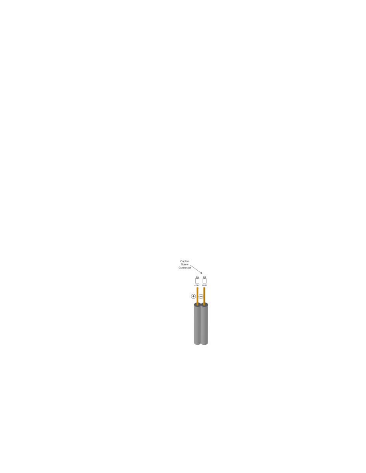
3. Before connecting power wire to the LBC-H/V-T -WP unit,
make sure power supply is off. Prepare the Positive (+24V)
and chassis ground (CHASSIS to earth ground) tip of the
power wire as shown in Figure 3-8 to be directly plugged
into the captive screw +24VDC connector of the
LBC-H/V-T -WP unit.
Make sure the polarity of the connection is correct. Insulate
any exposed wire shields to prevent short circuits.
Figure 4-1
Power Connection
Page 15

LBC-H/V-T -WP User’s Manual
Link Bridge
TM
HDMI/VGA Wall Plate Transmitter System
Broadata Technical Support, (800) 214-0222
16
Note 1: During installation, the installer may need to connect
the power supply output to an appropriate Listed NEC type
cable before it is routed behind a wall. Simply routing the power
supply output cable behind a wall will most likely not comply
with applicable installation requirements. Unit should only be
powered by a power source that is Listed (NEC) Class 2 or a
Listed ITE Power Supply marked/rated as LPS or Limited Power
Source.
Note 2: The installation shall be in accordance with the applicable
provisions of the National Electrical Code ANSI/NFP A 70, Article
725 and the Canadian Electrical Code, Part 1, Section 16.
Note 3: The power supply shall not be permanently fixed to the
building structure or similar structures.
Note 4: The power supply shall not be located within
environmental air handling spaces or within the wall cavity .
Note 5: The power supply is to be located within the same
vicinity as the A/V processing equipment in an ordinary location,
Pollution Degree 2, secured to the equipment rack within the
dedicated closet, podium or desk.
Page 16

LBC-H/V-T -WP User’s Manual
Link Bridge
TM
HDMI/VGA W all Plate Transmitter System
Broadata Technical Support, [email protected]
17
5.0 AUTOMATED DISPLAY CONTROL
The LBC-H/V-T-WP may be used to control the LCD or Projector
connected to the HDBaseT receiver. When the LBC-H/V -T -WP is “woken
up” by connecting a video source, it will send the preprogrammed “Power
ON” command, followed by the “2nd command” and “3rd command.”
When the LBC-H/V-T -WP times out due to lack of video or activity , it will
send the preprogrammed “Power Off” command.
One will use LBC-H/V-T -WP Configuration Utility in a PC to pre-configure
the above automated display control commands.
Automated Display Control Functional Details
1. Upon detection of HDMI or VGA signal activity , the unit is capable
of sending the ‘Power On Command,’ ‘2nd Command,’ and ‘3
rd
Command’ to the connected display monitor via HDBaseT receiver
unit’s RS-232 port. The user will configure the delay between the
commands via the Configuration Utility .
2. Upon disconnection of the HDMI or VGA signal by the user and
reaching the time out configured by the user due to lack of video,
the unit will send the preprogrammed “Power Off” command to
the connected display.
3. The unit will detect RS232 response from the display for
acknowledgement of receipt of the Power On command code.
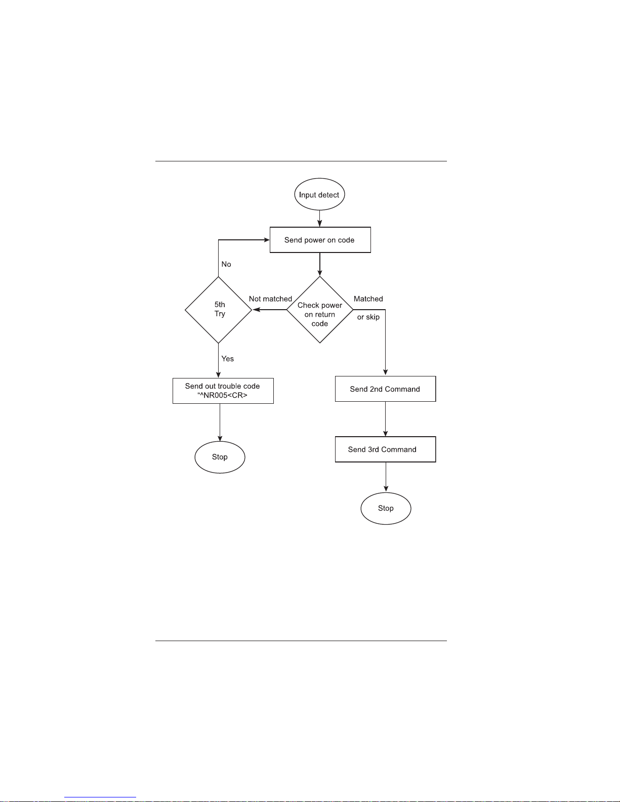
4. The unit will automatically send out a trouble code (^NR005<CR>),
if it does not receive an RS232 response on Power On command
after 5 repeated attempts (unless user selects ‘skip checking
power on return code’),
5. The unit will be capable of display control directly from work
station using the LBC-H/V-T -WP configuration utility.
Figure 5-1 illustrates the flow chart of this automated display control.
Page 17
LBC-H/V-T -WP User’s Manual
Link Bridge
TM
HDMI/VGA Wall Plate Transmitter System
Broadata Technical Support, (800) 214-0222
18
Figure 5-1
LBC-H/V-T-WP Automation Flow Chart
Page 18
LBC-H/V-T -WP User’s Manual
Link Bridge
TM
HDMI/VGA W all Plate Transmitter System
Broadata Technical Support, [email protected]
19
LBC-H/V-T-WP Configuration Utility, Operational Det ails
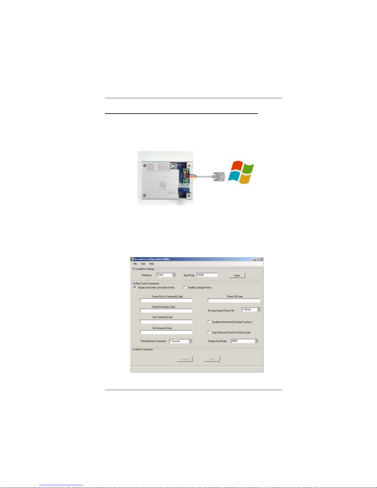
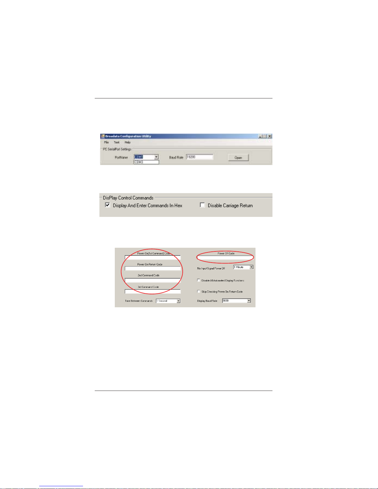
1. Connect your PC to the LBC-H/V -T-WP’ s RS-232 port using a serial
cable.
2. Click on the utility to open the Broadata configuration dialog box:
(*NOTE: images below are simulated to illustrate functionality,
actual configuration utility will need to have alternate layout.)
Page 19
LBC-H/V-T -WP User’s Manual
Link Bridge
TM
HDMI/VGA Wall Plate Transmitter System
Broadata Technical Support, (800) 214-0222
20
3. Using the Communication pull down menu ensure the com port is
available for connection to the LBC-H/V-T-WP, and click ‘Open’
button.
4. Select Display Control Commands option.
5. Enter the display command codes for ‘Power On,’ ‘Power Off,’ ‘2
nd
Command,’ ‘3rd Command’ and ‘Power On return code.
Page 20
LBC-H/V-T -WP User’s Manual
Link Bridge
TM
HDMI/VGA W all Plate Transmitter System
Broadata Technical Support, [email protected]
21
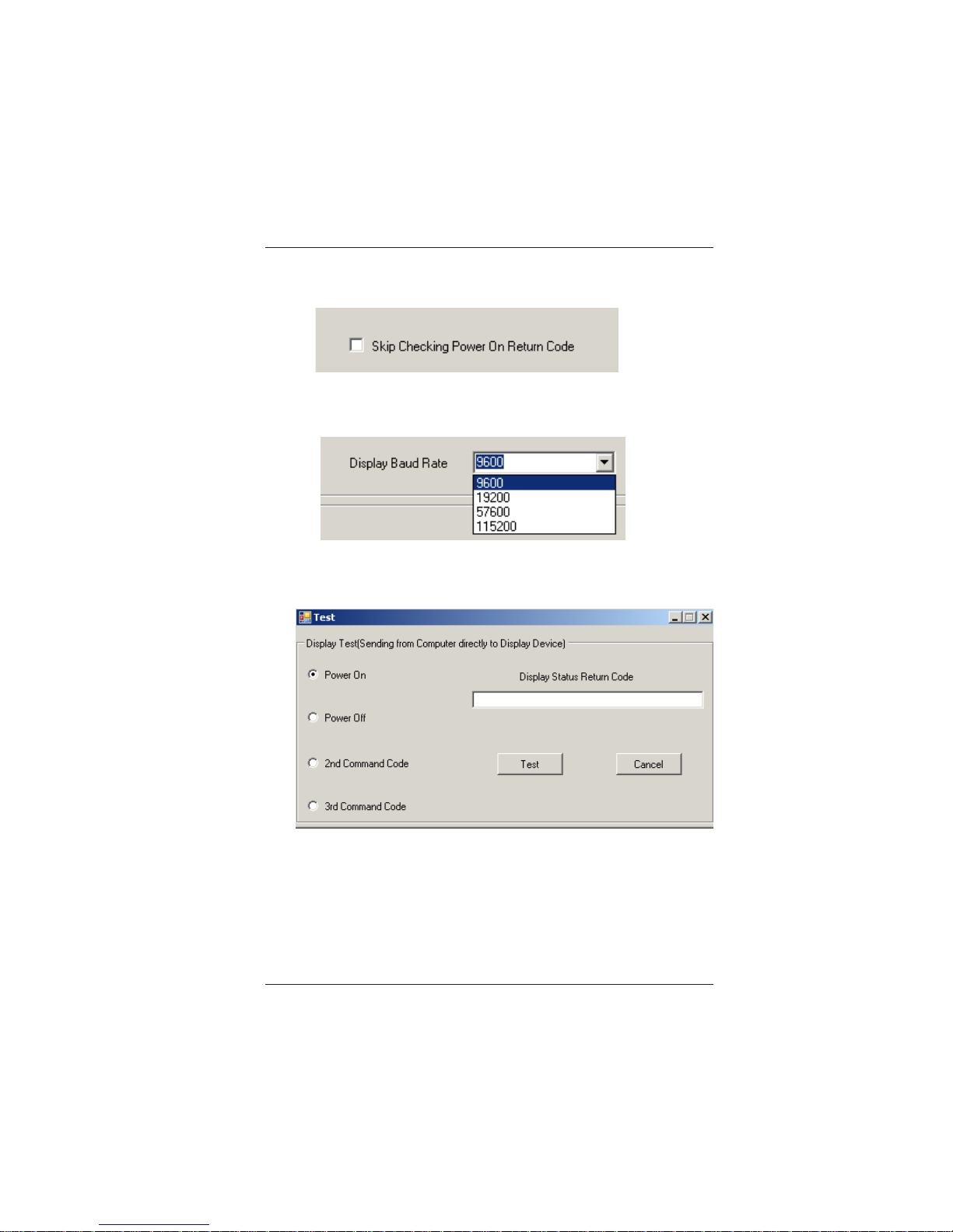
6. Select “Skip Checking Power On Return Code,” if not needed
7. From the Baud Rate pull down menu select the monitor
communication baud rate
8. As an optional step, one can use the T est pull down menu to bring
up the test dialog box and confirm the monitor functionality
Page 21
LBC-H/V-T -WP User’s Manual
Link Bridge
TM
HDMI/VGA Wall Plate Transmitter System
Broadata Technical Support, (800) 214-0222
22
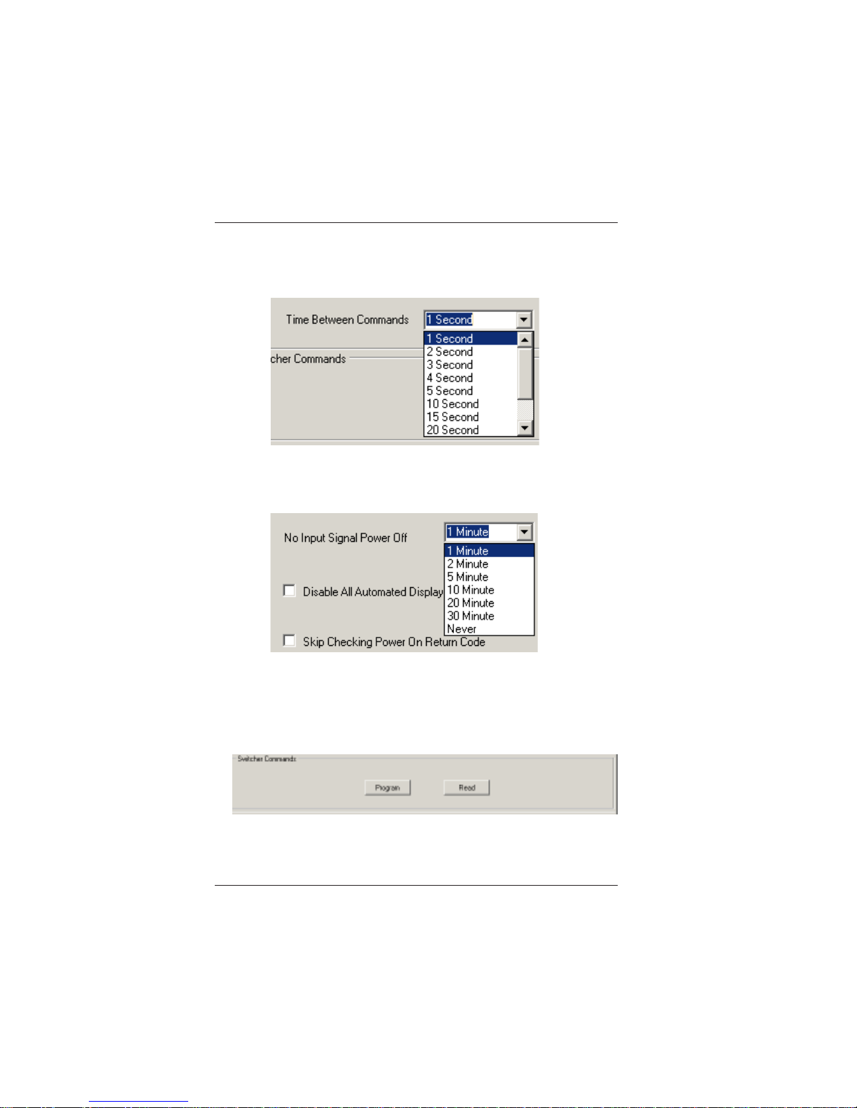
9. Select the “Time Between Commands” from the drop down window.
This sets the amount of time the controller will wait after it sends
the “Power On” command to send the 2nd and 3rd commands.
10. Select the “No Signal Power Off’ timeout from the drop down
windows
11. Click the ‘program’ button to save the automated settings into LBCH/V-T-WP, and click the ‘Read’ button to verify the automated
settings from LBC-H/V-T-WP
Page 22
LBC-H/V-T -WP User’s Manual
Link Bridge
TM
HDMI/VGA W all Plate Transmitter System
Broadata Technical Support, [email protected]
23
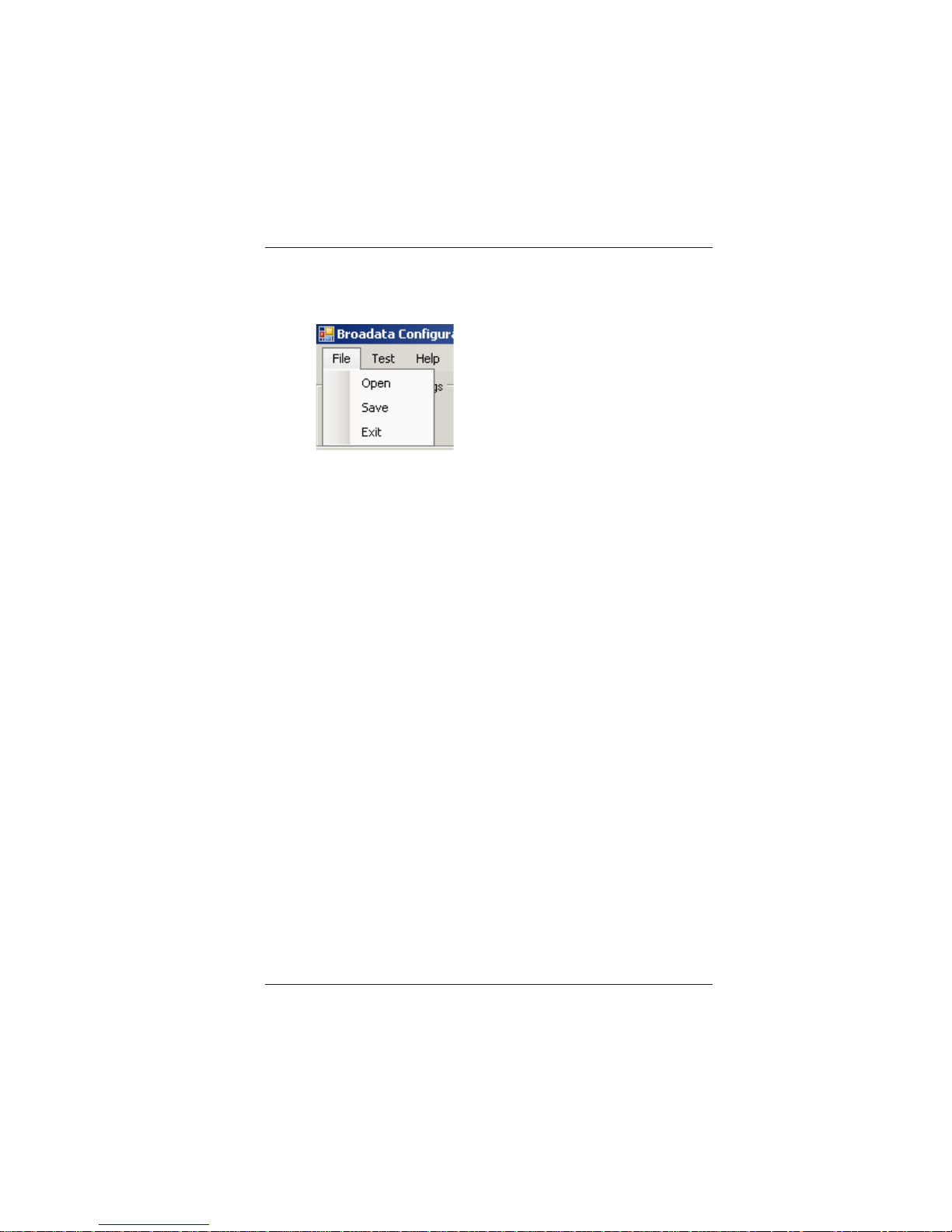
12. Save your configuration using the ‘File’ pull down menu.
Page 23

LBC-H/V-T -WP User’s Manual
Link Bridge
TM
HDMI/VGA Wall Plate Transmitter System
Broadata Technical Support, (800) 214-0222
24
6.0 MAINTENANCE AND TROUBLESHOOTING
6.1 Maintenance
There is no operator maintenance other then keeping the units
clean. However, observe the following light indicators to make
sure that the unit is working properly:
6.2 Troubleshooting
If the LBC-H/V-T-WP units do not operate properly after
installation, check for possible cable breaks, loose connections,
and incorrect cable connections. If problems persist that may
be fiber related, contact BCI at 1-800-214-0222 for further
assistance.
For electrical problems, perform the following troubleshooting
procedures:
1. If the POWER indicator is OFF , check for the following:
a. The line cord is plugged into the unit and your outlet
has power.
2. If the POWER indicator is ON, but the Link indicator is
OFF, check for the following:
a. Make sure the appropriate cables are being used.
b. Cable and cable connectors are not broken.
c. For each unit, the transmit (TX) cable is connected to
the other unit’s receiver (RX).
3. If the POWER indicator and Link indicator are ON, but
the channels are not operating, then:
a. Check to see that the attached user equipment is turned
on.
b. Both ends of the link are connected to the corresponding
equipment and to the same corresponding channel port.
Page 24

LBC-H/V-T -WP User’s Manual
Link Bridge
TM
HDMI/VGA W all Plate Transmitter System
Broadata Technical Support, [email protected]
25
c. Cable connections at both channels are securely
connected to each connector. T urn the power off, then
back on to reset the link.
Page 25

LBC-H/V-T -WP User’s Manual
Link Bridge
TM
HDMI/VGA Wall Plate Transmitter System
Broadata Technical Support, (800) 214-0222
26
7.0 SPECIFICATIONS
Video
Resolution* Up to 4K2K and 1080p @ 60Hz or
1920x1200 @ 60Hz
Connector HDMI Female Plug/ HD-15 VGA
Protocol DDC/EDID/HDCP Compatible
Transmission
Cable Type Single CA T 5e/6
Number of cables 1
Connector RJ45
Max Distance 70m (230 ft)
Physical
Dimension (H x W x D) 4.56" x 4.5" x 1.55" W all Plate
Power Level (max.) +24VDC @ 1A
LED Indicator Power/Link VGA/ HDMI
Operating Temperature 0 to +55oC
Humidity 5 to 95% RH, non-condensing
*Note: VGA input resolution is up to 1920x1200@60Hz
Page 26

LBC-H/V-T -WP User’s Manual
Link Bridge
TM
HDMI/VGA W all Plate Transmitter System
Broadata Technical Support, [email protected]
27
8.0 SERVICE PROCEDURE
8.1 Replacement Policy
Standard products found defective on arrival (DOA) will be
replaced, based on availability , within 24 to 48 hours anywhere
in the U.S. Please call Customer Service at 800-214-0222 for
information.
8.2 Return/Repair Service
The LBC-H/V-T-WP System contains no user serviceable
components. If you have a problem with your unit, please
contact the Customer Service Department. To facilitate our
return/repair processing please contact Broadata
Communications, Inc. to obtain a Return Material Authorization
(RMA). Please include the following information:
• Product model number
• Serial Number
• Complete description of problem
• Hardware installation description
Broadata Communications, Inc.
2545 West 237th Street, Suite K
Torrance, CA 90505
1-800-214-0222
(310) 530-1416
(310) 530-5958 (Facsimile)
e-mail: [email protected]
Website: www.broadatacom.com
Page 27

LBC-H/V-T -WP User’s Manual
Link Bridge
TM
HDMI/VGA Wall Plate Transmitter System
Broadata Technical Support, (800) 214-0222
28
9.0 LIMITED WARRANTY
Broadata Communications, Inc. (BCI) warrants, for a period of one
year from date of shipment, each product sold shall be free from defects
in material and workmanship. BCI will correct, either by repair, or at
BCI’s election, by replacement, any said products that in our sole
discretion prove to be defective and are returned to the manufacturing
location within 30 days after such defect is ascertained. All warranties
are limited to defects arising under normal use and do not include
malfunctions or failure resulting from misuse, abuse, neglect, alterations,
electrical power problems, usage not in accordance with product
instructions, improper installation, or damage determined by BCI to
have been caused by the Buyer or repair made by a third party . Limited
warranties granted on products are to the initial customer end-user and
are not transferable. OUR LIABILITY UNDER THIS W ARRANTY SHALL
IN ANY CASE BE LIMITED TO THE INVOICE VALUE OF THE
PRODUCT SOLD AND BCI SHALL NOT BE LIABLE TO ANYONE FOR
CONSEQUENTIAL OR INCIDENT AL DAMAGES ARISING FROM THE
USE OF ITS PRODUCTS OR THE SALE THEREOF. We make NO
WARRANTY AS TO THE MERCHANTABILITY OF ANY GOODS, OR
THAT THEY ARE FIT FOR ANY PARTICULAR PURPOSE OR END
APPLICA TION NOR DO WE MAKE ANY WARRANTY, EXPRESSED
OR IMPLIED OTHER THAN AS STA TED ABOVE.
Page 28

Broadata Communications, Inc.
2545 West 237th Street, Suite K
Torrance, CA 90505
1-800-214-0222
(310) 530-1416
(310) 530-5958 (Facsimile)
e-mail: [email protected]
Website: www.broadatacom.com
60000-LBC-H/V-T-WP
 Loading...