

Page 1
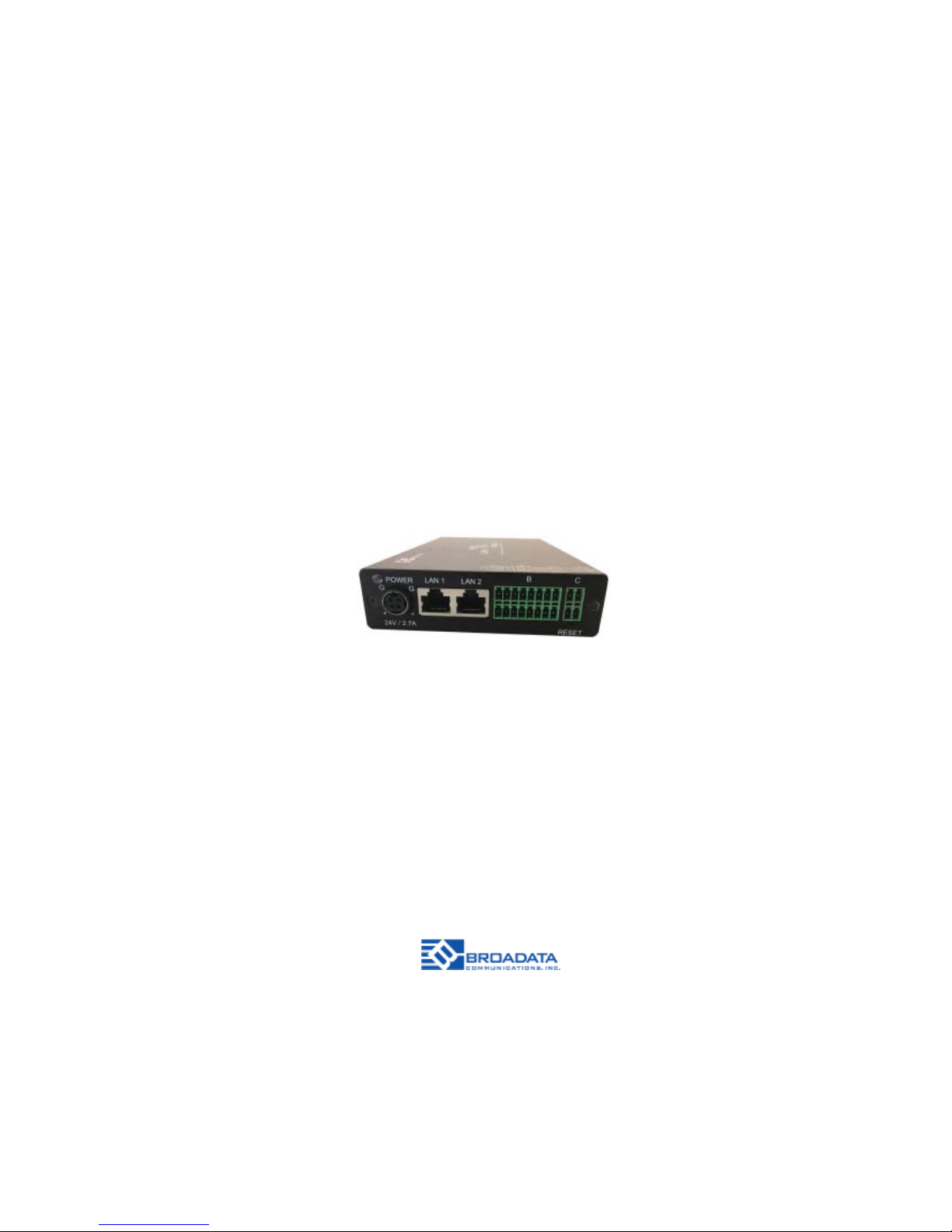
LBC-H/O-R-ICP
LINK BRIDGE
TM
HBASET/HDMI
RECEIVER WITH
INLINE CONTROL PROCESSOR
BCI reserves the right to make changes to the products described herein without prior
notice or consent. No liability is assumed as a result of their use or application. All
rights reserved.
©2015 Broadata Communications, Inc.
Page 2

LBC-H/O-R-ICP User Manual
Link Bridge
TM
HBaseT/HDMI Receiver w/Inline Control Processor
Broadata Technical Support, [email protected]
3
SAFETY INSTRUCTIONS AND
COMPLIANCE DECLARATIONS
PLEASE OBSERVE THE FOLLOWING SAFETY
PRECAUTIONS
SURGE PROTECTION DEVICE RECOMMENDED
This product contains sensitive electrical components that may be
damaged by electrical spikes, surges, electric shock, lightning strikes,
etc. Use of surge protection systems is highly recommended in order
to protect and extend the life of your equipment.
Page 3

LBC-H/O-R-ICP User Manual
Link Bridge
TM
HBaseT/HDMI Receiver w/Inline Control Processor
Broadata Technical Support, (800) 214-0222
4
TABLE OF CONTENTS
1.0 PRODUCT DESCRIPTION .............................................5
2.0 OPERATION CONTROL AND FUNCTIONS ...................6
2.1 RECEIVER EXTENDER FRONT AND REAR PANEL.....6
2.2 ICP FRONT AND REAR PANEL .....................................7
3.0 CONNECTOR PINOUT ASSIGNMENT ...........................8
3.1 EXTENDER ......................................................................8
3.1.1 SERIAL DA TA INTERF ACE............................................8
3.1.2 STATUS LEDS ...............................................................9
3.2 ICP .................................................................................10
3.3 LB-KP8 ...........................................................................11
4.0 LB-ICP WEB SERVER DESCRIPTION .........................13
5.0 SPECIFICA TIONS...........................................................39
6.0 SERVICE PROCEDURE ................................................42
6.1 REPLACEMENT POLICY ..............................................42
6.2 RETURN AND REPAIR SERVICE .................................42
7.0 LIMITED WARRANTY ....................................................43
Page 4

LBC-H/O-R-ICP User Manual
Link Bridge
TM
HBaseT/HDMI Receiver w/Inline Control Processor
Broadata Technical Support, [email protected]
5
1.0 PRODUCT DESCRIPTION
Overall
• A selectable HDBT or HDMI receiver with multiple control I/O
ports
• Provides in-line control I/O paths
Receiver
• Receive HDMI, audio, IR, and RS-232 up to 100 meters over 1
CA T-5e/6 cable
• Supports video resolutions up to 1080p 60Hz and
1920 x 1200@60Hz, as well as 4K@30Hz
• Optional 1080p scaler
• Supports HDMI w/embedded audio extraction
• EDID pass-through support, automatically detects the factory
setting of the connected display
• HDCP 2.2 support
Control
• Control I/O ports contain:
- three (3) RS-232
- two (2) Relay
- two (2) Digital I/O
- one (1) IR
- one (1) Ethernet
• Control and monitor A V devices using a standard Ethernet
network (Smart phone or PC) or RS-232 (keypad)
• Front panel port status indicators
• User friendly customizable control configurations via built-in
web server
Page 5
LBC-H/O-R-ICP User Manual
Link Bridge
TM
HBaseT/HDMI Receiver w/Inline Control Processor
Broadata Technical Support, (800) 214-0222
6
2.0 OPERATION CONTROLS AND FUNCTIONS
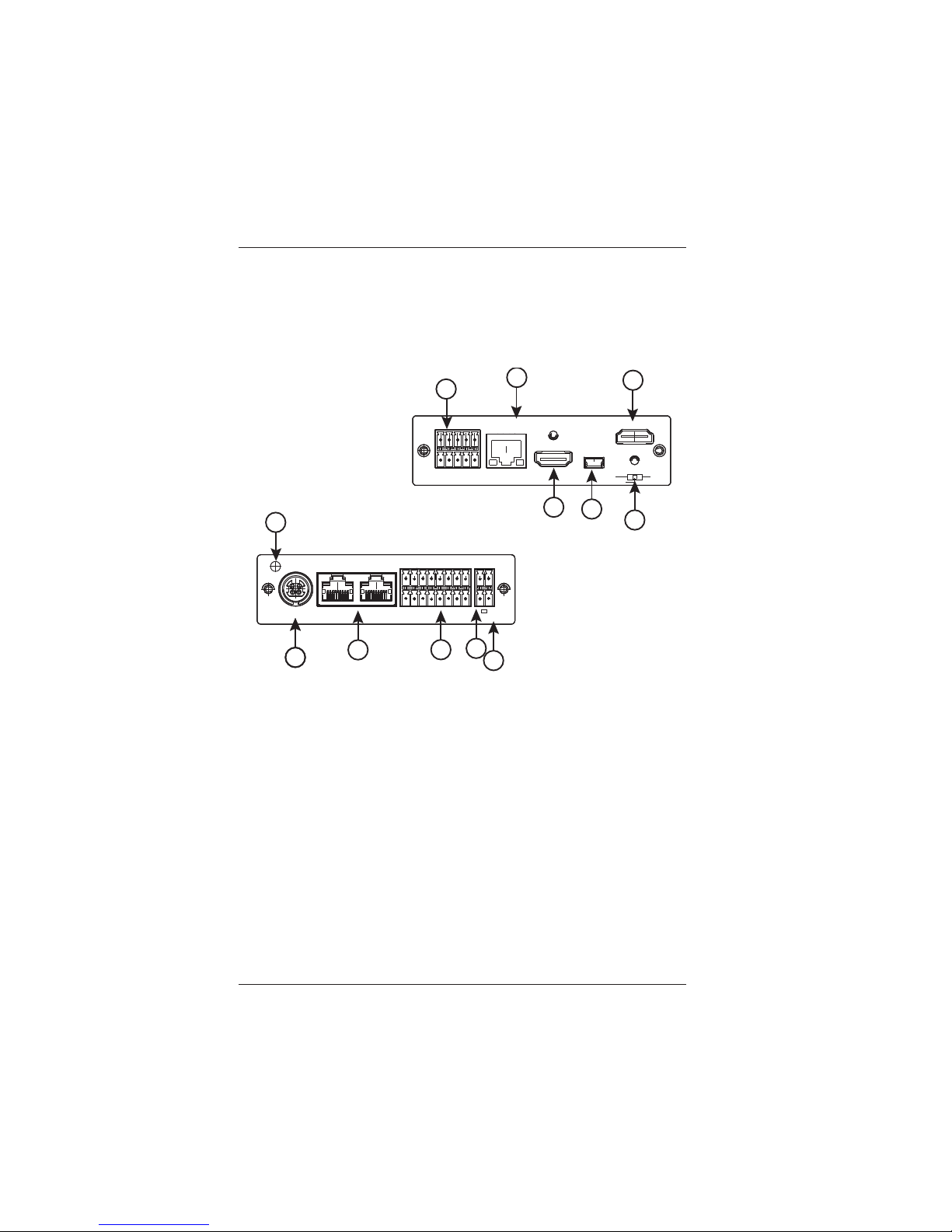
2.1 Receiver Front and Rear Panel
1. HDMI Input connector – Connect an HDMI cable from this
port to the HDMI output port of the video source. The
connected source can be selected to be displayed on the
HDMI Output connector.
2. HDMI Output connector – Connect an HDMI cable from
this port to the HDMI input port of the display .
3. HDBT RJ-45 connector – Connect a CA T5e/6/7 cable from
this port to the HDBT output port of a compatible transmitter .
The yellow LED indicates that the unit has a good HDBT
connection with the transmitter. The green LED indicates
the port is active.
POWER
LAN 1
LAN 2
24V/2.7A
RESET
B
C
G
G
++
7
8
9
10
11
12
Rear
CAT5e/6/7 IN
HDMI IN
HDMI OUT
CONFIG
HDBT
AUDIO
HDMI
VIDEO IN
A
LBC-H/O-R-ICP
4
1
5
6
2
3
Fron
t
Page 6

LBC-H/O-R-ICP User Manual
Link Bridge
TM
HBaseT/HDMI Receiver w/Inline Control Processor
Broadata Technical Support, [email protected]
7
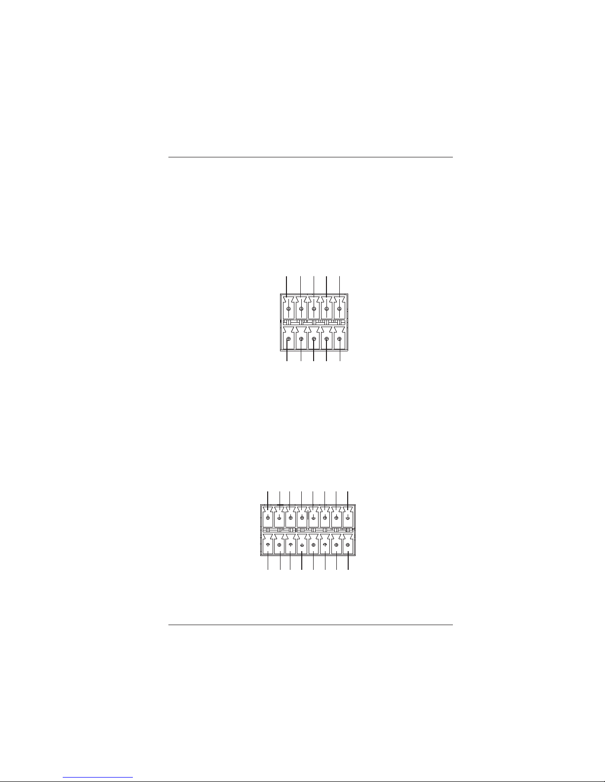
4. Terminal Block A
Audio In L/R - Connect a stereo audio source to the Audio
In (L), Audio In (R) and GND pins. This audio input can be
selected as a source for the Audio Out.
Audio Out L/R - Connect the Audio Out (L), Audio Out (R)
and GND to the audio input of the receiver/amp. The Audio
output can be the de-embedded HDMI audio or Audio Input.
Relay 1 - Connect to a device for relay control. N/O is
normally open with respect to COM.
IR+/IR- : Connect to an IR blaster. The IR port can transmit
internally stored IR codes or act as an IR pass-through.
5. Configuration connector – Connect a PC to this connector
to update the firmware.
6. Video In switch – Select Auto for normal operation. Select
HDBT to manually select the video from the transmitter.
Select HDMI to manually select the video from the local
HDMI Input.
7. Power input connector – Connect to the included +24V
supply.
8. Power LED – The green LED indicates the unit is powered
up.
9. LAN 1 & LAN 2 RJ-45 connectors - Connect a CA Tx cable
from either LAN 1 or LAN 2 port to a LAN connection. The
LAN connection will pass-through to the transmitter.
Conversely , if the LAN port of the transmitter is connected
to a LAN connection, the LAN connection will pass-through
to LAN 1 and LAN 2 ports.
Page 7

LBC-H/O-R-ICP User Manual
Link Bridge
TM
HBaseT/HDMI Receiver w/Inline Control Processor
Broadata Technical Support, (800) 214-0222
8
10. Terminal Block B
Relay 2 – Connect to a device for relay control. N/O is
normally open with respect to COM.
Digital IO 1 & 2 – Each digital IO can be configured as an
input or output. When configured as an input, the digital
input can be used as a contact closure input to trigger
automated actions. When configured as an output, the
digital output can drive a 5V TTL level signal to an external
device.
RS-232 1, 2, 3 & 4 - Connect the Tx, Rx and GND pins to
the Rx, Tx and GND pins, respectively , of the device to be
controlled. RS-232 Ch-4 is a control channel by default,
but can be configured as a pass-through channel.
+24V Out – Connect to an external device that requires
+24V power, such as an occupancy sensor.
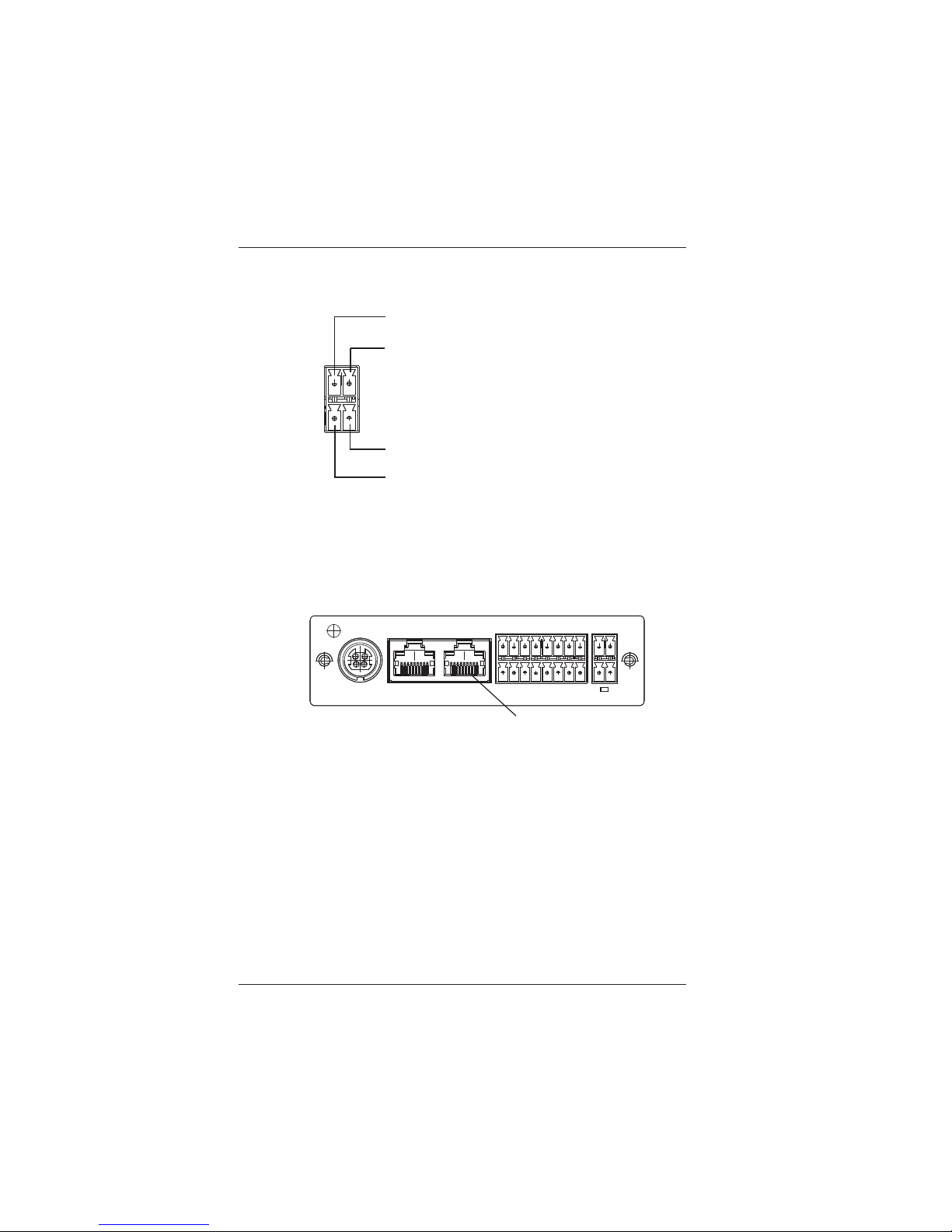
11. Terminal Block C
Connect a cable, terminated per Figure 3-5, in order to
connect to an LB-KP8/LB-KP4 keypad.
12. Reset button – Press button to reset unit to factory default
settings.
Page 8
LBC-H/O-R-ICP User Manual
Link Bridge
TM
HBaseT/HDMI Receiver w/Inline Control Processor
Broadata Technical Support, [email protected]
9
3.0 CONNECTOR PINOUT ASSIGNMENT
3.1 T erminal Block A
3.2 Terminal Block B
Audio IN (L)
Audio IN (R)
GND
Audio OUT (L)
Audio OUT (R
)
(Optional)
Relay 1 COM
Relay 1 N/O
IR -
IR +
(Front view)
Digital I/O 2
+24V (OUT)
Digital I/O 1
RS-232 1 RX
RS-232 1 TX
GND
RS-232 2 RX
RS-232 2 TX
(Optional)
Relay 2 COM
Relay 2 N/O
RS-232 3 RX
RS-232 3 TX
RS-232 4 RX
RS-232 4 TX
GND
(Front view)
Page 9
LBC-H/O-R-ICP User Manual
Link Bridge
TM
HBaseT/HDMI Receiver w/Inline Control Processor
Broadata Technical Support, (800) 214-0222
10
3.3 Terminal Block C
3.4 LAN 1 and 2
RS-232 OUT (Orange)
+12V OUT (Blue)
RS-232 IN (White/Orange)
GND (Brown)
RJ-45
1 - TX+
2 - TX3 - RX+
4 - N/C
5 - N/C
6 - RX7 - N/C
8 - N/C
POWER
LAN 1
LAN 2
24V/2.7A
RESET
B
C
G
G
++
Rear
Page 10
LBC-H/O-R-ICP User Manual
Link Bridge
TM
HBaseT/HDMI Receiver w/Inline Control Processor
Broadata Technical Support, [email protected]
11
3.5 LB-KP8/LB-KP4
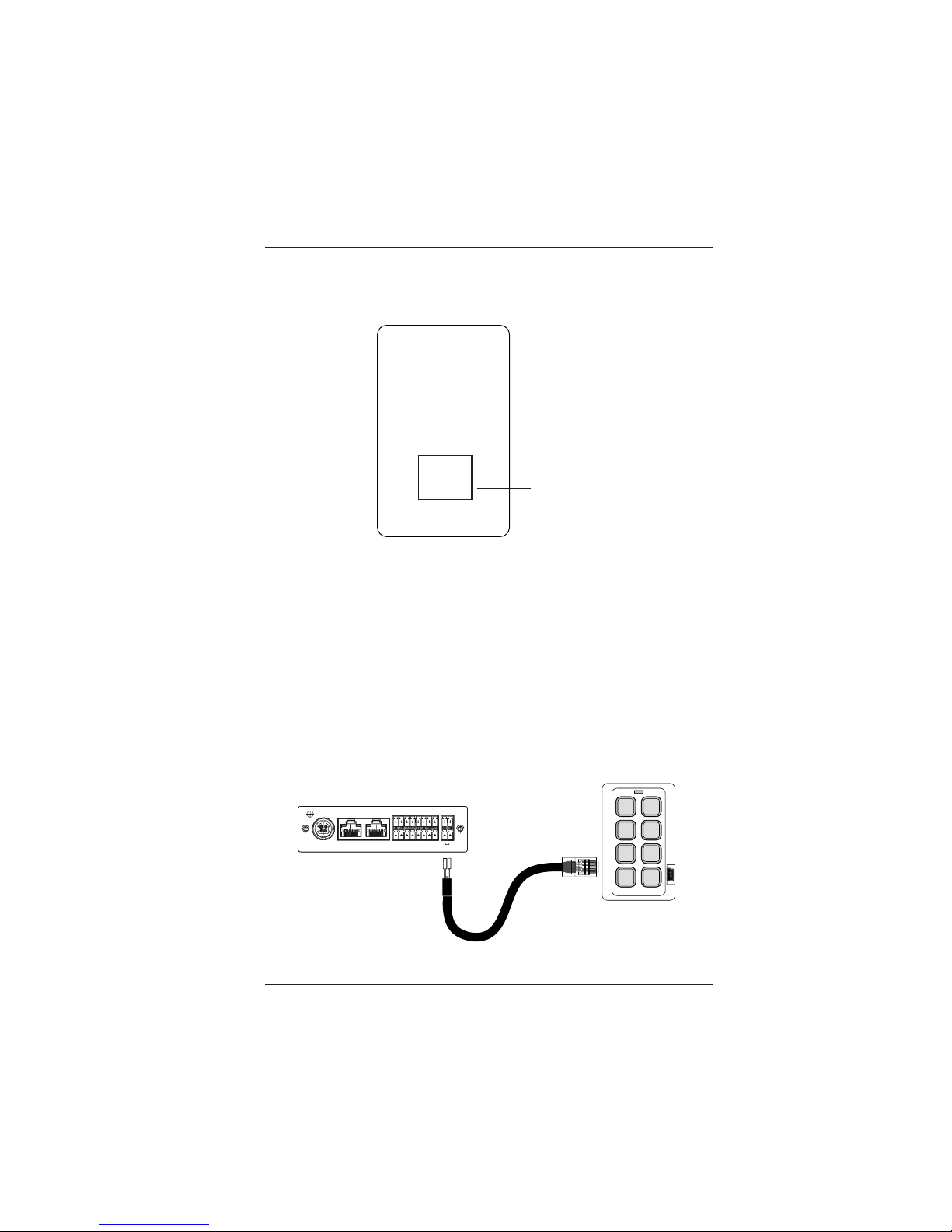
The cable connection between LB-KP8 and LB-ICP is shown below .
Rear
Control
RJ-45
Pin 1: RS-232 OUT
Pin 2: RS-232 IN
Pin 3: --no connect-Pin 4: +12v
Pin 5: +12v
Pin 6: --no connect-Pin 7: GND
Pin 8: GND
Standard RJ45
Terminat ion T-568B
2. Whit e / Orang e (RS2 3 2 In )
3. Orang e (RS23 2 Out)
1. Blue (+12V)
4. Brown (Ground)
1. Whit e/Orange
2. Orange
3. Whit e/Green
4. Blue
5. Whit e/Blue
6. Green
7. Whit e/Brown
8. Brown
POWER
LAN 1
LAN 2
24V/2.7A
RESET
B
C
G
G
++
Page 11
LBC-H/O-R-ICP User Manual
Link Bridge
TM
HBaseT/HDMI Receiver w/Inline Control Processor
Broadata Technical Support, (800) 214-0222
12
4.0 LB-ICP WEB SERVER DESCRIPTION
Introduction
The ICP Web Server provides user friendly and intuitive web pages to
configure the virtual keypad and automation functions within the ICP. It
also provides web pages to control video switching, audio settings and
manage IR code import. A standard web browser can be used to access
the web pages.
Accessing Web Server
The IP address of the ICP must be obtained in order to access the Web
Server. There are 2 ways to obt ain the IP address of an ICP.
1) Use the IPCONFIG command in the Configuration Port
Command Line Interface to display the unit’s IP address.
2) Use the BCI PC Configuration Program.
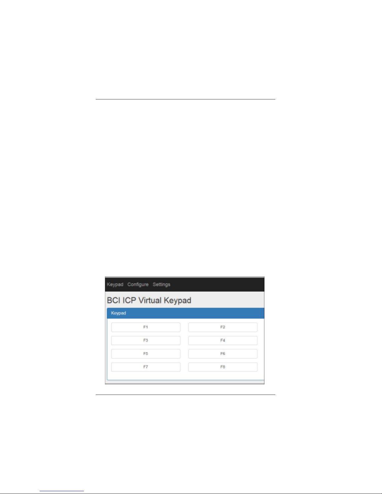
Type in the unit’s IP address in the web browser. The ICP Virtual
Keypad page will be displayed. All 8 keys of the Virtual Keypad are unprogrammed by default. The keys are configured in the Configure
Keypad Control page.
Page 12
LBC-H/O-R-ICP User Manual
Link Bridge
TM
HBaseT/HDMI Receiver w/Inline Control Processor
Broadata Technical Support, [email protected]
13
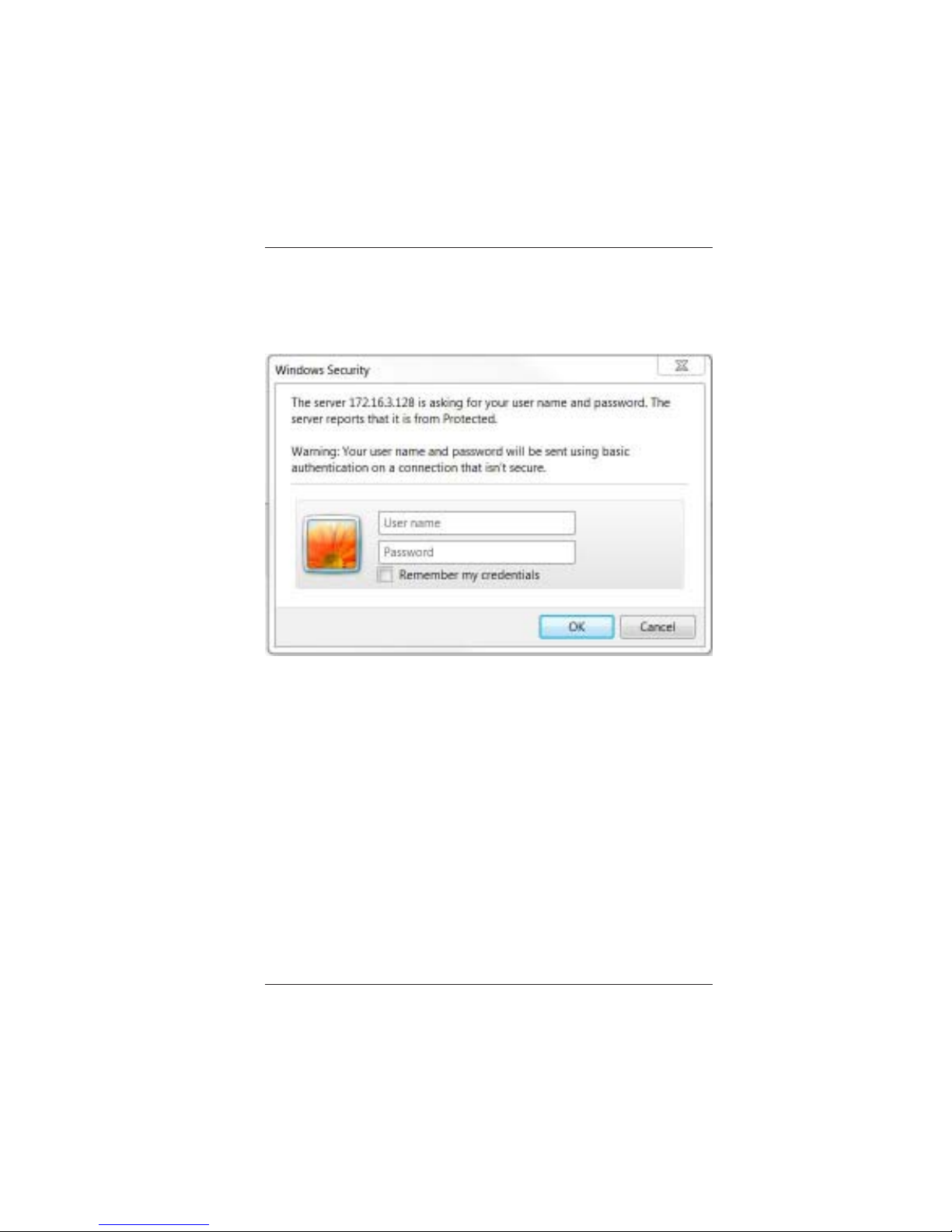
Before configuring the Virtual Keypad, the system first needs to be set
up using the Configure System page. On the top menu bar, click
Configure and then click System. This brings up the ICP Login.
In the ICP Login type in admin for the User name and admin for the
Password and then click OK button. The Configure System page will
appear. See the following section for Configure System page details.
Once logged in, the user is free to open any of the Configure or Settings
pages. The default Password can be changed using the BCI Product
Configuration program.
Page 13
LBC-H/O-R-ICP User Manual
Link Bridge
TM
HBaseT/HDMI Receiver w/Inline Control Processor
Broadata Technical Support, (800) 214-0222
14
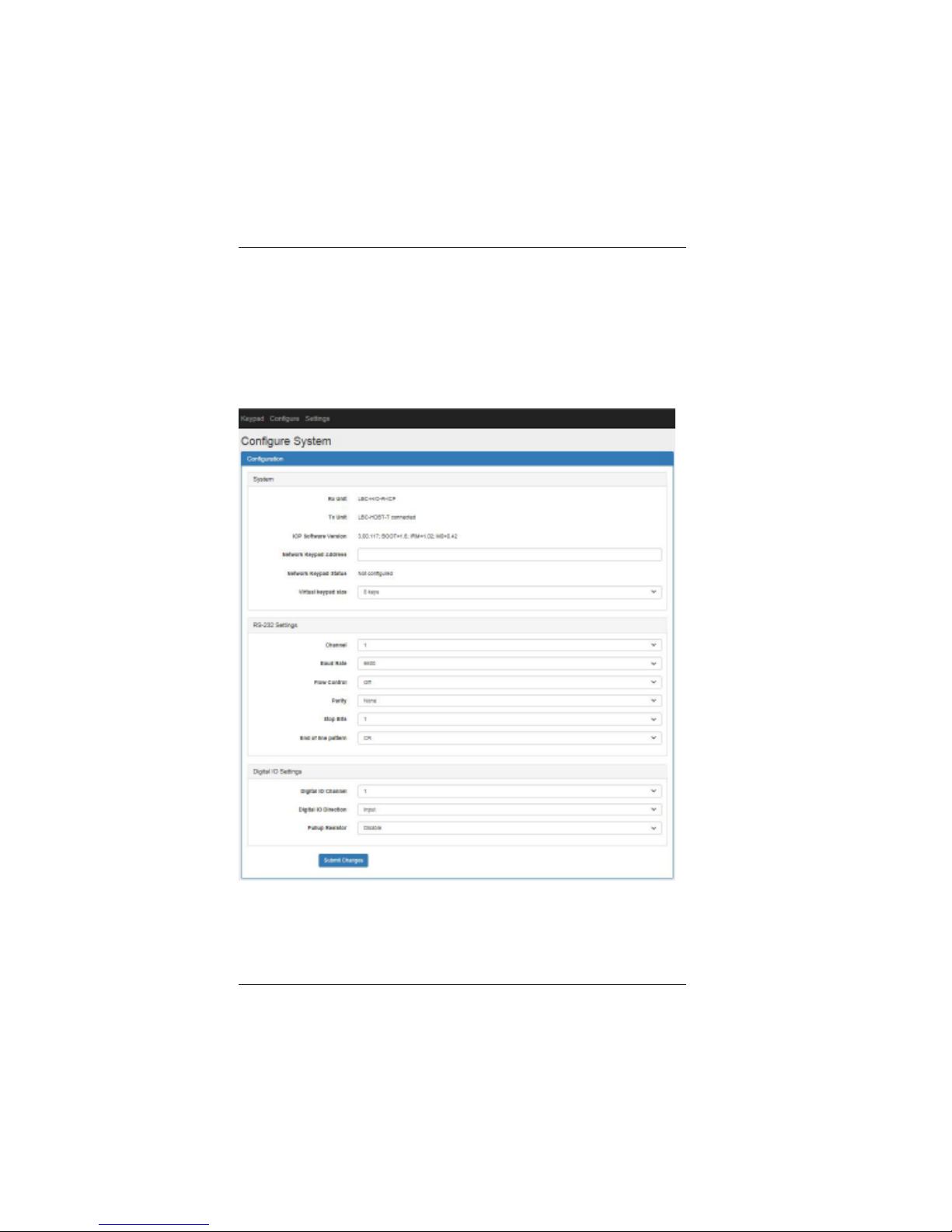
Configure System
The Configure System page is used to configure the network keypad,
virtual keypad, RS-232 channels, and Digital IO channels.
On the top menu bar, click Configure and then click System. The
following page will be displayed:
Page 14

LBC-H/O-R-ICP User Manual
Link Bridge
TM
HBaseT/HDMI Receiver w/Inline Control Processor
Broadata Technical Support, [email protected]
15
System
The first three lines in this panel show the LBC-H/O-R-ICP model number ,
the Tx unit model number if one is connected and the software version.
Below that is the address setup and status for the Network Keypad.
There is a pull-down menu for selecting the virtual keypad.
Rx Unit: Shows the LBC-H/O-R-ICP model number.
Tx Unit: Shows Tx model number and connection status.
Network Keypad Address: Enter the IP address of the network keypad
(LB-KP8E or LB-KP16E) if one is present in the system. Use the BCI
Product Configuration program to discover the network keypad’s IP
address.
Network Keypad Status: Shows type of network keypad connected
to ICP .
Virtual Keypad Size: Select 8 keys or 16 keys. 8 keys option:
maximum of 10 actions per key . 16 keys option: maximum of 5 actions
per key .
RS-232 Settings
This panel is used to configure the RS-232 channels.
Channel: Select channel 1, 2, 3, 4 or 5 (Tx). Channel 4 can be
configured to operate in control (ICP) or pass-through mode. If passthrough mode is selected, channel 5 (RS-232 port in the Tx) will passthrough to channel 4. Channel 4 and 5 can no longer be used as control
channels.
Baud Rate: Select a baud rate from 9600 to 115200 baud.
Flow Control: Select On to enable flow control and Off to disable flow
control. Flow control is available only on Channel 1. If flow control is
enabled, Channel 2 is no longer available.
Page 15

LBC-H/O-R-ICP User Manual
Link Bridge
TM
HBaseT/HDMI Receiver w/Inline Control Processor
Broadata Technical Support, (800) 214-0222
16
Parity: Select None, Odd or Even.
Stop Bits: Select 1 or 2.
End of Line Pattern: Select CR, LF, CR+LF or None for end of line
termination.
Digital IO Settings
The 3 pull down menus in this panel are used to configure the Digital IO
settings. Digital IOs are inputs by default and show up as triggers in the
Configure Auto Actions page.
Digital IO Channel: Select channel 1 or 2.
Digital IO Direction: Select channel as a digital Input or Output.
If the Digital IO Direction is set to Input, there is an option for Pullup
Resistor.
Pullup Resistor: Select Enable or Disable pull-up resistor.
Page 16
LBC-H/O-R-ICP User Manual
Link Bridge
TM
HBaseT/HDMI Receiver w/Inline Control Processor
Broadata Technical Support, [email protected]
17
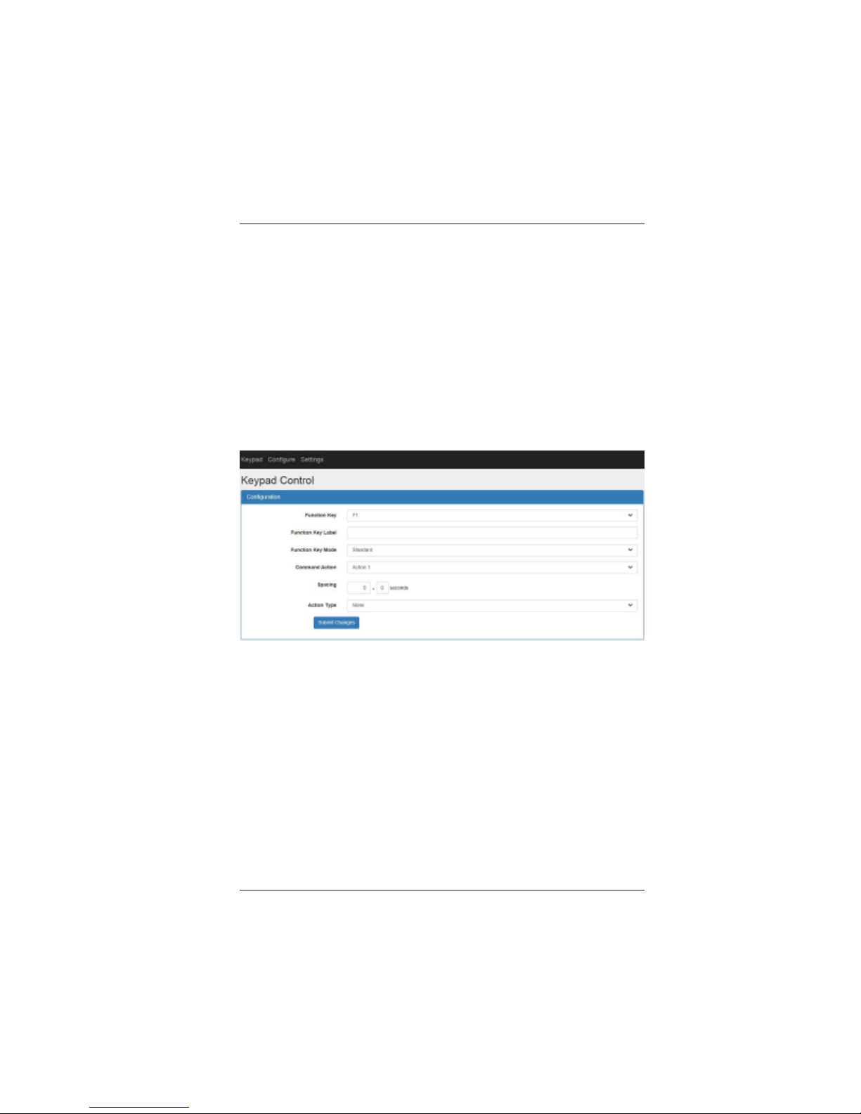
Configure Key Action
The Configure Key Action page is used to configure the keys on the
virtual keypad. On the 8-key keypad, each function key can be defined
as a macro for up to 10 different actions. On the 16-key keypad, each
function key can be defined as a macro for up to 5 actions. The available
actions are Relay, Digit al Output, RS-232, IR, T elnet, V ideo Input Select
and Keypad. Note: Digital Output actions are only available if Digital
IOs are configured as outputs in the Configure System page.
On the top menu click Configure and then click Keypad Control. The
following page will be displayed:
Function Key: Select the function key F1 through F8 to be defined.
Function Key Label: Type in a label name for the selected function
key.
Function Key Mode: Select Standard for a “momentary” type key.
Only one set of actions is assigned to a Standard key. Select Toggle
for a “toggle” type key . A Toggle key has two states: Press and Release.
One set of actions is assigned to the Press state and another set of
actions is assigned to the Release state.
Command Action: Select the action number to be defined. Action 1
through Action 10 can be defined.
Page 17
LBC-H/O-R-ICP User Manual
Link Bridge
TM
HBaseT/HDMI Receiver w/Inline Control Processor
Broadata Technical Support, (800) 214-0222
18
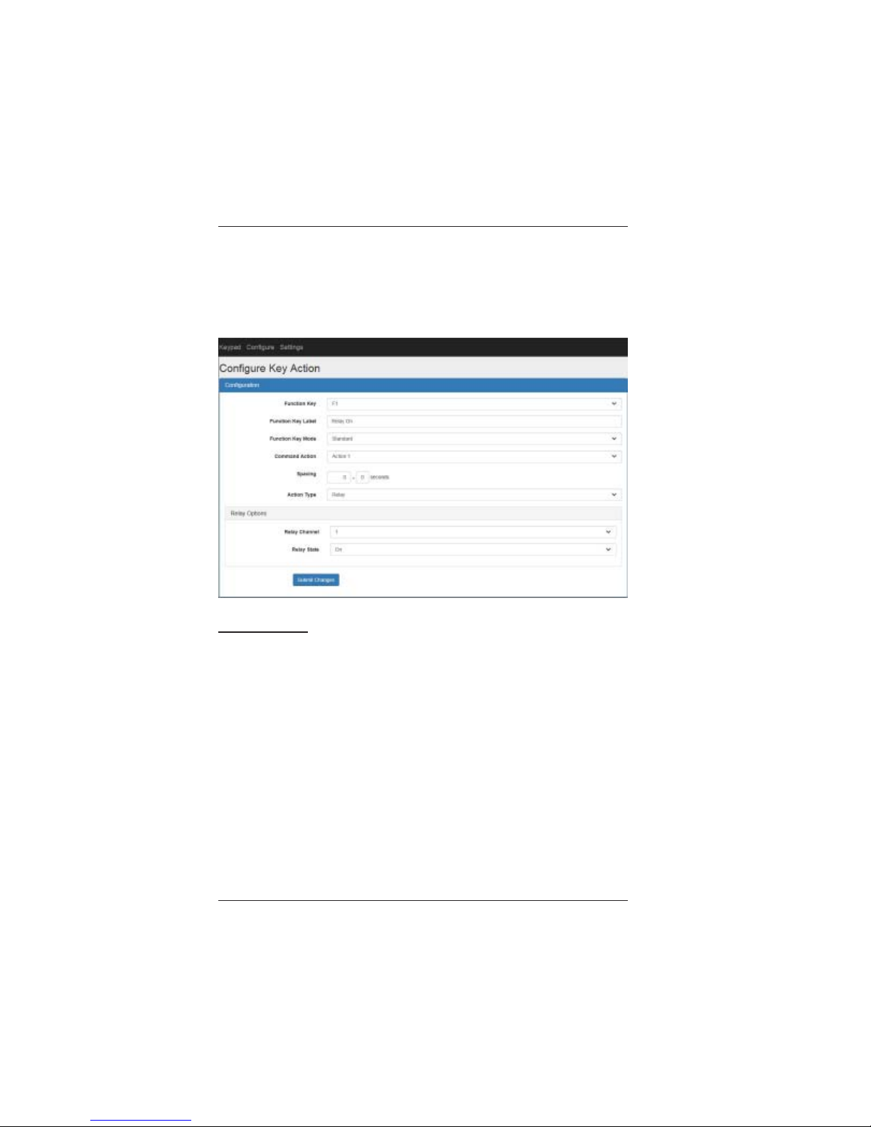
Spacing: Enter the delay desired before the command action.
Action Ty pe: Select the action type. A vailable types are None, Relay,
Digital Output, RS-232, IR, T elnet, Keyp ad, Video Control and Audio
Control.
Relay Options
Relay Channel: Select the relay channel 1 or 2.
Relay State: Select the relay channel state, On (energized) or Off (de-
energized).
Page 18
LBC-H/O-R-ICP User Manual
Link Bridge
TM
HBaseT/HDMI Receiver w/Inline Control Processor
Broadata Technical Support, [email protected]
19
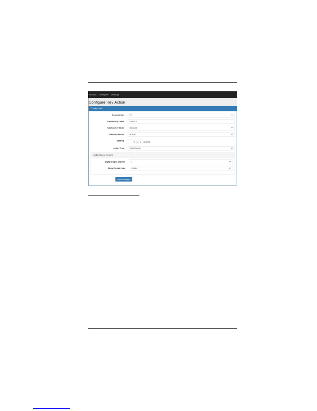
Digital Output Options
Digital Output Channel: Select the digital output channel 1 or 2.
Note: this option is not available if both Digital IO channels are set to
Inputs in Configure System page.
Digital Output State: Select the digital output state: 1 (High) or 0
(Low).
Page 19
LBC-H/O-R-ICP User Manual
Link Bridge
TM
HBaseT/HDMI Receiver w/Inline Control Processor
Broadata Technical Support, (800) 214-0222
20
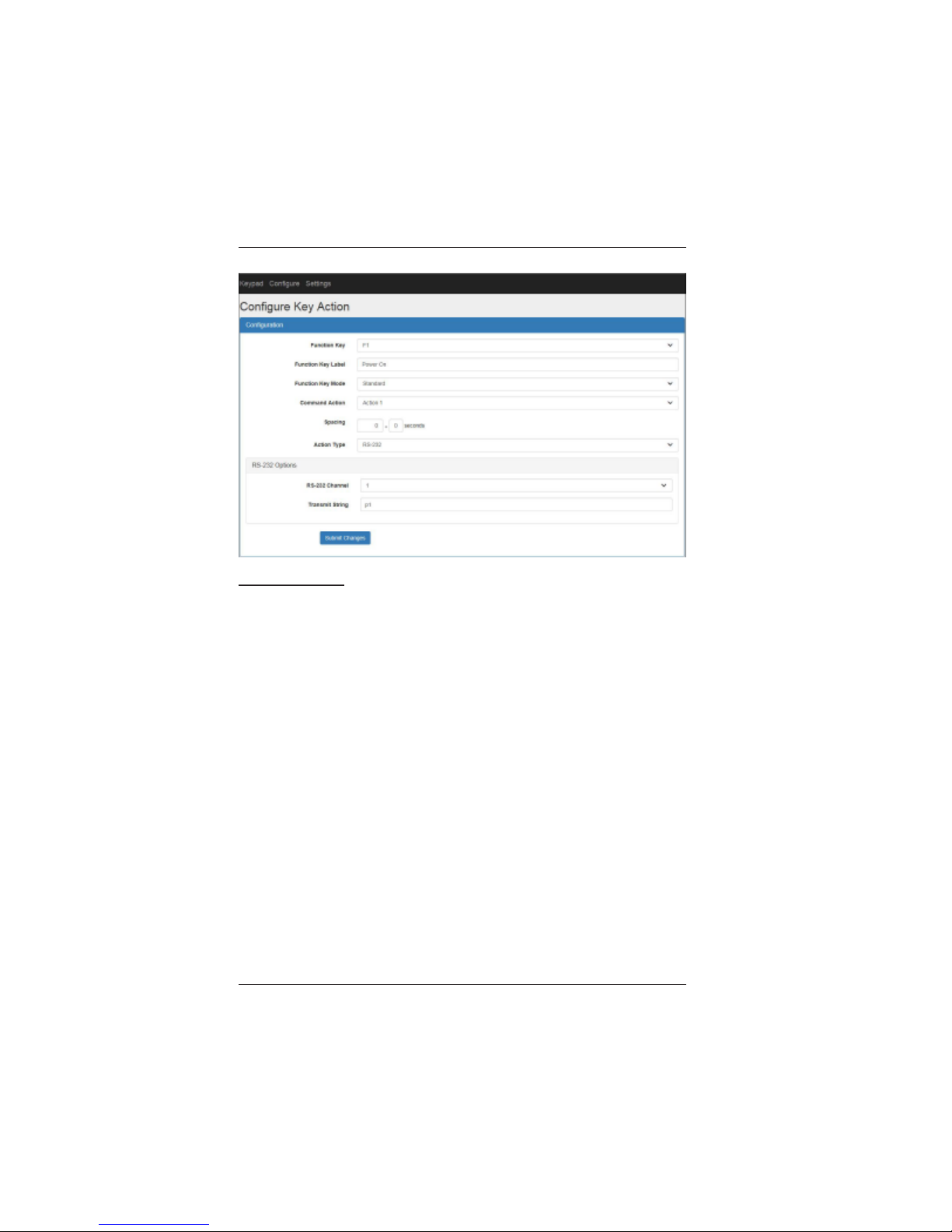
RS-232 Options
RS-232 Channel: Select channel 1, 2, 3, 4 or 5 (Tx).
Transmit String : T ype in the text string to be transmitted. S trings are
terminated with CR, CR+LF or no termination, depending on the selection
made in Configure System page. Characters enclosed by <> will be
treated as hex. For example to transmit the string “8C 00 00 02 00 8E”
in hex, enter <8C><00><00><02><00><8E>.
Page 20
LBC-H/O-R-ICP User Manual
Link Bridge
TM
HBaseT/HDMI Receiver w/Inline Control Processor
Broadata Technical Support, [email protected]
21
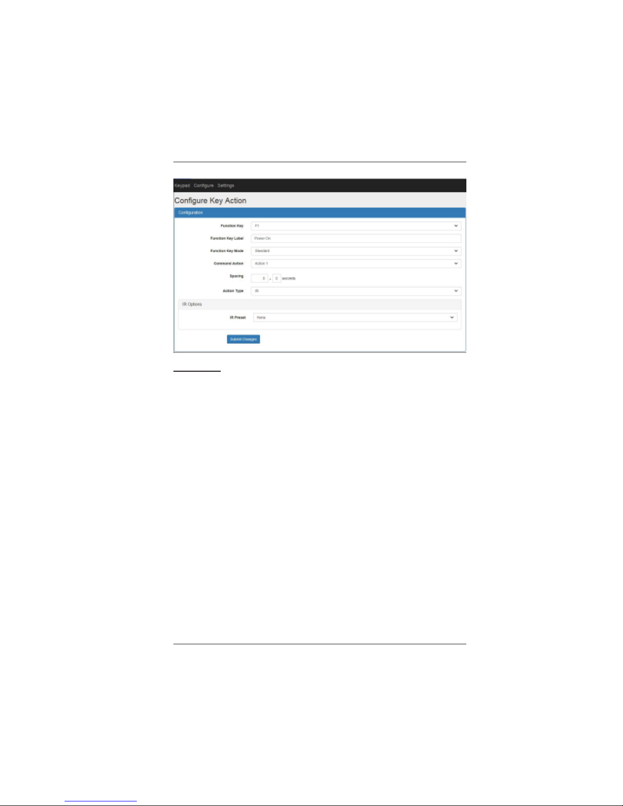
IR Options
IR Preset: Select from list of IR commands stored in memory. IR
commands can be imported via Configure IR Code Import page.
Page 21
LBC-H/O-R-ICP User Manual
Link Bridge
TM
HBaseT/HDMI Receiver w/Inline Control Processor
Broadata Technical Support, (800) 214-0222
22
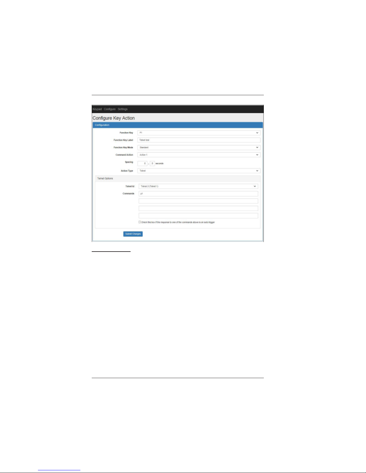
Telnet Options
T elnet ID: Select the telnet connection desired for telnet actions. The
connections defined in Configure Telnet Connections page appear in
this menu.
Commands: Enter the command strings to be transmitted. Up to 4
different command strings can be defined. The combined maximum
number of characters for all 4 strings is 100.
Select the check box if the response to one of the commands is to be
used as an auto trigger.
Page 22
LBC-H/O-R-ICP User Manual
Link Bridge
TM
HBaseT/HDMI Receiver w/Inline Control Processor
Broadata Technical Support, [email protected]
23
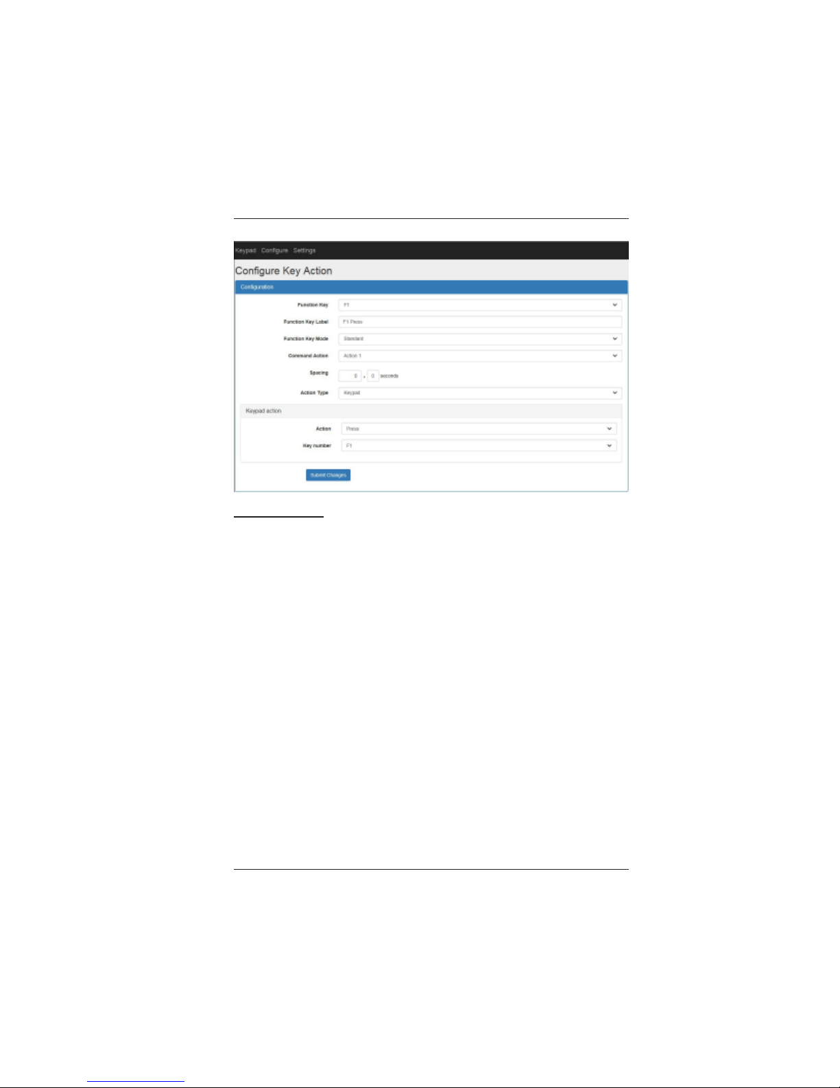
Keypad Action
Action: Select Press, Release, Press (no actions), Release (No
actions), Release All Toggle Buttons, Lock Buttons or Unlock Buttons.
Press: This action presses the key selected in Key Number menu. All
associated actions for the key press state will be executed.
Release: This action releases the key selected in Key Number menu.
All associated actions for the key release state will be executed.
Press (no actions will be triggered): This action presses the key
selected in Key Number menu, but none of associated actions for the
key press state will be executed.
Release (no actions will be triggered): This action releases the key
selected in Key Number menu, but none of associated actions for the
key release state will be executed.
Release All Toggle Buttons: This action sets all toggle keys to the
release state without executing any actions.
Page 23
LBC-H/O-R-ICP User Manual
Link Bridge
TM
HBaseT/HDMI Receiver w/Inline Control Processor
Broadata Technical Support, (800) 214-0222
24
Lock Buttons: This action locks designated buttons so that they
become inactive.
Unlock Buttons: This action unlocks designated buttons that were
previously locked.
Key Number: Select a key number for the selected keypad action.
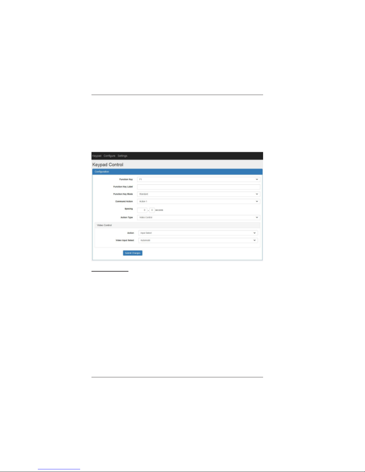
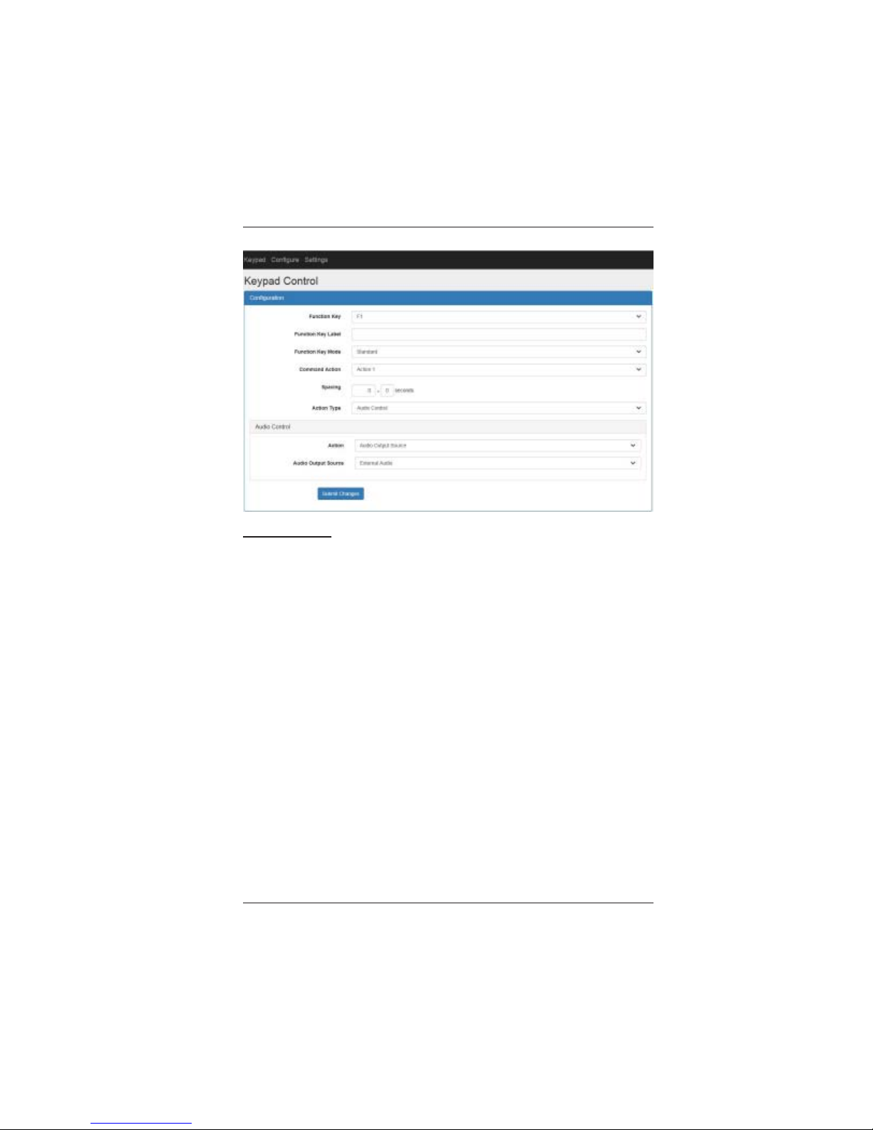
Video Control
Action: Select Input Select, Output On, Output off
Input Select: This action selects automode (auto switching) or manually
selects the Tx HDMI (HDBT) or local HDMI.
Output On: This action turns on the video output.
Output Off: This action turns off the video output.
Page 24
LBC-H/O-R-ICP User Manual
Link Bridge
TM
HBaseT/HDMI Receiver w/Inline Control Processor
Broadata Technical Support, [email protected]
25
Audio Control
Action: Select Audio Output Source, HDMI Audio Mute, HDMI Audio
Unmute, Analog Audio Mute, Analog Audio Unmute, Volume Up, Volume
Down, Set Volume.
Audio Output Source: This action selects the source for the analog
audio output. HDMI Audio is the de-embedded audio from the HDMI
video. External Audio is the analog audio input. Mixer Output is the
audio mix of the HDMI and external audio.
HDMI Audio Mute: This action mutes the HDMI audio.
HDMI Audio Unmute: This action unmutes the HDMI audio.
Analog Audio Mute: This action mutes the analog audio output.
Analog Audio Unmute: This action unmutes the analog audio output.
V olume Up: This action increases the analog audio output volume by
one step.
Page 25
LBC-H/O-R-ICP User Manual
Link Bridge
TM
HBaseT/HDMI Receiver w/Inline Control Processor
Broadata Technical Support, (800) 214-0222
26
V olume Down: This action decreases the analog audio output volume
by one step.
Set Volume: This action sets the analog audio output volume to a
specific level between 0 and 80.
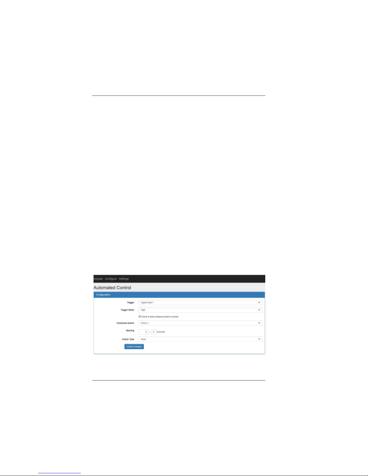
Configure Automated Control
The Configure Automated Control page is used to configure a set of
automated actions based on a selected trigger. Available triggers are
Video Detects (Local HDMI, Remote HDMI and Combined), Digital Input
1, Digital Input 2, RS-232 Channel 1, RS-232 Channel 2, T elnet Trigger
1 and Telnet Trigger 2. The available actions are Relay, RS-232, IR,
T elnet, Keypad, V ideo Control and Audio Control. Digit al Output actions
are only available if Digital IOs are configured as outputs in the Configure
System p age. All auto triggers work independently and can be triggered
simultaneously.
On the top menu click Configure and then click Automated Control.
The following page will be displayed:
Page 26

LBC-H/O-R-ICP User Manual
Link Bridge
TM
HBaseT/HDMI Receiver w/Inline Control Processor
Broadata Technical Support, [email protected]
27
Trigger: Select the auto action trigger. Available triggers are Video
Detect (Local HDMI), Video Detect (Remote HDMI), Video Detect
(DisplayPort), Digital Input 1, Digital Input 2, RS-232 Channel 1, RS-232
Channel 2, T elnet Trigger 1 and Telnet Trigger 2.
Trigger When: For Digital Input s, select High for the High signal trigger.
Select Low for the Low signal trigger. For the Video Detect lines, the
trigger options are when Video Detect line is Asserted or De-asserted.
For RS-232 triggers, enter the trigger string. Up to 2 trigger strings can
be defined for each RS-232 channel. For Telnet triggers, select the
telnet trigger and enter the trigger string. Up to 2 trigger strings can be
defined for each T elnet trigger .
Note: A telnet trigger needs to be associated with one or more telnet
actions. The check box under the Commands box in Configure Key
Action, Telnet Options panel must be selected.
Allow delayed actions checkbox: Select this box to allow a set of
delayed actions to be overridden by the opposing trigger. For example:
video detect asserted trigger overrides video detect de-asserted trigger
actions.
Refer to the Configure Key Action sections for the rest of the pull
down menu descriptions.
Page 27
LBC-H/O-R-ICP User Manual
Link Bridge
TM
HBaseT/HDMI Receiver w/Inline Control Processor
Broadata Technical Support, (800) 214-0222
28
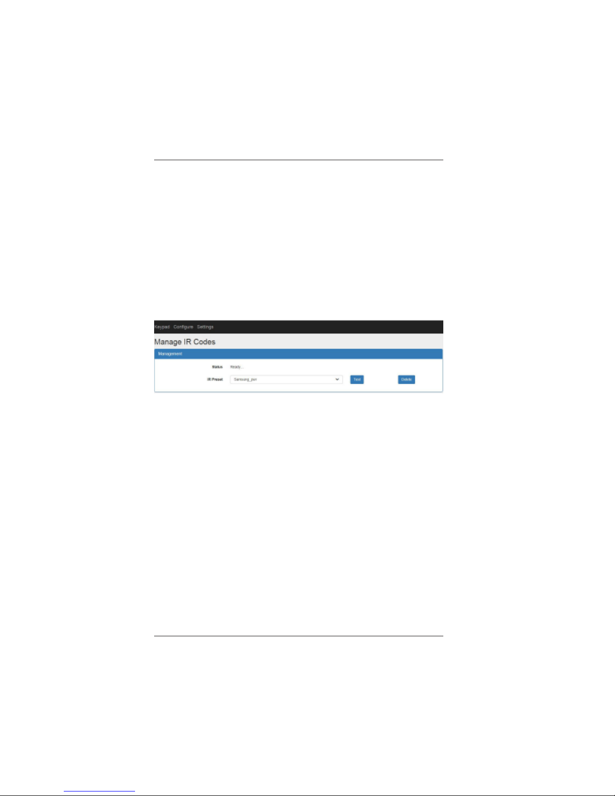
Configure IR Codes Management
The Configure IR Codes Management page is used to manage IR
codes in the ICP. Af ter an IR code is imported successfully, it will be
stored in memory and appear in the IR Preset drop down menu. T o test
an IR code, select the IR code from the IR Preset menu and click Test
button. Verify that the IR code works correctly on the target device. T o
delete an IR code from the IR Preset menu, select the desired IR code
and click the Delete button.
On the top menu click Configure and then click IR Codes
Management. The following page will be displayed:
Status: Indicates the status of the IR module.
IR Preset: Select from list of user imported IR codes.
Page 28
LBC-H/O-R-ICP User Manual
Link Bridge
TM
HBaseT/HDMI Receiver w/Inline Control Processor
Broadata Technical Support, [email protected]
29
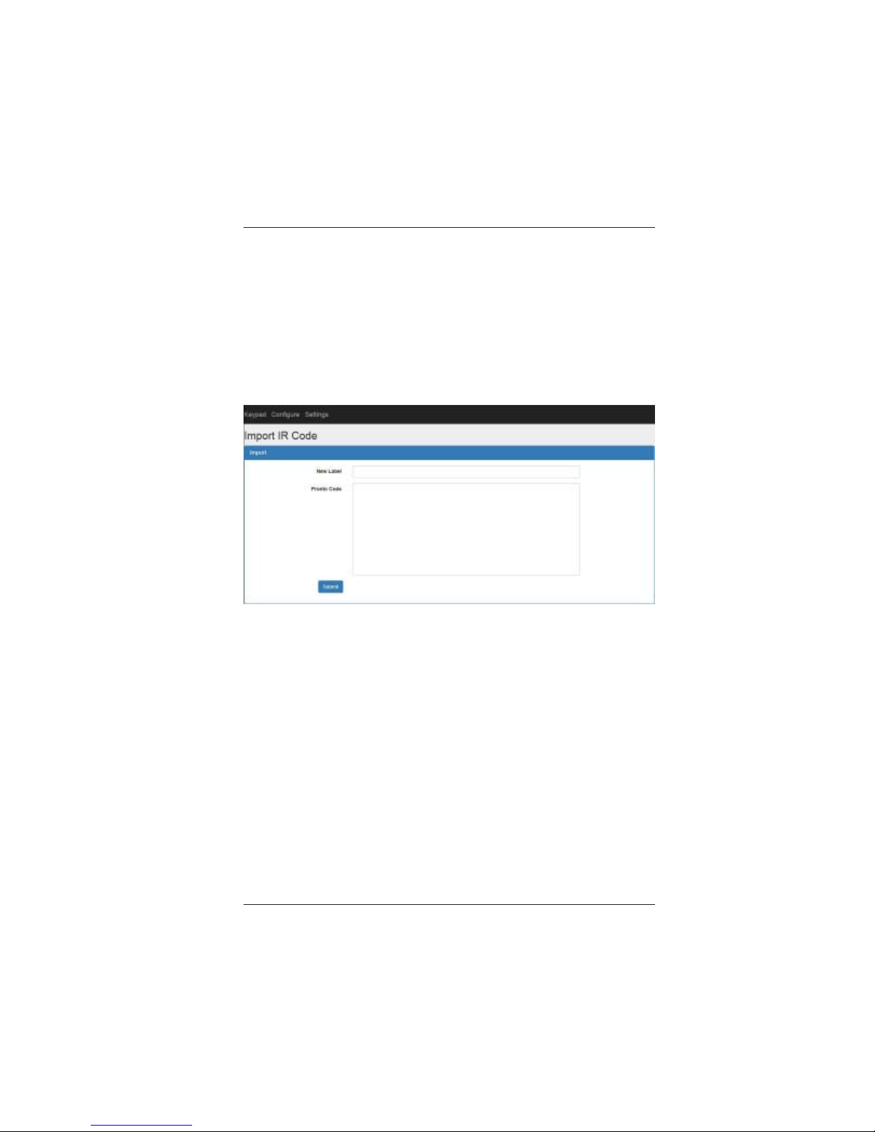
Configure IR Code Import
The Configure IR Code Import page is used to import an IR pronto
code. Once a code is imported, it will be stored in memory and is
available as an IR Preset. It can be tested in the Configure IR Code
page.
On the top menu click Configure and then click IR Code Import. The
following page will be displayed:
New Label: Enter a label for the IR code.
Pronto Code: Enter the pronto code to be imported.
Page 29
LBC-H/O-R-ICP User Manual
Link Bridge
TM
HBaseT/HDMI Receiver w/Inline Control Processor
Broadata Technical Support, (800) 214-0222
30
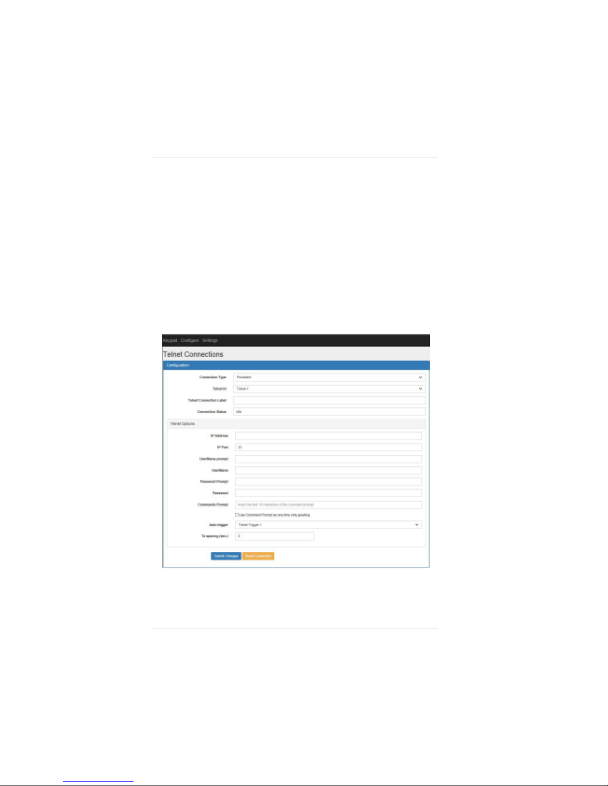
Configure T elnet Connections
The Configure T elnet Connections page is used to setup the telnet
connections for telnet key actions and auto actions. There are 2 telnet
connection types: Persistent and Action. The Persistent connection is
a permanent telnet connection between the ICP and the remote device.
This type of connection is typically used for monitoring telnet status
messages and triggering auto actions. Up to 2 Persistent connections
can be defined. The Action connection is a temporary telnet connection.
This type of connection is typically used for normal telnet actions. Up
to 8 Action connections can be defined.
On the top menu click Configure and then click T elnet Connections.
The following page will be displayed:
Connection Type: Select Persistent or Action.
T elnet ID: Select Telnet-1, 2 (Persistent type); Telnet-3, 4, 5, 6, 7, 8, 9,
10 (Action type).
Page 30

LBC-H/O-R-ICP User Manual
Link Bridge
TM
HBaseT/HDMI Receiver w/Inline Control Processor
Broadata Technical Support, [email protected]
31
T elnet Connection Label: Enter a label for the telnet connection.
Connection Status: This box shows the status of a persistent
connection.
Telnet Options
IP Address: Enter IP address of telnet server .
IP Port: Enter port number of telnet server . The default port number is
23.
UserName Prompt: Enter username prompt from telnet server. Leave
blank if there is no username prompt.
UserName: Enter user name required for log in. Leave blank if there is
no username.
Password Prompt: Enter password prompt from telnet server . Leave
blank if there is no password prompt.
Password: Enter password required for log in. Leave blank if there is
no password.
Command Prompt: Enter command prompt from telnet server. Only
the last 9 characters of the command prompt are needed. Leave blank
if there is no command prompt.
Note: Select check box below if string is used as a one-time only
greeting.
Auto Trigger: Select T elnet Trigger 1 or T elnet T rigger 2. This selection
associates the telnet connection with T elnet Trigger 1 or Telnet T rigger 2
used in Auto Actions.
Tx Spacing: Enter the delay (seconds) before command is transmitted
in Telnet Actions. Enter 0 if no delay is desired.
Page 31
LBC-H/O-R-ICP User Manual
Link Bridge
TM
HBaseT/HDMI Receiver w/Inline Control Processor
Broadata Technical Support, (800) 214-0222
32
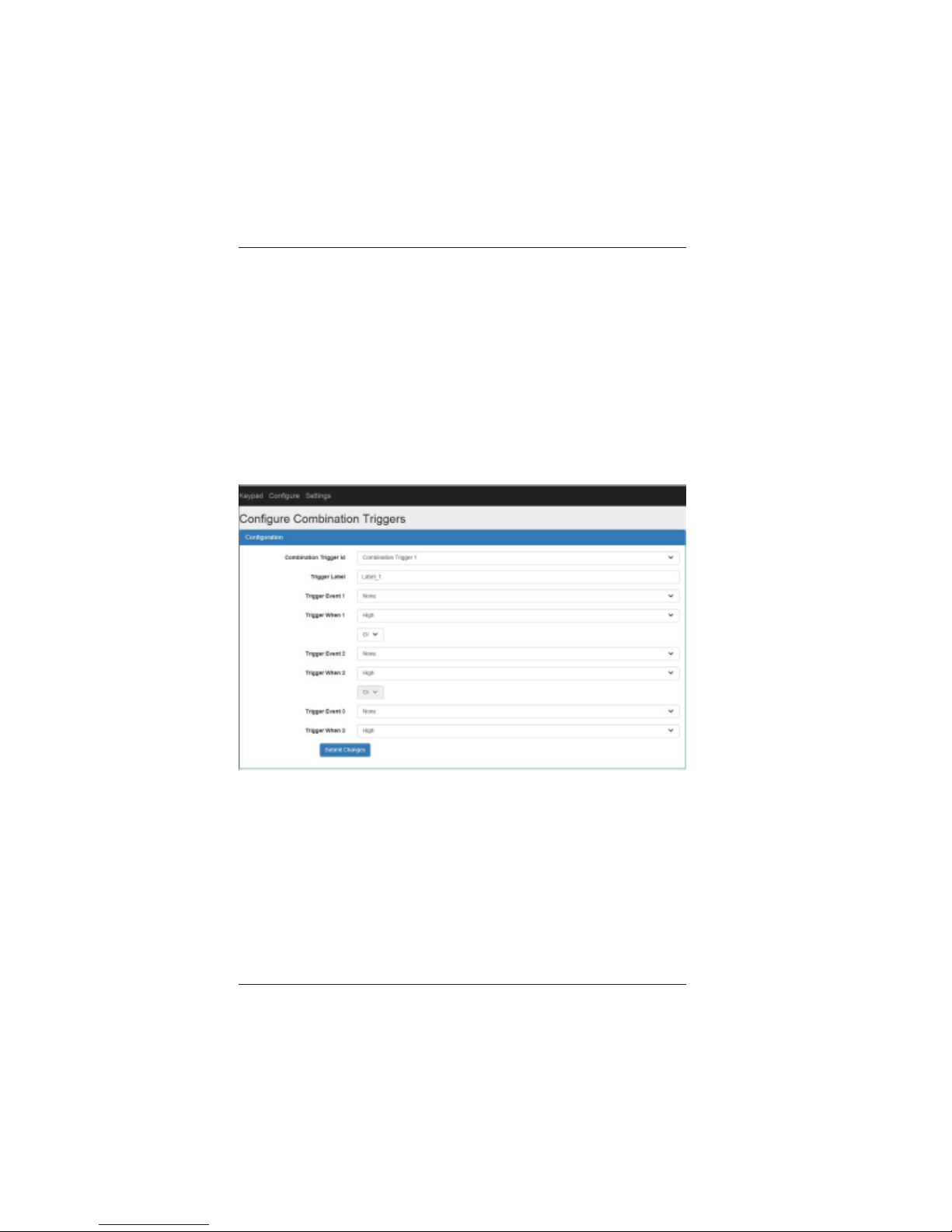
Configure Combination Triggers
The Configure Combination T riggers page is used to define up to 2
different combination triggers. Each combination trigger supports the
logical OR or AND function of up to 3 digit al input or video detect trigger
events. A combination trigger only supports a single logical function,
OR or AND. A combination trigger is Asserted when the trigger statement
evaluates to true. Once a combination trigger is defined, it will appear in
the Configure Auto Action T rigger menu.
On the top menu click Configure and then click Combination Triggers.
The following page will be displayed:
Combination Trigger ID: Select Combination T rigger 1 or 2.
Trigger Label: Enter name of combination trigger.
Trigger Event 1/2/3: Select the desired trigger from pull-down menu.
Trigger When 1/2/3: Select High or Low for digit al input triggers. Select
Asserted or De-asserted for video detect triggers.
OR/AND: Select the logical OR or AND function.
Page 32
LBC-H/O-R-ICP User Manual
Link Bridge
TM
HBaseT/HDMI Receiver w/Inline Control Processor
Broadata Technical Support, [email protected]
33
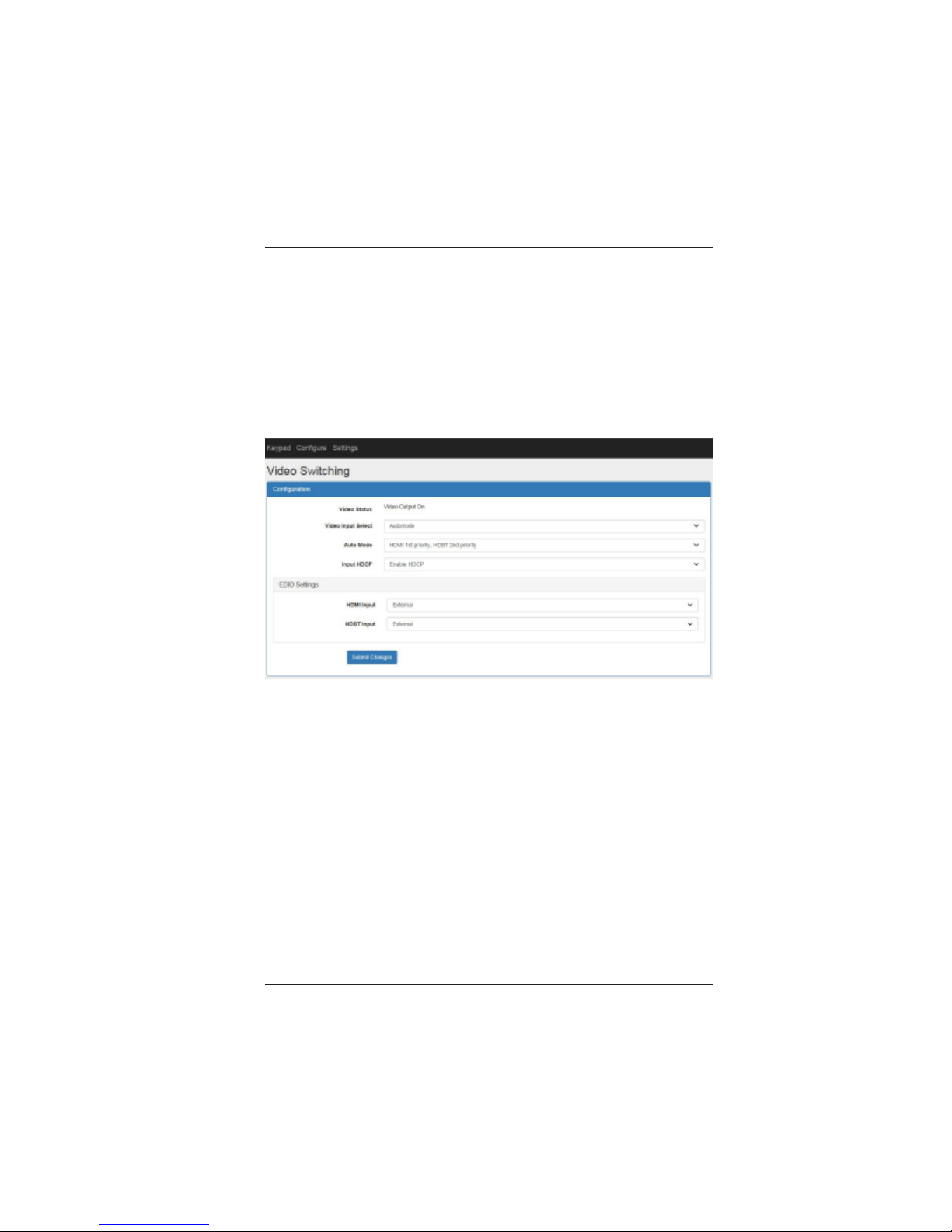
Configure Video Switching
The Configure Video Switching page is used to manually select the
video input. The video inputs can be automatically selected if Automode
is selected. HDCP and EDID management functions are also configured
on this page.
On the top menu click Configure and then click Video Switching.
The following page will be displayed:
Video status: Indicates the video output status.
Video Input Select: Select the video input to be displayed on the
HDMI output. Selecting Automode enables the auto video selection
logic. The auto selection logic will operate according to the mode
selected in the Auto Mode selection box.
Auto Mode: Select the desired auto mode.
Note: Not all auto modes below are available for all transmitters.
HDMI 1st priority , HDBT 2nd priority: The local HDMI port has priority.
If video is detected on the local HDMI port, this port will be automatically
selected to be displayed, regardless if video is plugged in at the
transmitter. If the video source is removed from the HDMI connector,
the output will automatically switch to the source connected at the
transmitter, if present.
Page 33

LBC-H/O-R-ICP User Manual
Link Bridge
TM
HBaseT/HDMI Receiver w/Inline Control Processor
Broadata Technical Support, (800) 214-0222
34
HDBT 1st priority , HDMI 2nd priority: The remote video port in the
transmitter has priority . If video is detected on the remote port, this port
will be automatically selected to be displayed, regardless if video is
plugged in at the receiver. If the video source is removed from the remote
port, the output will automatically switch to the source connected at the
local HDMI port, if present.
Last In First Out: The last video source plugged in will be selected and
displayed on the HDMI output.
If the current selected video source is removed, the last video source
plugged in will be selected.
Input HDCP: Select Enable HDCP or Disable HDCP.
EDID Settings - HDMI Input: Select the desired EDID for the local
HDMI input from the drop down menu.
EDID Settings - HDBT Input: Select the desired EDID for the HDBT
input port from the drop down menu. The selected EDID will pass through
to the remote transmitter.
Page 34
LBC-H/O-R-ICP User Manual
Link Bridge
TM
HBaseT/HDMI Receiver w/Inline Control Processor
Broadata Technical Support, [email protected]
35
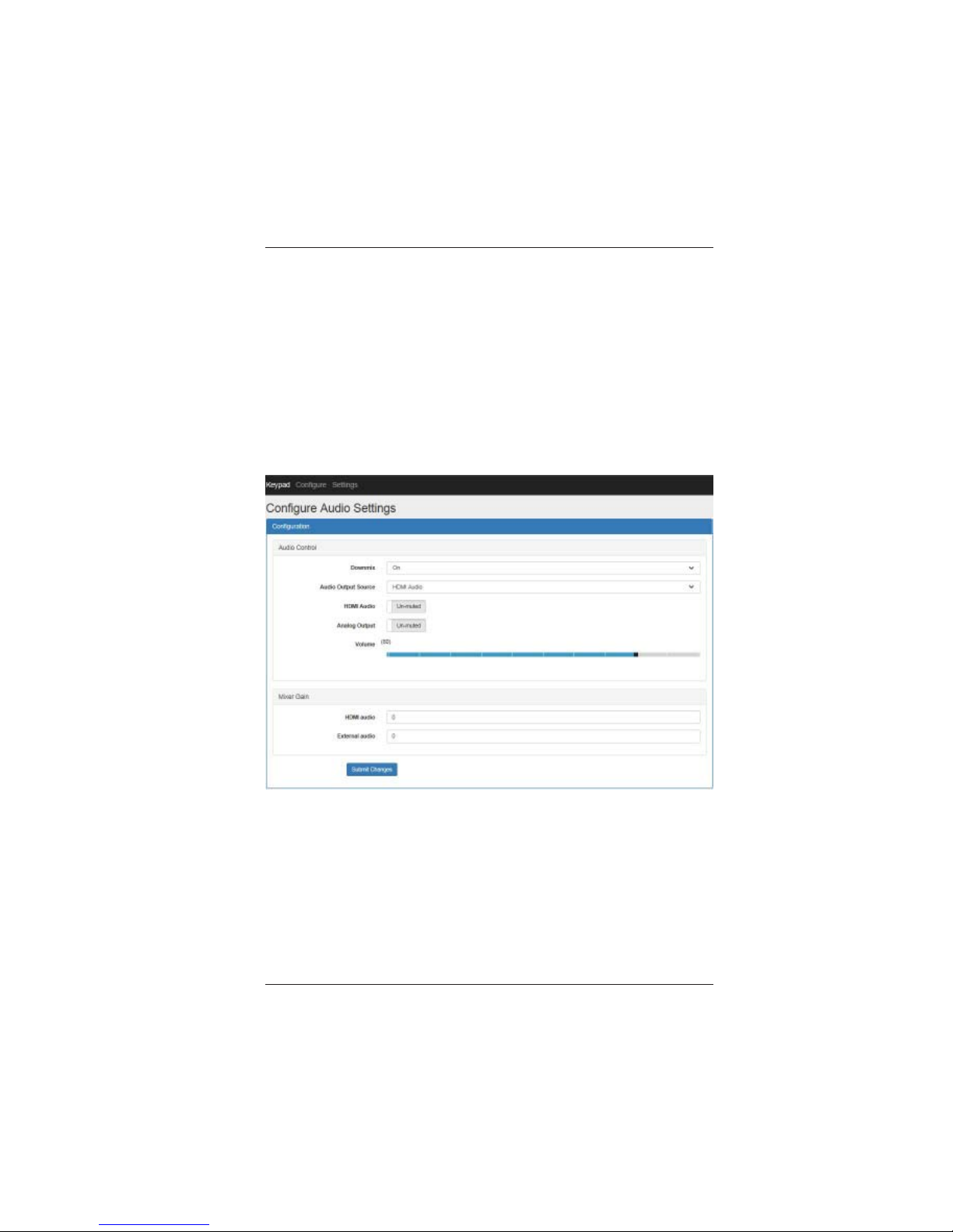
Configure Audio Settings
The Configure Audio Settings page is used for configuring the audio
settings of the analog audio output available in Terminal Block A. The
analog audio output source selection, down mix, volume, muting and
mixer functions are controlled on this page. The mixer function “mixes”
the de-embedded HDMI audio and the external analog audio input at
different gain levels.
On the top menu click Configure and then click Audio Settings. The
following page will be displayed:
Downmix: Select On to enable the down mix feature. Multi-channel
HDMI audio will be down mixed to 2-channel stereo before outputting to
the analog audio output.
Note: Down mix is enabled by default. Only multi-channel PCM audio
can be down mixed. Multi-channel audio such as Dolby Digital or DTS
cannot be decoded.
Audio Output Source: Select the audio source for the analog audio
output. The sources are the de-embedded HDMI audio, the external
analog audio input or the mixer output.
Page 35

LBC-H/O-R-ICP User Manual
Link Bridge
TM
HBaseT/HDMI Receiver w/Inline Control Processor
Broadata Technical Support, (800) 214-0222
36
HDMI Audio: Select Mute or Unmute to mute or unmute the HDMI
audio.
Analog Output: Select Mute or Unmute to mute or unmute the analog
audio output.
V olume: Drag the slider left or right to decrease or increase the analog
audio output volume.
Mixer Gain - HDMI audio: Set the gain level for the de-embedded
HDMI audio input to the mixer. The gain range is 0 to 15 dB.
Mixer Gain - External audio: Set the gain level for the external analog
audio input to the mixer. The gain range is 0 to 15 dB.
Page 36
LBC-H/O-R-ICP User Manual
Link Bridge
TM
HBaseT/HDMI Receiver w/Inline Control Processor
Broadata Technical Support, [email protected]
37
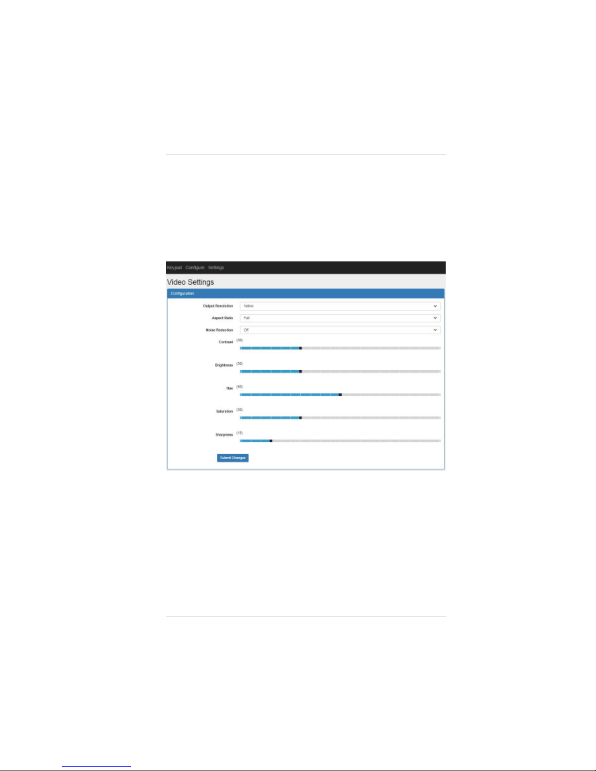
Configure Video Settings
The Configure Video Settings page is only available on the LBC-H/O-
R-ICP-SCL model. This page is used to configure the various video
settings of the scaler.
On the top menu click Configure and then click Video Settings. The
following page will be displayed:
Output Resolution: Select the output resolution from the drop down
menu. See Appendix x for list of supported output resolutions.
Aspect Ratio: Select the output aspect ratio from the drop down menu.
Noise Reduction: Select the level of noise reduction.
Contrast: Drag the slider left or right to decrease or increase the Contrast
level.
Brightness: Drag the slider left or right to decrease or increase the
Brightness level.
Page 37
LBC-H/O-R-ICP User Manual
Link Bridge
TM
HBaseT/HDMI Receiver w/Inline Control Processor
Broadata Technical Support, (800) 214-0222
38
Hue: Drag the slider left or right to decrease or increase the Hue level.
Saturation: Drag the slider left or right to decrease or increase the
Saturation level.
Sharpness: Drag the slider left or right to decrease or increase the
Sharpness level.
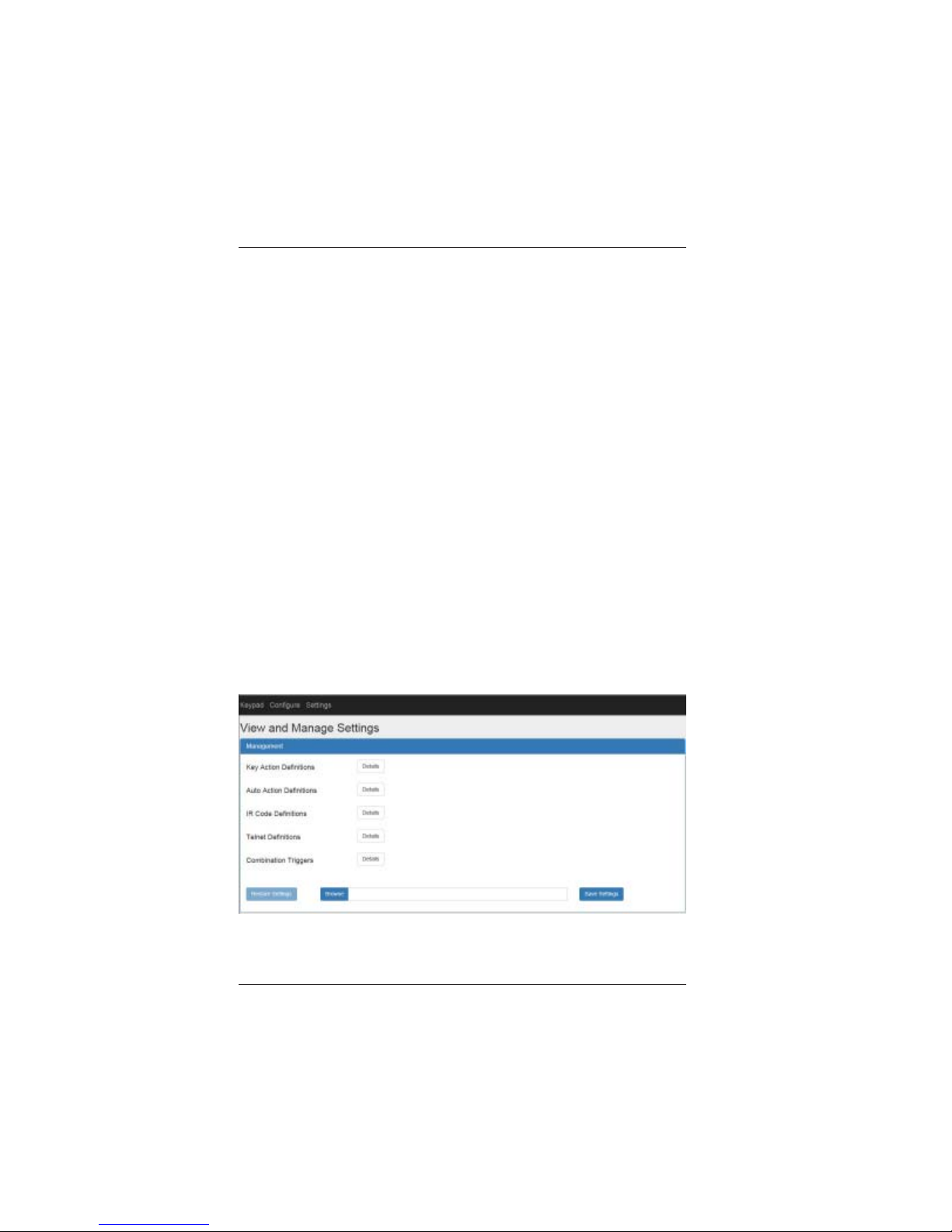
View and Manage Settings
The View and Manage Settings page shows the current settings of
the Key Action Definitions, Auto Action Definitions, IR Code
Definitions, Telnet Definitions and Combination Triggers. Click
the Details button next to the associated Definitions to display the
settings details. ICP settings are saved to a file on the local PC using
the Save Settings button. ICP settings are restored from a file using
the Restore Settings button.
On the top menu click Settings and then click View and Manage
Settings. The following page will be displayed:
Page 38
LBC-H/O-R-ICP User Manual
Link Bridge
TM
HBaseT/HDMI Receiver w/Inline Control Processor
Broadata Technical Support, [email protected]
39
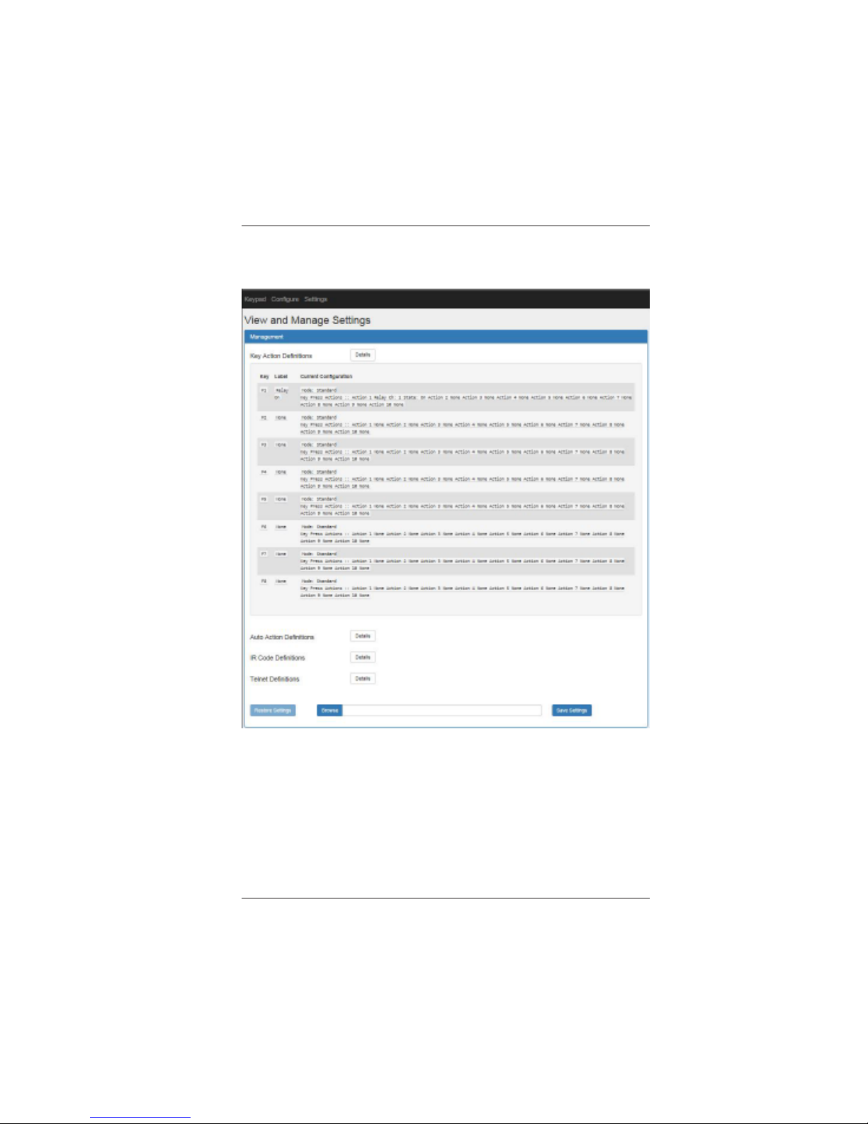
Click the Key Action Definitions Details button and the following will
be displayed:
Page 39
LBC-H/O-R-ICP User Manual
Link Bridge
TM
HBaseT/HDMI Receiver w/Inline Control Processor
Broadata Technical Support, (800) 214-0222
40
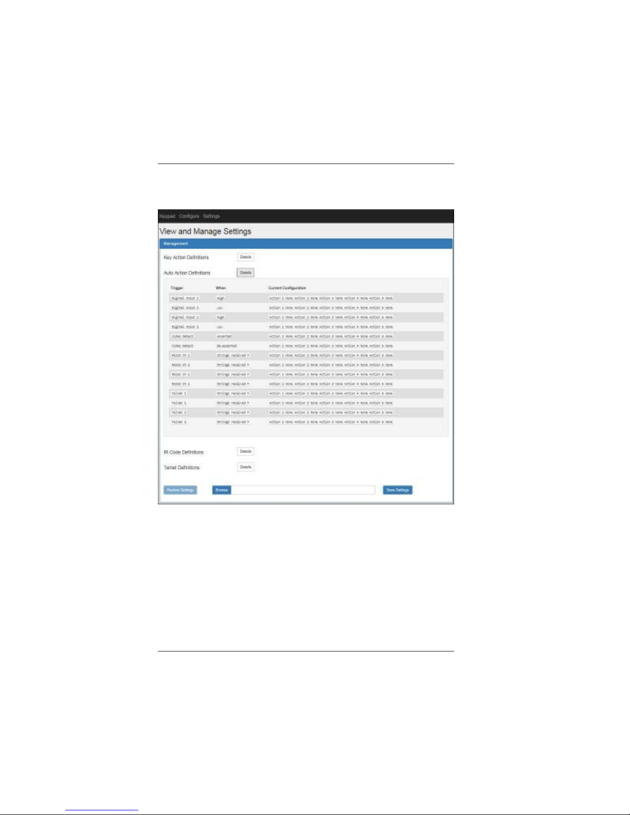
Click the Auto Action Definitions Details button and the following will
be displayed:
Page 40
LBC-H/O-R-ICP User Manual
Link Bridge
TM
HBaseT/HDMI Receiver w/Inline Control Processor
Broadata Technical Support, [email protected]
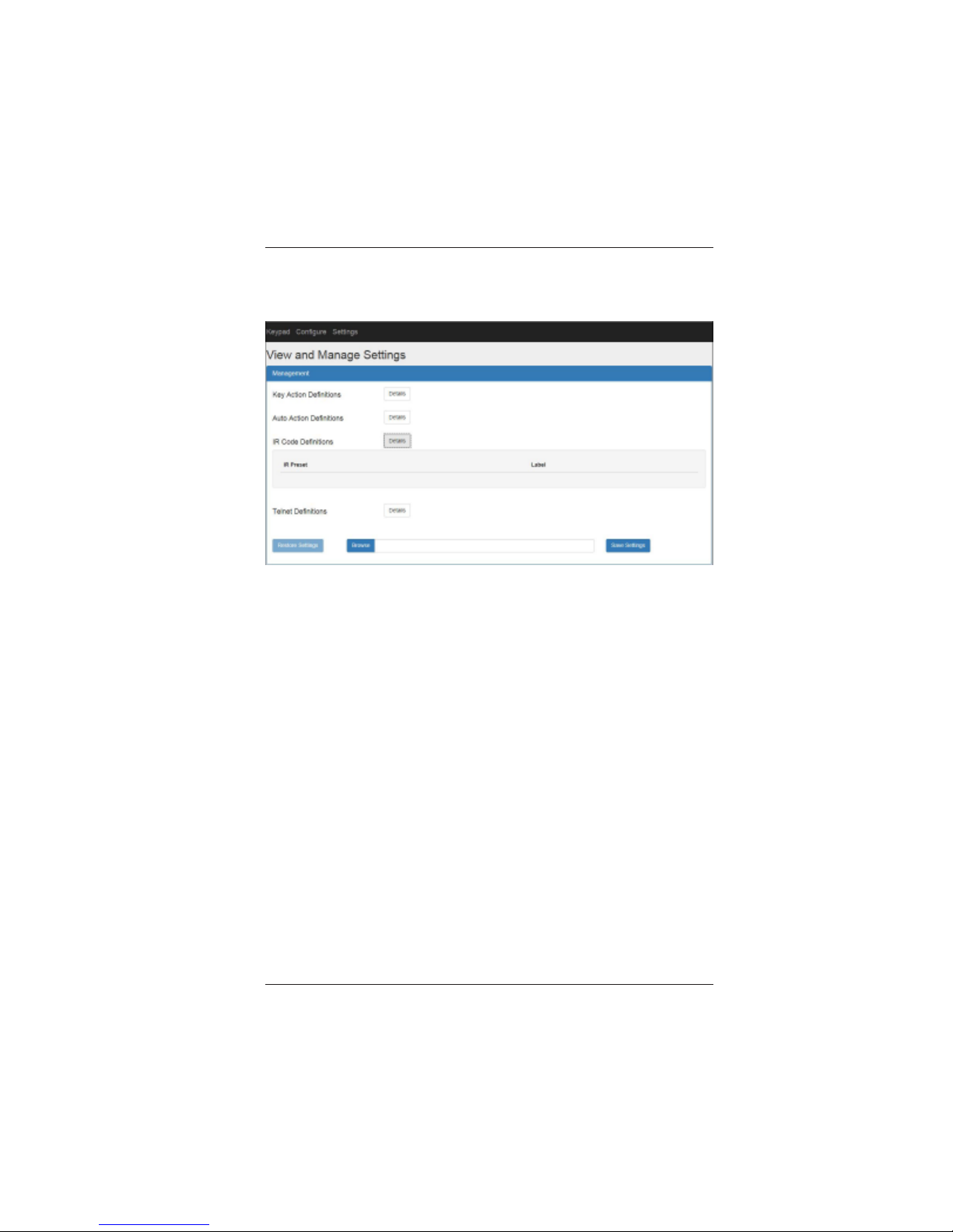
41
Click the IR Code Definitions Details button and the following will be
displayed:
Page 41
LBC-H/O-R-ICP User Manual
Link Bridge
TM
HBaseT/HDMI Receiver w/Inline Control Processor
Broadata Technical Support, (800) 214-0222
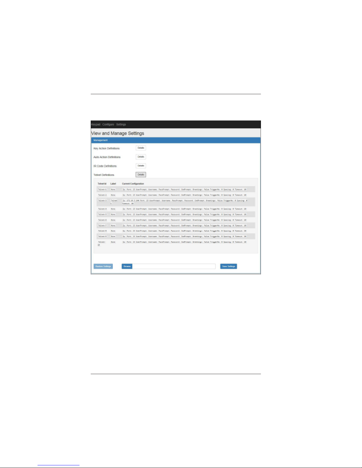
42
Click the Telnet Definitions Details button and the following will be
displayed:
Page 42
LBC-H/O-R-ICP User Manual
Link Bridge
TM
HBaseT/HDMI Receiver w/Inline Control Processor
Broadata Technical Support, [email protected]
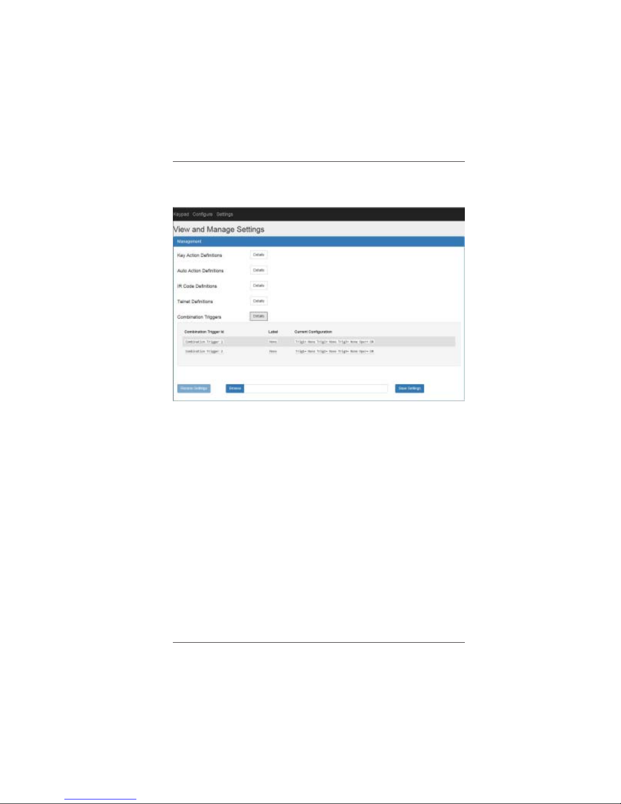
43
Click the Combination Triggers Det ails button and the following will
be displayed:
Page 43
LBC-H/O-R-ICP User Manual
Link Bridge
TM
HBaseT/HDMI Receiver w/Inline Control Processor
Broadata Technical Support, (800) 214-0222
44
Examples
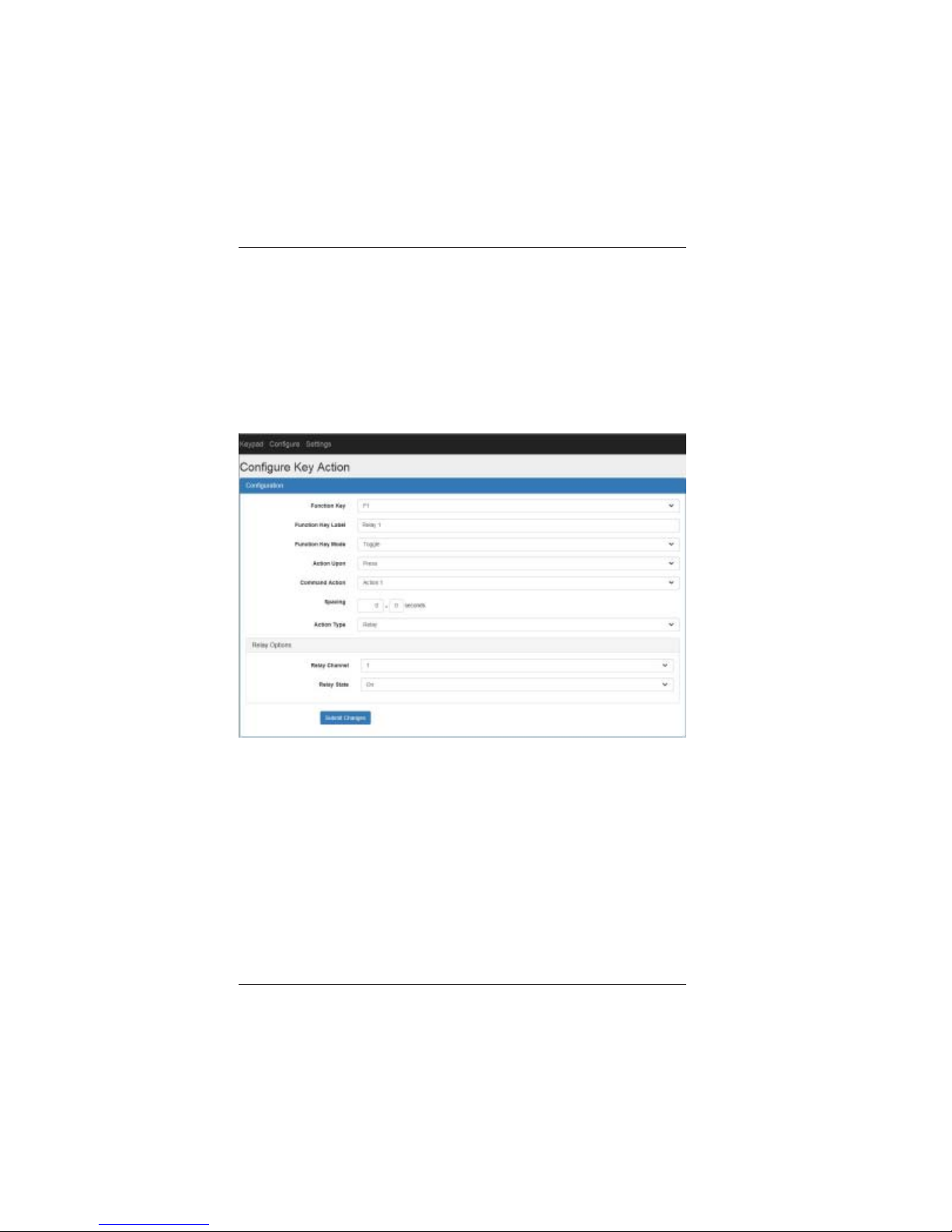
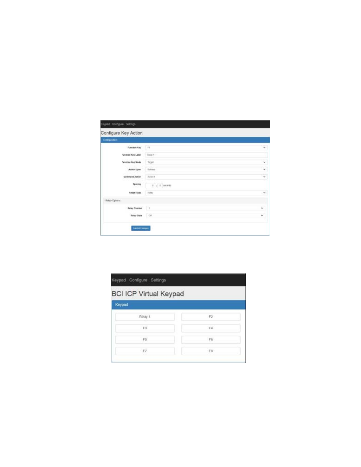
Example #1: This example configures the F1 key on the virtual keypad
as a toggle key to turn on/off Relay channel 1.
On the top menu click Configure and then Key Action.
Configure F1 Key toggle-press action, to turn Relay channel 1 On as
follows:
Click Submit Changes.
Page 44
LBC-H/O-R-ICP User Manual
Link Bridge
TM
HBaseT/HDMI Receiver w/Inline Control Processor
Broadata Technical Support, [email protected]
45
Configure F1 Key toggle-release action, to turn Relay channel 1 Off as
follows:
Click Submit Changes.
On the top menu click Keypad. The following virtual keypad should be
displayed:
Page 45

LBC-H/O-R-ICP User Manual
Link Bridge
TM
HBaseT/HDMI Receiver w/Inline Control Processor
Broadata Technical Support, (800) 214-0222
46
5.0 SPECIFICATIONS
VIDEO OUTPUT (TRANSMISSION)
HDMI Up to 1080p @ 60Hz or
1920 x 1200 @ 60Hz or 4K@30Hz
Connector HDMI Female Plug
Protocol DDC/EDID/HDCP Capable
AUDIO INPUT/OUTPUT (TRANSMISSION)
Signal Format L/R Analog
Audio Output Connector T erminal Block
RS-232 (TRANSMISSION)
Data Rate Up to 57.6kbaud
Connector Terminal Block
IR (TRANSMISSION)
Data Rate 30-60KHz
Connector Terminal Block
HDBT (TRANSMISSION)
Cable Type CA T-5e/6 or higher
Number of Cables 1
Connector/Distance RJ-45/Up to 100m
ETHERNET (CONTROL)
Channel Capacity 2
Connector Female RJ-45 (integrated Activity and
Link LEDs)
Data Rate 10/100Base-T, half/full duplex with
autodetect
Protocols DHCP , HTTP, TCP/IP, UDP/IP,
AUTOIP , Telnet
Page 46

LBC-H/O-R-ICP User Manual
Link Bridge
TM
HBaseT/HDMI Receiver w/Inline Control Processor
Broadata Technical Support, [email protected]
47
RS-232 (CONTROL)
Channel Capacity 3 (no flow control) or 2 (with RTS/
CTS flow control)
Baud Rate 2400 to 115200 baud
Connector Terminal block
DIGIT AL I/O (CONTROL)
Channel Capacity 2 digital input/output (configurable)
Digital Input Input voltage range: 0 to 24VDC
Threshold low to high: 2 VDC
Threshold high to low: 0.8 VDC
Digital Output Output voltage high: 3 VDC min
Output voltage low: 0.55 VDC max
(64 mA sink max)
Connector Terminal block
IR (CONTROL)
Channel Capacity 1 out
Connector Terminal Block
Carrier Frequency 30 kHz to 60 kHz (Output)
RELA Y (CONTROL)
Channel Capacity 2 normally open
relays
Relay Contact Rating 24 VDC, 1A
Connector Terminal block
PHYSICAL
Dimensions 8.36” (D) x 4.23” (W) x 1.12” (H)
Power Consum ption 24 VDC @ 1.25A
Operating T emperature 0 to 40-deg C
Humidity 0 to 95%, non-condensing
Page 47

LBC-H/O-R-ICP User Manual
Link Bridge
TM
HBaseT/HDMI Receiver w/Inline Control Processor
Broadata Technical Support, (800) 214-0222
48
6.0 SERVICE PROCEDURE
6.1 Replacement Policy
Standard products found defective on arrival (DOA) will be
replaced, based on availability , within 24 to 48 hours anywhere
in the U.S. Please call Customer Service at 800-214-0222 for
information.
6.2 Return/Repair Service
The Link Bridge LBC-H/O-R-ICP System contains no user
serviceable components. If you have a problem with your unit,
please contact the Customer Service Department. To facilitate
our return/repair processing please contact Broadata
Communications, Inc. to obtain a Return Material Authorization
(RMA). Please include the following information:
• Product model number
• Serial Number
• Complete description of problem
• Hardware installation description
Broadata Communications, Inc.
2545 West 237th Street, Suite K
T orrance, CA 90505
1-800-214-0222
(310) 530-1416
(310) 530-5958 (Facsimile)
e-mail: [email protected]
Website: www .broadatacom.com
Page 48

LBC-H/O-R-ICP User Manual
Link Bridge
TM
HBaseT/HDMI Receiver w/Inline Control Processor
Broadata Technical Support, [email protected]
49
7.0 LIMITED W ARRANTY
Broadata Communications, Inc. (BCI) warrants, for a period of one
year from date of shipment, each product sold shall be free from defects
in material and workmanship. BCI will correct, either by repair, or at
BCI’s election, by replacement, any said products that in our sole
discretion prove to be defective and are returned to the manufacturing
location within 30 days after such defect is ascertained. All warranties
are limited to defects arising under normal use and do not include
malfunctions or failure resulting from misuse, abuse, neglect, alterations,
electrical power problems, usage not in accordance with product
instructions, improper installation, or damage determined by BCI to
have been caused by the Buyer or repair made by a third party . Limited
warranties granted on products are to the initial customer end-user and
are not transferable. OUR LIABILITY UNDER THIS W ARRANTY SHALL
IN ANY CASE BE LIMITED TO THE INVOICE VALUE OF THE
PRODUCT SOLD AND BCI SHALL NOT BE LIABLE TO ANYONE FOR
CONSEQUENTIAL OR INCIDENT AL DAMAGES ARISING FROM THE
USE OF ITS PRODUCTS OR THE SALE THEREOF. We make NO
WARRANTY AS TO THE MERCHANTABILITY OF ANY GOODS, OR
THAT THEY ARE FIT FOR ANY PARTICULAR PURPOSE OR END
APPLICA TION NOR DO WE MAKE ANY WARRANTY, EXPRESSED
OR IMPLIED OTHER THAN AS STATED ABOVE.
Page 49

LBC-H/O-R-ICP User Manual
Link Bridge
TM
HBaseT/HDMI Receiver w/Inline Control Processor
Broadata Technical Support, (800) 214-0222
50
Page 50

LBC-H/O-R-ICP User Manual
Link Bridge
TM
HBaseT/HDMI Receiver w/Inline Control Processor
Broadata Technical Support, [email protected]
51
Page 51

Broadata Communications, Inc.
2545 West 237th Street, Suite K
T orrance, CA 90505
1-800-214-0222
(310) 530-1416
(310) 530-5958 (Facsimile)
e-mail: [email protected]
Website: www .broadatacom.com
60000-LBCHORICPv3.0
 Loading...