

Page 1

730E-R-ID
INDOOR FIBER OPTIC
CA TV RECEIVER
BCI reserves the right to make changes to the products described herein without
prior notice or consent. No liability is assumed as a result of their use or
application. All rights reserved.
©2008 Broadata Communications, Inc.
Page 2
BCI 730E User’s Manual
Indoor Fiber Optic CATV Receiver
Broadata Technical Support, [email protected]
3
SAFETY INSTRUCTIONS AND
COMPLIANCE DECLARATIONS
PLEASE OBSERVE THE FOLLOWING SAFETY
PRECAUTIONS AS OUR PRODUCTS CONT AIN
CLASS I LASER PRODUCTS
WARNING
Do not disconnect the fiber optic connector while the unit is powered
up. Exposure to laser radiation is possible when the laser fiber optic
connector is disconnected while the unit is powered up.
Although the fiber optic connectors in this product emit only Class 1
energy that is below the levels considered to be hazardous, one should
never stare directly into a fiber optic connector or an unconnected fiber
end unless one can be certain that no exposure to laser energy could
occur.
CAUTION
This manual is intended for use by trained service personnel. The use
of controls, making adjustments, or performing operations other than
those specified may result in hazardous radiation exposure.
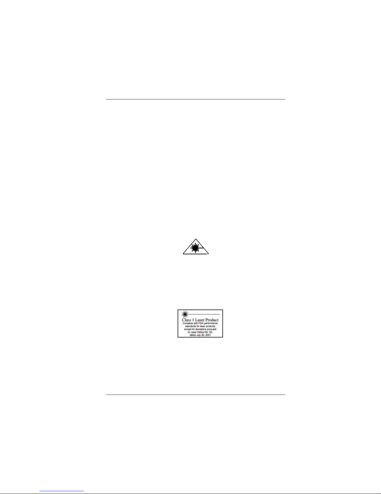
The following label or equivalent is located on the surface of laser products.
This label indicates that the product is classified as a CLASS 1 LASER
PRODUCT.
SURGE PROTECTION DEVICE RECOMMENDED
This product contains sensitive electrical components that may be
damaged by electrical spikes, surges, electric shock, lightning strikes,
etc. Use of surge protection systems is highly recommended in order
to protect and extend the life of your equipment.
Page 3

BCI 730E User’s Manual
Indoor Fiber Optic CATV Receiver
Broadata Technical Support, (800) 214-0222
4
TABLE OF CONTENTS
1.0 PRODUCT DESCRIPTION ..........................................5
2.0 BLOCK DIAGRAM ........................................................ 6
3.0 SPECIFICATIONS .........................................................7
4.0 INSTALLATION & ADJUSTMENTS ............................. 9
5.0 SERVICE PROCEDURE .............................................10
5.1 REPLACEMENT POLICY ...........................................10
5.2 RETURN AND REPAIR SERVICE ..............................10
6.0 LIMITED WARRANTY .................................................11
Page 4

BCI 730E User’s Manual
Indoor Fiber Optic CATV Receiver
Broadata Technical Support, [email protected]
5
1.0 PRODUCT DESCRIPTION
730E-R-ID is a stand alone AM optical receiver which may be mounted
in a 19" rack. Located at either a headend or a remote site, the unit is a
versatile, cost effective alternative to devices with bulkier environmentally
sealed and ruggedized housings.
Once the low distortion, low noise receiving module recovers the RF
signals from the 1310 or 1550 optical carrier, they are amplified and
delivered to the receiver’s RF output. LED on the receiver’s front panel
indicate the presence of optical power. If the input optical power is above
-8dBm, the light is lit green; otherwise, it is lit red. Meanwhile on the
front panel, there is also digital display of input optical power displayed
in mW.
Figure 1-1
730E-R-ID Front Panel
Optical Power
< -8dBm
Fiber Optic Receiver
Page 5
BCI 730E User’s Manual
Indoor Fiber Optic CATV Receiver
Broadata Technical Support, (800) 214-0222
6
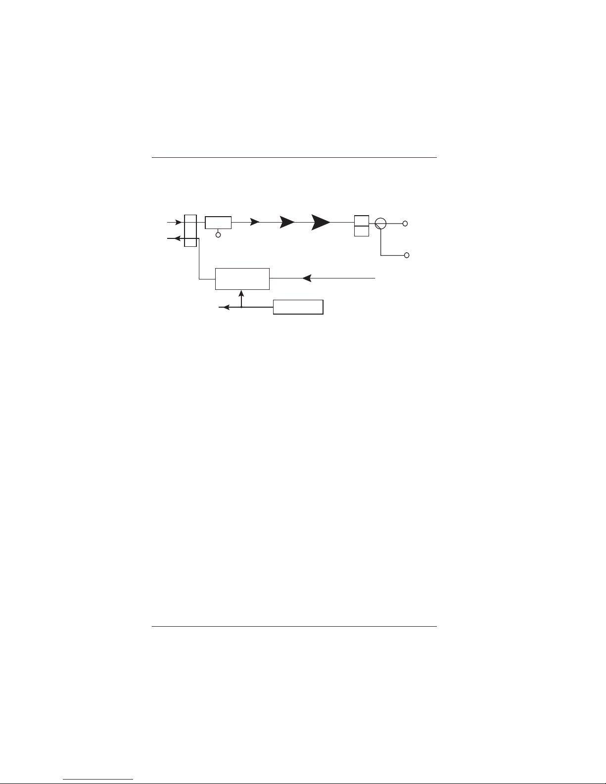
2.0 BLOCK DIAGRAM
Figure 2-1
730E-R-ID Block Diagram
Optical
Receive
Optical Return
Transmitter
Power Supply
IN
OUT
Fiber
H
L
A1
A2 A3
A4
+24V
FLT
Digital Display
SP
Port 1#
Port 2#
Page 6

BCI 730E User’s Manual
Indoor Fiber Optic CATV Receiver
Broadata Technical Support, [email protected]
7
3.0 SPECIFICATIONS
Forward Path, Optical
Optical Input Range -8dBm to +2dBm, 0dBm nominal
Optical Wavelength 1290nm to 1600nm
Optical Return Loss >45dB
Fiber Connector SC/APC, FC/APC
Return Path, Optical (optional)
Optical Output Power Choice of 1mW or 2mW
Optical Wavelength 1310nm ±10nm
Optical Power -5dBm to +2dBm
Fiber Connector SC/APC, FC/APC
Forward Path, RF
Bandwidth 45MHz to 750MHz/ 862MHz
Output Level (@ 0dBm) 104±1dBµV
RF impedance 75Ω
Flatness ±0.75dB
Distortions CTB> -65dBc @ -1dBm optical input
CSO> -60dBc @ -1dBm optical input
C/N >52 PAL @ -1dBm optical input
(Carrier Loading 77 NTSC / 59 PAL
Channels to 550MHz)
Output Return Loss >16dB
T est point -12dB
Return Path, RF (optional)
Bandwidth 5 - 200MHz
RF input power 80dBµV
Flatness ±1dB
Return Loss >14dB
General
Power 220VAC/110V AC
RF Connector F
Dimensions (W x D x H) 18.98” x 9.25” x 1.73”
Operating T emperature 0ºC to +50ºC
Page 7

BCI 730E User’s Manual
Indoor Fiber Optic CATV Receiver
Broadata Technical Support, (800) 214-0222
8
IMPORTANT
1. Please do not attempt to look into the optical connector with
power applied, eye damage may result.
2. It is prohibited to touch the laser without any anti-static tool.
3. The optical input power should be only from -6 to +2dBm. The
receiver may work when input power is lower than -6dBm,
but CNR will be largely deteriorated; when the input power is
higher than 2dBm, CTB and CSO will be deteriorated and may
even cause the damage of the optical receiving module.
4. Clean the end of the connector with a lint free tissue moistened
with alcohol before you insert the connector into the receptacle
of the SC/APC adapter.
5. This machine should be grounded before operation. The
grounded resistence should be <4
Ω.Ω.
Ω.Ω.
Ω.
6. Please carefully bend the fiber.
Page 8

BCI 730E User’s Manual
Indoor Fiber Optic CATV Receiver
Broadata Technical Support, [email protected]
9
4.0 INSTALLATION AND ADJUSTMENT
1. Power Connection
Under normal circumstances, after the power is connected. S tatus
light lits red.
2. Fiber Connection
Cut off the power and take down the bolt in Fiber Input Port then
perform the following steps:
• Carefully remove the protective cap from the SC/APC connector.
• Clean the end of the connector with a lint free tissue moistened
with alcohol.
• Insert the connector into the receptacle of the SC/APC adapter.
• Power on, the status light in front panel lits green when the input
power is above -8dBm. Otherwise, it is lit red.
3. T est point
On the rear panel there is one -12dB test point.
4. Cable Connection
Connect the cables accordingly .
Important: all the input or output ports (not including the test
ports) not in use should be connected to 75
ΩΩ
ΩΩ
Ω resistance.
5. Optical Power Monitoring
When front panel LED status light is red, it indicates that the input
optical power is lower than –8dBm. In this case, you should check
the optical link, the SC/APC connector and the output optical power
of the transmitter.
Page 9

BCI 730E User’s Manual
Indoor Fiber Optic CATV Receiver
Broadata Technical Support, (800) 214-0222
10
5.0 SERVICE PROCEDURE
5.1 Replacement Policy
Standard products found defective on arrival (DOA) will be
replaced, based on availability . Please call Customer Service
at 800-214-0222 for information.
5.2 Return/Repair Service
The 730E System contains no user serviceable components. If
you have a problem with your unit, please contact the Customer
Service Department. To facilitate our return/repair processing
please contact Broadata Communications, Inc. to obtain a
Return Material Authorization (RMA). Please include the
following information:
• Product model number
• Serial Number
• Complete description of problem
• Hardware installation description
Broadata Communications, Inc.
2545 West 237th Street, Suite K
T orrance, CA 90505
1-800-214-0222
(310) 530-1416
(310) 530-5958 (Facsimile)
e-mail: [email protected]
Website: www .broadatacom.com
Page 10

BCI 730E User’s Manual
Indoor Fiber Optic CATV Receiver
Broadata Technical Support, [email protected]
11
6.0 LIMITED W ARRANTY
Broadata Communications, Inc. (BCI) warrants, for a period of one year
from date of shipment, each product sold shall be free from defects in
material and workmanship. BCI will correct, either by repair, or at BCI’ s
election, by replacement, any said products that in our sole discretion
prove to be defective and are returned to the manufacturing location
within 30 days after such defect is ascertained. All warranties are limited
to defects arising under normal use and do not include malfunctions or
failure resulting from misuse, abuse, neglect, alterations, electrical power
problems, usage not in accordance with product instructions, improper
installation, or damage determined by BCI to have been caused by the
Buyer or repair made by a third party. Limited warranties granted on
products are to the initial customer end-user and are not transferable.
OUR LIABILITY UNDER THIS W ARRANTY SHALL IN ANY CASE BE
LIMITED TO THE INVOICE VALUE OF THE PRODUCT SOLD AND BCI
SHALL NOT BE LIABLE TO ANYONE FOR CONSEQUENTIAL OR
INCIDENT AL DAMAGES ARISING FROM THE USE OF ITS PRODUCTS
OR THE SALE THEREOF. We make NO WARRANTY AS TO THE
MERCHANT ABILITY OF ANY GOODS, OR THA T THEY ARE FIT FOR
ANY P ARTICULAR PURPOSE OR END APPLICATION NOR DO WE
MAKE ANY WARRANTY, EXPRESSED OR IMPLIED OTHER THAN
AS ST A TED ABOVE.
Page 11

Broadata Communications, Inc.
2545 West 237th Street, Suite K
T orrance, CA 90505
1-800-214-0222
(310) 530-1416
(310) 530-5958 (Facsimile)
e-mail: [email protected]
Website: www .broadatacom.com
60000-730E
 Loading...