

Brizo VETTIS T66T088 Installation Instructions Manual
1
91844 Rev. A
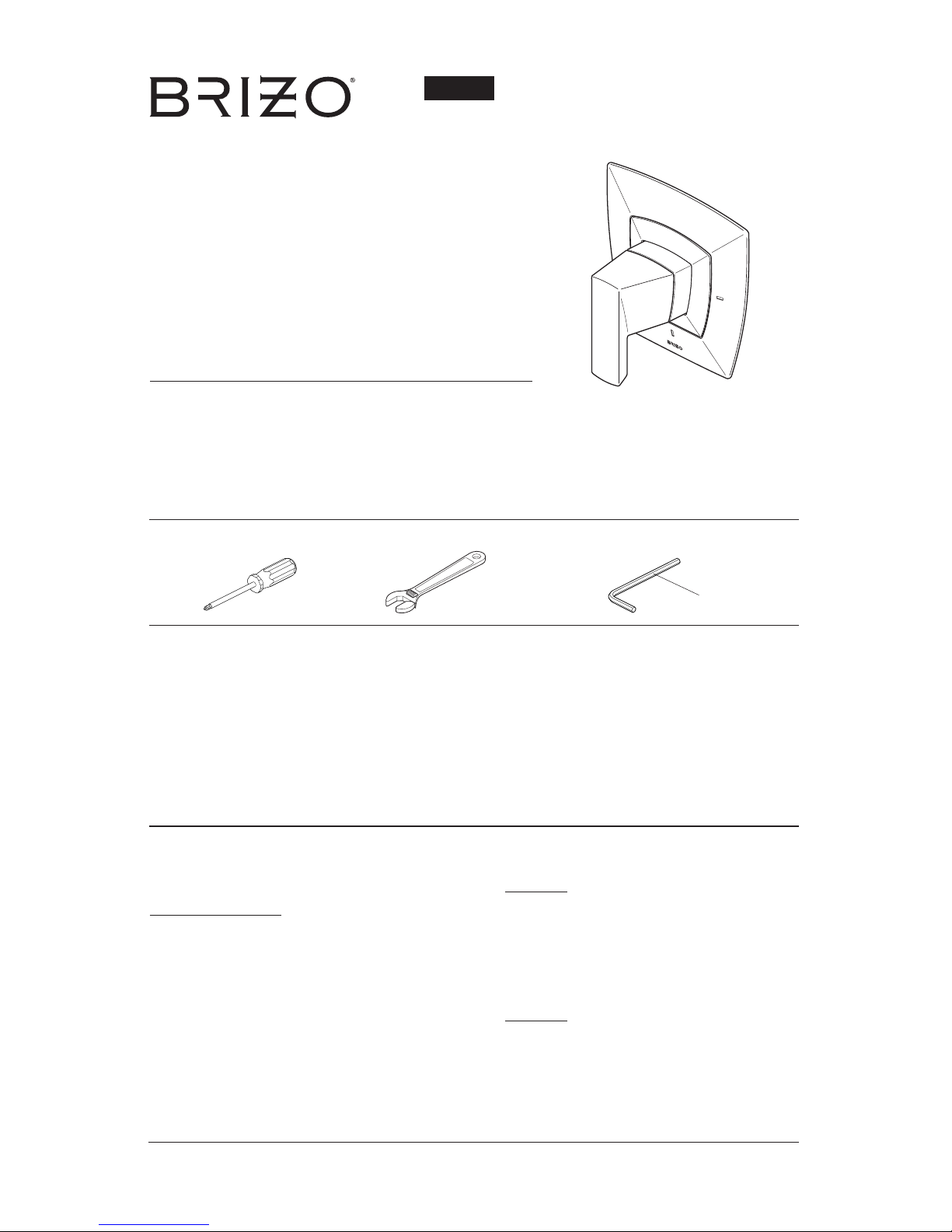
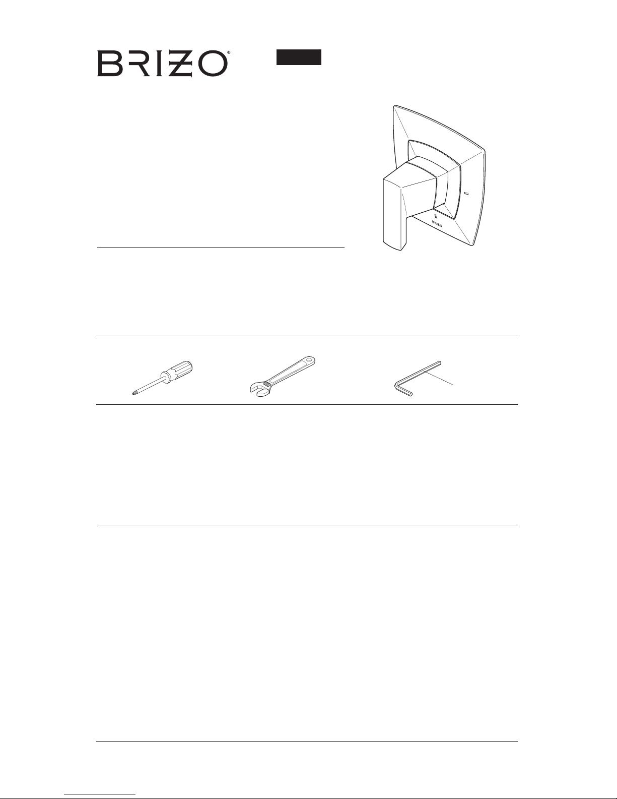
Models
T66T088▲
Series
VETTIS
™
SENSORI® THERMOSTATIC
VALVE TRIM
CAUTION: This system/device must be set by the installer
to ensure safe, maximum temperature. Any change in the
setting may raise the discharge temperature above the limit
considered safe and may lead to hot water burns.
NOTICE TO INSTALLER: CAUTION!–As the installer
of this valve, it is your responsibility to properly
INSTALL and ADJUST this valve per the instructions
given. This valve does not automatically adjust for
inlet temperature changes, therefore, someone must
make the necessary temperature knob adjustments
at the time of installation and further adjustments
may be necessary due to seasonal water temperature
change. YOU MUST inform the owner/user of this
requirement by following the instructions. If you or
the owner/user are unsure how to properly make these
adjustments, please refer to page 4 and if still uncertain,
call us at 1-877-345-BRIZO (2749).
After installation and adjustment, you must afx your
name, company name
and the date you adjusted the temperature knob to the
caution label provided and
apply or attach the label to the back side of the closest
cabinet door and the warning label to the water heater.
Leave this Instruction Sheet for the
owner’s/user’s reference.
WARNING: This thermostatic bath valve is designed
to minimize the effects of outlet water temperature
changes due to inlet temperature changes, commonly
caused by dishwashers, washing machines, toilets
and the like. It may not provide protection from
hot water burns when there is a failure of other
temperature controlling devices elsewhere in the
plumbing system, if the temperature knob is not
properly set or if the hot water temperature is changed
after the settings are made or if the water inlet changes
due to seasonal changes.
WARNING: Do not install a shut-off device on either
outlet of this valve. When this type of device shuts off
the water ow, it can defeat the ability of the valve to
balance the hot and cold water pressures.
1/30/2017
91844
5/32"z
(3.97mm)
You may need:
▲Specify Finish
Write purchased model number here.
For easy installation of your Brizo® faucet you will need:
• To READ ALL the instructions completely before beginning.
• To READ ALL warnings,care, and maintenance information.
Table of Contents:
Warranty ............................................................................. Page 2
Installation Instructions ....................................................... Pages 3 - 5
Maintenance ....................................................................... Page 6
Replacement Parts ............................................................. Pages 7-8

© 2017 Masco Corporation of Indiana
Parts and Finish
All parts (other than electronic parts and batteries) and finishes of this Brizo® faucet are warranted to the original consumer purchaser to be free from defects in material and workmanship for as long as the original consumer purchaser
owns the home in which the faucet was first installed or, for commercial users, for 5 years from the date of purchase.
Electronic Parts and Batteries (if applicable)
Electronic parts (other than batteries), if any, of this Brizo® faucet are warranted to the original consumer purchaser to
be free from defects in material and workmanship for 5 years from the date of purchase or, for commercial users, for
one year from the date of purchase. No warranty is provided on batteries.
Brizo Kitchen & Bath Company will replace, FREE OF CHARGE, during the applicable warranty period, any part or
finish that proves defective in material and/or workmanship under normal installation, use and service. If repair or
replacement is not practical, Brizo Kitchen & Bath Company may elect to refund the purchase price in exchange for
the return of the product. These are your exclusive remedies.
Brizo Kitchen & Bath Company recommends using a professional plumber for all installation and repair. We also recommend that you use only genuine Brizo® replacement parts.
Brizo Kitchen & Bath Company shall not be liable for any damage to the faucet resulting from misuse, abuse, neglect
or improper or incorrectly performed installation, maintenance or repair, including failure to follow the applicable care
and cleaning instructions.
Replacement parts may be obtained by calling the applicable number below or by writing to:
In the United States and Mexico: In Canada:
Brizo Kitchen & Bath Company Masco Canada Limited, Plumbing Group
Product Service Technical Service Centre
55 E. 111th Street 350 South Edgeware Road
Indianapolis, IN 46280 St. Thomas, Ontario, Canada N5P 4L1
1-877-345-BRIZO (2749) 1-877-345-BRIZO (2749)
brizosupport@brizo.com customerservice@mascocanada.com
Proof of purchase (original sales receipt) from the original purchaser must be made available to Brizo Kitchen & Bath
Company for all warranty claims unless the purchaser has registered the product with Brizo Kitchen & Bath Company.
This warranty applies only to Brizo® faucets manufactured after January 1, 1995 and installed in the United States of
America, Canada and Mexico.
BRIZO KITCHEN & BATH COMPANY SHALL NOT BE LIABLE FOR ANY SPECIAL, INCIDENTAL OR
CONSEQUENTIAL DAMAGES (INCLUDING LABOR CHARGES) FOR BREACH OF ANY EXPRESS OR IMPLIED
WARRANTY ON THE FAUCET. Some states/provinces do not allow the exclusion or limitation of special, incidental
or consequential damages, so these limitations and exclusions may not apply to you. This warranty gives you special
legal rights. You may also have other rights which vary from state/province to state/province.
This is Brizo Kitchen & Bath Company’s exclusive written warranty and the warranty is not transferable.
I
f you have any questions or concerns regarding our warranty, please view our Warranty FAQs at
www.Brizo.com, email us at brizosupport@brizo.com or call us at the applicable number above.
Limited Warranty on Brizo® Faucets
2
91844 Rev. A

3
91844 Rev. A
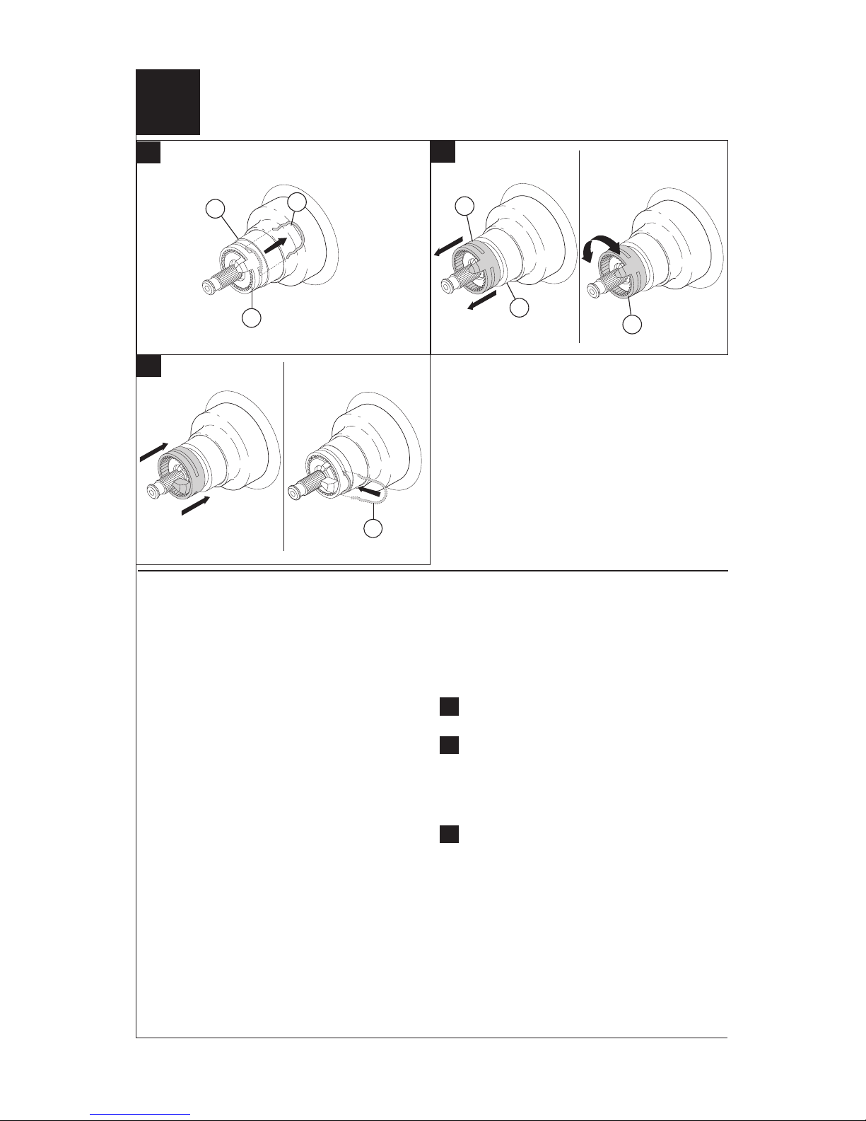
1
A.
B.
C.
D.
4
3
2
3
1
1
2
4
1
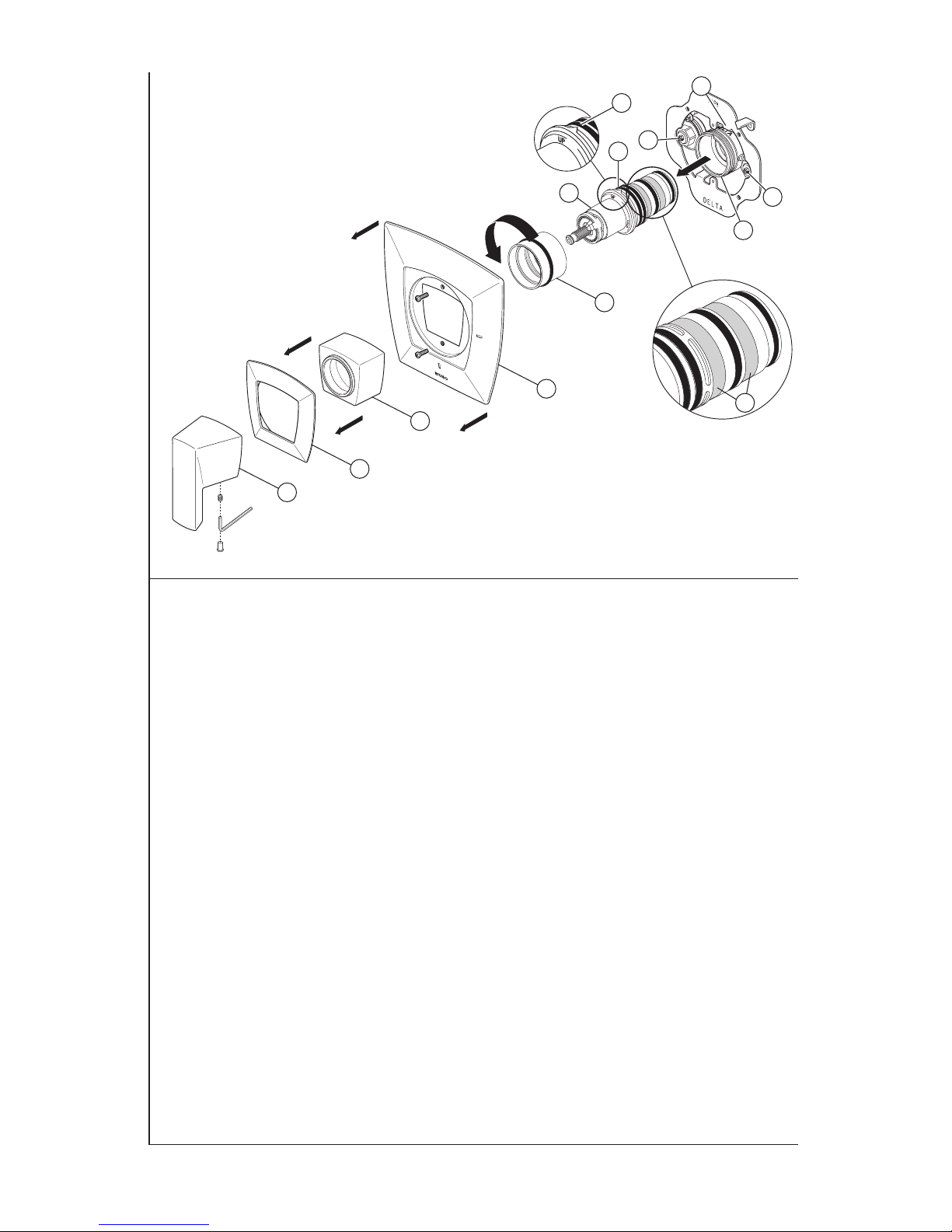
Note: The Sensori® Thermostatic Valve
rough (R66000-WS) must be installed before
installing the trim.
A.
Turn off water supplies from main or
inlet stops (1). Remove plasterguard (2),
bonnet nut (3) and test cap (4) from the
body.
B.
Locate ats (1) on cartridge (2) and inside
of sleeve (3). Align ats and insert cartridge
into sleeve being careful not to push on
copper element at end of cartridge.
C.
Locate “V” (1) on cartridge sleeve and “V”
notch (2) on valve body (3). Align the “Vs”
and press sleeve and cartridge assembly
(4) into valve body (3) and note the “UP”
position (5).
D.
Slide extended bonnet nut (1) over the
cartridge and thread onto the body.
Hand tighten securely.
Do not use original bonnet nut provided
with rough.
3
3
1
1
5
1
2
R66000-WS
Cartridge Installation
2
IMPORTANT:
The Rotational Limit Stop is used to limit the amount
of hot water available such that, if set properly, the
user will not be scalded if the handle accidentally is
rotated all the way to “hot” when a person is showering.
The rst position allows the LEAST amount of hot
water to mix with the cold water in the system. In the
rst position the water will be the coldest possible
when the handle is turned all the way to hot. As you
move the Rotational Limit Stop counterclockwise, you
progressively add more and more hot water in the mix.
The last position to the left will result in the greatest
amount of hot water to the mix, and the greatest risk
of scald injury if someone accidentally turns the valve
handle all the way to the hot side while showering.
WARNING: In some instances, setting the
Rotational Limit Stop in the hottest position (full
counterclockwise) could result in scald injury. It is
necessary to adjust the Rotational Limit Stop so
that the water coming out of the valve will not scald
the user when the handle of the valve is rotated to
the hot side.
• According to the majority of industry standards, the
maximum allowable temperature of the water exiting
the valve is 120°F (Your local plumbing codes may
require a water temperature less than 120°F).
• Run the water so that the cold water is as cold as it
will get and hot water is as hot as it will get. Place the
handle on the stem (see page 6, step 2D) and rotate
the handle counterclockwise until the handle stops.
• Place a thermometer in a plastic tumbler and hold
in the water stream. If the water temperature is above
120°F, the Rotational Limit Stop must be repositioned
clockwise to decrease valve outlet water temperature to
be less than 120°F or to meet the requirements of your
local plumbing codes.
• To adjust the temperature of the water coming out of
the valve:
A.
Pull the clip (1) from the sleeve (2) and rotational
limit stop (3).
B.
Note the position of the rotational limit stop
(3). Pull the rotational limit stop out from the
sleeve (2) enough so that it can be rotated
clockwise to decrease the outlet temperature
or counterclockwise to increase the outlet
temperature.
C.
Once the desired outlet temperature is reached,
make sure rotational limit stop is pushed back onto
the sleeve so that the clip (1) can be reinstalled.
Make sure clip is secure on sleeve. Reassemble
handle to valve stem.
• MAKE SURE COLD WATER FLOWS FROM THE
VALVE FIRST. MAKE SURE WATER FLOWING FROM
THE VALVE AT THE HOTTEST FLOW POSSIBLE
DOES NOT EXCEED 120°F OR THE MAXIMUM
ALLOWED BY YOUR LOCAL PLUMBING CODE.
C.
B.
A.
1
3
3
3
1
2
2
4
91844 Rev. A
Installation and Adjustment of the Rotational Limit Stop
Mounting Bracket Installation
A.
3
A.
Place bracket against nished wall so
that the holes in legs of bracket align
with threaded holes on the rough. Use
two long screws provided to secure the
bracket to the rough.
Do not overtighten screws.
Ensure that the bracket lays at against
the nished wall.
5
91844 Rev. A
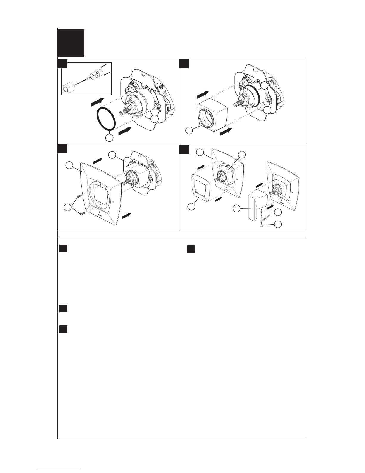
1
2
6
91844 Rev. A
A.
Slide O-ring (1) over bonnet nut (2) and
position it in groove on bonnet nut (2).
The O-ring, acts as a spacer to steady
the trim sleeve.
Note: Depending on location of valve
within the wall and wall thickness, an
optional extension kit may be needed.
RP91023▲ will provide up to 1-3/4" of
extension.
B.
Slide trim sleeve (3), over the bonnet
nut (2) and O-ring (1). Ensure sleeve is
securely positioned over cartridge.
C.
Place the escutcheon (4) on wall and
secure to the mounting bracket (5) using
the 2 short screws (6) provided. Do not
overtighten.
D.
Slide screw cover (7) over trim sleeve (3)
and press firmly until the cover is flush with
escutcheon (4). O-ring will hold screw cover
in place.
Before installing handle, ensure valve
is in the full cold position (clockwise).
Orient handle (8) so the lever is pointing
downward and press handle onto splined
stem of cartridge. Secure handle with set
screw provided (9) and press button (10)
into hole.
B.
D.
Optional Extension
Kit Available -
RP91023▲
C.
A.
Trim Installation
4
5
4
6
7
8
10
9
4
2
1
3
3
7
91844 Rev. A
Cleaning and Care
Care should be given to the cleaning of this
product. Although its finish is extremely durable,
it can be damaged by harsh abrasives or polish.
To clean, simply wipe gently with a damp cloth
and blot dry with a soft towel.
Maintenance
If you notice reduced ow or the outlet
temperature uctuating, the cartridge screens
may need cleaned. To clean the cartridge
screens:
Shut off water from the main valve or from stops
(1). Stops may be accessed after removing
trim. Remove the handle (2), screw cover (3),
trim sleeve (4), escutcheon (5) and unscrew
bonnet nut (6). Carefully pull cartridge and sleeve
assembly (7) from the valve body (8). Carefully
brush or wash away any debris that may be on
the screens (9). After cleaning, reinstall cartridge
and sleeve assembly back into the valve body,
making sure to align the “V” (10) on the sleeve
with the “V” groove (11) on the valve body (Note
the “UP” on the sleeve). Secure cartridge and
sleeve assembly by screwing the bonnet securely
onto the valve body. Turn the stops on, and
reassemble remaining parts.
1
7
9
10
10
11
8
1
2
3
4
5
6
1
91844 Rev. A
ACCESORIO DE LA VÁLVULA
TERMOSTÁTICA SENSORI
®
1/30/2017
5/32"
(3.97mm)
Usted puede necesitar:
ADVERTENCIA: El instalador debe apostar este systema/
divisa para garantizar temperatura maximo y seguro.
Cualqueir cambio en el ajuste puede subir la temperatura
del agua de descarga sobre el límite considerado seguro y
puede resultar en quemaduras de agua caliente.
AVISO PARA EL INSTALADOR: PRECAUCIÓN – Como
instalador de esta válvula, es su responsabilidad
de INSTALAR Y AJUSTAR apropiadamente esta
válvula como se describe en las instrucciones, por
lo tanto, debe haber una persona para hacer los
ajustes necesarios del pomo para la temperatura en el
momento que se haga la instalación y pueda necesitar
ajustes adicionales por los cambios estacionales
de la temperatura del agua. USTED DEBE informarle
al dueño/usuario sobre este requisito siguiendo las
instrucciones. Si usted o el dueño/usuario no están
seguros como hacer estos ajustes apropiadamente, por
favor reérase al Página 4 y si todavía no está seguro,
llámenos al 1-877-345-BRIZO (2749).
Después de hacer la instalación y el ajuste, usted puede
agregarle a la etiqueta de aviso proporcionada, su nombre,
el nombre de la compañía y la fecha cuando ajustó y el pomo
para la temperatura y aplicar o jar la etiqueta al dorso de
la puerta del gabinete más cercano y la etiqueta de aviso
al calentador de agua. Deje la Hoja de Instrucciones para
referencia del dueño/usuario.
ADVERTENCIA: Esta válvula termostática está
diseñada para minimizar los efectos de los cambios
de temperatura de agua por causa de los cambios
de temperatura en el agua de entrada, comúnmente
causados por lavadoras de platos, lavadoras de ropa,
inodoros, y otros aparatos por el estilo. Puede no
proporcionar protección de quemaduras de agua caliente
cuando hay alguna falla de otros aparatos para el control
de temperatura en otro sitio en el sistema de plomería.
También no proporcionará protección si el pomo para el
ajuste de la temperatura no está apropiadamente jo o
si cambia la temperatura del agua caliente después de
hacer los ajustes o si los cambios del agua de entrada
son por los cambios estacionales.
ADVERTENCIA: No instale un aparato de corte o cierre
en cualquiera de las tomas de esta válvula. Cuando este
tipo de aparato cierra el ujo de agua, puede hacer fallar
la habilidad de la válvula de balancear las presiones del
agua caliente y fría.
Contenido:
Garantía ............................................................................. Página 2
Instrucciones de Instalación................................................ Páginas 3 - 5
Mantenimiento..................................................................... Página 6
Piezas de Repuesto............................................................ Páginas 7-8
Modelos
T66T088▲
Series
VETTIS
™
91844
▲Especifíque el Acabado
Para instalación fácil de su llave Brizo® usted necesitará:
• LEER TODAS las instrucciones completamente antes de empezar
• LEER TODOS los avisos, cuidados, e información de mantenimiento.
Escriba aquí el número del modelo comprado.
 Loading...