

Brizo Charlotte T60085, Charlotte T60285, Charlotte T60485 Installation Instructions And Owner's Manual
Page 1
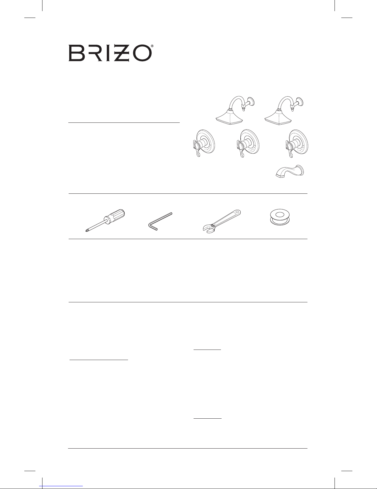
MultiChoice® Valve Trim
Installation Instructions
Owners Manual
Charlotte™
Write purchased model number here.
ASME A112.18.1 / CSA B125.1
ASSE 1016 TYPE T
Table of Contents:
Warranty ............................................................................. Page 2
Installation Instructions ....................................................... Pages 3 - 6
Maintenance ....................................................................... Page 6
Replacement Parts ............................................................. Page 7
1
You May Need
3/4/13
75651 Rev. A
THIS VALVE MEETS OR EXCEEDS THE
FOLLOWING STANDARDS:
ASME A112.18.1/CSA B125.1 and ASSE 1016.
CAUTION: This system/device must be set by the
installer to ensure safe, maximum temperature.
Any change in the setting may raise the discharge
temperature above the limit considered safe and
may lead to hot water burns.
NOTICE TO INSTALLER: CAUTION!–As the
installer of this valve, it is your responsibility
to properly INSTALL and ADJUST this valve
per the instructions given. This valve does
not automatically adjust for inlet temperature
changes, therefore, someone must make the
necessary temperature knob adjustments at
the time of installation and further adjustments
may be necessary due to seasonal water
temperature change. YOU MUST inform the
owner/user of this requirement by following the
instructions. If you or the owner/user are unsure
how to properly make these adjustments, please
refer to page 6 and if still uncertain, call us at
1-877-345-BRIZO (2749).
After installation and adjustment, you must affix
your name, company name and the date you
adjusted the temperature knob to the caution label
provided and apply or attach the label to the back
side of the closest cabinet door and the warning
label to the water heater. Leave this Instruction
Sheet for the owner’s/user’s reference.
WARNING: This thermostatic bath valve is
designed to minimize the effects of outlet water
temperature changes due to inlet pressure and
temperature changes, commonly caused by
dishwashers, washing machines, toilets and
the like. It may not provide protection from hot
water burns when there is a failure of other
temperature controlling devices elsewhere
in the plumbing system, if the temperature
knob is not properly set or if the hot water
temperature is changed after the settings
are made or if the water inlet changes due to
seasonal changes.
WARNING: Do not install a shut-off device on
either outlet of this valve. When this type of
device shuts off the water flow, it can defeat
the ability of the valve to balance the hot and
cold water pressures.
For easy installation of your Brizo® faucet
you will need:
• To READ ALL the instructions completely
before beginning.
• To READ ALL warnings,care, and
maintenance information.
T60085
T60285 T60485
Page 2

www.brizo.com
2
All parts and finishes of the Brizo® faucet are
warranted to the original consumer purchaser to
be free from defects in material & workmanship
for as long as the original consumer purchaser
owns their home. Delta Faucet Company
recommends using a professional plumber for
all installation & repair.
Delta will replace, FREE OF CHARGE,
during the warranty period, any part or finish
that proves defective in material and/or
workmanship under normal installation, use
and service. Replacement parts may be
obtained by calling 1-877-345-BRIZO (2749)
(in the U.S. and Canada) or by writing to:
In the United States:
Delta Faucet Company
Product Service
55 E. 111th Street
Indianapolis, IN 46280
In Canada:
Masco Canada Limited, Plumbing Group
350 South Edgeware Road,
St. Thomas, Ontario, Canada N5P 4L1
This warranty is extensive in that it covers
replacement of all defective parts and even finish,
but these are the only two things that are
covered. LABOR CHARGES AND/OR DAMAGE
INCURRED IN INSTALLATION, REPAIR, OR
REPLACEMENT AS WELL AS ANY OTHER
Lifetime Faucet and Finish Limited Warranty
KIND OF LOSS OR DAMAGES ARE
EXCLUDED. Proof of purchase (original sales
receipt) from the original consumer purchaser
must be made available to Delta for all warranty
claims. THIS IS THE EXCLUSIVE WARRANTY
BY DELTA FAUCET COMPANY, WHICH DOES
NOT MAKE ANY OTHER WARRANTY OF ANY
KIND, INCLUDING THE IMPLIED WARRANTY
OF MERCHANTABILITY.
This warranty excludes all industrial, commercial
& business usage, whose purchasers are hereby
extended a five year limited warranty from the
date of purchase, with all other terms of this
warranty applying except the duration of the
warranty. This warranty is applicable to Brizo®
faucets manufactured after January 1, 1995.
Some states/provinces do not allow the exclusion
or limitation of incidental or consequential
damages, so the above limitation or exclusion
may not apply to you. Any damage to this faucet
as a result of misuse, abuse, or neglect, or any
use of other than genuine Delta® replacement
parts WILL VOID THE WARRANTY.
This warranty gives you specific legal rights, and
you may also have other rights which vary from
state/province to state/province. It applies only for
Brizo® faucets installed in the United States of
America, Canada, and Mexico.
© 2013 Masco Corporation of Indiana
Cleaning and Care
Care should be given to the cleaning
of this product. Although its finish is
extremely durable, it can be damaged by
harsh abrasives or polish. To clean, simply
wipe gently with a damp cloth and blot dry
with a soft towel.
Page 3
3
B.
1
4
4
2
3
60 Series Installation
1
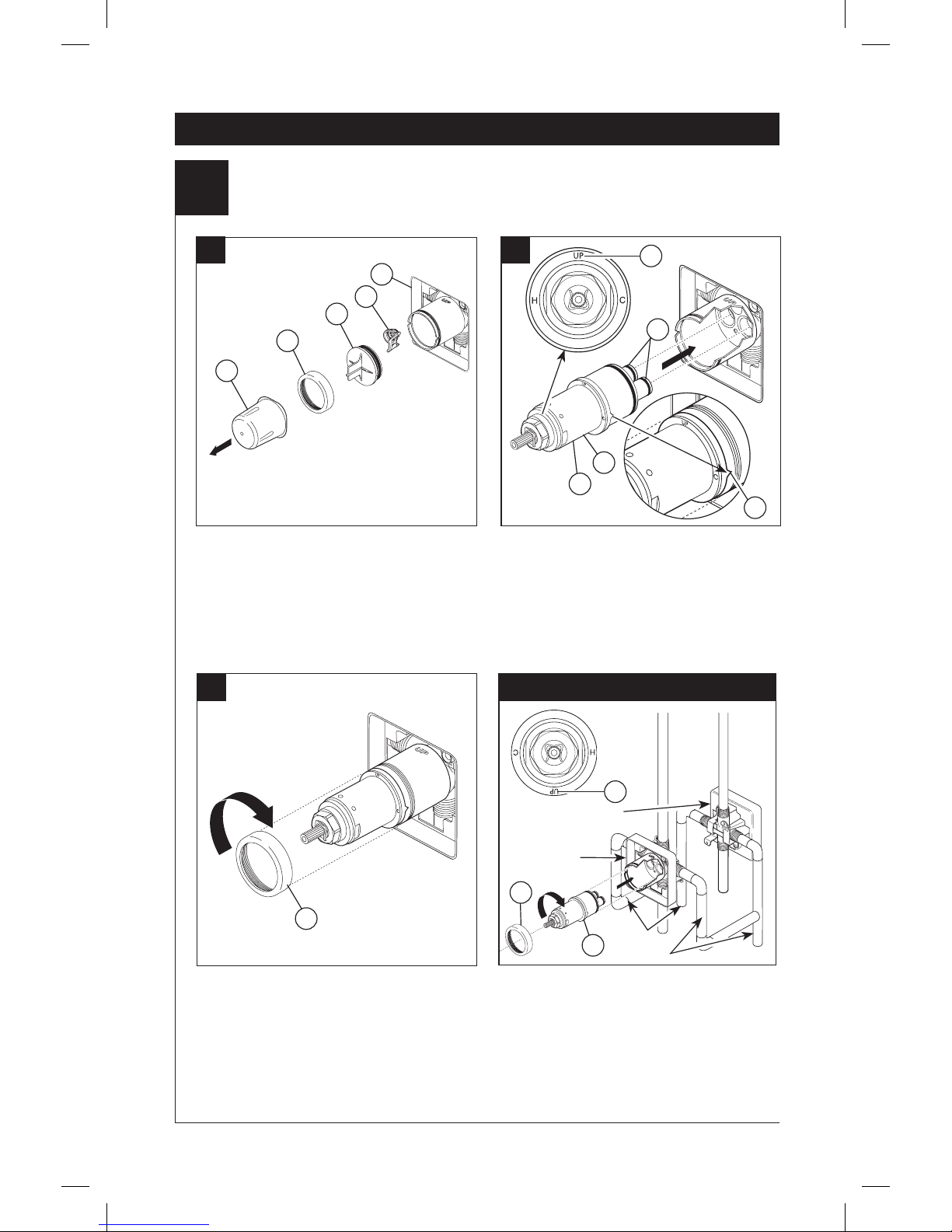
Cartridge Installation
A.
Turn off water supplies. Remove cover (1),
bonnet nut (2) and test cap (3) from the body. If
this is not a thin wall mounting, the entire plasterguard (4) may be removed. If screen (5) is in
place, remove before installing cartridge.
1
2
3
4
Rotate the cartridge (1) so the word “UP” (2)
appears on the top. Insert cartridge into valve
body as shown. Make sure the cartridge tubes
and O-rings (3) are properly seated in holes at
the base of the body. Ensure the keys on the
body are fully engaged with the slots in the
body (4).
For back to back or reverse installations
(hot on right and cold on left): Rotate cartridge
(1) so the word “UP” (2) appears on the bottom.
Install the cartridge making sure that the keys are
fully engaged with the slots in the brass body (see
step B). Slide bonnet nut (3) over the cartridge and
thread onto the body. Hand tighten securely.
Back to back Installation
Normal Installation
(changes not required)
Reverse
Installation
Cold
Hot
1
3
2
C.
Slide bonnet nut (1) over the cartridge and
thread onto the body. Hand tighten securely.
1
5
Page 4
4
60 Series Installation
2
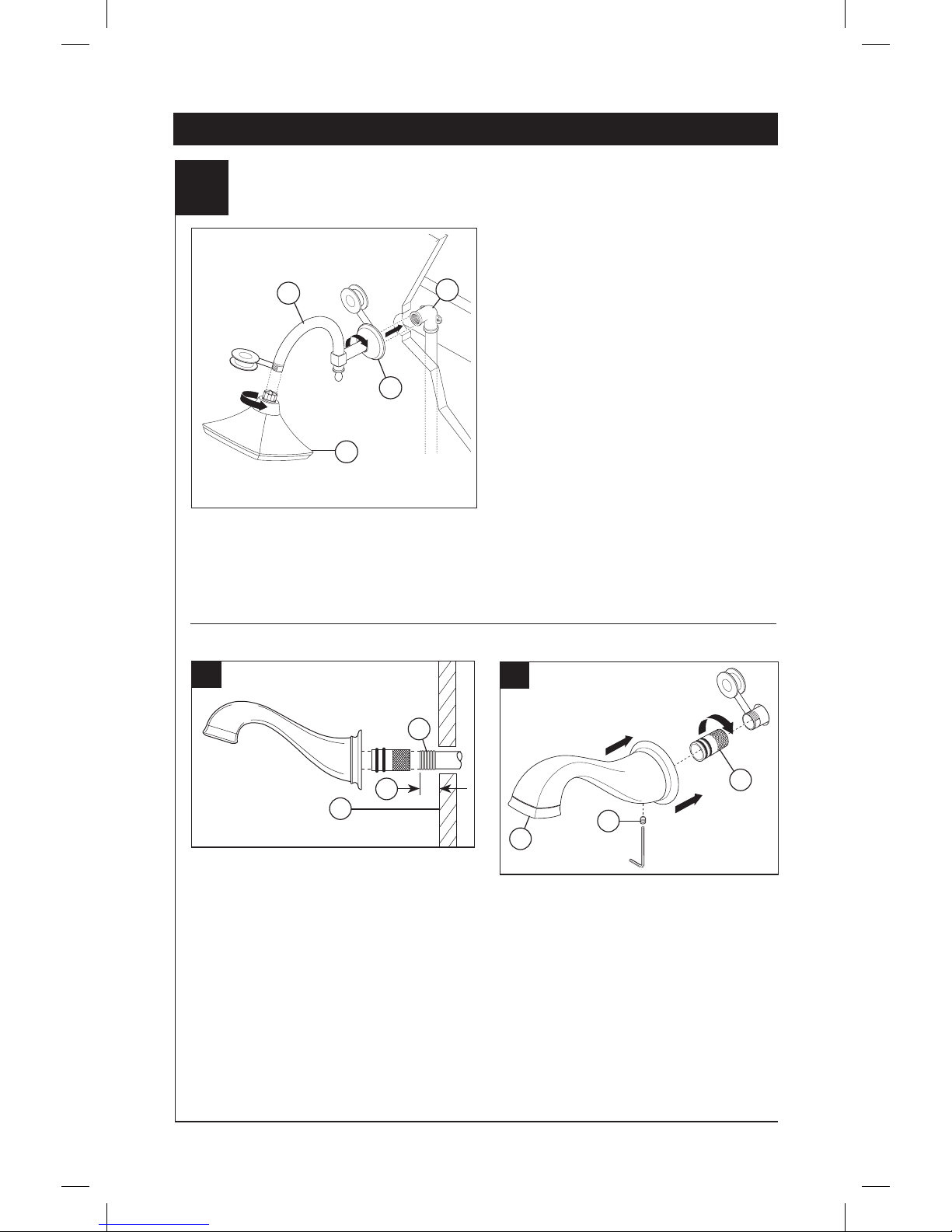
Showerhead and Tub Spout Installation
FOR TUB SPOUT INSTALLATION:
Install 1/2" (13 mm) threaded pipe nipple (1) to
extend past finished wall (2) per dimension (3).
Connection of deck mount spouts to in–wall
valves is not recommended. Neither is the use
of hand showers connected to tub spouts in a
tub/shower push button diverter combination, or
hand showers connected in lieu of a tub spout
to a tub / shower valve.
Piping between valve body and tub spout must
be a minimum of 1/2" (13 mm) copper pipe
or 1/2" (13 mm) iron pipe in a straight drop
no less than 8" (203 mm) but no more than
18" (457 mm) long with only one iron pipe or
copper 90 degree elbow to the tub spout nipple.
1
2
3
4
1
3
(3) = 3/8
" - 1/2" (9.5 mm - 12.7 mm)
2
RP70908s
A.
B.
Install a 1/2" threaded pipe nipple to extend
beyond the finished wall 3/8" to 1/2". Apply
plumber tape to thread on pipe nipple and screw
brass adapter (1) securely onto nipple. Install set
screw on bottom of spout (2) making sure it is not
sticking through to the inside opening where it
could interfere with the assembly. Slide tub spout
over the adapter and tighten set screw, on bottom
of spout, against the adapter. Note: This spout
utilizes a pull down diverter mechanism. To
divert from spout to shower, pull down on
spout tip (3).
1
2
3
NOTE: It is suggested that you anchor your shower arm and tub spout
elbows or water lines.
FOR SHOWERHEAD INSTALLATION:
Connect top outlet (1) to shower arm (2) with
proper fittings. Apply plumber tape to pipe
threads on both ends of showerarm. To prevent
damage to finish on shower arm, insert wall end
of shower arm into shower flange (3) before
screwing arm into riser connection. Thread
showerhead (4) onto shower arm. Do not
overtighten showerhead.
Page 5
5
C.
D.
A.
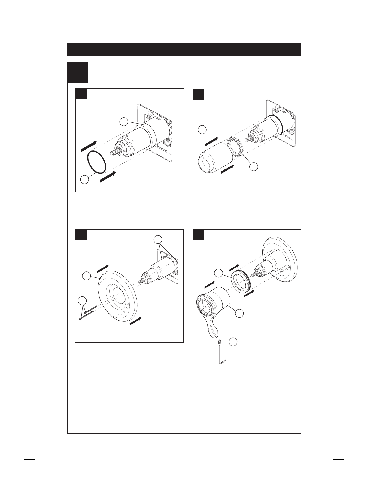
B.
Slide O-ring (1) over cartridge and the bonnet
nut (2). The O-ring, which acts as a spacer to
steady the sleeve, should rest behind the
bonnet nut.
If your model requires a spacer (1), install it into
sleeve (2). Slide the sleeve over the cartridge, body
and O-ring. Ensure sleeve is properly positioned
over the front of cartridge.
Secure the escutcheon (1) to the bracket (2) with
the 2 screws provided (3). Do not overtighten
escutcheon screws.
Slide trim ring (1) over the cartridge and sleeve
and into the escutcheon. Install volume control
handle (2) with lever pointed downward to 6
o’clock position. Install set screw (3) into handle.
Push handle onto valve cartridge and tighten set
screw to secure handle.
3
Valve Trim Installation
1
2
2
1
2
2
3
60 Series Installation
1
1
3
Page 6
6
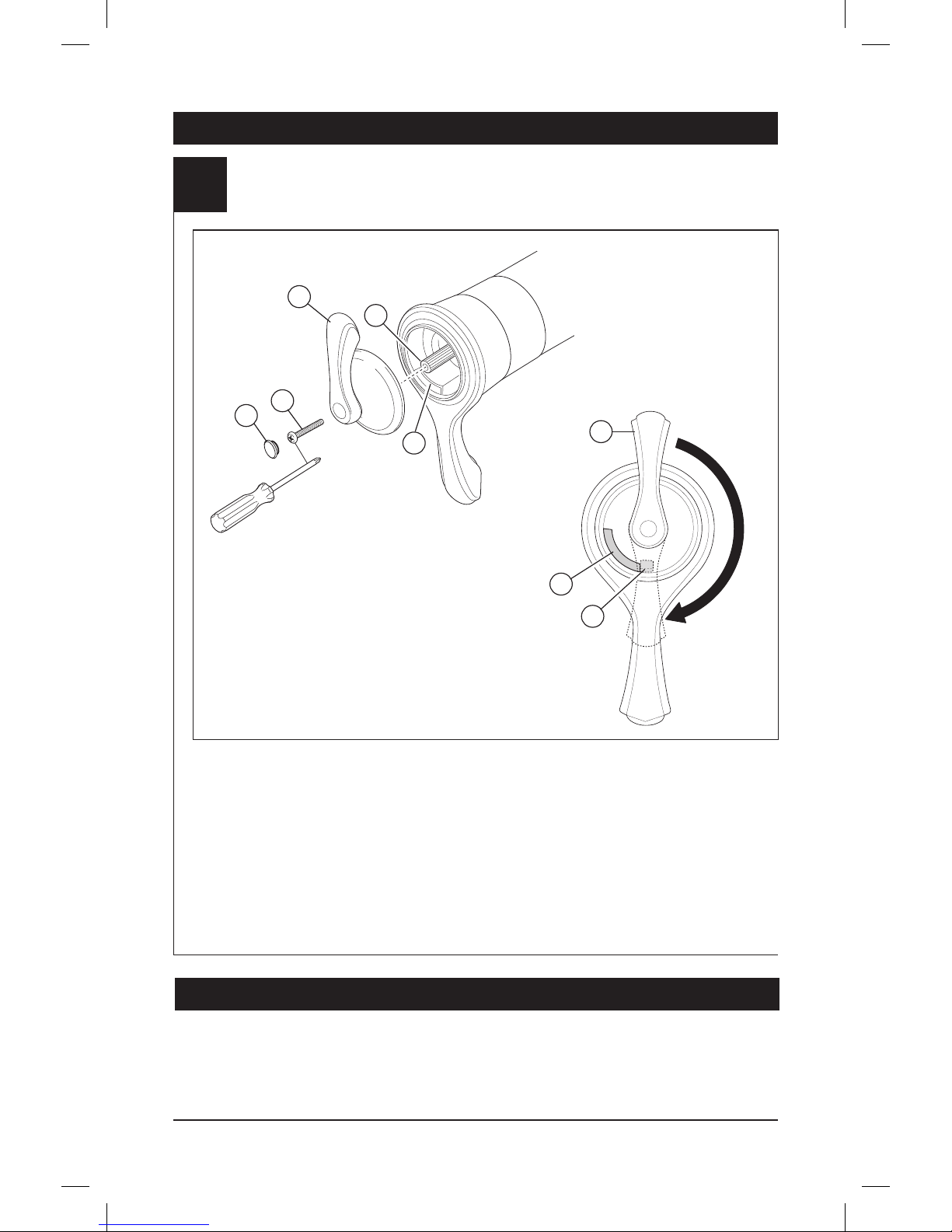
4
Installation and Adjustment of the Temperature Knob
Failure to do so may cause injury.
60 Series Installation
Adjust temperature limit stop. Turn on water
supplies; let the water run at both full hot and
full cold to ensure the water is running as hot/
cold as possible. Place a thermometer in a
plastic tumbler, and hold the tumbler in the water
stream. Place the temperature knob (1) onto the
splines (2), then rotate the temperature knob
until you achieve your maximum desired
temperature from the outlet (not more than 120°
or the lower temperature mandated by your local
plumbing code). Remove the temperature knob
and replace onto the splines (2), making sure that
the temperature knob limit stop (3) hits against
the volume handle limit stop (4) as shown.
Note: Temperature lever is intended to point
upward near 12 o’clock position. Once desired
position is acquired per instructions above, thread
screw (5) into handle (1) and secure it to valve
stem by tightening screw. Insert button (6) into
screw hole.
1
3
2
1
4
5
6
60 Series Maintenance
Faucet leaks from showerhead or tub spout:
SHUT OFF WATER SUPPLIES. Replace Cartridge
Assembly –Repair Kit RP47201.
If water does not flow:
Verify that the hot side of the cartridge is installed
on the hot water supply line. If it is not, turn off
water supplies and flip cartridge.
4
Page 7

Instrucciones para la
Instalación del Accesorio
para Válvulas MultiChoice
®
Manual para los Propietarios
Charlotte™
Escriba aquí el número del modelo comprado.
ASME A112.18.1 / CSA B125.1
ASSE 1016
Contenido:
Garantía ............................................................................. Página 2
Instrucciones de Instalación................................................ Páginas 3 - 6
Mantenimiento..................................................................... Página 6
Piezas de Repuesto............................................................ Página 7
1
Usted puede necesitar
3/4/13
75651 Rev. A
ESTA VÁLVULA CUMPLE O EXCEDE LAS
SIGUIENTES NORMAS:
ASME A112.18 1 / CSA B125.1 y ASSE 1016.
ADVERTENCIA: El instalador debe apostar
este systema/divisa para garantizar temperatura
maximo y seguro. Cualqueir cambio en el ajuste
puede subir la temperatura del agua de descarga
sobre el límite considerado seguro y puede resultar
en quemaduras de agua caliente.
AVISO PARA EL INSTALADOR: PRECAUCIÓN
– Como instalador de esta válvula, es su
responsabilidad de INSTALAR Y AJUSTAR
apropiadamente esta válvula como se describe
en las instrucciones, por lo tanto, debe
haber una persona para hacer los ajustes
necesarios del pomo para la temperatura en el
momento que se haga la instalación y pueda
necesitar ajustes adicionales por los cambios
estacionales de la temperatura del agua. USTED
DEBE informarle al dueño/usuario sobre este
requisito siguiendo las instrucciones. Si usted
o el dueño/usuario no están seguros como
hacer estos ajustes apropiadamente, por favor
refiérase al Página 6 y si todavía no está seguro,
llámenos al 1-877-345-BRIZO (2749).
Después de hacer la instalación y el ajuste,
usted puede agregarle a la etiqueta de aviso
proporcionada, su nombre, el nombre de la
compañía y la fecha cuando ajustó y el pomo para
la temperatura y aplicar o fijar la etiqueta al dorso
de la puerta del gabinete más cercano y la etiqueta
de aviso al calentador de agua. Deje la Hoja de
Instrucciones para referencia del dueño/usuario.
ADVERTENCIA: Esta válvula termostática está
diseñada para minimizar los efectos de los
cambios de temperatura de agua por causa
de los cambios de presión y de temperatura
en el agua de entrada, comúnmente causados
por lavadoras de platos, lavadoras de ropa,
inodoros, y otros aparatos por el estilo. Puede
no proporcionar protección de quemaduras
de agua caliente cuando hay alguna falla de
otros aparatos para el control de temperatura
en otro sitio en el sistema de plomería. También
no proporcionará protección si el pomo para el
ajuste de la temperatura no está apropiadamente
fijo o si cambia la temperatura del agua caliente
después de hacer los ajustes o si los cambios
del agua de entrada son por los cambios
estacionales.
ADVERTENCIA: No instale un aparato de corte
o cierre en cualquiera de las tomas de esta
válvula. Cuando este tipo de aparato cierra el
flujo de agua, puede hacer fallar la habilidad de
la válvula de balancear las presiones del agua
caliente y fría.
Para instalación fácil de su llave Brizo®
usted necesitará:
• LEER TODAS las instrucciones completamente
antes de empezar
• LEER TODOS los avisos, cuidados,
e información de mantenimiento.
T60085 T60285 T60485
Page 8

www.brizo.com
2
Todas las piezas y acabados de la llave Brizo®
están garantizados al consumidor comprador
original, de estar libres de defectos de material y
fabricación, por el tiempo que el consumidor
comprador original sea dueño de su casa. Delta
Faucet Company recomienda que use un
plomero profesional para todas las instalaciones
y reparaciones.
Delta reemplazará, LIBRE DE CARGO, durante el
período de garantía, cualquier pieza o
acabado que pruebe tener defectos de material y/
o fabricación bajo instalación normal, uso y
servicio. Piezas de repuesto pueden ser obtenidas
llamando al 1-877-345-BRIZO (2749) (en los
Estados Unidos y Canada) o escribiendo a:
En los Estados Unidos:
Delta Faucet Company
Product Service
55 E. 111th Street
Indianapolis, IN 46280
En Canada:
Masco Canada Limited, Plumbing Group
350 South Edgeware Road,
St. Thomas, Ontario, Canada N5P 4L1
Esta garantía es extensiva en lo que cubre el
reemplazamiento de todas las piezas
defectuosas y hasta el acabado, pero éstas son
las únicas dos cosas que están cubiertas.
CARGOS DE LABOR Y/O DAÑOS INCURRIDOS
EN LA INSTALACIÓN, REPARACIÓN, O
REEMPLAZAMIENTO COMO TAMBIÉN
CUALQUIER OTRO TIPO DE PÉRDIDA O
GarantÍa Limitada De Por Vida de la Llave y su Acabado
DAÑOS ESTÁN EXCLUÍDOS. Prueba de compra
(recibo original de venta) del comprador
consumidor original debe de ser disponible a
Delta para todos los reclamos. ESTA ES LA
GARANTÍA EXCLUSIVA DE DELTA FAUCET
COMPANY, QUE NO HACE CUALQUIER OTRA
GARANTÍA DE CUALQUIER TIPO,
INCLUYENDO LA GARANTÍA IMPLÍCITA DE
COMERCIALIZACIÓN.
Esta garantía excluye todo uso industrial,
comercial y de negocio, a cuyos compradores se
les da una garantía limitada extendida de cinco
años desde la fecha de compra, con todos los
otros términos de esta garantía aplicados,
excepto el de duración de ésta. Esta garantía es
aplicable a las llaves de Brizo® fabricadas
después de Enero 1, 1995.
Algunos estados/provincias no permiten la
exclusión o limitación de daños incidentales o
consecuentes, de manera que la limitación o
exclusión arriba escrita puede no aplicarle a
usted. Cualquier daño a esta llave, resultado del
mal uso, abuso, o descuido, o cualquier otro uso
de piezas de repuesto que no sean genuinas de
Delta® ANULARÁN LA GARANTÍA.
Esta garantía le da derechos legales específicos,
y usted puede, también tener otros
derechos que varían de estado/provincia a
estado/provincia. Es aplicable sólo a las llaves
Brizo® instaladas en los Estados Unidos de
America, Canada y Mexico.
© 2013 Masco Corporación de Indiana
Limpieza y Cuidado de su Llave
Tenga cuidado al ir a limpiar este producto.
Aunque su acabado es sumamente
durable, puede ser afectado por agentes de
limpieza o para pulir abrasivos. Para limpiar
su llave, simplemente frótela con un
trapo húmedo y luego séquela con una
toalla suave.
Page 9

3
B.
1
4
4
2
3
Instalación de la Serie 60
1
Instalación del Cartucho
A.
Cierre los suministros de agua. Quite la cubi-
erta (1), la tuerca tapa (2) y la tapa de prueba (3).
Si no es para instalar en pared delgada, puede
quitar el protector (4) de yeso completo. Si la
pantalla (5) está en lugar, quite antes de instalar
el cartucho.
1
2
3
4
Gire el cartucho (1) de manera que la palabra “UP”
(2) aparezca encima. Introduzca el cartucho en el
cuerpo de la válvula como se muestra. Asegúrese
que los tubos del cartucho y los aros O (3) estén
debidamente sentados en los agujeros en la base
del cuerpo. Asegúrese que los dentados estén
completamente encajados en las muescas del
cuerpo (4).
En las instalaciones dorso con dorso (el agua
caliente en la derecha y la fría en la izquierda):
Gire el cartucho (1) así que la palabra “UP”
de (2) aparece en el fondo. Instale el cartucho
asegurándose que los dentados estén
completamente enganchados en las muescas en
el cuerpo de bronce (vea la página B). Deslice la
tuerca tapa (3) sobre el cartucho y enrosque en el
cuerpo de la válvula. Apriete a mano bien.
Instalación de Espalda a Espalda
Instalación Normal
(No serequerá cambios)
Instalación
Invertido
Fría
Caliente
1
3
2
C.
Deslice la tuerca tapa (1) sobre el
cartucho y enrosque en el cuerpo de la válvula.
Apriete a mano bien.
1
5
Page 10

4
Instalación de la Serie 60
2
Instalación de la Cabeza de la Regadera y el Surtidor de la Bañera
PARA LA INSTALACIÓN DE REGADERA:
Conecte la salida superior (1) al brazo de la regadera o ducha (2) con los accesorios apropiados.
Aplique cinta para plomero a las roscas en ambos
extremos del brazo de la regadera. Para prevenir
daño al acabado del brazo de la regadera, inserte el
extremo que va hacia la pared, en la brida de la regadera (3) antes de atornillar el brazo en la conexión
vertical. Atornille la cabeza de la regadera (4) en el
brazo de esta. No la apriete demasiado.
PARA LA INSTALACIÓN DEL
SURTIDOR DE LA BAÑERA:
Instale una entrerrosca de tubo de 1/2” (13 mm) (1)
de manera que sobresalga la pared acabada (2)
como en la dimensión (3).
No se recomienda la conexión en paredes de tubos
de salida que son para la instalación en el área
de los bordes. Tampoco se recomienda el uso de
regaderas de mano conectadas a los tubos de
salida de bañeras, en combinación bañera/regadera,
con desviador de botón a presión, o regaderas de
mano conectadas en lugar de un tubo de salida de
bañera a una válvula de bañera/regadera.
La tubería entre el cuerpo de la válvula y el tubo de
salida de la bañera debe ser de tubo de cobre de un
mínimo de 1/2” (13 mm) o tubo de hierro de 1/2” (13
mm) en caída recta no menos de 8” (203 mm) pero
no más de 18” (457 mm) de largo con sólo un codo
de 90°, de hierro o cobre, a la entrerrosca del tubo
de salida de agua.
1
3
(3) = 3/8
" - 1/2" (9.5 mm - 12.7 mm)
2
RP62605s
A.
B.
Instale una entrerrosca de 1/2" de manera que
sobresalga de 3/8" a 1/2" de la pared terminada.
Aplique cinta de plomero en el roscado de la
entrerrosca y atornille el adaptador de latón en
la entrerrosca (1). Revise la posición del tornillo
de ajuste en el fondo del surtidor (2)
asegurándose que no se está pegando a la
parte interior de la abertura donde podría
interferir con en ensamble. Deslice el surtidor de
la bañera sobre el adaptador y apriete el tornillo
de ajuste, en la parte inferior del surtidor, contra
el adaptador. Nota: Este surtidor utiliza un
mecanismo de desvío que se hala hacia
abajo. Para desviar del surtidor a la regadera,
hale la salida en el surtidor (3).
1
2
3
NOTA: Se sugiere que ancle el brazo de su regadera y los codos del
surtidor de la bañera o las líneas de agua.
1
2
3
4
Page 11

5
C.
A.
Deslice el aro O (1) sobre el cartucho y la
tuerca tapa (2). El aro O, el cual funciona como
un separador para estabilizar la manga, debe
quedar apoyado en la tuerca tapa.
Fije la roseta con orificio (1) al soporte (2)
usando los 2 tornillos suministrados (3). No
apriete demasiado los tornillos de la roseta.
3
Instalación Final
1
2
1
2
3
Instalación de la Serie 60
B.
Si su modelo requiere un separador (1), insértelo en
la manga (2). Deslice la manga sobre el cartucho, el
cuerpo de la pieza y el aro O. Asegure la cubierta de
ajuste se coloca correctamente sobre el frente del
cartucho de la ducha.
2
1
Deslice el anillo de accesorio (1) sobre el
cartucho y la manga y en la chapa de cubierta.
Instale la manija del control del volumen (2) con
la palanca apuntando hacia abajo, en la posición
de las 6 en el reloj. Instale de tornillo de ajuste (3)
en la manija. Presione la manija en el cartucho
de la válvula y apriete el tornillo de ajuste para
fijar la manija.
D.
2
1
3
Page 12

6
4
Instalación y Ajuste del Pomo de Temperatura
El no hacerlo puede causar lesión.
Instalación de la Serie 60
¡Ajuste el tope del límite de temperatura.
Abra los suministros de agua, deje correr el
agua, tanto la caliente como la fría a lo máximo,
para garantizar que el agua está saliendo lo más
caliente / fría posible. Coloque un termómetro
en un vaso plástico, y sostenga el vaso en el
chorro de agua. Coloque la perilla o control de
la temperatura (1) en las ranuras (2), luego, gire
la perilla de temperatura hasta que logre su
temperatura máxima deseada desde la toma
(no más de 120° o la temperatura más baja
autorizada por su código local de plomería).
Retire la perilla de temperatura y vuelva a
colocarla en las ranuras (2), asegurándose que la
perilla o control del tope del límite de temperatura
(3) queda situada contra la manija del control
de volumen (4), como se muestra. Nota: la
palanca de temperatura debe señalar hacia
arriba, cerca de las 12 en punto. Una vez que la
posición deseada se adquiere, como establecida
en las instrucciones arriba, atornille el tornillo (5)
en el mango (1) y fíjelo a la espiga de la válvula
apretando el tornillo. Inserte el botón (6) en el
agujero del tornillo.
Mantenimiento de la Serie 60
Si la llave de agua tiene una filtración o
escape de agua desde el surtidor o la cabeza
de la regadera:
CIERRE LOS SUMINISTROS DE AGUA. Cambie
el Ensamble del cartucho – Piezas de Repuesto
RP47201.
Si no fluye el agua:
Verifique que el lado caliente del cartucho
esté instalado en la línea de fuente de la agua
caliente. Si no es, dé vuelta apagado a los
abastecimientos de agua y mueva de un tirón
el cartucho.
1
3
2
1
4
5
6
4
Page 13

Instructions d’installation
Finition de la soupape
MultiChoice
®
Guide d’utilisation
Charlotte™
Inscrivez le numéro de modèle ici.
ASME A112.18.1 / CSA B125.1
ASSE 1016
Table des matières
Garantie ............................................................................. Page 2
Instructions d’installation .................................................... Pages 3 - 6
Maintenance ....................................................................... Page 6
Pièces de rechange ........................................................... Page 7
1
Articles dont vous pouvez avoir besoin:
3/4/13
75651 Rev. A
Ce robinet satisfait aux exigences des normes
ASME A112.18.1/CSA B125.1 et ASSE 1016 ou
les surpasse.
ATTENTION: L’installateur doit régler l’appareil
pour que la température maximale de l’eau chaude
soit sans danger. Toute modification des réglage
peut entraîner une élévation de la température à
la sorite du robinet au delà de la température sans
danger et pourrait causer un échaudage.
AVIS À L’INSTALLATEUR : ATTENTION! – En
qualité d’installateur, vous êtes tenu
d’INSTALLER et de RÉGLER ce robinet
conformément aux instructions. Ce robinet ne
s’adapte pas automatiquement aux fluctuations
de la température de l’eau d’alimentation. Par
conséquent, il faut régler le bouton de
température au moment de l’installation et il
peut être nécessaire de faire de nouveaux
réglages par la suite en raison des fluctuations
saisonnières de la température de l’eau. VOUS
DEVEZ informer le propriétaire ou l’utilisateur
de cette exigence. En cas de doute quant à la
marche à suivre pour faire ces réglages,
veuillez consulter page 6 si un doute persiste,
et si cette incertitude persiste, appelez-nous au
1-877-345-BRIZO (2749).
Après avoir terminé l’installation et le réglage, vous
devez inscrire, sur l’étiquette de mise en garde
fournie, votre nom, le nom de votre entreprise et la
date à laquelle vous avez réglé le bouton de
température, puis fixer l’étiquette à l’endos de la
porte de la coiffeuse. Vous devez également fixer
l’étiquette d’avertissement au chauffe-eau. Veuillez
laisser ce feuillet d’instructions au propriétaire
ou à l’utilisateur pour qu’il puisse le consulter
au besoin.
MISE EN GARDE – Ce robinet thermostatique
pour baignoire est conçu pour limiter les
effets des fluctuations de température de l’eau
causées par les variations de la pression et la
température attribuables au fonctionnement
d’un lave-vaisselle, d’une machine à laver, d’un
cabinet d’aisances ou d’un autre appareil qui
consomme de l’eau. Il peut ne pas protéger
l’utilisateur contre l’échaudage en cas de
défectuosité d’un autre dispositif de régulation
de la température, si de haute température ou
du bouton de température est mauvais, si la
température de l’eau chaude a été modifiée
après que les réglages ont été effectués ou si la
température de l’eau d’alimentation a changé en
raison du changement de saison.
MISE EN GARDE – N’installez pas de dispositif
d’arrêt sur une sortie quelconque de ce robinet.
En interrompant l’écoulement de l’eau, ce
dispositif peut empêcher le robinet d’équilibrer
les pressions d’eau chaude et d’eau froide.
Pour installer votre robinet Brizo® facilement,
vous devez:
•LIRE TOUTES les instructions avant de débuter.
•LIRE TOUS les avertissements ainsi que toutes les
instructions de nettoyage et d’entretien.
T60085 T60285 T60485
Page 14

www.brizo.com
2
Toutes les pièces et les finis du robinet Brizo®
sont protégés contre les défectuosités de
matériau et les vices de fabrication par une
garantie qui est consentie au premier acheteur
et qui demeure valide tant que celui-ci demeure
propriétaire de sa maison. Delta recommande
de faire appel à un plombier compétent pour
l'installation et la réparation du robinet.
Pendant la période de garantie, Delta remplacera
GRATUITEMENT toute pièce ou tout fini,
présentant une défectuosité de matériau ou un
vice de fabrication pour autant que l'appareil
ait été installé, utilisé et entretenu correctement.
Pour obtenir des pièces de rechange, veuillez
communiquer par téléphone au numéro
1-877-345-BRIZO (2749) (aux États-Unis ou
au Canada) et par écrit à l'une des adresses
suivantes :
Aux États-Unis
Delta Faucet Company
Product Service
55 E. 111th Street
Indianapolis, IN 46280
Au Canada
Masco Canada Limited, Plumbing Group
350 South Edgeware Road,
St. Thomas, Ontario, Canada N5P 4L1
La présente garantie s'applique au remplacement
de toutes les pièces défectueuses, y compris
le fini, et elle ne couvre que ces éléments.
LES FRAIS DE MAIN-D'OEUVRE ET (OU)
LES DOMMAGES PROVOQUÉS AU COURS
DE L'INSTALLATION, DE LA RÉPARATION
OU DU REMPLACEMENT D'UN ÉLÉMENT
AINSI QUE LES PERTES OU DOMMAGES
GARANTIE À VIE LIMITÉE DES ROBINETS ET DE LEURS FINIS
DE TOUTE AUTRE NATURE NE SONT
PAS COUVERTS PAR LA GARANTIE. Toute
réclamation en vertu de la présente garantie
doit être adressée à Delta, accompagnée de la
preuve d'achat (original de la facture) du premier
acheteur. CETTE GARANTIE EST LA SEULE
OFFERTE PAR DELTA FAUCET COMPANY OU
DELTA FAUCET CANADA, SELON LE CAS.
ELLE EXCLUT TOUTE AUTRE GARANTIE,
Y COMPRIS LA GARANTIE IMPLICITE DE
QUALITÉ MARCHANDE.
Les robinets installés dans un établissement
industriel ou commercial ou dans une place
d'affaires sont protégés par une grantie étandue
de cinq ans qui prend effet à compter de la
date d'achat. Toutes les autres conditions de
la garantie de cinq ans sont identiques à celle
de la présente garantie. La présente garantie
s'applique à tous les robinets Brizo® fabriqués
après le 1er janvier 1995.
Dans les États ou les provinces où il est interdit
d'exclure ou de limiter les responsabilités à
l'égard des dommages indirects ou fortuits, les
exclusions et les limites susmentionnées ne
s'appliquent pas. Les dommages résultant d'une
mauvaise utilisation, d'une utilisation
abusive de la négligence ou de l'utilisation de
pièces autres que des pièces d'origine Delta®
RENDENT LA GARANTIE NULLE ET SANS
EFFET.
La présente garantie vous donne des droits
précis qui peuvent varier selon votre lieu de
résidence. Elle ne s'applique qu'aux robinets
Brizo® installés aux États-Unis, au Canada et
au Mexique.
© 2012 Division de Masco Indiana
Instructions de nettoyage
Il faut le nettoyer avec soin. Même si son
fini est extrêmement durable, il peut être
abîmé par des produits fortement abrasifs ou des produits de polissage. Il faut
simplement le frotter doucement avec un
chiffon humide et le sécher à l'aide d'un
chiffon doux.
Page 15

3
B.
1
4
4
2
3
Installation – Série 60
1
Installation de la cartouche.
A.
Interrompez l’arrivée d’eau. Enlevez le
couvercle (1), l’écrou à portée sphérique (2) et
le capuchon d’essai (3) du corps. Si vous
n’installez pas l’appareil dans une paroi mince,
vous pouvez retirer le protecteur (4) complètement. Si l’écran (5) est en place, enlevez avant
d’installer la cartouche.
1
2
3
4
Tournez la cartouche (1) de sorte que le mot «
UP » (2) se trouve sur le dessus. Introduisez la
cartouche dans le corps de la soupape comme
le montre la figure. Assurez-vous que les tubes
et les joints toriques (3) sont bien calés dans les
orifices à la base du corps. Assurez-vous que les
ergots sont parfaitement engagés dans les
rainures du corps (4).
Dans le cas d’une installation dos à dos ou inversée
(eau chaude à droite et eau froide à gauche) : Tournez
la cartouche (1) de sorte que le mot « UP » (2) se
trouve sur le dessus. Installez la cartouche en vous
assurant que les ergots sont introduits entièrement
dans les rainures du corps de laiton (reportez-vous à
l’étape B). Faites glisser l’écrou à portée sphérique (3)
sur la cartouche et vissez-le sur le corps. Serrez à la
main fermement.
Installation dos à dos
Installation normale
(Non modifiée)
Installation
Inversée
Eau Froides
Eau Chaude
3
2
C.
Faites glisser l’écrou à portée sphérique (1) sur
la cartouche et vissez-le sur le corps. Serrez à
la main fermement.
1
1
5
Page 16

4
Installation – Série 60
2
Installation de la pomme de douche et du bec de baignoire
INSTALLATION DU BEC
DE BAIGNOIRE:
Installez un manchon fileté de 1/2 po (13 mm) (1).
La saillie par rapport à la surface finie du mur (2)
doit être conforme à la dimension (3).
Il est déconseillé de connecter un bec de robinet
de comptior sur une valve murale. De même il est
déconseillé d'utiliser une doche à main dans la combinaison baignoire et douche avec bouton-poussoir
inverseur.
Le tuyau entre le corps du robinet et le bec de bain
doit consister en un tuyau de cuivre ou en un tuyau
de fer d’au moins 1/2 po (13 mm), long d’au moins 8
po (203 mm) et d’au plus 18 po (457 mm). Ce tuyau
doit être droit, installé à la verticale et raccordé au
manchon fileté du bec par un seul coude de 90
degrés en fer ou en cuivre.
INSTALLATION DE LA POMME DE DOUCHE :
Raccordez la sortie supérieure (1) au bras de
douche (2) à l’aide des raccords appropriés.
Appliquez du ruban de plomberie sur les filets
aux deux extrémités du bras de douche. Pour
éviter d’abîmer le fini du bras de douche,
introduisez l’extrémité du bras de douche côté
mur dans la collerette (3) avant de visser le bras
de douche dans le raccord du tuyau vertical.
Vissez la pomme de douche (4) sur le bras de
douche. Prenez garde de trop la serrer.
1
3
(3) = 3/8
po - 1/2 po (9.5 mm - 12.7 mm)
2
RP62605s
A.
B.
1
2
3
Installez un manchon fileté de 1/2 po de
manière qu’il présente une saillie de 3/8 po à 1/2
po par rapport au mur fini. Appliquez du ruban
de plomberie sur le filetage du manchon et
vissez l’adaptateur en laiton (1) solidement sur
le manchon. Vérifiez la position de la vis de
calage en-dessous du bec (2) pour vous assurer
qu’elle ne fait pas saillie suffisamment à
l’intérieur de celui-ci pour gêner sa mise en
place. Glissez le bec sur l’adaptateur et serrez la
vis de calage en dessous du bec contre
l’adaptateur. Note : Ce bec est muni d’un
mécanisme d’inverseur qui coulisse vers le
bas. Pour dévier l’eau vers la douche,
poussez le coulisseau à l’extrémité du bec
(3) vers le bas.
NOTE : Nous vous recommandons de fixer le bras de douche et les coudes
du bec de baignoire ou la tuyauterie.
1
2
3
4
Page 17

5
C.
A.
B.
Faites glisser le joint torique (1) sur la cartouche
et l’écrou à portée sphérique (2). Le joint sert
de pièce d’espacement et il stabilise le
manchon; il doit se trouver derrière l’écrou à
portée sphérique.
Si le modèle que vous installez nécessite une
pièce d’espacement (1), introduisez-la dans le
manchon (2). Faites glisser le manchon sur la
cartouche, le corps et le joint torique. Assurez la
couverture d’équilibre est correctement placé audessus de l’avant de la cartouche de douche.
Fixez la rosace (1) sur le support (2) à l’aide des
2 vis fournies (3). Prenez garde de serrer les vis
de la rosace excessivement.
3
Installation des pièces de finition
1
2
2
1
2
3
Installation – Série 60
1
Glissez l’anneau de finition (1) sur la cartouche
et le manchon, puis dans la plaque de finition.
Montez la manette de la commande de débit (2)
de manière que le levier soit orienté vers le bas,
à 18 heures. Montez la vis de calage (3) dans la
manette. Poussez la manette sur la cartouche
de la soupape et serrez la vis de calage pour
immobiliser la manette.
D.
2
1
3
Page 18

6
4
Installation et réglage du bouton de température
Il y a risque de blessure si le bouton de température n’est pas réglé.
Installation – Série 60
Réglez la butée de température maximale.
Ouvrez les robinets d’arrêt. Laissez l’eau chaude
et l’eau froide couler à fond jusqu’à ce que la température de l’eau qui s’écoule se stabilise. Placez
un thermomètre dans un gobelet et tenez le gobelet
sous le jet d’eau. Placez le bouton de température
(1) sur les cannelures (2), puis tournez le bouton
de température jusqu’à ce que l’eau soit à la
température maximale voulue (pas plus de 120° ou
température plus basse exigée par le code de plomberie local). Enlevez le bouton de température et
replacez-les sur les cannelures (2) en vous assurant
que la butée de température maximale (3) s’appuie
contre la butée de la manette de débit (4) comme le
montre la figure. Note : La manette de température
est conçue pour être orientée vers le haut à la
position 12 heures. Après avoir réglé les éléments
conformément aux instructions qui précèdent, vissez
la vis (5) dans la manette (1) et fixez la manette à
la tige de soupape en serrant la vis. Introduisez le
bouton (6) dans le trou de vis.
Maintenance – Série 60
Le robinet fuit par le bec de baignoire ou la
pomme de douche :
INTERROMPEZ L’ALIMENTATION EN EAU. Remplacez la cartouche – Kit de réparation RP47201.
Si l’eau ne coule pas :
Vérifiez que le côté chaud de la cartouche est
installé sur la canalisation d’alimentation d’eau
chaude. S’il n’est pas, arrêtez les
approvisionnements en eau et renversez l
a cartouche.
1
3
2
1
4
5
6
4
Page 19

7
T60085, T60285 & T60485 Models / Modelos / Modèles
s Specify Finish
s Especifíque el Acabado
s Précisez le Fini
RP70908s
Tub Spout/Pull-Down Diverter
Tubo de Salida para Bañera/Desviador de Halar
Bec/Avec Dérivation sur Embout
RP49349
Adapter
Adaptador
Adaptateur
RP70905s
Escutcheon
Chapetón
Rosace
RP70909s
Shower Arm & Flange
Brazo de Regadera y Pestaña
Tuyau de Pomme de Douche et Collerette
RP49090
Trim Screws
Atornillos de Franja
Vis de Finition
RP12630
Longer Screws
Tornillos Más Grandes
Vis Plus Longues
RP47201
Cartridge Assembly
Cartucho
Cartouche
RP50879s
Trim Sleeve
Manga de Franja
Manchon de Finition
RP49089s
Trim Ring
Aro de accesorio
Anneau décoratif
RP23336
O-Ring
Anillo "O"
Joint Torique
RP70906s
Handle Assembly & Set Screw
Ensamble de la Manija y Tornillo de Ajuste
Poignée et Vis de Calage
RP70907s
Temperature Knob, Screw & Button
Perilla de la Temperatura, Tornillo y Botone
Poigneé de Réglage de Température, Vis et bouton
RP70916
Set Screw & Allen Wrench
Tornillos de Ajuste y Llaves Hexagonales
Vis de calage et Clés hexagonales
Order Model 87385s
Showerhead
Cabeza de Regadera
Pomme de Douche
RP70918s
Button & O-ring
Botone y Anillo “O”
Bouton et Joint Torique
RP70917s
Spout Flange
Brida del Surtidor
Collerette du bec
RP63510
Set Screw & Allen Wrench
Tornillos de Ajuste y Llaves Hexagonales
Vis de calage et Clés hexagonales
RP74785
Available Extension Kit
Kit de Extensión disponible
Kit d’extension disponibles
Page 20

Delta Faucet Company
Product Service
55 E. 111th Street
Indianapolis, IN 46280
 Loading...