

Page 1
PULL-DOWN KITCHEN
T
E
F
L
O
N
T
E
F
L
O
N
AND BAR / PREP FAUCETS
BELO
®
Models
63052LF & 63952LF
Write purchased model number here.
WARNING: THIS FAUCET IS NOT TO BE USED WITH PORTABLE DISHWASHERS!
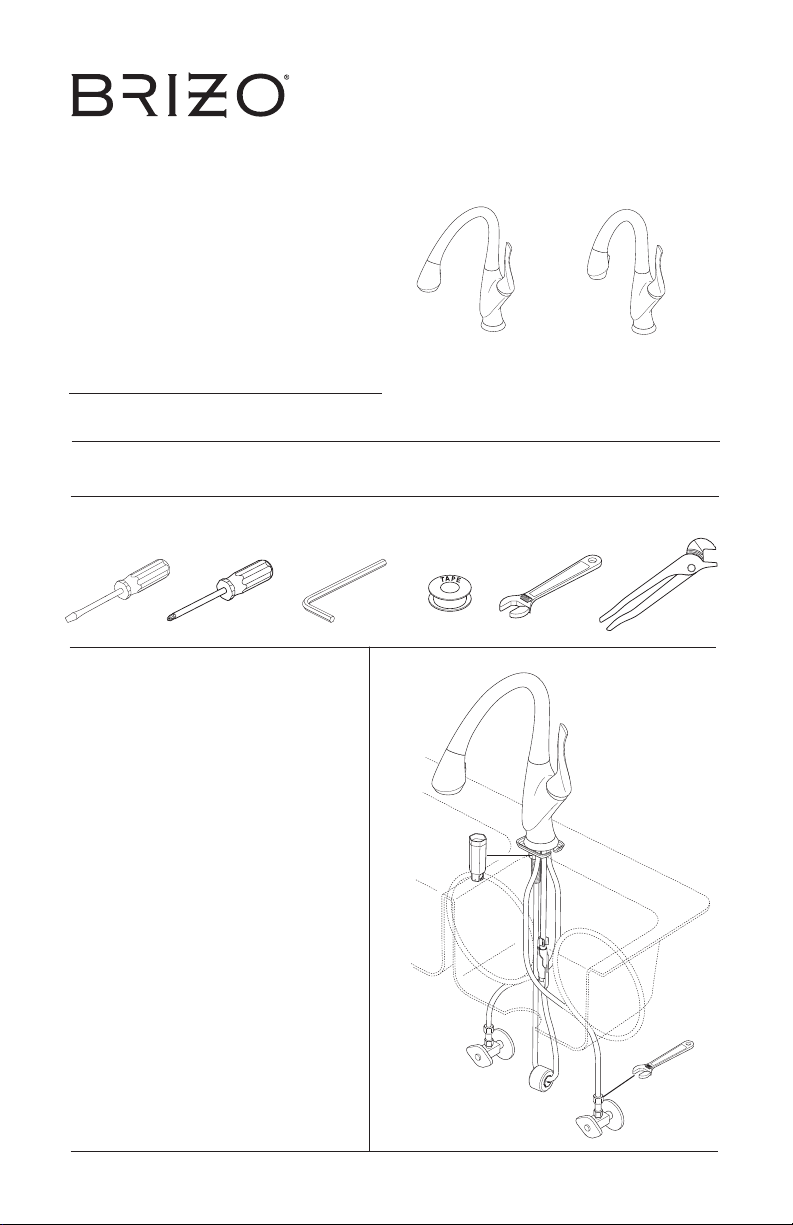
You may need the following tools:
1/8"
For easy installation of your Brizo®
faucet you will need:
• To READ ALL the instructions
completely before beginning.
• To READ ALL warnings, care, and
maintenance information.
77522 Rev. F
1
03/05/2018
Page 2

TABLE OF CONTENTS:
Warranty ------------------------------------------------------------- Page 2
Installation Instructions ----------------------------------------------- Pages 3-13
Plastic Sleeve Installation --------------------------------------------- Page 11
Setting The Handle Limit Stop ----------------------------------------- Page 14
Maintenance -------------------------------------------------------- Page 15
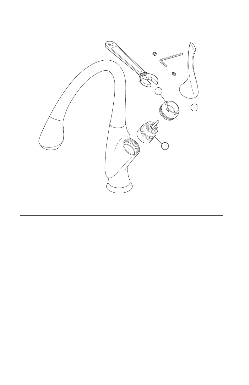
Replacement Parts -------------------------------------------------- Pages 16 & 17
Parts and Finish
All parts (other than electronic parts and batteries) and finishes of this Brizo
free from defects in material and workmanship for as long as the original consumer purchaser owns the home in which the faucet was first
installed or, for commercial users, for 5 years from the date of purchase.
Electronic Parts and Batteries (if applicable)
Electronic parts (other than batteries), if any, of this Brizo
material and workmanship for 5 years from the date of purchase or, for commercial users, for one year from the date of purchase. No warranty
is provided on batteries.
Brizo Kitchen & Bath Company will replace, FREE OF CHARGE, during the applicable warranty period, any part or finish that proves defective in material and/or workmanship under normal installation, use and service. If repair or replacement is not practical, Brizo Kitchen & Bath
Company may elect to refund the purchase price in exchange for the return of the product. These are your exclusive remedies.
Brizo Kitchen & Bath Company recommends using a professional plumber for all installation and repair. We also recommend that you use only
genuine Brizo
Brizo Kitchen & Bath Company shall not be liable for any damage to the faucet resulting from misuse, abuse, neglect or improper or incorrectly
performed installation, maintenance or repair, including failure to follow the applicable care and cleaning instructions.
Replacement parts may be obtained by calling the applicable number below or by writing to:
In the United States and Mexico: In Canada:
Brizo Kitchen & Bath Company Masco Canada Limited, Plumbing Group
Product Service Technical Service Centre
55 E. 111th Street 350 South Edgeware Road
Indianapolis, IN 46280 St. Thomas, Ontario, Canada N5P 4L1
1-877-345-BRIZO (2749) 1-877-345-BRIZO (2749)
brizosupport@brizo.com customerservice@mascocanada.com
Proof of purchase (original sales receipt) from the original purchaser must be made available to Brizo Kitchen & Bath Company for all warranty
claims unless the purchaser has registered the product with Brizo Kitchen & Bath Company. This warranty applies only to Brizo
factured after January 1, 1995 and installed in the United States of America, Canada and Mexico.
BRIZO KITCHEN & BATH COMPANY SHALL NOT BE LIABLE FOR ANY SPECIAL, INCIDENTAL OR CONSEQUENTIAL DAMAGES
(INCLUDING LABOR CHARGES) FOR BREACH OF ANY EXPRESS OR IMPLIED WARRANTY ON THE FAUCET. Some states/provinces do
not allow the exclusion or limitation of special, incidental or consequential damages, so these limitations and exclusions may not apply to you.
This warranty gives you special legal rights. You may also have other rights which vary from state/province to state/province.
This is Brizo Kitchen & Bath Company’s exclusive written warranty and the warranty is not transferable.
If you have any questions or concerns regarding our warranty, please view our Warranty FAQs at www.Brizo.com, email us at brizosupport@brizo.com
or call us at the applicable number above.
®
replacement parts.
Limited Warranty on Brizo
®
faucet are warranted to the original consumer purchaser to be free from defects in
®
Faucets
®
faucet are warranted to the original consumer purchaser to be
®
faucets manu-
© 2017 Masco Corporation of Indiana
77522 Rev. F
2
Page 3
1
A. C.
1
2
2
1
B.
Bend
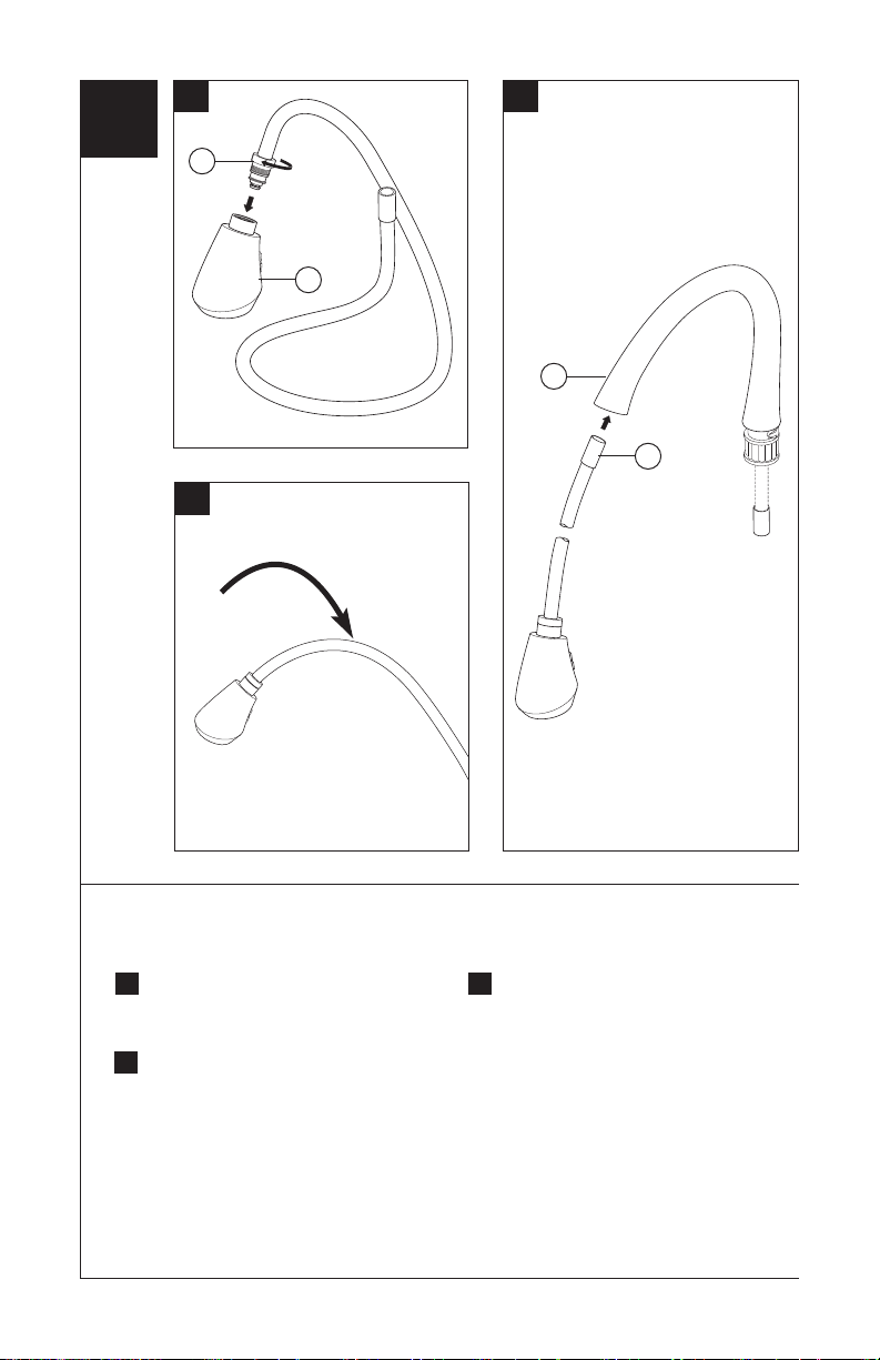
Hose Installation
Thread hose (1) into spray wand (2).
A.
To allow for easier assembly, bend
B.
hose near wand as shown.
77522 Rev. F
Insert hose (1) into and through spout
C.
sub-assembly (2).
3
Page 4
2
A.
1
2
3
77522 Rev. F
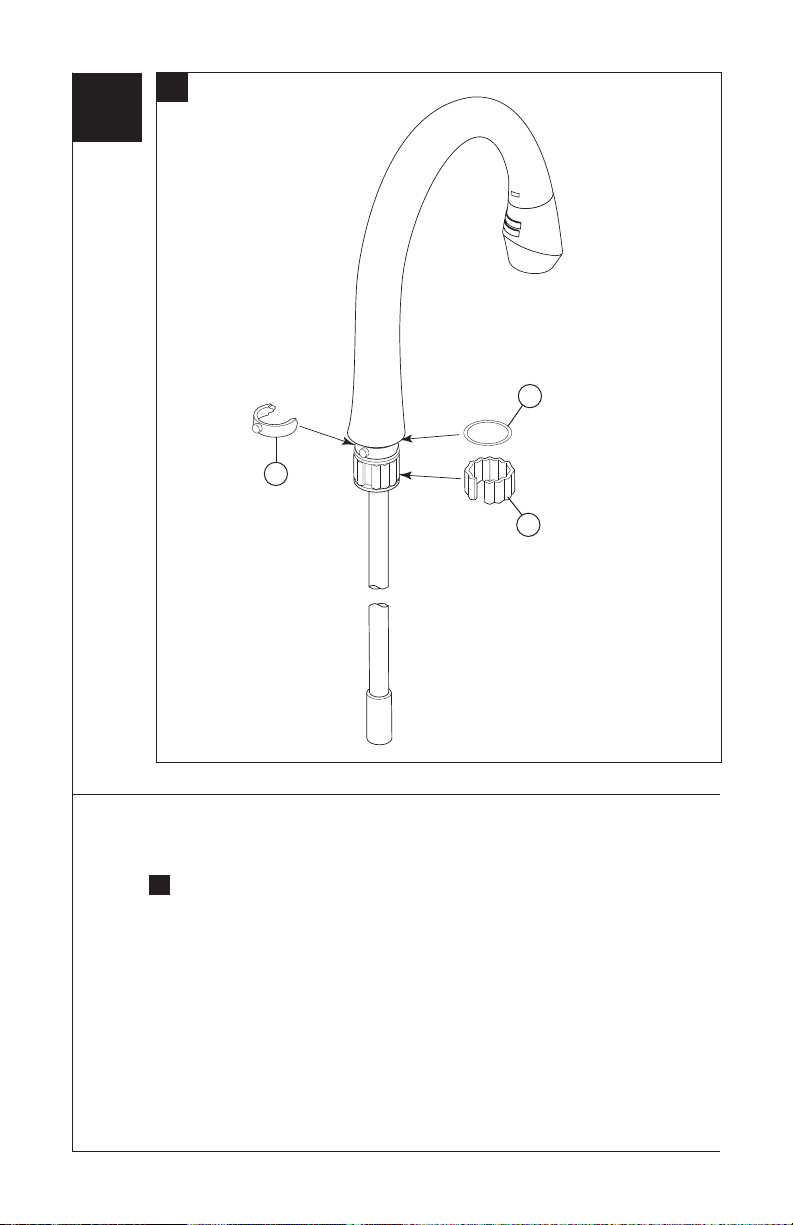
Spout Assembly
Verify friction washer (1), spout clip (2) and spout ring (3) are present on
A.
spout assembly.
4
Page 5
B.
C.
1
1
2
2
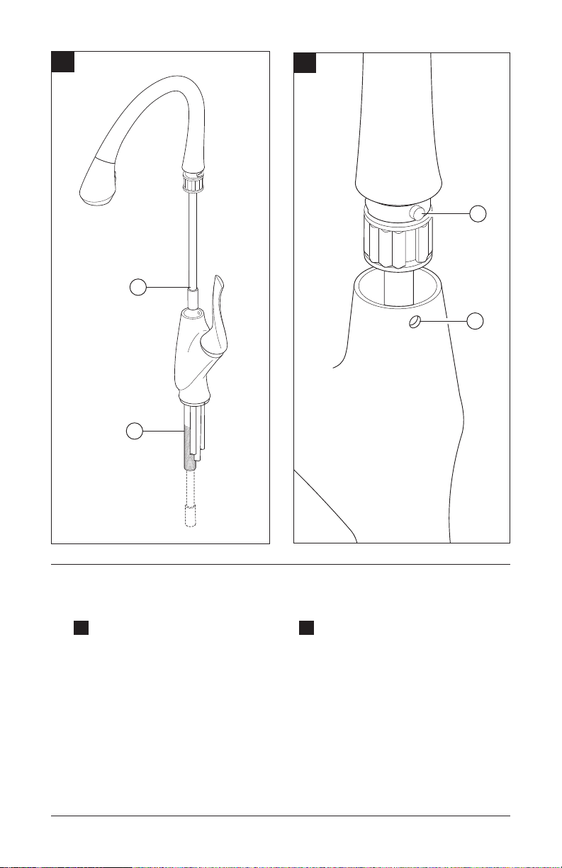
Spout Assembly (Continuation)
Insert hose (1) through guide in hub
B.
and out through mounting shank
(2).
77522 Rev. F
Align button (1) on spout clip with hole
C.
in hub (2), then insert spout into hub.
Use back-and-forth motion to insert
spout assembly into hub until clip
button slips into hole. Rotate spout
assembly to ensure smooth
operation. USE CAUTION NOT TO
PINCH FINGERS.
5
Page 6
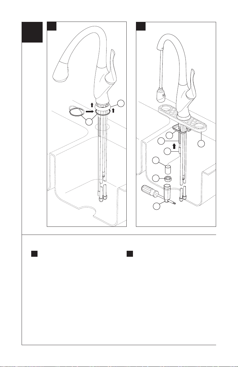
3
A. B.
2
1
3
2
1
6
4
7
Faucet Installation - Center Mount
Remove adhesive backing on trim
A.
ring gasket (1) and press into place
on trim ring (2). Place trim ring on
bottom of spout hub. Insert supply
tubes through mounting hole in sink.
Your faucet is designed for a hole
diameter of 1 3/8" +/- 1/4" (35 mm
+/- 6 mm) and a deck thickness of
up to 3" (76 mm). Maximum deck
thickness of soap dispenser is
3" (76 mm).
77522 Rev. F
6
5
Push hose (1) partially up into mounting
B.
shank (2). Install the mounting bracket
(3) and nut (4) onto the mounting shank
using wrench (5). For decks up to 1 3/8"
(35 mm) thick use spacer (6) provided
between nut and mounting bracket.
Note 1: The wrench provided is
designed to be used with a variety of
tools: flat/Phillips head screwdrivers,
wrenches, etc. Note 2: For thin
gauge sinks (not recommended), use
the thin deck aid (7) RP49588 (not
included) as shown for single and
3 hole installations to help support
the deck. HINT: Turn the spout tube
opposite the handle to balance the
assembly when mounting.
Page 7
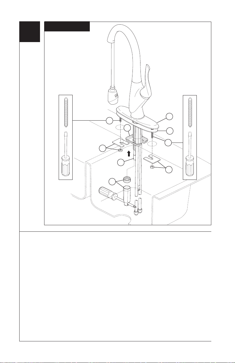
4
Optional
4
6
5
3
7
Optional Escutcheon Installation
For optional installations using the 10"
escutcheon, order RP49588 (specify finish)
not supplied. Replace the trim ring with the
10" escutcheon (1) and gasket (2). Push
hose (3) partially up into mounting shank.
Mount as shown above using the
two 1/4-20 studs (4), nuts and washers
(5), bracket (6) with nut and wrench (7).
The wrench provided is designed to
be used with a variety of tools:
flat/Phillips head screwdrivers,
wrenches, etc.
1
2
4
5
77522 Rev. F
7
Page 8
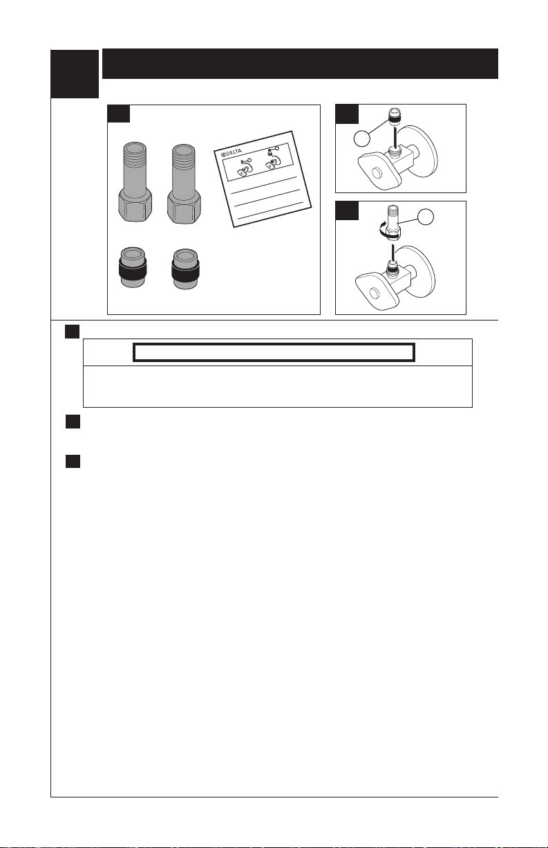
5
REQUIRED FOR MODEL 36052LF ONLY
A.
Important: To ensure proper operation of your plumbing it is essential to
install these check valve assemblies onto your supply stops.
1. Insert ferrule (1) into cold water stop.
2. Thread on check valve (2) and tighten (do not overtighten).
Continue instructions on page 2.
Importante: Para asegurar el funcionamiento debido de su plomería es esencial in-
stalar estos ensambles de válvulas checadoras en los topes del suministro de agua.
1. Introduzca el casquillo (1) en el tope del agua fría.
2. Enrosque la válvula de cheque (2) y apriete (no apriete demasiado).
Continúe las instrucciones en la página 2.
Important : Vous devez installer ces clapets de non-retour sur vos robinets
d’alimentation pour que la plomberie fonctionne correctement.
1. Introduisez la virole (1) dans le robinet d’alimentation en eau froide.
2. Vissez le clapet non-retour (2) et serrez-le (prenez garde de trop serrer).
Continuez les instructions à la page 2.
6/5/08
For this step, use the parts shown above.
A.
Check Valve Installation
Instalación de la Válvula Checadora
Installation du clapet de non-retour
1
2
53442 Rev B
1
B.
C.
1
2
Notice
Property damage and water leak possible. Incorrectly installed or unapproved check
valve assemblies may cause water leaks and property damage. Follow instructions to
install check valve assemblies provided with this faucet.
Important: To ensure proper operation of your plumbing it is essential to
B.
install these check valve assemblies onto your supply stops. Insert ferrule (1)
into cold water stop.
Thread on check valve (2) and tighten. DO NOT OVERTIGHTEN. Repeat steps B
C.
& C for hot water stop.
77522 Rev. F
8
Page 9
D.
1
4
2
3
4
2
3
OR
O
OU
E.
1
2
1
2
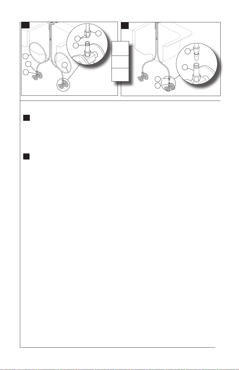
Water Line Connections
Ensure all fittings and end connections are free of debris. Faucet fittings (1) are 3/8"
D.
compression, with ends colored red for hot and blue for cold. Loop tubing (2) if it is too
long. Note: Recommended tubing minimum bend diameter is 8". Secure metal nut
(3) on faucet tube to check valve connection (4) and hand tighten, then tighten one
additional turn with wrench. DO NOT OVERTIGHTEN. Repeat for other tube. WARN-
ING: Do not use pipe dope or other sealants on water line connections.
Custom Fit Connections
E.
If you determine the PEX supply tubing for this faucet is too long and must be
shorter to create an acceptable installation, be sure to read the instructions and
plan ahead. When cutting the supply tubing the installer accepts the responsibility
to do so in a way that allows a leak-free joint to be created. Delta is not responsible
for tubing that is cut too short or cut in a way that will not allow for a leak-free joint.
For custom fit installations, you must use RP50952 sleeves supplied with model and nuts
included on supply lines. Tube cut must be straight. See plastic sleeve installation
instructions found in RP50952 and included in this document for more information.
Secure metal nut (1) on faucet tube to check valve connection (2) and hand tighten, then
tighten an additional 2 turns with wrench. DO NOT OVERTIGHTEN. Repeat for other
tube. WARNING: Do not use pipe dope or other sealants on water line connections.
Potential Problems and Remedies
● Tubing is not cut perpendicular to the axis of the tube: carefully make an additional cut,
being careful not to cut the tube too short.
● Tubing is cut too short: buy a coupling union and a replacement supply line that mate
together from a store. The coupling union end intended to connect to the faucet must mate
to the standard 3/8" connection nuts and plastic sleeves supplied with the faucet.
● The plastic sleeve or connection nut is lost: purchase a replacement nut and/or plastic
sleeve that are designed to seal with PEX tubing. NOTICE: DO NOT use a metal sleeve,
RP51243 gasket (supplied with faucet) or ferrule in the place of the plastic sleeve
supplied, it may not create a leak-free joint.
77522 Rev. F
9
Page 10
6
A.
3
1
2
2
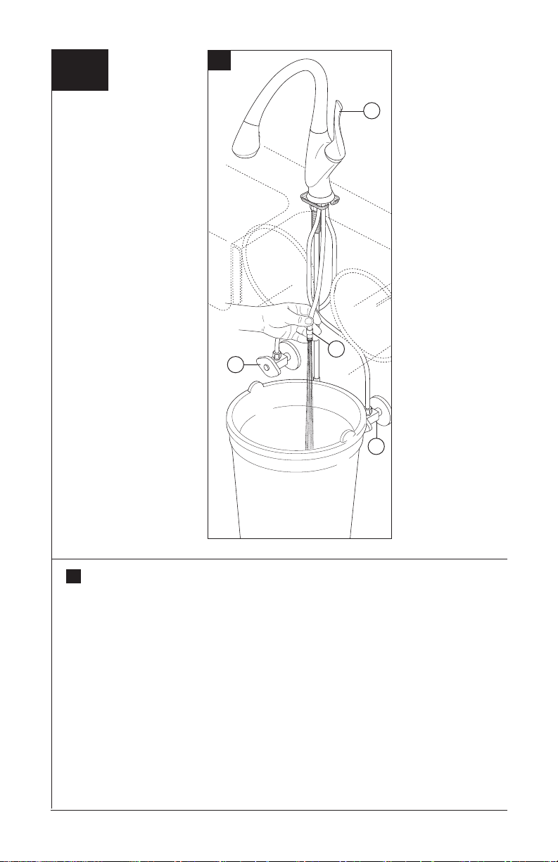
Place bucket under faucet quick connect fitting (1), open both supply valves (2) and
A.
turn faucet valve on by operating handle (3) for one minute. Important: This flushes
away any debris that could cause damage to internal components. When
complete, close both supply valves and turn faucet valve off to shut off water flow.
77522 Rev. F
10
Page 11
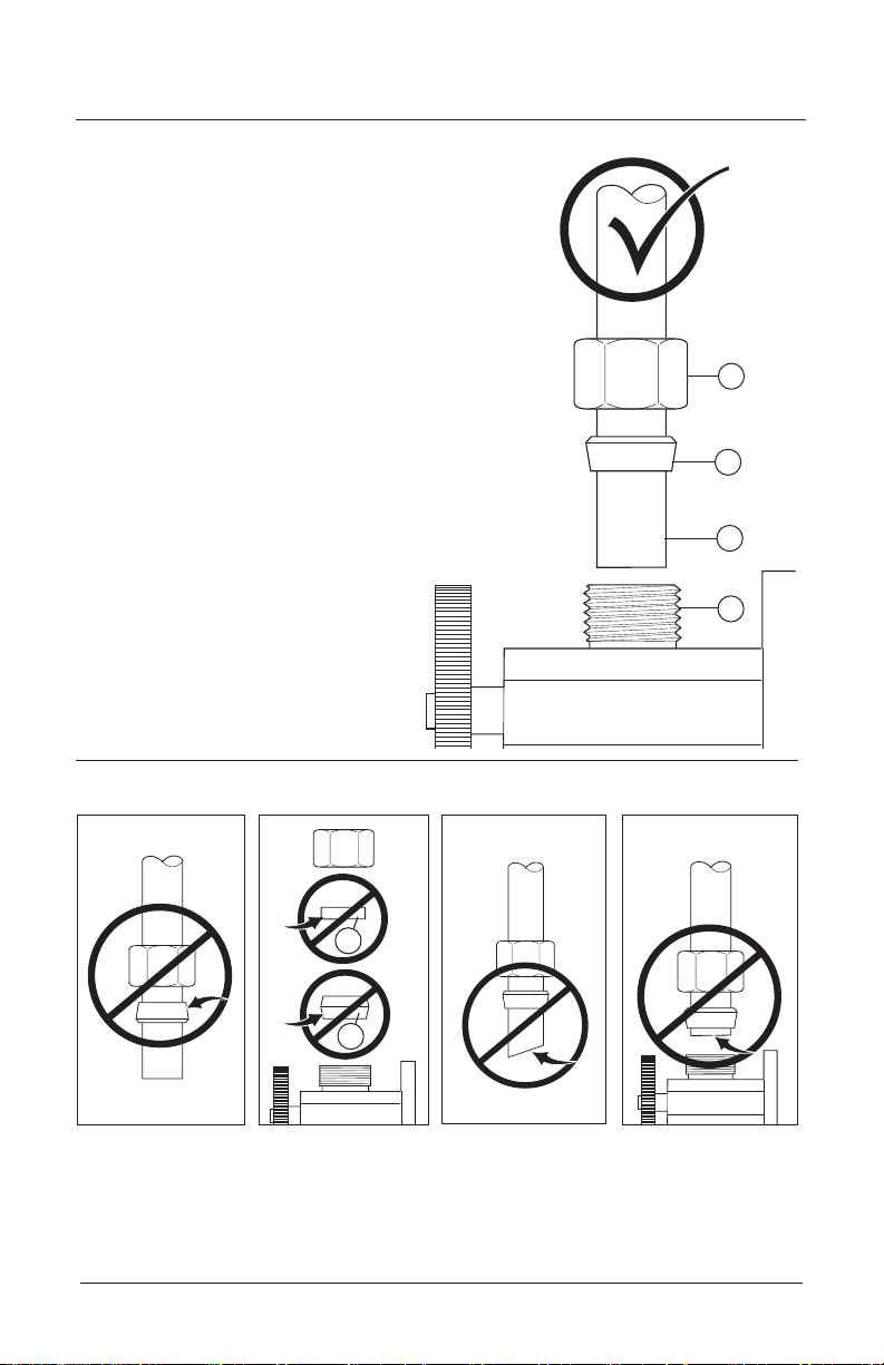
Custom Fit Connections - Plastic Sleeve Installation Instructions
Correct method
1. Identify desired length of tube (1). Leave 1" - 2"
of extra length to allow for easier installation and
cut tube. Ensure cut is straight and burr free.
2. Slide nut (2) and plastic sleeve (3) onto cut tube.
Ensure sleeve is oriented as shown.
3. Insert tube into outlet tting (4). Tube should
touch bottom of hole inside tting.
4. Slide plastic sleeve down tube until it engages
top of tting. WARNING: Failure to use plastic
sleeve in the correct orientation will result in
disconnection and possible water damage.
5. Slide nut over plastic sleeve. With wrench,
tighten nut 2 turns past nger tight.
2
3
1
4
Incorrect Installation
Do not install sleeve
upside down.
77522 Rev. F
Do not use RP51243
gasket (1) supplied
with PEX tubing or
brass ferrule (2)
supplied with
valve stops.
1
2
Ensure cut is straight.
Ensure tube is fully
inserted into stop
before sliding sleeve
down to engage top
of tting.
11
Page 12
7
A.
B.
C.
1
2
D.
1
D.
1
2
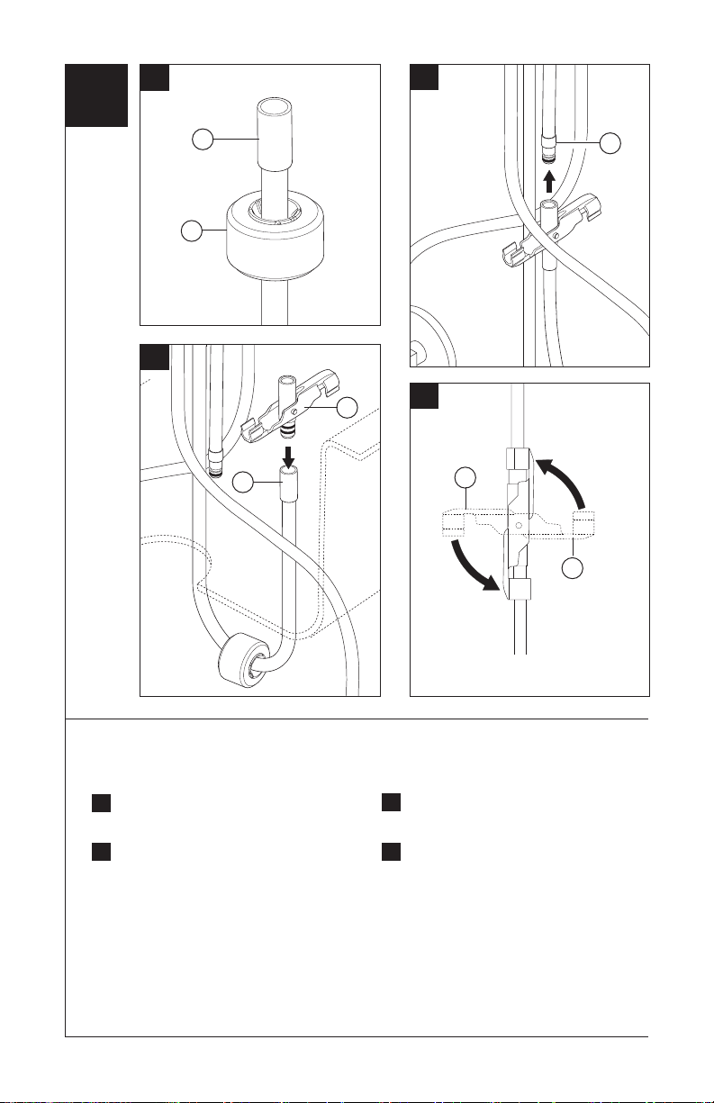
Sprayer Hose Connections
Insert hose end (1) through hose
A.
weight assembly (2).
Insert check-valve adapter (1) into
B.
pull-out hose fitting (2). Ensure
weight does not slide off hose.
1
1
Insert faucet outlet quick connect fitting
C.
(1) into adapter.
Rotate arms of adapter (1) to secure
D.
assembly to pull-out hose and faucet
outlet tube.
77522 Rev. F
12
Page 13
8
A.
B.
3
2
OR
Unlock
4
Lock
1
1
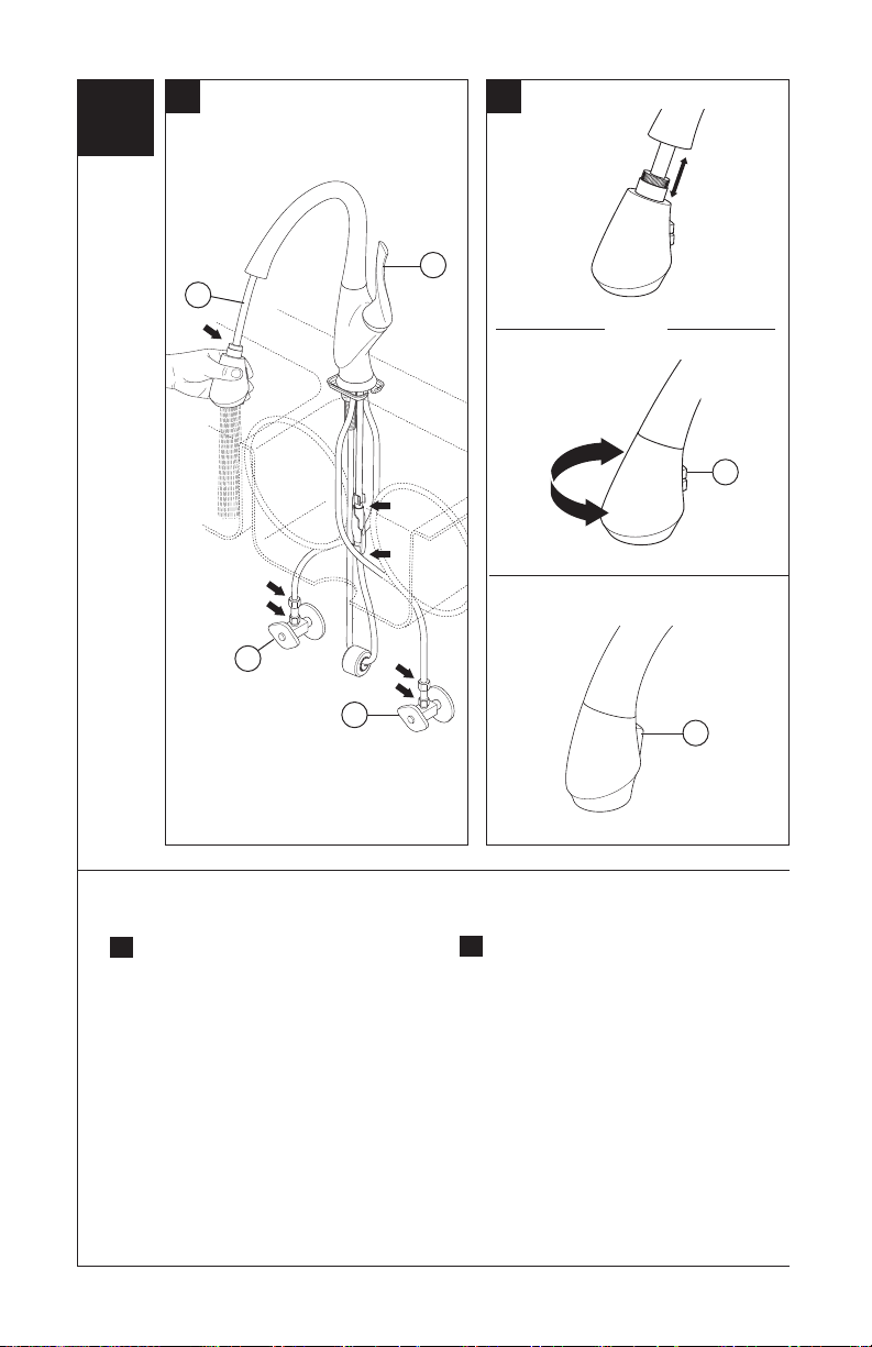
Faucet Inspection and Operation
Turn on hot and cold water supplies
A.
(1). Pull the hose assembly (2) out of
the spout. Be sure to hold the end of
the sprayer down into the sink and turn
faucet handle (3) to the mixed position
for one minute. Check all connections at
arrows for leaks. Re-tighten if necessary,
but do not overtighten.
77522 Rev. F
13
5
Sprayer will lock into position when
B.
brought into proximity of the spout
magnet. The sprayer can be removed
by either pulling directly out from the
spout or by twisting 90° in either
direction which will cause the magnets
to repel and the head to decouple from
the spout (recommended). Check the
operation of the sprayer by operating the
trigger (4) from aerator to spray. The
diverter will remain in the last diverted
mode. To reduce or pause ow, push
selector button further into wand. The
bar/prep faucet is a two function sprayer
only. Press button (5) to choose
between modes.
Page 14
9
1
Setting The Handle Limit Stop (Optional)
This faucet includes an integrated
handle limit stop that has two positions.
Position 1, to the left, allows full handle
motion (the full range between “all cold”
to “all hot”). The faucet is set in position
1 in the factory. Position 2, to the right,
allows half of the normal handle motion
(“all cold” to “mixed hot/cold”).
The handle limit stop can be adjusted
by the homeowner once the faucet is
installed. Setting the handle limit stop in
position 2 may help to prevent scalding
because it limits the amount of hot water
in the mix; however, this handle limit stop will
not always prevent scalding because it does
not compensate for incoming pressure or
sudden water temperature changes.
To change positions of the handle limit
stop: remove the handle; move the
valve stem to the all cold position so the
water is on; change the position of the
handle limit stop; turn off the water; reinstall
the handle.
2
77522 Rev. F
14
Page 15
T
E
F
L
O
N
2
1
3
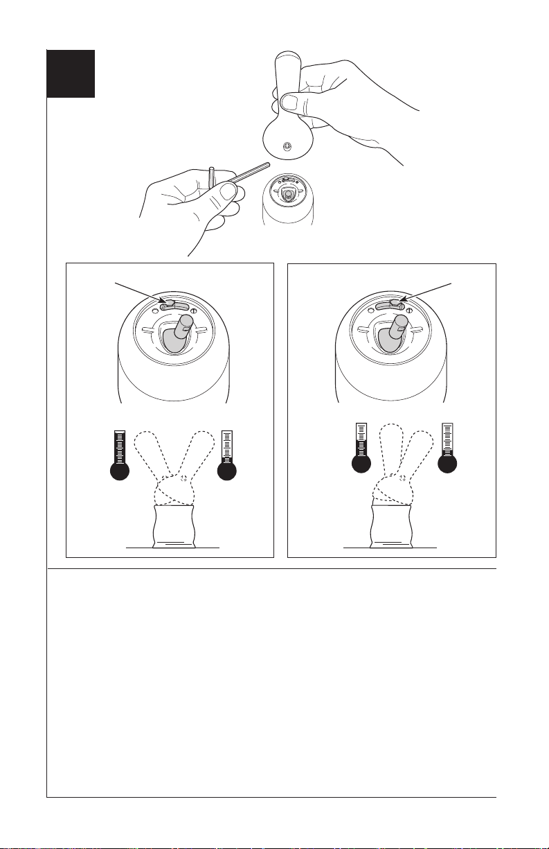
Maintenance
If faucet leaks from under handle:
Remove handle and ensure cap (1) is tight.
Use adjustable wrench on flats of cap (2) to
tighten cap.
If leak persists–SHUT OFF WATER
SUPPLIES. Replace valve cartridge (3).
If faucet leaks from spout outlet–SHUT
OFF WATER SUPPLIES. Replace valve
cartridge (3).
Cleaning And Care
Care should be given to the cleaning
of this product. Although its finish is
extremely durable, it can be damaged
by harsh abrasives or polish. To clean,
simply wipe gently with a damp cloth and
blot dry with a soft towel.
77522 Rev. F
Backow Protection System
Your Brizo® Faucet pull-down spout
incorporates a backow protection system
that has been tested to be in compliance
with ASME A112.18.3 and
ASME A112.18.1 / CSA B125.1. It
incorporates two certied check valves in
series, which operate independently.
Note: A small amount of water may run
out the spout or drip for a very short
period after the faucet is shut off. This is
a natural occurrence caused by the long
exible hose.
15
Page 16

77522 Rev. F
16
Page 17

LLAVES DE AGUA/GRIFOS
T
E
F
L
O
N
T
E
F
L
O
N
DE CAÑO EXTRAÍBLE
PARA COCINAS Y BARES /
MULTI-PROPÓSITO
BELO
®
Modelos
63052LF y 63952LF
Escriba aquí el número del modelo comprado.
ADVERTENCIA: ¡SESTA LLAVE NO SE DEBE UTILIZAR CON MAQUINAS
Para instalación fácil de su llave
Brizo® usted necesitará:
• LEER TODAS las instrucciones
completamente antes de empezar.
• LEER TODOS los avisos, cuidados, e
información de mantenimiento.
LAVAPLATOS PORTATILES!
Usted puede necesitar:
1/8"
77522 Rev. F
1
10/19/2017
Page 18

Índice:
Garantía ------------------------------------------------------------ Página 2
Instrucciones para la Instalación -------------------------------------- Páginas 3-14
Instalación de la Manga Plástica -------------------------------------- Página 11
Fijando la parada de límite de la manija -------------------------------- Página 14
Mantenimiento ------------------------------------------------------ Página 15
Piezas de Repuesto ------------------------------------------------- Páginas 16 y 17
Garantía Limitada de las llaves de agua/grifos Brizo
Piezas y Acabado
Todas las piezas (menos las piezas electrónicas y las pilas) y acabados de esta llave de agua - grifo Brizo® están garantizados al consumidor
comprador original, de estar libres de defectos en materiales y mano de obra durante el tiempo que el comprador original sea dueño de la
casa en la cual la llave de agua fue instalada por primera vez o, para los usuarios comerciales, por cinco (5) años desde la fecha de
compra.
Piezas electrónicas y las baterías/pilas (si aplicable)
Las piezas electrónicas (excepto las baterías), sea el caso, de este grifo Brizo® están garantizadas al consumidor comprador original, de estar
libres de defectos en materiales y mano de obra durante 5 años desde la fecha de compra o, para los usuarios comerciales, durante un año
desde la fecha de compra. La garantía no cubre las baterías.
Brizo Kitchen & Bath Company reparará o reemplazará, SIN COSTO ALGUNO, durante el período de garantía aplicable, cualquier pieza o
acabado que presente defectos en materiales y/o mano de obra bajo instalación, uso y servicio normal. Si la reparación o sustitución no es
práctica, Brizo Kitchen & Bath Company podrá optar reintegrarle el precio de la compra a cambio de la devolución del producto. Estos son
sus únicos recursos.
Brizo Kitchen & Bath Company recomienda que use un plomero profesional para todas las instalaciones y reparación. También recomienda
que utilice sólo piezas de repuesto Brizo®.
Brizo Kitchen & Bath Company no será responsable de cualquier daño a la llave de agua/grifo resultante del uso indebido, abuso, negligencia
o uso inapropiado o instalación realizada de forma incorrecta, mantenimiento o reparación, incluyendo el no seguir las instrucciones de cuidado y limpieza aplicables.
Las piezas de repuesto se pueden obtener llamando al número que figura más abajo o escribiendo a:
En los Estados Unidos y Mexico: En Canadá:
Brizo Kitchen & Bath Company Masco Canada Limited, Plumbing Group
Product Service Technical Service Centre
55 E. 111th Street 350 South Edgeware Road
Indianapolis, IN 46280 St. Thomas, Ontario, Canada N5P 4L1
1-877-345-BRIZO (2749) 1-877-345-BRIZO (2749)
brizosupport@brizo.com customerservice@mascocanada.com
La prueba de compra (recibo original de venta) del comprador original debe ponerse a la disposición de Brizo Kitchen & Bath Company para
todos los reclamos de garantía a menos que el comprador haya registrado el producto con Brizo Kitchen & Bath Company. Esta garantía
se aplica solamente a las llaves de agua/grifos Brizo® fabricadas después de 1 de enero de 1995 e instalados en los Estados Unidos de
América, Canadá y México.
BRIZO KITCHEN & BATH COMPANY NO SERÁ RESPONSABLE POR DAÑOS ESPECIALES, INCIDENTALES O CONSECUENTES
(INCLUYENDO CARGOS DE LABOR) YA SEAN RESULTANTES DEL INCUMPLIMIENTO DE CUALQUIER GARANTÍA EXPRESA O
IMPLÍCITA DE LA LLAVE DE AGUA/GRIFO. Algunos estados/provincias no permiten la exclusión o limitación de daños especiales, incidentales o consecuentes, por lo que estas limitaciones y exclusiones pueden no aplicarle en su caso.
Esta garantía le otorga derechos legales especiales, y usted también puede tener otros derechos que varían de estado/provincia a estado/
provincia.
Esta es la garantía exclusiva por escrito de Brizo Kitchen & Bath Company’s, y la garantía no es transferible.
Si usted tiene alguna pregunta o inquietud acerca de nuestra garantía, por favor vea nuestra sección de Preguntas Frecuentes sobre la garantía www.
Brizo.com, email us at brizosupport@brizo.com.
®
© 2017 Masco Corporación of Indiana
77522 Rev. F
2
Page 19

1
A. C.
1
2
2
1
B.
Doble
Instalación de la Manguera
Enrosque la manguera (1) en el
A.
mango del rociador (2).
Para permitir un ensamble más
B.
fácil,
doble la manguera cerca del mango
como se muestra.
77522 Rev. F
Introduzca la manguera (1) en y a
C.
través del sub-ensamble del
surtidor (2).
3
Page 20

2
A.
1
2
3
Ensamble de Surtidor
Verique si la arandela de fricción (1), gancho del surtidor (2) y el aro del surtidor
A.
(3), están presentes en el ensamble del surtidor.
77522 Rev. F
4
Page 21

B.
C.
1
1
2
2
Ensamble de Surtidor (Continuación)
Introduzca la manguera (1) por la
B.
guía en el cuerpo y hacia fuera por
la espiga de instalación (2).
77522 Rev. F
C.
5
Alinee el botón (1) en el gancho del
surtidor con el agujero en el cuerpo
(2), luego introduzca el surtidor en
el cuerpo. Use un movimiento de
vaivén para introducir el ensamble
del surtidor en el cuerpo hasta que el
botón del gancho quede introducido
en el agujero. Gire el ensamble del
surtidor para asegurar un funcionamiento suave. USE CAUTELA PARA
NO PELLIZCARSE LOS DEDOS.
Page 22

3
A. B.
2
1
3
2
1
6
4
7
5
Instalación de la Llave de Agua – Instalación de Centro
Quite el adhesivo al dorso del
A.
empaque del aro de accesorio (1)
y oprima en su sitio en el aro de
accesorio (2). Coloque el aro de
accesorio en el fondo del cuerpo del
surtidor. Introduzca las tuberías de
suministro de agua a través del orificio para la instalación del fregadero.
Su llave de agua está diseñada para
un orificio de 1 3/8” +/- 1/4” (35 mm
+/- 6 mm) de diámetro y un grosor
de la encimera de 3” (76 mm). El
grosor máximo de las encimeras
para los dispensadores de jabón es
3” (76 mm).
77522 Rev. F
Deje pasar la manguera (1) parcialmente
B.
hacia arriba en la espiga de instalación (2).
Instale el soporte de la instalación (3) y la
tuerca (4) en la espiga de instalación usando
la llave de tuercas (5). Para encimeras
de un grosor hasta 1 3/8” (35 mm) use
un separador (6) incluido, entre la tuerca
y el soporte de instalación. Nota 1: La
llave de tuercas incluida está diseñada
para usarse con una variedad de
herramientas: destornilladores de cabeza
plana/Phillips, llaves de tuercas, etc.
Nota 2: Para fregaderos delgados (no se
recomienda), use el refuerzo (7) RP49588
(no incluido) para soporte de la encimera
como se muestra para instalación
sencilla y de 3 orificios. SUGERENCIA:
Cuando haga la instalación gire el caño del
surtidor en dirección opuesta a la manija
para balancear el ensamble.
6
Page 23

4
Opcional
4
6
5
3
7
Instalación de una Chapa Opcional
Para instalaciones opcionales usando la
chapa o chapetón de 10”, ordene la pieza
RP49588 (especifique el acabado) no se
incluye. Reemplace el aro de accesorio
por la chapa de 10” (1) y el empaque (2).
Pase la manguera (3) parcialmente hacia
arriba por la espiga de instalación.
Instale como se muestra arriba usando los
pernos de 2 1/4-20 (4), las tuercas y
arandelas (5), el soporte (6) con la
tuerca y la llave de tuercas (7). La llave
de tuercas incluida está diseñada
para usarse con una variedad de
herramientas: destornilladores de
cabeza plana/Phillips, llaves de
tuercas, etc.
1
2
4
5
77522 Rev. F
7
Page 24

NECESARIO SÓLO PARA EL MODELO 36052LF
5
A.
B.
A.
Check Valve Installation
Instalación de la Válvula Checadora
2
Installation du clapet de non-retour
1
Important: To ensure proper operation of your plumbing it is essential to
install these check valve assemblies onto your supply stops.
1. Insert ferrule (1) into cold water stop.
2. Thread on check valve (2) and tighten (do not overtighten).
Continue instructions on page 2.
Importante: Para asegurar el funcionamiento debido de su plomería es esencial instalar estos ensambles de válvulas checadoras en los topes del suministro de agua.
1. Introduzca el casquillo (1) en el tope del agua fría.
2. Enrosque la válvula de cheque (2) y apriete (no apriete demasiado).
Continúe las instrucciones en la página 2.
Important : Vous devez installer ces clapets de non-retour sur vos robinets
d’alimentation pour que la plomberie fonctionne correctement.
1
1. Introduisez la virole (1) dans le robinet d’alimentation en eau froide.
2. Vissez le clapet non-retour (2) et serrez-le (prenez garde de trop serrer).
Continuez les instructions à la page 2.
6/5/08
53442 Rev B
B.
C.
1
2
Para este paso, utilice las piezas mostradas anteriormente.
Aviso
Es posible que se produzcan daños a la propiedad y fugas o ltraciones de agua. El
ensamble de la llave de paso incorrectamente instalado o no aprobado puede causar
fugas de agua y daños a la propiedad. Siga las instrucciones para instalar el ensamble
de la llave de paso provisto con esta llave de agua.
Importante: Para asegurar el funcionamiento correcto de su plomería es esen-
cial instalar los ensambles de las válvulas checadoras en los topes del suministro. Introduzca el casquillo (1) en el pare de agua fría.
Enrosque en el adaptador (2) y apriete. NO APRIETE DEMASIADO. Repita los
C.
pasos B y C en el tope del agua caliente.
77522 Rev. F
8
Page 25

D.
1
4
2
3
4
2
3
OR
O
OU
E.
1
2
1
2
Conexiones a la Línea de Agua
Asegúrese que todos los accesorios y las conexiones finales estén libres de residuos.
D.
Los accesorios (1) son de compresión de 3/8”, con los extremos de color rojo para el
agua caliente y azul para el agua fría. Enlace las tuberías (2) si es muy larga. Nota: La
curva mínima recomendada es de 8" de diámetro. Fije la tuerca de metal (3) en el
tubo de la llave de agua a la conexión (4) y apriete a mano, luego apriete con una vuelta
adicional con una llave de tuercas. NO APRIETE DEMASIADO. Repita con el otro tubo.
AVISO: No use compuesto para tuberías u otros selladores en las conexiones
de la tubería de agua.
Conexiones Especiales
E.
AVISO: Si usted determina que la tubería PEX para el suministro de agua para esta
llave de agua es muy larga y debe recortarse para crear una instalación aceptable,
asegúrese leer las instrucciones y planifique de antemano. Cuando corte la tubería de
suministro el instalador acepta la responsabilidad de hacerlo de una manera que
permite crear una articulación sin filtraciones. Delta no se responsabiliza por las tuberías que se han cortado demasiado cortas o cortadas de una manera que no permite
una articulación libre
de filtración.
Para instalaciones hechas a la medida, usted debe usar mangas RP50952 incluidas con el
modelo y las tuercas incluidas en las tuberías de suministro. El corte del tubo debe ser recto.
Vea las instrucciones para la instalación de la manga plástica incluida con el RP50952 y para
más información incluida en este documento.
Fije la tuerca de metal (1) en la tubería de la llave de agua / grifo a la conexión de la válvula de
suministro (2) y apriete a mano. Con la llave de tuercas, apriete la tuerca dándole 2 vueltas más
de si fuera apretado a mano. NO APRIETE DEMASIADO. Repita con la otra tubería. AVISO: No
use compuesto para tuberías u otros selladores en las conexiones de la tubería de agua.
Problemas Potenciales y Soluciones
● La tubería no está cortada perpendicular al eje del tubo: cuidadosamente haga un corte
adicional, teniendo cuidado de no cortar el tubo demasiado corto.
● La tubería está cortada demasiado corta: compre en un almacén un acoplamiento de unión y
una tubería de suministro de repuesto que acoplen. El extremo de la unión de acoplamiento que
es para conectar a la llave de agua debe acoplar con las tuercas estándares de 3/8" y mangas de
plástico incluidas con la llave de agua / grifo.
● La manga plástica o la tuerca de conexión se ha perdido: compre una tuerca de repuesto
y/o manga plástica diseñada para sellar con la tubería PEX. AVISO: No use una manga de
metal, RP51243 empaque (suministrado con el grifo) o casquillo, en vez de la manga
incluida puede no crear una articulación sin filtración.
77522 Rev. F
9
Page 26

6
A.
3
1
2
2
Coloque un cubo por debajo de la conexión rápida de la llave de agua (1) y abra
A.
por un minuto ambas válvulas (2) y manija (3) de suministro de agua. Importante:
Esto limpia cualquier residuo que pudiera causar daño a los componentes
internos. Cuando termine cierre ambas válvulas y manija de suministro de agua.
77522 Rev. F
10
Page 27

Instrucciones para la Instalación del la Manga Plástica
Método Correcto
1. Identique la longitud deseada del tubo (1). Deje
1” – 2” de soltura para una instalación más fácil y
sin rebabas. Asegure que el corte sea recto y
sin rebabas.
2. Resbale la tuerca (2) y la manga plástica (3)
sobre el tubo cortado. Asegure la manga se
orienta según lo demostrado.
3. Introduzca el tubo dentro del accesorio (4). El
tubo debe tocar el fondo del agujero dentro
del accesorio.
4. Deslice la manga plástica hacia abajo en el
tubo hasta que encaje el la parte superior
del accesorio. AVISO: El no usar la manga
plástica en la orientación correcta resultará
en desconexión y posible daño por agua.
5. Deslice la tuerca sobre la manga plástica. Con
la llave de tuercas, apriete la tuerca dándole 2
vueltas más de si fuera apretado a mano.
2
3
1
4
Instalación Incorrecta
No instale la manga
boca abajo.
77522 Rev. F
No use RP51243
empaque (1)
suministrado con el
tubería de PEX o el
casquillo de bronce
(2) suministrado con
las válvulas de cierre.
1
2
Asegúrese que el
corte esté recto.
Asegúrese que el
tubo este completamente introducido
dentro del tope antes
de deslizar la manga
hacia abajo para encajar la parte superior
del accesorio.
11
Page 28

7
A.
B.
C.
1
2
D.
1
D.
1
2
1
Conexiones de la Manguera con Rociador
Introduzca el extreme de la manguera
A.
(1) por el ensamble de la pesa de la
manguera (2).
Introduzca el adaptador de la válvula
B.
de retención (1) en el accesorio
extraíble de la manguera (2).
Asegúrese que la pesa no se deslice
de la manguera.
Introduzca el empalme de conexión
C.
rápida en el extremo de salida de agua
del grifo (1) en el adaptador.
Gire el adaptador (1) para fijar el
D.
ensamble a la manguera extraíble y el
tubo de salida de la llave de agua.
1
77522 Rev. F
12
Page 29

8
A.
B.
3
2
o
abrir
4
cerrar
1
1
5
Inspección de la Llave de Agua / Grifo y Funcionamiento
Abra los suministros de agua caliente y
A.
fría (1). Hale la manguera extraíble (2)
del surtidor. Asegúrese de sujetar el
extremo de rociador hacia el fregadero y
abra la llave de agua con la manija (3) a
la posición mixta por un minuto.
Examine todas las conexiones en los
puntos señalados con flechas donde
pudiera haber filtraciones. Apriete
de nuevo si es necesario, pero no
apriete demasiado.
77522 Rev. F
El rociador quedará jo en su posición
B.
cuando se acerca al imán del surtidor.
El rociador puede sacarse halándolo
directamente hacia fuera del surtidor o
girándolo 90° en cualquier dirección que
hará que los imanes se repelen y la
cabeza de desconecte del surtidor (se
recomienda). Examine el funcionamiento del rociador al operar el gatillo (4) del
aireador al rociador. El desviador
permanecerá en el último modo que
usó. Para reducir o parar el ujo, oprima
el botón de selección más adentro en el
mango. La llave de agua para bares /
multi-propósito es de sólo dos funciones
de rocío. Oprima el botón (5) para
escoger entre los modos.
13
Page 30

9
1
Fijando la parada de límite de la manija (opcional)
Esta llave de agua incluye una manija
integrada, que tiene dos posiciones, para
limitar la temperatura. La posición 1, a la
izquierda, permite el movimiento completo
de la manija (el alcance completo entre el
agua “totalmente fría” hasta “totalmente
caliente”). La fábrica preselecciona la
llave de agua (grifo) a la posición 1. La
posición 2, a la derecha, permite la mitad
del alcance de movimiento normal de la
manija (“totalmente fría” a la posición “mixta
caliente/fría”).
Una vez que la llave de agua (grifo) se
ha instalado, el límite rotacional de la
manija puede ajustarse por el propietario
de la residencia. Ajustando la manija de
ajuste del tope del límite de la temperatura
a la posición 2 puede ayudar a prevenir
escaldaduras porque limita la cantidad de
agua caliente en la mezcla; sin embargo,
esta manija que limita la temperatura del
agua no siempre prevendrá escaldaduras
porque no compensa la presión del agua
de entrada o cambios repentinos de la
temperatura del agua.
Para cambiar las posiciones de la manija
que limitan la temperatura: quite la
manija; cambie la posición de la espiga de
la válvula a la posición totalmente fría de
manera que el agua este abierta; cambie la
posición de la manija que limita la temperatura; cierre el agua; reinstale la manija.
2
77522 Rev. F
14
Page 31

T
E
F
L
O
N
2
1
3
Mantenimiento
Si el grifo se escapa de debajo la manija:
Quite la manija y asegúrese que el casquillo
(1) es apretado.
Utilice la llave ajustable en planos del casquillo
(2) para apretar el casquillo.
Si la filtración persiste – CIERRE LOS
SUMINISTROS DE AGUA. Cambie el cartucho
de la válvula (3).
Si la llave de agua tiene una filtración
desde la salida del surtidor – CIERRE LOS
SUMINISTROS DE AGUA. Cambie el cartucho
de la válvula (3).
Limpieza Y Cuidado
De Su Llave
Tenga cuidado al ir a limpiar este producto.
Aunque su acabado es sumamente durable,
puede ser afectado por agentes de limpieza
o para pulir abrasivos. Para limpiar su llave,
simplemente frótela con un trapo húmedo y
luego séquela con una toalla suave.
77522 Rev. F
Sistema de protección
contra el contraujo
Su llave de agua tipo deslizable Delta tiene
un sistema de protección contra el
contraujo, incorporado, que ha sido
probado para cumplir con los requisitos de
ASME A112.18.3 y ASME A112.18.1 /
CSA B125.1. Este incorpora en la pieza
de mano dos válvulas de retención o
checadoras certicadas en una serie, las
cuales operan independientemente
Nota: Una cantidad pequeña de agua
puede escurrirse del surtidor o gotear
por un período corto de tiempo después
de cerrar el agua. Esto es una ocurrencia
natural causada por la manguera
larga exible.
15
Page 32

77522 Rev. F
16
Page 33

ROBINETS D’ÉVIER DE BAR ET
T
E
F
L
O
N
T
E
F
L
O
N
D’ÎLOT À BEC RÉTRACTABLE
BELO
®
Modèles
63052LF & 63952LF
Inscrivez le numéro de modèle ici.
MISE EN GARDE : NE PAS RACCORDER DE LAVE-VAISSELLE MOBILES À CE ROBINET!
Articles dont vous pouvez avoir besoin:
1/8 po
Pour installer votre robinet
Brizo® facilement, vous devez:
• LIRE TOUTES les instructions avant
de débuter;
• LIRE TOUS les avertissements ainsi
que toutes les instructions de
nettoyage et d’entretien;
77522 Rev. F
1
10/19/2017
Page 34

TABLE DES MATIÈRES
Garantie -------------------------------------------------------------- Page 2
Instructions d’installation ----------------------------------------------- Pages 3-14
Installation du manchon de plastique ------------------------------------- Page 11
Plaçant l’arrêt de limite de poignée ------------------- ------------------- Page 14
Maintenance ---------------------------------------------------- ------ Page 15
Pièces de rechange --------------------------------------------------- Pages 16 e t 17
Pièces et finis
Toutes les pièces et tous les finis de ce robinet Brizo® sont protégés contre les défectuosités du matériau et les vices de fabrication par
une garantie qui est consentie au premier acheteur et qui demeure valide tant que celui-ci demeure propriétaire de la maison dans laquelle
l’accessoire a été installé. Dans le cas d’une utilisation commerciale, la garantie est de 5 ans à compter de la date d’achat.
Composants électroniques et piles (le cas échéant)
Si ce robinet Brizo® comporte des composants électroniques, ces composants (à l’exception des piles) sont protégés contre les défectuosités du matériau et les vices de fabrication par une garantie consentie au premier acheteur qui est d’une durée de 5 ans à compter de la date
d’achat. Dans le cas d’une utilisation commerciale, la garantie est d’un an à compter de la date d’achat. Aucune garantie ne couvre les piles.
Pendant la période de garantie applicable, Brizo Kitchen & Bath Company réparera ou remplacera GRATUITEMENT toute pièce qui présentera une défectuosité de matériau et/ou un vice de fabrication pour autant que le produit ait été installé, utilisé et entretenu normalement.
S’il est impossible de réparer ou de remplacer le produit, Brizo Kitchen & Bath Company pourra rembourser le prix d’achat en échange du
produit retourné. Il s’agit de vos seuls recours.
Brizo Kitchen & Bath Company recommande de confier l’installation et la réparation à un plombier professionnel. Nous vous recommandons
également d’utiliser uniquement des pièces de rechange d’origine Brizo®.
Brizo Kitchen & Bath Company se dégage de toute responsabilité à l’égard de toute détérioration du produit résultant d’une usure raisonnable et des dommages causés par un mauvais usage, un usage abusif, la négligence ou l’utilisation d’une méthode d’installation, de
maintenance ou de réparation incorrecte ou inadéquate, y compris les dommages résultant du non-respect des instructions de nettoyage et
d’entretien applicables.
Vous pouvez obtenir des pièces de rechange en appelant au numéro de téléphone ci-dessous ou en écrivant à:
Aux États-Unis et au Mexique: Au Canada:
Brizo Kitchen & Bath Company Masco Canada Limited, Groupe plomberie
Product Service Centre de services techniques
55 E. 111th Street 350 South Edgeware Road
Indianapolis, IN 46280 St. Thomas, Ontario, Canada N5P 4L1
1-877-345-BRIZO (2749) 1-877-345-BRIZO (2749)
brizosupport@brizo.com customerservice@mascocanada.com
La preuve d’achat (reçu original) du premier acheteur doit être présentée à Brizo Kitchen & Bath Company pour toutes les demandes en
vertu de la garantie, sauf si le produit a été enregistré auprès de Brizo Kitchen & Bath Company. La présente garantie s’applique uniquement
aux accessoires Brizo® installés aux États-Unis d’Amérique, au Canada et au Mexique.
BRIZO KITCHEN & BATH COMPANY SE DÉGAGE DE TOUTE RESPONSABILITÉ À L’ÉGARD DES DOMMAGES PARTICULIERS,
CONSÉCUTIFS ET INDIRECTS (Y COMPRIS LES FRAIS DE MAIN-D’ŒUVRE ) QUI DÉCOULENT D’UNE RUPTURE D’UNE GARANTIE
IMPLICITE OU EXPLICITE DU ROBINET. Dans les États ou les provinces où il est interdit d’exclure ou de limiter les dommages particuliers,
consécutifs ou indirects, les exclusions ou les limites susmentionnées ne s’appliquent pas. La présente garantie vous procure des droits particuliers reconnus par la loi. Vous pouvez avoir d’autres droits qui varient selon l’État ou la province.
La présente garantie écrite est la seule garantie offerte par Brizo Kitchen & Bath Company et elle n’est pas transférable.
Si vous avez des questions ou des préoccupations en ce qui concerne notre garantie, veuillez consulter la page Warranty FAQs à www.Brizo.com,
nous faire parvenir un courriel à brizosupport@brizo.com ou nous appeler au numéro applicable.
Garantie limitée sur les robinets Brizo
®
© 2017 Division de Masco Indiana
77522 Rev. F
2
Page 35

1
A. C.
1
2
2
1
B.
courbez
Installation du exible
Vissez le exible (1) dans la
A.
poignée du bec-douchette (2).
Pour faciliter l’installation, courbez
B.
le exible près de la poignée
comme le montre la gure.
77522 Rev. F
Introduisez le exible (1) dans le bec
C.
et faites-le glisser de part en part du
bec (2).
3
Page 36

2
A.
1
2
3
Installation du bec
Assurez-vous que la rondelle de frottement (1), l’agrafe du bec (2) et l’anneau du
A.
bec (3) se trouvent sur le bec.
77522 Rev. F
4
Page 37

B.
C.
1
1
2
2
Installation du bec (suite)
Introduisez le exible (1) dans le
B.
guide du porte-bec, puis dans la
tige de montage (2).
77522 Rev. F
Faites correspondre le bouton (1)
C.
sur l’agrafe du bec avec le trou dans
le porte-bec (2), puis introduisez le
bec dans le porte-bec. Imprimez un
mouvement de va-et-vient au bec
pour l’introduire dans le porte-bec
jusqu’à ce que le bouton de l’agrafe
pénètre dans le trou. Faites pivoter le
bec pour vous assurer qu’il pivote en
douceur. PRENEZ GARDE DE VOUS
PINCER LES DOIGTS.
5
Page 38

3
A. B.
2
1
3
2
1
6
4
7
Installation du robinet –
Montage dan le trou au centre de l’évier
Enlevez l’endos adhésif sur le joint
A.
circulaire (1) et placez-le contre
l’anneau de finition (2). Exercez une
pression sur le joint. Placez l’anneau
de finition contre le dessous du
porte-bec. Introduisez les tubes
d’alimentation dans le trou de montage de l’évier. Le robinet est conçu
pour un trou d’un diamètre de 1 3/8
± 1/4 po (35 mm ± 6 mm) et pour un
comptoir d’une épaisseur maximale
de 3 po (76 mm). L’épaisseur maximale admissible pour le distributeur
de savon est de 3 po (76 mm).
77522 Rev. F
Introduisez le flexible (1) partiellement
B.
dans la tige de montage (2). Installez
le support (3) et l’écrou (4) sur la tige
de montage à l’aide de la clé (5). Si le
comptoir a 1 3/8 po (35 mm) d’épaisseur
ou moins, placez la cale (6) fournie entre
l’écrou et le support de montage.
Note 1 : La clé fournie est conçue
pour être utilisée avec une variété
d’outils : tournevis à extrémité plate
ou Phillips, clés, etc. Note 2 : Si
l’évier est mince (non recommandé),
supportez le comptoir avec la plaque
de renfort (7) RP49588 (non inclus),
comme le montre la figure, qu’il
s’agisse d’une installation dans un ou
trois trous. Conseil : Placez le bec du
côté opposé à celui de la manette pour
équilibrer le robinet pendant le montage.
6
5
Page 39

4
Facultative
4
6
5
3
7
1
2
4
5
Installation de la plaque de nition facultative
Pour une installation nécessitant la plaque
de finition facultative de 10 po, commandez le kit RP49588 (précisez le fini) non
fourni. Remplacez l’anneau de finition par
la plaque de finition de 10 pouces (1) et le
joint (2). Poussez le flexible (3) partiellement vers le haut dans la tige de montage.
Montez la plaque comme le montre la figure ci-dessus à l’aide des goujons
2 1/4 - 20 (4), des écrous et des rondelles
(5) et du support (6) avec l’écrou et la
clé (7). La clé fournie est conçue pour
être utilisée avec une variété d’outils :
tournevis à extrémité plate ou Phillips,
clés, etc.
77522 Rev. F
7
Page 40

REQUIS UNIQUEMENT POUR LE MODÈLE 36052LF
5
A.
Check Valve Installation
Instalación de la Válvula Checadora
2
Installation du clapet de non-retour
1
Important: To ensure proper operation of your plumbing it is essential to
install these check valve assemblies onto your supply stops.
1. Insert ferrule (1) into cold water stop.
2. Thread on check valve (2) and tighten (do not overtighten).
Continue instructions on page 2.
Importante: Para asegurar el funcionamiento debido de su plomería es esencial in-
stalar estos ensambles de válvulas checadoras en los topes del suministro de agua.
1. Introduzca el casquillo (1) en el tope del agua fría.
2. Enrosque la válvula de cheque (2) y apriete (no apriete demasiado).
Continúe las instrucciones en la página 2.
Important : Vous devez installer ces clapets de non-retour sur vos robinets
d’alimentation pour que la plomberie fonctionne correctement.
1. Introduisez la virole (1) dans le robinet d’alimentation en eau froide.
2. Vissez le clapet non-retour (2) et serrez-le (prenez garde de trop serrer).
Continuez les instructions à la page 2.
6/5/08
Pour cette étape, veuillez utiliser le sac qui porte le chiffre.
A.
Possibilité de dommages matériels et de fuite. Une mauvaise installation des
clapets de non-retour ou l’installation de clapets de non-retour non approuvés
peut entraîner des fuites et des dommages matériels. Installez les clapets de
non-retour fournis avec ce robinet conformément aux instructions.
Important : Vous devez installer ces clapets de non-retour sur vos robinets
B.
d’alimentation pour que la plomberie fonctionne correctement. Introduisez la
virole (1) dans le robinet d’alimentation en eau froide.
1
Avis
53442 Rev B
B.
C.
1
2
Vissez l’adaptateur (2) et serrez-le. PRENEZ GARDE DE TROP SERRER. Répétez
C.
les étapes B et C pour le robinet d’alimentation en eau chaude.
77522 Rev. F
8
Page 41

D.
1
4
2
3
4
2
3
OR
O
OU
E.
1
2
1
2
Branchement à la tuyauterie
D.
Assurez-vous que tous les raccords sont exempts de corps étrangers. Le branchement est
effectué au moyen de raccords de robinetterie (1) 3/8 po à compression. L’extrémité du
raccord d’eau chaude est rouge et celle du raccord d’eau froide est bleue. Faites une boucle
avec le tube (2) s’il est trop long. Note : Le diamètre minimal de la courbure doit être
d’au moins 8 po. Vissez l’écrou métallique (3), qui se trouve sur le tube du robinet, sur le
raccord du robinet d’alimentation (4) et serrez-le à la main, puis faites un tour
supplémentaire avec une clé. PRENEZ GARDE DE TROP SERRER. Raccordez l’autre
tube de la même manière. MISE EN GARDE : N’utilisez pas de pâte à joint ni d’autres
produits d’étanchéité sur les raccords de tuyauterie.
E.
Spéciaux Tuyauterie Branchement
NOTIFICATION : Si le tube d’alimentation en PEX de ce robinet est trop long et doit
être raccourci, lisez les instructions et prenez le temps de réfléchir. Vous devez
couper le tube de manière à obtenir un joint étanche. Delta n’accepte aucune
responsabilité si le tube a été coupé trop court ou d’une manière qui empêche le joint
d’être étanche.
Dans le cas des installations sur mesure, vous devez utiliser les manchons RP50952 fournis
avec le robinet et les écrous qui se trouvent sur les arrivées d’eau. Le tube doit être coupé
d’équerre. Pour obtenir plus de renseignements, veuillez consulter les instructions
d’installations des manchons en plastique qui se trouvent dans le kit RP50952 et qui sont
incluses dans le présent document.
Vissez l’écrou métallique (1), qui se trouve sur le tube du robinet, sur le raccord du robinet
d’alimentation (2) et serrez-le à la main. Serrez-le à la main, puis faites deux tours à l’aide
d’une clé. PRENEZ GARDE DE TROP SERRER. Raccordez l’autre tube de la même
manière. MISE EN GARDE : N’utilisez pas de pâte à joint ni d’autres produits
d’étanchéité sur les raccords de tuyauterie.
Problèmes possibles et correctifs
● Le tube n’est pas sectionné perpendiculairement à son axe : Faites une nouvelle coupe
en prenant garde de ne pas trop raccourcir le tube.
● Vous avez coupé le tube trop court : Achetez un raccord-union et un tube d’arrivée d’eau
de rechange dans un magasin. L’extrémité du raccord-union à raccorder au robinet doit être
compatible avec les écrous 3/8 po standard et les manchons en plastique fournis avec le
robinet.
● Vous avez perdu un manchon en plastique ou un écrou de raccordement : Achetez un
écrou et/ou un manchon en plastique conçus pour former un raccord étanche avec un tube
PEX. NOTIFICATION : Évitez d’utiliser un manchon métallique, RP51243 le joint (fournie
avec le robinet) ou une virole à la place du manchon en plastique fourni. Le joint ne
sera pas étanche.
77522 Rev. F
9
Page 42

6
A.
3
2
Placez un seau sous le raccord
A.
rapide (1), puis ouvrez les deux robinets d’alimentation (2) et la poignée (3) et
laissez-les ouverts
une minute. Important : Cette opération vise à évacuer les débris qui
pourraient abîmer les composants internes. Fermez ensuite les deux robinets
d’alimentation et la poignée.
1
2
77522 Rev. F
10
Page 43

Instructions d’installations de le manchon en plastique
Bonne méthode
1. Identiez la longueur désirée du tube (1). Laissez
1 à 2 pouces de la longueur supplémentaire pour
faciliter l’installation et coupez le tube. Faites une
coupe d’équerre et enlevez les bavures.
2. Glissez l’écrou (2) et la manchon en plastique (3)
sur le tube coupé. Assurez la manchon est
orienté comme montré.
3. Introduisez le tube dans le raccord (4). Le tube doit
toucher le fond du trou à l’intérieur du raccord.
4. Faites glisser le manchon en plastique dans le
tube jusqu’à ce qu’il pénètre dans la partie
supérieure du raccord. MISE EN GARDE : Si le
manchon en plastique n’a pas été installé
dans l’orientation correcte, le raccord peut se
défaire et l’eau peut occasionner des
dommages.
5. Faites glisser l’écrou sur le manchon en plastique.
Serrez-le à la main, puis faites deux tours à
l’aide d’une clé.
2
3
1
4
Installation Incorrecte
N’installez pas le
manchon à l’envers.
77522 Rev. F
N’utilisez pas
RP51243 le joint
(1) fournie avec la
tuyauterie de PEX ou
la bague en cuivre
(2) fournie avec les
robinets d’arrêt.
1
2
Assurez-vous que
la coupe est droite.
Assurez-vous que le
tube est introduit
entièrement dans le
robinet d’arrêt avant
de faire glisser le
manchon vers le bas
pour le xer à la partie
supérieure du raccord.
11
Page 44

7
A.
B.
C.
1
2
D.
1
D.
1
2
1
Branchement du exible de la douchette
Introduisez l’extrémité du flexible (1)
A.
dans la masselotte du flexible (2).
Introduisez l’adaptateur à clapets
B.
(1) dans le raccord du flexible (2).
Prenez garde que la masselotte se
libère du flexible.
Introduisez le raccord rapide du robinet
C.
(1) dans l’adaptateur à clapets.
Faites pivoter les bras de l’adaptateur
D.
(1) pour le bloquer sur le flexible de
la douchette et le flexible de sortie du
robinet.
1
77522 Rev. F
12
Page 45

8
A.
B.
3
2
ou
déverrouiller
4
Verrouiller
1
1
Inspection et utilisation du robinet
Rétablissez l’alimentation en eau
A.
chaude et en eau froide (1).Tirez le flexible (2) hors du bec. Tenez l’extrémité
de la douchette dans l’évier et amenez
la manette du robinet (3) à la position
de mélange de l’eau chaude et de l’eau
froide. Laissez couler l’eau une minute.
Vérifiez l’étanchéité de tous les raccords
aux endroits indiqués par les flèches.
Serrez les raccords de nouveau au
besoin, mais pas excessivement.
77522 Rev. F
B.
13
5
La douchette se bloque lorsqu’on la
place à proximité de l’aimant du bec.
Pour séparer la douchette du bec, tirez
directement sur celle-ci ou tournez-la
dans un sens ou dans l’autre à 90° et
ainsi utiliser la force de répulsion des
aimants (méthode recommandée).
Vériez le fonctionnement de la
douchette en actionnant la gâchette (4)
pour passer du mode aération au mode
pulvérisation. L’inverseur conserve le
dernier mode sélectionné. Pour réduire
ou interrompre l’écoulement, enfoncez le
bouton sélecteur davantage dans la
poignée. Le robinet d’évier de bar et
d’îlot est doté d’une douchette à deux
fonctions seulement. Enfoncez le bouton
(5) pour passer d’un mode à l’autre.
Page 46

9
1
Plaçant l’arrêt de limite de poignée (facultatif)
Ce robinet est muni d’une butée de
température maximale à deux positions. La
position 1, à gauche, permet le déplacement
de la manette entre les deux extrémités de
la plage de température (eau très froide et
eau très chaude). C’est la position sélectionnée en usine. La position 2, à droite, permet
le déplacement de la manette sur la moitié
de la plage de température (eau très froide
et eau mitigée).
Il est possible de régler la butée de température maximale de la manette au moment de
l’installation du robinet. Un réglage à la position 2 peut empêcher l’ébouillantage parce
que cette position limite la quantité d’eau
chaude dans le mélange. Toutefois, ce
réglage de la butée de température
maximale de la manette ne constitue pas
une garantie absolue contre l’ébouillantage
parce qu’il n’offre aucune protection
contre les uctuations de la pression
d’alimentation ou les changements de
température soudains.
Pour modier la position de la butée de
température maximale de la manette :
enlevez la manette; amenez l’obturateur à
l’extrémité de la plage du côté eau froide
pour faire s’écouler l’eau; modiez la position de la butée de température maximale;
fermez le robinet; réinstallez la manette.
2
77522 Rev. F
14
Page 47

T
E
F
L
O
N
2
1
3
Entretien
Si le robinet coule de dessous le traitement :
Retirez le traitement et l’assurez que le chapeau
(1) est serré.
Utilisez la clé réglable sur des appartements du
chapeau (2) pour serrer
Si la fuite persiste, COUPEZ L’ARRIVÉE D’EAU.
Remplacez la cartouche de la soupape (2).
Si le robinet fuit par la sortie du bec, COUPEZ
L’ARRIVÉE D’EAU. Remplacez la cartouche (2).
Instructions De Nettoyage
Il faut le nettoyer avec soin. Même si son fini
est extrêmement durable, il peut être abîmé
par des produits fortement abrasifs ou des
produits de polissage. Il faut simplement le
frotter doucement avec un chiffon humide et
le sécher à l'aide d'un chiffon doux.
77522 Rev. F
15
Dispositif anti-siphonnage
Le bec rétractable de votre robinet Delta
comporte un dispositif anti-siphonnage
qui a été éprouvé et qui est conforme
aux normes ASME A112.18.3 et
ASME A112.18.1 / CSA B125.1. Ce
dispositif se compose de deux clapets
indépendants homologués, montés en
série dans le tube rigide, qui sont
non réparables.
Note : Un peu d’eau peut s’écouler du
bec ou dégoutter pendant une très courte
période après la fermeture du robinet.
Cela est normal en raison de la longueur
du exible.
Page 48

RP50576p
(model 63952)
Spout Assembly
Ensamble del Tubo de Salida
Bec
RP50583p
(model 63052 & 63352)
Sprayer Assembly
(includes aerator)
Ensamble de rociador
(incluye el aireador)
Pulvérisateur
(inclut aérateur)
RP50577p
(model 63952)
Sprayer Assembly
(includes aerator)
Ensamble de rociador
(incluye el aireador)
Pulvérisateur
(inclut aérateur)
RP40533
Studs
Pernos
Goujons filetés
RP50584
Gasket
Empaque
Joint
RP6092
Nuts & Washers
Tuercas y Arandelas
Écrous et Rondelles
RP49588p
Optional 10" Escutcheon, Mounting Screws,
Nuts, Washers and gasket
Chapa opcional de 10", Tornillos para la
Instalación, Tuercas, Arandelas y Empaques
Plaque de finition facultative de 10 po, vis de
montage, écrous, rondelles et joint
RP62057
62" Hose Assembly
Ensamble de la
Manguera - 62"
Tuyau souple - 62 po
RP50590
54” Hose Assembly
Ensamble de la
Manguera - 54”
Tuyau souple - 54 po
RP50581
Spout Ring,
Friction Washer
& Clip
Aro para el Surtidor,
Arandela de Fricción
y Clip
Anneau du bec, rondelle de frottement
et agrafe
RP50952
Cut -To - Fit Hose Ferrules
Casquillos cortados a
la medida
Bagues d’extrémité pour
tubes coupés
RP37490
Thin Deck Aid (not included)
Sostén para Bordes
Delgados
(no incluido)
Plaque de renfort (non
inclus)
RP50580p
(models 63052 & 63352)
Spout Assembly
Ensamble del Tubo de Salida
Bec
RP50582p
(All Models)
Lever Handle
Manijas de Palanca
Manette
RP50585p
Set Screw,
O-Ring & Button
Tornillo de
Presión, Anillo-O
y Botón
Vis de calage,
joint torique et
bouton
RP50586p
Cap
Casquete
Embase
RP50587
Valve Assembly
Ensamble de
la válvula
Soupape
RP49149
Weight Assembly
Ensamble de la Pesa
Masselotte
RP13938
O-Ring
Anillo “O”
Joint torique
RP51243
Inlet Gaskets
Empaques para el
tubo de entrada
Joints côté
alimentation
RP50588p
Trim Ring and Gasket
Aro de Accesorio
Anneau de finition
RP40524
Gasket Only
Sólo el Empaque
Joint seulement
RP53468
Check Valves
Válvulas Checadoras
Clapets de non-retour
pSpecify Finish / Especifíque el Acabado / Précisez le Fini
77522 Rev. F
16
Page 49

RP49589p
Dispenser Assembly
Ensamble del Dispensador
Distributeur
RP49640p
Vase Only - Metal
Sólo el recipiente - Metal
Vase seulement - Métal
RP21908
Pump
Bomba
Pompe
RP50578p
Body Assembly
(includes base &
gasket)
Ensamble del Cuerpo
(incluye base y
empaque)
Corps
(inclut base et joint)
RP40527
Mounting Bracket,
Nut and Spacer
Abrazadera para
la Instalación,
Tuerca y Separador
Fixation, écrou et cale
RP21945
Nut / Tuerca / Écrou
RP21904
Bottle
Botella
Bouteille
RP40526
Nut Only
Tuerca
Écrou seulement
RP40531
Wrench
Llave
Rondelle
RP30395
Vented Funnel
Embudo con Ventiladero
Entonnoir
RP50578p
Body Assembly
(includes base &
gasket)
Ensamble del Cuerpo
(incluye base y
empaque)
Corps
(inclut base et joint)
RP50579p
Base & Gasket
Base y Empaque
Base et joint
RP21945
Nut / Tuerca / Écrou
RP49587p
Vase Assembly - Metal
Ensamble – Recipiente
de Metal*
Vase en métal
RP50589
Adapter Assembly
with Check Valves
Ensamble del Adaptador con
Válvula de Retención
Adaptateur avec clapets
*
*
RP63263
Adapters
3/8"-24 UNEF to 1/2"-20 UN &
3/8"-24 UNEF to 1/2"-14 NPSM
Adaptadors
3/8”-24 UNEF to 1/2”-20 UN y
3/8”-24 UNEF to 1/2”-14 NPSM
Adapteurs
3/8 po-24 UNEF to 1/2 po-20 UN et
3/8 po-24 UNEF to 1/2 po-14 NPSM
77522 Rev. F
pSpecify Finish / Especifíque el Acabado / Précisez le Fini
17
Page 50

77522 Rev. F
18
 Loading...