

Page 1
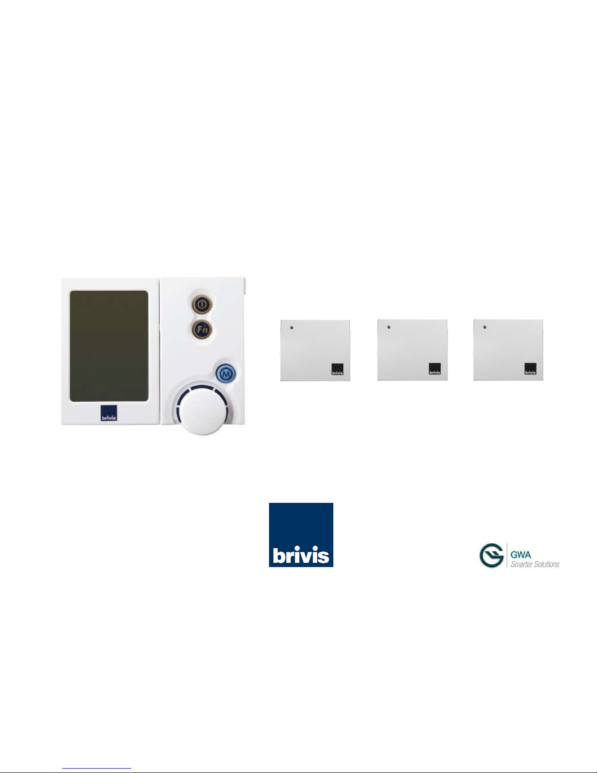
Brivis ZonePlus
Installer’s Manual
PLEASE READ THESE INSTRUCTIONS CAREFULLY BEFORE INSTALLING THIS PRODUCT
Page 2
i
Brivis ZonePlus 4-Zone Control Kit
Scope
This manual is intended to be used as a guide to the design,
installation and commissioning of Brivis ZonePlus, a Zoning Control
System for Brivis Ducted Heating and Cooling equipment. For the
installation of Brivis Heating and Integrated Cooling products
please refer to the equipment Installer Manuals. This manual is
based on Australian Standards - for all other applications, please refer to
relevant local codes and regulations.
Any deviations from these instructions may, at the discretion of Brivis,
void the warranty. As a result, the customer and/or installer may be
charged a fee for non-product warranty related call outs. Also, note
that failure to comply with these instructions may preclude Brivis from
being able to service the product.
Terminology:
Shall: Indicates a mandatory requirement of this manual.
Should: Indicates a recommended requirement of this manual.
Disclaimer
IMPORTANT NOTICE: This document is a guide only. Laws, regulations and industry
standards can vary between States and Territories. Accordingly, this guide must be read in
conjunction with, and subject to, all laws, regulations and industry standards applicable in the
State or Territory in which the products are installed. You must ensure that the installation of
the products will comply with those laws, regulations and standards, and that the
products recommended to customers are fit for the purpose for which they are intended.
Specifications subject to change without notice.
© Brivis Climate Systems Pty Ltd 2013
Table 1: Contents of ZonePlus Kit - Brivis Part No. B061006
Brivis Part No. Description Qty
B022890 NC-6 Networker 1
B024891
NT-1 Remote Temperature
Sensor
3
B061016 ZonePlus Installer’s Manual 1
B061017 ZonePlus Owner’s Manual 1
Optional Brivis Accessories (not supplied)
B024892 N-PM1 Power Module
B023178 516 Zone Module
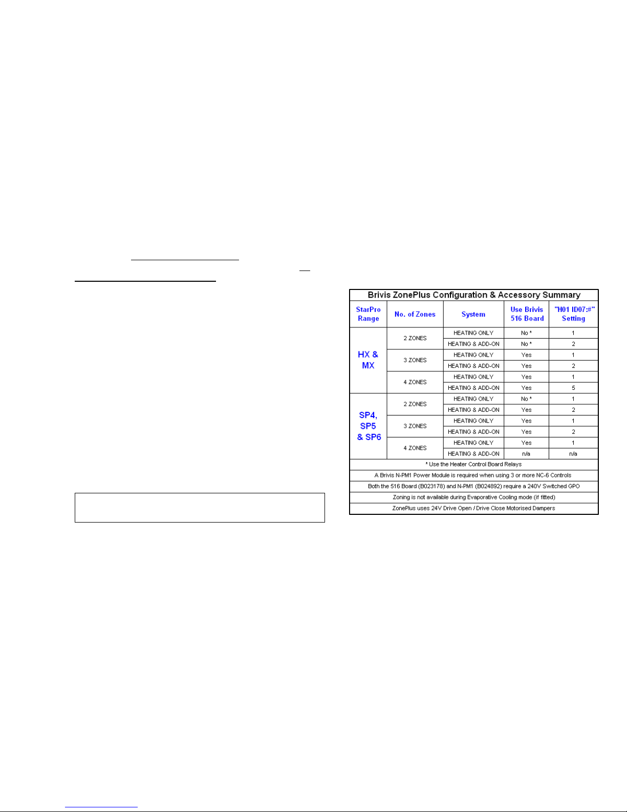
Refer to Table 2 (p.6) – System Configuration &
Accessory Summary for more information
Inspect the product to ensure it matches your order. In the
event of damage or incorrect delivery, notify supplier
immediately. Brivis accepts no responsibility for
installation of damaged or incorrect product.
Please read these installation instructions before
undertaking the installation process.
Note:
Zone Dampers are not supplied.
Page 3

ii
Table of Contents
SCOPE...................................................................................... i
APPLICATION............................................................................. 4
1.0 INTRODUCTION................................................................. 4
2.0 ZONE CONTROL SYSTEM ................................................ 4
3.0 DESIGNING THE COMFORT SYSTEM ............................. 5
4.0 GENERAL INSTALLATION CONSIDERATIONS ................ 6
5.0 INSTALLATION................................................................... 7
5.1 Locating Sensors ................................................................ 7
5.2 NC-6 and NT-1 Interconnecting Wiring ............................... 7
5.3 NC-6 Controller Installation................................................. 7
5.4 NT-1 Remote Temperature Sensor Installation................... 8
5.5 Brivis 516 Zone Module Installation .................................... 9
5.6 Brivis N-PM1 Power Module Installation ............................. 9
5.7 Heater Thermistor Installation ............................................. 10
5.8 Brivis Evaporative Cooling .................................................. 10
5.9 Zone Dampers .................................................................... 10
6.0 CONFIGURATION AND PARAMETER SETTINGS ............ 11
6.1 Standard ZonePlus (1x NC-6 and 3x NT-1) ........................ 11
6.1.1 Setting NT-1 Sensor Identification ................................... 12
6.2 ZonePlus with Multiple NC-6 and NT-1 Sensors................. 12
6.2.2 ZonePlus with all NC-6 Controllers .................................. 13
6.3 Installer Parameters............................................................ 14
6.4 Setting NC-6 Master Controller Parameters ....................14
6.4.1 Single or Multi Temperature Set Point .......................... 14
6.4.2 Common Zone.............................................................. 15
6.4.3 Refrigerated Cooling Constant Zone ............................ 15
6.4.4 Zone Configuration.......................................................15
6.4.5 Airflow Setting and Balancing ....................................... 16
6.4.6 Fan Scaling - HEATING ...............................................17
6.4.7 Fan Scaling - Refrigerated COOLING .......................... 17
6.5 Quick Start Guide ............................................................ 18
7.0 SYSTEM HAND OVER ...................................................18
7.1 SETTING THE TIME & DAY............................................18
7.2 System Operation............................................................ 19
7.3 Product and Warranty Registration .................................19
7.4 Service Notification Message .......................................... 19
7.5 ZonePlus Commissioning Information .............................19
8.0 TROUBLE SHOOTING GUIDE........................................ 19
9.0 APPENDIX ......................................................................21
Table 8: – Master Controller Parameters ............................... 22
Table 8: – Master Controller Parameters Cont’d .................... 23
Table 9: – Home Owner System Information.......................... 24
Sample System Configuration Diagrams................................ 25
Table 10: Sample Circuit Diagrams Reference ...................... 25
Page 4

1
Definitions
Zone
One room or a group of rooms, normally selected on the basis of usage
or that have similar heating or cooling needs.
Controlled Zone
A zone that is separately controlled by its own zone sensor and zone
damper. There are as many zone sensors in the home comfort system
as there are Controlled Zones.
Common Zone
A zone that is not separately controlled by its own sensor and zone
damper. It operates whenever heating or air conditioning is on.
Constant Zone
A predetermined zone, typically the largest and containing the return air,
is designated the Constant Zone and functions as a Common Zone
only during refrigerated cooling mode to ensure the minimum cooling
airflow requirements are met. The system minimum cooling airflow is
designated as 75% of the maximum system cooling airflow setting.
Multi Temperature Set Point (MTSP) ZonePlus System
The zone temperature set point can be set independently across all
Networkers and/or Temperature Sensors.
Single Temperature Set Point (STSP) ZonePlus System
The zone temperature set point is the same across all Networkers and/or
Temperature Sensors.
Fan Scaling
Brivis ZonePlus allows the system fan speed for each zone to
be individually set. HEATING and COOLING fan speeds can
both be set in the range of 1 – 16 (Min – Max).
Brivis NC-6 Networker Controller
Primary user interface with LCD display. Where multiple NC-6s are
installed, the “Master” Networker Controller can be identified by the
word “Clock” displayed adjacent to Key “5” when system is OFF. The
Master has default sensor identification “n01”.
Brivis NT-1 Remote Temperature Sensor
Zone temperature sensor with LED that blinks during communication
with Master NC-6. Default NT-1 sensor identification is “n02”.
Additional NC-6 Networkers can be used in place of up to 3x NT-1
sensors.
Sensor
Both the NC-6 and NT-1 function as zone (room) temperature sensors
– in this context, the word “sensor” in this manual can apply to both.
Adaptive Zoning (non-ZonePlus Control System)
One Brivis Networker Controller with zones, the ON and OFF times of
which are controlled by the Networker.
The minimum and maximum HEATING fan speeds are set during
commissioning and this range is divided into equal segments depending
upon the number of zones. Only maximum REFRIGERATED
COOLING fan speed can be set and is fixed during operation.
Adaptive Zoning is not covered in this manual. Please refer to the
Brivis StarPro Heater Installer Manual for more information.
Page 5
2
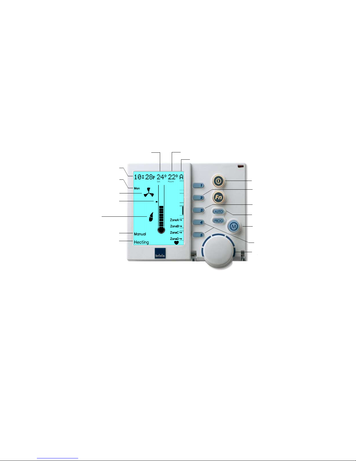
Diagram 1a. NC-6 Networker – Key Functions
* Active
with MTSP systems only
** Active with STSP systems only
Mode
(Heating / Cooling)
Advance Period
Auto Program
or Manual
On / Off
Zone Key*
Mode
Selected
Zone Selected*
Set Temperature Room (zone) Temperature
Rotary Dial
Set Temp
Marker
Fan
Symbol
Day
Auto Program
or Manual
Digital
Clock
Zone Keys**
Flame
Symbol
Page 6
3
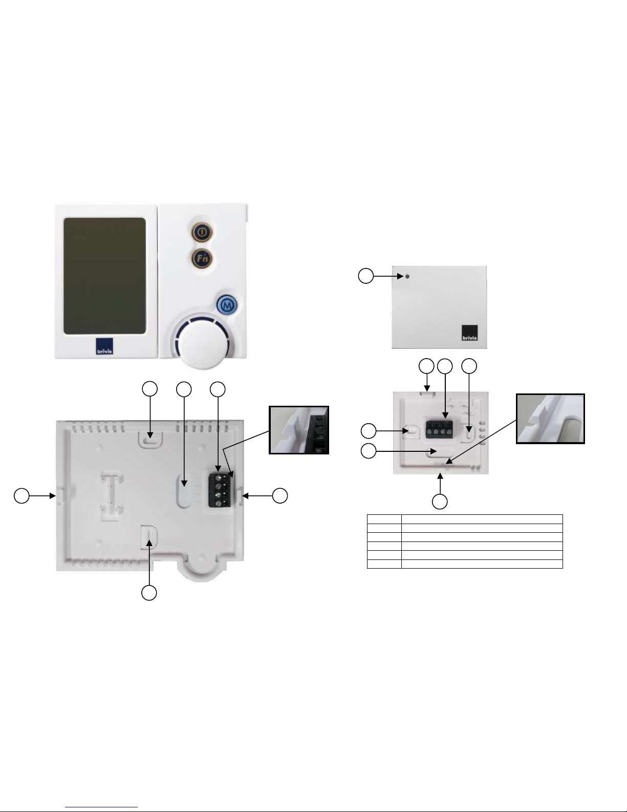
Diagram 1b. NC-6 and NT-1 – Physical Characteristics
Item Description
1
Slot for wall mounting screw
2
Front face retaining clip
3
Slot for 2-wire bus cable
4
2-wire bus terminal block (TW1 & TW2)
5
NT-1 Sensor LED
5
1
1
2 2
3
4
1
1
2
2
3
4
Page 7
4
Application
ZonePlus may be used on the following Brivis Ducted
Systems:
• Brivis StarPro Ducted Gas Heaters produced after 20 May 2013
(serial number greater than 995000)
• Brivis Dual Comfort Systems (Brivis StarPro Heaters and ICE
Refrigerated Cooling)
• Brivis StarPro Ducted Gas Heaters and Brivis Evaporative Cooling
• Zoning is not available during Evaporative Cooling mode
• The NC-6 Master Controller, or any other ZonePlus NC-6,
where fitted, will operate a Brivis Evaporative cooler with all
normal features and functionality
1.0 INTRODUCTION
Brivis ZonePlus brings the possibility of total comfort control to occupants
by providing the precise amount of heating or cooling into each space, or
zone, within a home.
A zoning system is a heating and/or cooling control system that
maintains each zone at a predetermined temperature set point.
ZonePlus can control up to four independent zones.
Brivis ZonePlus design objectives are to:
• direct conditioned air based on the individual needs of each zone
• keep the sound produced by the system low enough that occupants
do not find it objectionable
• seamlessly interface with and protect the Brivis heating and cooling
climate system
• maintain the minimum airflow necessary to keep the heating and
cooling equipment running efficiently
2.0 ZONE CONTROL SYSTEM
It’s important to keep in mind what a zoned system can and cannot do.
A zone control system is only part of a complete heating and cooling
system. A properly selected heating and/or cooling system has a
defined heating and cooling capacity, so it is important to specify the
system’s capabilities. In particular, how many zones can be operated
individually or simultaneously in both heating or cooling modes at specific
design conditions.
When designing a zoned home comfort system, there are two
primary considerations, dependent on the needs and
requirements of the home owners.
1. system designed primarily for energy savings – used
primarily to shut off unoccupied zones
2. system designed primarily for comfort – used primarily to
control temperatures in diverse zones
Both applications can be either Multi Temperature Set Point or
Single Temperature Set Point.
Note:
ZonePlus systems should only be installed by
authorised Brivis Dealers who have successfully completed
the Brivis ZonePlus Training Module.
Note:
All system configuration and parameter settings shall be
recorded in the Appendix (Table 7 & Table 8) of this manual
and retained by home owner for future reference.
Page 8

5
• Multi-Temperature Set Point systems can have up to four
controlled zones where each zone has independent
temperature set points. We do not recommend the use of a
Common Zone in these applications
• Single Temperature Set Point systems can have up to four
controlled zones where each zone has the same
temperature
set point. An optional Common Zone is recommended for this
type of application
A zoning system reduces the effective size of the air
distribution system as dampers open and close to meet the
needs of the zones. The aim is to ensure that the distribution
system does not become so small that the reduction in airflow
causes one or more of the following problems:
• excessive air, noise or drafts
• the equipment shuts down because predetermined limits are
exceeded
• the life of the equipment is reduced through stress-related excess
temperatures or cycling
3.0 DESIGNING THE COMFORT SYSTEM
Objective: to maintain a minimum airflow through the system when only
one zone requires conditioning, yet still provide sufficient airflow when all
design zones require conditioning, for both heating and cooling modes.
Multi Temperature Set Point - Design Framework:
• Each zone has independent temperature set points
• In Heating mode there is no requirement for a Constant Zone
• In Refrigerated Cooling mode we recommend you nominate your
largest zone as the Constant Zone (typically default value Zone A “ID93:1”) to satisfy the system’s minimum air quantity requirement.
Usually this is the zone which incorporates the return air grille
• A Common Zone is not recommended as MTSP ZonePlus offers
optimum independent zone temperature control
Single Temperature Set Point - Design Framework:
• Each zone has the same temperature set point
• The design guidelines allow for the inclusion of a Common Zone
Step by step tasks:
1. Assign Zones
a. Determine, in consultation with the homeowner, whether the system
is to be designed primarily for comfort or energy savings
b. Assign the zones and determine how many zones are to operate
simultaneously, for both heating and cooling modes
c. Determine whether the system is to be Single Temperature Set Point
or Multi Temperature Set point
d. Complete the Home Owner Comfort Schedule (in the ZonePlus
Owner’s Manual) to ensure that the installed system will meet the
home owner requirements
2. Size the equipment
a. Determine Design Conditions; i.e. Indoor Control Temperatures at
Ambient Design Temperatures
b. Calculate peak heating and cooling load estimates for each zone (e.g.
Brivis SuperSizeGuide)
c. Calculate cooling BLOCK LOAD (maximum simultaneous load)
d. Satisfy both kW and AIRFLOW capacity requirements for both
heating and cooling modes
Page 9
6
3. Ductwork & Fittings
Size ductwork and fittings in accordance with good industry
practice; e.g. Australian Standard HB276 which prescribes
ductwork and diffusion equipment selection parameters. Do
not undersize ductwork and fittings. Ensure recommended
system minimum airflow requirements are met for both heating
and cooling modes.
4.0 GENERAL INSTALLATION
CONSIDERATIONS
• The system design requirements would have been determined in
consultation with the home owner to correctly specify the
configuration and capabilities of the ZonePlus comfort control system
• Ensure all power to all equipment and controls are off prior to
connecting
• Ensure that all electrical connections are tight and secure. Install in
accordance with these instructions and your local laws, regulations
and standards
• Use only twin-core, ‘figure 8’ – 0.75mm² cable for 2-wire bus
communications with less than 100m in total length
• Ensure that the 2-wire bus cable is routed in a protected and safe
manner, away from mains power cabling
• For additional product information refer to the Brivis product’s specific
Installer Manual
Varying Brivis StarPro heaters have different on-board
capabilities. See Table 2 for details of zone combinations
and accessory requirements.
Table 2: System Configuration & Accessory Summary
Note: Unless otherwise specified, all instructions regarding ‘cooling’
relate to Brivs ICE Refrigerated Add-On Systems.
Page 10
7
5.0 INSTALLATION
5.1 Locating Sensors
For proper operation, each sensor must accurately monitor the
temperature within its zone.
Guidelines:
Sensor should be mounted:
• Approximately 1.5m above floor level (ensure hole into wall cavity is
properly sealed)
• Close to the centre of the zone on an internal wall
• On a section of wall that does not contain pipes, electrical wires,
antenna cables or ductwork
Sensor should NOT be mounted:
• Where it is exposed to direct sunlight or other heat sources which
may cause a false reading
• Near or in the path of supply air outlets or return air grilles
• On outside walls, near windows or doors leading to outside
• In areas with poor air circulation such as recesses or behind doors
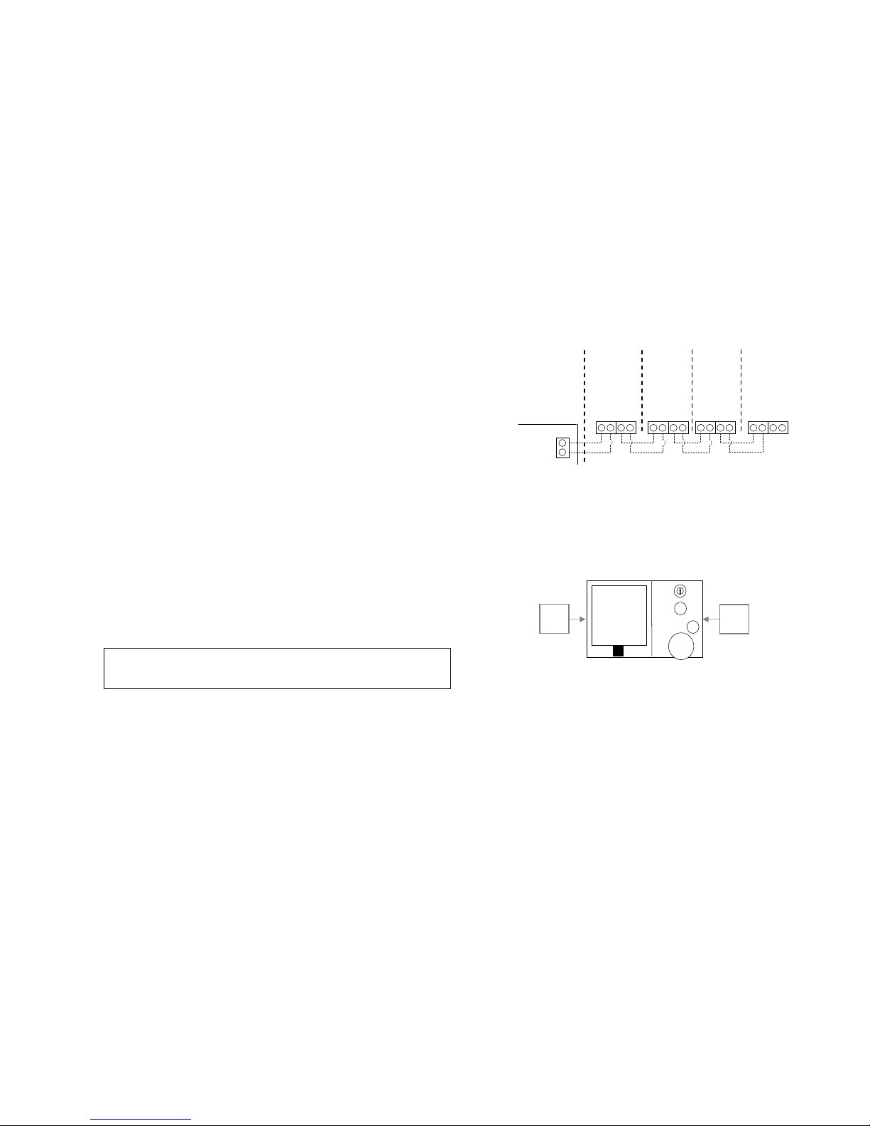
5.2 NC-6 and NT-1 Interconnecting Wiring
Below is the recommended method of parallel inter-connection.
It is possible to interconnect via this method in any
configuration, i.e. Zone A D, Zone D B and Zone B C.
5.3 NC-6 Controller Installation
The NC-6 Master Controller contains the primary user interface
and should be located in a position that enables convenient
user access, typically in Zone A.
1. Backing Plate Removal
• Unclip the backing plate from the user interface by
disengaging the right and left clip. Separate once this is
achieved
NC-6, Brivis Part No: B022890
Right
Clip
Left
Clip
M
Fn
Diagram 2.
Note: Do not install the wiring with the power turned on, as this may
cause the fuse to blow on the Heater Control Board.
Diagram 2. Standard 4-Zone System Sensor Wiring
NC-6
MASTER
ZONE A
TW1
TW2
TW1
TW2
TW1 TW2
NT-1
SENSOR
ZONE D
TW1 TW2
NT-1
SENSOR
ZONE C
TW1 TW2
TW1 TW2
NT-1
SENSOR
ZONE B
TW1 TW2 TW1 TW2
HEATER
CONTROL
BOARD
TW1
TW2
Page 11
8
• Connecting 2-wire bus cables
• Run a twin wire cable from the heater to the Master
Controller location
• Run an additional twin wire from the Master Controller to
the location of the first NT-1
2. Connection of bus cables to NC-6 backing plate
• There are two terminal blocks and both are marked TW1
TW2. One 2-wire bus cable must be dedicated to one of
the two terminal blocks and not shared across the two
blocks
• Draw both wires (2x ‘figure 8’ cable) from the wall cavity
and feed them through the large slot in the backing plate
• Connect the 2-wire bus cable from the heater to the NC-6
TW1 and TW2 terminals in the same block
• Repeat the above for the second 2-wire bus cable for first
NT-1 and insert into the second terminal block
3. Mounting the backing plate
• Position the backing plate on the wall and mark the two
mounting positions on the wall
• Insert wall plugs (field supplied) in the marked positions to
suit the Ø3.5mm (6 gauge) screws supplied with the NC-6
• Secure backing plate to the wall, push back excess 2-wire
bus cable into the wall cavity and seal the hole to prevent
drafts
• If there are more than two (2) NC-6 Controllers in the
system, DO NOT re-assemble at this stage
4. Heater Connection
• Connect the 2-wire bus cable from the NC-6 to the
terminals marked TW1 and TW2 on the heater’s electronic
control board
5.4 NT-1 Remote Temperature Sensor
Installation
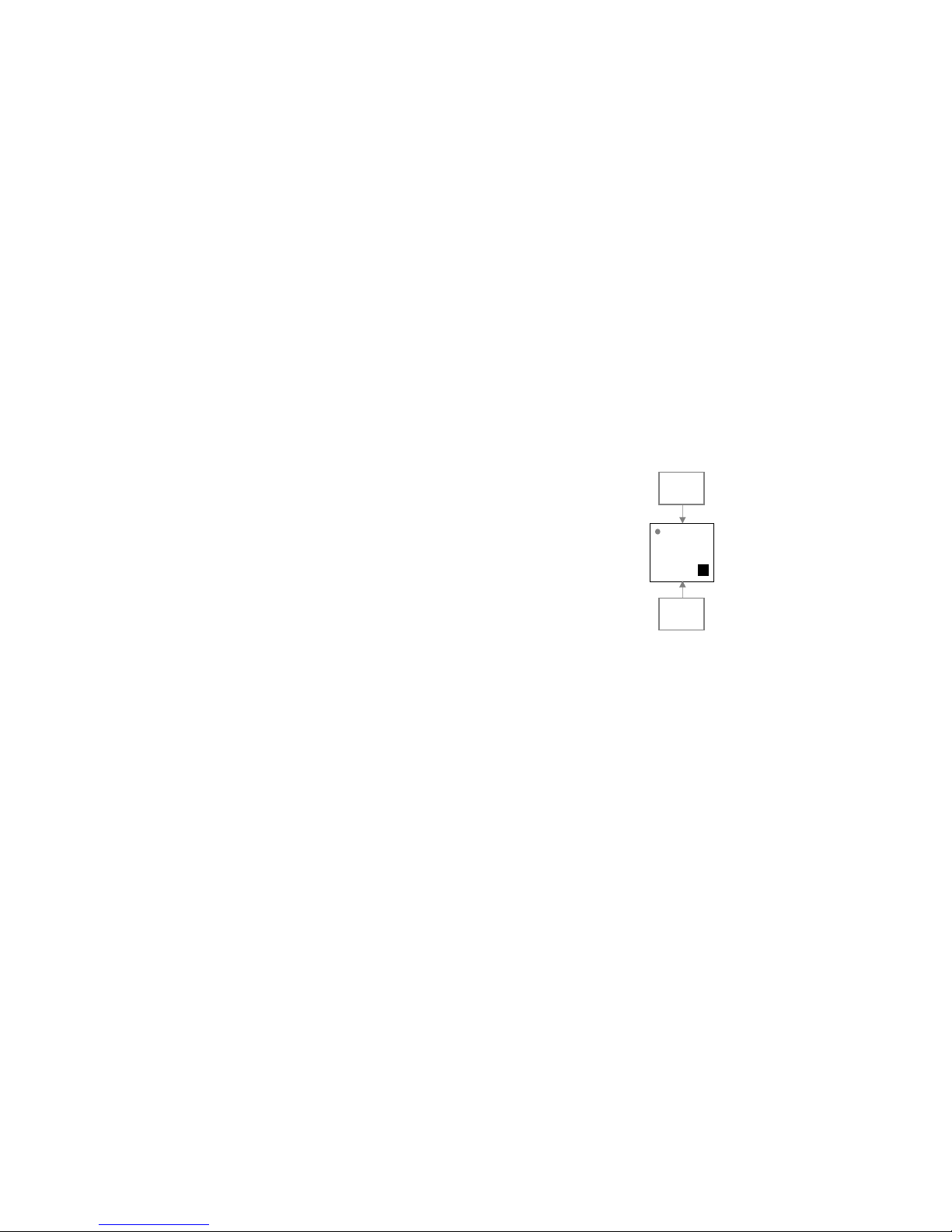
1. Backing Plate Removal
• Unclip the backing plate from the user interface by
disengaging the top and bottom clip. Separate once this is
achieved
2. Connecting 2-wire bus cable
• Run cable to the position of all temperature sensors as
shown in Diagram 2, p.7
• There should be enough 2-wire bus cable at each NT-1,
excluding the last, to enable daisy chain connection
3. Connection of bus cables to NT-1 backing plate
• There are two terminal blocks on the backing plate of the
NT-1. One 2-wire bus cable must be dedicated to one of
brivis
Bottom
Clip
Top
Clip
Diagram 3.
NT-1, Brivis Part No: B024891
Page 12
9
the two terminal blocks and not shared across the two
blocks
• Draw both wires from the wall cavity and feed them through
the large slot in the backing plate
• Connect one of the 2-wire bus cables to the first terminal
block and the other 2-wire bus cable to the second terminal
block
4. Jumper Change for Unit Identification
• All NT-1 sensors are factory pre-set with unit identification
number “n02”. For multi-sensor systems additional NT-1
sensors must be assigned a unique unit identification
number. This is done by changing the jumper location from
“I/E” to: Refer to section 6.1.1 p.12
5. Mounting the backing plate
• Position the backing plate on the wall and mark the two
mounting positions on the wall
• Insert wall plugs (field supplied) in the marked positions to
suit the Ø3.5mm (6 gauge) screws supplied with the NT-1
• Secure backing plate to the wall, push back excess 2-wire
bus cable into the wall cavity and seal the hole to prevent
drafts
• Re-assemble the NT-1 - take care not to bend the
connector pins when re-assembling
5.5 Brivis 516 Zone Module Installation
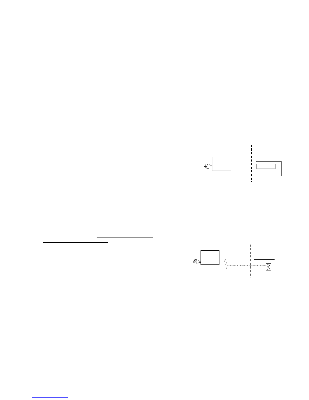
If a Brivis 516 low voltage Zone Module is required (see Table
2, p.6), install a 240VAC fixed switched GPO, installed
adjacent to the switched GPO for the heater.
Connect the 6 pin plug (loom) from the Zone Module to the
terminal marked "Ext Zone Module" on the heater control
board (see Diagram 4).
For detailed instructions please refer to the Brivis 516 Module
Installer’s Manual.
5.6 Brivis N-PM1 Power Module Installation
A Power Module is required when three or more NC-6
Networkers are part of the system (see Table 2, p.6).
The N-PM1 Power Module requires a 240VAC fixed switched
GPO, installed adjacent to the switched GPO for the heater.
Connect the 2-wire bus exiting the Power Module to the TW1
and TW2 terminals on the heater control board.
Diagram 5.
Diagram 4.
516 Module, Brivis Part No: B023178
240V,
50Hz
Plug
Loom
516
Module
HEATER
CONTROL
BOARD
Ext Zone Module
2-Wire Bus
N-PM1, Brivis Part No: B024892
240V,
50Hz
Plug
N-PM1
HEATER
CONTROL
BOARD
TW2
TW1
Page 13
10
5.7 Heater Thermistor Installation
• For Brivis StarPro Heating only applications the heater
thermistor must be installed in accordance with the
instructions for the heater
• For Dual Comfort systems (Brivis StarPro Heating and
Brivis ICE Add-On applications), the heater thermistor must
be installed in the discharge pop (outlet) of the cooling
coil. Refer to the associated Brivis ICE Installer Manual for
details
• Amongst other primary functions, this thermistor also
provides Low Temperature Limit protection. If the cooling
coil temperature remains at or below 7
o
C for 3 minutes, the
compressor will cycle off for a minimum of 5 minutes, and
until the cooling coil temperature reaches 10oC
• During this off cycle time the indoor fan will continue to run
• If this condition persists, confirm the system design and/or
operation is able to maintain the minimum recommended
cooling airflow requirements
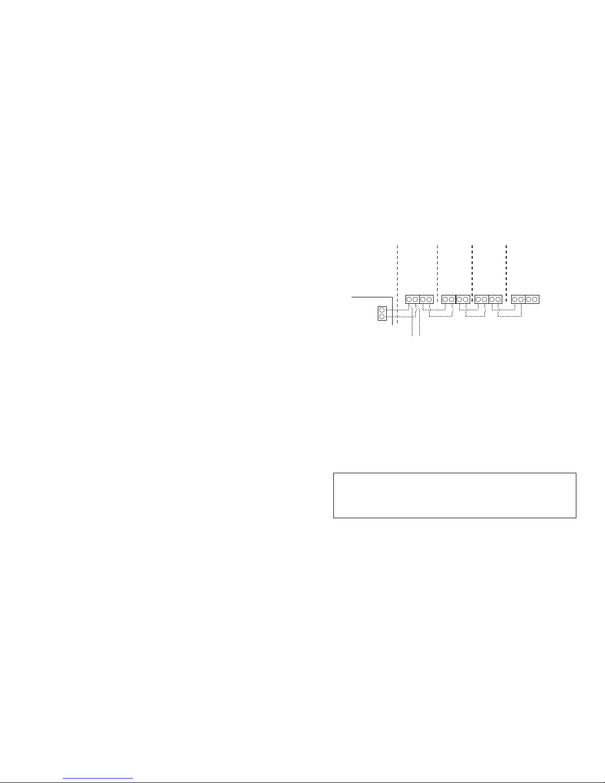
5.8 Brivis Evaporative Cooling
Operating a Brivis evaporative cooler and a Brivis heater
requires the two left terminals (TW1 & TW2) connected to the
heater and the two right terminals connected to the cooler.
• Zoning is not available during Evaporative Cooling mode
• The Master Controller, or any other ZonePlus NC-6, where
fitted, will operate a Brivis Evaporative cooler with all normal
features and functionality
5.9 Zone Dampers
24 Volt Drive Open / Drive Closed zone dampers are to be
field supplied by installer.
Note:
Zone dampers must be insulated in accordance with
local codes, particularly in cooling systems to prevent
condensation and resulting potential component or property
damage.
TW1
TW2
TW2
Diagram 6. Wiring in the Evaporative Cooler
HEATER
CONTROL
BOARD
TO
EVAPORATIVE
COOLER
NC-6
MASTER
ZONE A
TW1
TW2
TW1
TW2
TW1
NT-1
SENSOR
ZONE D
TW1 TW2
NT-1
SENSOR
ZONE C
TW1 TW2
TW1 TW2
NT-1
SENSOR
ZONE B
TW1 TW2 TW1 TW2
Page 14

11
6.0 CONFIGURATION AND PARAMETER
SETTINGS
To configure the system and set parameters follow these
steps:
1. Set NT-1 Sensor IDs
2. Set NC-6 Sensor IDs
3. Installer Parameters
4. Set Networker Parameters
6.1 Standard ZonePlus (1x NC-6 and 3x NT-1)
Important Notes:
• All NC-6 Networker Controllers come configured as ‘Master’
devices by default, with the sensor identification pre-set to
“n01”
• There can be only one Master Controller set to “n01” in a
ZonePlus system
• All NT-1 Remote Temperature Sensors come configured as
‘Slave’ devices by default, with sensor identification pre-set
to “n02 ID00:2”
• Zones sensors must be assigned to dampers; see 6.4.4,
p.15
Table 3: Standard 4-Zone System Configuration
Zone ID
Sensor
Type
Sensor
ID
Factory
Setting
Sensor
ID
System
Setting
To modify
Sensor ID
System
Setting
Zone A NC-6 “n01” “n01” n/a
Zone B NT-1 “n02” “n02” n/a
Zone C NT-1 “n02” “n03” Jumper “S3”
Zone D NT-1 “n02” “n04” Jumper “S4”
Always set and record all parameters in the Appendix.
Page 15
12
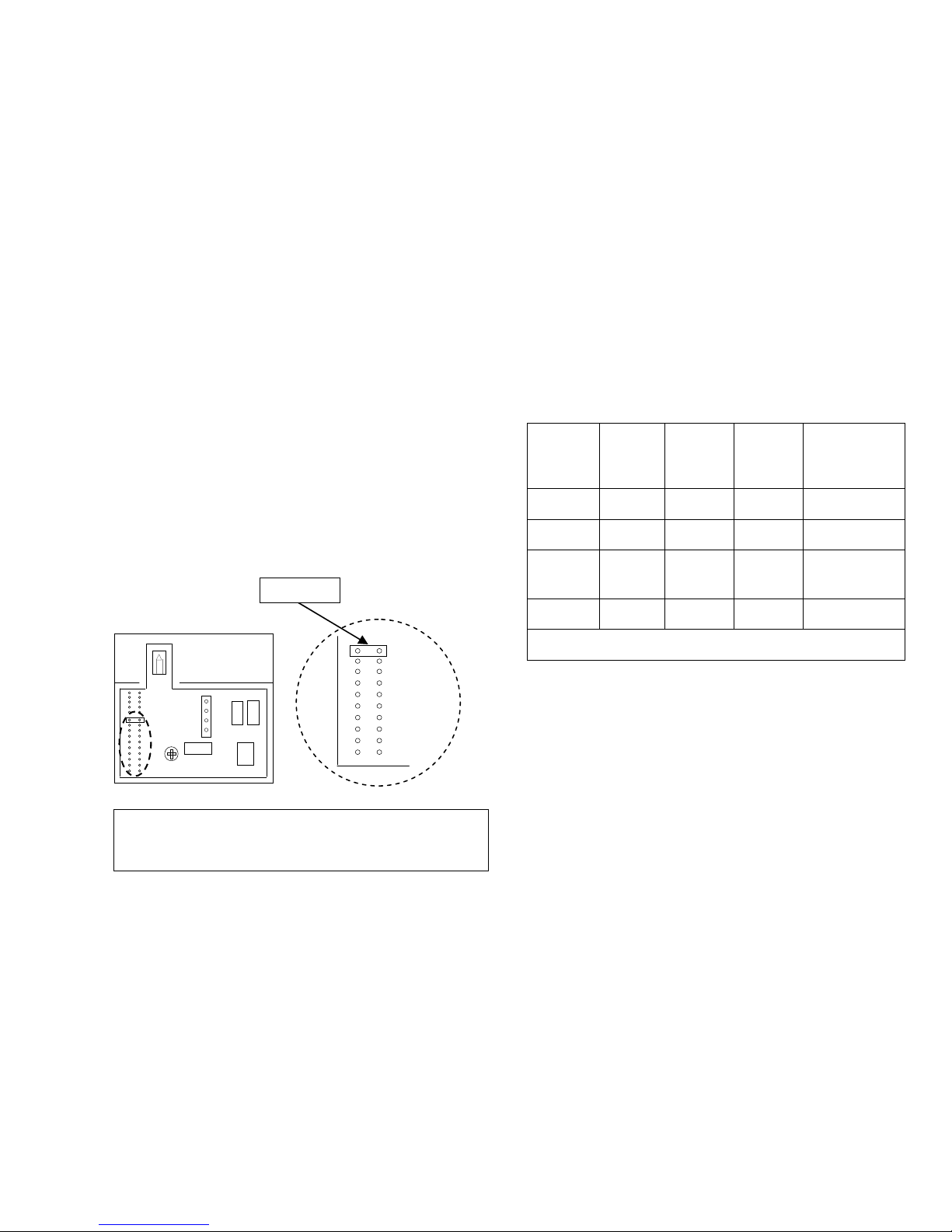
6.1.1 Setting NT-1 Sensor Identification
When the system contains more than one NT-1 device the
sensor identification parameter setting for additional sensors
must be changed using the Jumper inside the NT-1.
JUMPER
For NT-1 sensors other than the NT-1 for Zone B, change the
default position of the Jumper pin from position “I/E” to
position:
“S3” for Zone C
“S4” for Zone D
Jumper pin positions “S5” to “S9” are reserved for future
development.
6.2 ZonePlus with Multiple NC-6 and NT-1
Sensors
Table 4: 4-Zone System Configuration with 2xNC-6 and 2x
NT-1 (example)
Zone ID
Sensor
Type
Sensor
ID
Factory
Setting
Sensor
ID
System
Setting
To modify
Sensor ID
System
Setting
Zone A NC-6 “n01” “n01” n/a
Zone B NT-1 “n02” “n02” n/a
Zone C NC-6 “n01” “n03”
Installer
Parameter
“ID00:3”
Zone D NT-1 “n02” “n04” Jumper “S4”
Always set and record all parameters in the Appendix.
Important Notes:
• NT-1 Sensors should be wired, configured and fully
installed
• Only the NC-6 Controller backing plates should be wired
and installed
Power up the system in the following sequence:
• 516 Network Module (if applicable)
• N-PM1 Power Module (if applicable)
• Heater
• Cooling System (if applicable)
I/E
S2
S3
S4
S5
S6
S7
S8
S9
AMBIENT
Jumper Pin
I/E
S2
S3
S4
S5
S6
S7
S8
S9
AMBIENT
Diagram 7.
Note: NT-1 Temperature Sensors contain a green LED in the
top left hand corner. Whenever the NT-1 is being access by
an NC-6, the LED flashes once every second.
Page 16
13
Setting Sensor Identification on an NC-6 when
used as a Slave (refer Table 4. example)
• Determine which NC-6 Controller will be the Master and
which one will be the Slave
• Mount the proposed NC-6 Slave onto the backing plate of
the NC-6 that has power supplied directly from the heater
control board
• Change the NC-6 Slave identification number to “3” by
accessing Installer Parameters (see 6.3, p.14)
• Fit the NC-6 Slave to its designated zone backing plate only
after the unit ID has been changed
• Mount the Master Controller onto its backing plate – this will
not require a unit ID change
• Once an NC-6 has been designated a ‘Slave’, Installer
Parameters will no longer be accessible from this NC-6.
The Master Controller must then be used to access the
installer parameters
6.2.2 ZonePlus with all NC-6 Controllers
All NC-6 controllers that are used in place of NT-1 sensors
must have their sensor ID altered so that it operates as a slave.
Important Notes:
• Only the NC-6 Controller backing plates should be wired
and installed
Power up the system in the following sequence:
• 516 Network Module (if applicable)
• N-PM1 Power Module (if applicable)
• Heater
• Cooling System (if applicable)
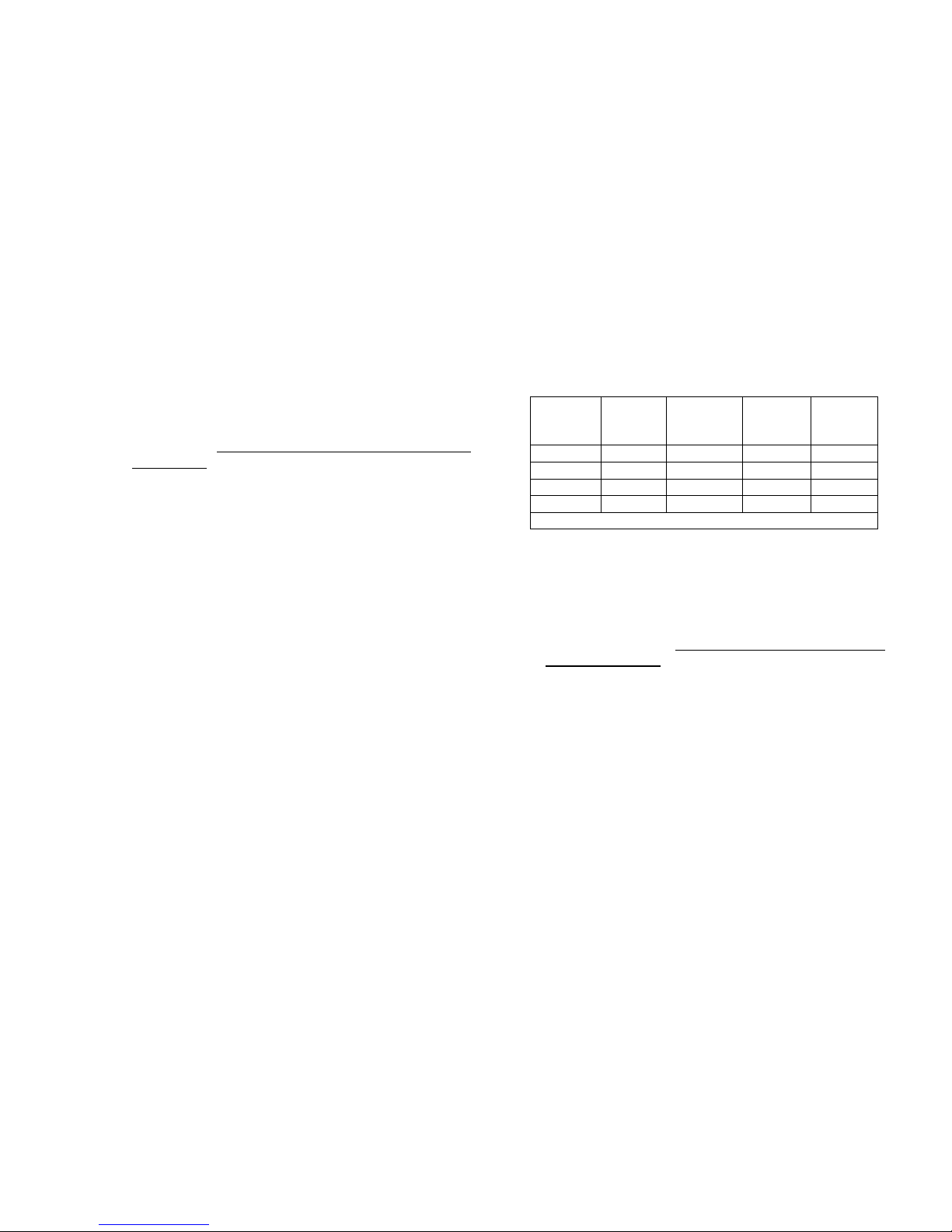
Table 5: 4-Zone System Using All NC-6 Controllers
(example)
Zone ID
Sensor
Type
Function
Unit ID
Factory
Setting
Unit ID
System
Setting
Zone A NC-6 Master “n01” “n01”
Zone B NC-6 Slave “n01” “n02”
Zone C NC-6 Slave “n01” “n03”
Zone D NC-6 Slave “n01” “n04”
Always set and record all parameters in the Appendix.
Setting Sensor Identification on an NC-6 when
all are used as Slaves (refer Table 5. example)
• Determine which NC-6 Controller will be the Master and
which ones will be Slaves
• Mount one of the proposed NC-6 Slaves onto the backing
plate of the NC-6 that has power supplied directly from the
heater control board
• Change the NC-6 ID number to “2” by accessing Installer
Parameters (see 6.3, p.14)
• Repeat for the remaining two Slaves and set unit ID to “3”
and “4” respectively
• Fit the NC-6 Slaves to their designated zone backing plates
only after all unit ID have been changed
• Mount the Master Controller onto its backing plate – this will
not require a unit ID change
• Once an NC-6 has been designated a ‘Slave’, Installer
Parameters will no longer be accessible from this NC-6.
The Master Controller must then be used to access the
installer parameters
Page 17

14
6.3 Installer Parameters
Accessing
• Press Key “5” on the proposed Slave NC-6 and the screen
will display the message "Clock setting mode". Ensure that
the word “Clock” is flashing on the display before
proceeding
• Press and hold Keys “2” & “4” simultaneously, until the
screen displays the message "Installer parameter
access"
• All setup parameters, once entered, are automatically
saved
Heater Installer Parameters
• Set and record heater installer parameters (“H01 ID01” –
“H01 ID08”) as per Table 7 in the Appendix.
• Press “M” (Mode) to access Master Controller Parameters
(Table 8, p.22)
• Press On/Off to exit
6.4 Setting NC-6 Master Controller Parameters
Important Note:
The Installer Parameter value (“H01 ID07 :#”) must be set in 6.3
(p. 14) to enable specific zoning options before proceeding.
Table 8 (p.22) details all Installer Parameters that may be
made available for setting up the ZonePlus system.
All other parameter values must be set in ascending
sequential order, with the exception of parameter “n01
ID92” (for Multi Temperature Set Point Systems, which
MUST BE SET PRIOR
to setting all other NC-6 parameters).
Set and record all Master Controller Parameters in Table 8
in the Appendix.
6.4.1 Single or Multi Temperature Set Point
The default ZonePlus configuration setting is Single
Temperature Set Point. To activate Multi Temperature Set
Point, parameter “n01 ID92” must be changed from the factory
default setting of “0” to “1”.
Note:
When Refrigerated Cooling is installed, the zone
sensor IDs are forced to match those used for Heating. For
example if Heating Zone B sensor ID was set to “n02”, then
Refrigerated Cooling Zone B sensor ID would also be set to
“n02”.
Page 18

15
6.4.2 Common Zone
The default ZonePlus setting of Single Temperature Set
Point also includes an enabled Common Zone for both
Heating and Cooling. The Common Zone and one other zone
must share a common temperature sensor. The default is set
to Zone A (Master Control - sensor ID “n01”).
The Common Zone parameter settings are:
Heating: “n01 ID15:1” and “n01 ID16:1”
Cooling: “n01 ID01:1” and “n01 ID02:1” (if cooling is fitted)
These do not need to be adjusted.
When Multi Temperature Set Point is enabled (“n01 ID92 :“1”)
these Common Zone parameters are disabled.
6.4.3 Refrigerated Cooling Constant Zone
A Constant Zone is required to maintain minimum refrigerated
cooling airflow in MTSP systems. The parameter “n01 ID93:1”
assigns Zone A by default.
To alter the nominated Constant Zone from the default, set “2”
for Zone B, “3” for Zone C, or “4” for Zone D.
Assigning “0” will disable the Constant Zone. This should be
done when the system operates only in circumstances where
the minimum cooling airflow requirements are met in all
possible zoning configurations.
The Constant Zone is not active during Heating mode.
6.4.4 Zone Configuration
To enable zoning, Heating Installer Parameter “H01 ID07:0”
must change to either “1”, “2”, or “5”.
Set “H01 ID07:x” where x = the Parameter Value for your
system from Table 2, p.6.
All zone parameters must be entered into the Master Controller
in a sequential order; i.e. the parameters for Zone B cannot be
accessed until Zone A parameters have been set.
Deleting zone parameters must be conducted in the reverse
order to entering; i.e. Zone D and its zone relay must be
deleted before Zone C can be deleted.
The zoning Installer Parameters to consider can be accessed
via the Master Controller, under unit “ID n01”.
These include:
For Refrigerated Cooling (if applicable)
The NC-6 Master Controller is preset for Common Zone
(Cooling) operation, i.e. “n01 ID01:1”
For Heating
The NC-6 Master Controller is preset for Common Zone
(Heating) operation, i.e. “n01 ID15:1
Page 19

16
Table 6: Heating & Refrigeration Zoning Parameters
Cooling
Parameter
ID
Heating
Parameter
ID
Feature
ID03 ID17 To enable Zone A
ID04 ID18 Select relay for Zone A
ID05 ID19 Select sensor No: for Zone A
ID06 ID20 To enable Zone B
ID07 ID21 Select relay for Zone B
ID08 ID22 Select sensor No: for Zone B
ID09 ID23 To enable Zone C
ID10 ID24 Select relay for Zone C
ID11 ID25 Select sensor No: for Zone C
ID12 ID26 To enable Zone D
ID13 ID27 Select relay for Zone D
ID14 ID28 Select sensor No: for Zone D
For more details please refer to Table 8:- Master Controller
Parameters in the Appendix.
Example: Setting up Zone A – Dual Comfort
1. Access the Installer Parameters (6.3, p.14)
2. Push the Mode Key until “n01” is displayed on the
Master Controller interface, top left hand corner
3. Press Key “1” and scroll to parameter “ID03”. This
parameter value allows you to enable Zone A for
Refrigerated Cooling
4. Rotate the dial and change the parameter value from “0”
to “1” to enable Zone A
5. Press Key “1”, rotate the dial and scroll to parameter
ID04. This parameter value nominates the relay that will
supply power to the zone motor
6. Rotate the dial to either relay number that is driving the
associated zone damper motor, either 1, 2, 3, or 4 for a
four zone system
7. Press Key “1” and scroll to parameter ID05. This value
allows you to select the associated zone’s sensor ID
8. Rotate the dial to select the correct sensor for the zone,
either “1”, “2”, “3”, or “4” for a four zone system
9. To setup Zone B for Refrigerated Cooling conduct the
above steps for ID06, ID07 and ID08
10. Once all zoning parameter changes are complete press
the On/Off button to save and exit
The process in the above example also applies to setting up
the zones for Heating. Please refer to the parameter numbers
in this section for Heating and Refrigerated Cooling or Table 8,
which is where all Parameter values should be recorded.
6.4.5 Airflow Setting and Balancing
Fan Scaling
Fan scaling customises the required heating or cooling airflow
for individual zones. Fan speed settings range from 1 – 16
(Min – Max) for each zone.
Airflows should be set in accordance with design conditions;
care should be taken not to cause drafts or noise concerns.
We recommend balancing dampers be fitted in the ducting
system (e.g. at supply air outlet, at the branch take-off, or via
an in-line ductwork damper) for final airflow adjustments.
Page 20

17
6.4.6 Fan Scaling - HEATING
• The procedure for either Single Temperature Set Point
(STSP) or Multi Temperature Set Point (MTSP) systems is
the same.
• Ensure all balancing dampers for all outlets are fully open
• Change “n01 ID:105” default setting from “0” to “1” to enable
Fan Scaling
• Set the fan speed (1 – 16) for each zone
• “n01 ID:106” = Common Zone (STSP systems only*)
• “n01 ID:107” = Zone A
• “n01 ID:108” = Zone B
• “n01 ID:109” = Zone C
• “n01 ID:110” = Zone D
• Once “n01 ID:xxx” appears, the fan will automatically start
• Rotate the dial on the NC-6 to set the initial desired airflow for
the zone
• To ensure that each supply outlet within the zone receives its
correct proportion of the total airflow for that zone, check each
outlet and balance accordingly – note that this may require
refinement of the initial zone fan speed setting
• Adjust the intital fan speed setting for the zone if required
• Set all remaining zone Heating fan speeds in similar fashion
• Press ON/OFF to exit
* For MTSP sytems, the Common Zone Fan Scaling set up will
not be available, see 6.4.1, p.14
Record all system configuration and parameter settings in
the Appendix.
6.4.7 Fan Scaling - Refrigerated COOLING
• The procedure for either STSP or MTSP systems is the same.
• Ensure all balancing dampers for all outlets are fully open
• Any single zone, or single zone with Common Zone must be
capable of handling at least 75% of the maximum nominal
Cooling airflow
• Change “n01 ID:111” default setting from “0” to “1” to enable
Fan Scaling
• Set the fan speed (1 – 16) for each zone
• “n01 ID:112” = Common Zone (STSP systems only*)
• “n01 ID:113” = Zone A
• “n01 ID:114” = Zone B
• “n01 ID:115” = Zone C
• “n01 ID:116” = Zone D
• Once “n01 ID:xxx” appears, the fan will automatically start
• Rotate the dial on the NC-6 to set the initial desired airflow for
the zone
• To ensure that each supply outlet within the zone receives its
correct proportion of the total airflow for that zone, check each
outlet and balance accordingly – note that this may require
refinement of the initial zone fan speed setting
• Adjust the intital fan speed setting for the zone if required
• Set all remaining zone Cooling fan speeds in similar fashion
• Press On/Off to exit
* For MTSP sytems, the Common Zone Fan Scaling set up will
not be available, see 6.4.1, p.14
Record all system configuration and parameter settings in
the Appendix.
Page 21
18
6.5 Quick Start Guide
Once all parameters have been set:
1. At the Master Controller press the “M” button until
“Heating” is displayed at the bottom of the screen
2. Press the On/Off button to call for heating
3. Increase the temperature set point to above room
temperature for Zone A only
4. Confirm Zone A is operating as intended
5. Repeat independently for the remaining zones
6. Turn on all zones to confirm system operation
7. Turn the unit off once Heating setup is confirmed
8. Press the “M” button until “Cooling” is displayed at the
bottom of the screen
9. Press the On/Off button to call for cooling
10. Decrease the temperature set point to below room
temperature for Zone A only
11. Confirm Zone A is operating as intended
12. Repeat independently for the remaining zones
13. Turn on all zones to confirm system operation
14. Turn the unit off once Cooling setup is confirmed
7.0 SYSTEM HAND OVER
1. Set the time and day
2. System operation
3. Product and warranty registration
4. Service notification
5. ZonePlus commissioning information
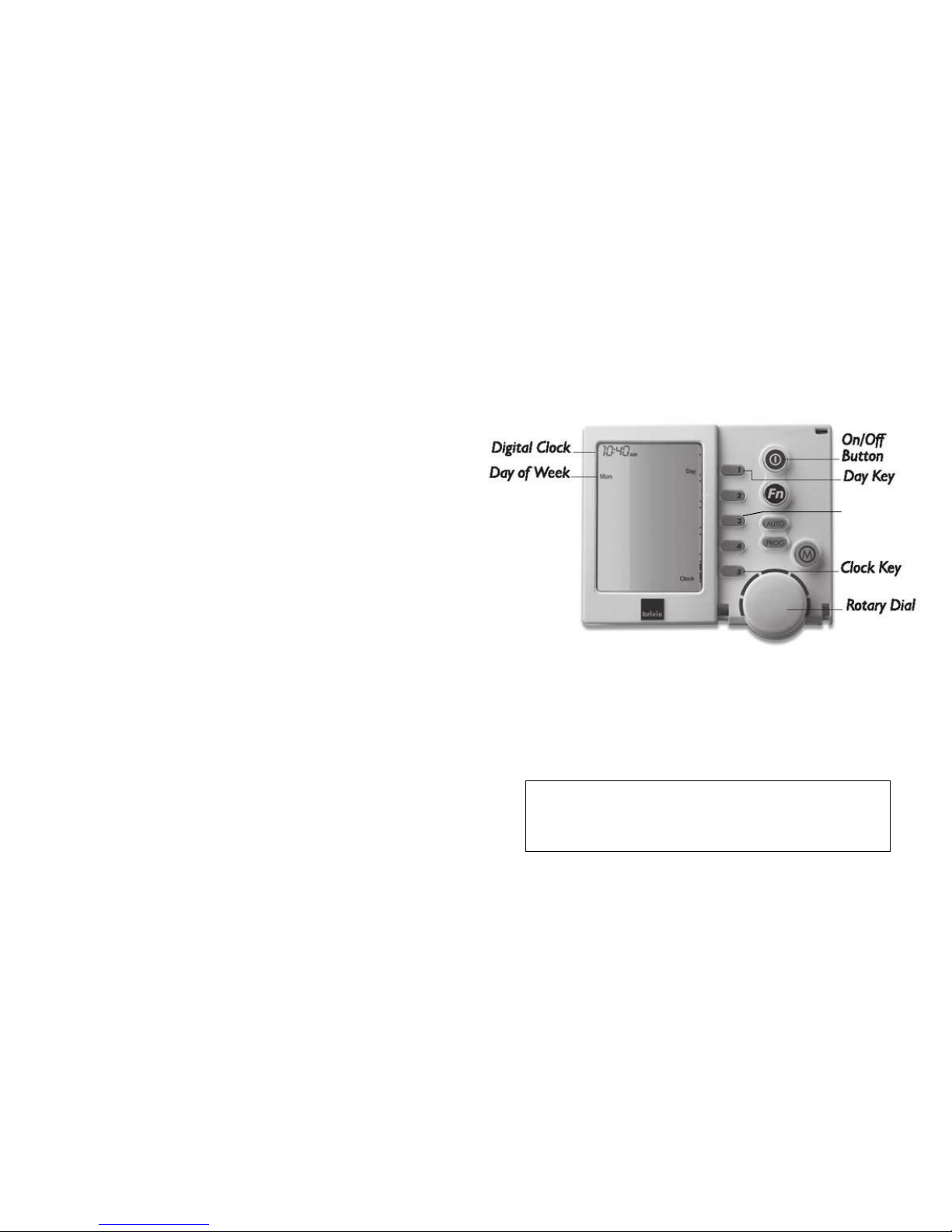
7.1 Setting the Time & Day
This is to be done at the Master Networker which displays the
word “Clock” opposite Key “5” or the Clock Key.
• Press the On/Off button to turn the System OFF.
• Press Key 5, Clock Key, and the screen will display the message
"Clock setting mode", and then the Digital Clock will flash
• Use the Rotary Dial to select the correct time.
• To set the day, press Key 1, the Day Key until the correct day of
the week appears on the left of the screen, e.g. "Mon".
• Press Key 5 the Clock Key again to save your new settings
Zone Cycle
Note: If multiple Brivis NC-6 Controllers are installed, only the
Master C
ontroller has the ability to set the clock time and day.
The Master control can be identified by the word "Clock" beside
Key “5”, when the ZonePlus system is in the OFF position.
Page 22

19
7.2 System Operation
Instruct home owner on system operation including:
• System design – MTSP or STSP
• Zone identification
• Minimum / maximum no. of simultaneous zones for design
conditions for Heating and Cooling (if fitted)
• Common Zone operation (if applicable)
• Constant Zone operation (if applicable)
• Operating the system (NC-6) manually
• Auto Operation – programming (NC-6) Comfort Schedule
Refer to ZonePlus Owner’s Manual for detailed instructions.
7.3 Product and Warranty Registration
Brivis recommends the registration of all products to ensure
efficient product support if and when required.
Please inform the home owner that product registration can be
completed:
• on-line at
brivis.com.au
• or via the registration form in the product Owner’s Manual
(i.e. Heater Owner’s Manual)
7.4 Service Notification Message
When the operating hours logged for an appliance exceeds the
predetermined period, the NC-6 displays the following
messages:
For Australia: (default: “ID73:1”)
“Fan run hours indicate it is time for a service call – For
assistance call 1300 BRIVIS”
For New Zealand: (
Change “ID73” from “1” to “2”)
“Fan run hours indicate it is time for a service call – For
assistance call 0800 427 484”
Refer to “n01 ID73:#”, Table 8 for details.
The ‘Spanner’ icon will flash once every second on the
NC-6 display. The owner can book a service call or clear the
spanner icon notification by pressing Key “4” on the Master
Controller.
7.5 ZonePlus Commissioning Information
Please ensure all system configuration and installer
parameters have been set and recorded in the ZonePlus
Installer’s Manual and the ZonePlus Owner’s Manual.
These should be left with the home owner for future reference
by the dealer or other service personnel.
8.0 Trouble Shooting Guide
General
• The Brivis NC-6 Networker comes with in-built diagnostics
to assist in determining the cause of a fault
• With some faults the system will attempt to automatically
restart, often several times
• Critical faults, where the equipment cannot automatically
restart, will require a service call
• Refer to the Troubleshooting section of the Brivis product
Installer Manual for specific equipment related issues
before calling for service
• Refer to ZonePlus Owner’s Manual Troubleshooting section
Page 23

20
ZonePlus Checklist
Correct system accessories and configuration for specific
heater dependent zone requirements (Table 2, p.6)
Correct wiring (5.2, p.7)
Correct Sensor ID set up (6.0, p.11)
Correct sequence of System Power Up (6.2, p.12)
Correct Heater Zoning Parameter set up (6.3, p.14)
Correct Networker Parameter set up (6.4, p.14)
No airflow
• Physically check zone motor to ensure mechanically sound
• Check wiring connection on the control board
Not enough airflow:
• Ensure the return air duct is not restricted or too small
• The supply air ductwork may be under sized or obstructed
• Ensure filter is not blocked
• If “ID105” and “ID111” (Refrigerated Cooling) are set to
“1” this will enable Fan Scaling.
• At this point you would have cycled though each zone
independently and set an appropriate flow rate
• If any changes after this point have been made to the
zoning configuration your Fan Scaling may have been reset.
You will need to reset your fan speeds for each zone, refer
to section 6.4.6 & 6.4.7, p.17
Airflow in wrong zone
• The incorrect sensor ID may have been assigned to the
wrong set of zoning parameters
• Check the polarity of the normally open (N/O) and normally
closed (N/C) damper motor wires at the heater control
board or 516 Zone Module
In MTSP conditions you cannot see the zone sensors on
the screen of the Master Controller; top right hand side
corner
• The zone sensor identification numbers may have been
reset to “1” if MTSP conditions were enabled at the end of
zoning parameter inputs
• Check the NT-1 jumper locations are in the correct position
• Each sensor must have a unique address. Press Key “3”
to access a sensor within the system. The sensor being
accessed will flash it’s LED once every second. Confirm
the sensor in question is in the correct zone – refer to
section 6.4.4, p.15
Blank screens when 2 or more NC-6s are installed:
Unit ID conflict between two Master NC-6 Controllers
Changing NC-6 unit ID
• With the NC-6 Slave user interface off the backing plate
hold down Keys “3” & “5” simultaneously
• Continue to hold Keys “3” & “5” and mount the interface to
the backing plate
• Do not release Key “3” & “5” for another five seconds.
• Eight large square blocks will appear at the top of the
screen during the reset
• Release Keys “3” & “5” and a message will scroll across
the screen “resetting this networker’s address!”
• After this message, “n00 ID00:0” will appear
• Rotate the dial to set the new NC-6 unit ID number (cannot
be “1”)
• Press the On/Off button to exit
Page 24
21
9.0 Appendix
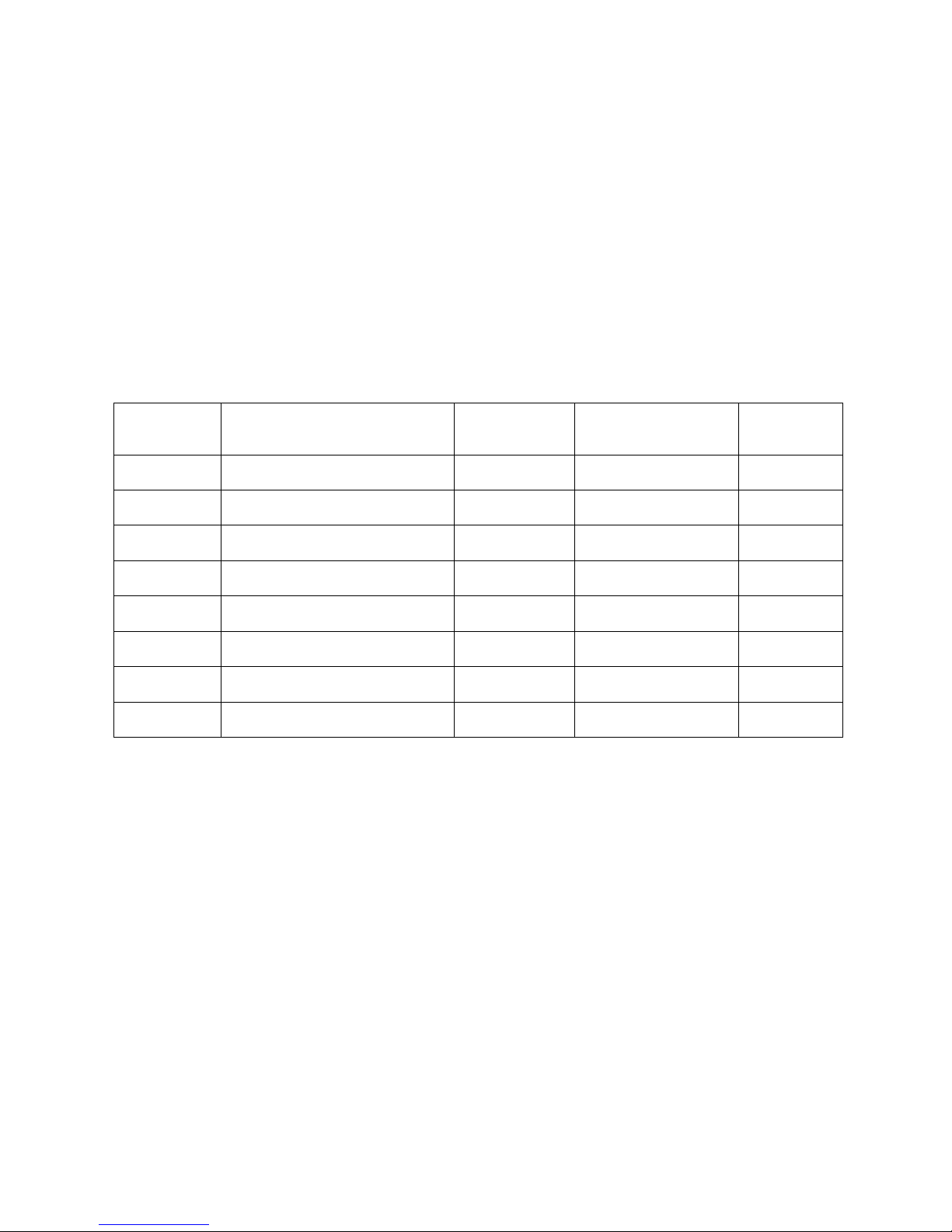
Table 7: Heater Installer Parameters
Parameter ID
Number and
Default Value
Installer Parameter Description
Installer Parameter
Value Settings
NOTE
Please record
the values you
have set
H01 ID01:1250
Maximum Heater fan speed setting,
500 - 1350 RPM Recommend “1350”
H01 ID02:1350
Maximum Cooling fan speed setting,
500 - 1350 RPM Recommend “1350”
H01 ID03:950
Minimum Heating fan speed setting,
500 - 1350 RPM Recommend “500”
H01 ID04:1 Heater “ID” number
1 “1” for single heater system
DO NOT
MODIFY
H01 ID05:500 Circulation fan speed
500 - 1350 RPM Recommend “500”
H01 ID06:45 Heater Supply air temperature (°C)
45 – 70°C Refer Heater Installer Manual
H01 ID07:0 The zoning configuration option
1 ,2, or 5 Refer Table 2, p.6
H01 ID08:1000 Minimum Cooling fan speed
1000 RPM
Do not set below “1000”
(75% of 1350 RPM)
Page 25
22
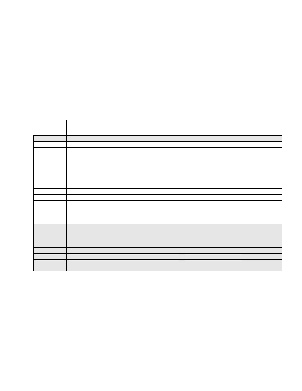
Table 8: Master Controller Parameters
Parameter ID
Number and
Value (default)
Installer Parameter Description Installer Parameter
Value Settings
Please record
the values you
have set
n01 ID00:0 Networker Address or Number Master = 1; Slave ≥ 2
n01 ID01:1 Refrig Common Zone - Enable Refrig/Heater ID No.
n01 ID02:1 Refrig Common Zone - Temperature Sensing ID No. Sensor No. 1 to 4
n01 ID03:0 Refrig Zone A - Unit Refrig/Heater ID No.
n01 ID04:0 Refrig Zone A - Relay Relay No. 1 to 4
n01 ID05:1 Refrig Zone A - Temperature Sensing ID No. Sensor No. 1 to 4
n01 ID06:0 Refrig Zone B - Unit Refrig/Heater ID No.
n01 ID07:2 Refrig Zone B - Relay Relay No. 1 to 4
n01 ID08:1 Refrig Zone B - Temperature Sensing ID No. Sensor No. 1 to 4
n01 ID09:0 Refrig Zone C - Unit Refrig/Heater ID No.
n01 ID10:3 Refrig Zone C - Relay Relay No. 1 to 4
n01 ID11:1 Refrig Zone C - Temperature Sensing ID No. Sensor No. 1 to 4
n01 ID12:0 Refrig Zone D - Unit Refrig/Heater ID No.
n01 ID13:4 Refrig Zone D - Relay Relay No. 1 to 4
n01 ID14:1 Refrig Zone D - Temperature Sensing ID No. Sensor No. 1 to 4
n01 ID15:1 Heating Common Zone - Enable Heater ID No.
n01 ID16:1 Heating Common Zone - Temperature Sensing ID No. Sensor No. 1 to 4
n01 ID17:0 Heating Zone A - Unit Heater ID No.
n01 ID18:1 Heating Zone A - Relay Relay No. 1 to 4
n01 ID19:1 Heating Zone A - Temperature Sensing ID No. Sensor No. 1 to 4
n01 ID20:0 Heating Zone B - Unit Heater ID No.
n01 ID21:2 Heating Zone B - Relay Relay No. 1 to 4
n01 ID22:1 Heating Zone B - Temperature Sensing ID No. Sensor No. 1 to 4
Page 26
23
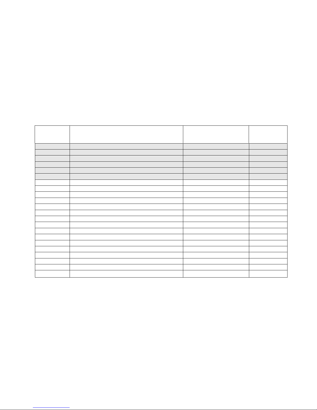
Table 8: Master Controller Parameters Cont’d
Parameter ID
Number and
Value (default)
Installer Parameter Description Installer Parameter
Value Settings
Please record
the values you
have set
n01 ID23:0 Heating Zone C - Unit Heater ID No.
n01 ID24:3 Heating Zone C - Relay Relay No. 1 to 4
n01 ID25:1 Heating Zone C - Temperature Sensing ID No. Sensor No. 1 to 4
n01 ID26:0 Heating Zone D - Unit Heater ID No.
n01 ID27:4 Heating Zone D - Relay Relay No. 1 to 4
n01 ID28:1 Heating Zone D - Temperature Sensing ID No. Sensor No. 1 to 4
n01 ID43:0 Heating - OFF Cycle Circulation Fan Operation 0 = OFF; 1 = ON
n01 ID73:1 Equipment Service Notification Message 0 = OFF; 1 = AUST; 2 = NZ
n01 ID92:0 Multi Set Point Control - Enable 0 = OFF; 1 = ON
n01 ID93:1 Refrig - Cooling Zone to Force Open 0 = None; 1=A; 2=B; 3=C; 4=D
n01 ID105:0 Heating - Enable Fan Scaling 0 = OFF; 1 = ON
n01 ID106:1 Heating - Common Zone Fan Speed Range = 1 to 16
n01 ID107:1 Heating - Zone A Fan Speed Range = 1 to 16
n01 ID108:1 Heating - Zone B Fan Speed Range = 1 to 16
n01 ID109:1 Heating - Zone C Fan Speed Range = 1 to 16
n01 ID110:1 Heating - Zone D Fan Speed Range = 1 to 16
n01 ID111:0 Refrig - Enable Fan Scaling 0 = OFF; 1 = ON
n01 ID112:1 Refrig - Common Zone Fan Speed Range = 1 to 16
n01 ID113:1 Refrig - Zone A Fan Speed Range = 1 to 16
n01 ID114:1 Refrig - Zone B Fan Speed Range = 1 to 16
n01 ID115:1 Refrig - Zone C Fan Speed Range = 1 to 16
n01 ID116:1 Refrig - Zone D Fan Speed Range = 1 to 16
Page 27
24
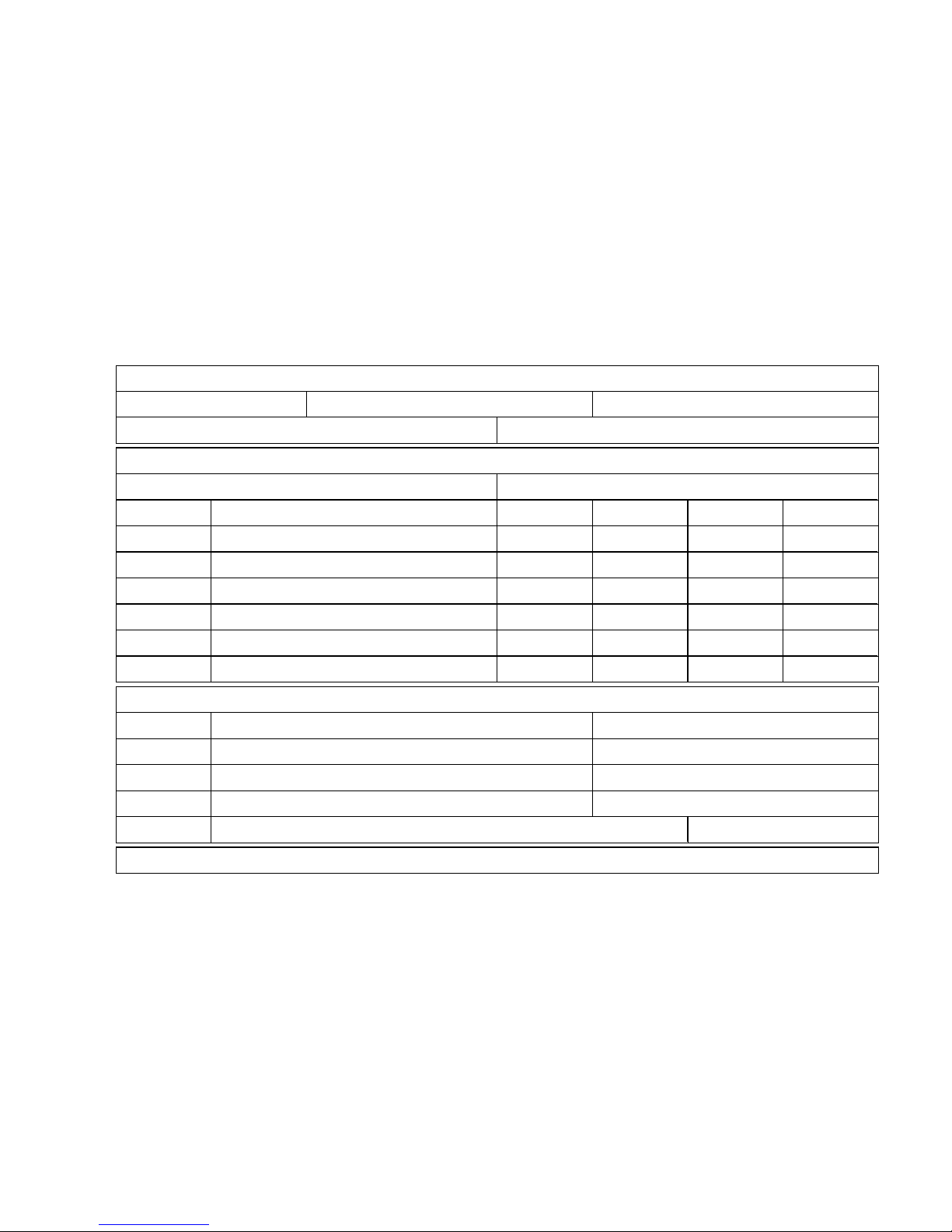
Table 9: Home Owner System Information
ZONE
SENSOR TYPE
(NC-6 / NT-1)
SENSOR ID
(n01 - n04)
HEAT FAN SETTING
(1-16)
COOL FAN SETTING
(1-16)
ZONE A
ZONE B
ZONE C
ZONE D
COMMON
(STSP - If applic)
--
CONSTANT
(MTSP - If applic)
-- -- -- --
HEATER Serial No.
ICE OUTDOOR Serial No.
ICE INDOOR Serial No.
EVAPORATIVE
COOLER
Serial No.
BRIVIS DEALER Tel:
ZonePlus SYSTEM CONFIGURATION
HEATING ONLY
DUAL COMFORT
HEATING & EVAPORATIVE COOLING^
MULTI TEMPERATURE SET POINT (MTSP)
SINGLE TEMPERATURE SET POINT (STSP)
SYSTEM DESIGN CONDITIONS & PARAMETERS
Maximum no. of Zones for HEATING: Maximum no. of Zones for REFRIGERATED COOLING:
Installation
Date:
Model No.
Model No.
ZONE: A B C D NIL
(circle one only)
Model No.
^
Zoning is not available during Evaporative Cooling mode
EQUIPMENT DETAILS
Model No.
ROOM(S)
INSTALLER: Please complete this information and have Home Owner retain for future reference , alternatively complete this table in the Brivis ZonePlus Home O wner's Manual.
Page 28
25
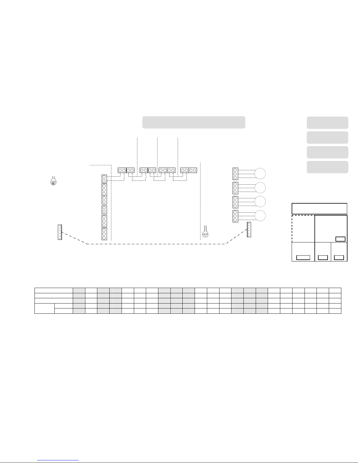
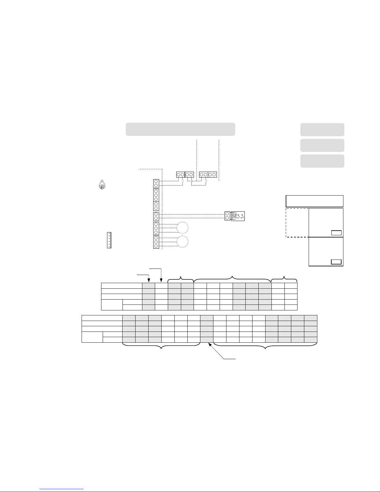
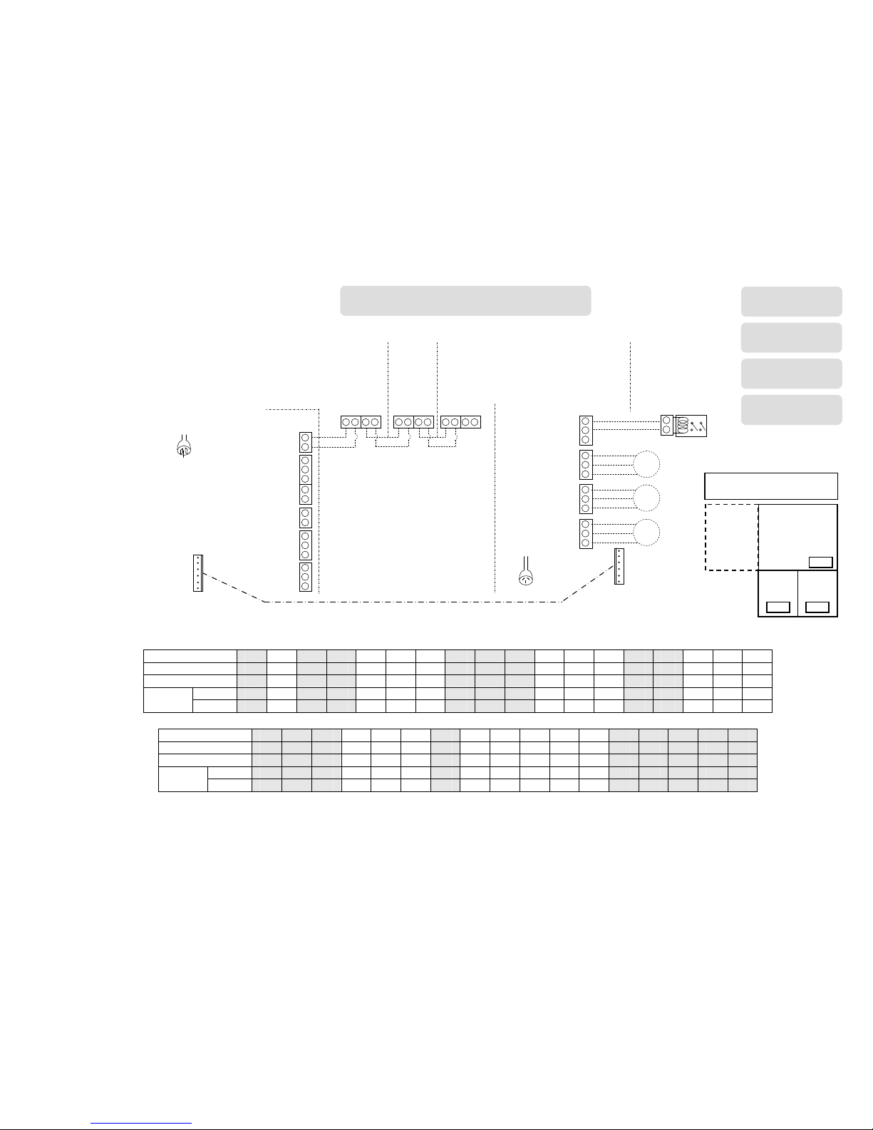
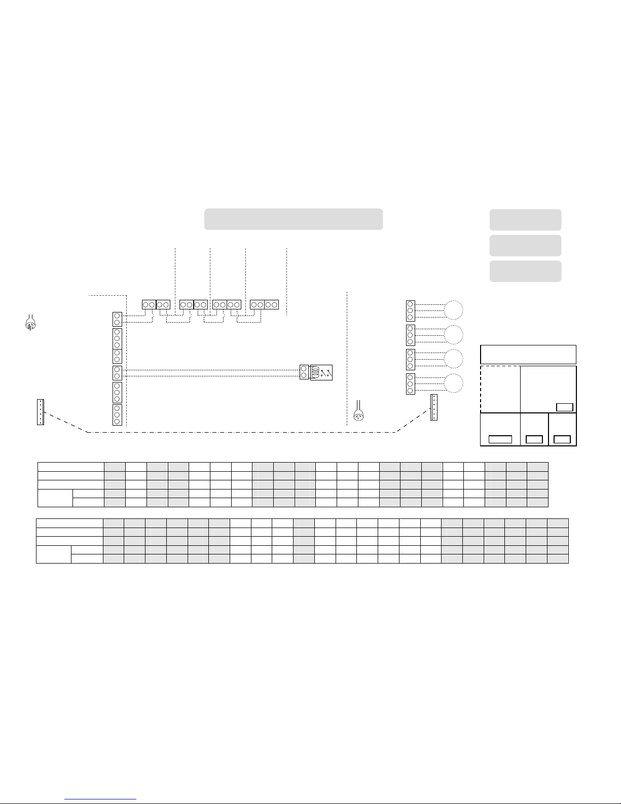
Sample System Configuration Diagrams
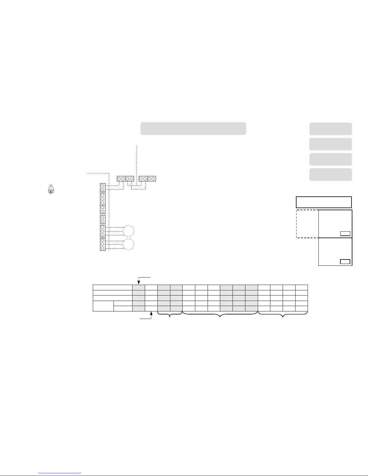
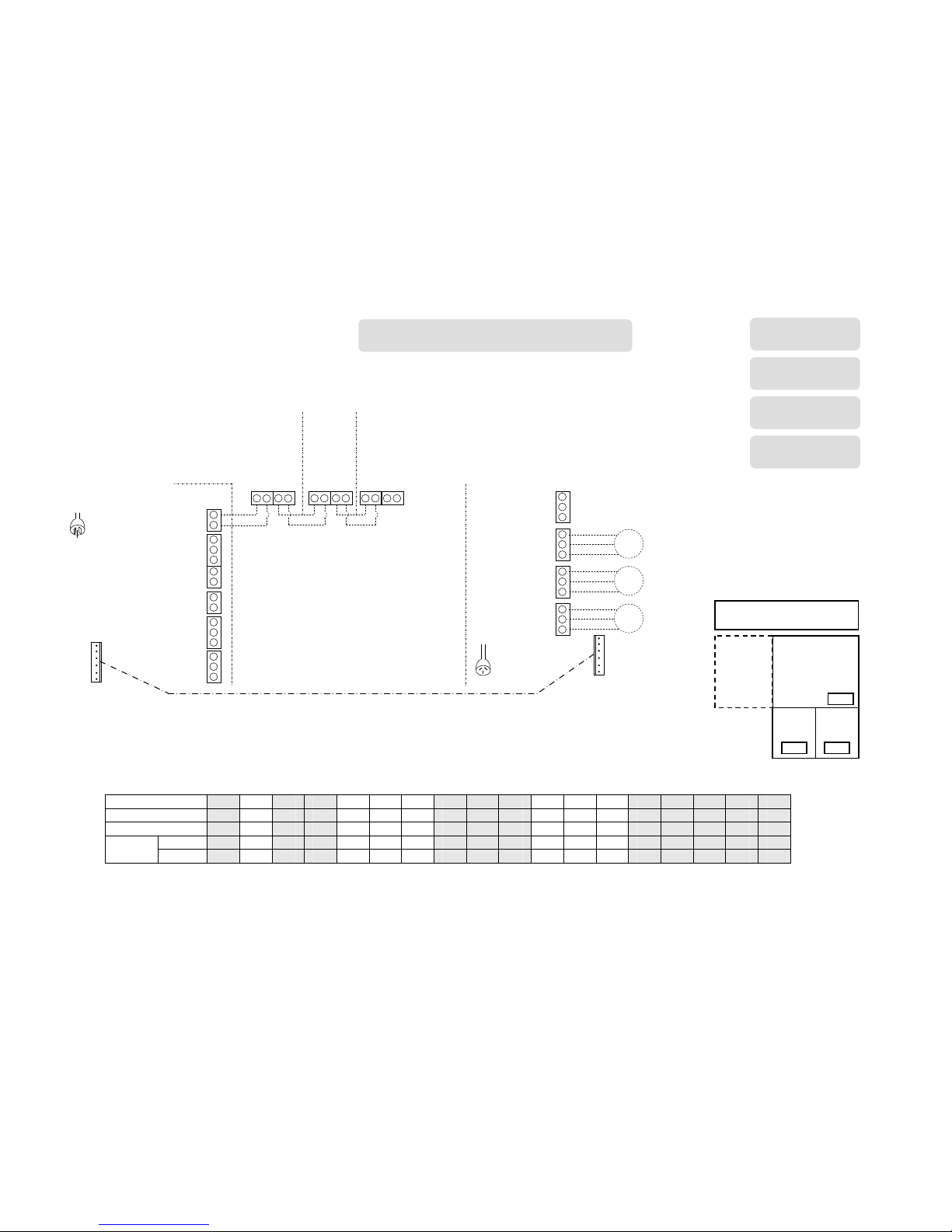
Below are six example circuit diagrams detailing the required
parameter values for Multi Temperature Set Point (MTSP)
and Single Temperature Set Point (STSP) system
configurations.
Please Note:
All MTSP circuit diagrams have:
“ID92:1” - MTSP configuration ENABLED
“ID15” - Heating Common Zone DISABLED
“ID01” - Cooling Common Zone DISABLED
“ID105:1” - Heating Fan Scaling ENABLED
“ID111:1” - Cooling Fan Scaling ENABLED
“ID93:1” - Cooling Constant Zone ENABLED (‘1’ = Zone A)
All STSP circuit diagrams have:
“ID92:0” - STSP configuration ENABLED
“ID15:1” - Heating Common Zone ENABLED
“ID01:1” - Cooling Common zone ENABLED
“ID105:1” - Heating Fan Scaling ENABLED
“ID111:1” - Cooling Fan Scaling ENABLED
“ID93” - Cooling Constant Zone DISABLED
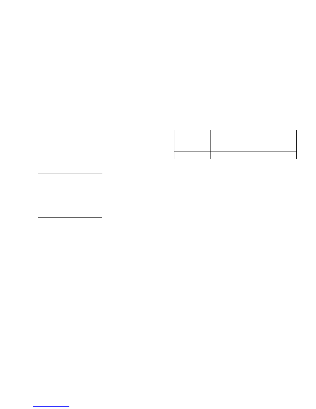
Table 10: Sample Circuit Diagrams Reference
NO. OF ZONES HEATING ONLY DUAL COMFORT
2 Page 26 Page 29
3
Page 27 Page 30
4
Page 28 Page 31
Page 29
26
STEP
1 2 3 4 5 6 7 8 9 10 11 12 13 14
UNIT ID H01 n01 n01 n01 n01 n01 n01 n01 n01 n01 n01 n01 n01 n01
PARAMETER No:
ID07 ID92 ID15 ID16 ID17 ID18 ID19 ID20 ID21 ID22 ID105 ID106 ID107 ID108
MTSP 1 1
n/a
n/a 1 1 1 1 2 2
1
n/a 1-16 1-16
VALUE
STSP 1 0
1
1 1 1 1 1 2 2
1
1-16 1-16 1-16
2 x 24VAC POWER
OPEN / POWER
CLOSE DAMPER
MOTORS
HEATER
CONTROL BOARD
240VAC
TO HEATER
N/C
0V
N/O
ZONE B
N/C
0V
N/O
ZONE A
Y
C
G
W
R
TW2
N/O
0V
ZONE C/
ADD-ON
TW1
TW2
TW1
TW2
NC-6
MASTER
ZONE A
TW1
TW2
TW1
TW2
NT-1
SENSOR
ZONE B
HEATING ONLY 2 ZONES
HEATER
SP SERIES
HX SERIES
MX SERIES
Fan Scaling
Refer to section 6.3
Heating Zone
Parameters
Refer to section 6.4.1
Heating C/Zone
Parameters
Common
A
NC-6
B
NT-1
Home Schematic
Page 30
27
STEP
1 2 3 4 5 6 7 8 9 10 11 12 13 14 15 16 17 18
UNIT ID H01 n01 n01 n01 n01 n01 n01 n01 n01 n01 n01 n01 n01 n01 n01 n01 n01 n01
PARAMETER No:
ID07 ID92 ID15 ID16 ID17 ID18 ID19 ID20 ID21 ID22 ID23 ID24 ID25 ID105 ID106 ID107 ID108 ID109
MTSP 1 1
n/a
n/a 1 1 1 1 2 2 1 3 3
1
n/a 1-16 1-16 1-16
VALUE
STSP 1 0
1
1 1 1 1 1 2 2 1 3 3
1
1-16 1-16 1-16 1-16
HEATER CONTROL
BOARD
TW1
N/C
0V
N/O
ZONE B
N/C
0V
N/O
ZONE A
Y
C
G
W
R
TW2
N/O
0V
ZONE C/
ADD-ON
EXT ZONE
MODULE
240VAC
TO HEATER
240VAC
TO 516
MODULE
NET516 LOW VOLTAGE
ZONE MODULE
N/C
0V
N/O
ZONE D
REFRIG
N/C
0V
N/O
ZONE C
N/C
0V
N/O
ZONE A
N/C
0V
N/O
ZONE B
HEATER
CONNECT
3 x 24VAC POWER
OPEN / POWER
CLOSE DAMPER
MOTORS
OPEN
COMMON
CLOSE
LOOM SUPPLIED
TW1
TW2
TW1
TW2
NC-6
MASTER
ZONE A
TW1
TW2
TW1
TW2
NT-1
SENSOR
ZONE B
TW1
TW2
TW1
TW2
NT-1
SENSOR
ZONE C
HEATING ONLY 3 ZONES
HEATER
SP SERIES
HX SERIES
MX SERIES
A
NC-6
C
NT-1
B
NT-1
Common
Home Schematic
Page 31
28
STEP
1 2 3 4 5 6 7 8 9 10 11 12 13 14 15 16 17 18 19 20 21 22
UNIT ID H01 n01 n01 n01 n01 n01 n01 n01 n01 n01 n01 n01 n01 n01 n01 n01 n01 n01 n01 n01 n01 n01
PARAMETER No:
ID07 ID92 ID15 ID16 ID17 ID18 ID19 ID20 ID21 ID22 ID23 ID24 ID25 ID26 ID27 ID28 ID105 ID106 ID107 ID108 ID109 ID110
MTSP 1 1
n/a
n/a 1 1 1 1 2 2 1 3 3 1 4 4
1
n/a 1-16 1-16 1-16 1-16
VALUE
STSP 1 0
1
1 1 1 1 1 2 2 1 3 3 1 4 4
1
1-16 1-16 1-16 1-16 1-16
HEATER CONTROL
BOARD
TW1
N/C
0V
N/O
ZONE B
N/C
0V
N/O
ZONE A
Y
C
G
W
R
TW2
N/O
0V
ZONE C/
ADD-ON
EXT ZONE
MODULE
240VAC
TO HEATER
NET516 LOW VOLTAGE
ZONE MODULE
240VAC
TO 516
MODULE
24VAC POWER
OPEN / POWER
CLOSE DAMPER
MOTOR
CLOSE
COMMON
OPEN
N/C
0V
N/O
ZONE D
REFRIG
N/C
0V
N/O
ZONE C
N/C
0V
N/O
ZONE A
N/C
0V
N/O
ZONE B
HEATER
CONNECT
LOOM SUPPLIED
NC-6
MASTER
ZONE A
TW1
TW2
TW1
TW2
NT-1
SENSOR
ZONE D
TW1
TW2
TW1
TW2
NT-1
SENSOR
ZONE C
TW1
TW2
TW1
TW2
NT-1
SENSOR
ZONE B
TW1
TW2
TW1
TW2
HEATING ONLY 4 ZONES
HEATER
SP SERIES
HX SERIES
MX SERIES
A
NC-6
D
NT-1
C
NT-1
B
NT-1
Common
Home Schematic
Page 32
29
STEP
1 2 3 4 5 6 7 8 9 10 11 12
UNIT ID H01 n01 n01 n01 n01 n01 n01 n01 n01 n01 n01 n01
PARAMETER No:
ID07 ID92 ID01 ID02 ID03 ID04 ID05 ID06 ID07 ID08 ID15 ID16
MTSP 5 1 n/a n/a 1 1 1 1 2 2 n/a n/a
VALUE
STSP 5 0 1 1 1 1 1 1 2 2 1 1
STEP 13 14 15 16 17 18 19 20 21 22 23 24 25 26
27
UNIT ID n01 n01 n01 n01 n01 n01 n01 n01 n01 n01 N01 n01 n01 n01
n01
PARAMETER No:
ID17 ID18 ID19 ID20 ID21 ID22 ID93 ID105
ID106
ID107 ID108 ID111 ID112 ID113
ID114
MTSP 1 1 1 1 2 2 1
1
n/a 1-16 1-16
1
n/a 1-16 1-16
VALUE
STSP 1 1 1 1 2 2 n/a
1
1-16 1-16 1-16
1
1-16 1-16 1-16
HEATER CONTROL
BOARD
TW1
N/C
0V
N/O
ZONE B
N/C
0V
N/O
ZONE A
Y
C
G
W
R
TW2
N/O
0V
ZONE C/
ADD-ON
EXT ZONE
MODULE
240VAC
TO HEATER
ADD-ON
CONTROL
BOARD RELAY
NC-6
MASTER
ZONE A
TW1
TW2
TW1
TW2
NT-1
SENSOR
ZONE B
TW1
TW2
TW1
TW2
2 x 24VAC POWER
OPEN / POWER
CLOSE DAMPER
MOTORS
DUAL COMFORT 2 ZONES
HEATER
HX SERIES
MX SERIES
Heating C/Zone
Parameters
Cooling Zone
Parameters
Fan Scaling
Refer to section 6.4.3
Refer to section 6.3
Heating Zone Parameters
Refer to section 6.4.1
Cooling C/Zone
Parameters
Common
A
NC-6
B
NT-1
Home Schematic
Page 33
30
STEP
19 20 21 22 23 24 25 26
27
28 29
30
31 32 33 34
35
UNIT ID n01 n01 n01 n01 n01 n01 n01 n01 n01 n01 n01 n01 n01 n01 n01 n01 n01
PARAMETER No:
ID20 ID21 ID22 ID23 ID24 ID25 ID93 ID105
ID106
ID107 ID108 ID109 ID111 ID112 ID113 ID114 ID115
MTSP 1 2 2 1 3 3 1
1
n/a 1-16 1-16 1-16
1
n/a 1-16 1-16 1-16
VALUE
STSP 1 2 2 1 3 3 n/a
1
1-16 1-16 1-16 1-16
1
1-16 1-16 1-16 1-16
STEP 1 2 3 4 5 6 7 8 9 10 11 12 13 14 15 16 17 18
UNIT ID H01 n01 n01 n01 n01 n01 n01 n01 n01 n01 n01 n01 n01 n01 n01 n01 n01 n01
PARAMETER No:
ID07 ID92 ID01 ID02 ID03 ID04 ID05 ID06 ID07 ID08 ID09 ID10 ID11 ID15 ID16 ID17 ID18 ID19
MTSP 2 1 n/a n/a 1 1 1 1 2 2 1 3 3 n/a n/a 1 1 1
VALUE
STSP 2 0 1 1 1 1 1 1 2 2 1 3 3 1 1 1 1 1
DUAL COMFORT 3 ZONES
HEATER
SP SERIES
HX SERIES
MX SERIES
ADD-ON
CONTROL
BOARD RELAY
LOOM SUPPLIED
HEATER CONTROL
BOARD
TW1
N/C
0V
N/O
ZONE B
N/C
0V
N/O
ZONE A
Y
C
G
W
R
TW2
N/O
0V
ZONE C/
ADD-ON
EXT ZONE
MODULE
240VAC
TO HEATER
NC-6
MASTER
ZONE A
TW1
TW2
TW1
TW2
NT-1
SENSOR
ZONE C
TW1
TW2
TW1
TW2
NT-1
SENSOR
ZONE B
TW1
TW2
TW1
TW2
NET516 LOW VOLTAGE
ZONE MODULE
240VAC
TO 516
MODULE
N/C
0V
N/O
ZONE D
REFRIG
N/C
0V
N/O
ZONE C
N/C
0V
N/O
ZONE A
N/C
0V
N/O
ZONE B
HEATER
CONNECT
OPEN
COMMON
CLOSE
A
NC-6
C
NT-1
B
NT-1
Common
Home Schematic
Page 34
31
STEP
22 22 22 22 26
27
28 29
30
31 32 33 34
35
36
37
38
39
40 41
42 43
UNIT ID n01 n01 n01 n01 n01 n01 n01 n01 n01 n01 n01 n01 n01 n01 n01 n01 n01 n01 n01 n01 n01 n01
PARAMETER No:
ID20 ID21 ID22 ID23 ID24 ID25 ID26 ID27 ID28 ID93 ID105
ID106
ID107 ID108 ID109 ID109 ID111 ID112 ID113 ID114 ID115 ID116
MTSP 1 2
2 1
3 3 1 4 4 1
1
n/a 1-16 1-16 1-16 1-16
1
n/a 1-16 1-16 1-16 1-16
VALUE
STSP 1 2
2 1
3 3 1 4 4 n/a
1
1-16 1-16 1-16 1-16 1-16
1
1-16 1-16 1-16 1-16 1-16
STEP 1 2 3 4 5 6 7 8 9 10 11 12 13 14 15 16 17 18 19 20 21
UNIT ID H01 n01 n01 n01 n01 n01 n01 n01 n01 n01 n01 n01 n01 n01 n01 n01 n01 n01 n01 n01 n01
PARAMETER No:
ID07 ID92 ID01 ID02 ID03 ID04 ID05 ID06 ID07 ID08 ID09 ID10 ID11 ID12 ID13 ID14 ID15 ID16 ID17 ID18 ID19
MTSP 5 1 n/a n/a 1 1 1 1 2 2 1 3 3 1 4 4 n/a n/a 1 1 1
VALUE
STSP 5 0 1 1 1 1 1 1 2 2 1 3 3 1 4 4 1 1 1 1 1
LOOM SUPPLIED
240VAC
TO 516
MODULE
NET516 LOW VOLTAGE
ZONE MODULE
24VAC POWER
OPEN / POWER
CLOSE DAMPER
MOTOR
CLOSE
COMMON
OPEN
N/C
0V
N/O
ZONE D
REFRIG
N/C
0V
N/O
ZONE C
N/C
0V
N/O
ZONE A
N/C
0V
N/O
ZONE B
HEATER
CONNECT
HEATER CONTROL
BOARD
TW1
N/C
0V
N/O
ZONE B
N/C
0V
N/O
ZONE A
Y
C
G
W
R
TW2
N/O
0V
ZONE C/
ADD-ON
EXT ZONE
MODULE
240VAC
TO HEATER
ADD-ON
CONTROL
BOARD RELAY
NC-6
MASTER
ZONE A
TW1
TW2
TW1
TW2
NT-1
SENSOR
ZONE D
TW1
TW2
TW1
TW2
NT-1
SENSOR
ZONE C
TW1
TW2
TW1
TW2
NT-1
SENSOR
ZONE B
TW1
TW2
TW1
TW2
DUAL COMFORT 4 ZONES
HEATER
HX SERIES
MX SERIES
A
NC-6
D
NT-1
C
NT-1
B
NT-1
Common
Home Schematic
Page 35

32
Notes:
Page 36
33
Part Number: B061016
July 2013
Brivis Climate System Pty Ltd
ABN 64 096 079 088
AU 24752
© Brivis Climate Systems Pty. Ltd. 2013.
All rights reserved. No part of these documents may be used in any way or form without prior written consent from Brivis Climate Systems Pty Ltd.
Brivis Australia
61 Malcolm Rd
Braeside Victoria 3195
Australia
1300 BRIVIS (1300 274 847)
Fax: +61 (03) 9264 9400
www.brivis.com.au
email: [email protected]
Brivis New Zealand
Distributor: Warm Air Ltd
69 Marsden Street
Lower Hutt 5010 New Zealand
PO Box 38523
Wellington Mail Centre
Wellington 5043 New Zealand
0800 WARMAIR (0800 9276 247)
Ph: +64 (04) 920 1670
Fax: +64(04) 920 1681
www.warmair.co.nz
email: [email protected]
Brivis South Africa
Distributor: Lorenz and Associates
Northlands Deco Park
Cnr Witkoppen and Newmarket Roads
North Riding, Johannesburg South Africa 2194
0861 BRIVIS (0861 274 847)
Ph: +27 (011) 704 6112
Fax: +27 (011) 704 0022
www.brivis.co.za
email: [email protected]
For all your Sales and Service enquiries call us on 1300 BRIVIS (1300 274 847)
www.brivis.com.au
 Loading...