

Page 1
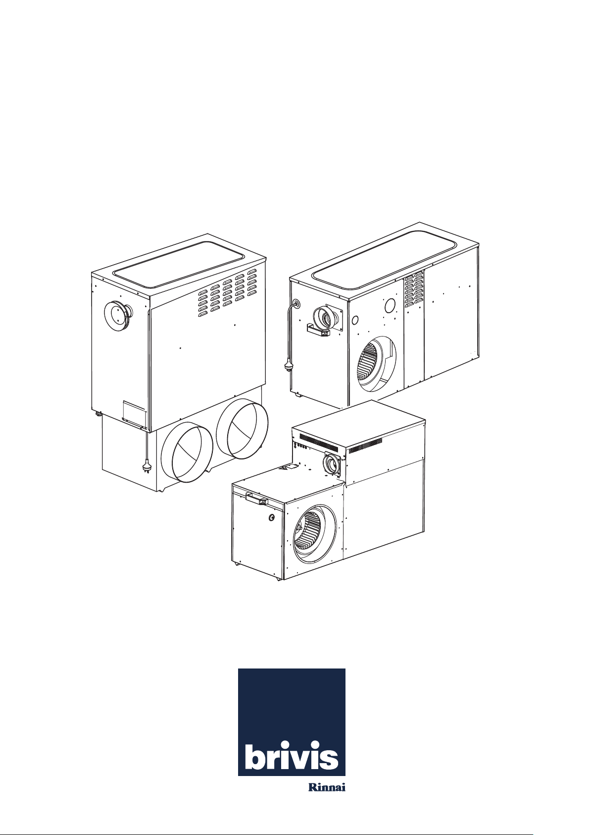
Brivis StarPro
by
Ducted Gas Heater
Installation Manual
SP623 UN
BX5
PLEASE READ THESE INSTRUCTIONS CAREFULLY
BEFORE INSTALLING THIS PRODUCT
SP521IN
Page 2

This page is intentionally blank
Rinnai 2 Ducted Gas Heater IM
Page 3

Table of Contents
Warnings and Important Information 5
1. Scope 7
1.1 SP Heater Overview......................................................................................................................................... 7
1.2 BX5 Heater Overview....................................................................................................................................... 7
1.3 Installer Due Diligence for Changeovers ......................................................................................................... 8
Definitions ................................................................................................................................................................... 8
Disclaimer ................................................................................................................................................................... 8
2. General Product Guidelines 9
2.1 Application and Sizing ...................................................................................................................................... 9
2.2 Inspection ......................................................................................................................................................... 9
2.3 Unpacking the Heater ...................................................................................................................................... 9
2.4 Unloading or Lifting the Heater ........................................................................................................................ 9
2.5 Service Connection Guidelines ...................................................................................................................... 10
2.5.1 Gas Inlet Connection ......................................................................................................................... 10
2.5.2 Electrical Power Supply ..................................................................................................................... 10
3. Heater Dimensions and Clearances 11
3.1 Heater Dimensions – SP4, SP5 and SP6 ...................................................................................................... 11
3.2 Heater Dimensions – BX5 .............................................................................................................................. 12
3.3 Service Clearances – Internal ........................................................................................................................ 13
3.3.1 Service Clearance Notes ................................................................................................................... 13
3.3.2 Internal Clearances ............................................................................................................................ 13
3.4 Service Clearances – External ....................................................................................................................... 14
3.4.1 Installation of Flashing ....................................................................................................................... 14
3.4.2 SP4, SP5 and SP6 External Clearances ........................................................................................... 14
3.4.3 BX5 Service Clearances .................................................................................................................... 15
4. Heater Configuration 16
4.1 Heater Duct Pop Installation .......................................................................................................................... 16
4.2 Duct Connection Configuration Options ......................................................................................................... 16
Return Air Orientation............................................................................................................................................... 17
4.2.1 SP430U and SP435U Fan Cabinet: Swap F1 – F2 .......................................................................... 17
4.2.2 SP415U, SP421U Fan Cabinet: Swap F1/F2 – F3 ........................................................................... 17
4.2.3 SP5U and SP6U Fan Cabinet: Swap F1 – F2 .................................................................................. 17
4.2.4 SP5U and SP6U Fan Cabinet: Swap F1/F2 – F3 ............................................................................. 17
4.2.5 SP5 and SP6 Internal Fan Cabinet: Swap F1 – F2/F3 ..................................................................... 17
Supply Air Orientation .............................................................................................................................................. 18
4.2.6 SP4 Heater Cabinet: Swap H1/H2 – H3 ............................................................................................ 18
4.2.7 SP5 and SP6 Heater Cabinet: Swap Any Combination of H1, H2 or H3 .......................................... 18
Supply Air Switch Position – SP623U/630U/521U ................................................................................................... 18
4.2.8 Supply Air Switch Position ................................................................................................................. 18
4.3 SP Series Gas Feed Tube Installation ........................................................................................................... 19
5. Condensate Removal 20
5.1 Condensate Drain .......................................................................................................................................... 20
5.1.1 Install a Condensate Drain to an SP6 Universal and Internal Units .................................................. 20
6. Heater Positioning 21
6.1 Wall Cut-out Area ........................................................................................................................................... 21
6.2 Splitting Heater for Assisted Lifting and Positioning ...................................................................................... 21
6.2.1 SP4 Universal Heater ........................................................................................................................ 21
6.2.2 SP5 Universal Heater ........................................................................................................................ 22
6.2.3 SP5 and SP6 Internal Heater ............................................................................................................ 22
6.2.4 SP6 Universal Heater ........................................................................................................................ 22
Rinnai 3 Ducted Gas Heater IM
Page 4

6.3 Internal Installations ....................................................................................................................................... 23
6.3.1 Installation in the Roof Space ............................................................................................................ 23
6.3.2 Installation Beneath the Floor ............................................................................................................ 23
6.3.3 Ventilation Calculations ...................................................................................................................... 23
6.4 External Installations ...................................................................................................................................... 24
6.4.1 SP4 – Installation of Flashing ............................................................................................................ 25
6.4.2 SP5 and SP6 – Installation of Flashing ............................................................................................ 25
7. Flue Instructions and Clearances 26
7.1 Internal – SP Series ....................................................................................................................................... 26
7.1.1 General .............................................................................................................................................. 26
7.1.2 SP4 and SP5 Models – 100mm Non-corrosive Metal Flue. .............................................................. 26
7.1.3 SP6 Universal Models – 100mm Drainage Waste Vent (DWV) Flue ................................................ 26
7.1.4 Remote Terminal (Part No. B018384) Internal Model Applications ................................................... 27
7.2 External – SP Series Flue Terminal Clearances ........................................................................................... 28
7.2.1 Installation of Flue Terminal ............................................................................................................... 28
7.3 External – BX5 Flue Terminal Clearances ..................................................................................................... 29
8. Thermistor Installation 30
8.1 SP Series Thermistor Installation ................................................................................................................... 30
8.2 BX5 Thermistor Installation ............................................................................................................................ 30
9. Ducting and Outlets 32
9.2 Return Air Grille.............................................................................................................................................. 32
9.3 Return Air Pop Configuration Changes ......................................................................................................... 32
9.4 Outlet Chart Information ................................................................................................................................. 33
10. Thermostat Installation 35
10.1 SP and BX5 Series Thermostat Positioning Guidelines ................................................................................ 35
10.2 Programmable and Manual Thermostat Installation ...................................................................................... 35
10.2.1 Connect a Programmable Thermostat ............................................................................................... 35
10.2.2 Connect a Manual Thermostat .......................................................................................................... 36
11. Networker Installation: Single and Multiple Connections 38
11.1 Networker Installation ..................................................................................................................................... 38
11.2 Connect a Networker to SP or BX5 Series Heaters ...................................................................................... 38
11.3 Connect a Networker to a BX5 Heater .......................................................................................................... 38
11.3.1 Connect Multiple Heaters to a Networker .......................................................................................... 39
11.3.2 Connect Dual Networkers .................................................................................................................. 39
11.3.3 Change a Networker from Slave to Master ....................................................................................... 40
11.3.4 Network 516 Manual .......................................................................................................................... 40
11.3.5 ZonePlus ............................................................................................................................................ 40
12. Adaptive Zoning and Add-on Air Conditioning 41
12.1 Options ........................................................................................................................................................... 41
12.2 Damper Motor Connections ........................................................................................................................... 41
12.3 Connect a Damper Motor to the Control Module ........................................................................................... 42
13. Commissioning and Control Settings 43
13.1 SP4, SP5, SP6 and BX5 Heater Control Settings ......................................................................................... 43
13.2 SP4, SP5, SP6 and BX5 Commissioning Instructions .................................................................................. 45
13.2.1 Initial Damper Settings ....................................................................................................................... 45
13.2.2 Initial Ignition and Gas Inlet Pressure Check .................................................................................... 45
13.2.3 Heater Temperature Settings and Fan Speed ................................................................................... 45
13.3 Final Checks (SP4, SP5, SP6 and BX5 Heaters) .......................................................................................... 47
13.4 Fault Code Identification on Heater PCB ....................................................................................................... 47
14. Technical Specifications 49
Rinnai 4 Ducted Gas Heater IM
Page 5
WARNING
WARNING
NOTE
WARNINGS AND IMPORTANT INFORMATION
READ ALL INSTRUCTIONS BEFORE USING THE APPLIANCE.
Always comply with the following precautions to avoid dangerous situations and to ensure
optimum performance.
Failure to carefully read and follow all instructions in this manual can result in equipment
malfunction, property damage, personal injury and/or death.
DANGER: Indicates an imminently hazardous situation which, if not avoided, will result in
personal injury or death.
WARNINGS: Indicates a potentially hazardous situation which, if not avoided, could result in
personal injury or death.
CAUTIONS: Indicates a potentially hazardous situation which, if not avoided, could result in
minor or moderate injury or damage to the appliance. It may also be used to alert against unsafe
practices.
REGULATORY / INSTALLATION
This appliance shall be installed in accordance with:
• Manufacturer’s Installation Instructions.
• Current AS/NZS 5601, AS/NZS 5141 and AS/NZ 3000.
• AS 4254 - Ductwork for air-handling systems in buildings.
• HB 276-2004 – A Guide to Good Practice.
• Local Gas and Electricity Authorities.
• “SuperSizeGuide”
• Building Code of Australia (BCA) including local OH&S requirements
• Environment Authorities
This appliance must be installed, maintained and removed by an Authorised Person.
For continued safety of this appliance it must be installed and maintained in accordance with the
manufacturers instructions.
This appliance is heavy, use 2 people or mechanical lifting device. Improper lifting may result in
serious injury.
Take care when opening or unpacking this appliance. Failure to do so may result in serious injury
or product failure.
DO NOT modify the electrical wiring of this appliance. If the control power wiring is damaged
or deteriorated then it must be replaced by an authorised person. Failure to do so may result in
electric shock, re, serious injury or product failure.
DO NOT install the heater on an unstable or non level surface or where there may be a danger
of it falling. It may result in death, serious injury, or product failure.
DO NOT install the outdoor unit where noise may cause nuisance.
A NOTE ON ILLUSTRATIONS
The illustrations used in this manual are for explanatory purposes only and the shape of your unit
may vary slightly from that which is shown in this manual.
Rinnai 5 Ducted Gas Heater IM
Page 6

NOTE
The manufacturer cannot guarantee compatibility and support for anyone using 3rd party
accessory/devices (device) on any of their appliances.
The suitability, compatibility or functional performance of any 3rd party device is entirely the
responsibility of the device’s supplier or installer.
Any 3rd party device, technical, installation, operation, performance or other enquiries need to be
referred to the device’s supplier or installer.
Any adverse eects of 3rd party devices on the operation, performance or reliability of this
appliance is not covered by the manufacturer’s product warranty.
Rinnai 6 Ducted Gas Heater IM
Page 7
1. SCOPE
This installation manual is intended to be used as a guideline for the installation of Gas Fired Central Heaters.
It covers only the installation and commissioning of the heater and the allowable ueing congurations. Although
recommended return air grilles and allowable duct outlet quantities are specied, it does not cover the actual ducting
design required to suit the installation.
This installation manual is based on Australian codes. For all other applications, please refer to local codes and
regulations.
These heaters must be installed and serviced only by qualied personnel. This manual applies to the following
models:
6 Series Heaters 5 Series Heaters 4 Series Heaters
Universal Internal Universal External Internal Universal
SP615UN SP615IN SP521UN BX520EN SP521IN SP415UN
SP623UN SP623IN SP521UN XA SP521IN-XA SP421UN
SP623UN XA SP623IN XA SP530UN BX526EN SP530IN SP430UN
SP630UN SP630IN SP530UN XA SP530IN-XA SP435UN
SP630UN XA SP630IN XA SP535UN SP535IN
SP635UN SP635IN
1.1 SP Heater Overview
SP6 series heaters are condensing heaters.
SP4 and SP5 series heaters are non-condensing heaters.
Universal models may be used in both internal and external applications.
For more details refer to Technical Specications section.
1.2 BX5 Heater Overview
The BX520 and BX526 ducted heaters are designed primarily to replace Bualo 85 and Bualo 120 heaters
respectively. Their conguration allows for seamless changeover onto an existing base box, where applicable, with
identical service connections, capacities and airows commensurate with the original units. They also incorporate
on-board controls providing greater exibility for thermostat and zone control options.
Rinnai 7 Ducted Gas Heater IM
Page 8

1.3 Installer Due Diligence for Changeovers
Modern ducted gas heaters, even those that are physically ‘like-for-like’, typically have dierent technical specications
and control systems to existing, older models. Modern units usually have higher Star Ratings, which are accompanied
by higher airows. Higher eciency heaters with modulating gas valves also operate dierently to non-modulating
units.
When doing a direct unit change over:
Do a comprehensive inspection of the entire existing system to ensure it is ‘t for purpose’ with the new heater
•
Check existing items that are not being replaced; i.e. ensure the soundness and suitability of all ttings and
•
controls for use with the new ducted gas heater (e.g. Duct sizes, Flue, Return Air grille size, Thermostat, Zoning
etc.)
Correctly commission the new ducted gas heater – where possible, align it with the performance characteristics
•
of the original system – do not leave units at the factory default settings unless you are absolutely certain the
settings are appropriate
Failure to observe best practice can lead to costly call backs for installers, unnecessary manufacturer warranty calls
and a poor customer experience.
With our policy of continuous improvement, we reserve the right to change, or discontinue at any time, specications
or designs without notice.
Definitions
Shall
Indicates a mandatory requirement of this manual.
Should
Indicates a recommended requirement of this manual.
Any deviations from these instructions may, at the discretion of the manufacturer, void the warranty. As a result, the
customer and/or installer may be charged a fee for non-product warranty related call outs. Also note that failure to
comply with these instructions may preclude company service personnel from being able to service the unit.
Disclaimer
IMPORTANT: This document is a guide only. Laws, regulations and industry standards can vary between States and Territories.
Accordingly, this guide must be read in conjunction with, and subject to, all laws, regulations and industry standards
applicable in the State or Territory in which the products are installed. You must ensure that the installation of the
products will comply with those laws, regulations and standards, and that the products recommended to customers
are fit for the purpose for which they are intended.
Rinnai 8 Ducted Gas Heater IM
Page 9

2. GENERAL PRODUCT GUIDELINES
2.1 APPLICATION AND SIZING
These heaters are designed to provide a central source of heat for a ducted central heating system.
The heaters should not be installed downstream from an air washer, an evaporative cooler or refrigerative cooling
system. Nor are they designed to be installed on a marine craft, houseboat, or any similar environment.
The heaters must be installed in accordance with these instructions and related regulations, codes, standards, and
authorities. These include but may not be limited to:
• AS/NZS 3000 - Electrical Installations
• AS/NZS 5601 - Gas Installations
• AS 4254 - Ductwork for air-handling systems in buildings
• HB 276 - A Guide to Good Practice
• AS/NZS 5141 - Residential Climate Control Systems
• Local Gas and Electricity Authority Codes
Note: The manufacturer assumes no responsibility for equipment installed in violation of any code, regulations and these installation
instructions..
It is recommended the Product Sizing Guide is followed in estimating heating requirements and for system design
that will result in efficient installation and provide a higher level of comfort and economical operation.
For the hourly input and the gas type to be used, refer to the appliance data label located inside the service
compartment or the Technical Specifications at the rear of this manual.
Note: All installations should only be carried out by a qualified tradesperson. Installations at altitudes above 1000m above sea level
may require main burner injector upgrading. Please contact the Customer Service Centre for advice.
• Product Sizing Guide
• Local Building Regulations
• Environment Authorities
• National Construction Code of Australia (NCC)
2.2 INSPECTION
This appliance has been inspected and tested at the time of manufacture and packaging and released for
transportation without known damage. Upon receipt, inspect the exterior for evidence of rough handling in shipment.
Ensure that the appliance is labelled correctly for the gas to which it is intended to be connected. If a discrepancy or
damage to the appliance is identified DO NOT install the appliance and report findings back to supplier.
2.3 UNPACKING THE HEATER
Some heaters are supplied on a pallet with a plastic sleeve. To unpack:
Cut and remove the external plastic packaging and dispose of thoughtfully.
Remove heater from pallet (if supplied).
Some heaters are supplied with a base box assembly wrapped with a removable plastic film to protect the surface.
Note: Always remove and dispose of the plastic film before mounting the heater onto the base box.
2.4 UNLOADING OR LIFTING THE HEATER
When unloading or lifting the heater, ensure lifting equipment is in good operating condition and capable of lifting
the total load. Be sure there is a clear area to place the heater down, which is within reach of the lifting equipment.
Note: Do not use the lifting handles provided to lift the heater above head height. If fitting the heater to elevated heights such as a
roof, use suitable lifting equipment.
Rinnai 9 Ducted Gas Heater IM
Page 10

2.5 SERVICE CONNECTION GUIDELINES
2.5.1 Gas Inlet Connection
• All piping must be in accordance with AS/NZS 5601 and any local gas regulations.
• The connection point for universal and external model heaters is a female G3/4 compression fitting to AS 3688.
This is either located on the outer cabinet of the heater, or supplied loose within the heater.
• The connection point for internal model heaters is a male G3/4 compression fitting to AS 3688.
• A gas cock shall be fitted in the gas line adjacent to the heater and in a convenient location so it can be turned
OFF quickly and easily.
• The gas supply shall in no way interfere with any servicing of the heater.
Note: The gas supply must be installed by a licensed gas fitter. The gas pipe and gas meter should be sized so the heater can
maintain its required incoming gas pressure at maximum consumption with all other gas appliances operating at their maximum
capacity at the same time as the heater.
2.5.2 Electrical Power Supply
The heater is pre-wired with a 3-pin plug and lead, and shall be plugged into a standard 10 Amp 220-240V fixed
switched socket outlet adjacent to the heater in a convenient location so it can be turned OFF quickly and easily.
Note: A qualified electrician must install the 220 to 240 volt wiring according to local regulations.
IMPORTANT: Switch OFF the power and unplug the heater before touching any wiring. If any electrical wiring is damaged, it must
be replaced by the manufacturer, its service agents or an electrically qualified technician, in order to avoid a hazard.
The electricity supply must be 220-240V at 50Hz, and supplied by an authorised power supplier. Generators should
never be used to supply this system as their output may be incompatible with, or prone to damage electronic
components of the heater.
Rinnai 10 Ducted Gas Heater IM
Page 11
3. HEATER DIMENSIONS AND CLEARANCES
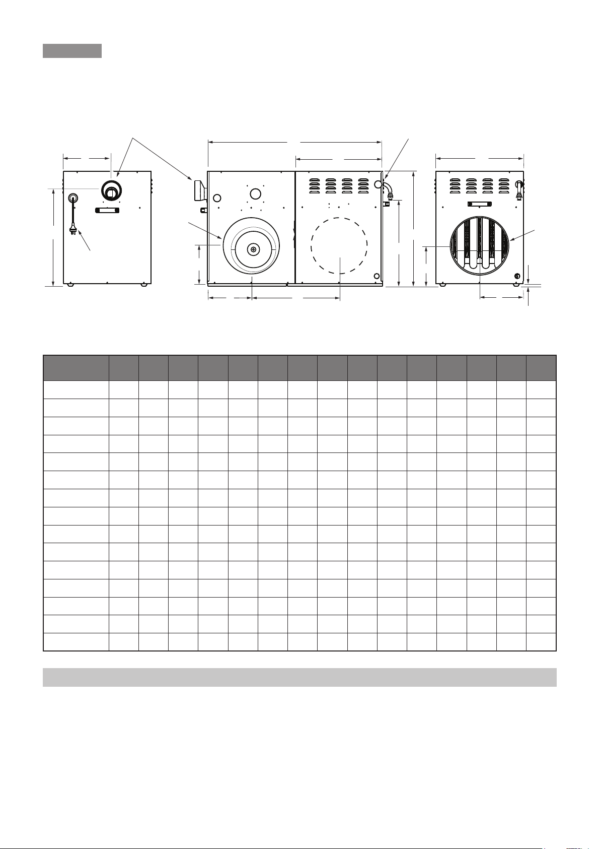
3.1 HEATER DIMENSIONS – SP4, SP5 AND SP6
Diagram 1. SP4, SP5 and SP6 Universal Heater Dimensions (SP6U illustrated)
M
L
POWER LEAD
FLUE OUTLET
ØRa
H
G
K
J
N
GAS INLET
B
ØSa
E
F
D
C
Table 1. SP4, SP5 and SP6 Universal Heater Dimensions (mm)
UNIVERSAL
MODEL
SP415UN 14 397 197 235 625 467 448 845 197 235 95 495 447 300 300
SP421UN 14 397 197 235 625 467 448 845 197 235 95 495 447 300 300
A B C D E F G H J K L M N øSa øRa
A
SP430UN 14 549 197 235 644 487 497 923 237 235 250 515 487 350 350
SP435UN 14 549 197 235 644 487 497 923 237 235 250 515 487 400 400
SP521UN-XA 14 428 214 222 658 478 419 991 209 222 110 517 574 350 350
SP521UN 14 428 214 222 658 478 419 991 209 222 110 517 574 300 300
SP530UN-XA 14 550 275 222 707 526 419 1083 209 222 250 565 574 400 400
SP530UN 14 550 275 247 707 526 539 1083 270 247 250 565 539 350 350
SP535UN 14 550 275 247 707 526 539 1083 270 247 250 565 539 450 450
SP615UN 14 428 214 222 658 478 419 991 209 222 110 517 574 300 300
SP623UN-XA 14 428 214 222 658 478 419 991 209 222 110 517 574 350 350
SP623UN 14 428 214 222 658 478 419 991 209 222 110 517 574 300 300
SP630UN-XA 14 550 275 247 707 526 539 1083 270 247 250 565 539 400 400
SP630UN 14 550 275 247 707 526 539 1083 270 247 250 565 539 350 350
SP635UN 14 550 275 247 707 526 539 1083 270 247 250 565 539 450 450
Note: SP4, SP5 and SP6 Universal models are approved for internal or external applications.
Rinnai 11 Ducted Gas Heater IM
Page 12
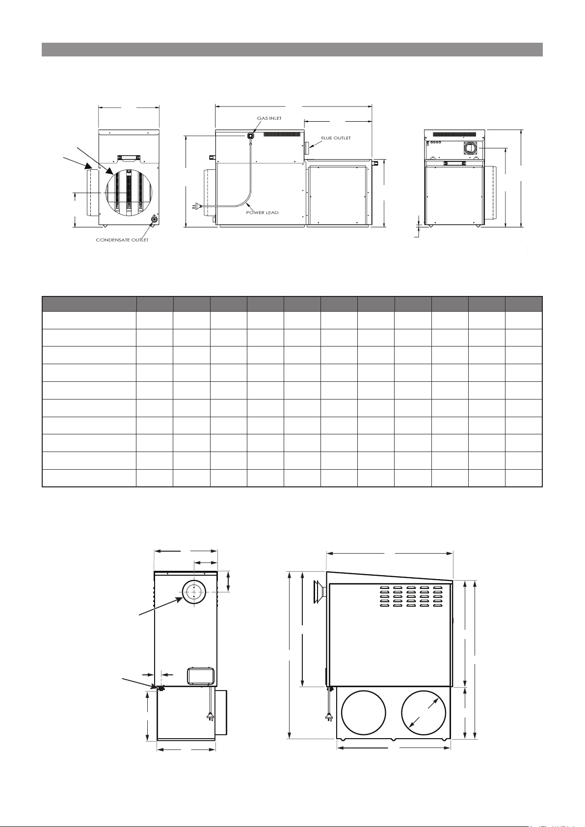
Diagram 2. SP5/6 Internal Heater Dimensions
N
H
C
SP6 & SP5 Internal
A
C
øSa
øRa
D
J
(SP6 MODELS ONLY)
B
E
H
F
G
Table 2. SP5/6 Internal Heater Dimensions (mm)
INTERNAL MODEL A B C D E F G H J øSa øRa
SP521IN 634 1021 395 594 440 440 15 513 224 300 300
SP521IN-XA 634 1021 395 594 440 440 15 513 224 350 350
SP530IN 684 1070 547 643 491 490 15 563 253 350 350
SP530IN-XA 684 1070 547 643 491 490 15 563 253 400 400
SP535IN 684 1070 547 643 491 490 15 563 253 450 450
SP615IN 634 1021 395 594 440 440 15 513 224 300 300
SP623IN 634 1021 395 594 440 440 15 513 224 350 350
SP623IN-XA 684 1070 547 643 491 490 15 563 253 350 350
SP630IN 684 1070 547 643 491 490 15 563 253 400 400
SP630IN-XA 684 1070 547 643 491 490 15 563 253 450 450
3.2 HEATER DIMENSIONS – BX5
Diagram 3. BX5 Heater Dimensions
TERMINAL
INLET
GAS
FLUE
F
G
A
J
E
B
K
L
D
Ø P
M
Rinnai 12 Ducted Gas Heater IM
Page 13
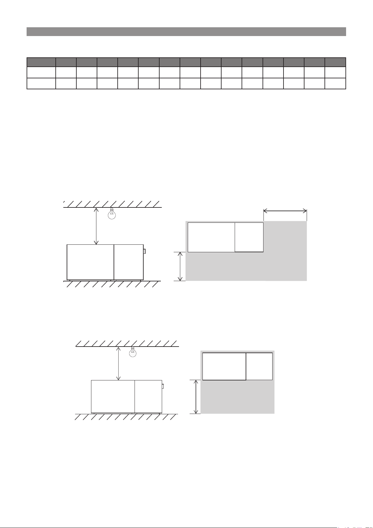
Table 3. BX5 Heater Dimensions (mm)
Side View Plan View
MODEL A B C D E F G H J K L M N P
BX520 775 852 420 341 41 156 135 391 1145 715 1085 370 771 300
BX526 866 1028 582 387 41 238 135 557 1280 805 1220 415 951 350
3.3 SERVICE CLEARANCES – INTERNAL
3.3.1 Service Clearance Notes
All SP6 models, SP5 models, SP415 and SP421 models can be installed in accordance with 'Method 1',
'Method 2', 'Method 3' and 'Method 4' below. The SP430 and SP435 can be installed in accordance with 'Method 1'
and 'Method 2' only.
3.3.2 Internal Clearances
Method 1: In Ceiling and Under Floor
Diagram 4. Method 1 Clearances
750mm
Minimum
250 mm
Minimum
Heat
Exchanger
Cabinet
Fan Cabinet
Heat
Exchanger
Cabinet
Fan
Cabinet
Side View Plan View
Method 2: In Ceiling and Under Floor
Diagram 5. Method 2 Clearances
800 mm
Minimum
Heat
Exchanger
Cabinet
Fan
Cabinet
750mm
Minimum
750mm
Minimum
Service Clearance
Heat
Exchanger
Cabinet
Service Clearance
Platform
Fan Cabinet
Platform
Rinnai 13 Ducted Gas Heater IM
Page 14

Method 3: Lay-down Option – In Ceiling
Diagram 6. Method 3 Clearances
700 mm
Service
Clearance
(Full length of heater)
300 mm (refer to AS5601)
750 mm
Method 4: Lay-down Option – Under Floor
Diagram 7. Method Clearances
700 mm
Service
Clearance
(Full length of heater)
750 mm
200 mm (
Side View
refer to AS5601)
Concrete Base 50mm
Side View
Fire resistant board
(refer to AS5601)
Lowest part of floor structure
Ground
Note: Method 3 and Method 4 are not options for SP430 and SP435 models. These models may be installed to Method 1 or Method
2 only.
3.4 SERVICE CLEARANCES – EXTERNAL
3.4.1 Installation of Flashing
The flashing must be fitted to ensure the ductwork is adequately weather protected.
Note: To allow the heater to be moved out from the wall such as for servicing, it is important to provide additional length in the ducting
connected to the pops.
3.4.2 SP4, SP5 and SP6 External Clearances
Front: A minimum of 500mm must be provided at the side facing away from the house.
End: A minimum of 300mm must be provided at each end of the heater.
Top: A minimum of 1000mm must be provided above the heater roof. This clearance must be maintained for the
entire surface area of the heater roof.
Rinnai 14 Ducted Gas Heater IM
Page 15

Diagram 8. External Clearances
Plan View
1000 mm min
Service
Clearance
(Top)
Side View
500 mm min
(Front)
Service Clearance
Flashing
Service
Clearance
(Front)
300 mm
min
300 mm
min
(End)(End)
500 mm
min
3.4.3 BX5 Service Clearances
Front: A minimum of 500mm must be provided at the side facing away from the house.
End: A minimum of 300mm must be provided at each end of the heater.
Top: A minimum of 1000mm must be provided above the heater roof. This clearance must be maintained for the
entire surface area of the heater roof.
Diagram 9. BX5 Clearances
Plan View
1000 mm min
Service
Clearance
(Top)
Side View
500 mm min
(Front)
300 mm
min
(End) (End)
Service Clearance
300 mm
min
Service
Clearance
(Front)
500 mm
min
Flashing
Rinnai 15 Ducted Gas Heater IM
Page 16

4. HEATER CONFIGURATION
4.1 HEATER DUCT POP INSTALLATION
On all SP series heaters, the duct connection pops need to be fastened to the heater cabinet as follows:
• Insert pops into the hole in the pop plate, ensuring the pop flange is placed over the prescribed wall of the
cabinet, refer to Table 4.
• Spread pop flange to fit tightly into the hole in the cabinet (the notch side overlapping the other).
• Secure pops with the rivets supplied.
Table 4. Pop Installation
Matrix
Universal Model Cabinet
Internal Model Cabinet
No. of Walls Install Pop No. of Walls Install Pop
SP4 2 Inner Wall 2 Inner Wall
SP5 1 No Option 2 Inner Wall
SP6 1 No Option 2 Inner Wall
SP5 1 No Option 2 Inner Wall
SP6 1 No Option 2 Inner Wall
Return Air Supply Air
4.2 DUCT CONNECTION CONFIGURATION OPTIONS
(Not applicable BX5 Models)
For SP Series heaters, the return air and supply air duct connections can be reconfigured. That is, the heater panels
can be repositioned to move the duct outlet/inlet to the back or to the side of the unit to suit the specific installation.
Change Duct Connection Locations
Simplistically, the heater unit is made up of two cabinets: a heater cabinet (air heating components) and a fan
cabinet, (supply air fan). Diagram 10 identifies three pop positions on the heater cabinet (H1, H2 and H3) and three
pop positions on the fan cabinet (F1, F2 and F3).
Diagram 10. Duct Connection Options
Return Pop Position
from Factory
H1
HEATER CABINET FAN CABINET
F1
SUPPLY AIR
SIDE
Supply Pop
H3 F3
Position
from
Factory
H2
RETURN AIR
SIDE
F2
SP430U and SP435U: The pops can be configured to support any combination of the following options:
• Return air pop: Can be positioned at F1 or F2 (Diagram 10).
• Supply air pop: Can be positioned at H1, H2 or H3.
SP415U, SP421U, SP5U and SP6U: The pops can be configured to support any combination of the following
options:
• Return air pop: Can be positioned at F1, F2 or F3 (Diagram 10).
• Supply air pop: Can be positioned at H1, H2 or H3.
SP5 and SP6 Internal: The return air pop can be configured to support any combination of the following options:
• Return air pop: Can be positioned at F1 or F2 or F3 (Diagram 10).
• Supply air pop: Can be positioned at H3 only.
Rinnai 16 Ducted Gas Heater IM
Page 17

Return Air Orientation
4.2.1 SP430U and SP435U Fan Cabinet: Swap F1 – F2
a. Remove the lid.
b. Remove F1 and F2 panels (Diagram 10).
c. Remove the internal blanking panel (four screws behind insulation).
d. Install the blanking panel in the required position.
e. Install F1 and F2 panels in the required positions.
f. Install the lid.
4.2.2 SP415U, SP421U Fan Cabinet: Swap F1/F2 – F3
(Not available for SP430U and SP435U)
a. Remove the lid (Diagram 10).
b. Remove the F3 handle and flue terminal, and then remove the panel.
c. Remove the flue hole blanking plate from F1 or F2 as required, then remove the panel.
d. Remove the internal blanking panel (four screws behind insulation).
e. Install the blanking panel in the required position.
f. Install the panels in the required positions.
g. Install the flue terminal and flue hole blanking plate.
h. Install the lid.
4.2.3 SP5U and SP6U Fan Cabinet: Swap F1 – F2
a. Remove the lid (Diagram 10).
b. Remove F3 handle and panel.
c. Remove F1 and F2 panels.
d. Install F1 and F2 panels in the required positions.
e. Install F3 panel and handle.
f. Install the lid.
4.2.4 SP5U and SP6U Fan Cabinet: Swap F1/F2 – F3
a. Remove the lid (Diagram 10).
b. Remove the F3 handle, and then remove the panel.
c. Press the pre-cut opening for the flue from F1/F2 panel as required.
d. Install the panels in the required positions. (Install the end panel and handle last).
e. Ensure the flue is correctly installed.
f. Install the lid.
4.2.5 SP5 and SP6 Internal Fan Cabinet: Swap F1 – F2/F3
a. Remove the screws securing the side pop plate F1 and blanking plate F2/F3 and remove the plates.
b. Install the panels in the required positions
IMPORTANT: RETURN AIR CONNECTION AT THE END OF THE UNIT - REAR ENTRY (F3)
Connecting the return air duct to the end of the unit reduces the rated airflow by up to 30%. The total number of outlets normally permitted
for a heating system shall be reduced by 2 (predominantly when a unit is laid down). Refer to the outlet register chart on "Table 9. Outlet
Register Chart" on page 34
For ADD-ON cooling applications, MAKE SURE that the minimum recommended airflow is maintained. Refer to the
ADD-ON installation manual for more information.
Rinnai 17 Ducted Gas Heater IM
Page 18
IMPORTANT: RETURN AIR CONNECTION AT THE END OF THE UNIT (F3)
Connecting the return air duct to the end of the unit reduces the rated airflow by up to 30%.
For ADD-ON cooling applications, MAKE SURE that the minimum recommended airflow is maintained. Refer to the
ADD-ON installation manual for more information.
Supply Air Orientation
4.2.6 SP4 Heater Cabinet: Swap H1/H2 – H3
a. Remove the lid (Diagram 10).
b. Remove the H3 handle, and then remove the panel.
c. Remove H1 or H2 panel as required.
d. Remove the internal blanking panel (four screws behind insulation).
e. Install the blanking panel in the required position.
f. Install the external panels in the required positions.
g. Install the lid.
4.2.7 SP5 and SP6 Heater Cabinet: Swap Any Combination of H1, H2 or H3
a. Remove the lid (Diagram 10).
b. Remove H3 panel.
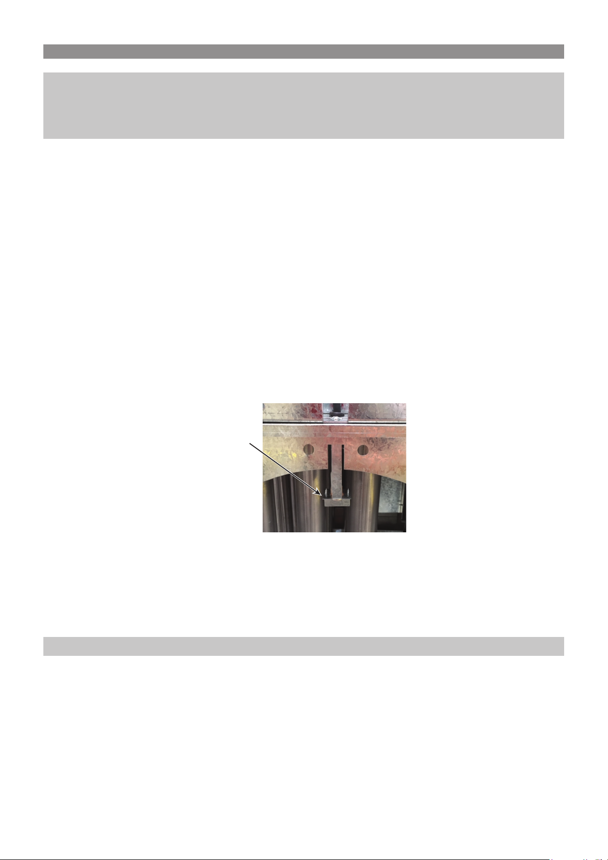
Diagram 11. Overheat Switch
Overheat
Switch
c. Remove H1 or H2 panels.
d. Remove the H1 or H2 internal panels (four screws each, behind insulation)
e. Install the internal panels in the required positions.
f. Install the external panels. (Install the end panel and handle last).
g. Install the lid.
Note: Ensure the overheat switch loom is not tangled, tight or pinched.
Supply Air Switch Position – SP623U/630U/521U
4.2.8 Supply Air Switch Position
All SP units leave the factory configured for an internal installation with the supply air pop at the heaters end, refer
to diagram 12A. When models detailed in Table 5 are reconfigured to an external installation the supply air overheat
switch assembly must remain secured to the internal supply air pop panel. The supply air overheat loom for external
installations must be rerouted and path is dependent on the nominated supply air side of heater, refer to diagrams
12B and 12C to identify the requirements. All other models within this manual not detailed in Table 5 have a fixed
supply air overheat switch position for internal and external configurations.
Rinnai 18 Ducted Gas Heater IM
Page 19
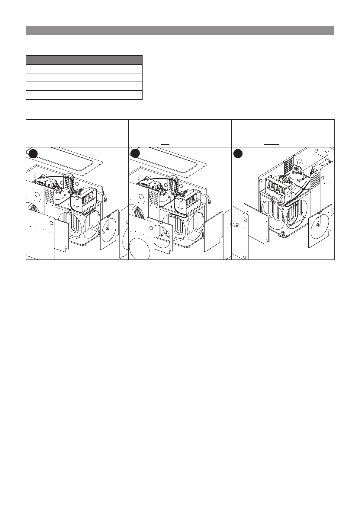
Table 5. Models with variable supply air O/H switch location
SP6 Models SP5 Models
SP623U SP521U
SP623U XA SP521U XA
SP630U
SP630U XA
Diagram 12. Overheat switch position and loom route
Diagram 12A:
Internal configuration from factory
A
Diagram 12B:
External configuration.
Supply air fan side.
B
Diagram 12C:
External configuration.
Supply air motor side.
C
4.3 SP SERIES GAS FEED TUBE INSTALLATION
SP4, SP5 and SP6 model heaters are supplied with a gas feed to be in the controls area beneath the lid. The gas
feed shall be installed on to the heater gas valve and tested for leaks.
For Universal heaters install the gas feed tube as follows:
a. Change the pop (duct connection) locations as required. This ensures the pre-cut blanking plate is removed from
the correct cabinet panel.
b. Remove the pre-cut blanking plate covering the hole in the upper corner of the end panel near the gas valve
assembly.
c. Position the gas feed tube from the gas valve out through the hole.
d. Install the compression fitting to the valve assembly to connect the feed tube. Do not over-tighten the compression
fitting.
Rinnai 19 Ducted Gas Heater IM
Page 20
5. CONDENSATE REMOVAL
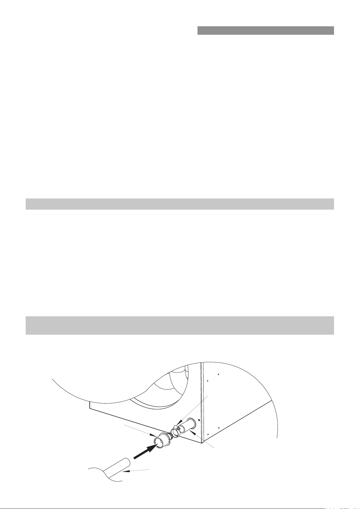
All SP6 models have a condensate drain outlet. A fitting and clamp are provided loosely beneath the heater lid for
connection to the drain (refer to Diagram 13).
• The outlet is located in the bottom corner below the gas supply connection point.
• The condensate is mildly acidic, and shall be run via a PVC pressure pipe (to AS 1477), with an outside
diameter of approximately 27mm, away from the heater to a suitable area (i.e. to above a drain, sewer or pit)
• Use PVC cement on all joints to prevent any condensate leakage.
• Do not connect the condensate drain directly to the sewer or below ground level of a storm water drain. A
blockage in the drain system would cause the heater condensate tank to flood with water and shut down. Check
for any additional local drainage codes which may apply.
• Under no circumstances should it be allowed to run onto electrical connections, earth stakes, copper pipes or
concrete paths. It should also not discharge onto metallic roofs or guttering, however the condensate drain may
terminate into the vertical section of a downpipe above ground level.
• Tube length should be minimised and a continuous fall of 20mm per metre created. Maximum equivalent tube
length of 12m is recommended (or increase diameter size).
• Under no circumstances should any part of the tube sag or run uphill.
• Special consideration is required for installation in areas experiencing sub-zero temperature as condensate
could freeze in the drain. In these cases, larger diameter drainage piping is required.
• Approximately 2 to 3 litres per hour of condensate may be produced under continuous running conditions,
depending on the size of the heater.
Note: Ensure adherence to these instructions: Incorrect drainage can cause serious damage to the heater and/or its surroundings.
5.1 CONDENSATE DRAIN
Fitment of the 'BARBED CONNECTOR" and 'DN 20 PRESSURE PIPE' is identical for SP6U internal and external
installations.
5.1.1 Install a Condensate Drain to an SP6 Universal and Internal Units
a. Retrieve the barbed connector and hose clamp supplied loosely in the controls area beneath the lid.
b. Slide the hose clamp over the flexible hose.
c. Fit the barbed connector to the flexible condensate hose (refer to Diagram 13).
d. Fasten the hose to secure the barbed connector to the flexible hose.
e. Fit the DN20 pressure pipe drain to the barbed connector.
Note: Always use the correct PVC cement to bond the field supplied PVC pressure pipe to the barbed connector, following the
instructions as detailed for the PVC cement for proper bonding and curing.
Diagram 13. Condensate Drain Installation
HOSE CLAMP
(Supplied)
BARBED CONNECTOR
(Supplied)
FLEXIBLE CONDENSATE HOSE
DN20 PRESSURE PIPE
(Field Supplied)
Rinnai 20 Ducted Gas Heater IM
Page 21
6. HEATER POSITIONING
Install the heater in a position that allows adequate and safe access for service as per guidelines in this manual
and applicable standards. The cost of any equipment and additional labour involved in accessing such heater
installations will not be accepted by the manufacturer.
Note: Service clearance measurements must be complied with, to avoid impeding the serviceability of the heater.
6.1 WALL CUT-OUT AREA
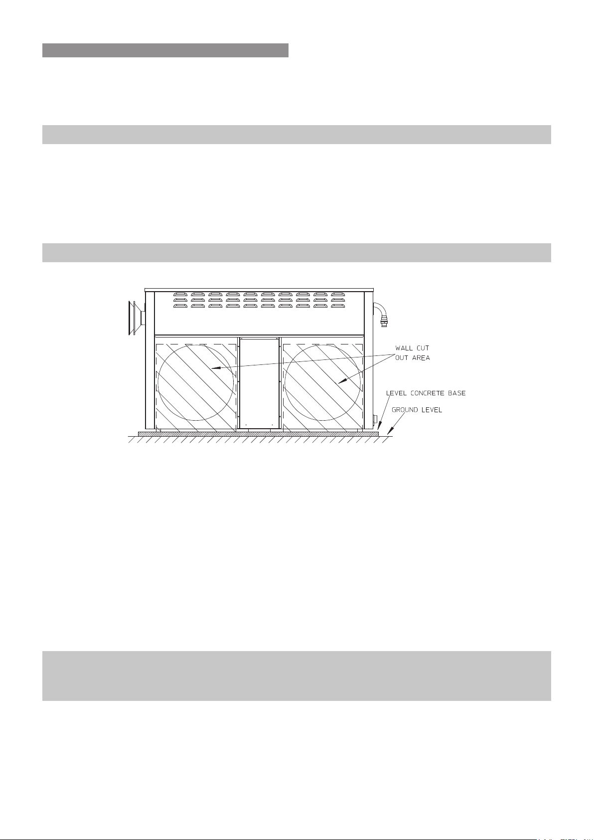
6.1.1 When installing the heater at ground level, create two holes to suit the pops, ensuring there is no
impediment to the structural integrity of the dwelling. Create two holes all the way to ground level (refer to
Diagram 14), or one hole to cover the distance of both pops.
Note: Refer to Table 1 to obtain the dimensions for the model of heater being installed.
Diagram 14. Wall Cut-out Area
6.2 SPLITTING HEATER FOR ASSISTED LIFTING AND POSITIONING
(Not applicable BX5 Models)
The SP series heaters can be split for ease of installation.
6.2.1 SP4 Universal Heater
a. Remove the lid (four screws).
b. Disconnect the gas valve, overheat/pressure switch loom, igniter and flame sensor from the PCB.
c. Disconnect the flue pipe.
d. Remove the screws fastening the fan cabinet tabs to the heat exchanger cabinet. These are located at the top
of the heat exchanger cabinet on the heater split line.
e. Tilt the fan cabinet back and slide away from the heater cabinet.
Note:
• Protect the exposed looms and tabs from damage while the heater is split.
• Ensure when reassembling the heater that all items are correctly installed and connected.
f. To assemble the heater, follow the procedure in the reverse order ensuring that:
• the two locating brackets at the base of the cabinets are fully engaged, and
• all switches, the gas valve and the flue pipe are correctly installed.
Rinnai 21 Ducted Gas Heater IM
Page 22

6.2.2 SP5 Universal Heater
a. Remove the lid (four screws).
b. Disconnect from heater PCB all looms connected to components on the heat exchanger cabinet side.
c. Disconnect the pressure switch hose.
d. Remove the screws fastening the fan cabinet tabs to the heat exchanger cabinet. These are located at the top
of the heat exchanger cabinet on the heater split line.
e. Tilt the fan cabinet back and slide away from the heater cabinet while at the same time removing the flue pipe
from the combustion fan.
Note:
• Prior to splitting the SP5 and SP6 you may remove the flue pipe by removing the flue terminal (SP5) and sliding the pipe from the
combustion fan.
• Protect the exposed looms and tabs from damage while the heater is split.
• Ensure when reassembling the heater that all items are correctly installed and connected.
f. To assemble the heater, follow the procedure in the reverse order ensuring that:
• the two locating brackets at the base of the cabinets are fully engaged, and
• the flue pipe is pushed fully onto the combustion fan assembly.
6.2.3 SP5 and SP6 Internal Heater
a. Remove the heater’s roof after removing the 4 roof screws.
b. Disconnect the speed sensor loom from the control board and remove it from the heat exchanger cabinet.
c. Remove the main fan motor and speed sensor loom access plate located on top of the fan cabinet
compartment by removing the single screw.
d. Remove the 2 screws fastening the fan cabinet tabs to the heat exchanger cabinet. These are located at the
top of the fan cabinet on the heater’s split line.
e. Pivot the fan cabinet upwards high enough to dislodge the lower locking tabs fixed to the fan cabinet near the
base.
f. The heater is now split in two.
g. Protect the exposed looms and tabs from damage while the heater is split in two parts.
h. Once ready, reassemble in reverse order.
Note: Ensure when reassembling the heater that everything is put back and connected correctly.
6.2.4 SP6 Universal Heater
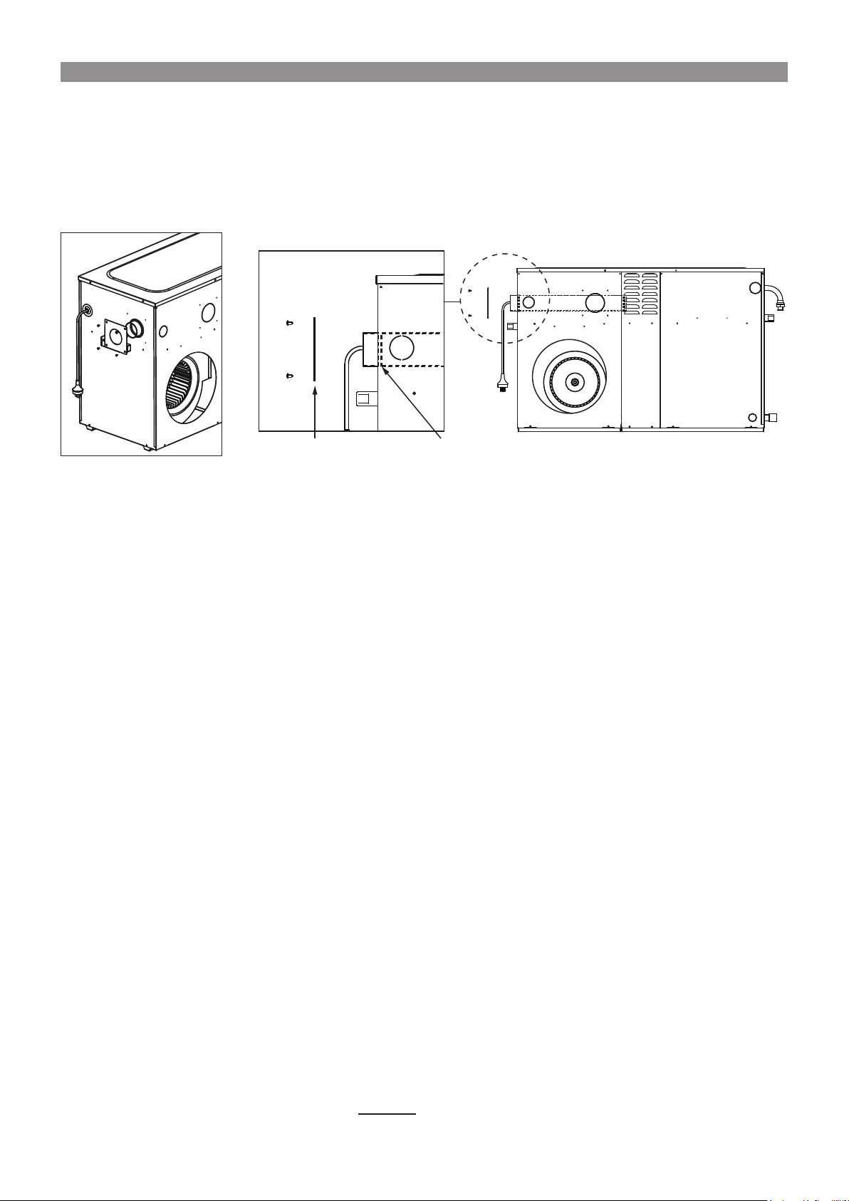
The flue pipe is captive within the cabinet, retained by an ‘O-Ring Groove’ on the flue pipe and a ‘Clearance Plate’.
To split the cabinet the flue pipe must be removed from the cabinet "Diagram 15. SP6U flue removal" on page 23.
To remove the flue pipe from the cabinet do the following:
a. Remove the lid (four screws).
b. Remove the four screws securing the ‘Clearance Plate’ to the cabinet, refer Diagram 15.
c. Remove the ‘Clearance Plate’ from the flue pipe.
d. Remove the flue from the combustion fan and the heater cabinet.
e. Disconnect from heater PCB all looms connected to components on the heat exchanger cabinet side.
f. Disconnect the pressure switch hose.
g. Remove the screws fastening the fan cabinet tabs to the heat exchanger cabinet. These are located at the top
of the heat exchanger cabinet on the heater split line.
h. Tilt the fan cabinet back and slide away from the heater cabinet while at the same time removing the flue pipe
from the combustion fan.
Rinnai 22 Ducted Gas Heater IM
Page 23
i. To assemble the heater, follow the procedure in the reverse order ensuring that:
• the two locating brackets at the base of the cabinets are fully engaged, and
• the flue pipe is pushed fully onto the combustion fan assembly.
Diagram 15. SP6U ue removal
Clearance Plate
O-Ring Groove
6.3 INTERNAL INSTALLATIONS
SP series heaters that are installed in the roof or beneath the floor shall comply with the following guidelines and
AS/NZS 5601.
6.3.1 Installation in the Roof Space
• The area under the heater must be capable of supporting the additional load, without causing deformation of
any part of the building structure.
• The appliance must be accessible by means of fixed access, a normal ladder or steps.
• A passage of 600mm wide must be provided between the roof access opening and the heater.
• This passage must have a suitable walkway of at least 19mm thick particle board or equivalent.
• A permanent level platform must be provided beneath the heater and this platform area must extend 750mm out
from the controls access panel side and fan motor access panel side/s for the entire length of the heater.
• The air gap created between the base of the heater and the platform by the heater’s legs must be maintained.
• Permanent artificial lighting must be provided at the heater, with the switch located at the roof access opening.
• If a lay-down kit is used the supporting platform must be covered with a fire resistant material.
6.3.2 Installation Beneath the Floor
• There must be a minimum clearance of 200mm between any part of the appliance and the lowest part of the
floor structure. In addition to this, refer to Service Clearances 3.3 (internal) or (external).
• The heater must be located within 2m of the access opening, or with a minimum clearance of 1.2m between the
lowest part of the floor structure and ground level, maintained from the access opening to the heater.
• All under floor installations must be on a level concrete base (50mm thick), and provision made to drain any
condensate, seepage or ground water away from the heater.
• Permanent artificial lighting must be provided at the heater with the switch located at the access opening.
• Lateral (horizontal) flues may be installed in accordance with AS/NZS 5601, ensuring that the lateral flue section
has a minimum rise of a 20mm per metre of lateral run.
• The flue must be terminated outside the building in accordance with AS/NZS 5601. For SP series heaters,
termination can be performed using a remote terminal. Refer to para 7.1.4.
6.3.3 Ventilation Calculations
For installation of universal heaters in a room, enclosure, residential garage, or plant room with natural ventilation
conditions, ensure adequate ventilation is available by utilising the following formulae:
Properties Approved for Construction prior to 31st March 2014
a. Determine if the rating per cubic metre of the space is greater than 3MJ/hr.
Rinnai 23 Ducted Gas Heater IM
Page 24
Example:
Unit rating (Ur) = 120MJ/hr
Room volume (Rv) = 1m x 1m x 2.4m = 2.4m
Ur/Rv = 120/2.4 = 50 MJ/hr per m
3
3
As the result is greater than 3 MJ/hr per cubic metre of the space, additional ventilation is required.
b. Two permanent openings are required, each equivalent in area to the determined value A. The lower vent shall
be located close to the floor or at burner level. The upper vent shall be located at or above the top of the unit.
The two openings may be combined as long as the above conditions are met.
Determine free ventilation area using A = T x F, where:
A = minimum free ventilation area, mm
2
T = total gas consumption of all gas appliances, MJ/hr. e.g. SP521UN = 90MJ/hr
F = factor (detailed in the table below)
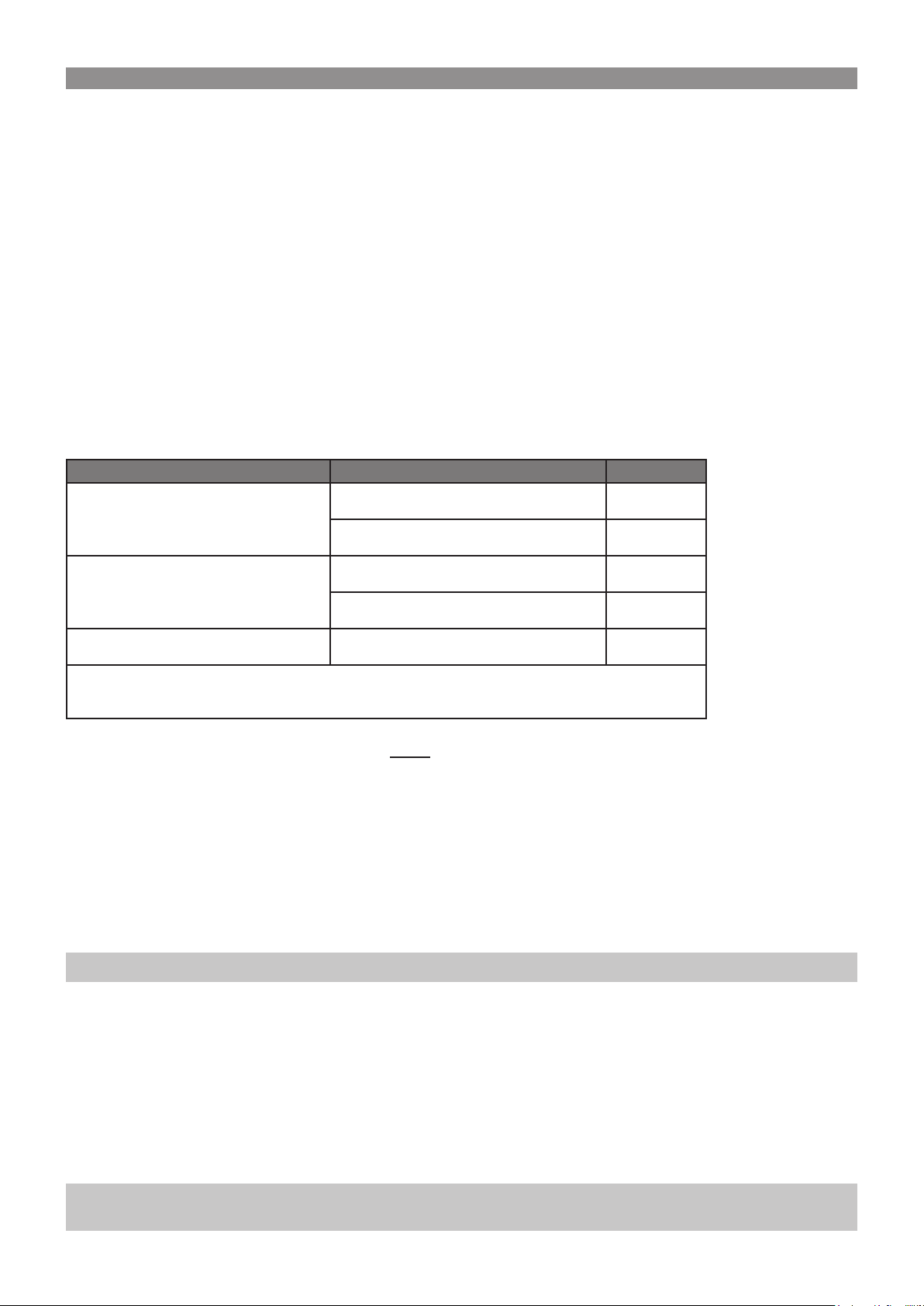
Table 6. Ventilation F Factors
Gas appliance location Source of Ventilation Factor F
Directly to outside* 300
Gas appliance in a room or enclosure
Via an adjacent room 600
Directly to outside* 150
Gas appliance in a plant room
Via an adjacent room 300
Gas appliance in a residential garage Directly to outside* 300
* Directly to outside means through an external wall to outside, into a cavity vented to outside,
into an underfloor space vented to outside, or into a roof space vented to outside.
Properties Approved for Construction after 31st March 2014
c. Determine if the rating per cubic metre of the space is greater than 0.4 MJ/hr.
Example:
Unit rating (Ur) = 120MJ/hr
Room volume (Rv) = 1m x 1m x 2.4m = 2.4m
Ur/Rv = 120/2.4 = 50 MJ/hr per m
3
3
As the result is greater than 0.4 MJ/hr per cubic metre of the space, additional ventilation is required.
Refer to AS/NZS 5601 for natural ventilation requirements.
Note: For New Zealand ventilation requirements and all other applications, e.g. Mechanical Ventilation, refer AS/NZS 5601.
6.4 EXTERNAL INSTALLATIONS
SP4, SP5, SP6 Universal and BX5 models can be installed outside of the house. For an installation under a house
floor, an SP4, SP5 or SP6 Universal model should be chosen.
All heaters that are installed externally on the ground should be installed on a level concrete base or pad, and there
must be provision made to drain away any surface water from the heater and condensate for SP6 models. If the
heater is to be installed in an elevated position or on a roof, the installation shall comply with AS/NZS 5601. It must
be secured to prevent movement and it must have adequate provision for service access.
Note: To allow the heater to be moved out from the wall such as for servicing, it is important to provide additional length in the ducting
connected to the pops.
Rinnai 24 Ducted Gas Heater IM
Page 25

6.4.1 SP4 – Installation of Flashing
For installation details refer to the instructions supplied with associated flashing kit.
6.4.2 SP5 and SP6 – Installation of Flashing
For installation details refer to the instructions supplied with associated flashing kit.
Note: To allow the heater to be moved out from the wall such as for servicing, it is important to provide additional length in the
ducting connected to the pops.
Rinnai 25 Ducted Gas Heater IM
Page 26
7. FLUE INSTRUCTIONS AND CLEARANCES
7.1 INTERNAL – SP SERIES
7.1.1 General
• All flues shall be installed in accordance with AS/NZS 5601.
• Horizontal flues shall have a minimum rise of 20mm per 1m run.
• Horizontal flues terminating on a wall shall be at least 300mm above ground level.
• An external flue terminal clearance to an opening in a building shall be no less than 1000mm in the vertical
direction and 300mm in the horizontal direction.
• Systems with both vertical and horizontal flue runs should be treated as all horizontal.
• One 45º bend is equivalent to one half 90º bend (i.e. two 45º bends = one 90º bend).
• Provide adequate support to flue sections (e.g. saddles / strapping).
7.1.2 SP4 and SP5 Models – 100mm Non-corrosive Metal Flue.
• Requires a 100mm round single or twin wall non-corrosive metal flue, suitably terminated.
• All flues shall have a bolted flue sleeve connection to allow for repairs and/or removal of the appliance.
• Twin Wall flue – maximum flue length of 6m.
• Single Wall flue – maximum flue length of 2m.
• Up to four 90º elbows are permitted with the same length requirements specified above.
7.1.3 SP6 Universal Models – 100mm Drainage Waste Vent (DWV) Flue
Level Invert Taper (LIT)
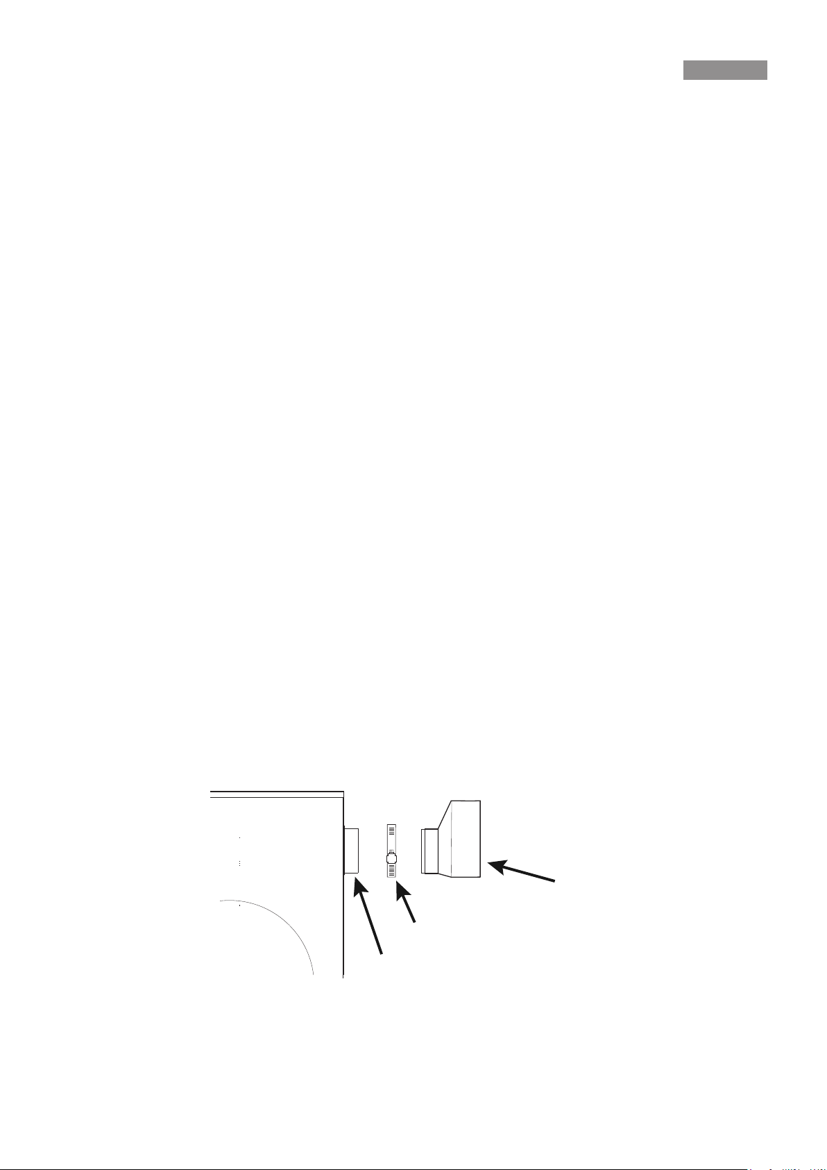
All SP6 internal model heaters are supplied with an LIT fitting in the controls area beneath the lid. The LIT must be
installed to the heater flue outlet. The flue outlet connection can be found behind an installer instruction label.
The (field supplied) flue is connected to the unit via a 100mm drain waste vent pipe (DWV to AS/NZS 1260) and
must be secured to the LIT with the supplied 100mm pipe clamp.
Install the LIT as follows:
a. Place the supplied 65mm pipe clamp loosely over the LIT.
b. Gently install the LIT onto the flue pipe ensuring that:
• the rubber is not pinched or folded;
• the LIT is in the correct orientation (Diagram 17); and
• the LIT is pushed onto the flue pipe until it is firmly against the cabinet.
c. Secure the LIT firmly in place with the 65mm pipe clamp.
Diagram 16. LIT
LIT
65mm Pipe Clamp
Flue Outlet
The DWV flue shall be installed in accordance with the following:
• All flue joints shall be adequately sealed to prevent condensate leakage.
• Ensure there is continual fall back to the flue outlet on the heater from flue termination point.
• Flue shall be removable from the heater to allow for repairs and/or removal of the appliance.
• Flat side of the LIT (not tapered side) must be positioned so it is always the lowest part of the fitting or the
closest point to ground.
Rinnai 26 Ducted Gas Heater IM
Page 27
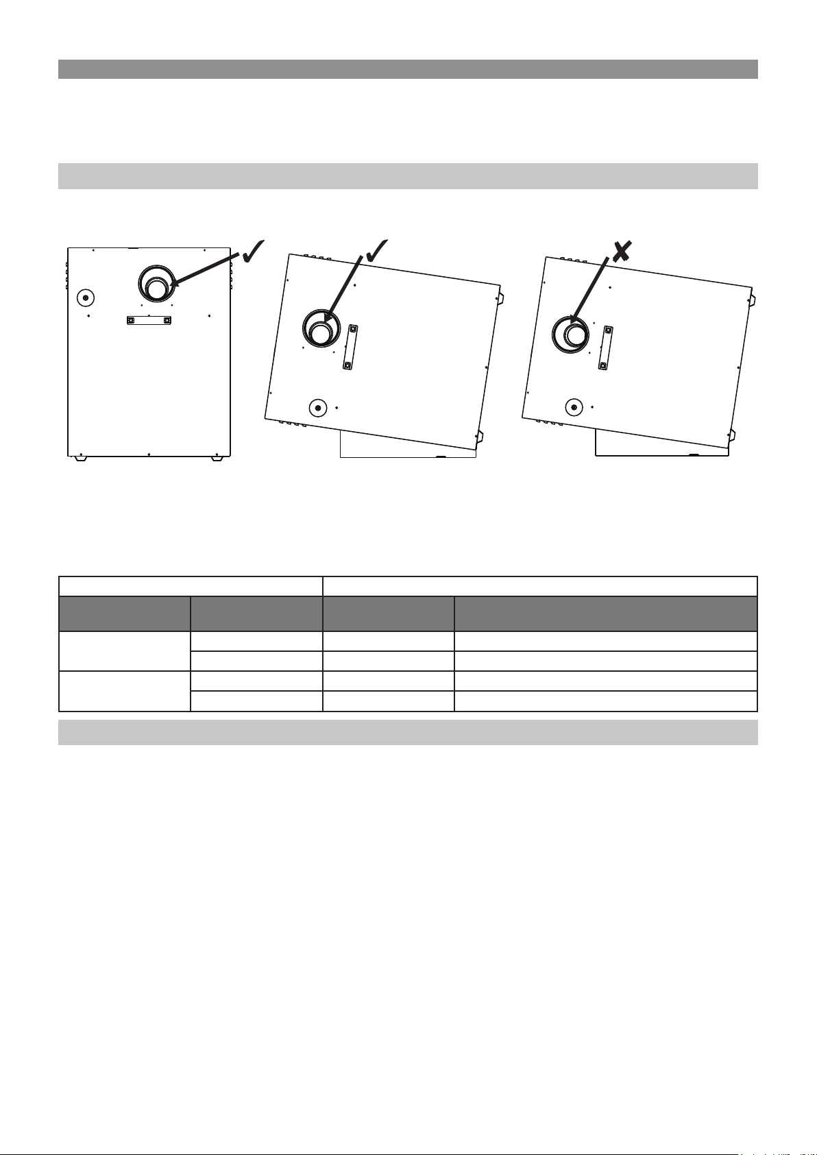
• Secure the LIT with the 100mm pipe clamp supplied.
• The DWV flue pipe shall be supported to ensure that no weight is transferred to the LIT.
Note: If a lay-down kit is used, the LIT must be rotated to ensure the flat side of LIT fitting is closest to ground (Diagram 17).
Diagram 17. LIT Orientation for Lay-down Installations
Standard Installation
Correct: LIT at Lowest Point Correct: LIT Rotated Incorrect: LIT Not Rotated
A maximum length of 25m x 100mm DWV flue pipe is allowed in all situations with no more than four 90º bends.
Refer to Table 7.
Lay-down Installation
Table 7. Maximum Flue Bends and Terminals
All SP6 Universal Models 100mm DWV Flue
Heater Orientation Flue Orientation
Standard
Lay-down
Vertical 25m 100mm DWV Plain Vent Cowl
Horizontal 25m Remote Flue Terminal
Vertical 25m 100mm DWV Plain Vent Cowl
Horizontal 25m Remote Flue Terminal
Note: One 45º bend is equivalent to one half 90º bend and all vertical flue orientations will have at least one 90º bend.
7.1.4 Remote Terminal (Part No. B018384) Internal Model Applications
In specific installations, for example under the floor, it is recommended that a remote terminal be used to terminate
the flue on the outside wall of the building. Please refer to the instructions supplied with a remote flue terminal.
Diagram 18 depicts a typical SP5 underfloor configuration.
90º Bends
(Up to 4)
Terminal Type
Rinnai 27 Ducted Gas Heater IM
Page 28
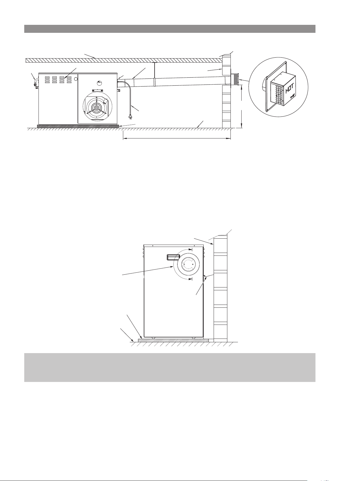
Diagram 18. Typical Remote Terminal Conguration - SP4 & SP5 Models
HOUSE FLOOR
BRIVIS REMOTE FLUE TERMINAL
Twin Wall Flue Maximum Length = 6 m
IMPORTANT
GAS
INLET
COMBUSTION AIR INLET
Fix in place
with screw
FLUE OUTLET
Minimum 20 mm rise per 1 metre run
POWER LEAD
LEVEL CONCRETE BASE
Single Skin Flue Maximum Length = 2 m
WALL
GROUND LEVEL
Minimum
300 mm
7.2 EXTERNAL – SP SERIES FLUE TERMINAL CLEARANCES
7.2.1 Installation of Flue Terminal
The flue outlet socket can be found behind an installer instruction label. The flue terminal must be ordered separately
when SP4, SP5 or SP6 is installed externally (Part No. B021385).
Remove the label and insert the flue terminal firmly into the flue outlet socket in the correct orientation to ensure the
flue gases are expelled away from the house (refer to Diagram 19).
Diagram 19. Flue Terminal Installation
ENSURE THE FLUE OPENING POINTS
AWAY FROM THE WALL
OPEN AREA OF
FLUE TERMINAL
LEVEL CONCRETE BASE
GROUND LEVEL
WALL
FLASHING
Note:
• The flue terminal must be ordered separately when SP4, SP5 or SP6 is installed externally (Part No. B021385).
• The flue terminal must always be installed before starting the heater.
Heaters that are installed outside the house should be positioned so that, when measured from the edges of the flue,
the following minimum clearances exist, which are in accordance with AS/NZS 5601:
75mm
• Out from the wall against which it is mounted.
• From a drain or soil pipe.
Rinnai 28 Ducted Gas Heater IM
Page 29

300mm
• From a flue terminal, cowl or combustion air intake.
• Below eaves, balconies or other projections.
• From the ground, above a balcony or other surface.
• To a return wall or external corner.
• Measured horizontally, from an opening window, door, non-mechanical air inlet or any other opening into the
building (except sub floor ventilation) or 1500mm in direction of discharge.
500mm
• From an electricity meter or fuse box (prohibited area extends to ground level).
1000mm
• Measured vertically, from an opening window, door, non-mechanical air inlet or any other opening into the
building (except sub floor ventilation).
• From a gas meter.
• From a mechanical air inlet, including a spa blower, measured both vertically and horizontally.
• A flue terminal of this type shall not be located under a roofed area, unless the roofed area is fully open on at
least two sides, and a free flow of air at the appliance is achieved.
7.3 EXTERNAL – BX5 FLUE TERMINAL CLEARANCES
The flue terminal is supplied and fitted to the heater. The flue terminal must be orientated correctly to ensure flue
gases are expelled away from the house (refer to Diagram 19).
Heaters should be positioned to ensure the following minimum clearances exist when measured from the edges of
the flue:
75mm – Wall
• From the wall against which the heater is mounted.
• From a drain pipe or soil pipe.
300mm – Flue, Cowl or Intake
• From a flue terminal, cowl or combustion air intake.
• Below eaves, balconies or other projections.
• From the ground, above a balcony or other surface.
• To a return wall or external corner.
• Measured horizontally, from an openable window, door, non-mechanical air inlet or any other opening into a
building with the exception sub-floor ventilation.
500mm – Meter or Fuse Box
• From an electricity meter or fuse box (prohibited area extends to ground level).
• Horizontally from any building structure
1000mm – Vent or Opening
• From an openable window, door, non-mechanical air inlet or any other opening into a building with the exception
of sub-floor ventilation; measured vertically.
• From a gas meter.
• From a mechanical air inlet, including a spa blower, measured both vertically and horizontally.
• A flue terminal of this type shall not be located under a roofed area, unless the roofed area is fully open on at
least two sides, and a free flow of air at the appliance is achieved.
Rinnai 29 Ducted Gas Heater IM
Page 30
8. THERMISTOR INSTALLATION
8.1 SP SERIES THERMISTOR INSTALLATION
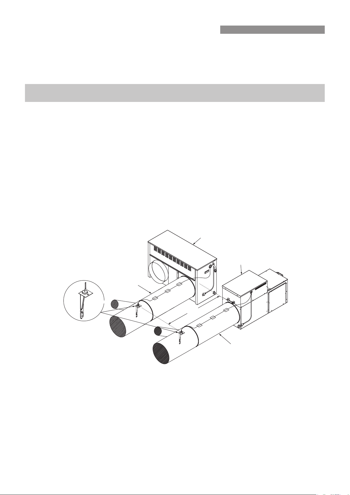
All SP series heaters are supplied with a remote thermistor assembly. The thermistor must be installed in the supply
air duct, between 1m to 3m away from the heater, but never beyond the first Branch Take Off (BTO) fitting.
Note: Where an Add-On air conditioning indoor evaporator coil is installed, the thermistor must be located in the discharge air pop
of the indoor coil.
These installation practices promote more accurate supply air temperature control and optimise heater performance.
• Ensure that there is at least 1 metre of appropriately sized ducting installed between the heater and the first
BTO fitting (or evaporator coil).
• Drill a 20mm diameter hole through the top of the inlet end of the first BTO fitting (refer to Diagram 20) or
through the top of the evaporator coil discharge pop.
• Carefully insert the thermistor assembly (probe end first) into this hole and secure using the self drilling screw
provided. Seal any remaining openings with duct tape.
• Ensure that the thermistor lead is secured to timbers or duct outer casing to prevent damage.
If the first BTO fitting is installed more than 3m away from the heater, an additional duct joiner (installer supplied) will
be required so that the thermistor assembly can be fitted correctly. Install the joiner between 1m and 3m away from
the heater, ensuring the thermistor can reach this joint. After making this modification, follow the steps per normal
practice.
Diagram 20. Duct Joiner Location
SUPPLY AIR DUCT
THERMISTOR
8.2 BX5 THERMISTOR INSTALLATION
UNIVERSAL MODEL
INTERNAL MODEL
1.0m to 3.0m
SUPPLY AIR DUCT
The thermistor is located on a bracket within the heat exchanger tubes and must be positioned correctly prior to the
installing unit onto a base box. Install a thermistor as follows:
a. Remove all packaging from the heater and basebox where applicable.
b. Remove the thermistor bracket secured to the heat exchanger
c. Position the thermistor bracket on the discharge pop lip and secure the arm with supplied mounting screw
(located in plastic bag containing the manuals). See "Diagram 21. Thermistor Mounting Location" on page 31
d. Position heater onto basebox and coil up excess loom into the corner of the basebox. Ensure thermistor loom is
not pinched between heater and basebox.
Rinnai 30 Ducted Gas Heater IM
Page 31
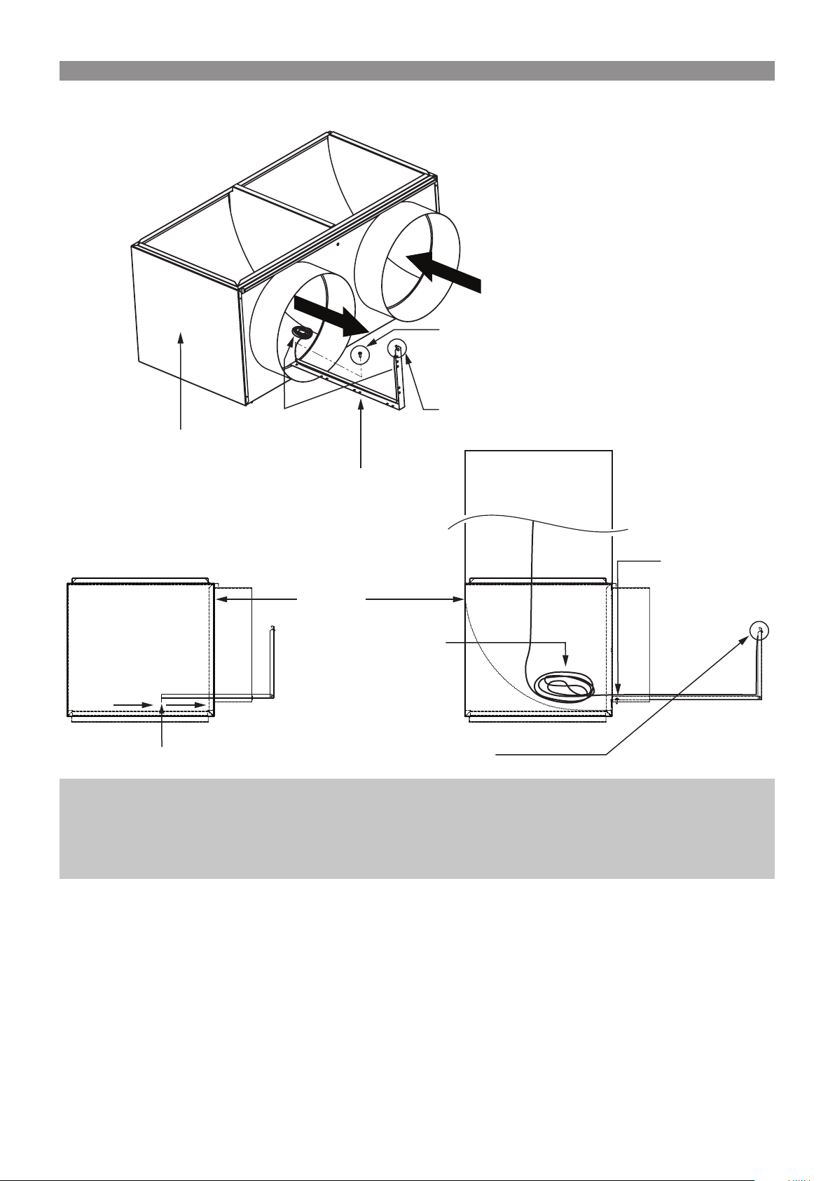
Diagram 21. Thermistor Mounting Location
AIRFLOW
AIRFLOW
Mounting screw
(supplied)
Loom
Thermistor sensor
Base box
Thermistor bracket
Heater
Base box
Push up to
the inner face
of basebox
Coil up
excess loom
Push
Locking tab
Thermistor sensor
Note: The thermistor bracket is affixed with supplied mounting screw at the discharge pop.
First hole with
mounting screw
supplied
• The loom can be installed either left or right handed, to be confirmed by installer.
• Remove bracket from heat exchanger and install as shown above.
• Be careful not to pinch the loom
Rinnai 31 Ducted Gas Heater IM
Page 32
9. DUCTING AND OUTLETS
9.1 DUCT DESIGN AND SIZING
Good duct design and sizing are essential to every Central Heating system. Use the Product Sizing Guide and
technical data within this manual for the best results and follow these guidelines:
• Ductwork should be well insulated and airtight and have a minimum insulation rating of R1.0 (R1.5 in some
areas). Ensure that ducting complies with the Building Code of Australia.
• The ducting should be well fastened to pops, BTOs, outlet boots and neck adapters adequately with duct tape,
in accordance with AS 4254, HB 276 and AS5141.
• It should also be properly sized, and curves and bends should be smooth enough to ensure that the air flows
through efficiently, quietly and with minimal resistance.
• The registers and diffusers should be large enough and of good design. They should minimise noise, while
providing the correct distribution pattern.
• The positive return air system should be fitted with a grille large enough to accept the full air capacity of the
system at low noise levels.
• If the system uses high level outlets (e.g. ceiling diffusers), then the return air inlet should be at a low level.
Ceiling systems with a high level return air may result in reduced performance.
• For SP4, SP5 and SP6 heaters, access to the ductwork must be provided for general maintenance and service
to the supply air thermistor sensor.
Note: It is important that the ducting should be well insulated. It is mandatory under building codes to install insulated, fire rated duct.
9.2 RETURN AIR GRILLE
If a filter is fitted to the return air grille, make sure it is easily accessible for regular cleaning.
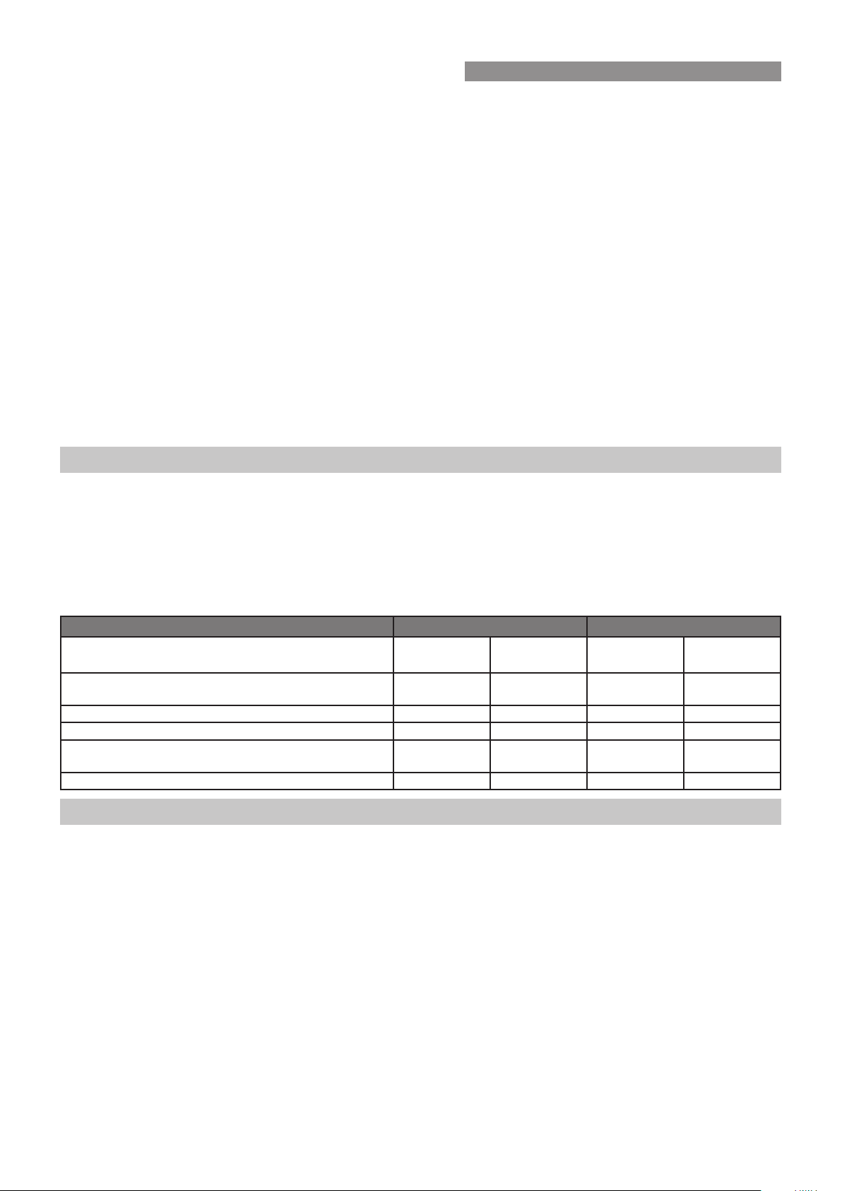
Table 8 gives the minimum recommended return air grille sizes for each model heater.
Table 8. Minimum Recommended Return Air Grille Selection
Without Filter With Filter
Model Grille Size
(m²)
SP415U, SP421U, SP521U, SP521IN, SP615U,
SP615IN, SP623U, SP623IN, BX520
SP521U-XA, SP521IN-XA, SP623U-XA, SP623IN-XA 0.28 (400x700) 0.42 (400x1050)
SP435U, SP530U, SP530IN, SP630U, SP630IN, BX526 0.36 (400x900) 0.54 (400x1350)
SP530U-XA, SP535IN, SP630U-XA, SP630IN-XA,
SP635UN, SP635IN
SP430U 0.31 (400x800) 0.47 (400x1200)
0.26 (400x650) 0.39 (400x1000)
0.38 (400x1000) 0.57 (400x1450)
Note: Sizes are based on maximum airflow for typical 'egg-crate' grilles. For all other types, refer to the manufacturer’s specifications.
Example:
If a grille has a free ventilation opening of 500mm x 800mm, the grille size is 0.5m x 0.8m = 0.4m²
Without a filter, this grille suits the SP530U-XA and SP630U-XA heaters, which require at least 0.38m².
With a filter, this grille suits the SP415U, SP421U, SP521U, SP615U, SP623U and BX520 heaters, which
require at least 0.39m².
Example Size
(mm)
Grille Size
(m²)
Example Size
(mm)
9.3 RETURN AIR POP CONFIGURATION CHANGES
Some heater models offer an alternative for the return air pop from the side position to the end of the cabinet (for
example, to accommodate a lay-down kit). Connecting the return air pop to the end of the unit reduces the rated air
flow by up to 30%.
Rinnai 32 Ducted Gas Heater IM
Page 33

IMPORTANT: RETURN AIR CONNECTION AT THE END OF THE UNIT (F3)
Connecting the return air duct to the end of the unit reduces the rated airflow by up to 30%.
For ADD-ON cooling applications, MAKE SURE that the minimum recommended airflow is maintained. Refer to the
ADD-ON installation manual for more information.
9.4 OUTLET CHART INFORMATION
The outlet chart (Table 9) provides recommendations based on the Product Sizing Guide or a system designed using
accepted design principles. The calculations use the typical size of registers and diffusers used on domestic heating
systems (300mm x 100mm floor registers and 150mm round ceiling diffusers) with 150mm ductwork.
For all systems, the minimum number of outlets, the outlet grille and the damper in the duct must all remain fully
open if the heater is to operate properly without overheating. Additionally, to ensure that the air velocity through each
ceiling outlet is sufficient, the maximum number of fully open ceiling outlets should not be exceeded (although the
system will operate efficiently with more ceiling outlets fully open if properly balanced).
There is not a limit/maximum number of floor outlets, so Table 9 lists the typical number for each heater model.
'Half' figures, such as 1.5, indicate one outlet fully open and another outlet half open (for example, in a bathroom).
Refer to Section 13.2.
The outlet chart is divided into four columns as follows:
A. The maximum number of outlets that should remain fully open for a ceiling outlet system.
B. The typical number of outlets for a floor outlet system.
C. The minimum number of outlets that should remain fully open for floor/ceiling systems where the system does
not have zone dampers installed or, where there are zone dampers but these zones are not operated from a
networker thermostat (e.g. wall switches).
D. (Adaptive Zoning Only) The minimum number of outlets that should be fully open for floor/ceiling systems with:
• zone dampers installed,
• zone control via a networker thermostat using on-board zone relays or a Network 516 module, and
• adaptive zoning active (hence minimum outlet number is reduced).
Note:
• Refer to Column D only when the networker has been configured for adaptive zoning. Otherwise, refer to Column C.
• For ZonePlus configurations, refer to the ZonePlus Installation Manual.
• Airflow figures are based on a total static pressure of 125Pa for 30 and 35 models and 50Pa for other models.
Rinnai 33 Ducted Gas Heater IM
Page 34
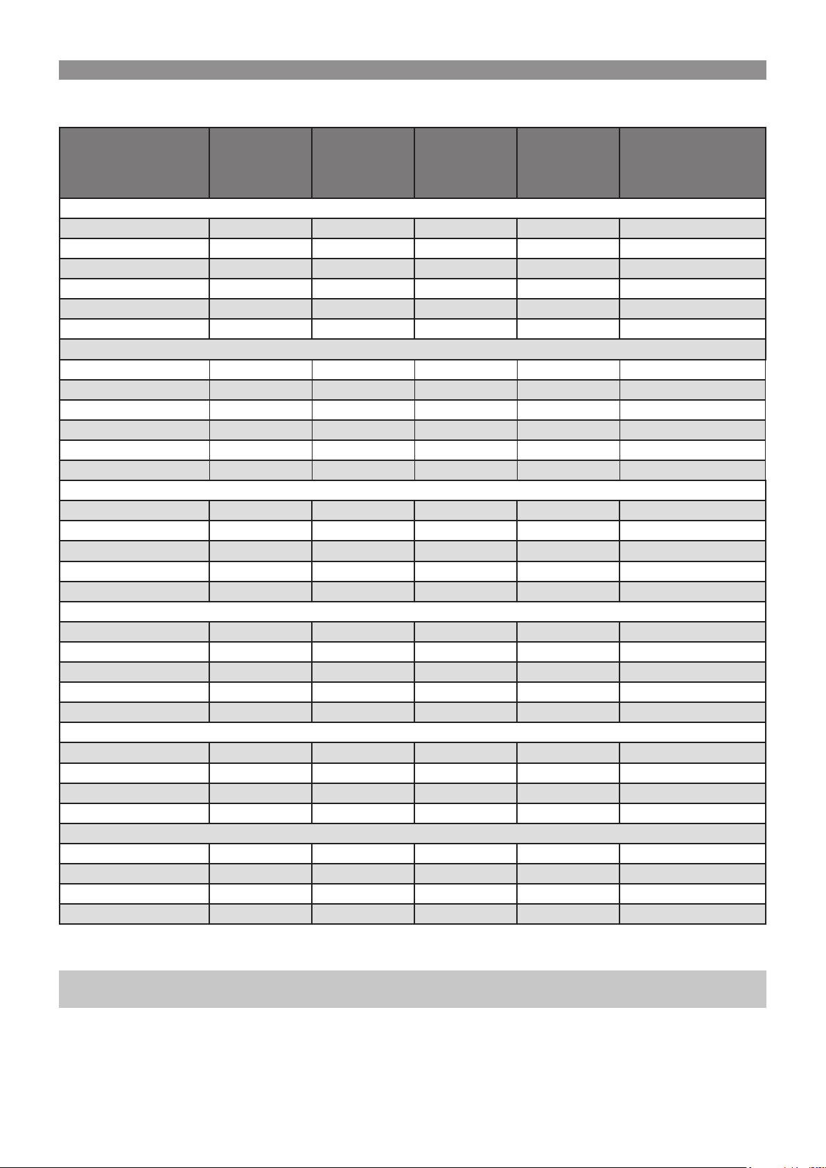
Table 9. Outlet Register Chart
A B C D
System Model
SP6 Heaters – Universal
SP615U 695 12 13 5 2
SP623U 733 12 13 5 2
SP623U XA 769 13 13 5 2
SP630U 1000 15 23 7 3
SP630U XA 1025 17 23 7 3
SP635U 1073 17 24 7 2.5
SP6 Heaters – Internal
SP615IN 695 12 13 5 2
SP623IN 765 12 13 5 2
SP623IN-XA 795 14 13 5 2
SP630IN 1065 16 22 7 3
SP630IN-XA 1095 17 22 7 3
SP635IN 1130 17 24 7 2.5
SP5 Heaters – Universal
SP521U 785 12 13 5 1.5
SP521U XA 830 14 13 5 1.5
SP530U 1045 16 24 7 2
SP530U XA 1108 17 24 7 2
SP535U 1133 17 24 7 2.5
SP5 Heaters – Internal
SP521IN 785 12 13 5 1.5
SP521IN-XA 830 14 13 5 1.5
SP530IN 1080 17 24 7 2
SP530IN-XA 1140 17 24 7 2
SP535IN 1160 17 24 7 2.5
SP4 Heaters – Universal
SP415U 620 10 12 6 2
SP421U 621 10 12 6 2
SP430U 918 16 23 7 2
SP435U 1004 17 23 7 3
BX5 Heaters – External
BX520EN (300mm)** 605 10 12 5 2
BX520EN (350mm)** 667 12 13 6 2
BX526EN (350mm)** 944 16 23 7 2
BX526EN (400mm)** 1011 17 23 7 3
Airflow Rate
(L/s)
** Model and base-box duct size
Maximum No.
Ceiling Outlets
Typical No.
Floor Outlets
Minimum No.
Floor/Ceiling
Outlets
(Adaptive Zoning)
Minimum No.
Floor/Ceiling Outlets
Note: For SP4, SP5 and SP6 installations, the normal return air pop configuration is side entry, but can be changed to the end of the
fan cabinet if necessary. Connecting the return air duct to the end of the unit reduces the rated airflow by up to 30%.
Rinnai 34 Ducted Gas Heater IM
Page 35

10. THERMOSTAT INSTALLATION
10.1 SP AND BX5 SERIES THERMOSTAT POSITIONING GUIDELINES
A thermostat is positioned inside the house and wired to the control module in the heater unit. The thermostat
monitors the temperature in the house and switches the system on and off in order to maintain a set temperature,
therefore, the thermostat must be installed in the correct position.
Various thermostats are available for controlling the heating systems; these are explained below.
It is important that the thermostat is placed in a position that will provide the most accurate reading of the temperature,
for example, in the area most often used for family living.
Note:
• Do not install the wiring with the power turned on, as the fuse may blow, which would not be covered under warranty.
• Use only thermostats of the same brand as the heater unit, as any failure relating to a non-matching thermostat will not be covered
under warranty.
Internal Wall
The temperature difference on an external wall can also affect the thermostat accuracy, so the thermostat should
always be mounted on an internal wall. Keep the hole in the wall for the wiring as small as possible to prevent
draughts from within the wall cavity affecting the temperature.
Height
The thermostat should be positioned approximately 1500mm above floor level.
Avoid Hot Spots
Keep the thermostat away from warm air outlets, such as radiation from the sun, fireplaces, radio and television sets,
and nearby warm pipes and ducts.
Avoid Cold Spots
Keep the thermostat away from draughts, such as from doorways, stairwells, windows and return air inlets.
Avoid Dead Spots
Keep the thermostat away from areas of less than normal air circulation, such as behind doors, in alcoves or in
corners.
Interference From Other Electrical Connections
Ensure the thermostat and control wiring are kept away from other electrical components, including electrical wiring,
data and antenna cables, and also the spark igniter loom within the heater cabinet.
Use the right cable
Ensure the cable is 0.75mm
2
in cross-section and less than 100m in length.
10.2 PROGRAMMABLE AND MANUAL THERMOSTAT INSTALLATION
Programmable and manual thermostats can be connected directly to SP and BX5 series heaters.
10.2.1 Connect a Programmable Thermostat
a. Run the wiring from the heater to the thermostat.
b. Remove the backing plate from the thermostat.
c. Draw the wires out from the wall cavity through the centre opening of the backing plate.
d. Mount the backing plate on the wall (before connecting the wires).
e. Connect heater terminals R and W to the respective R and W terminals on the thermostat (refer to Diagram 22
for an SP Series heater or Diagram 23 for BX5).
f. Fan only operation: Connect heater terminal G to terminal G on the thermostat.
g. Insert the batteries correctly and mount the thermostat onto the backing plate.
h. Refer to the installation guide and operating manual supplied with the programmable thermostat.
Rinnai 35 Ducted Gas Heater IM
Page 36
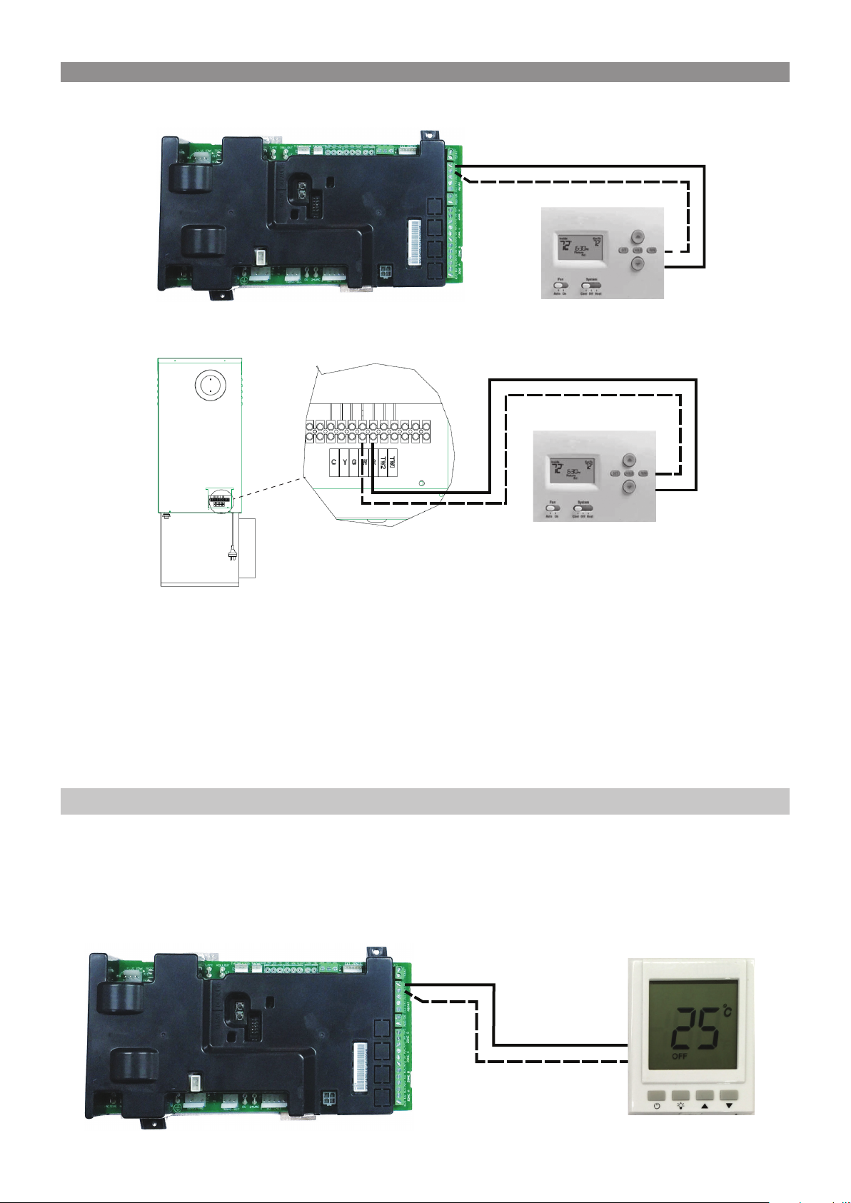
Diagram 22. SP Series Programmable Thermostat
Control Module
Programmable Thermostat
Diagram 23. BX5 Programmable Thermostat
W R
R
W
W
R
W
R
Programmable ThermostatBX5 Terminal Block
10.2.2 Connect a Manual Thermostat
Connect a manual thermostat as follows:
a. Select a suitable location for the thermostat (refer to Section 10).
b. Run the wiring from the heater to the thermostat.
c. Remove the thermostat front cover and connect the wires to thermostat terminals A and B.
d. Ensure the thermostat batteries are correctly installed and mount the thermostat level on the wall (refer to, and
follow, the installation guide supplied with the thermostat).
Note: Use only alkaline batteries as other types of battery can cause unpredictable operation as the batteries become depleted.
e. Install the thermostat front cover.
f. Connect the wiring to the heater at terminals R and W (refer to Diagram 24 for an SP Series heater or Diagram
25 for BX5).
g. For fan-only operation, wire a switch in circuit between heater terminals R and G.
Diagram 24. SP Series Manual Thermostat
R
W
SP Series Control Module
Rinnai 36 Ducted Gas Heater IM
Manual Thermostat
Page 37
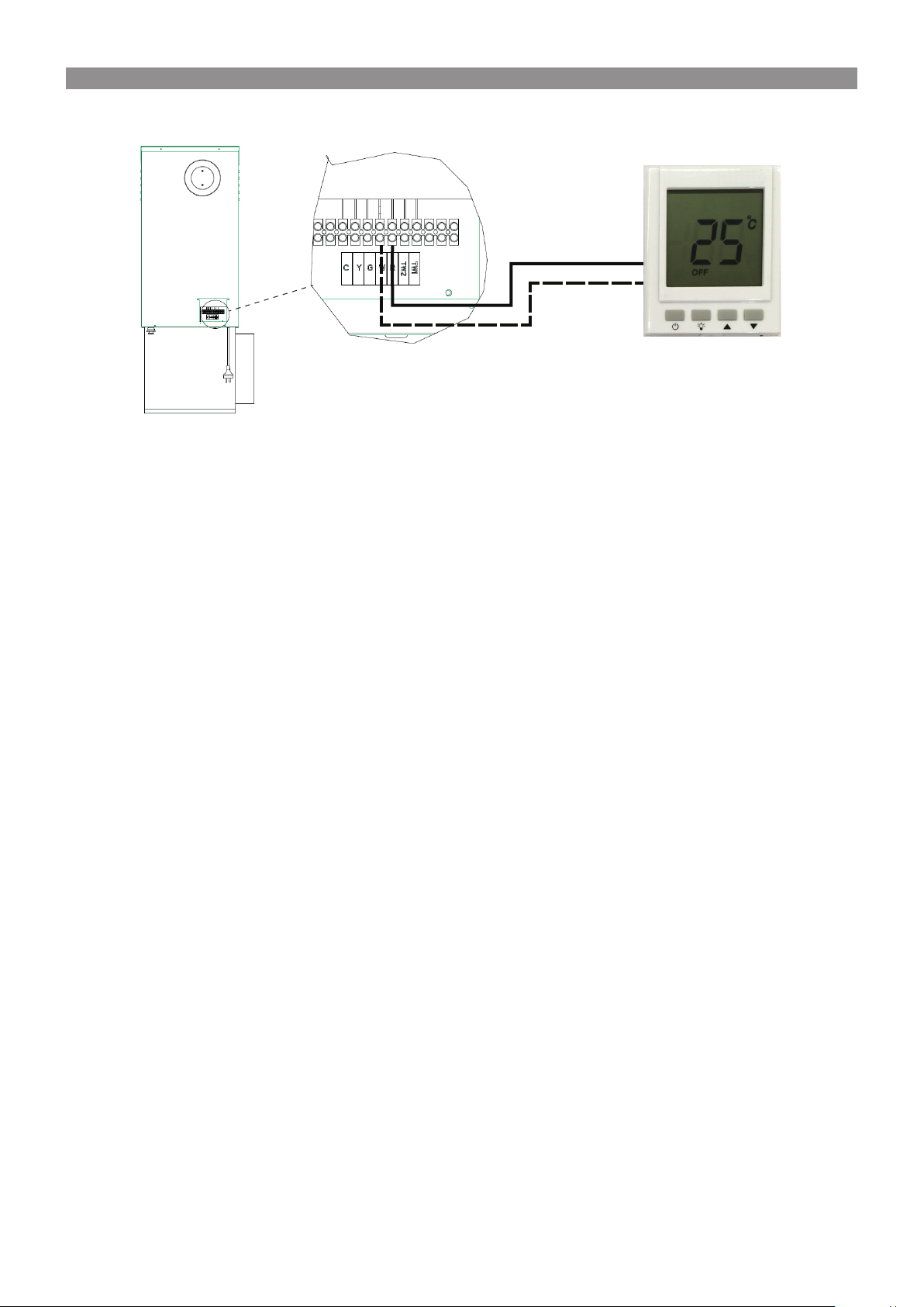
Diagram 25. BX5 Manual Thermostat
W R
Manual ThermostatBX5 Terminal Block
Rinnai 37 Ducted Gas Heater IM
Page 38
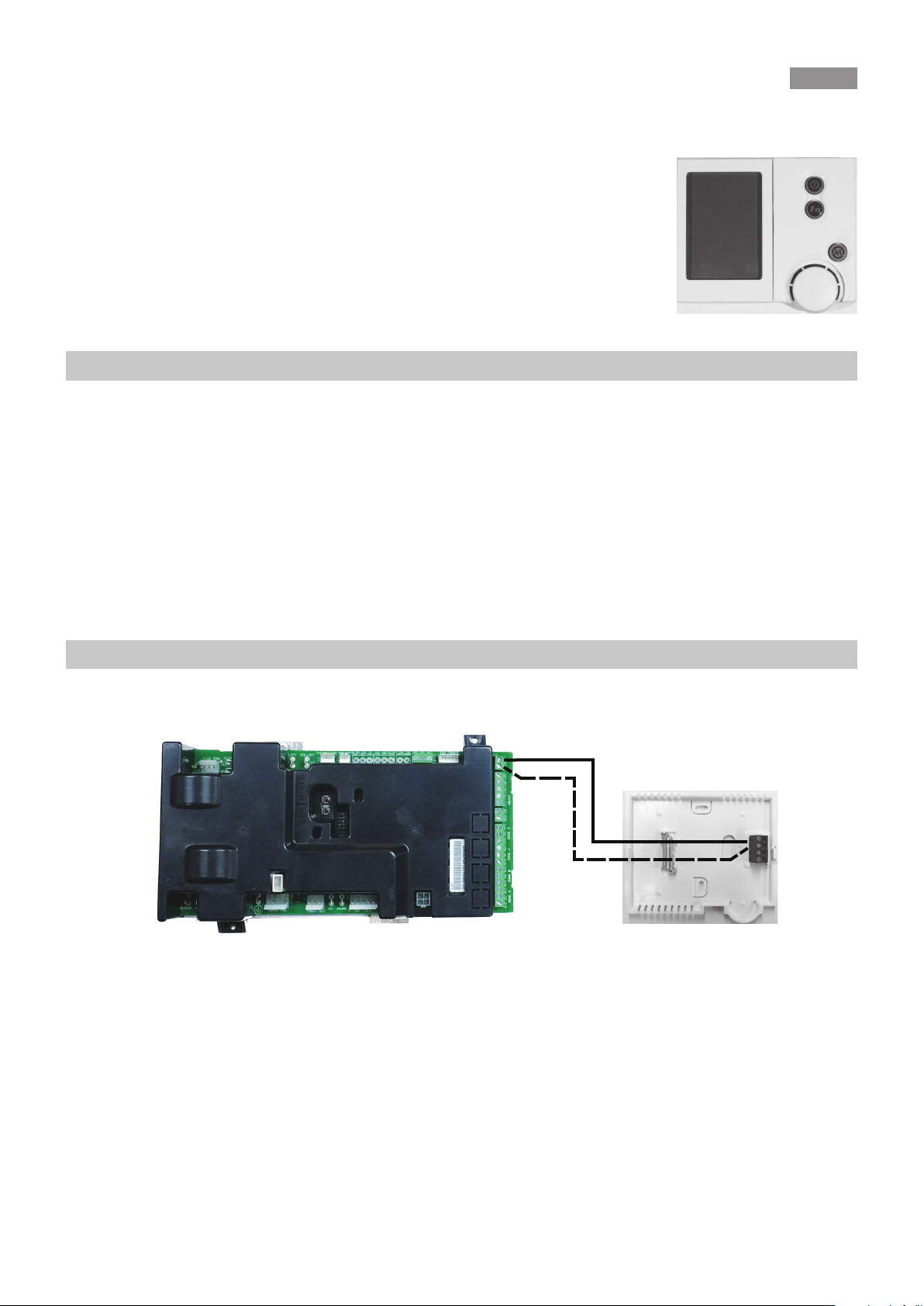
11. NETWORKER INSTALLATION: SINGLE AND
MULTIPLE CONNECTIONS
11.1 NETWORKER INSTALLATION
Networkers can be wired directly to SP and BX5 series heaters.
The networker backing plate has four terminal points for the connection of control wires.
When making the connections, use only the two top terminals marked TW1 and TW2
or the two bottom terminals also marked TW1 and TW2. Never use a combination of
terminals when connecting to a single appliance. For example, a networker operating a
cooler and a heater would have the two bottom terminals connected to the heater and
the two top terminals connected to the cooler.
Note: Always ensure that the TW1 and TW2 polarity is correct at both ends of all connections: TW1 to TW1 and TW2 to TW2.
11.2 CONNECT A NETWORKER TO SP OR BX5 SERIES HEATERS
a. Run a twin wire cable from the heater to the networker (for example, figure-eight cable, 0.75mm2).
b. Remove the backing plate from the networker by unclipping it at the sides.
c. Draw the wires from the wall cavity and feed them through the opening in the backing plate.
d. Connect the cable to the terminal connections on the backing plate before mounting it on the wall and
reassembling the networker.
e. Connect the other end of the cable to the terminals marked TW1 and TW2 in the heater’s electronic control
module, refer to Diagram 26.
Note: To connect multiple heaters, refer to Section 11.
Diagram 26. SP Series Networker Connections
TW1
TW2
TW1
TW2
SP and BX5 Series Control
Networker
Backing Plate
11.3 CONNECT A NETWORKER TO A BX5 HEATER
a. Run a twin wire cable from the heater to the networker (for example, figure-eight cable, 0.75mm²).
b. Remove the backing plate from the networker by unclipping it at the sides.
c. Draw the wires from the wall cavity and feed them through the opening in the backing plate.
d. Connect the cable to the terminal connections on the backing plate before mounting it on the wall and
reassembling the networker.
e. At the heater, access the terminal block by removing the cover panel.
f. Feed the cables through the grommet at the base of the unit to the heater terminal block.
g. Connect to TW1 and TW2 on the heater terminal block, refer to Diagram 27.
Rinnai 38 Ducted Gas Heater IM
Page 39
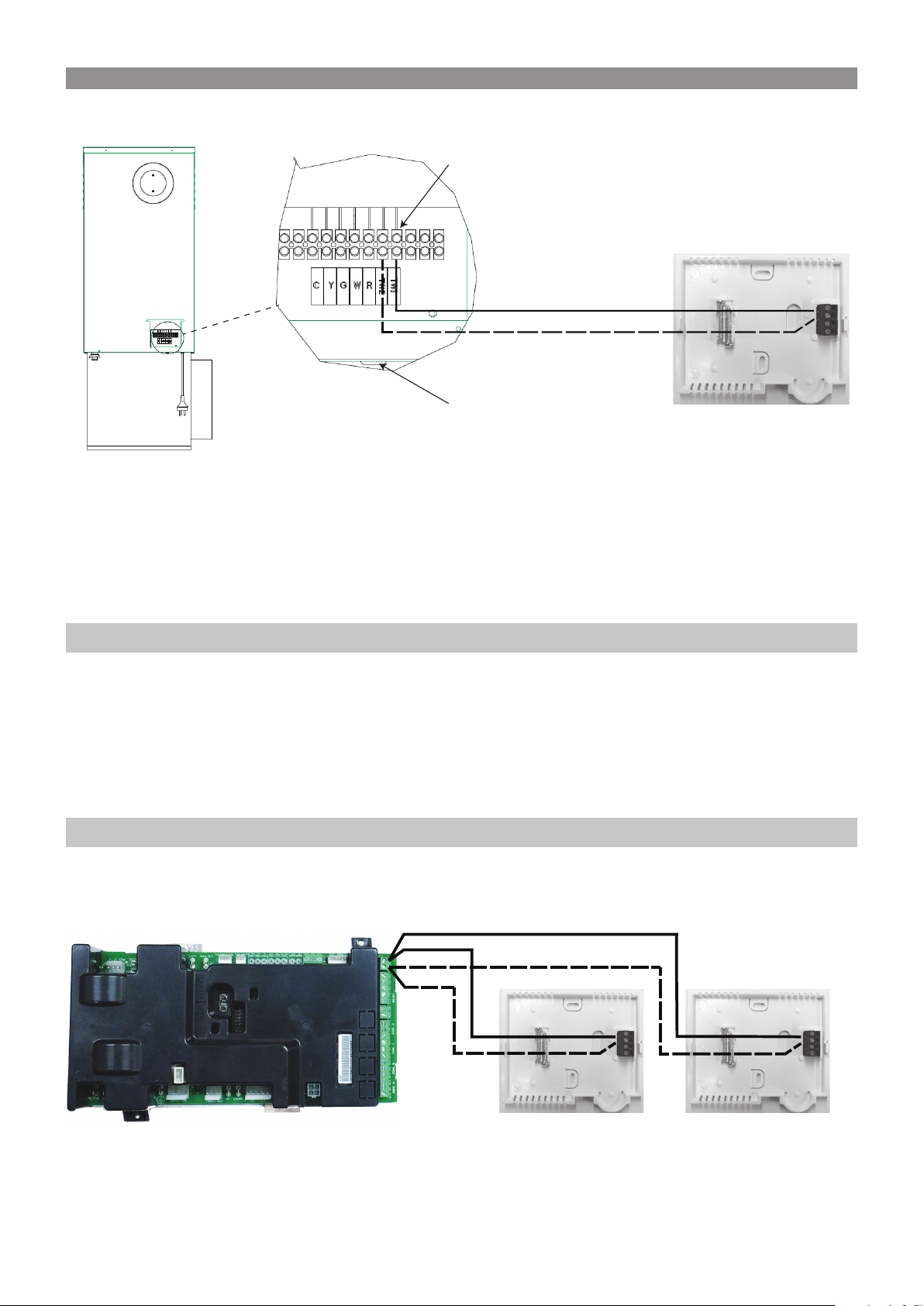
Diagram 27. BX5 Networker Connections
TERMINAL BLOCK
TW1
TW2
GROMMET
11.3.1 Connect Multiple Heaters to a Networker
Configure multiple heaters to the networker as follows:
a. Wire each heater to the network in parallel (refer to Diagram 28);
b. Assign a different identification number (address) to each heater, starting at '1' (refer to Section 13.1), and
c. Assign each heater to a zone (refer to the Network 516 Manual).
Note: The two networkers must be wired in parallel (not in series).
11.3.2 Connect Dual Networkers
Two networkers can be connected to a single SP series heater to provide dual controls. This is particularly useful
with adaptive zoning to enable dedicated zone control. For example, one networker can be used to control one zone,
while the other networker is used to control another zone.
Heater settings can be adjusted from either networker and will remain common to both networkers. That is, when a
heater setting is adjusted using one networker, the setting is immediately reflected on the other networker.
Note: A master networker can be identified by the word 'Clock' beside Key 5 (while the networker is switched off).
Diagram 28. Dual Networker Connections
TW1
TW2
TW1
TW2
TW1
TW2
SP and BX5 Series Control
Rinnai 39 Ducted Gas Heater IM
Master Networker
Backing Plate
Slave Networker
Backing Plate
Page 40
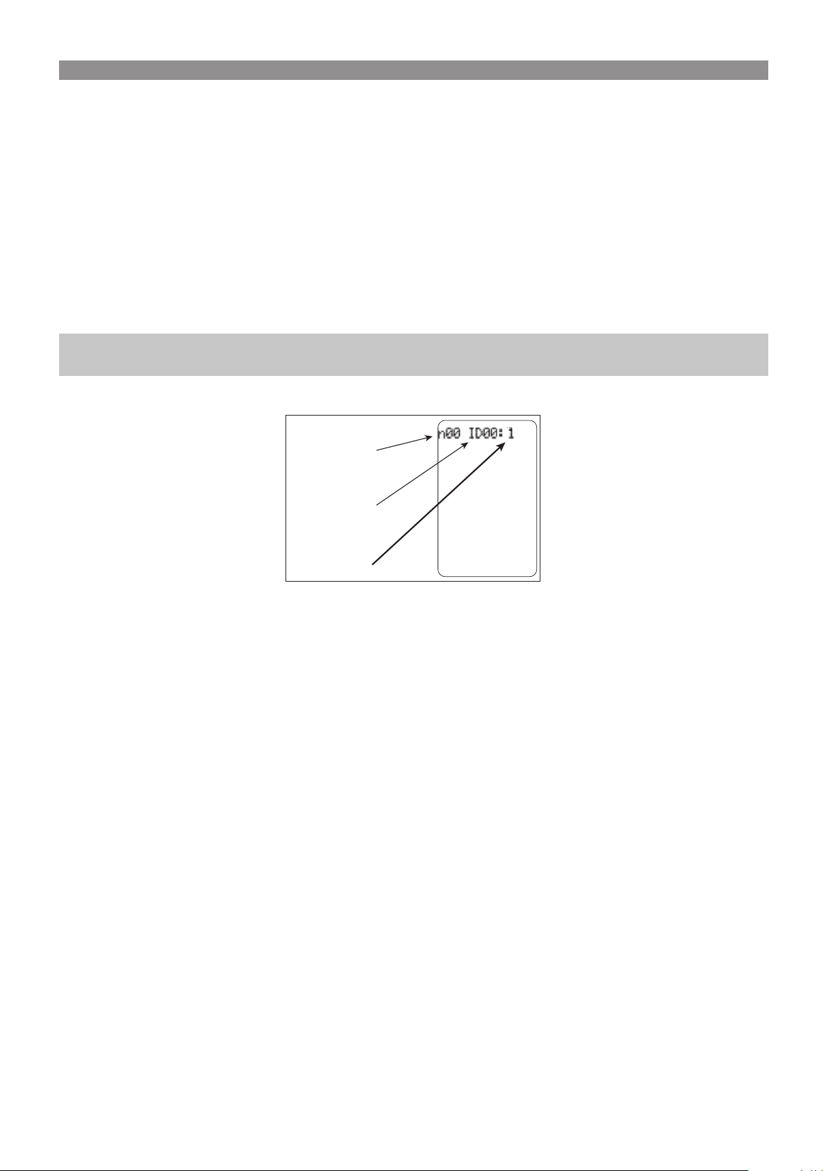
a. Mount the networkers (refer to para 11) and connect the wiring as shown in Diagram 28.
b. For a dual networker system to operate correctly, the networkers must be configured with one as master and one
as slave. Networkers are configured as master by default, so only the slave networker needs to be configured.
c. Determine which networker will be the master and which will be the slave.
d. Press Key 5 on the slave. 'Clock setting mode' displays. Confirm that the clock display is flashing.
e. Press and hold Key 2 and Key 4 until 'Installer parameter access' displays.
f. After the message clears, press the mode key (M) until 'n01 ID00:1' displays (refer to Diagram 29).
g. Turn the rotary dial to change 'ID00: #' to 'ID00: 1' (1 = master, 2 = slave).
h. Press the on/off button to save and exit.
Note: Installation parameters are not available from slave networkers. Therefore, after a networker is configured as a slave, the
master networker must be used to access the parameters.
Diagram 29. Networker Identication
Networker ID
Parameter
Value
11.3.3 Change a Networker from Slave to Master
a. Detach the networker from the backing plate. The controller powers down.
b. While continually pressing Key 3 and Key 5:
• mount the networker onto the backing plate, and
• wait until Set this Networker’s address! displays.
If the message does not display, repeat from Step a.
c. Turn the rotary dial to change 'ID00: #' to 'ID00: 1' (1 = master, 2 = slave).
d. Press the on/off button to save and exit.
11.3.4 Network 516 Manual
Refer to the Network 516 manual for further information about the following:
• Networker installation parameters
• Adaptive zoning
• Controlling multiple appliances with one networker
• Grouping multiple appliances into zones using one networker.
11.3.5 ZonePlus
Refer to the ZonePlus Installation Manual if installing a ZonePlus control system.
Rinnai 40 Ducted Gas Heater IM
Page 41
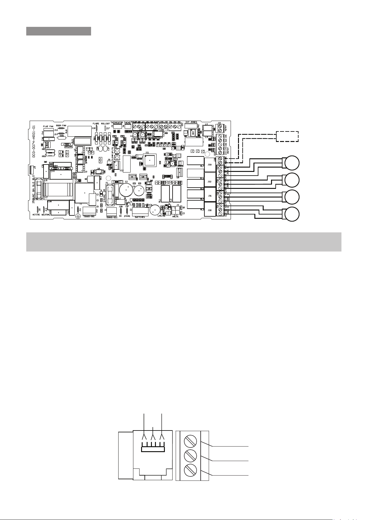
12. ADAPTIVE ZONING AND ADD-ON AIR
CONDITIONING
12.1 OPTIONS
SP universal and BX5 series heaters can be configured for zoning and/or add-on refrigerative air conditioning. There
are four 24 VAC relays on the PCB control module, which can be configured either for four zone motors, or for four
zone motors and an add-on refrigerative air-conditioning control, as shown in Diagram 30.
Diagram 30. Zoning/Add-on Connections - NG-3 PCB
24 VAC
ADD-ON
REFRIGERATION
24 VAC ZONE
D
DAMPER MOTOR
24 VAC ZONE
DAMPER MOTOR
C
24 VAC ZONE
B
DAMPER MOTOR
24 VAC ZONE
A
DAMPER MOTOR
Note: Refer to the Add-On Cooling brochure for further information. For ZonePlus configuration, please refer to the ZonePlus
Installation manual.
12.2 DAMPER MOTOR CONNECTIONS
All SP and BX5 series gas ducted heaters come with four RJ12 socket connectors preconfigured for Belimo®
24V damper motors.
RJ Socket Connections
The plastic cover on the PCB includes moulded cut-outs to enable access to the RJ12 socket. For each socket to
be used, press out and remove the cut-out and connect the RJ plug from the Belimo
If not a Belimo damper motor confirm suitability of the terminal on the damper motor before connecting to the RJ12
socket on the heater PCB. The RJ12 socket in Diagram 31 contains six terminal wires, the left two are connected
to Normally Open (N/O) on the 3-way terminal block, the middle two are connected to '0V', and the right two are
connected to Normally Open (N/C). Check the installation manual accompanying the damper motor to determine if
the RJ12 socket on the heater PCB is suitable.
Diagram 31. RJ12 socket detail on heater PCB
Diagram 31 details the Normally Closed (N/C), Zero Volt (OV) and Normally Open (N/O) connections for the RJ12
socket and terminal block connections for zones A, B, C and D on heater PCB.
®
damper motor.
N/O N/C
0V
N/C
0V
N/O
Rinnai 41 Ducted Gas Heater IM
Page 42
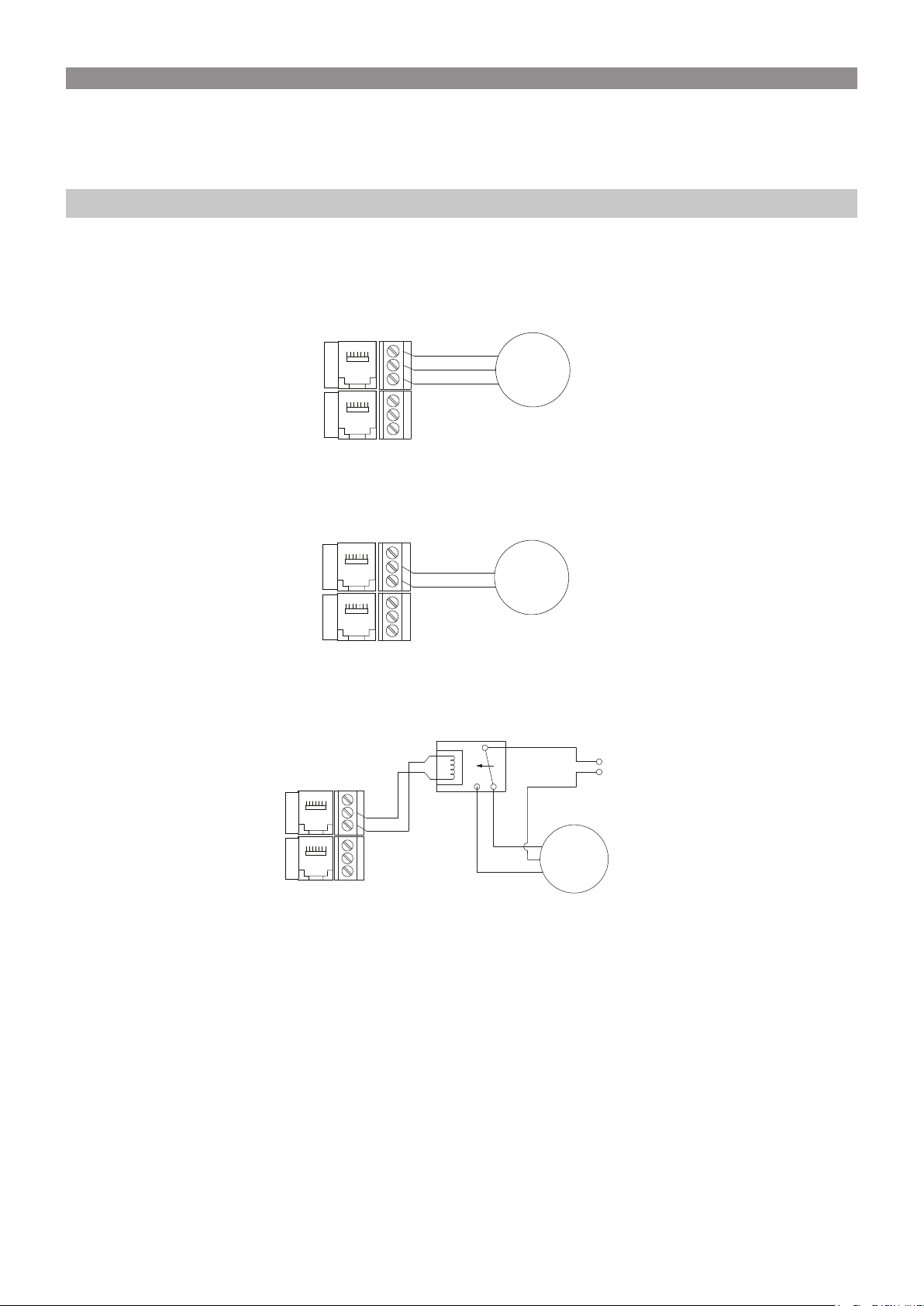
Three-way Terminal Connections
240VAC Relay
Diagram 32, Diagram 33 and Diagram 34 detail the Normally Open (NO), Normally Closed (NC) and zero volt (0V)
connections required to enable the networker outputs to control the damper motors.
Note: Ensure that the circuits are correct to Diagram 32, Diagram 33 or Diagram 34 as applicable.
12.3 CONNECT A DAMPER MOTOR TO THE CONTROL MODULE
Diagram 32. 24VAC Power Open/Power Close Damper Motor
RJ12
ZONE B
ZONE A
Connectors
N/C
0V
N/O
N/C
0V
N/O
Close
Common
Open
Damper Motor
24VAC
Power Open/
Power Close
Diagram 33. 24VAC Power Open/Spring Return Damper Motor
RJ12
Connectors
ZONE B
ZONE A
N/C
0V
N/O
N/C
0V
N/O
Active
Neutral
Damper Motor
24VAC
Power Open/
Spring Return
Diagram 34. 240VAC Power Open/Power Close Damper Motor
RJ12
Connectors
ZONE B
ZONE A
N/C
0V
N/O
N/C
0V
N/O
Close
Common
Open
240VAC Supply
Active
Neutral
Damper Motor
240VAC
Power Open/
Power Close
Rinnai 42 Ducted Gas Heater IM
Page 43
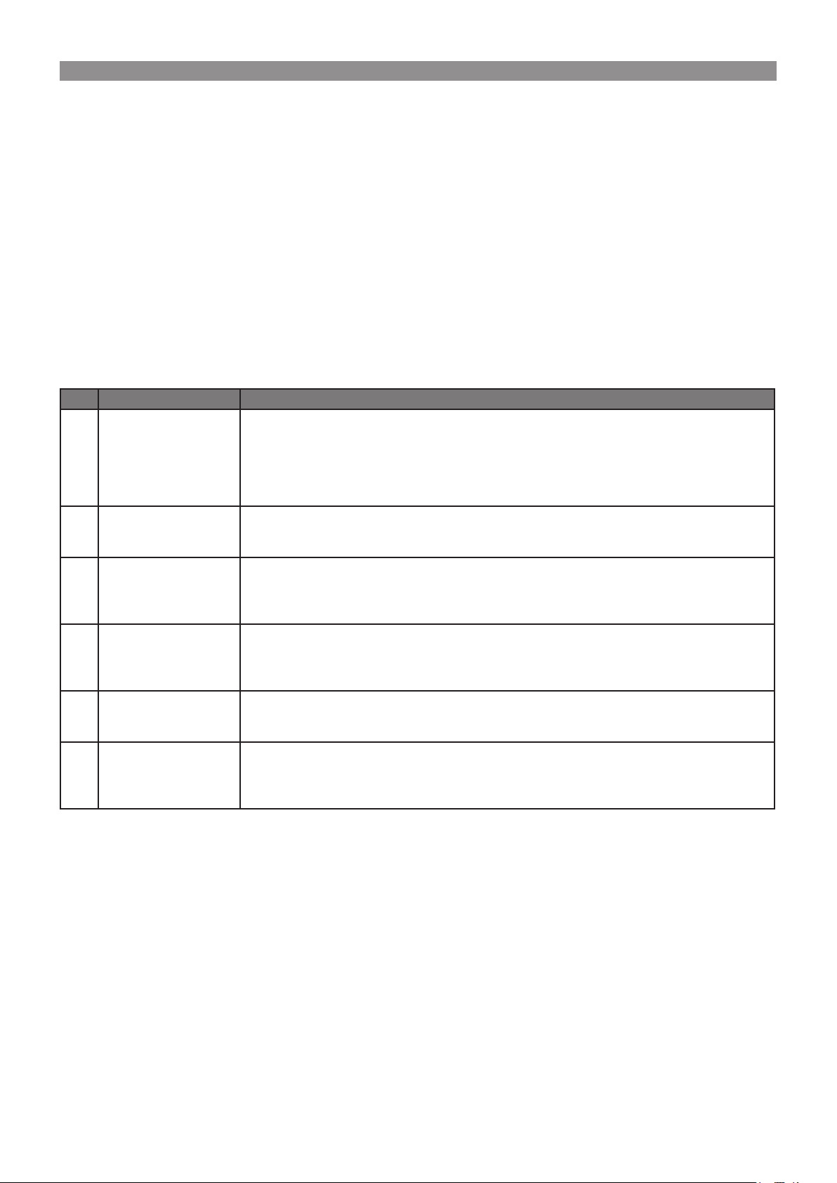
13. COMMISSIONING AND CONTROL SETTINGS
All of these heaters have been factory tested, but should be commissioned and adjusted in accordance with the
following instructions to ensure efficient and optimal heating performance. Remember:
• Mains power must be switched OFF before any wiring is touched.
• Commissioning must be carried out by a qualified trades person.
• If the heater cannot be adjusted to operate in accordance with these instructions, contact the Customer Service
Centre (refer to the back cover).
13.1 SP4, SP5, SP6 AND BX5 HEATER CONTROL SETTINGS
Heater settings (installer parameters) are adjusted via a networker controller. If dual networkers are configured,
either networker can be used to adjust the heater parameters.
Table 10. Heater Installer Parameters – SP4, SP5, SP6 and BX5
No. DISPLAY DESCRIPTION
1
H01 ID01: 1350
2
H01 ID02: 1350
3
H01 ID03: 950
4
H01 ID04: 1
5
H01 ID05: 500
6
H01 ID06: 65
HEATING: MAXIMUM FAN SPEED SETTING
The number displayed is the default fan speed setting. That is, the fan RPM setting for normal
heating operation. This setting can be adjusted from 500 to 1450 and should be set to meet
the installation airflow requirements. It is recommended that a fan speed of at least 1000 be
selected as lower speeds are more likely to result in overheating if the system has not been
balanced correctly.
COOLING: MAXIMUM FAN SPEED SETTING
The fan RPM setting for normal cooling operation. This setting can be adjusted from 500 to
1350.
HEATING: ZONING MINIMUM FAN SPEED SETTING
The minimum RPM to which the fan will operate with the maximum number of outlets closed,
with the networker zoning in heating mode. This setting can be adjusted from 500 to 1350
(default is 950).
HEATER IDENTIFICATION NUMBER
(Do not alter unless multiple heaters are installed)
In systems with multiple heaters installed, identifies each heater unit in priority order, for
example ID04: 1, ID04: 2, ID04: 3.
CIRCULATION FAN OPERATION
The fan RPM setting in circulation mode. That is, fan operation between heating or cooling
cycles when the set room temperature has been achieved.
SUPPLY AIR THERMISTOR SET POINT TEMPERATURE
The temperature that the heater gas valve modulates to maintain. This setting can be
adjusted from 45°C to 70°C (default setting varies between different models) and should be
set to provide a comfortable outlet temperature.
Rinnai 43 Ducted Gas Heater IM
Page 44
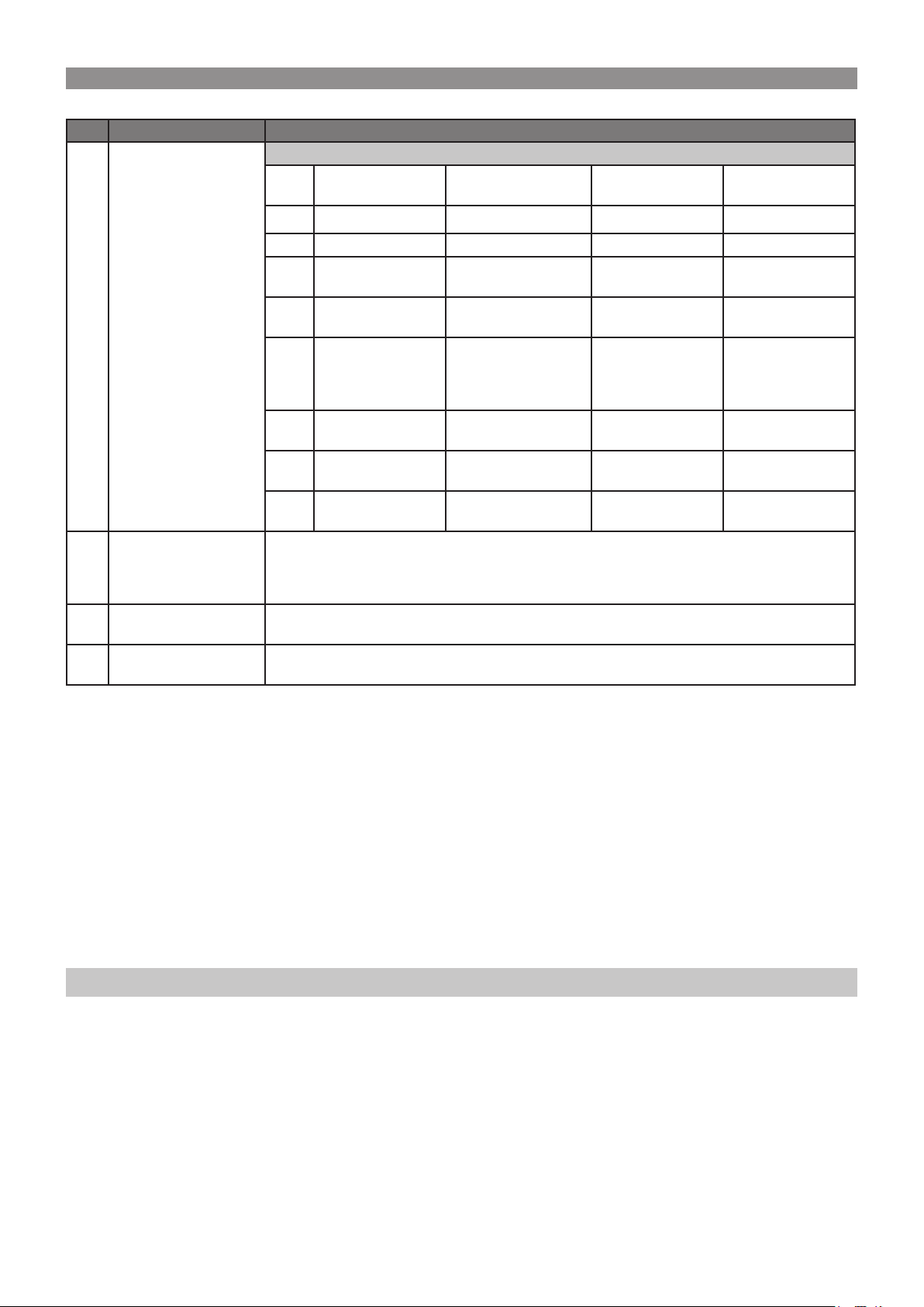
No. DISPLAY DESCRIPTION
7
H01 ID07: 0
8
H01 ID08: 1000
9
H01 ID09: 0
ZONE/REFRIGERATION /HUMIDIFIER MODE
Value System
Configuration
0
1 Heating Heater PCB – up to 4 N/A N/A
2
3
4
5
6
7
COOLING: ZONING MINIMUM FAN SPEED SETTING
The minimum RPM to which the fan will operate with the maximum number of outlets closed,
with the networker zoning in heating mode.
DO NOT SET BELOW 1000
DO NOT ADJUST
Heating N/A N/A N/A
Heating + Add-On Heater PCB – up to 4 Heater PCB
Heating +
Humidification
Heating +
Humidification +
Add-On
Heating Zone Module – up
Heating +
Add-On
Heating +
Add-On
Heater PCB – up to 4 N/A Heater PCB ‘ADD-
Heater PCB – up to 3
Zone
Connection
(A,B,C)
Zone Module – 1
only (D)
to 4
Zone Module – up
to 4
Zone Module – up
to 3
Add-On
Connection
‘ADD-ON’ terminal
Heater PCB
‘ADD-ON’ terminal
N/A N/A
Heater PCB
‘ADD-ON’ terminal
Zone Module
‘ADD-ON’ terminal
Humidifier
Connection
N/A
ON’ terminal
N/A
N/A
N/A
10
H01 ID10: 30
Damper motor Open/Close time can be adjusted between 5 and 240 seconds - factory default
30 seconds
Adjust Networker Parameters
Adjust heater parameters via a networker, as follows:
a. Press Key 5. 'Clock setting mode' displays. Confirm that the clock display is flashing.
b. Press and hold Key 2 and Key 4 until 'Installer parameter access' displays.
c. After the message clears, press the mode key (M) to toggle between networker parameters (n01), and heater
parameters (H01). If more than one networker or heater unit is configured in the system, repeatedly press the
mode key until the desired heater unit is selected, e.g. H01 ID01: 1.
d. Press Key 1 or Key 2 to scroll through, and select, the required parameter ID, e.g. H01 ID01: 1 (refer to Table
10). (Key 1 = next ID, Key 2 = previous ID.)
e. Turn the rotary dial to adjust the parameter value, e.g. H01 ID01: 1.
f. Press the on/off button to save and exit.
Note: All settings are saved automatically when the on/off button is pressed to exit networker set-up mode.
Rinnai 44 Ducted Gas Heater IM
Page 45

13.2 SP4, SP5, SP6 AND BX5 COMMISSIONING INSTRUCTIONS
13.2.1 Initial Damper Settings
Generally, a correctly designed and installed ducted system should have the following initial damper settings:
• Living areas: 100% open
• Bedrooms: 50% open
• Bathrooms, ensuite and laundry: 25% open.
13.2.2 Initial Ignition and Gas Inlet Pressure Check
a. Disconnect the power supply from the system at the power point.
b. Connect a networker to enable access to the heater installation parameters (refer to para 11).
c. Locate the inlet gas pressure test point and loosen the captive screw three full turns anti-clockwise. DO NOT
remove the screw.
d. Attach a manometer to the inlet gas pressure test point on the gas valve (refer to the label on the gas valve for
the test point location).
e. Purge air from the gas piping and turn on the gas at the supply tap.
f. Connect and switch on the 240V power supply at the power point.
g. Turn on the thermostat and set the temperature to maximum (see the Owner’s Manual for operating instructions).
Ensure that all zones (if any) are open. It should be possible to see the burners operating at the heater.
Note: If there is air in the gas line, the heater may not ignite on the first attempt. Ignition attempts will occur automatically. Allow time
for the heater to rectify itself as it may simply be purging air. If ignition is not successful, the heater will cease ignition attempts
and lock out with an error code. If this occurs, take note of the code and reset the heater (refer to the Operation manual).
Initially the fan will run at a low speed (approximately 500 RPM) and then to ramp up to the preset fan speed for
heating (refer to Table 10, Item 1).
h. Wait for the heater to operate for at least 1 minute and then measure the gas inlet pressure. While all other gas
appliances are operating at full capacity, the gas pressure must not, at any time, fall below:
• 1.1 kPa for NG models
• 2.7 kPa for LPG models.
If the pressure cannot be maintained above these measurements, then the incoming gas supply is
inadequate. Check the supply pipe for blockages, and check the gas pipe and meter sizing.
i. Switch off the heater, remove the manometer, and tighten the captive screw at the inlet gas pressure test point.
Note: DO NOT adjust the gas valve under any circumstances.
j. Ensure that the system is functioning correctly up to this point before continuing with the commissioning
procedure.
13.2.3 Heater Temperature Settings and Fan Speed
In this step, the heating settings are adjusted to suit the installation. These settings are critical to the provision of
adequate and efficient heating for the installation.
a. Access the heater control settings (refer to Section 13.1) and confirm that the thermostat is set much higher than
the current room temperature.
b. Set the fan speed (H01 ID01) to provide sufficient but not excessive airflow. (Typically, the fan speed is less for
floor outlet systems than for ceiling outlet systems.) The airflow from down-vent ceiling diffusers in main living
areas should be felt near floor level.
Rinnai 45 Ducted Gas Heater IM
Page 46

c. Do not adjust the thermistor set temperature unless the system is NOT achieving the following temperature rises:
• Ceiling outlets: 25º to 30ºC, and
• Floor outlets: 35º to 40ºC.
These temperatures are calculated by measuring the temperature at the closest outlet to the heater,
then subtracting the return air intake temperature. The difference should never exceed 45ºC.
For example, noting the maximum allowable floor outlet temperature rise is 40°C, with a return air intake
temperature of 20ºC, the closest floor outlet temperature rise must not exceed 60ºC.
Adjustments
If the desired temperature rise is too low or too high the following adjustments may be required.
a. Increase the room temperature setting to maximum to turn the heater on, then wait until the thermistor temperature
until it stabilises.
Ideally, the fan speed setting will be sufficient for the heater to operate at full capacity when all of the
outlets are open and balanced as described previously. The gas rate will then be maintained at the
maximum rate during the initial heating cycle and will decrease (modulate) only when the supply air
temperature is reached on subsequent heating cycles. This will initially allow the heater to increase the
house temperature at a faster rate to maintain the customer’s desired room temperature.
b. With a floor outlet system (which usually requires a low fan speed), as required adjust the thermistor set
temperature to achieve a 35º to 40ºC rise and avoid modulation. If the heater still reaches the thermistor set
temperature or the rise is greater than 40ºC, increase the fan speed.
c. With a ceiling outlet system (which usually requires a higher fan speed), if the heater reaches the thermistor
set temperature and modulates (this is unlikely), increase the thermistor set temperature and/or increase the fan
speed to achieve a 25º to 30ºC rise and avoid modulation.
If the temperature rise is above 40ºC, investigate the reason. It may be due to the following:
• A low number of outlets on the system.
• Restrictive or poorly balanced ductwork.
• An oversized heater for the installation.
• Inadequate fan speed.
• Inadequate thermistor set point.
Adaptive Zoning
Systems that have zone damper motors operated from a networker (adaptive zoning) require the zone minimum
fan speed to be set to suit the duct system. This ensures optimum performance from the adaptive zoning functions
within the heater. Set the zone minimum fan speed as follows:
a. Using the networker, close all but one zone.
• If the system does not have a common zone, select and turn on only the zone key that operates
the least number of outlets (ensure this zone does not have less than the minimum number of
outlets required for the heater size).
• If the system has a common zone then all zone keys can be turned off.
b. Adjust the EHTG fan speed setting (H01 ID03) to provide the required amount of air through the remaining open
outlets, ensuring that the temperature rise does not exceed 45ºC. Do not adjust the thermistor set temperature
while setting up the EHTG fan speed.
Rinnai 46 Ducted Gas Heater IM
Page 47
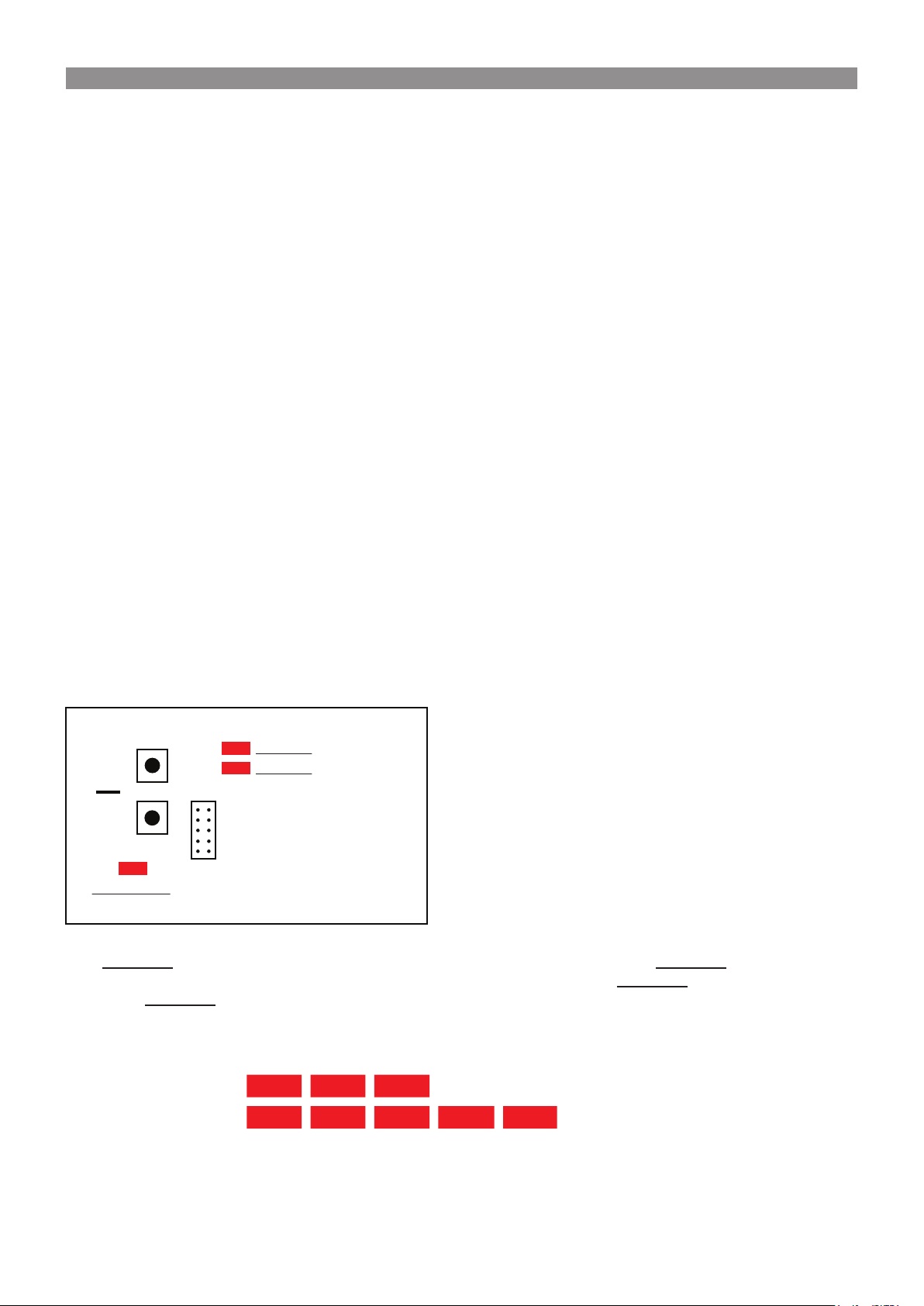
13.3 FINAL CHECKS (SP4, SP5, SP6 AND BX5 HEATERS
)
a. Check the temperature rise at the outlets. The temperature of the warm air at any outlet should not be more than
45ºC above the return air temperature. If it is, the heater will be approaching an overheat condition.
b. Check that the fan continues to run while the gas burner is operating.
c. Check that the fan operates in fan-only mode by operating the networker in fan-only mode (refer to the Owner's
Manual).
d. Ensure that the required gas inlet pressure is supplied at all times during heater operation (including when all
other gas appliances are operating at full capacity).
e. Ensure that the heater is switched off.
f. If the manometer still connected, turn off the gas supply at the supply tap, remove the manometer and tighten
the captive screw at the inlet gas pressure test point.
g. Turn on the gas supply at the supply tap and test for leaks using a soapy water solution or leak detector spray.
h. Install the heater top panel.
i. Instruct the customer on the correct operation of the system.
j. Issue any required documentation to the relevant people/authorities in regard to the installation of the heater,
the gas connection and the power supply. (For example, a Certificate of Compliance and Certificate of Electrical
Safety.)
13.4 FAULT CODE IDENTIFICATION ON HEATER PCB
If the heater fails to start the fault may display on the heater control board with a dual L.E.D flash sequence. The
two L.E.D’s that display the fault code are ‘PRIMARY STATUS L.E.D 1’ and ‘PRIMARY STATUS L.E.D 2’. Refer to
Diagram 35 for location of these status L.E.D’s in reference to the ‘CLEAR’ and ‘DEFAULT’ buttons on the heater
control board cover.
Diagram 35. NG-3 L.E.D identication
PRIMARY STATUS L.E.D 1
PRIMARY STATUS L.E.D 2
CLEAR DEFAULTS
SECONDARY
STATUS L.E.D
The ‘PRIMARY STATUS L.E.D 1’ shows the first digit (tens) of the fault code and ‘PRIMARY STATUS L.E.D 2’
shows the second digit (ones), e.g. fault code 35 would display as 3 flashes on ‘PRIMARY STATUS L.E.D 1’ and 5
flashes on ‘PRIMARY STATUS L.E.D 2’.
Both L.E.D’s will flash together for the first three flashes and then ‘PRIMARY STATUS L.E.D 1’ will stop while
‘PRIMARY STATUS L.E.D 2’ will flash two more times, example flash sequence below.
Primary Status L.E.D 1
Primary Status L.E.D 2
Rinnai 47 Ducted Gas Heater IM
Page 48
Some error codes that may be encountered during installation are detailed in Table 11 below.
Table 11. Error codes associated with installation
Fault Code Primary L.E.D 1
Flashes
30 3 0 Fan Limp Mode
35 3 5 Supply Air Thermistor Fault
36 3 6 Bad Supply Air Thermistor Location
40 4 0 Return Air Overheat
41 4 1 Supply Air Overheat
48 4 8 Pressure Lost
60 6 0 Motor Open Circuit
69 6 9 Fuse Blown 24Vac 2A
50 5 0 Ignition Lockout
51 5 1 Rollout No Gas
54 5 4 Rollout Lockout
56 5 6 Pressure Switch Stuck Open
57 5 7 Pressure Switch Stuck Closed
58 5 8 Pressure Switch Fail
Primary L.E.D 2
Flashes
Description
To reset the appliance and clear a lockout fault press and hold the ‘CLEAR’ button for three seconds on the heater
control board or reset through a Networker controller if connected.
Note: Assist the customer with filling in the Warranty Details on the company website:
http://www.rinnai.com.au or www.brivis.com.au and follow the links.
Rinnai 48 Ducted Gas Heater IM
Page 49
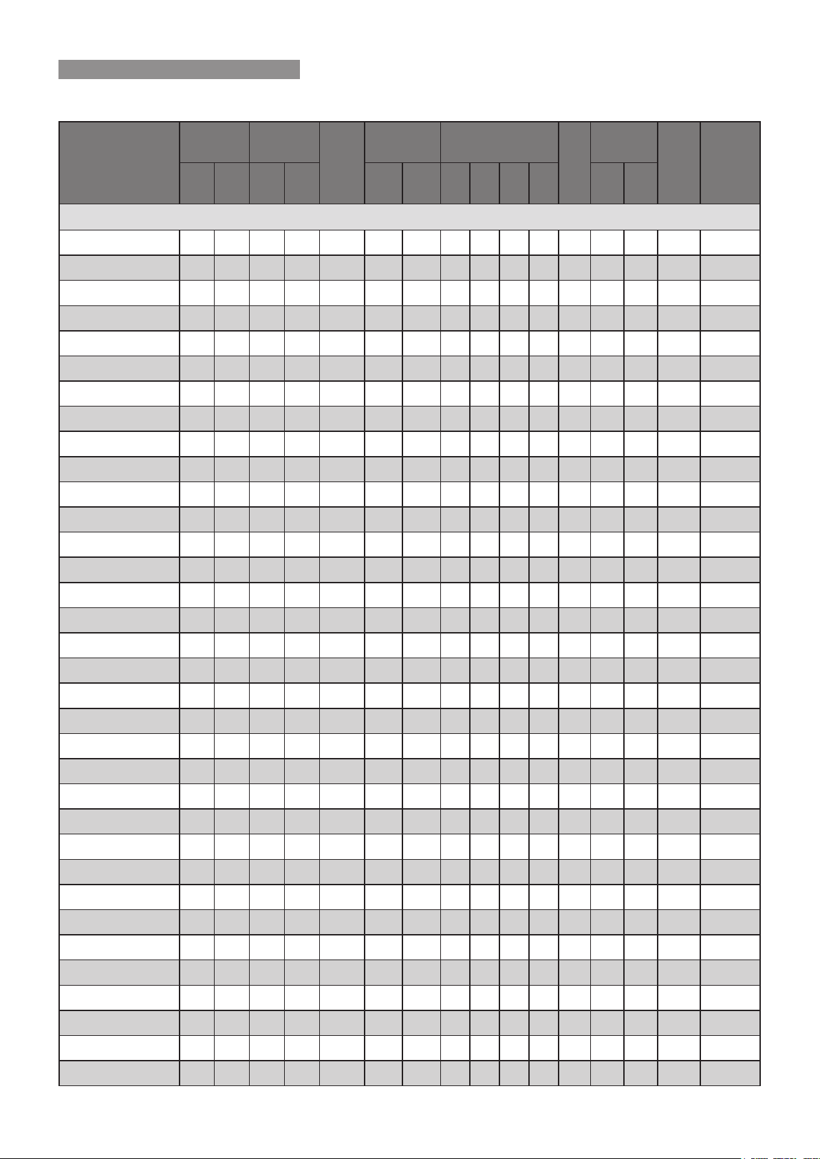
14. TECHNICAL SPECIFICATIONS
Table 12.
Minimum
Recommended
Return Opening
No Filter
With Filter
(m²)
Airflow @ Total Static Pressure
50 Pa 75 Pa 100 Pa 125 Pa
(m²)
(L/s)
Weight
(kg)
Fan Motor
Power
(W)
Current
(A)
Total
Maximum
Current (A)
Maximum
Recommended
Add-On Cooling
Capacity
Models
Gas Input
Max
Input
NG
MJ/hr
ULPG
Max
Input
Heat Output
Max
Output
NG
kW
Max
Output
ULPG
Duct
Connection
Pop Sizes
(mm)
Universal
SP615UN (Internal) 58 N/A 14 N/A 300 0.26 0.39 695 665 630 595 62 315 4.2 6 10
SP615UN (External) 58 N/A 14 N/A 300 0.26 0.39 655 625 590 555 62 315 4.2 6 10
SP623UN (Internal) 86 N/A 23 N/A 300 0.26 0.39 733 709 683 658 64 315 4.2 6 13
SP623UN (External) 86 N/A 23 N/A 300 0.26 0.39 693 670 640 609 64 315 4.2 6 13
SP623UN XA (Internal)
SP623UN XA (External)
SP630UN (Internal)
SP630UN (External)
SP630UN XA (Internal)
SP630UN XA (External)
SP635UN (Internal)
SP635UN (External)
+
86 86 23 23 350 0.28 0.42 769 745 723 696 64 315 4.2 6 15
+
86 86 23 23 350 0.28 0.42 734 710 684 655 64 315 4.2 6 13
+
+
+
+
110 110 29 29 350 0.36 0.54 1070 1050 1025 1000 86 650 4.3 6 18
110 110 29 29 350 0.36 0.54 963 934 900 865 86 650 4.3 6 18
+
110 110 29 29 400 0.38 0.57 1120 1088 1055 1025 86 650 4.3 6 18
+
110 110 29 29 400 0.38 0.57 1060 1028 996 963 86 650 4.3 6 18
129 129 35 35 450 0.39 0.58 1155 1130 1103 1073 86 650 4.3 6 22
129 129 35 35 450 0.39 0.58 1065 1030 985 940 86 650 4.3 6 18
(kW)
SP521UN (Internal) 90 N/A 21 N/A 300 0.26 0.39 785 765 740 715 61 315 4.2 6 13
SP521UN (External) 90 N/A 21 N/A 300 0.26 0.39 700 675 645 615 61 315 4.2 6 13
SP521UN XA (Internal) 90 N/A 21 N/A 350 0.28 0.42 830 800 770 735 61 315 4.2 6 15
SP521UN XA (External) 90 N/A 21 N/A 350 0.28 0.42 740 710 685 655 61 315 4.2 6 13
SP530UN (Internal) 130 N/A 30 N/A 350 0.36 0.54 1145 1113 1078 1045 80 650 4.3 6 18
SP530UN (External) 130 N/A 30 N/A 350 0.36 0.54 997 965 929 893 80 650 4.3 6 18
SP530UN XA (Internal) 130 N/A 30 N/A 400 0.38 0.57 1194 1165 1138 1108 80 650 4.3 6 18
SP530UN XA (External) 130 N/A 30 N/A 400 0.38 0.57 1025 1000 973 943 80 650 4.3 6
SP535UN (Internal) 150 N/A 35 N/A 450 0.39 0.58 1228 1194 1164 1133 80 650 4.3 6 22
SP535UN (External) 150 N/A 35 N/A 450 0.39 0.58 1078 1040 1005 968 80 650 4.3 6 18
SP415UN (Internal) 65 N/A 14 N/A 300 0.26 0.39 620 585 555 530 65 315 4.2 6 10
SP415UN (External) 65 N/A 14 N/A 300 0.26 0.39 583 550 522 498 65 315 4.2 6 10
SP421UN (Internal) 90 N/A 21 N/A 300 0.26 0.39 620 585 555 530 65 315 4.2 6 10
SP421UN (External) 90 N/A 21 N/A 300 0.26 0.39 583 550 522 498 65 315 4.2 6 10
SP430UN (Internal) 130 N/A 30 N/A 350 0.31 0.47 1010 984 953 918 84 650 4.3 6 15
SP430UN (External) 130 N/A 30 N/A 350 0.31 0.47 919 895 867 835 84 650 4.3 6 15
18
SP435UN (Internal) 150 N/A 35 N/A 400 0.36 0.54 1098 1068 1041 1004 84 650 4.3 6 18
SP435UN (External) 150 N/A 35 N/A 400 0.36 0.54 988 961 937 904 84 650 4.3 6 17
BX520EN (300mm)** 82 N/A 20 N/A 300 0.26 0.39 604 576 545 519 57 315 4.2 6 -
BX520EN (350mm)** 82 N/A 20 N/A 350 0.26 0.39 667 631 609 582 57 315 4.2 6 10
BX526EN (350mm)** 125 N/A 30 N/A 350 0.36 0.54 1026 998 972 944 67 650 4.3 6 -
BX526EN (400mm)** 125 N/A 30 N/A 400 0.36 0.54 1099 1069 1042 1011 67 650 4.3 6 18
Rinnai 49 Ducted Gas Heater IM
Page 50
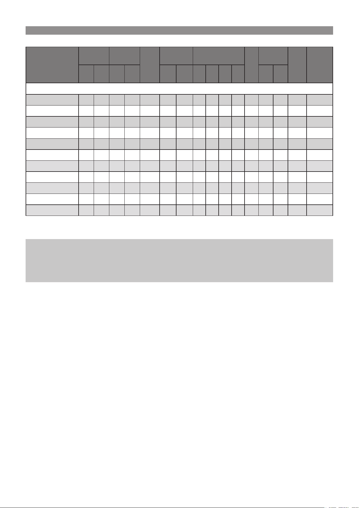
Minimum
Recommended
Return Opening
No Filter
With Filter
(m²)
Airflow @ Total Static Pressure
50 Pa 75 Pa 100 Pa 125 Pa
(m²)
(L/s)
Weight
(kg)
Fan Motor
Power
(W)
Current
(A)
Total
Maximum
Current (A)
Maximum
Recommended
Add-On Cooling
Capacity
(kW)
Models
Gas Input
Max
Input
NG
MJ/hr
Max
Input
ULPG
Heat Output
Max
Output
NG
kW
Max
Output
ULPG
Duct
Connection
Pop Sizes
(mm)
Internal
SP521IN 90 N/A 21 N/A 300 0.26 0.39 785 765 740 715 53 315 4.2 6 13
SP521IN XA 90 N/A 21 N/A 350 0.28 0.42 830 800 770 735 53 315 4.2 6 15
SP530IN 130 N/A 30 N/A 350 0.36 0.54 1170 1140 111 0 1080 71 650 4.3 6 18
SP530IN XA 130 N/A 30 N/A 400 0.38 0.57 1220 1195 1170 1140 71 650 4.3 6 18
SP535IN 150 N/A 35 N/A 450 0.39 0.58 1245 1215 1190 1160 72 650 4.3 6 22
SP615IN 58 N/A 14 N/A 300 0.26 0.39 695 665 630 595 57 315 4.2 6 10
+
SP623IN
SP623IN XA
SP630IN
SP630IN XA
SP635IN
+
+
+
+
ULP capacities are based on propane. All UPG units are compatible with butane/propane blends.
** Model and base duct size
+
ULPG models
86 N/A 23 23 300 0.26 0.39 765 745 720 695 59 315 4.2 6 13
86 86 23 23 350 0.28 0.42 795 775 755 730 59 315 4.2 6 13
110 N/A 29 29 350 0.36 0.54 1125 1110 1085 1065 72 650 4.3 6 18
110 110 29 29 400 0.38 0.57 1165 1145 1120 1095 72 650 4.3 6 18
129 129 35 35 450 0.39 0.58 1205 1180 1185 1130 76 650 4.3 6 22
Note:
• The manufacturer reserves the right to change specifications without notice.
• Rated air flow of universal units is in the factory default 'internal' configuration.
• Internal units in 'lay down' position reduces rated airflow by up to 30%
Rinnai 50 Ducted Gas Heater IM
Page 51

NOTES
Rinnai 51 Ducted Gas Heater IM
Page 52
by
Rinnai has a Service and Spare Parts network with personnel
who are fully trained and equipped to give the best service on
your Rinnai appliance. If your appliance requires service,
please call our National Help Line. Rinnai recommends that this
appliance be serviced at least every 2 years.
With our policy of continuous improvement, we reserve the
right to change, or discontinue at any time, specifications or
designs without notice.
Australia Pty. Ltd.
ABN 74 005 138 769
100 Atlantic Drive
Keysborough, Victoria 3173
P.O. Box 460
Braeside, Victoria 3195
AU45204
Product Sales & Service National Help Line
Tel: 1300 555 545* Fax: 1300 555 655
*
Monday to Friday, 8.00am to 5.30pm EST
For further information visit www.rinnai.com.au
or email [email protected]
B064403 Ducted Gas Heater IM Issue D February 2019
 Loading...