

Page 1

Vr1
Replacement Brake Adjuster
Kit Fitting Instructions
Br
itpart, The Grove, Craven Arms, Shropshire, SY7 8DA United Kingdom
Tel: +44 (0) 1588 672711 Fax: +44 (0) 1588 672660
Email: [email protected] www.britpart.co.uk
Part Number
RTC3176
MPK 1, 2, 3 & 4
Instructions (Eccentric type only)
1. ‘On the vehicle’ repairs can be best attempted by tilting
the front wheels as high as possible before removing road
wheels and brake drums. This initial positioning of the vehicle
will eliminate unnecessary cramped working conditions and
allow accurate adjuster replacement.
2. After ensuring that vehicle is properly supported,
handbrake and wheel chocks applied, remove road wheel(s)
and brake drum(s).
3. Carefully remove brake shoes and springs (noting the
relative position of all items removed to aid reassembly) and
wire up brake cylinder pistons.
4. Use small brush and vacuum cleaner to remove asbestos
dust from all areas of backplate.
WARNING
DO NOT ATTEMPT TO BLOW DUST OFF BACKPLATE.
INHALED ASBES
T
OS DUS
T C
AN BE HARMFUL TO HEAL
TH
5. Hacksaw off as much of the old adjuster as possible,
taking care not to damage the backplate or wheel cylinders
in the process.
6. Using a centrepunch, mark the precise centre of the
remaining part of the adjuster and drill through using
1
/4
and 3/4 dia dr
ills t
aking car
e not to damage the backplate.
F
inally remove the old adjusters with a sharp chisel.
7. Af ter removal of the old adjusters, clean areas around
holes in backplate on both sides, removing all traces of
cor
r
osion and any burr
ed edges so that the backplate is
smoo
th and flat. Make sure that the backplate in also free
from saw and drill swarf. THE BACKPLATE IS NOW READY
FOR INSERTION OF THE NEW ADJUSTERS.
GAUGING
8a. Using up to a maximum of three shim washers (4) space
t
he loc
k r
ing through the backplate (3) so that the inside
f
ace of t
he lock ring (5) is flush or slightly below the inside of
the inside face of the backplate (3).
N.B. It may only be necessary to use two shim washers (4)
although, dependant on backplate (3) thickness, it is possible
for no shim washers (4) to be required at all at this stage.
IMPORTANT
8b. If when using the maximum of three shim washers (4)
t
he inside face of the lock ring (5) is still proud of the
backplate (3) it will be necessary to file off any excess from
the face of the lock ring (5) (with the three shim washers in
position) until the flush condition is achieved.
9. When the correct number of shim washers has been
determined (this may differ between adjusters on the same
backplate) ADD ONE MORE SHIM WASHER to this number
and loosely assemble the complete adjuster through the
backplate.
10. Ensure that the Belleville washer (2) is assembled. Place
a
1
/4 square brake adjuster spanner on the new peg, and
ensuring that the lock ring (5) has entered cleanly through
the shim washers (4) and the hole in the backplate (3) begin
to tighten the lock nut (6) with
9
/16 A/F spanner. This will
dr
iv
e t
he lock ring onto the splines of the brake adjustor
body and flatten the Belleville washer against the backplate.
N.B. When the job is being tackled ‘on the vehicle’ there may
be some instances where it is difficult to use the spanners
as directed above. In these cases it is permissible to grip the
adjuster body (not the peg) on the brake drum side to
prevent turning whilst tightening the locknut.
IMPOR
TANT
Make sure the brake adjuster body is clear of turning stop in
t
he bac
kplate when tightening lock-nut.
1
1
. Continue t
o tight
en loc
knut until a stiffness of 2-3 lb ft
t
or
q
ue is required to turn new brake adjuster, smoothly, in
backplate with a
1
/4 square brake adjusting spanner. 2-3 lb
ft torque is approx, equivalent to a spring balance reading of
between 4 and 6 lb when hooked through the loose end of
brake adjuster spanner.
New brake adjuster is now fitted.
12. Repeat operations on remaining adjusters.
13. Reassemble brake shoes and springs (remembering to
remove lock wire from, brake cylinder pistons) and replace
brake drums. Adjust brakes.
14. Replace road wheels and road test. Make further
adjustments as necessary
N.B Please read through instructions before commencing work on vehicle. Always use the correct
spanners, otherwise ‘rounding off’ of the adjuster peg will result.
List of items required:
1
/4 square brake adjusting spanner; Hammer; Small sharp chisel; Electric drill and 1/4 and 3/4 dia drills
(sharp);
9
/16 A/F combination spanner; Centrepunch; Hacksaw; Wheel nut spanner; Posidrive screwdriver;
Ramps or jacks; Wheel chocks; Vacuum cleaner; Small brush; Clean wiper
Page 2
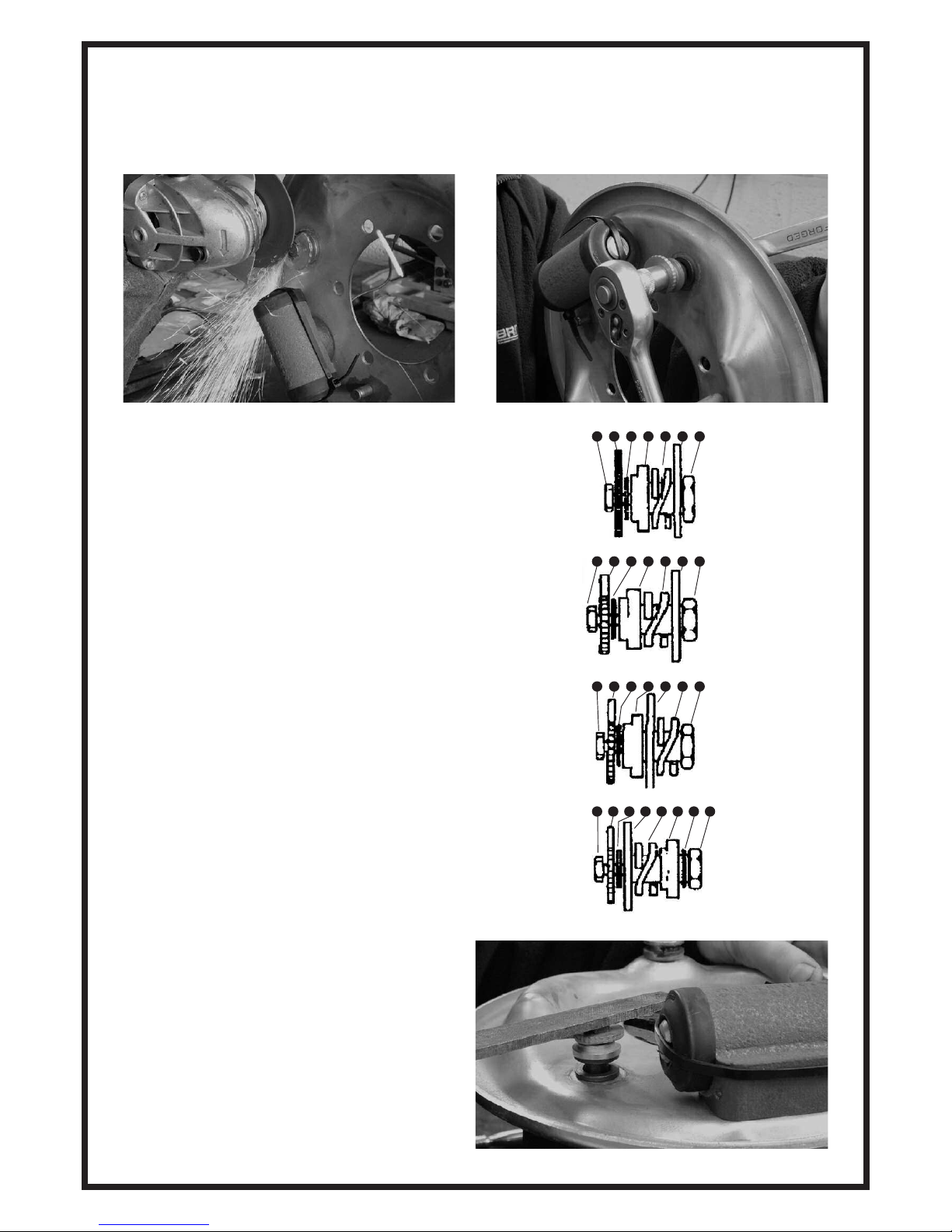
This kit services front and rear on all short wheel base models
and either front or rear on all long wheel base models.
1. Fitting Instructions – All models
Remove brake drum, shoes and springs, wire up brake cylinder
pistons. Lever, saw, chisel or grind or drill off existing adjuster.
Figure 1 - Short wheel base models front and rear adjusters.
Smear some grease on splines and shoulder of new pin. Then insert through hole in
backplate. Slide on spring, silver spacer with undercut facing outwards and yellow
washer. Using two suitable spanners locate the back cam onto the hardened splines
using the self locking bolt provided.
Figure 2 - Long Wheel base 4 cyl petrol and diesel front adjustors with 2 1/4 “
wide shoes
Smear some grease on splines and shoulder of new pin. Then insert through hole in
backplate. Slide on spring and silver spacer with undercut facing outwards and black
washer. Using two suitable spanners locate the silver cam onto the hardened splines
using the self locking bolt provided.
Figure 3 - Long Wheel base 6 cyl petrol and diesel front adjustor with 3” wide
shoes
Smear some grease on splines and shoulder of new pin. Then slide on spring and
insert through hole in backplate. Slide on silver spacer with undercut facing forwards
and black washer. Using two suitable spanners locate the silver cam onto the
hardened splines using the self locking bolt provided.
Figure 4 - Long Wheel base models – rear
Smear some g
r
ease on splines and shoulder of ne
w pin. Slide on blac
k w
asher
, sil
v
er
spacer and spring, then insert through hole in backplate. Slide on yellow washer and
using two suitable spanners locate the silver cam onto the hardened splines using
t
he self loc
king bolt pr
ovided.
IMPORTANT
1
. On all applications c
heck to ensure clearance between head of
bolt and the brake shoe. It may be necessary to file the bolt head
slightl
y in or
der t
o obt
ain t
his clear
ance.
2. Ensure that grease is smeared on the splines and shoulder of
splined pin prior to assembly.
3. Chec
k t
hat t
he hole in cam is aligned with splines during
tightening. Do not use more than 12ft pounds to locate cam
against shoulder. Normal hand tightening with a 5” ring spanner
will avoid stripping threads.
1. Bolt
2. Silver Cam
3. Black Washer
4. Silver Spacer
5. Spring
6. Backplate
7. Adjusting Pin
1. Bolt
2. Black Cam
3. Yellow Washer
4. Silver Spacer
5. Spring
6. Backplate
7. Adjusting Pin
1. Bolt
2. Silver Cam
3. Black Washer
4. Silver Spacer
5. Backplate
6. Spr
ing
7. Adjusting Pin
1. Bolt
2. Silver Cam
3. Yellow Washer
4. Backplate
5. Spr
ing
6. Sil
v
er Spacer
7. Black Washer
8. A
djus
ting Pin
1 234 5 6 7
1 2 3 4 5 6 7
1 2 3 4 5 6 7
1 234 5 6 7 8
2. Fitting Instructions – All models
Fix replacement brake adjuster in place. See figures 1 to 4 below
for the correct configuration.
Important - Do not exceed 10ft/lbs to locate cam against
shoulder. Normal hand tightening with a 5 inch ring spanner will
avoid stripping or breakage
 Loading...