

Page 1
© 2019 British Fires
// INSTALLATION & USER INSTRUCTIONS
NEW FOREST ELECTRIC FIRE
Page 2
// INSTALLATION & USER INSTRUCTIONS
// 01
// 1.0 IMPORTANT NOTES
Important – these instructions should be read carefully and retained for future reference.
Section Contents Page
1.0 Important Notes 02
2.0 Installation Requirements 03
3.0 Appliance Data for EF40-48A 04
4.0 Component Checklist 05
5.0 Site Requirements 05
6.0 Clearances To Combustibles 06
7.0 Unpacking The Appliance 06
8.0 Installation 07
8.1 Installation – Stud Wall 08 –10
8.2 Installation – Floating 11–13
9.0 Preparing The appliance 14
10.0 Forest View Fuel Bed Layout 15–16
10.1 Slate Fuel Bed Layout 17–18
10.2 Diamond Light Fuel Bed Layout 19–20
11.0 Pairing The Remote Control 21
12.0 Operating The Appliance 21–25
13.0 Safety Cut-out System 26
14.0 Cleaning and Maintenance 26
15.0 Troubleshooting Guide 27
16.0 Servicing 28
17.0 Appliance Dimensions 29
18.0 Three Year Guarantee – Terms and Conditions 30
When using this electrical appliance, basic precautions should
be followed to reduce the risk of fire, electric shock and injury to
person, including the following:
This heater must be used on an AC supply only and the voltage marked
on the heater’s rating label must correspond to the supply voltage.
DO NOT switch the appliance on until it is properly installed as
described in this manual.
This appliance can be used by children aged from 8 years and above
and persons with reduced physical, sensory or mental capabilities or
lack of experience and knowledge if they have been given supervision
or instruction concerning use of the appliance in a safe way and
understand the hazards involved. Children shall not play with the
appliance. Cleaning and user maintenance shall not be made by
children without supervision.
Children of less than 3 years should be kept away unless
continuously supervised. Children aged from 3 years and less than
8 years shall only switch on/off the appliance provided that it has
been placed or installed in its intended normal operating position
and they have been given supervision or instruction concerning use
of the appliance in a safe way and understand the hazards involved.
Children aged from 3 years and less than 8 years shall not plug in,
regulate and clean the appliance or perform user maintenance.
CAUTION: Some parts of this appliance can become very hot and
cause burns. Particular attention has to be given where children
and vulnerable people are present.
Check that all parts included are intact and not damaged. If the
supply cord is damaged, it must be replaced by the manufacturer,
its service agent or similarly qualified persons in order to avoid
a hazard. Never use the appliance if the cord or any part of the
appliance shows signs of damage. The heater must not be located
immediately below a socket-outlet.
DO NOT use this heater in the immediate surroundings of a bath, a
shower or a swimming pool.
WARNING: In order to avoid overheating, do not cover the fan of the heat er.
DO NOT use this heater with a programmer, timer, separate
remote-control system or any other device that switches the heater
on automatically, since a fire risk exists if the heater is covered or
positioned incorrectly.
CAUTION: In order to avoid a hazard due to inadvertent resetting of
the thermal cut-out, this appliance must not be supplied through an
external switching device, such as a timer, or connected to a circuit
that is regularly switched on and off by the utility.
WARNING: This heater is not equipped with a device to control the
room temperature. Do not use this heater in small rooms when they
are occupied by persons not capable of leaving the room on their
own, unless constant supervision is provided.
Keep furniture, curtains and other fabric material away from appliance.
DO NOT leave the appliance unattended during use.
DO NOT run the mains cable under carpets, rugs etc.
DO NOT cover or obstruct the heater in any way. Overheating will
result if it is accidentally covered.
Never immerse the appliance in water or any other liquids.
DO NOT use the appliance outdoors.
Before cleaning the appliance, ensure it is unplugged from the
power and that it is completely cool.
DO NOT clean the appliance with abrasive chemicals.
Never use accessories that are not recommended or supplied by
the manufacturer. It could cause danger to the user or damage to
the appliance.
DO NOT insert or allow foreign objects to enter the inlet or outlet vents
as this may result in electric shock, fire or damage to the appliance.
DO NOT install the fire using an extension cord.
Unplug from the mains supply if the appliance is not to be used for
long periods.
This appliance is only suitable for well-insulated spaces or occasional use.
DO NOT use this appliance in an open flue.
// 02© 2019 British Fires
Page 3

// 2.0 INSTALLATION REQUIREMENTS // 3.0 APPLIANCE DATA FOR THE NEW FOREST ELECTRIC FIRE
// 03
EF40-48A
The appliance is supplied with a pre-wired three pin plug
(13 Amp fuse rated) and 1.8 metres of electrical cable. It
is therefore necessary for a suitable electrical socket to
be located within this distance and be easily accessible.
This appliance is suitable for installation in static holiday/
park homes . The appliance may be hard wired into a
fuse spur, providing that the fuse spur is external to the
installation and easily accessible, this must be carried
out by a service agent or competent person, such as a
qualified electrician.
Weight (kg) 50kg
This fire is fitted with LED’s (Light Emitting Diode) in
place of conventional bulbs. LED’s generate the same
Dimensions H 563 x W 1200 x D 310 (mm)
Supply Voltage and Rating Power 220–240V AC, 50Hz 1500W
light levels as conventional bulbs, but use a fraction of
the energy consumed.
Fuse Rating 13 Amp
Heating Elements 1260–1500 W
Lighting LED
Item Symbol Value Unit Item Unit Item Unit
Heat Output Types of heat input, for electric storage local space heaters only Other control options
Nominal heat output Pnom 1.5 KW Manual heat charge control with integrated thermostat N/A
Minimum heat output (indicative) Pmin 0.75 KW Manual heat charge control with room and/or outdoor temperature feedback N/A
Maximum continuous heat output Pmax, c 1.5 KW Electronic heat charge contr ol with room and/or outdoor temperat ure feedback N/A With distance control option No
Fan assisted heat output N/A With adaptive start control No
Auxiliary electricity consumption Type of heat output/room temperature control
At nominal heat output elmax 0.0 KW Single stage heat output and no room temperature control No
Room temperature control with presence
detection
Room temperature control with open
window detection
With working time limitation No
With black bulb sensor No
No
Yes
// WARNING:
Before enclosing the appliance, test the power in situation
in order to ensure the power to the appliance working properly.
At minimumheat output elmin 0.0 KW Two or more manual stages no temperature control No
In standby mode elSB 0.0 KW With mechanical thermostat room temperature control Yes
With electronic room temperature control No
Electronic room temperature control plus day timer Yes
Electronic room temperature control plus week timer Yes
// 04© 2019 British Fires
Page 4

// 4.0 COMPONENT CHECKLIST // 5.0 SITE REQUIREMENTS // 6.0 CLEARANCES TO COMBUSTIBLES // 7.0 UNPACKING THE APPLIANCE
// 05
Quantity Description
1 Heater unit
1 Wall bracket
1 Remote control handset
1 Box of logs
1 Bag of slate
1 Bag of bark
1 Bag husk
1 Bag of large crystals
1 Bag of small crystals
2 AAA batteries
2 Blanking plates
4 Small end trims
2 Large end trims
12 Firebox screws
8 Wall plugs
8 Fixing screws
It should be noted that the appliance creates warm convected air
currents. These currents move heat from the room surroundings to,
and up the wall surfaces adjacent to the heater.
If the appliance is to be secure on a dry lined or timber framed
construction then the integrity and ability of the wall to secure the
appliance must be confirmed. It is important in these
circumstances that any vapour barrier and/or structural members of
the house frame are not damaged.
If you are unsure of the ability of the wall to secure the appliance and/or
which type of wall fixing to use, you should take professional advice and
obtain the correct fixings. Alternatively, find a more suitable wall location.
DO NOT run the supply cable under carpets.
DO NOT site in a position where curtains or drapes could cover the appliance, or other
soft materials could cover e.g. below a coat rack.
DO NOT site behind an opening door where mechanical impact/damage could occur.
DO NOT site where the supply cable would become a trip hazard.
DO NOT sit, stand or forcefully pull on the appliance.
DO NOT obstruct, cover or force items into the openings.
DO NOT use the heater to dry clothes.
DO NOT site/use in an outdoor location(s).
The minimum distance to the front of the appliance
is 900mm.
There are no clearances for above or to the side of
the appliance, apart from being clear of curtains and
drapes for a flush wall installation.
If the stud wall immediately above the heater of the
appliance protrudes in front of the appliance rather
then finishing flush, then the over hanging section of
the installation must be made from a non-combustible
material, such as calcium silicate.
*See page 10 for more details
BEFORE STARTING THE INSTALLATION
OF THIS FIREPLACE, PLEASE READ
THE FOLLOWING:
1) The installation should be carried out by two adults
to avoid injury or damage. If for any reason it is
considered too heavy, please obtain assistance.
2) When lifting the electric appliance, always keep
your back straight. Bend your legs and not your
back. Avoid twisting at the waist. It is better to
reposition your feet.
3) Avoid upper body / top heavy bending. Always bend
from the knees rather than the waist. Do not lean
forward or sideways while handling the appliance.
4) Always grip the appliance with the palm of the
hand – do not use the tips of fingers for support.
5) Always keep the appliance as close to the body as
possible. This will minimize the cantilever action.
It is important that the following clearances are maintained from the
appliance to combustible materials. These clearances are dependent on
the securing location as defined on the following pages.
// CAUTION:
This appliance is heavy. Always seek assistance whilst
unpacking and/or during installation. Please read all the
instructions before continuing to unpack or install appliance.
6) Use gloves to provide additional grip.
7) Unpack the package and lift the appliance gently
out of the box. Put it on a flat surface with the
front panel facing forward.
// IMPORTANT:
Please read completely through the instructions and verify that
all listed parts are present before assembly.
// 06© 2019 British Fires
Page 5
// 8.0 INSTALLATION // 8.1 INSTALLATION – STUDWALL
// 07
Stud wall installation
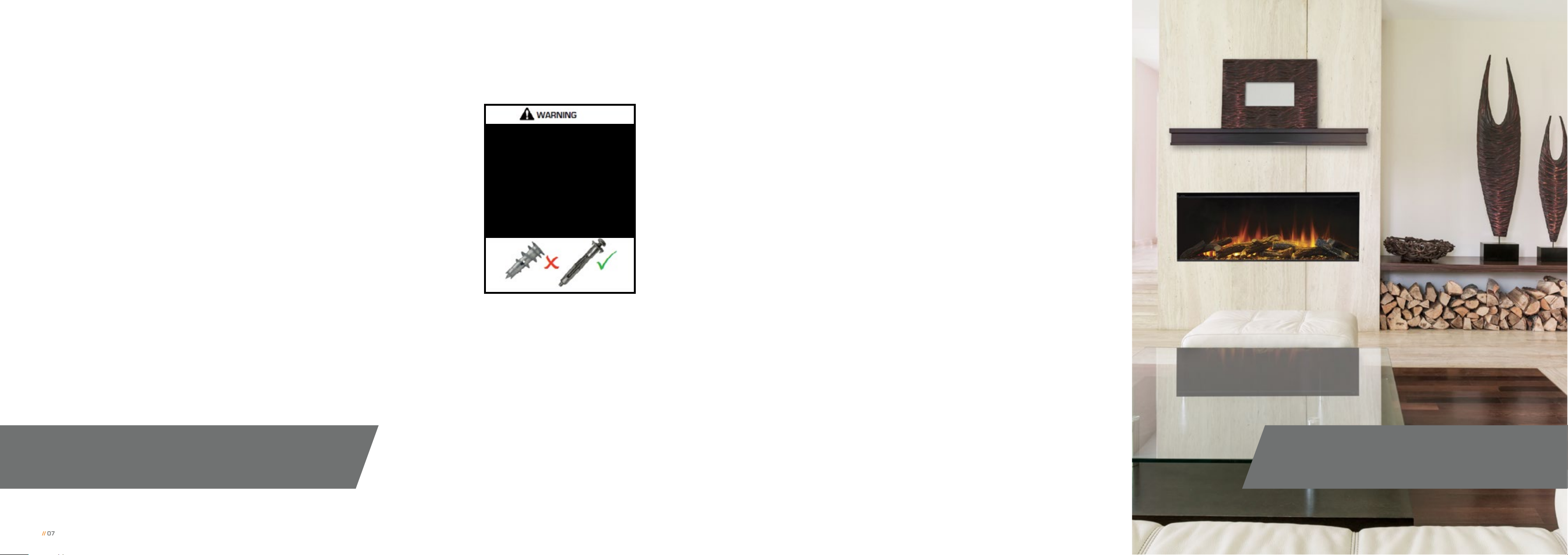
British Fires assumes absolutely no responsibility for injuries and
damages that may occur due to improper installation or handling.
Remove any protective film coatings from the finished/decorative
surfaces of the appliance, if any. After having selected the final position
of the appliance taking into account the integrity of the wall the electric
appliance may be secured to the wall.
To ensure customer safety, be sure to design the installation so that
the strength of both the wall and any wall fixings used are sufficient. Do
not block the ventilation holes of the appliance. The wall onto which the
appliance/stud wall is installed must be flat. Install only on a vertical
surface. Avoid sloped surfaces. Installation onto anything other than a
vertical wall may result in fire, damage or injury.
If the appliance/stud wall is to be mounted on a dry lined wall or a timber
framed construction wall then efforts should be made to fix into two or
more wooden studs, or supporting wooden members of the wall using
the fixing screws provided. If this is not achievable then the wall should
be strengthened using appropriate building materials.
Ensure that the correct wall plugs are used for the type of wall that the
stud work is being connected to.
Ensure the plug or fuse spur is fully accessible.
// WARNING:
Before enclosing the appliance, test the power in situation
in order to ensure the power to the appliance working properly.
The wall where the appliance is to
be installed must be capable of longterm support of the total load of the
appliance. Measures should also be
taken to ensure sufficient strength to
withstand the force of earthquakes,
vibration and other external forces.
Plasterboard alone is not considered
to be a structural material. It is not
recommended to rely on plasterboard
fixings alone to support the weight of
the appliance.
Check regularly for security of wall fixings as
appropriate. Also check security of supply cable and
connections. If the supply cable becomes damaged,
it must be replaced by a service agent or competent
person, such as a qualified electrician.
The stud wall MUST include a header at the dimensions,
highlighted on the following pages. This is to ensure
that the weight of the finished wall is not resting on
top of the appliance.
The power inlet cable can be installed through your
choice of two locations on the top, right hand corner
of the appliance. Each can be accessed through one
removable plate.
This appliance should be positioned on a firm level
surface and in a clean ‘dust free’ environment. If fitted
into an open chimney, the chimney must be blocked
off to reduce the risk of draught and damp through
the fire, which may cause the safety cut out system in
the fan heater to operate.
The base of the opening/stud work must be able to
take the full weight of the appliance.
Any protruding headers MUST be made of a non-combustible
material. See page 10.
To install into a stud wall the mounting bracket must
be removed from the rear of the appliance as shown
in section 8.2.
Once the frame work has been constructed and secured to the wall
and the appliance is in its end position, ensure that there is power
to the appliance before any cladding/plasterboard is installed.
// CAUTION:
Do not keep the appliance connected to the electrical supply at this time.
// 08© 2019 British Fires
Page 6
// 8.1 INSTALLATION – STUDWALL
// 09
Stud wall installation Continued
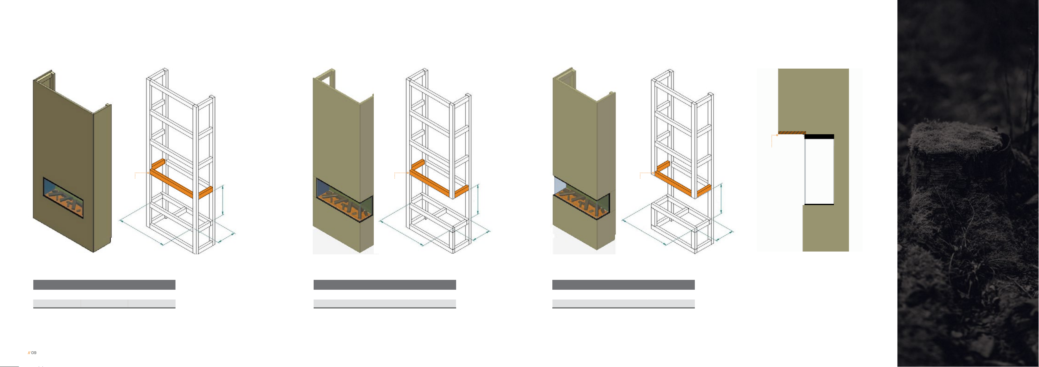
Stud Wall
*Non-combustible
Appliance
Header HeaderHeader
W
H
D
W W
H H
D D
// One-sided (fully-recessed) installation // Two-sided installation // Three-sided installation
Open Dimensions
Height Width Depth
570mm 1180mm 300mm
Open Dimensions
Height Width Depth
570mm 1180mm 300mm
Open Dimensions
Height Width Depth
570mm 1180mm 300mm
*If the stud wall immediately above the
heater protrudes beyond the front of
the appliance then the over-hanging
section of the installation must
be made from a non-combustible
material, such as calcium silicate/
fireboard.
// 10© 2019 British Fires
Page 7
// 8.2 INSTALLATION – FLOATING
// 11
Floating installation
450mm
350mm
350mm
350mm
50mm
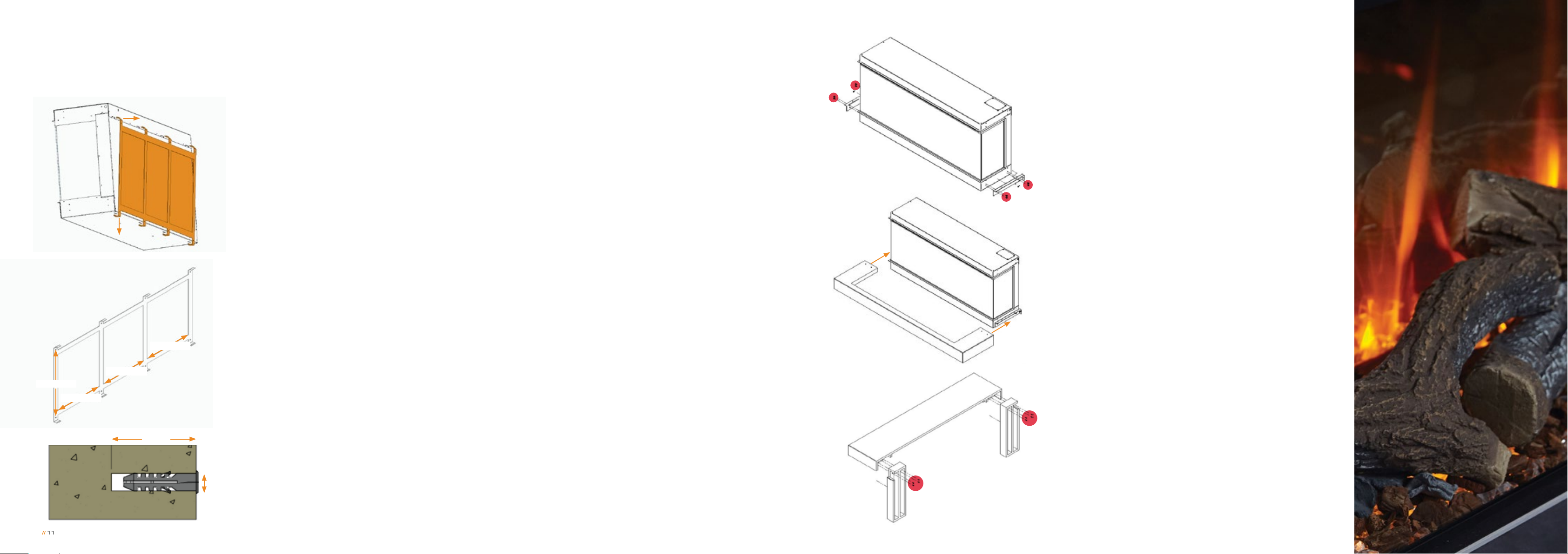
Before Installing the appliance onto the wall with the surround, secure the side trims each side
of the appliance as described in section 9.0 Preparing the Appliance.
The installation should be carried out by two adults to avoid injury or damage. If for any reason
it is considered too heavy, please obtain assistance.
1) Remove the mounting bracket from rear of the
appliance by moving the bracket down and out
from the appliance.
2) Find the optimal place to mount your appliance.
Consider the proper position relative to your room,
placement of furniture and windows.
3) Hold the mounting bracket up to the wall to verify
the correct location and ensure that the mounting
bracket is level. Use a pencil to mark the eight
mounting holes on the wall at the desired mounting
location, using the mounting bracket as a template.
4) Drill a 8mm diameter holes to at least 50mm deep
on the marked points.
NOTE: If installing the mounting bracket to a wall stud, there
is no need to drill the holes in the wood and no need for
the plastic wall anchors. It is recommended to install the
mounting bracket to at least one wooden stud.
5) Tap the 8x wall anchors into the pre--drilled holes
with a hammer until they are flush with the wall.
8) With the appliance on the wall offer the floating
shelf brackets to either sides of the appliance
lining up all 8x holes on the floating bracket with
the 8x holes on the side of the firebox. Then mark
with a pencil through the hole in the end of the
bracket against the wall.
9) Remove the appliance off of the wall.
10) Drill a 8mm hole at least 50mm deep on either
side of the appliance.
11) Tap the two wall anchors into the pre--drilled holes
with a hammer until they are flush with the wall.
12) Install the appliance back onto the wall and screw
the floating shelf brackets on to the sides of
the appliance with the 8x loose firebox screws
provided.
13) Then screw the wall screws through the rear of
the floating shelf brackets and into the wall plugs.
14) Carefully slide the bottom of the surround onto
the floating shelf brackets.
15) Screw the two legs of the surround from the rear
onto the back of the top section of the surround
as shown, left
8mm
6) Secure the mounting bracket to the wall by using
all 8 wall-fixing screws.
7) Carefully, install the appliance back onto the wall
bracket.
// 12© 2019 British Fires
Page 8
// 8.2 INSTALLATION – FLOATING
// 13
Floating installation continued
// 9.0 PREPARING THE APPLIANCE
For a two or three-sided installation
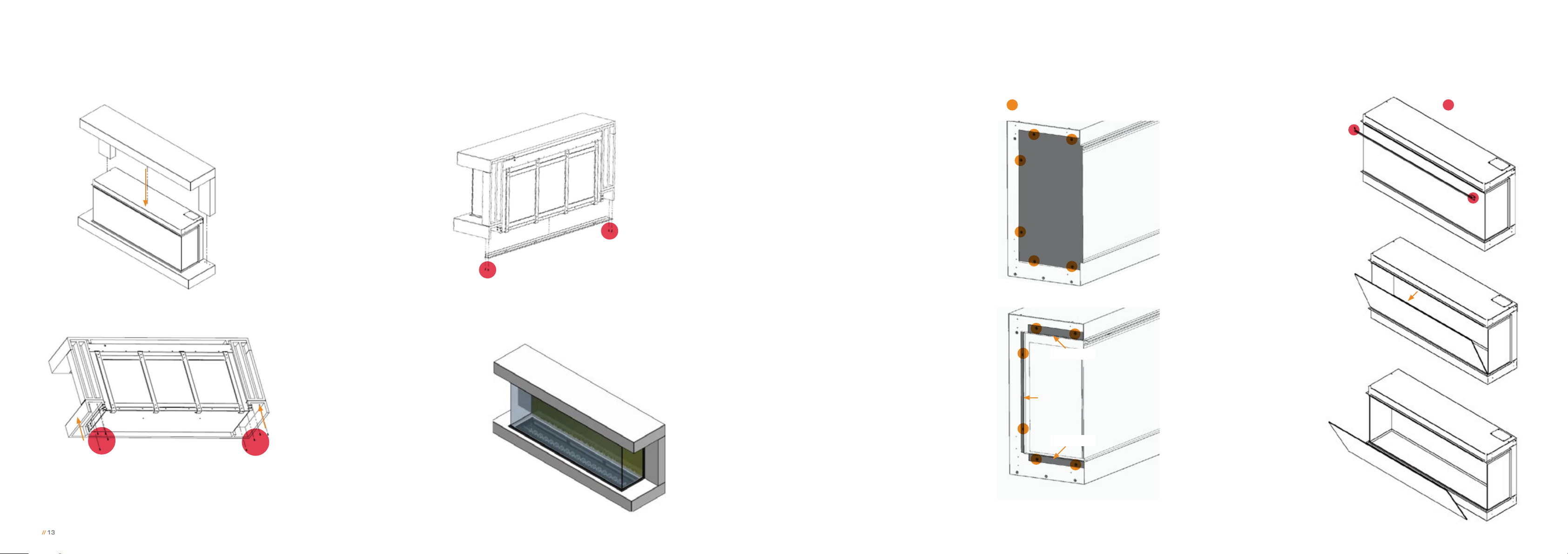
16) Carefully lower the
top section of the surround onto the top of the firebox.
18) Install the bottom panel onto the underside to the
surround with the four surround screws left over.
For a two-sided installation, add
one of the blanking plates and
secure with the six firebox screws
into position. Next add the two
small trims and the large trim to
the side of the appliance. Then
line the holes of the trims with
the corresponding holes of the
firebox and screw into position
with the six countersunk screws,
previously removed.
For a three-sided installation,
secure the small and large trims
on both ends of the appliance in
line with the corresponding holes
of the firebox. Secure into position
with the 12 supplied firebox
screws, six on each side.
Firebox screws
Blanking Plate
Small trim
Large trim
We strongly recommend that two people
are used to remove the glass, both using
protective gloves.
To remove the front glass from
the appliance, use a cross headed
screwdriver to remove the screws
from either end of the top bracket
of the appliance, holding the glass
in place.
Ensure the glass is supported at all times.
Next, gently leaver the top of the
glass towards you, ensuring you
have full support of the glass.
Lift the glass up and out from the
appliance and place the glass on a
soft, flat surface on the floor.
Insert your prefered fuel bed
options as shown in the following
pages in section 10.0 – 10.2.
To re-install the glass, see the
instructions in reverse order.
Crosshead screws
17) Underneath the appliance, with the surround screws,
screw up through the bottom surround and into the
legs of the surround top section and up through the
floating shelf brackets on the appliance the top section.
Small trim
// 14© 2019 British Fires
Page 9
// 10.0 FOREST VIEW FUEL BED LAYOUT
// 15
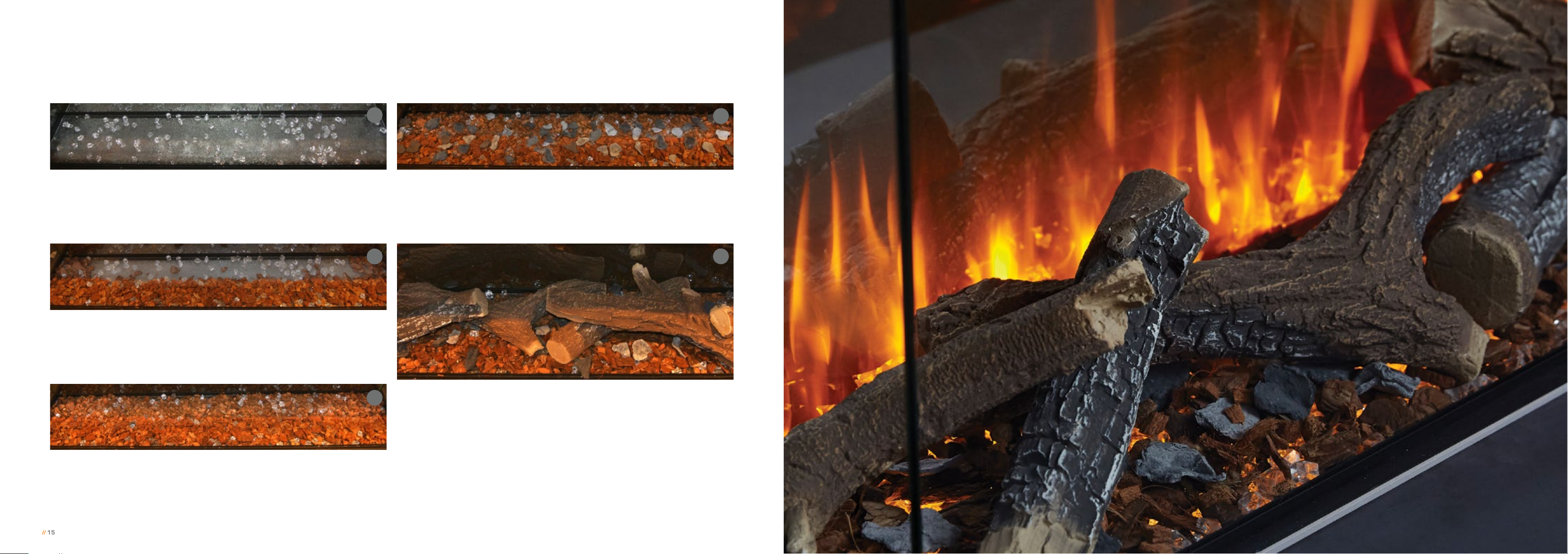
Forest View
1
Taking a small account of the small crystals, scatter randomly over the
frosted base as shown above.
PRO TIP – Use the small crystals to pick up extra light from the fuel bed to give you
the best effect.
2
Use the contents from the Forest terrain bag and place this in the
formation shown above (image 2) towards the front and sides of the
frosted base. There should be a single layer to cover this area of the
frosted bed and the crystals still visible.
4
Use the slate pieces and place these randomly on the bed as shown in
image 4, above.
5
3
Using the contents from the Husk bag, cover the area on the frosted
bed that is still exposed, making sure the crystals are still visible.
Place the logs on top of the base layer created by the crystals, Forest
terrain, Husk and slate pieces. Position them as shown above. The logs
can be placed in any order, for this look the larger logs are in the center
with the remaining logs around them.
IMPORTANT – Place the logs carefully on the fuel bed so you do not make contact with the
rear and side glass. Contact with glass may cause damage.
// 16© 2019 British Fires
Page 10
// 10.1 SLATE VIEW FUEL BED LAYOUT
// 17
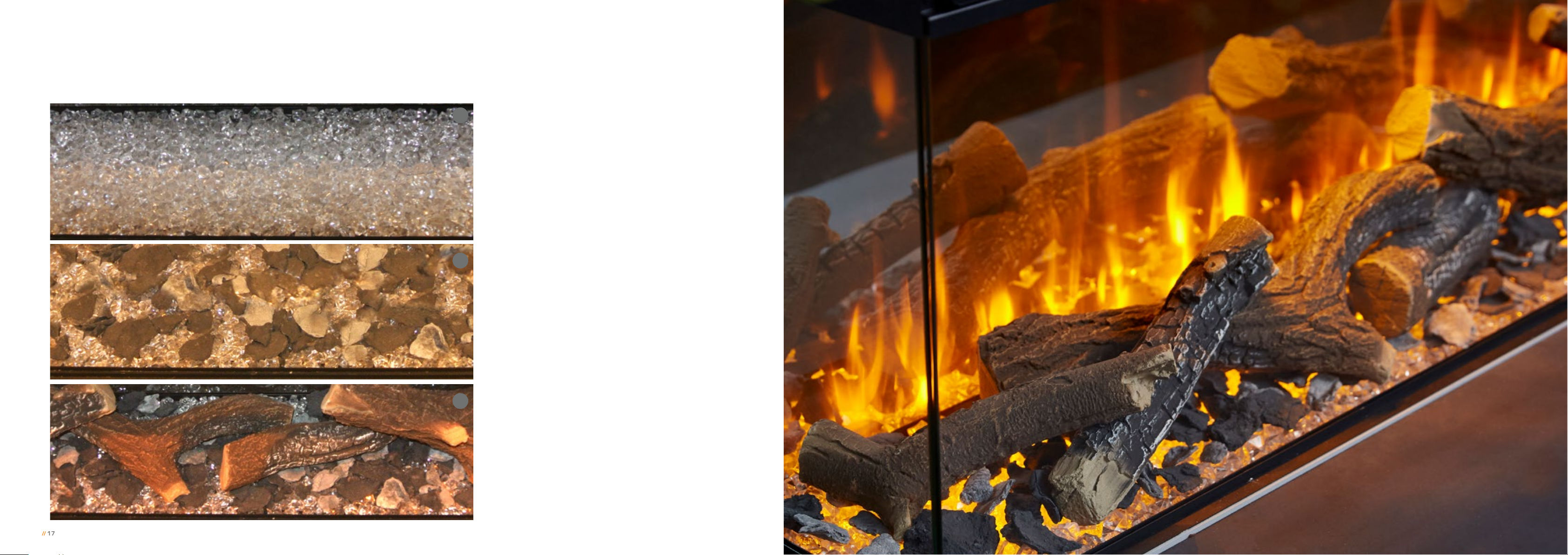
Slate View
Evenly scatter the small crystals over the frosted
1
base as shown in image 1, left. The crystals should
be spread out across the whole base and form a layer
covering the whole area.
Take the two types of the slate effect pieces and
2
spread these evenly throughout, on top of the bed
of crystals.
Place the logs on top of the base layer created by the
3
crystals and slate pieces. Position them as shown in
image 3. The logs can be placed in any order, we have
used the larger ones as centre pieces and placed the
remaining logs around them.
IMPORTANT – Place the logs carefully on the fuel bed ensuring
you do not make contact with the rear or side glass. Coming into
contact with glass may cause damage.
// 18© 2019 British Fires
Page 11
// 10.2 DIAMOND LIGHT VIEW FUEL BED LAYOUT
// 19
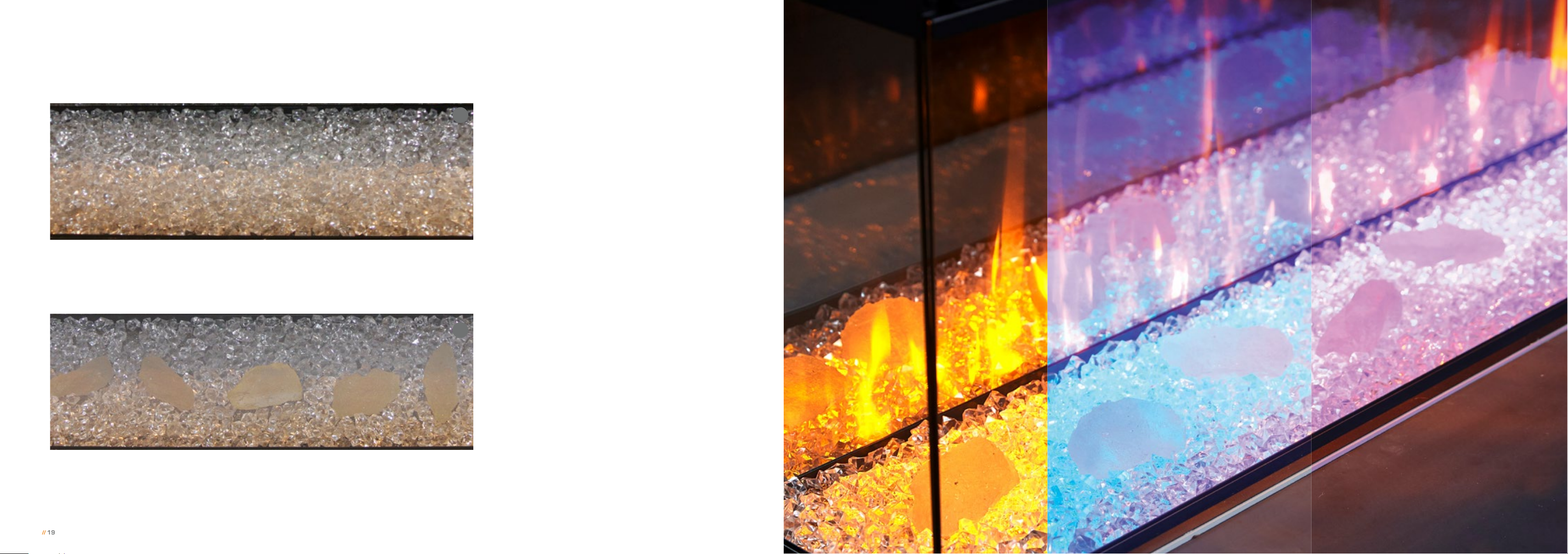
Diamond light View
Evenly scatter the small crystals over the frosted
1
base as shown in image 1, left. The crystals should
be spread out across the whole base and form a layer
covering the whole area.
Three Diamond Light colour settings
Take the larger crystals and place these in position as
2
shown in image 2, left. For the best results, remove
a small amount of the small crystals and place the
larger crystal directly on the frosted base.
// 20© 2019 British Fires
Page 12
// 11.0 PAIRING THE REMOTE CONTROL
// 21
Pairing the remote control
// 12.0 OPERATING THE APPLIANCE
Within 1 minute of turning the power on by the main
ON/OFF switch (located on the front, top right hand
side of the appliance), press and hold and the and
buttons on the remote control for 3 seconds, to
remotely pair to the appliance, the LCD only displays
bL (displayed at the display temperature position) and
flashes 5S, then returns to the current display state.
The remote is then paired to the appliance.
The ON/OFF switch is located on the front, top right hand side of the appliance.
Press the O/I button once to turn the fire on.
REMOTE CONTROL
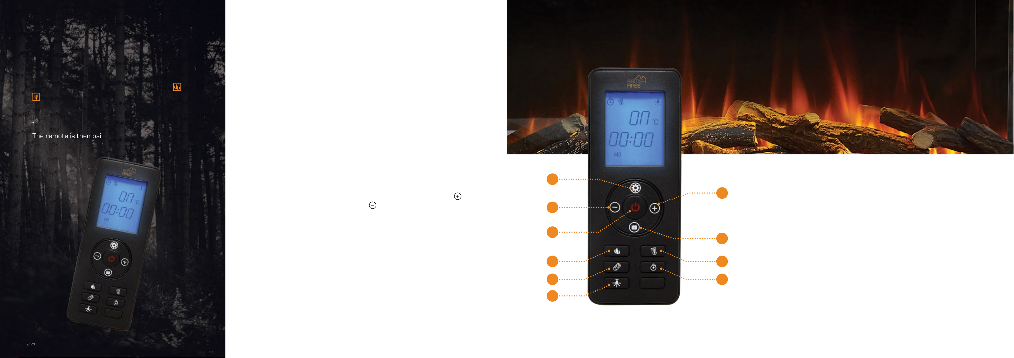
The button distribution of the remote controller is as shown right, and
the current state information of the electric fireplace, such as the flame
effect, fuel bed, setting, temperature and time set, is displayed on the
LCD screen on the remote control.
1) Standby
Turns the appliance ON/OFF
standby, the default settings are:
heater set to 82°F/27°C, the
main flame effect is F1, the Fuel
bed is L1 (no temperature display).
2) Flame Control
Changes the flame effect brightness
F1, F2, F3, F4, F1 (cycle adjustment)
3) Heater
Heater button switches to the
temperature adjustment option
when the weekly timing function
is adjusted. Then use the
and
buttons to select the desired
temperature. The temperature
cannot be adjusted while the daily
timer control is in use. Only the
heating function can be switched.
Temperature Setting range:
Centigrade: 17°C, 18°C, 19°C, 20°C,
21°C, 22°C, 23°C, 24°C, 25°C, 26°C,
27°C, ON, 17°C (Cycle)
Fahrenheit: 62°F, 63°F, 64°F, 65°F, 66°F,
67°F, 68°F, 69°F, 70°F, 71°F, 72°F, 73°F,
74°F, 75°F, 76°F, 77°F, 78°F, 79°F, 80°F,
81°F, 82°F, ON, 62°F (Cycle)
* Press and hold the heater button for
3 seconds can transfer from °C to °F.
7
8
1
2
4
6
9
10
3
5
4) Fuel Bed
Changes the colour of the fuel bed.
L1, L2, L3, L4, L1 (cycle adjustment)
5) Sleep Timer
Adjusts the timer: 1H, 2H, 3H, 4H,
5H, 6H, 7H, 8H, 9H, OF, 1H (cycle)
6) Down Light
Turns the down lighting ON/OFF,
(the down light symbol will be lit
when it is turned on).
7) Time and Week Settings
Press to enter the time and week
timer settings.
8) Lower temperature 1°C
Press this button to lower the
temperature by –1°C, incrementally,
while the heating is turned on.
9) Raise Temperature 1°C
Press this button to raise the
temperature by +1°C, incrementally,
while the heating is turned on.
10) Date Set
To choose from Monday to Sunday
or week timer mode option. Option
mode:1-2-3-4-5-6-7-A-oF.
// 22© 2019 British Fires
Page 13
// 12.0 OPERATING THE APPLIANCE
// 23
Continued
Standby Button:
Turns the appliance ON/OFF
standby, the default settings are:
heater set to 82°F/27°C, the
main flame effect is F1, the Fuel
bed is L1 (no temperature display).
Changing Flame Effect:
In the power-on state, press this
button, the digital screen displays
the flame position and the flame
indicator is bright, and the main
flame position can be adjusted.
The flame brightness settings are:
F1, F2, F3, F4, Set as follows:
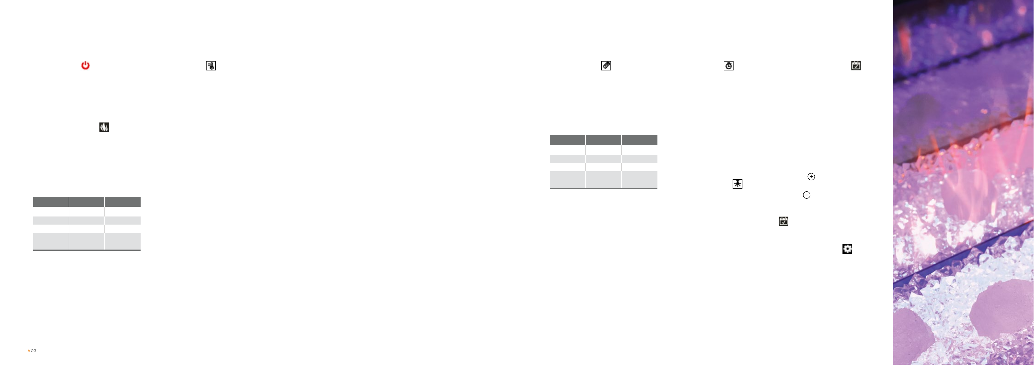
Button Display Flame Effect
1st Press F1 Full
2nd Press F2 Medium
3rd Press F3 Low
4th Press F4
cycle through
settings
Heating Operations:
1) Press the heater button to turn
the heating function on and off and
adjust the temperature setting.
Heater is divided into temperature
settings: 17°C, 18°C, 19°C, 20°C,
21°C,22°C, 23°C, 24°C, 25°C,
26°C, 27°C, ON, 17°C. (Circular
operation control)
2) Press and hold the heater
button for 3 seconds to convert
the temperature unit from °C to °F.
The temperature display window
will flash. After the temperature is
set, the display unit will flash 5
times, then automatically saves
the settings and exits the setting
state. After the display unit is
turned on, if there is no operation
within 10 seconds, the setting
status is also exited.
3) Fan delay function: After the
appliance is turned off, the fan will
continue running for 15 seconds
then stop.
Open Window Detection function:
When the appliance is heating, the
ambient temperature suddenly
drops ≥–5°C within 10 minutes,
and the environment cannot be
warmed up within 30 minutes.
The appliance will automatically
display “OP”. The heating function
will be automatically turned off,
and when the “OP” is displayed, it
can be turned off and then
restarted by turning off and on the
appliance to clear the fault code.
4) This appliance has a non-self-
resetting overheat protection
device (thermal cut-out) which will
activate if the air inlets or outlets
are obstructed. For safety reasons
the fire will NOT switch on again
automatically, the following
procedure must be carried out
before the fire can be operated.
NOTE: The flame-effect will remain
operational if the cut-out is activated, only
the fan heater is prevented from working.
Switch OFF the appliance at the
wall socket or outlet. Leave the fire
OFF for a period of no less than 10
minutes, ensuring all obstructions
are removed. Switch the appliance
ON at the wall. Ensure the
appliance is turned ON at the
control switches. If the fire fails to
operate correctly, repeat the
above procedure.
Fuel Bed Options:
Once powered, press the “Fuel
Bed” button and the LCD screen
on the remote will display the fuel
bed icon. Now, the fuel bed colour
can be adjusted. The different
settings are: L1, L2, L3, L4; Fuel
bed light. Set as follows:
Button Display Flame Effect
1st Press L1 Orange
2nd Press L2 Blue
3rd Press L3 Orange + Blue
4th Press L4
Cycle through
settings
Setting Sleep Timer:
In the timed display, press the
“Sleep Timer” button to adjust the
time, plus one hour for each press.
(You can’t enter the weekly timing
selection, you can only set the
current automatic shutdown time.
This function is available when the
weekly timing function is turned on.
Will not operate). Timing range:
1H, 2H, 3H, 4H, 5H, 6H, 7H, 8H,
9H, OF, 1H (cycle adjustment).
Control Down Lighting:
Turns the down lighting lights on
and off.
Setting Clock and Timer:
Use the date button to choose
from Monday to Sunday or week
timer mode option. Option mode:
1-2-3-4-5-6-7-A-oF.
Clock setting:
1) At standby state (after the unit
is plugged in and before pressing
“main power”), press and hold the
Setting button on the remote for 3
seconds, the digital display will the
flash “00:00”.
2) Press on the remote control
to set the hour, press the remote
control to set the minutes.
3) Press “Setting” to enter the
setting of the week timer. Press
to select Sunday to Saturday,
The date symbol will be light up
after the day is selected. When
finished, press the button to
exit setting.
4) The current clock must be set
after the initial power-on or poweroff, otherwise the clock will remain
“00:00” status and you won’t be
able to set the week timer function.
// 24© 2019 British Fires
Page 14
// 12.0 OPERATING THE APPLIANCE
// 25
Continued
// 13.0 SAFETY CUT-OUT SYSTEM
// 14.0 CLEANING AND MAINTENANCE
Heat settings:
Use remote control’s Heater button
to select the temperature. The
system default parameters are:
82°F/27°C. Press & buttons
to select the temperature when
the heating is turned on.
Temperature range: 17°C, 18°C,
19°C, 20°C, 21°C, 22°C, 23°C,
24°C, 25°C, 26°C, 27°C, ON,
17°C. (Cycle)
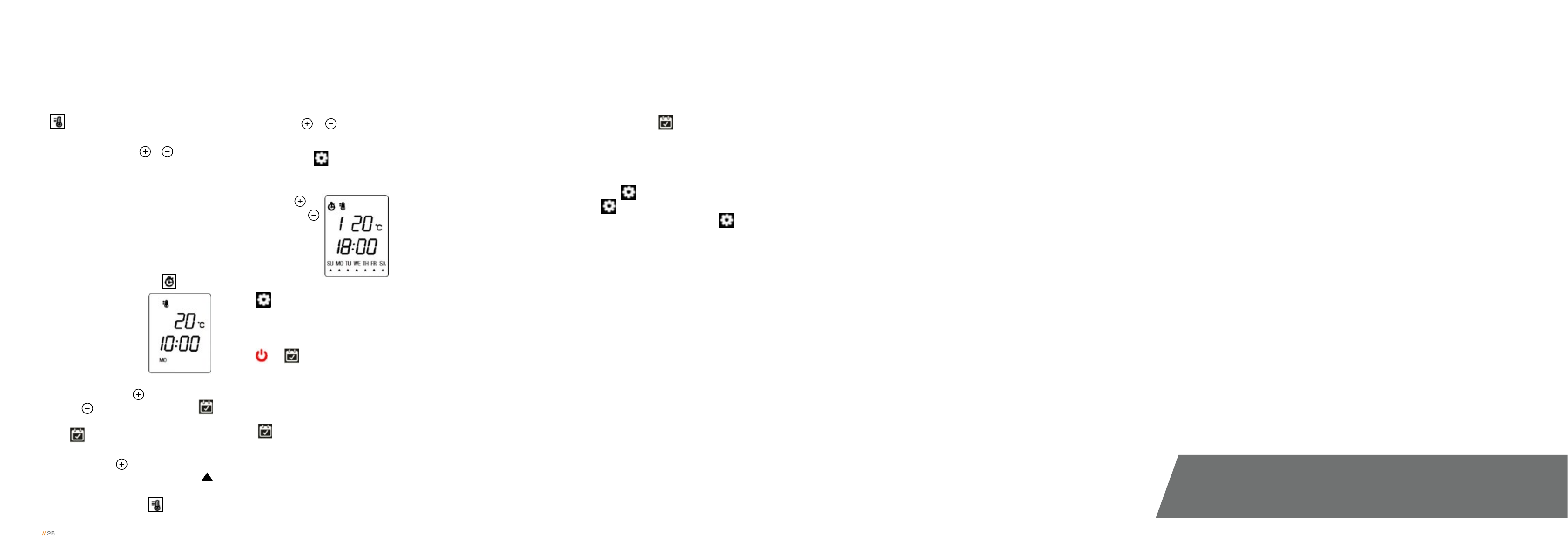
Timing switch ON/OFF preset:
1) While in the standby state,
press the sleep timer
button
on the remote for
three seconds to
pre set timing
switch on/off the
week timer. Enter
mode 1, while the
display is “1 ON”, the clock will be
“01:00”, press
to set hour,
press to set minute, press
to set the week, every press on
the will show SU, MO, TU, WE,
TH, FR, SA and flash in turn, you
can use the key to select or
de-select the desired date. The
indicates all of the selected days.
Press the “Heater”
button to
enter the temperature setting,
then press the
& button to
set temperature.
2) Press “Setting”
again to set
the timer switch off, the display is
1 OFF, the clock is displayed as
“02:00”, press
set hour, press
to
to set minute, the
date of the timer off
is the same as the
timer on, you can’t
change this manually. After setting,
press
to enter the setting of
mode 2, which operates the same
as mode 1. You can set mode 1 to
mode 7 with the above method.
Press
or
on the remote for
3 seconds to save setting and exit
week timer setting.
3) After the preset timing ON/
OFF switch, you can use clock/
timer
button to select the
desired timing mode 1-2-3-4-5-6-
7- auto option, after the option
shows five seconds without any
operation, it will save the selected
option and enter the current
setting of the option, the timer
logo of the display lighten and will
automatically run the preset
switch setting program. You can
individually select each setting of
modes 1–7 for automatic ON/OFF
switching, or you can preset the
desired settings, and then select
“auto mode” for multiple preset
series executions.
4) If you want to set the ON/OFF
switch and temperature setting
for different periods of the week,
then set the switching time and
temperature of each day from
Sunday to Monday in mode 1–7.
After setting, use “auto mode” to
run timing switch and then
system will run the week timer of
1–7 modes. You can also set 1–7
modes within 1 day, use “auto
mode” to run timing switch ON/
OFF within one day. Be aware
that when you use “auto mode”,
you need to make sure the
settings of times does not
overlap each other, otherwise
the timer will not operate.
5) After entering the week timer
setting, press the
button for 3
seconds to exit week timer mode,
then the timer symbol will be
extinguished. You can check the
1–7 timer settings by pressing the
“Setting”
press
button. Example:
to display (1 ON “01:00”
temperature 27°C), press
again to display (1 OFF “02:00”
temperature 27°C). Press the
“Setting” button again to display
(2 On “03:00” temperature
26°C) then press the Setting
button to display (7 OFF “13:00”
temperature 27°C). The wireless
remote control and the
appliance must be kept within 4
meters to prevent the remote
control and the appliance from
failing due to the distance
exceeding the effective remote
control range when working at
the weekly timing. After the
weekly time is turned on, the
remote controller automatically
controls the appliance at the set
appointment time.
Cleaning:
This appliance has a non-self-
resetting overheat protection
device (thermal cut-out) which
will activate if the air inlets or
outlets are obstructed. For safety
reasons the fire will NOT switch
on again automatically.
The following procedure must be
carried out before the fire can be
operated again:
1) Switch OFF the appliance at the
wall socket or outlet. Leave the
fire OFF for a period of no less
than 10 minutes, ensuring all
obstructions are removed.
If the fire fails to operate correctly,
repeat steps one and two. If an
attempt to switch on the appliance
is made before the safety cutout has reset, the appliance may
cut-out for a further period of time.
If the sequence has been followed
correctly and the appliance still
fails to function, check the fuse
in the wall outlet. If this is not
the cause, call an electrician or
maintenance engineer.
NOTE: The flame-effect will remain
operational if the cut-out is activated and
only the fan heater is prevented from
working.
For general cleaning use a soft
clean duster – never use harsh
abrasive or cleaners. The glass
panels should be cleaned carefully
with a soft cloth. To clean the
inside of the glass please refer to
section 9.0.
Except for periodic cleaning of
dust, there are no specific
requirements for care, other than
regular cleaning of the general
appliance. A wipe with a dry cloth
is normally sufficient. DO NOT
use abrasive cleaners as they
can damage the finish. Make sure
the heater outlet and inlet grille
2) Switch the appliance to ON at
the wall.
3) Ensure the appliance is turned
ON at the ON/OFF switches.
NOTE: During the cut-out test the fire will
automatically display ‘88’.
(located on the top, front, centre
of the appliance) is kept clear of
dust, pet hair and other airborne
household matter. These should be
vacuum cleaned periodically using
a brush attachment. The LED light
Handset Battery Replacement
Battery Requirements:
Two (2) AAA 1.5V
1) Remove the battery cover and
the used batteries from the
back of the remote control.
2) Insert the two replacement
batteries the correct way into
the battery holder — making sure
the batteries are firmly seated.
3) Then insert the battery cover
back into position.
4) You will then need to pair the
remote to the appliance. Please
refer to section 11.0 Pairing
The Remote Control.
If in doubt consult a qualified electrician.
Refer to Section 3.0 Appliance Data for
fuse specification. Excluding fuses, use
only genuine manufacturers spare parts
available from your supplier.
strips are designed and tested to
last 20,000 hours.
// CAUTION:
Always disconnect the appliance from the mains supply outlet
socket before undertaking any cleaning or maintenance!
// 26© 2019 British Fires
Page 15
// 15.0 TROUBLESHOOTING GUIDE // 16.0 SERVICING
// 27
There are no internal user serviceable parts.
My Wall Inset Electric Fire... Remedy
is not switching on Ensure mains switch is on. Replace the fuse in the plug.
is not emitting any heat The fire is fitted with an energy saving thermostat. If the temperature in the room is higher than the
temperature selected on the fire, then the thermostat will stop the heater from turning on. For example,
if the room temperature is 22°C or above and the fires heater is set at 22°C, then the heater will not be
required until the room temperature drops below 22°C. If this is the case select a higher temperature
setting than the room’s temperature and the heater will begin to operate. The safety cut-out may have
been operated. Switch the appliance off, leave for 10 minutes then switch back on.
shuts off after a period of time Check that the temperature is not set onto the lower settings. If the room is warm enough the thermostat
will stop the fire switching the heat on.
Check that the chimney/flue is blocked off.
Check that the window detection sensor has not activated.
Display panel When the display panel displays a red LED, which lights up the EE icon. When the thermostat fails, the
display panel displays a blue LED, which lights up the 88 icon. When the window alarm occurs, the display
panel displays orange and lights up the OP icon.
This appliance is supplied with a
BS1363 3 pin plug fitted with
a 13 Amp fuse. Should the fuse
require replacing, it must be
replaced with a fuse rated at 13
Amp and approved to BS1362. In
the event of the mains plug being
removed/replaced for any reason,
please note :
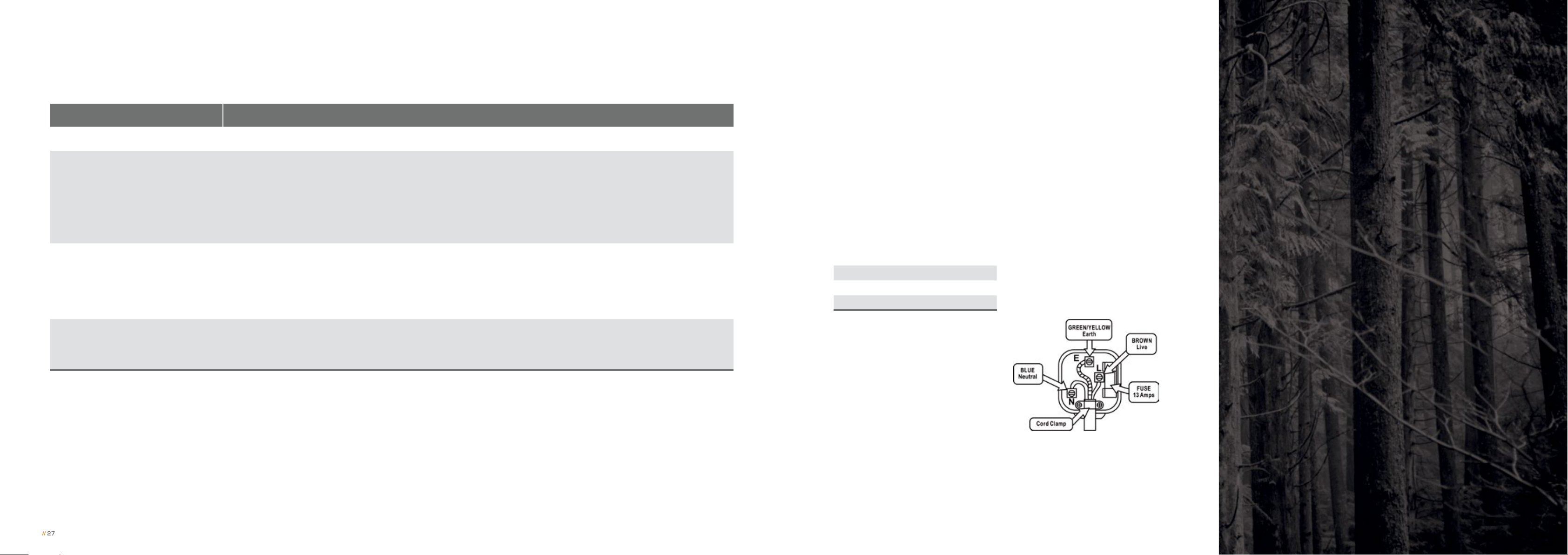
IMPORTANT: The wires in the mains
lead are coloured in accordance with the
following code:
Blue Neutral
Brown Live
Green/Yellow Earth
As the colours of the wires in the
mains lead of this appliance may
not correspond with the colour
markings identifying the terminals
in your plug, proceed as follows.
The blue wire must be connected
to the terminal marked with an N
or coloured black. The brown wire
must be connected to the terminal
marked with an L or coloured red.
The green/yellow wire must be
connected to the earth terminal
which is marked with an E or with
the earth symbol.
// WARNING:
Never connect live or neutral wires to
the earth terminal of the plug.
NOTE: If a moulded plug is fitted and
has to be removed take great care
in disposing of the plug and severed
cable, it must be destroyed to prevent
engaging into a socket. Refer to
Section 3.0, Appliance Data for fuse
specification. Excluding fuses, use only
genuine manufacturers spare parts
available from your supplier.
// 28© 2019 British Fires
Page 16
// 17.0 APPLIANCE DIMENSIONS // 18.0 GUARANTEE, TERMS & CONDITIONS
// 29
AUTOMATIC 1-YEAR GUARANTEE
A
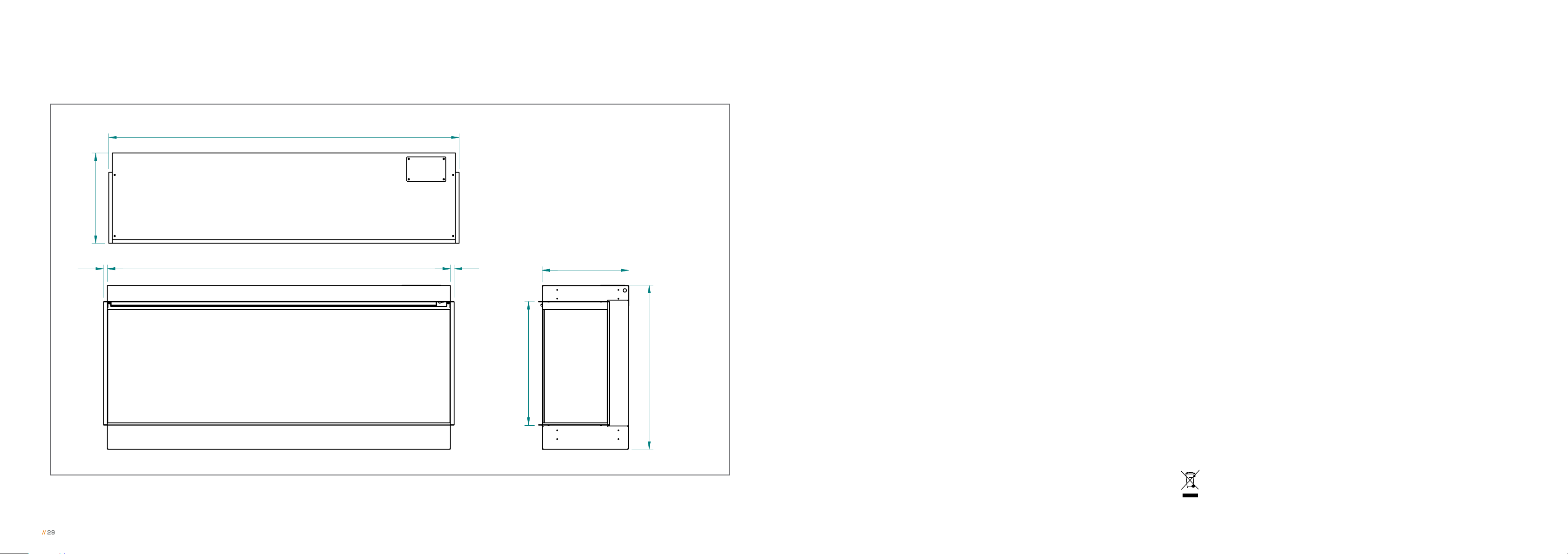
// APPLIANCE DIMENSIONS:
A: 1200 mm
B: 310 mm
C: 1178 mm
B
E
C D
D: 12.5 mm
E: 12.5 mm
F: 297.4 mm
G: 424 mm
H: 563 mm
F
We offer a standard one-year guarantee on every electric appliance.
FREE 3-YEAR GUARANTEE WITH REGISTRATION
At British Fires we pride ourselves on quality and performance, so much
so that each of our appliances is eligible for a three-year guarantee
when purchased from an authorised dealer. To cover your appliance
for a further two years, free registration is required on our website
www.britishfires.com/guarantee. Full warranty terms and conditions
are available to view at www.britishfires.com.
During the guarantee period any appliance or component which is
proved to be faulty or defective in manufacture, will be repaired or
replaced free of material and labour charges, providing that we have
authorised or carried out the repair or replacement.
We will not accept or reimburse the costs of any third-party who
undertakes any work carried on the appliance or fits parts, unless we
have approved such work in advance of it being carried out.
The guarantee period will not be extended even if we repair or replace
any appliance or part.
Making a claim:
TERMS & CONDITIONS
If you wish to make a claim under our guarantee and all the terms and
conditions for your appliance have been met then please submit the
All appliances must be installed in a correctly ventilated space in
accordance with the manufacturer’s installation instructions and the
following information for the attention of the Service Department to the
address below.
rules in force. This brochure is for guidance only and is not intended
G
H
to replace the installation manual, which provides more detailed
information. All of our fires carry CE Approval. April 2019. British Fires™
1) For any claim to be made within three years from date of purchase you
will be required to provide and supply your original proof of purchase.
2) All appliances must have been installed and operated in accordance
with the manufacturer’s instructions.
3) Purchase(s) must be made through an authorised stockist/retailer.
Please note all consumable items such as any ceramics including; coals, pebbles,
logs, bark, crystals, rear panels are not covered by the 3-year guarantee.
Alternatively, you can email or fax. British Fires, Service Department,
Reid Street, Christchurch, Dorset, BH23 2BT.
Email: Guarantee@britishfires.co.uk Fax: 01202 588639.
Details required:
1) Name, full address including postal code and contact telephone number.
2) A copy of your proof of purchase (e.g. receipt or bank statement).
Please note that this does not affect your statutory rights.
Waste electrical appliances should not be disposed of with household waste. Please recycle where
facilities exist. Check with your local authority or retailer for recycling advice.
As our policy is one of continuous improvement and development, we therefore, hope that you will understand
we must retain the right to amend details and/or specifications without prior notice.
// 30© 2019 British Fires
Page 17

// NOTES
// 31
// 32© 2019 British Fires
Page 18

// NOTES
// 33
// 34© 2019 British Fires
Page 19

// 35
This appliance is only suitable for well insulated spaces or occasional use. Please
note: Except where otherwise stated, all rights, including copyright in the text,
images and layout of this booklet is owned by British Fires. You are not permitted
to copy or adapt any of the content without the prior written permission of
British Fires. © 2019 British Fires
Models covered by
these instructions:
New Forest Electric Fire
(
EF40-48A
)
Patent applied for:
GB 1820239.0
All instructions must
be handed to the user
for safekeeping.
Revision B – 08/19
British Fires
Christchurch, Dorset
BH23 2BT
Tel: 0808 169 9911
www.britishfires.com
Email: sales@britishfires.com
 Loading...