

Page 1
PLC Device Utility User Guide
Introduction
The PLC Device Utility is to create a private PLC network or to assign devices into the network. For PLC
devices which have hardware group or encryption button, creating a private network or assigning devices
can be easy done by this button and this utility software is NOT needed. Please see user manual for
group button operation. This utility software is unavoidable for creating PLC network combining this PLC
device with older version of HomePlug AV devices which has no group or encryption button.
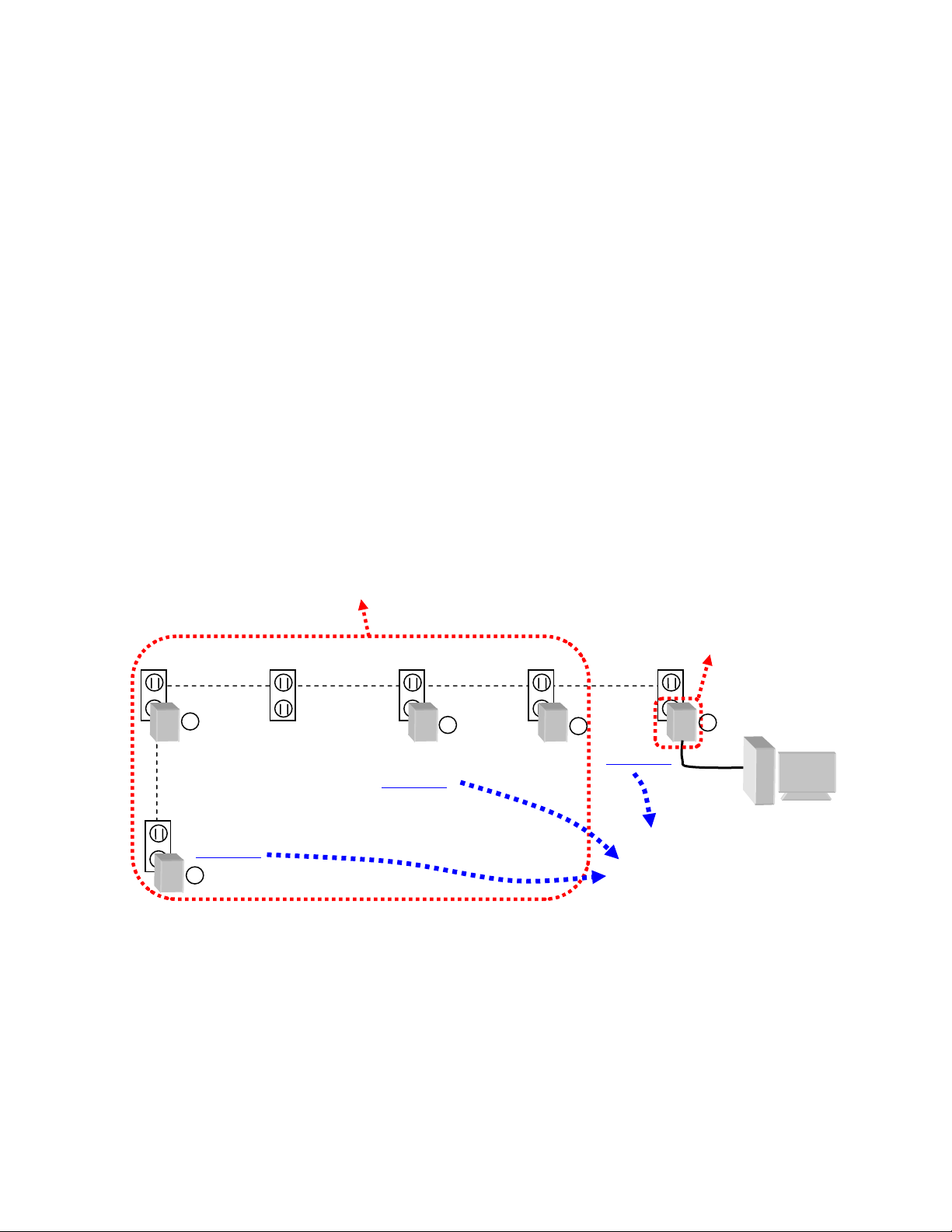
Powerline devices can communicate with each other only if they have same Network Name (for ex, device
1, 3, and 5 in Figure 1 has same Network Name), thus belongs to same network group. Devices with
different Network Name can not communicate. A Network Name of HomePlugAV is public to all new
HomePlug AV compliant devices worldwide. Thus data sent over it is accessible to families using a new
HomePlug AV compliant device.
To ensure privacy of your data transmission, use this utility to create a private PLC network by assigning a
private Network Name to the PLC devices. A device password, know as DAK printed on the back of
devices, is needed in order to change its Network Name or add it into a network group.
Remote
devices
Local Device
(Direct attached
to PC)
PC with
4
Network Name:
HomePlugAV
Network
Name:
MyPLCnet
5
Network
Name:
MyPLCnet
3
Network Name:
HomePlugAV
2
Network
Name:
MyPLCnet
1
Ethernet
Communicable
devices 1, 3, 5 have
same Network Name
PLC Device
Utility
,
Figure 1: private PLC network, device 1, 3, 5 has same Network Name, all non HomePlugAV
Page 1
Page 2
Utility Install
Please verify no other PLC Encryption Management Utilities are installed prior to i nstalling this utility. Other
utilities should be uninstalled before installing this utility. To install, click “Installer.bat”, the installation
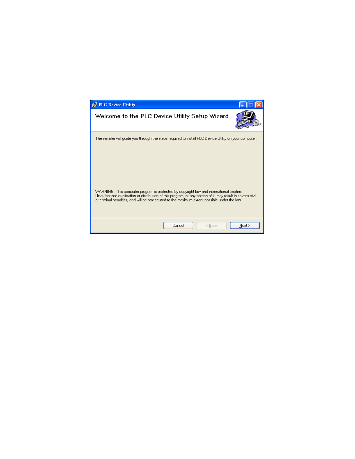
automatically starts. After asking for install WinPcap, a window similar to the one sho wn in Figure 2 will be
launched. Click the Next buttons to continue and finish installation procedure.
U S E R G U I D E
Figure 2: InstallShield Screen
Page 2
Page 3
Running PLC Device Utility
In order to start the utility, double-click the utility icon on your desktop. There are four tab selectable pages:
Main, Privacy, Diagnostics, and About.
Main page
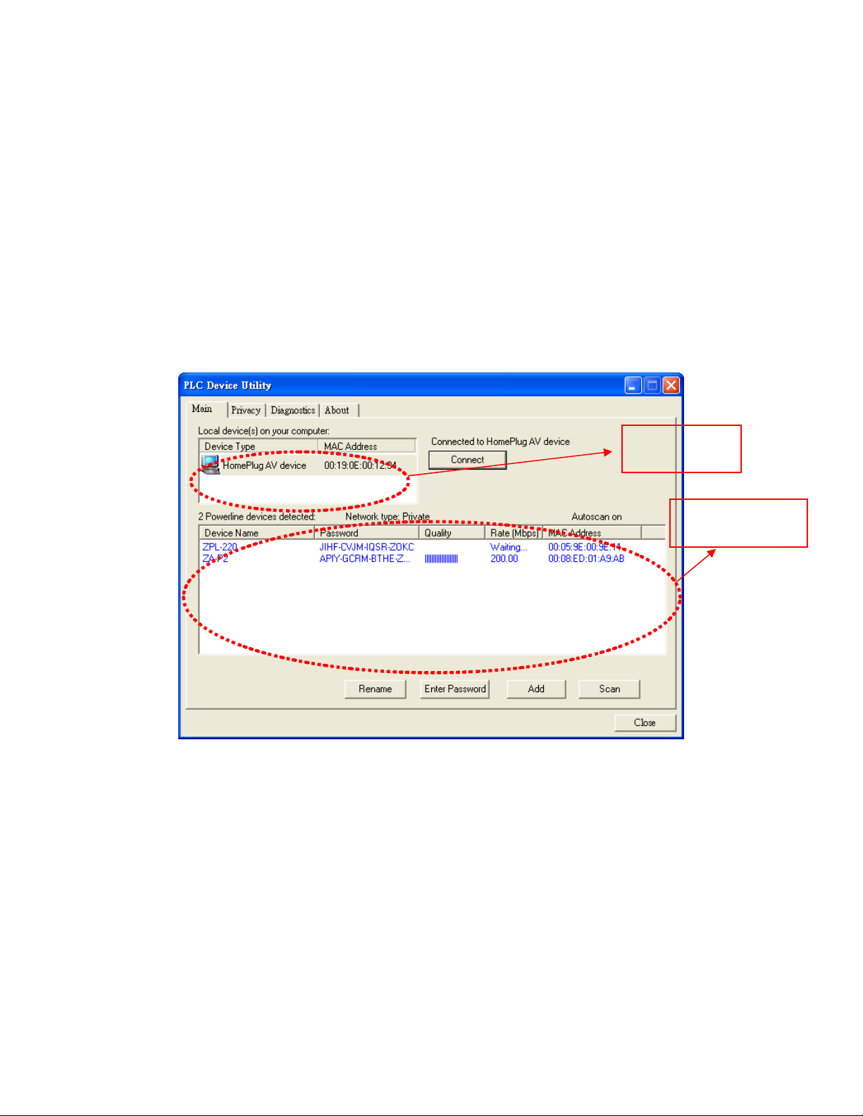
In Figure 3, the Main page shows status of all devices in the current PLC network. It includes two
subwindows.
The top subwindow of the page is called the Local Device Subwindow. It shows a Powerline device of
HomePlug AV device type connected locally to the PC where this utility runs. The MAC address of that
device is shown. The bottom subwindow, called Remote Device Subwindow, shows all remote Powerline
devices communicable with the device at the top subwindow.
Local Device
Subwindow
Remote Device
Subwindow
Figure 3: Main Page with one local and one remote PLC device
.
Local Device Subwindow
It shows all local PLC devices attached via the NICs (Network Interface Cards) of the PC running this
software. In most cases, only one device will be seen in this subwindow. In situations where there are
multiple local PLC devices being connected via extra USB network card or Ethernet adapter, multiple
device will be seen. In this case, please select one as active local PLC device by clicking on it and then
click the Connect button located at its right hand side. For example, since only one local PLC device is
attaching the PC in Figure 1, the main page shown in Figure 3 describes this case.
The area above Connect button indicates that your PC’s connectivity status and the type of local device,
such as “Connected to HomePlug AV Device”. If no local PLC device is discovered, it shows ‘HomePlug
Adapter NOT DETECTED’. This utility supports only PLC devices running HomePlug AV protocols,
Page 3
Page 4

although there are other unpopular PLC communication protocols in the world.
Remote Device Subwindow
It displays all the remote PLC devices accessible to the active device in Local Device subwindow. In
Figure 1, four devices 2, 3, 4, and 5 are remote which can talk to the PC only via power-wire, but only two
accessible devices: 3 and 5 which has same Network Name as local device. The total number of
accessible remote devices is shown at its top-left corner, such as “2 Powerline device detected” shown in
Figure 3.
The Network type (showing Public or Private) shows the network type of the local device. The scanning
status option is displayed at top-right corner of this subwindow if auto-scan function is enabled.
In this subwindow, each powered PLC device accessible to local device will popup a status entry indicating:
device name
in this subwindow.
Device Name
This shows the default device name, which is user changeable by Rename button or by direct clicking on
the name to edit in-place.
Password
First time use of this software shows no devices authenticated and Password are blank for all accessible
remote PLC devices. When changing the Network Name of remote PLC devices or making inaccessible
PLC devices accessible to the local PLC device, password authentication is required. The password, also
called DAK, is printed at back of each purchased PLC device.
Quality
It shows how good the remote device’s communication quality with the local device. Longer symbol shows
better quality.
Rate (Mbps)
It shows the current PHY rate of the communication between remote Powerline device and the local
Powerline device. Best case, the PHY rate could reach 200Mb/s.
MAC Address
It shows the MAC address of the remote PLC devices.
, password, Quality, Rate, and MAC address. If no PLC device detected, no entry is displayed
Scan button
This is used to perform an immediate search of all remote devices accessible to the active local PLC
device. By default, the utility automatically scans every few seconds and updates the status.
Rename button
A typical screen after renaming the remote device to “David's bedroom” and the device password entered
might appear as in Figure 4.
Page 4
Page 5
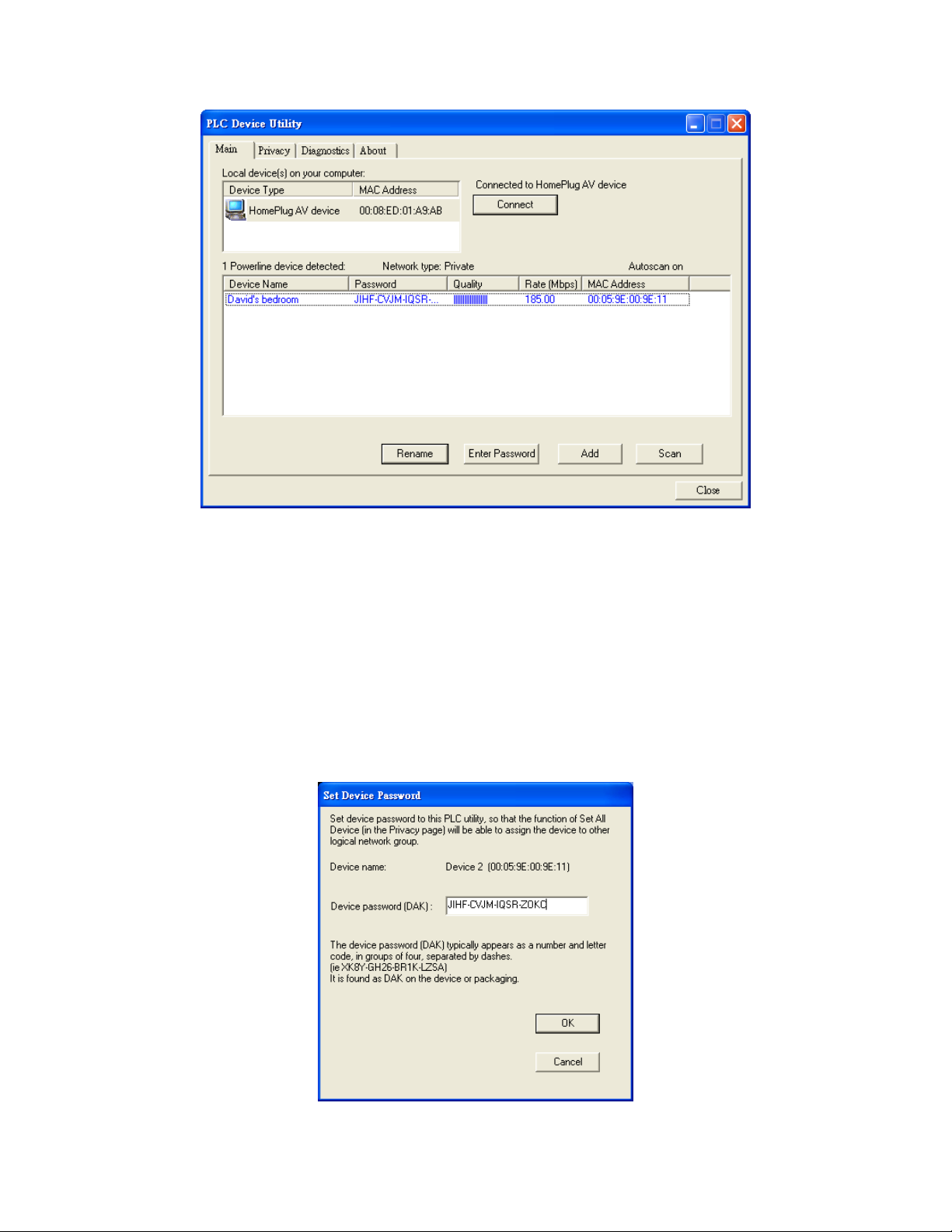
Figure 4: Device Name and Password in Main page
Enter Password button
Before changing a remote device’s Network Name, the device needs be authenticated by entering its
password into this PLC utility software database. First time use of this software shows no devices
authenticated and Password are all blank.
To enter the Password of a device, first click an entry in Remote Device Subwindo w to select the device.
Then, click on the Enter Password button. A dialog box will appear as shown in Figure 5. Type in the
password with dash sign “-“ connecting each for characters and click the OK button. The password, also
called DAK, is printed at back of each purchased PLC device.
Figure 5: Set Device Password
Page 5
Page 6
Join a device to Local PLC device’s network
Use Add button in the Main page to change the Network Name of remote devices to that of local PLC
device and become a communicable member of local PLC device.
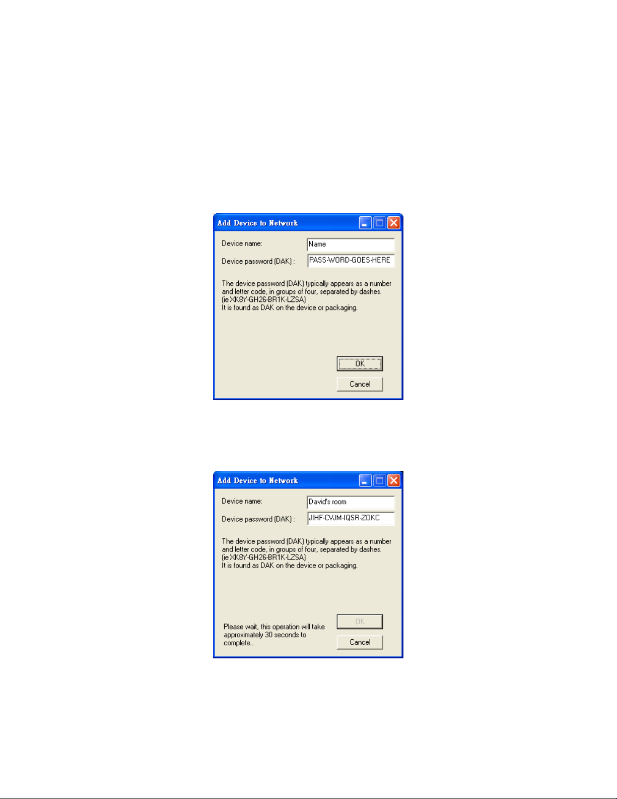
A dialog box as in Figure 6 appears to allow users enter the device password and set its device name.
The password is the DAK printed on the bottom of a PLC device.
Note: keep the device plugged and powered on the electric outlet while computer is adding this device.
Users may find it convenient to write down the DAK in advance to a paper.
Figure 6: Add Remote Device
After typing a device name and hitting OK, it will show the following message:
It takes several minutes to scan whole network and change device’s Network Name. If successful, the
dialog box will show “completing…” It automatically finishes when the dialog box disappears. Check
Remote Device Subwindow for new list of accessible remote devices.
Page 6
Page 7
Create a private PLC network group
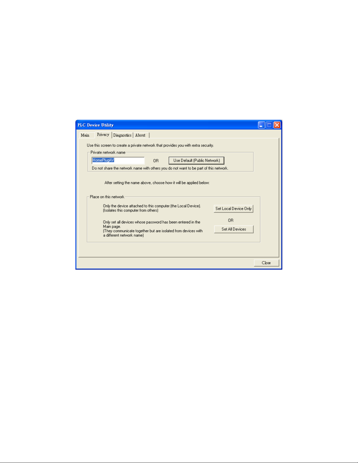
See Figure 7, the Privacy page enables users to change the Network Name of the local or remote PLC
devices. Network Names of inaccessible or accessible remote devices whose password have been
entered into this software’s database will be changed.
All HomePlugAV PLC devices are shipped using a default Network Name of HomePlugAV and are
publically accessible by other PLC devices. To make your PLC device private to other PLC devices, or
back to public Network Name, please enter a private Network Nam e and push Set Local Device Only or
Set All Devices button.
Figure 7: Privacy Page
Set Local Device Only button only change the Network Name of the local PLC device attached to the PC
running this software. After pressing the button, Remote devices differing with entered Network Name
disappear and remote devices matching new Network Name appear in Remote Device Subwindow.
In one push, Set All Devices button will change both the Network Name of local device and Network
Name of all pre-authenticated remote devices. It doesn’t matter whether the remote PLC device was
accessible or inaccessible to the local device before clicking this button. To authenticate a remote device
by entering its passwords, please see other sections of this user guide. A dialog window will appear to
report the success of this operation.
Page 7
Page 8
Manage Authenticated Device in the Utility Database
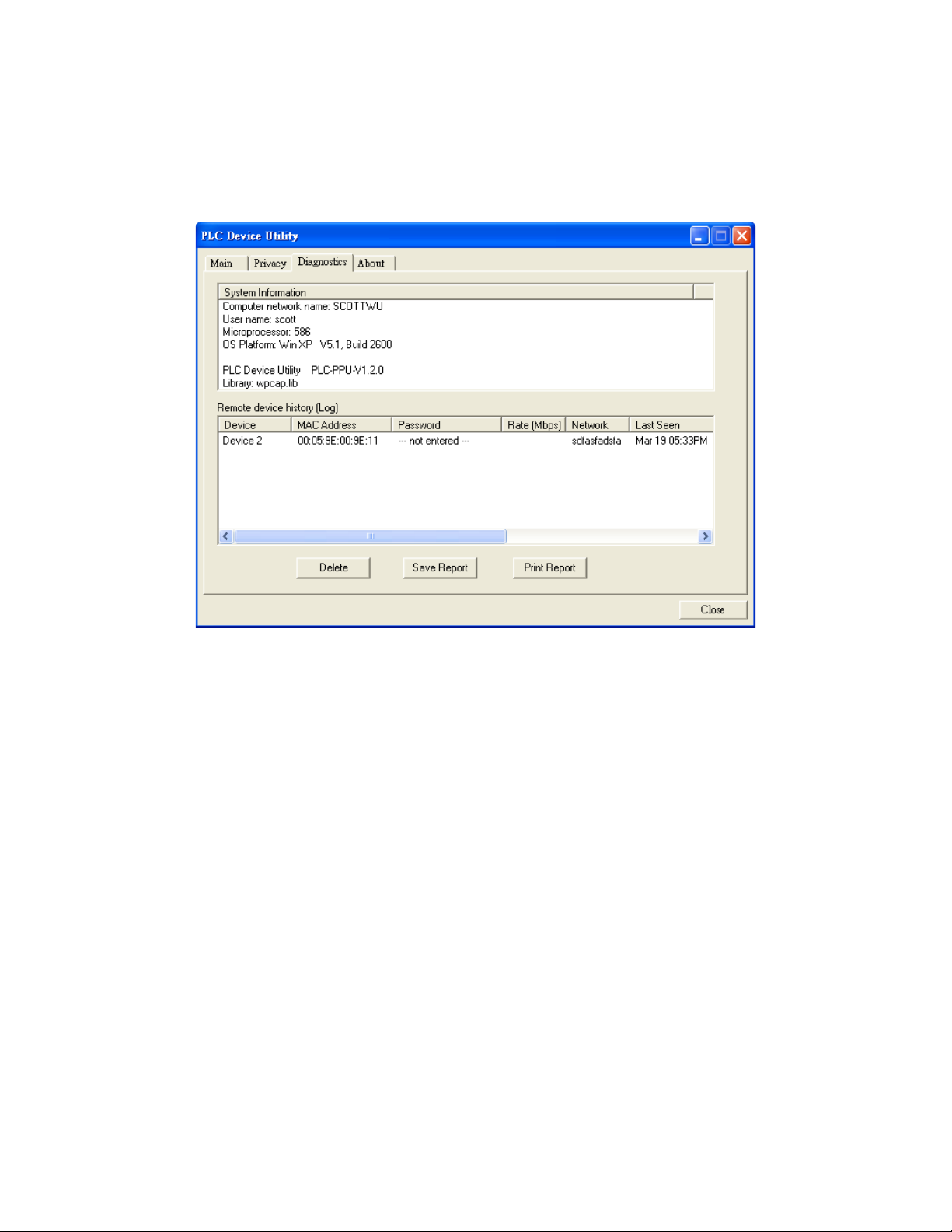
The Diagnostics pa ge shows System inf ormation and a histo ry of all remote devices seen ove r a period of
time. The appearance is shown in Figure 8.
Figure 8: Diagnostics Page
The Upper Subwindow shows software and hardware information of the management PC, including:
Computer name, User Name, Microprocessor, OS Platform/Version, PLC Device Utility version, and
library.
The Lower Subwindow, called the Remote device log window, contains a li st of all remote d ev ices whose
password has been entered into this software’s database. Each item contains the device password, its
MAC address and a few other parameters. The information displayed may be saved to a text file for later
use, or can be printed for reference for a technical support call.
By pushing the Delete button, the remote PLC devices whose password which were entered previously
will be cleared, and users won’t be able to change its Network Name through control buttons in Privacy
page. However, the device’s Network Name and its accessibility to the local device are still unchanged.
Page 8
Page 9
About page
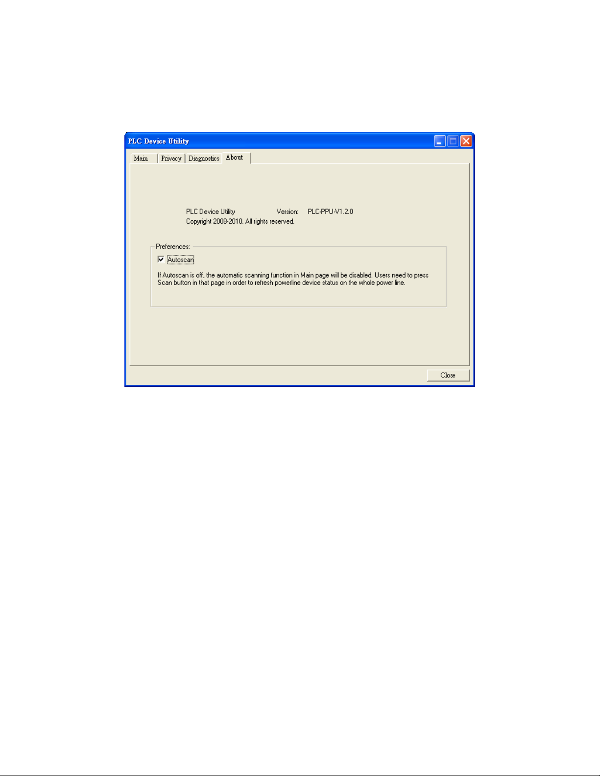
The About page, in Figure 9, shows the software version and provides AutoScan on or off selectio ns.
Figure 9: About dialog page
If AutoScan is turned ON (by default), the whole power line network will be scanned periodically to find all
remote devices accessible to the local PLC device and update the Remote Device Subwindow of Main
page. When AutoScan is OFF, users have to manual push the Scan button in Main page to update
remote device status.
Page 9
 Loading...