

Page 1

Page 2

Table of Content
1. Important Information........................................................................................................1
1.1 Important Safety Notes............................................................................................ 1
2. Introduction....................................................................................................................... 2
2.1 Package Content..................................................................................................... 2
2.2 LEDs Light Indicator Definition................................................................................. 2
3. Hardware Installation........................................................................................................5
3.1 Multiple Room Application ....................................................................................... 6
4. plugCAM App Installation.................................................................................................. 7
4.1 Interface Overview...................................................................................................7
4.2 Add Camera............................................................................................................. 8
4.2.1 QR Code Scan .............................................................................................. 8
4.2.2 Local Search.................................................................................................. 9
4.2.3 Add Manually................................................................................................. 9
4.2.4 Activate Your Camera.................................................................................. 10
4.3 View Images.......................................................................................................... 10
4.3.1 Take a Snapshot...........................................................................................11
4.3.2 Reload Camera ............................................................................................11
4.4 Cameras................................................................................................................ 12
4.4.1 Delete Camera ............................................................................................ 12
4.4.2 Camera Setting............................................................................................ 13
4.4.3 Time & Date................................................................................................. 14
4.5 Albums................................................................................................................... 15
4.5.1 View Albums................................................................................................ 15
4.5.2 Delete Albums ............................................................................................. 15
4.5.3 View & Delete, Email Pictures..................................................................... 16
4.6 App Settings .......................................................................................................... 17
4.6.1 Passcode lock ............................................................................................. 17
4.6.2 Background Skin ......................................................................................... 18
4.7 About..................................................................................................................... 18
5. PC Software Instruction.................................................................................................. 19
5.1 PC Software Installation ........................................................................................ 19
5.2 Function Introduction............................................................................................. 21
5.3 Search Camera in Local Network.......................................................................... 22
5.4 Add Camera Manually........................................................................................... 23
5.5 Edit Camera Basic Information, Alarm, and Recording Function........................... 24
5.5.1 Basic Information......................................................................................... 24
5.5.2 Alarm Setting ............................................................................................... 24
5.5.3 Full-time Alert............................................................................................... 25
5.5.4 Schedule Recording .................................................................................... 26
2
Page 3

5.6 plugCAM Software Disclaimer........................................................................ 28
6. Encrypted PLC Network.................................................................................................. 29
6.1 Creating a Private Encrypted Network................................................................... 29
6.2 Remove Device from an Existing Network Group.................................................. 29
6.3 Create Additional Private Network......................................................................... 30
7. Enhance PLC Performance............................................................................................ 31
8. Specifications.................................................................................................................. 33
3
Page 4

1. IMPORTANT INFORMATION
1.1 Important Safety Notes
The plugCAM is intended for connection to the AC power line. For installation instructions, refer to
the Installation section. The following precautions should be taken when using this product.
z Please read all instructions before installing and operating this product.
z Please keep all instructions for later reference.
z Please follow all warnings and instructions marked on the product.
z For safety reason, when device is being powered on, this product should NOT be
installed in any electric socket which makes the surface with venting holes on the
product to face downward (facing the floor).
z Unplug the Powerline device from the wall outlet before cleaning. Use a dry cloth for
cleaning. DO NOT use liquid cleaners or aerosol cleaners.
z DO NOT operate this product near water.
z This product should never be placed near or over a radiator, or heat register.
z This product relies on the building’s electrical installation for short-circuit (over current)
protection.
z DO NOT allow anything to rest on the product interconnect plug. DO NOT locates this product
where people may walk on the cords.
z Because this product sends data over the power line, it is recommended that you plug directly
into a power outlet. Do not plug the device into a UPS or power strip with surge protection. The
product has its own power filter for protection against surges.
z Only a qualified technician should service this product. Opening or removing covers may result
in exposure to dangerous voltage points or other risks.
z Unplug the product from the wall outlet and refer the product to qualified service personnel for
the following conditions:
¾ When the interconnect cords are damaged or frayed.
¾ If liquid has been spilled into the product.
¾ If the product has been exposed to rain or water.
¾ If the product does not operate normally when the operating instructions are followed.
¾ If the product exhibits a distinct change in performance.
1
Page 5
2. INTRODUCTION
The plugCAM home monitoring solution is the first of its kind using HomePlug AV-compliant
powerline communications (PLC) technology. The advanced Plug and Play Technology
automatically configures and connects the plugCAM Camera to the plugCAM App. After the
initial setup, you can begin viewing the area selected for monitoring right from your
smartphone, anytime, anywhere using the smartphone’s 3G, 4G, LTE or Wi-Fi connections.
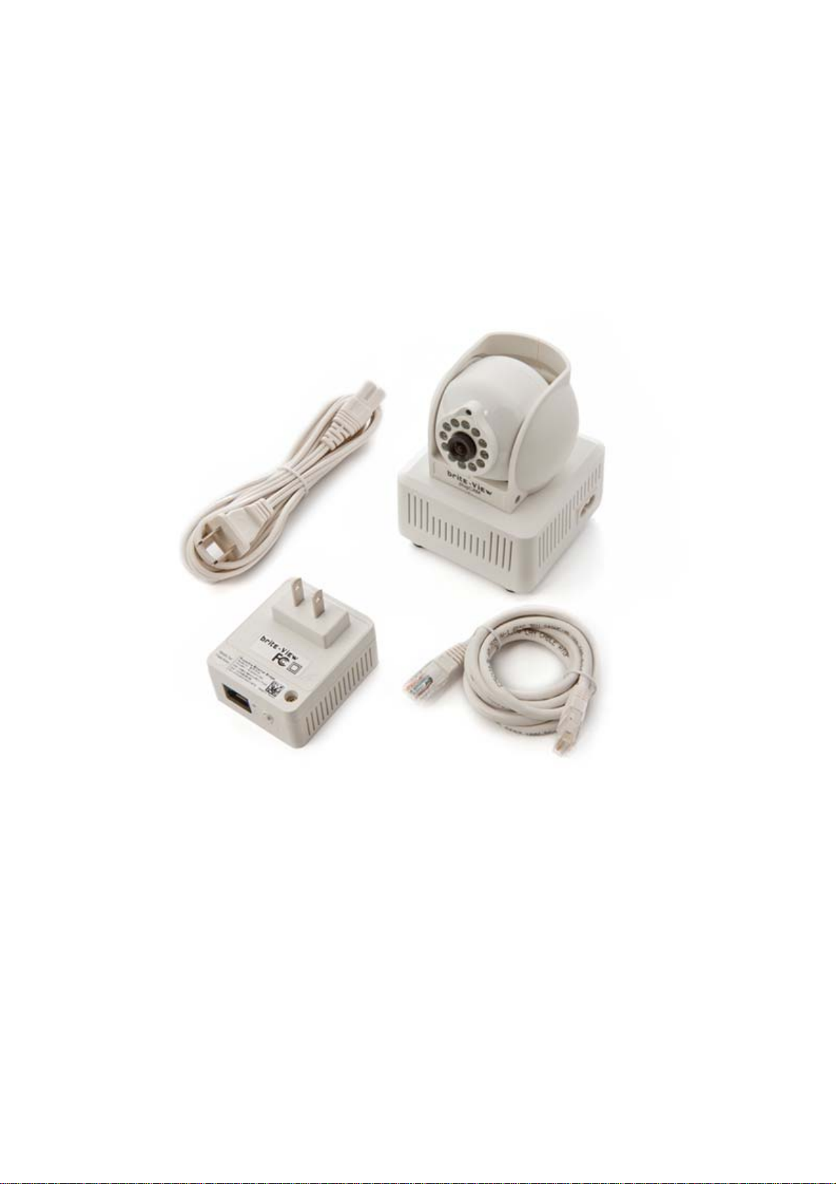
2.1 Package Content
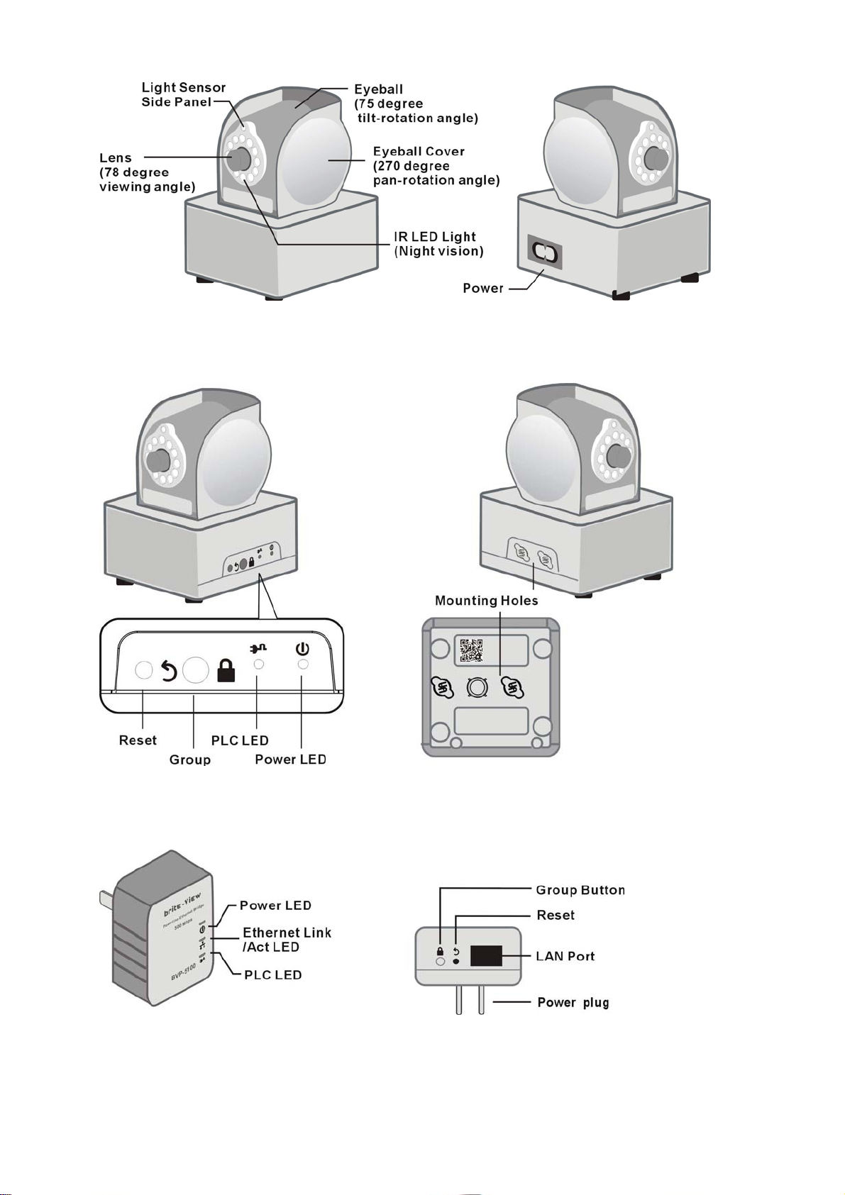
2.2 LEDs Light Indicator Definition
Before starting, please take few minutes to familiarize yourself with plugCAM.
2
Page 6
3
Page 7

Item Name
Eyeball
Cover
Eyeball
Lens
IR Light LED
Power LED
Description
Can rotate horizontally 135 degree to the right and to the left
Can rotate 0 to 75 degree, pointing the lens from horizontal to
nearly vertical
Lens with IR reflection coating
For night vision
ON: Power on and ready
Blinking:
1. During “Pairing Procedure” (creating an encrypted
PLC network). The device is creating or being joined into
the same encrypted network and will last 2 minutes until it
is been succeeded or canceled.
OFF: Power off.
PLC Act/Link
LED
Group Button
Reset Button
Figure-8 AC
connector
socket
OFF:
No PLC device is detected nor connected.
ON: PLC device is detected.
Blinking:
1. Fast: PLC UDP data transfer rate is higher than 60Mbps.
2. Normal: PLC UDP data transfer rate is between 10Mbps
to 60Mbps.
3. Slow: PLC UDP data transfer rate is slower than 10Mbps.
Press 1 to 3 seconds to enter into “Pairing Procedure”
(creating an encrypted PLC network).
While it’s under “Pairing Procedure”, press and hold for 2 to
3 seconds to stop the procedure.
Press and hold for 10 seconds to remove current encrypted
network and generate a new one.
Press and hold for over 1 second to reset factory default
AC Power cord
4
Page 8
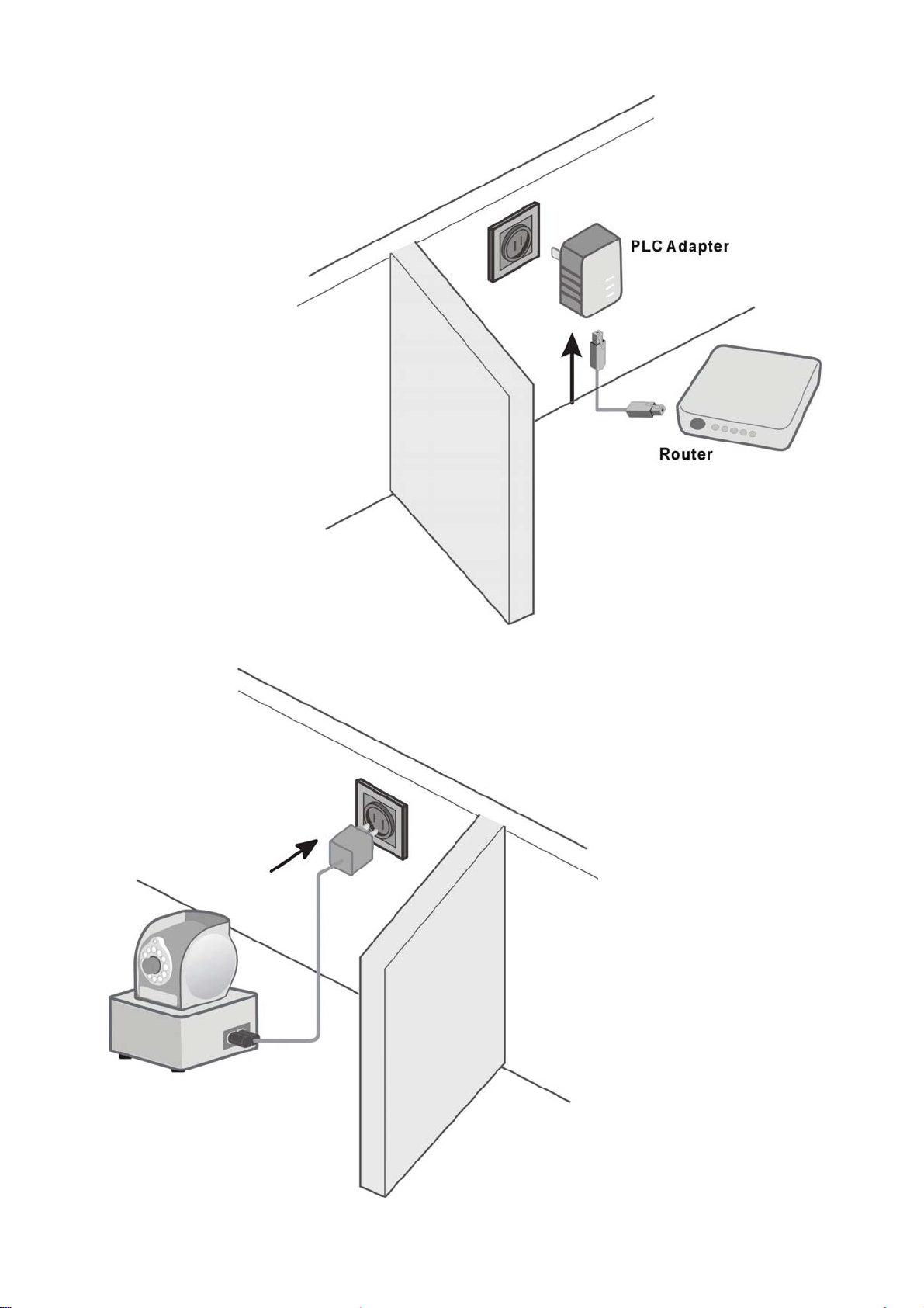
3. HARDWARE INSTALLATION
STEP 1: Connect PLC adapter
and router with Ethernet cable
STEP 2:
Place your plugCAM camera anywhere in the
house and power on camera. Then, the
plugCAM camera and PLC adapter will
automatically connected.
5
Page 9
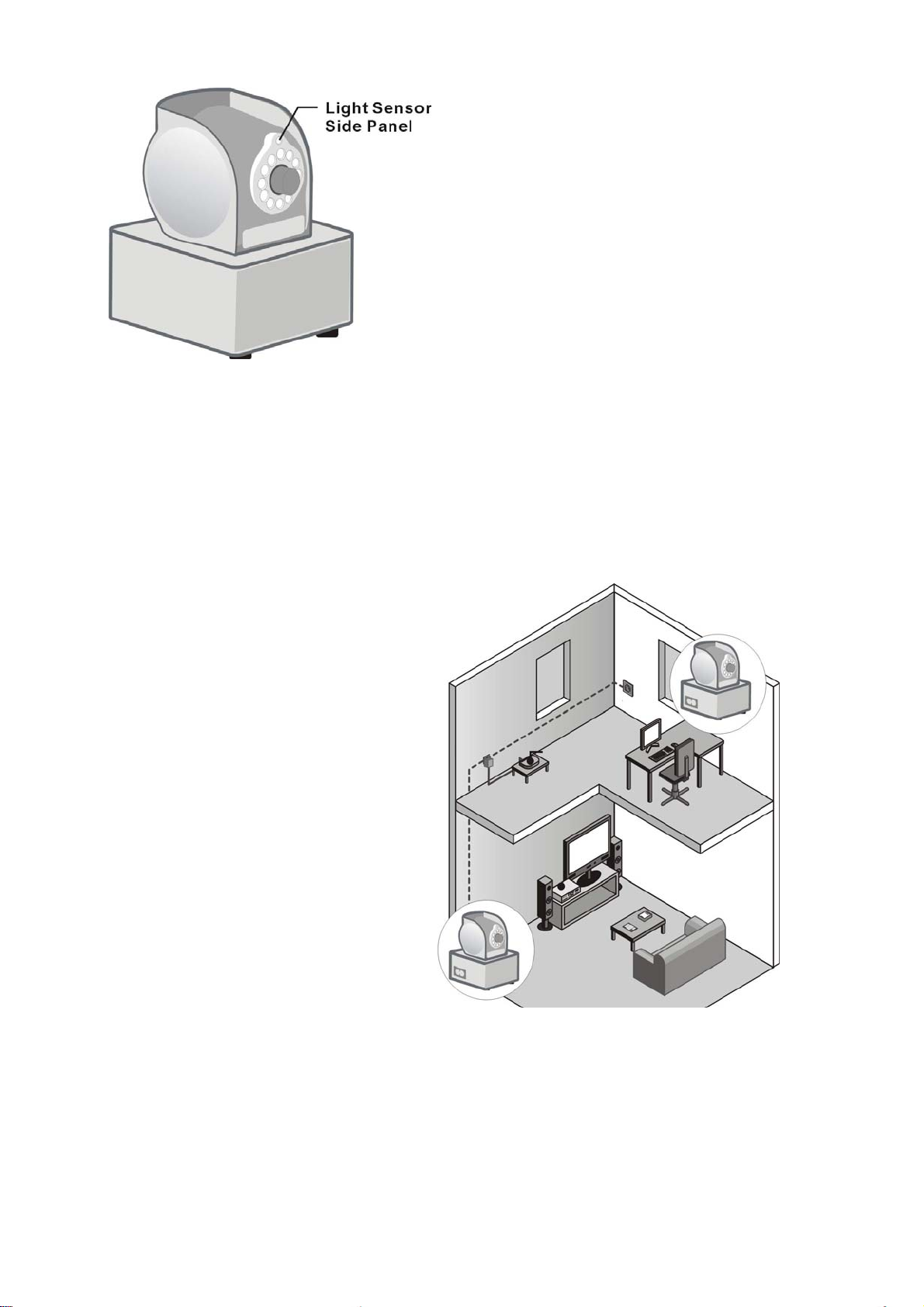
3.1 Multiple Room Application
One PLC adapter can work with up
to 7 cameras. You can place
additional cameras anywhere in the
While the camera is being accessed
(please see chapter “ Getting Started
“ to learn how to connect to your
camera), you may check if the camera
IR LED lights are working properly by
covering the light sensor above lens
and see if IR LED bulbs turn red.
house. Simply plug additional
camera into wall outlet, then PLC
adapter will automatically detect
and connect to new camera. If
existing PLC adapter has
established private encryption
network, you can press “Group”
button on PLC adapter and new
camera, then new camera will join
to its encryption network.
6
Page 10
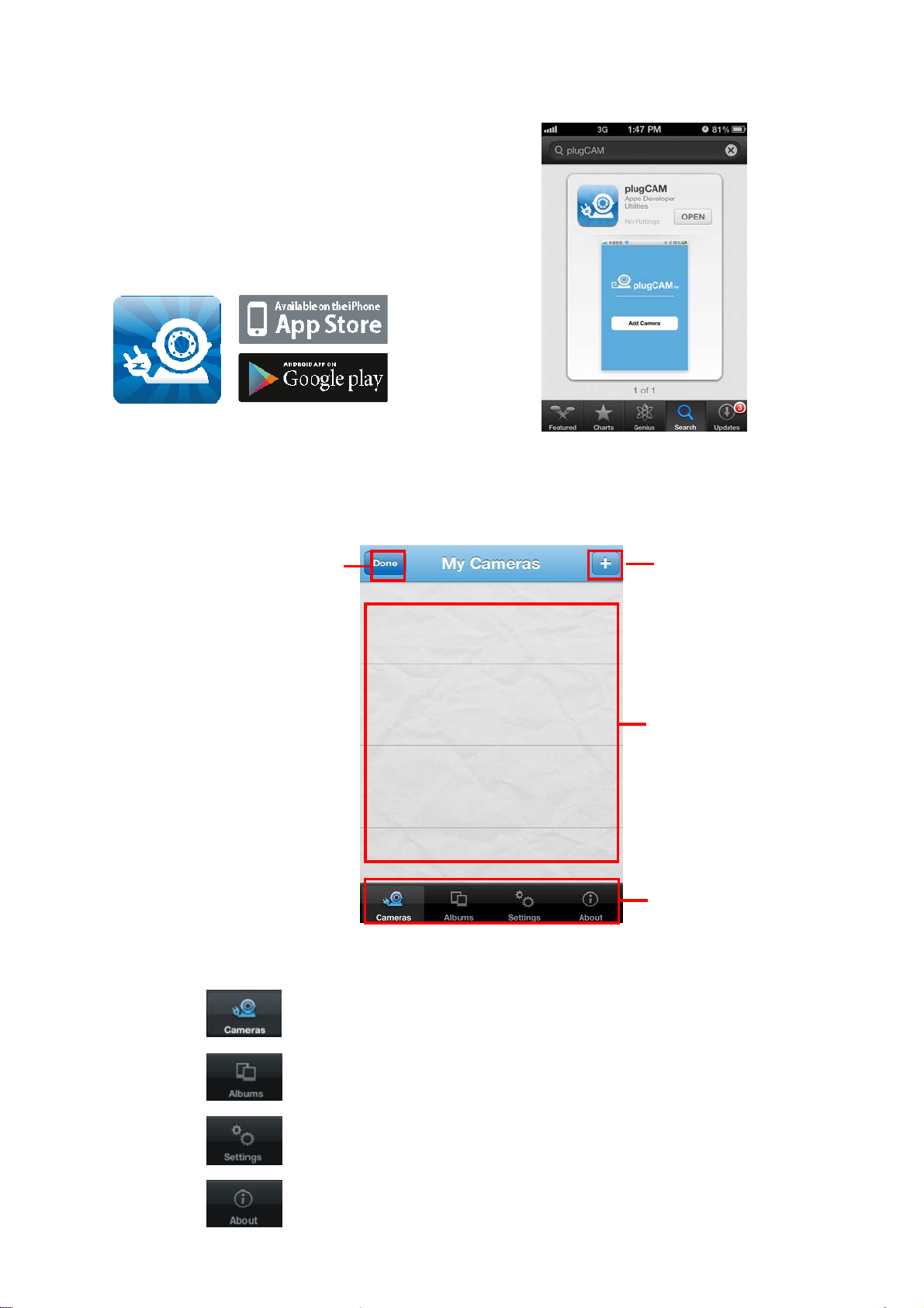
4. PLUGCAM APP INSTALLATION
Free “plugCAM” App
You can search the free “plugCAM” App on
Apple store or Google Play
4.1 Interface Overview
Main Screen
Delete selected items
Add new camera
Camera list
Tool bar
Show camera list, delete or add new camera.
Show album list, view and delete pictures from individual camera
Change App settings
Show App and plugCAM information
7
Page 11
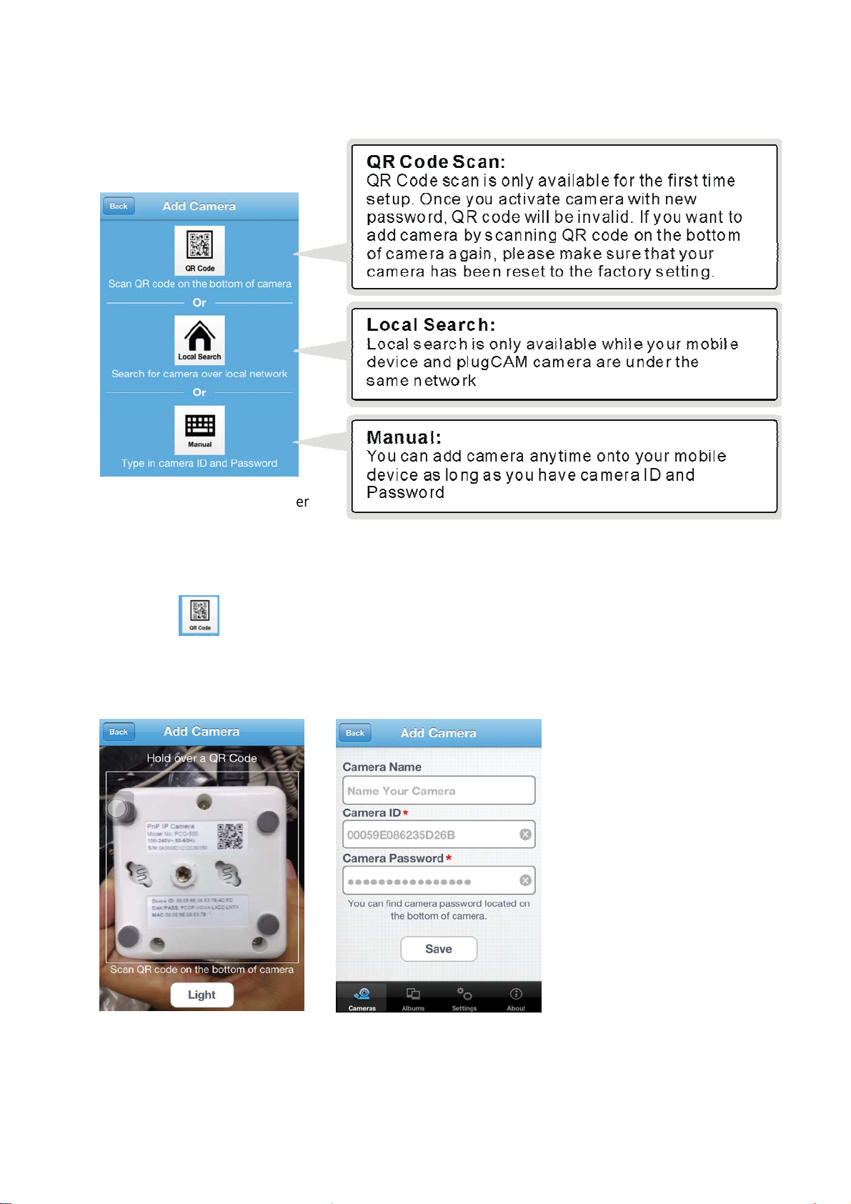
4.2 Add Camera
- To add camera onto your smartphone, there 3 options to add camera, “QR Code Scan”,
“Local Search” and “Manual”
P.S. Each plugCAM PLC adapter
can support up to 7 plugCAMs.
4.2.1 QR Code Scan
1. Tap on to start QR code scan.
2. Scan the QR code that is located on the bottom of plugCAM.
3. “Save” to camera list
8
Page 12
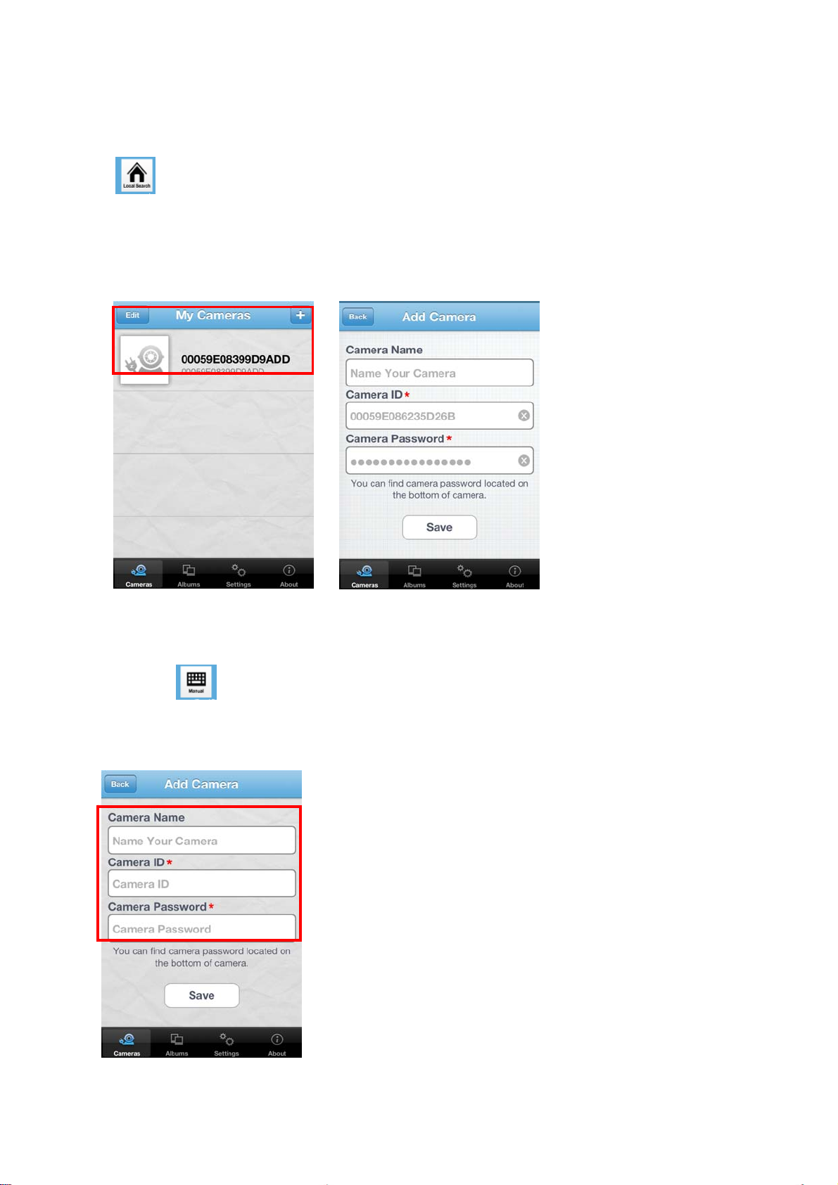
4.2.2 Local Search
1. Make sure your camera and mobile device are under the same network, then tap on
to search new camera. Once new camera is found, you can select the camera you
want to add.
2. Enter camera password
3. “Save” to camera list
4.2.3 Add Manually
1. Tap on
2. Type Camera ID and Password
3. “Save” to camera list
9
Page 13
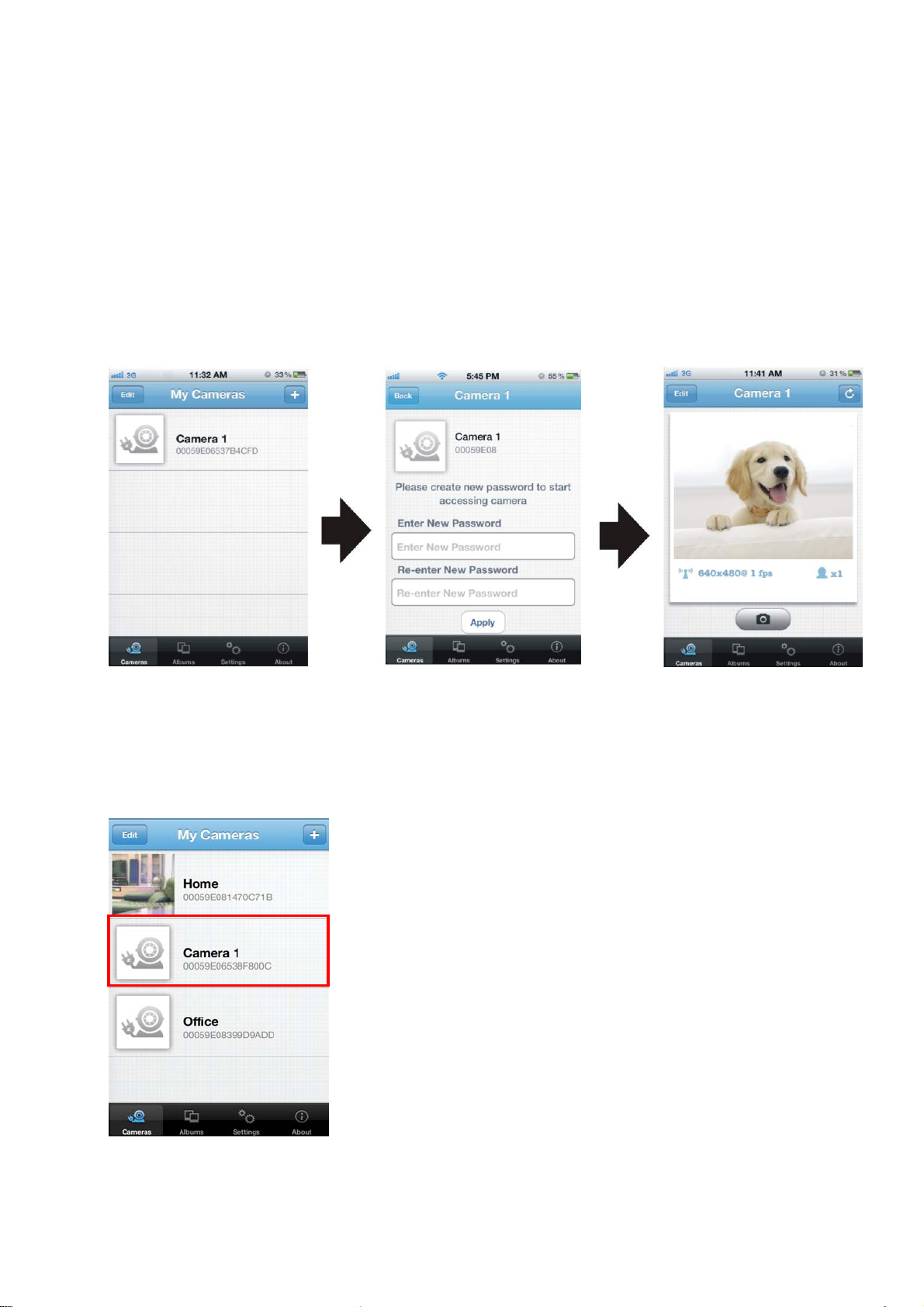
4.2.4 Activate Y our Camera
Step 1: Connect to the camera with the default password.
Step 2: You will need to create new password and press apply button on the screen before
accessing your camera.
PS: For the safety purpose, you will be asked to create new password when you connect to camera with the
default password.
4.3 View Images
1. Select a camera from the camera list
10
Page 14
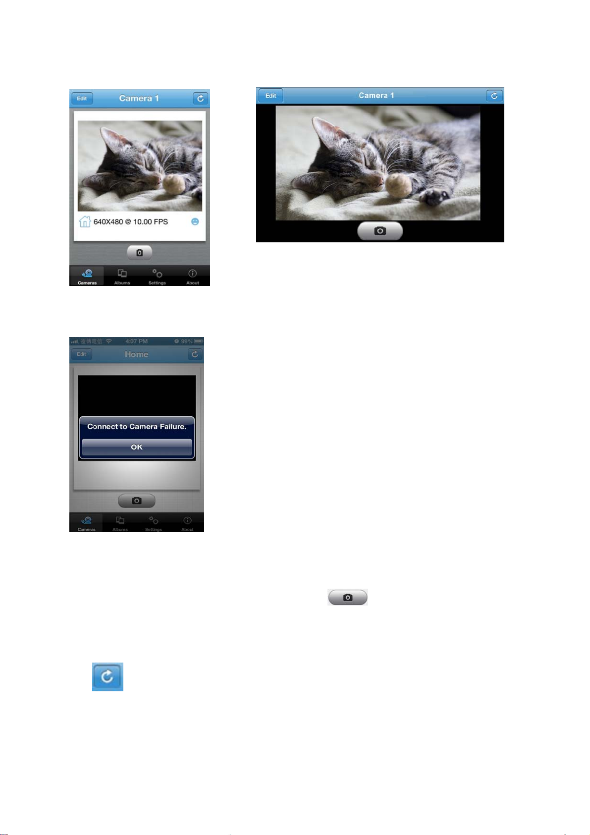
2. If ID and Password are all correct, plugCAM App will start loading camera image
3. If the camera is offline, please check if you have installed the camera properly
4.3.1 Take a Snapshot
1. While accessing the camera, you can tap the icon to take a quick shot.
2. The pictures will be saved to album.
4.3.2 Reload Camera
Tap to reload the camera image
11
Page 15
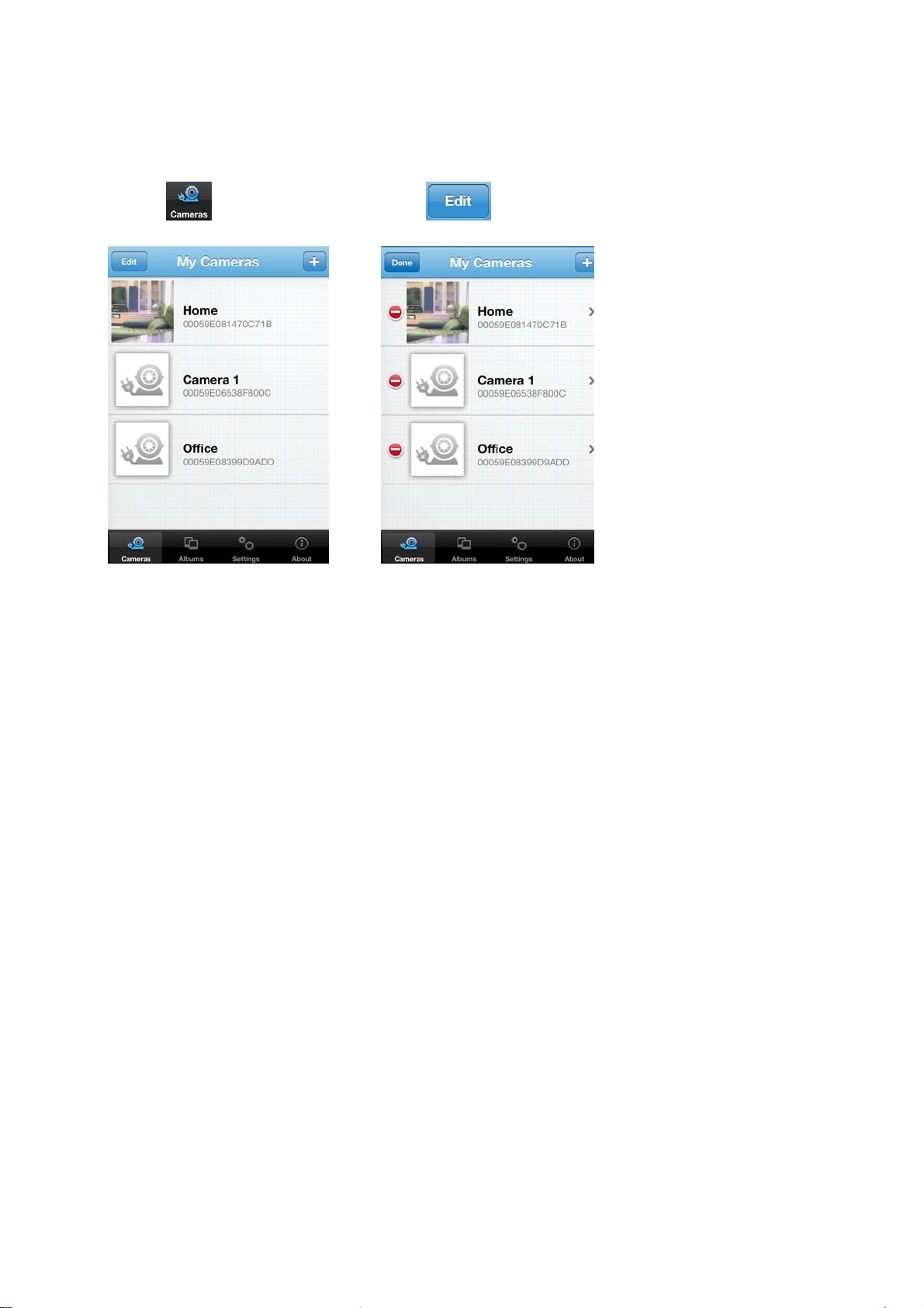
4.4 Cameras
4.4.1 Delete Camera
1. Tap to show camera list, Tap to delete camera
12
Page 16
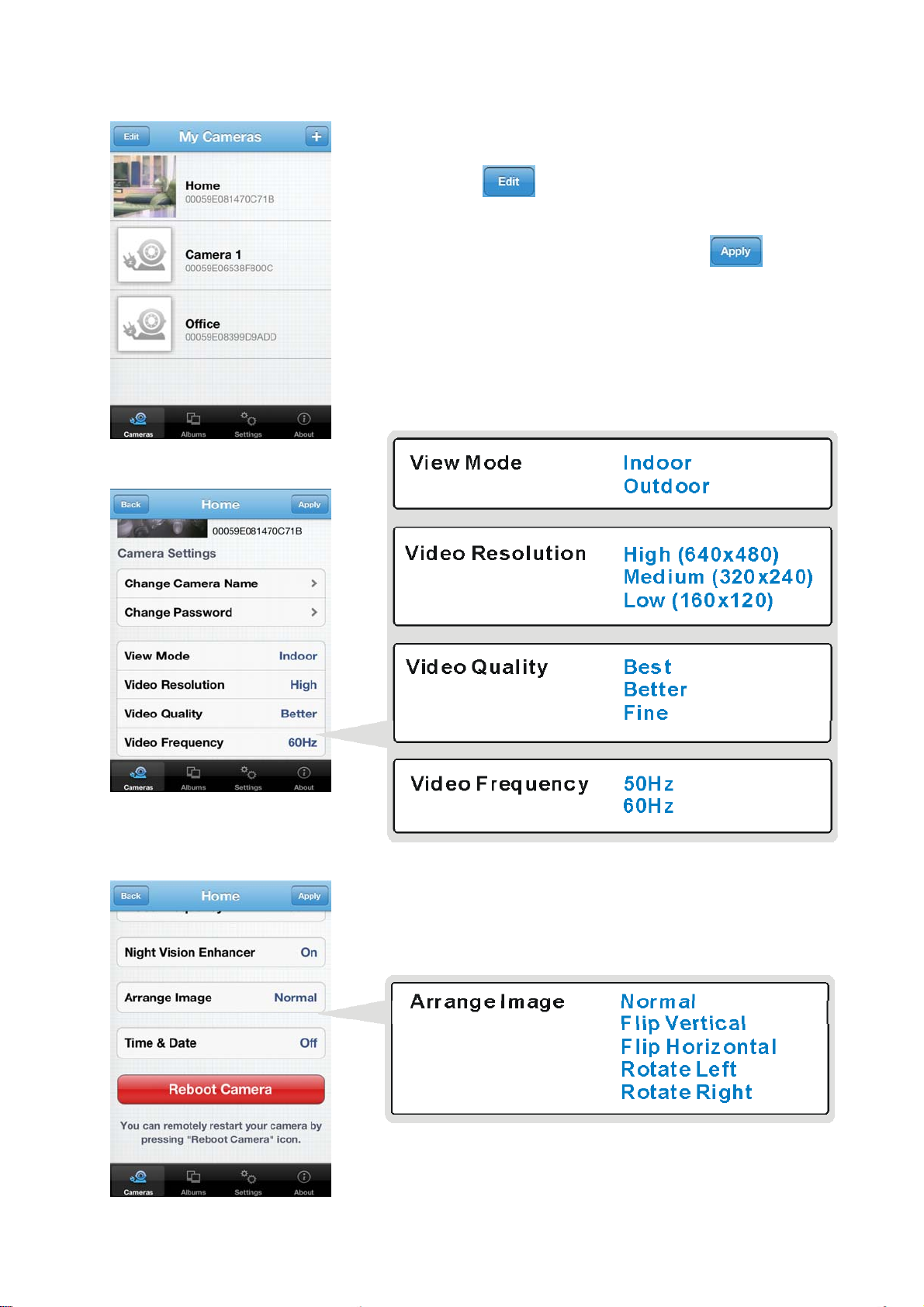
4.4.2 Camera Setting
1. Select a camera
2. Tap to enter the camera settings
3. After make changes, please tap on
to save each change.
13
Page 17
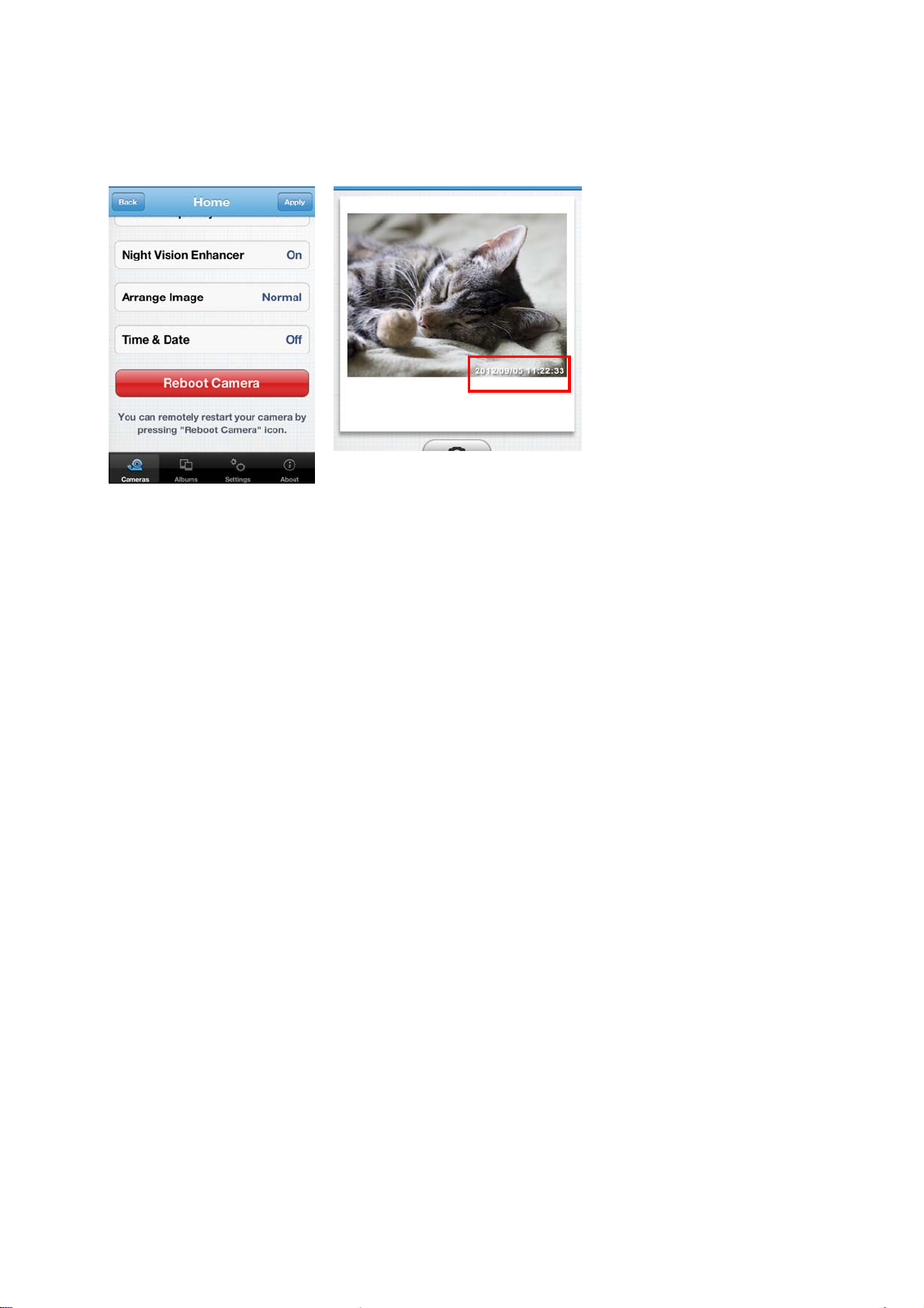
4.4.3 Time & Date
1. The default setting is Off, tap “On” to turn on time & date information
2. Tap “Done” to confirm, then time & date will show up on the viewing screen
14
Page 18
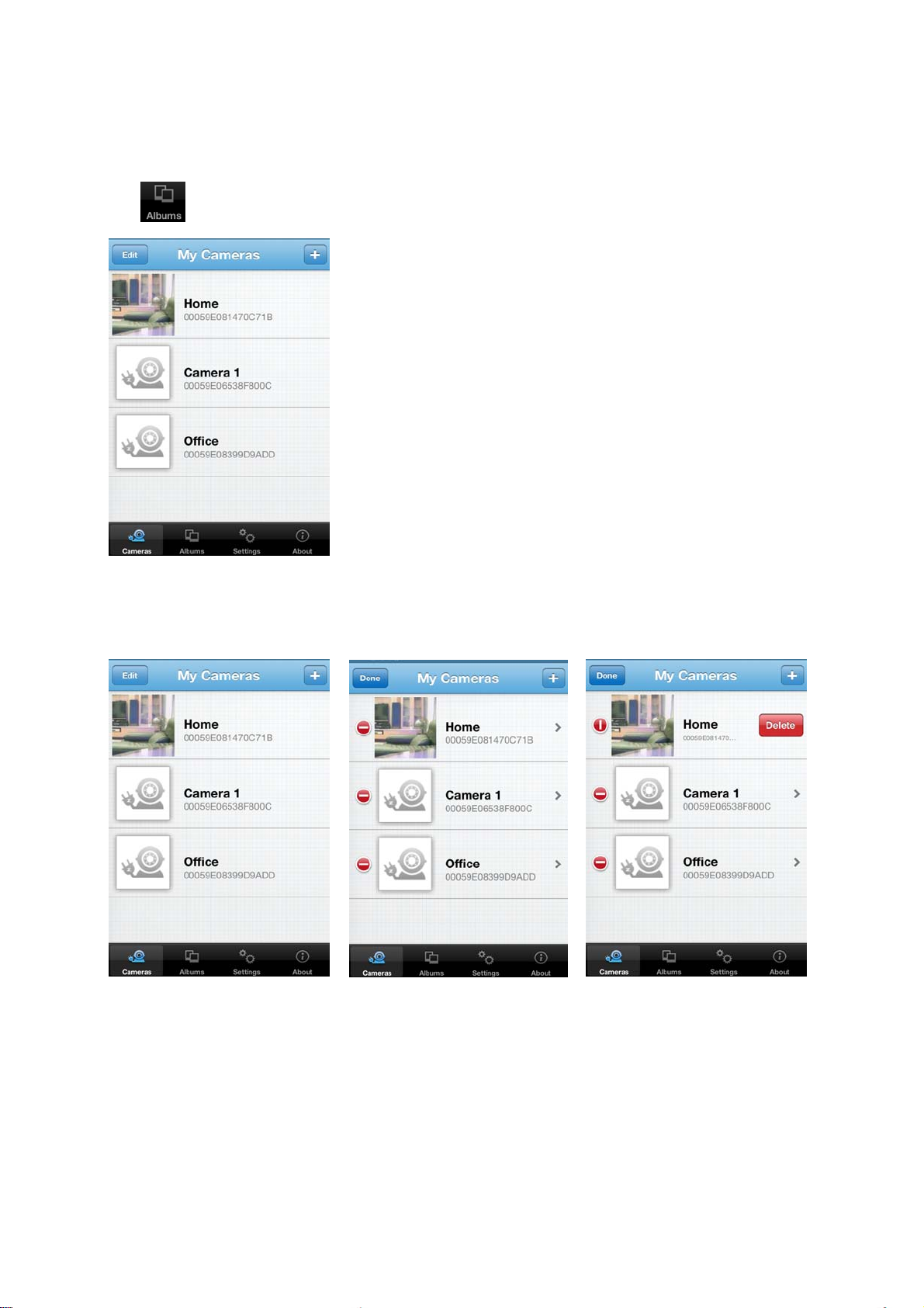
4.5 Albums
4.5.1 View Albums
Tap to start
4.5.2 Delete Albums
1. “Edit” > “Delete” > “Done” to confirm
15
Page 19
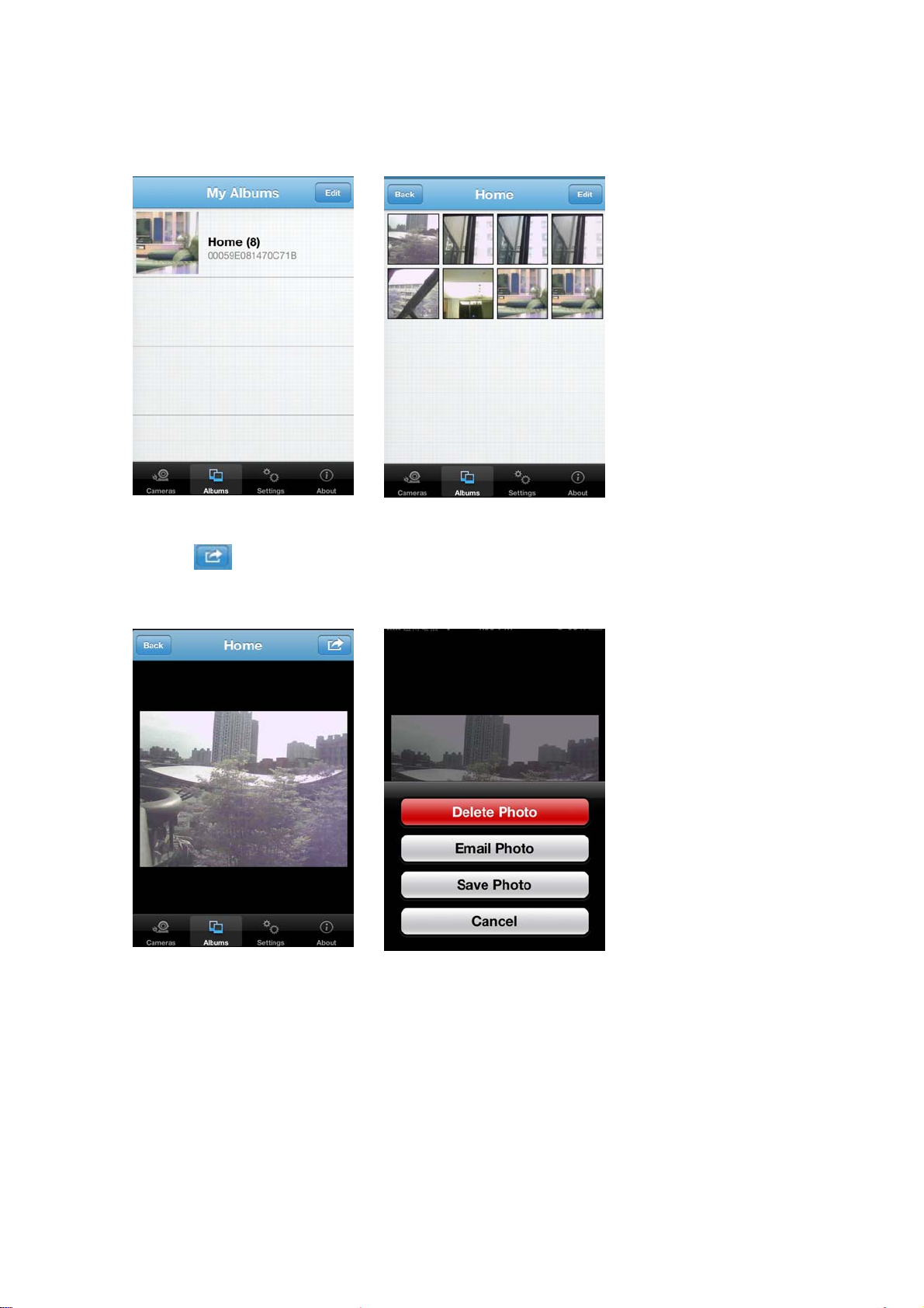
4.5.3 View & Delete, Email Pictures
1. Select an album
2. Tap on the picture you want to see for larger view
3. Tap on to Delete, Email, and Save picture
If your don’t want to do any change, just press “Cancel “ to go back
16
Page 20
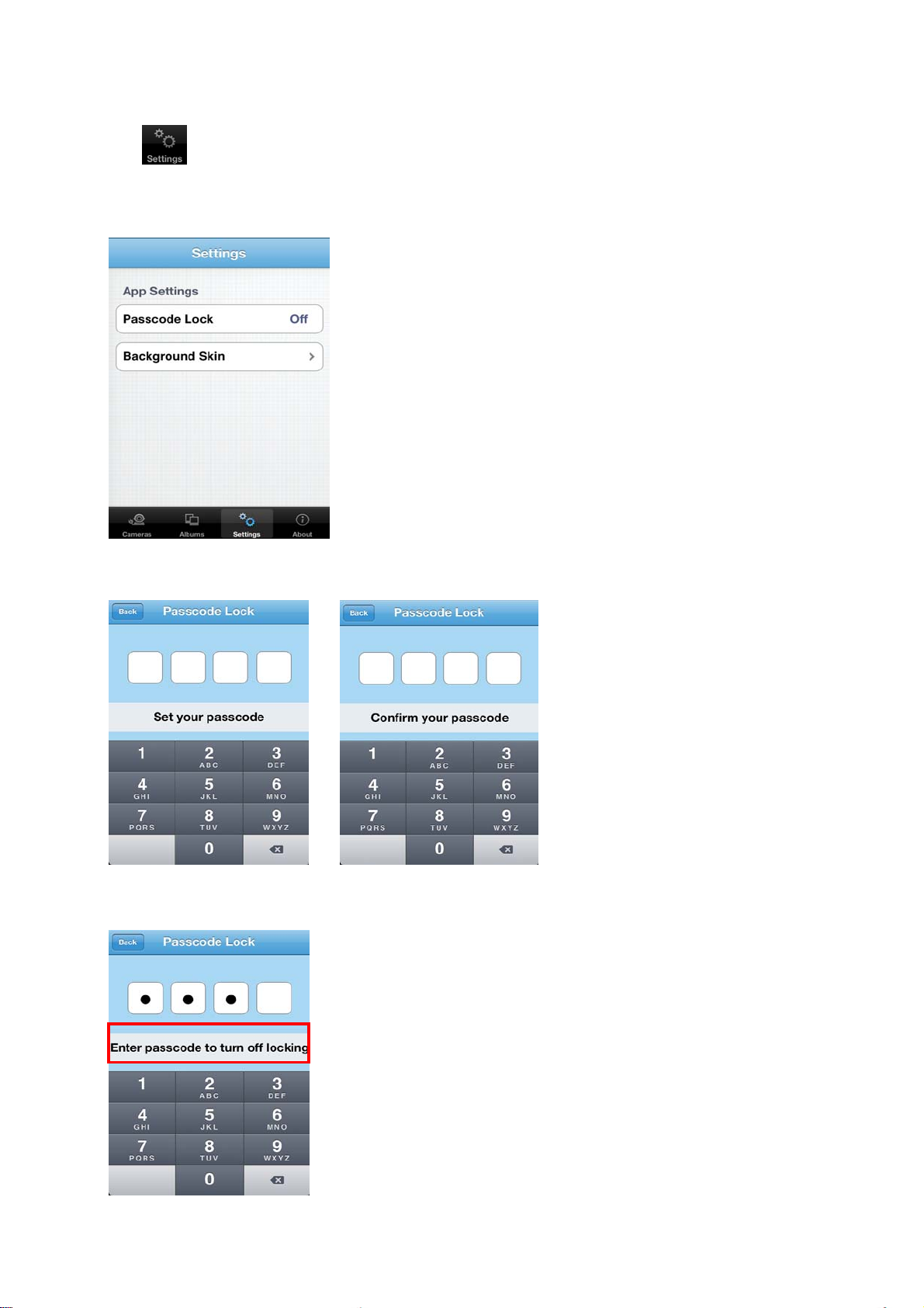
4.6 App Settings
Tap to start
4.6.1 Passcode lock
Default setting is “Off”.
Turn on “Passcode Lock” can help prevent others connect
to your plugCAM without your permission.
You must enter correct passcode every time when
starting the plugCAM program after turning on this
function.
Turn on Passcode
Turn off Passcode
1. Tap on the Passcode Lock
2. Enter passcode and confirm it
again
1. Tap on the passcode lock
2. Enter passcode again to turn off passcode lock
17
Page 21
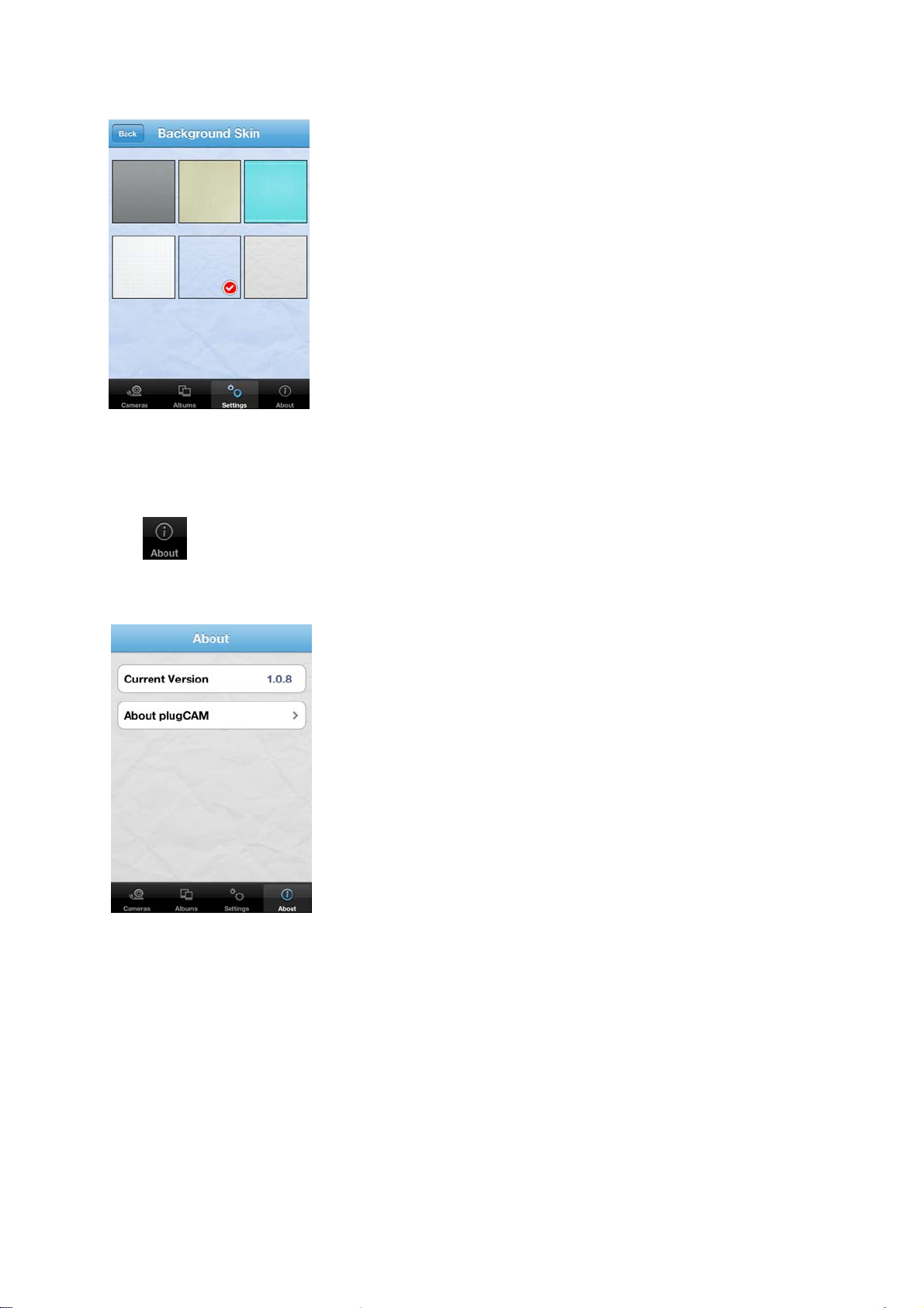
4.6.2 Background Skin
4.7 About
1. Tap on Background skin
2. Default is gray. Choose a color for your background
Tap to start
Show Software Version & Product Information
18
Page 22
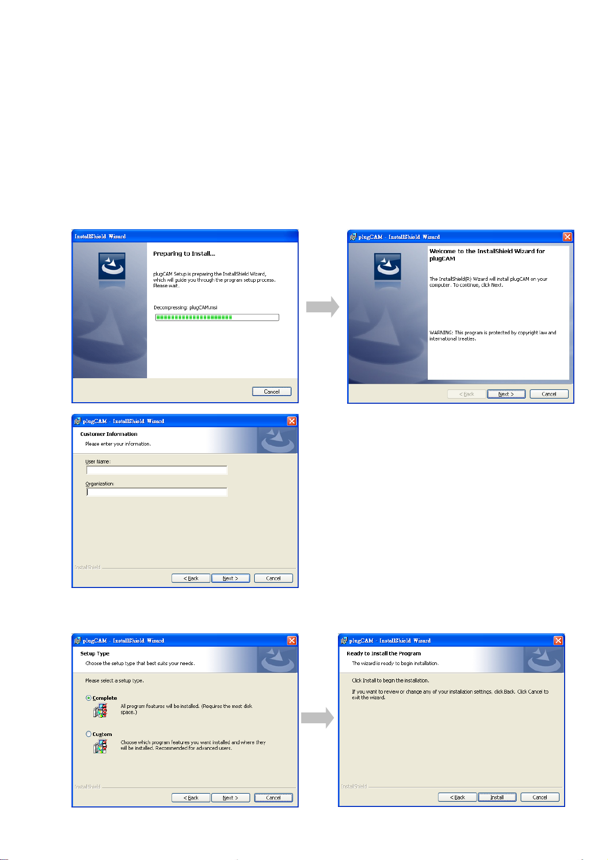
5. PC SOFTWARE INSTRUCTION
5.1 PC Software Installation
Insert the software CD to your CD-R device or download from the official website to start the
installation.
1. Double click to start installation
2. Set-up will start automatically
3. Click “ Next > ” to enter PC information
4. Choose set-up type and click “ Next > “ to enter installation procedure
19
Page 23
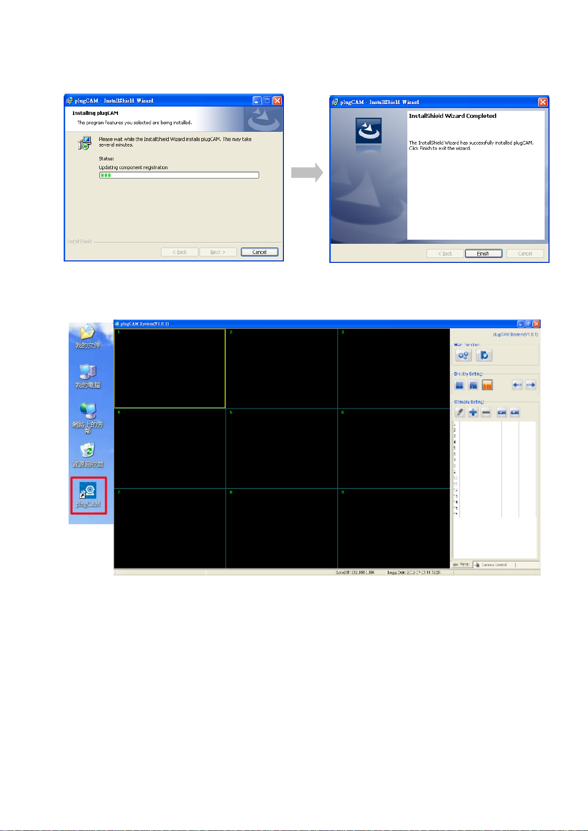
5. Procedure complete automatically
6. You can see the plugCAM program and the icon after installation successfully
Shortcut on desktop
Program main screen
20
Page 24
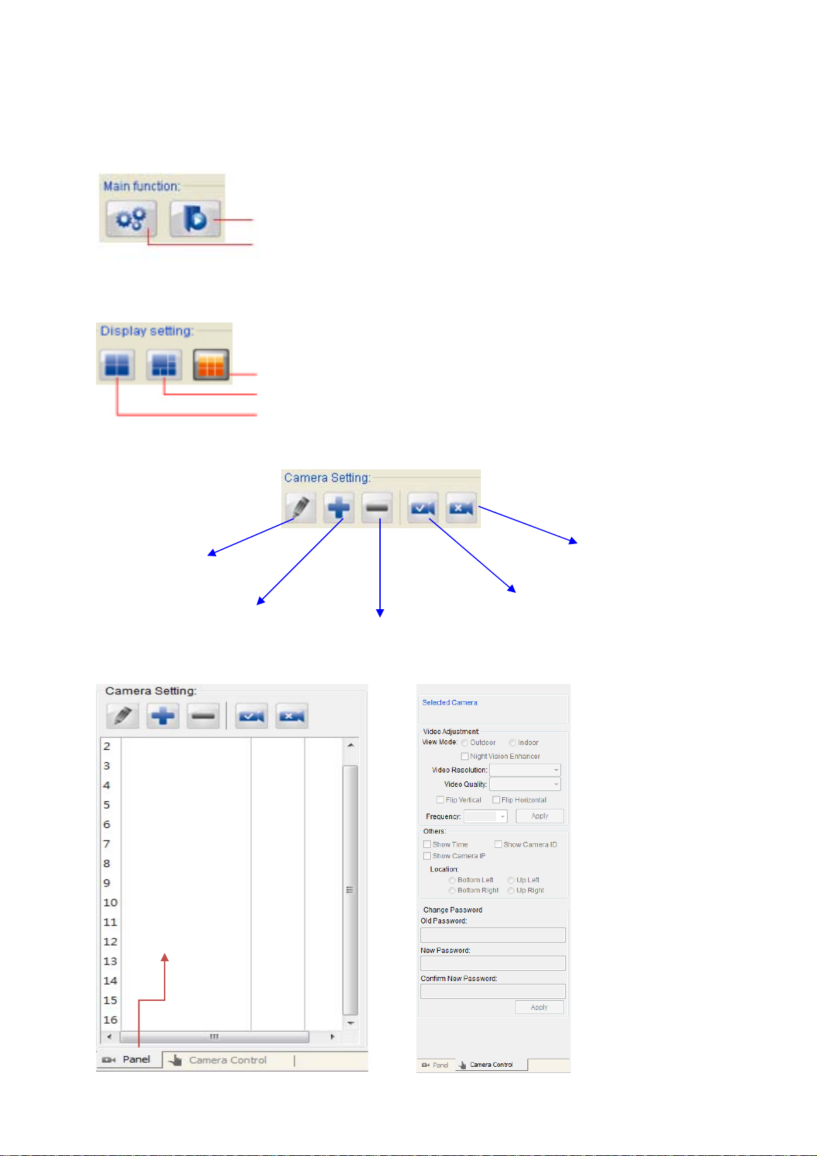
5.2 Function Introduction
Main Function
Playback video recording
Set snapshot and video recording path
Display Setting
Camera Settings
9 channels (default)
6 channels
4 channels
Edit alarm / recording settings
Add new camera
Edit Camera Basic
Information, Alarm, and
Recording Function
Disconnect all cameras
Connect to all cameras
Delete selected camera
21
Page 25
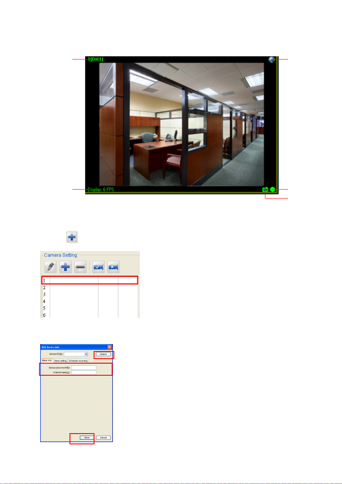
Display Channel
Channel name
Video frame rate
5.3 Search Camera in Local Network
1. Select an empty channel
Remote viewing
Video recording
Snapshot
2. Click to add in a new plugCAM device
3. Click search to find plugCAM in the same network, wait for plugCAM ID shows up, and
then type in password, press “ Save “.
22
Page 26
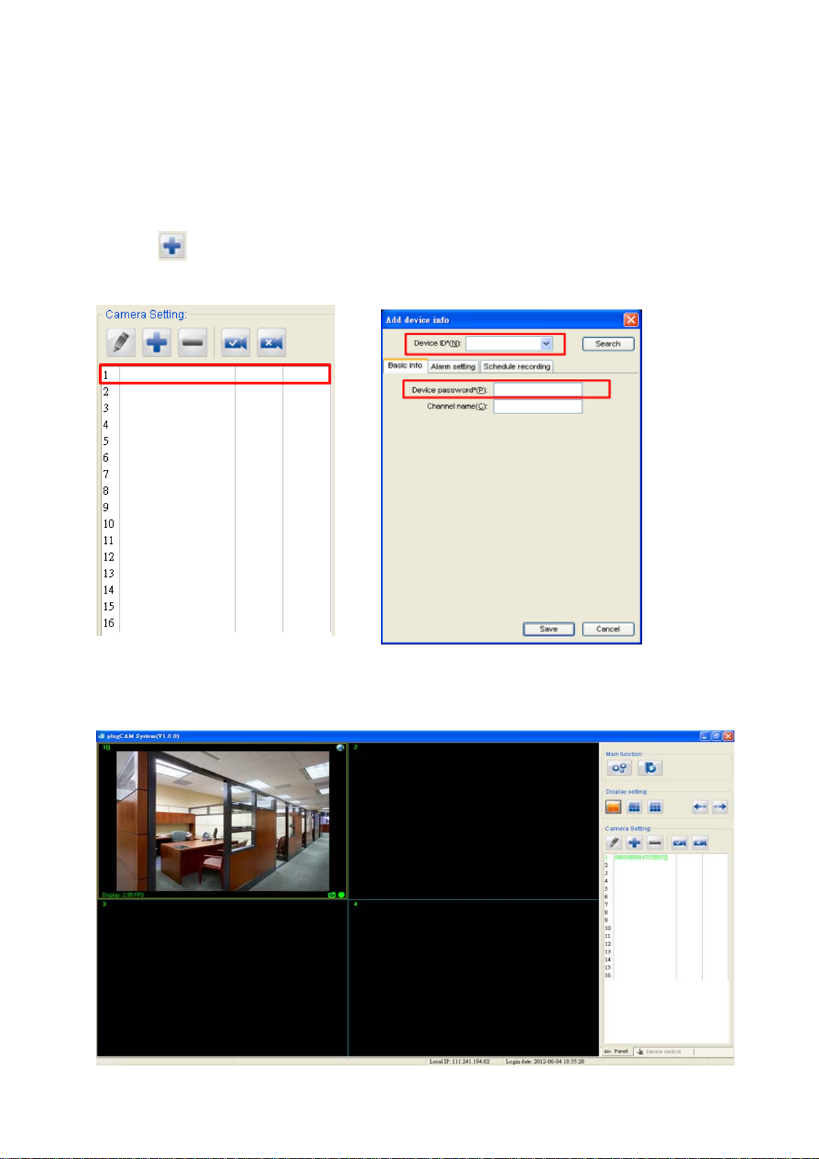
4. Click selected channel to connect to camera
5. plugCAM image will show on the display channel
5.4 Add Camera Manually
1. Select an empty channel
2. Click to add in a new plugCAM device
3. Type in ID and password, press “Save”.
4. Click selected channel to connect to camera.
5. plugCAM image will show on the display channel
23
Page 27
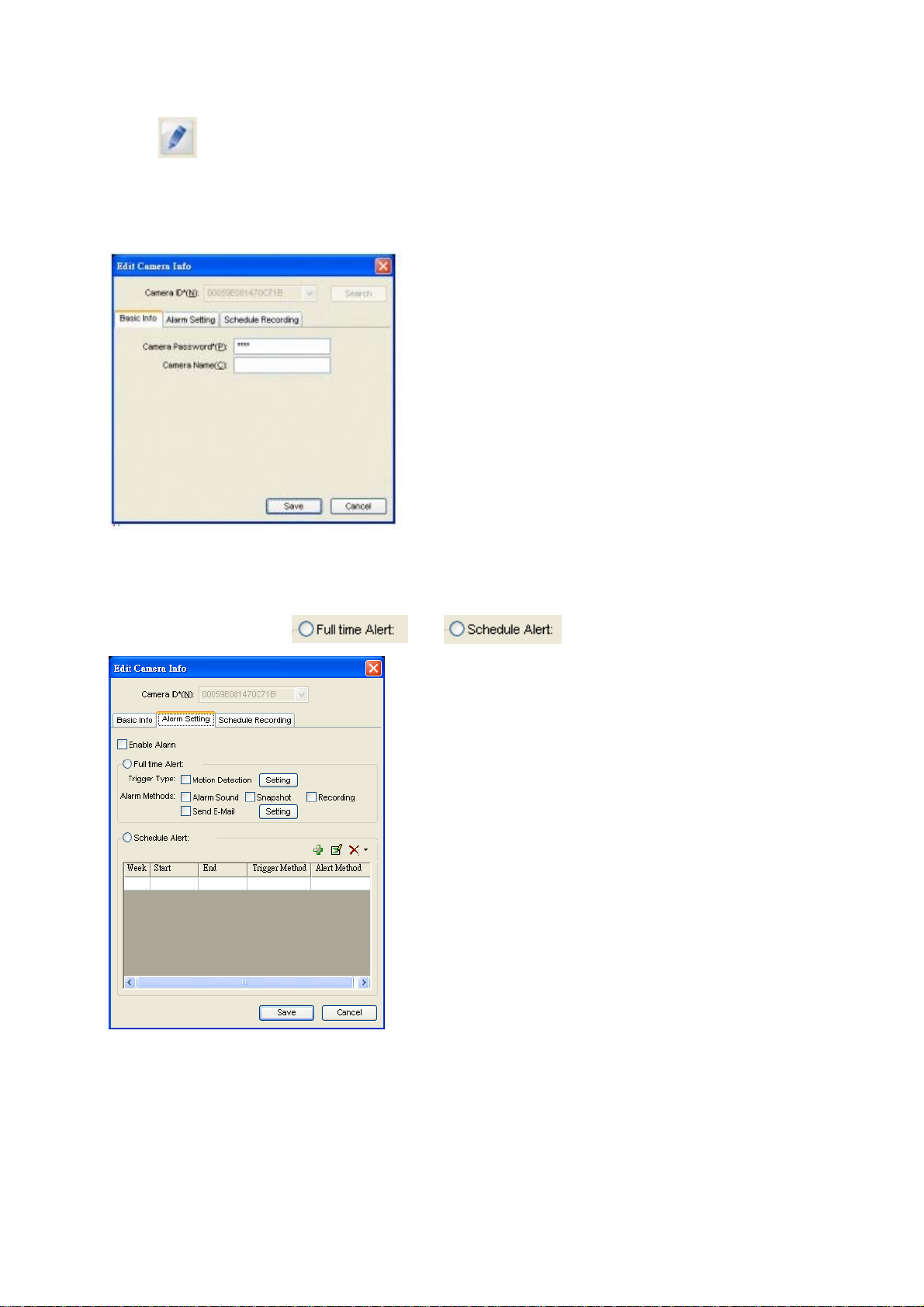
5.5 Edit Camera Basic Information, Alarm, and Recording Function
Click for setting up basic info, recording, motion detection, and email alert…etc
5.5.1 Basic Information
Change password and name of selected plugCAM
5.5.2 Alarm Setting
Enable alarm: choose or
24
Page 28
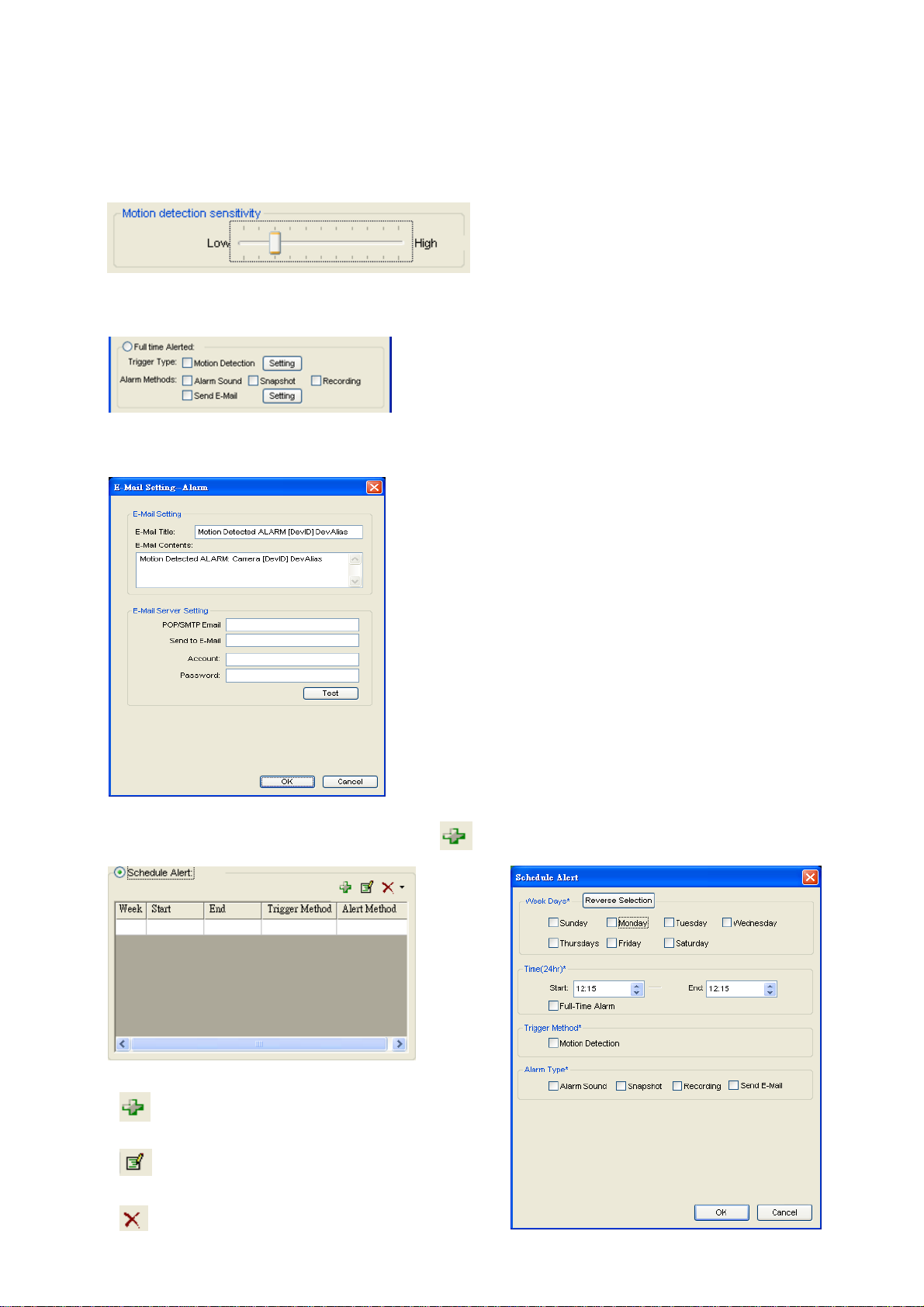
5.5.3 Full-time Alert
If you want to set Full-time Alert, you may adjust the sensitivity by clicking the setting button
of Motion Detection
Then set Alarm Methods: Alarm sound, Snapshot, Recording, Send E-mail
Clicking the Setting button to enter E-mail address
If you want to set Schedule Alert, click for further settings.
add duration
edit selected duration
delete selected duration
25
Page 29
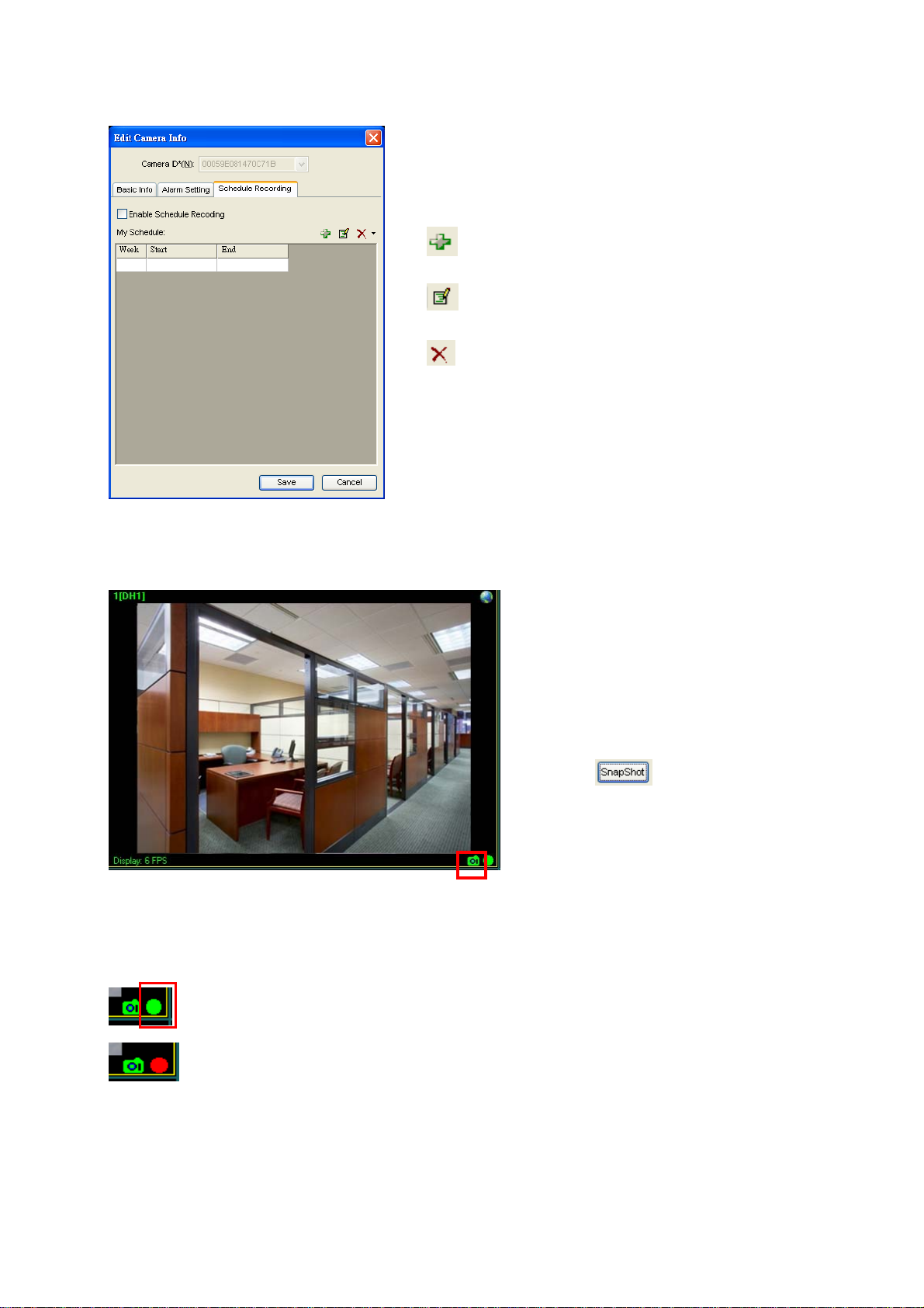
5.5.4 Schedule Recording
5.5.4.1 Take Snapshot
to add duration
to edit selected duration
to delete selected duration
1. Click the snapshot button to take
snapshot from the camera
2. You can see the picture you take
immediately; you can also open the file
folder to delete snapshots.
3. Press
picture
5.5.4.2 Recording Video
Press the record button to start recording.
Turning red means that camera is under
To stop recording, click again and the button will be back to green.
again to take another
26
Page 30
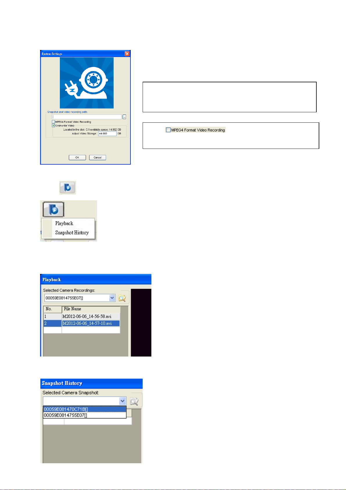
5.5.4.3 Set Snapshot and Video Recording Path
Click to choose a folder that you want to save pictures
and videos
Start to activate MPEG 4
recording.
Click to show history of video or snapshot
5.5.4.4 Playback Saved Videos
5.5.4.5 Show Snapshot History
1. Click on ‘Playback’, then choose a
camera to see its record
2. After you choose a camera, you will
see the recorded video list; pick one to
review
1. Click on “Snapshot History”, then choose
a camera to see its record
2. After you choose a camera, you will see
the recorded snapshot list; pick one to
review
27
Page 31

5.6 plugCAM Software Disclaimer
This plugCAM product integrated with PC Software may support recording function and alert function.
Notwithstanding, brite-View Corporation does not represent or warrant the accuracy or reliability of
any of the function, content, setting or setup contained on, distributed through, or linked, downloaded
or accessed from any of the services or functions provided by the plugCAM product. Customers
hereby acknowledge that any usage or reliance upon the plugCAM product shall be at customers’
sole risk. brite-View Corporation hereby reserves the right, in its sole discretion and without any prior
notice or obligation, to make improvements to, or correct any error or bugs in any portion of the
plugCAM product
28
Page 32

6. ENCRYPTED PLC NETWORK
6.1 Creating a Private Encrypted Network
Both the plugCAM and the Powerline bridge are compliant HomePlug AV specification. Every
‘HomePlug AV’ compliant PLC device that has the same default network name, “HomePlug AV”, is
capable of communicating with other “HomePlug AV” devices. This is so called the “Public Network”.
Two or more powerline devices under the same network can communicate with one another.
If you have a pair of powerline device, either one in the pair can be “device A” or “device B”. By
pressing the GROUP button more than 10 seconds; it will generate a random network group
(different from HomePlug AV). Users can take the following two steps to change the public network
group to the private network group to protect their data while transmitting over the powerline. Users
also can create more than one private network groups by pressing GROUP button directly without
software installation required.
*NOTE: Put the devices side by side will be more convenient during the setting procedure. After network group
is set, the devices can be deployed anywhere at home.
Step I: Clear Group Attribute
Clear the original network group of device B by pressing its GROUP button more than 10 seconds
until all LED lights simultaneously turns off and on once. At this moment, its network group name has
been changed to a random name. It means that this device is (1) ready to be assigned another
network name or (2) to be used as a seed device so other PLC devices can join to a private
network group.
Step II: Join to Other Network Group
1. Press GROUP button of device A for 2 to 3 seconds (make sure POWER LED starts blinking).
2. Press GROUP button of device B for 2 to 3 seconds (make sure POWER LED starts blinking).
The device B which has cleared its group attribute will join to the device A which has not. This step
makes device A and B are under the same encrypted network. Additional device C can be added into
device A’s logical network by taking same steps, thus all of the device A, B, and C in the same
encrypted network group. User can assign as many powerline devices into the logical network group
as described in the SPECIFICATION section.
*NOTE:
button within two minutes after pressing first device’s GROUP button. After 10 seconds, device will start
communicating with device A.
It does not matter which device’s button is pressed first, but please press the secon d device’ s GROUP
6.2 Remove Device from an Existing Network Group
If you would like to remove powerline device from an existing network group, you can generate a new
29
Page 33

group name (referring to Step I) to stop communication with an existing network group.
6.3 Create Additional Private Network
If you want to create additional private network for your powerline devices that co-existence with your
existing powerline private network group, please repeat the Step 1 & 2 to generate new private
network group for selected powerline devices.
P.S. Users can press the RESET button to reset the network name back to its factory default.
30
Page 34
7. ENHANCE PLC PERFORMANCE
While Powerline device delivers data over the existing electrical wiring in the house, the actual
performance may be affected by electrical noises or the length of the wiring. To improve PLC
performance, please refer to below recommendations while placing the Powerline device.
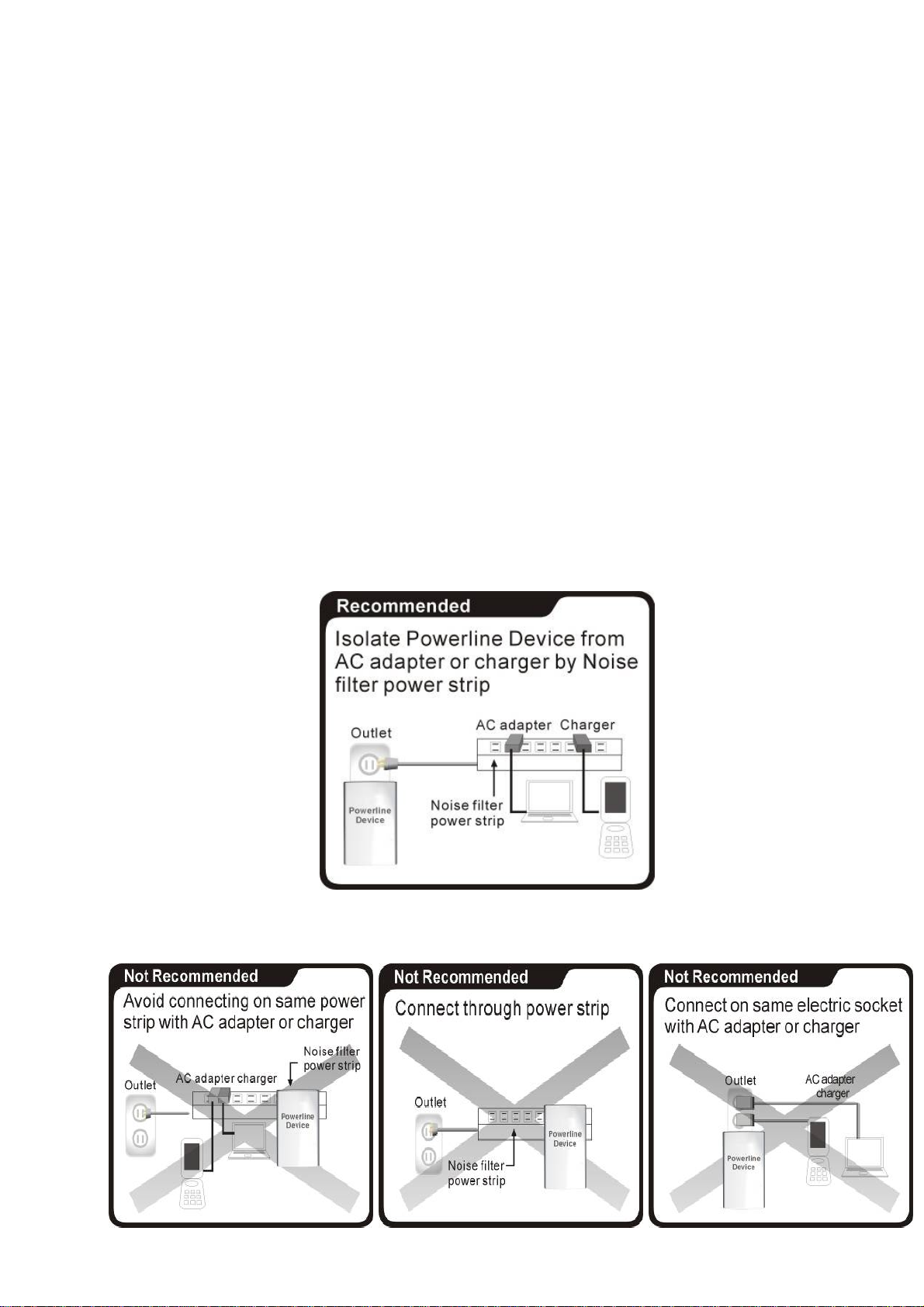
AC Outlets Connection
- Avoid connecting PLC device to an uninterruptible power supply (UPS) or backup power
supply device. For best results, connect the adaptors directly to a wall outlet is
recommended.
- Avoid connecting high-power consuming appliances to the same wall outlet.
See the following illustration:
For better performance, the following connection is recommended.
The following connections are NOT recommended.
31
Page 35

Connection via Power Strip
If user intends to connect the PLC device via power strip, please follow below reference for better
performance:
- Make sure the power strip does not support a noise filter or a surge protector.
Electrical Interference
Some household appliances may produce noise emission. If noise emission is spread over the
electrical wiring, it will affect PLC performance in the house. For the best results, we recommend to
connect an electrical noise filter with the appliances such as:
• Battery chargers (including cell phone chargers)
• Hair dryers
• Power drills
• Halogen light
• Vacuum cleaner
• Lights or lamps with touch-sensitivity feature supported
Electrical Wiring
The PLC device delivers data over the existing electrical wiring in the house. Actual PLC data
transfer rate might vary including the transmission distance between two PLC adapters.
Special Care for Business Installation
Due to several uncertainties that might degrade Powerline performance or block its operation, we DO
NOT recommend to install the Powerline devices into business environment. This device has NO
GUARANTEE to operate in a business environment such as offices or factories.
- The transmission distance between two Powerline devices is limited by the noise in the electrical
wiring.
- PLC communication is supported under the same power meter system. Business environment
might include more than one power meter systems and it will cause communication lost among
the Powerline devices.
32
Page 36

8. SPECIFICATIONS
Electric
AC Input 100 to 240V AC, 50/60Hz
Ethernet port N/A
Power connector Euro8 connector
Mounting Screw inlets (side, bottom), Tripod mounting thread
Camera
Sensor (1) 1/4 -inch CMOS VGA sensor, (2) brightness sensor
Up to 7 fps @ 640*480 in LAN
Resolution
Video compression MJPEG (Audio is not supported)
Lens
Eyeball Pan/Tilt Manual mode
Eyeball adjustment angle Pan: 0~ 270 degree, Tilt: 0 ~ 75 degree
IR distance 5 m (IR LED x 12)
IR mode Turns on under dark & being accessed
Video Setting
Security User-defined ID/Password protection, Public-key encryption
Networks
Network protocols TCP/IP, UPnP, DHCP client, Static IP, P2P
Board band router With DHCP and UPnP enabled
Up to 20 fps @ 320*240 in LAN
Up to 30 fps @ 160*120 in LAN
3.6mm, F2.0,
View angel 78 degrees
4 Glass w/ IR coating
Resolution, Brightness, Quality, Environment
Flip and Mirror setting
P2P - NAT traversal technology Proprietary UDP
PLC (Power Line Communication) Built-in 500 Mbps PLC adaptor
Max PLC Camera in a home 7 (w/ a PLC Ethernet adapter)
PLC standard HomePlug AV 1.1
PLC transmission distance Up to 300 m
PLC transmission security AES 128 bit
PLC freq. band 2 to 28 MHz, 30 to 50 MHz, 50 to 68 MHz
Mechanical and electronics
Work Temperature 0° C ~ 40° C
Storage Temperature -40° C ~ 60° C
Relative Humidity
Operating
Storage
: 10~85% Non-Condensing
: 5~90% Non-Condensing
33
 Loading...