

Page 1
0
Page 2

Table of Contents
TABLE OF CONTENTS .......................................................................................... 1
1. IMPORTANT INFORMATION ............................................................................ 2
S
AFETY PRECAUTIONS ............................................................................................ 2
2. INTRODUCTION ................................................................................................. 4
2.1
PACKING CONTENT .......................................................................................... 5
OVERVIEW ......................................................................................................... 5
2.2
3. INSTALLATION .................................................................................................... 7
4. TROUBLESHOOTING ....................................................................................... 16
5. SUPPORTED RESOLUTION ............................................................................ 17
6. AUDIO FORMATS SUPPORT ........................................................................... 18
7. PRODUCT SPECIFICATION ............................................................................ 19
1
Page 3
1. Important Information
Take time to read this user manual before you
use your BV-2500T and BV-2500R.
It contains important information and notes
regarding operating your wireless HD receiver
and transmitter.
The ZINWELL guarantee applies provided the
product is handled properly for intended use, in
accordance with its operating instruction, but
may not apply to the below cases:
z Repairs or product modification and
alterations have been executed by
unauthorized service personnel.
z Damages is caused by accidents including
but not limited to lighting, water, fire, or
moisture.
z Do not use provided power adapter with
specific power rating not compliant in the
attached label of power adapter.
The model number on the product has
z
been altered, deleted, removed or made
illegible.
Safety Precautions
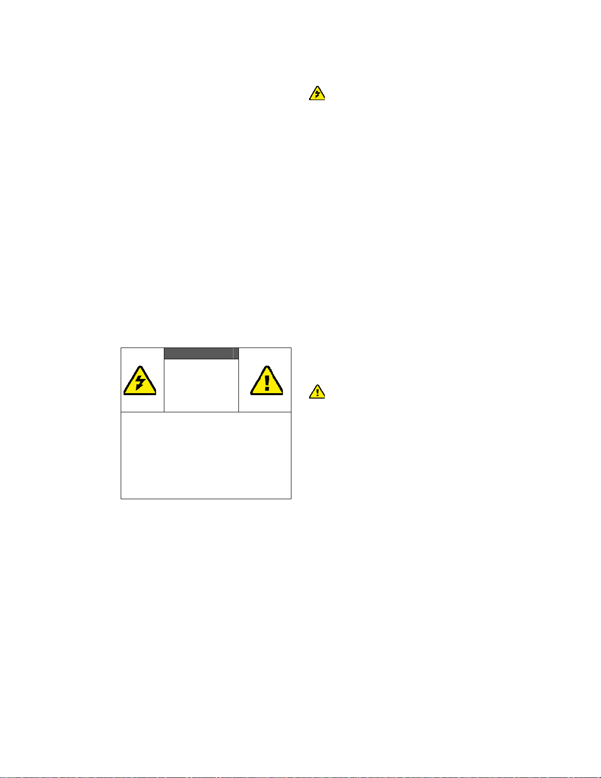
TO REDUCE THE RISK OF ELECTRICAL
DO NOT REMOVE THE COVER
NO USER-SERVICEABLE PARTS ARE
REFER SERVICING TO QUALIFIED
WARNIN G!
RISK OF
ELECTRICAL
SHOCK
DO NOT OPEN
WARMIN G:
SHOCK
INSIDE
PERSONNEL
Danger: Be careful with electricity.
z Power to the units must be switched off
before any work is undertaken, such as
any AV device connection or TV
connection.
z Power ou t let: To prevent electric shock,
be sure the electrical plug used on the
receiver’s and transmitter’s power cord
matches the electrical outlet used to
supply power to the receiver/transmitter.
z Power cord: Be sure the power cord is
routed so that it will not be stepped on or
pinched by heavy items.
z Power overloading: Avoid overloading
electrical outlets or extension cords
which otherwise could result in electric
shock or fire.
z Lightning: For protection from lightning
or when the receiver/transmitter is left
unattended for a long period, disconnect it
from the power source.
z Always disconnect the power cord from
the power outlet when you are not using
your wireless HD receiver and transmitter.
This reduces your risk of electric shocks
or fire.
Warnin g
z This product should not be exposed to
dripping or splashing. No object filled with
liquids, such as vases, should be placed on
the product.
z Object Entry: To avoid electric shock,
never stick anything in the slots on the
case or remove the cover.
z Place receiver/transmitter on a flat. Hard
and stable surface.
2
Page 4

Y
z Ventilation: Do not block the ventilation
slots on the receiver/transmitter or place
any heavy object on top of it.
Blocking the air flow could damage the
receiver. Arrange components so that air
can flow freely around the receiver.
Ensure that there is adequate ventilation if
the receiver is placed in a stand.
Put the receiver/transmitter in a property
ventilated area, away from direct sunlight
or any source of heat.
z Wat er E xposure: To reduce the risk of
fire or electric shock, do not expose the
receiver/transmitter to rain or moisture.
DECLARATION OF CONFORMIT
This device complies with Part 15 of the FCC
Rules. Operation is subject to the following
two conditions:
(1) This device may not cause harmful
interference, and
(2) This device must accept any interference
received, including interference that may
cause undesired operation.
EMI (Electro Magnetic Interference)
tested.
EN 55022 Information technology
equipment----
Radio disturbance characteristics--- Limits
and methods of measurement
EN 61000-3-2 Electromagnetic
compatibility (EMC)---
Part 3-2:Limits---Limits for harmonic current
emissions(equipment input current up to and
including 16 A per phase)
EN 61000-3-3 Electromagnetic
compatibility (EMC)---
Part 3:Limits---Section 3: Limitation of
voltage changes, voltage fluctuations and
flicker in public low-voltage supply systems,
for equipment with rated current ≦16 A per
phase and not subject to conditional
connection
EN 55024 Information technology
equipment----
Equipment---Immunity
characteristics---Limits and methods of
measurement
EN 301 489-1
Electromagnetic compatibility and Radio
spectrum Matters (ERM); Electro Magnetic
Compatibility (EMC) standard for radio
equipment and services;
Part 1: Common technical requirements
EN 301 489-17
Electromagnetic compatibility and Radio
spectrum Matters (ERM); Electro magnetic
Compatibility(EMC) standard for radio
equipment;
Part 17: Specific conditions for 2,4 GHz
wideband transmission systems, 5GHz high
performance RLAN equipment and 5,8 GHz
Broadband Transmitting Systems
EN 60065 Audio,video and similar
electronic apparatus—Safety requirements
TRADEMARK INFORMATION
z HDMI, the HDMI Logo and
High-Definition Multimedia Interface
are trademarks of HDMI Licensing
LLC.
Special Notice
z Never use this product nearby an aircraft
or medical facility. It will cause an
interference and wrong effect on the
operation.
z Never use this product in the following
location where wireless wave will cause
the abnormal video and audio (noise,
blocked image...etc,).
¾ Installed in the walls that its used
material is hard accessible.
¾ This device should be situated away
from the refrigerator or metal
fitment.
¾ Crowded place
z This product has been tested and
manufactured to comply with each
3
Page 5
country’s safety rules. However, there is
no guarantee that interference will not
occur in a few particular installation. If the
interference is happened, increase the
separation distance between the
transmitter and receiver.
z BV-2500 is susceptible to interference
from 5GHz wireless device, such as router
or other wireless device. For example, if
you have an 802.11n router, configure it to
use the 2.4 GHz band rather than the
5GHz band.
z Optimal Range between BV-2500
transmitter and receiver is between 1
meter and 30 meters within line of sight.
2. Introduction
BV-2500T and BV-2500R wireless video
transmission solution allows users to place your
HDTV set or projector where you want- just
connect your HDTV set and BV-2500R by HDMI
cable. Any display like LCD, PDP or computer
monitor with HDMI input connector
applicable to our BV-2500R.
Connect the BV-2500T to your multiple
High-Definition devices such as Cable/Satellite
Box, HD Set-Top Box, Blu-Ray DVD Player, Game
Console, and Media Center PC hidden in your
cabinet behind your seating area. It reserves
clean space around the perimeter of your TV set
in your living room and solves the cluttered
cables connection problem. You may also place
the transmitter BV-2500T and source AV
component near HDTV set.
This solution delivers uncompressed 1080P
@24/30 Hz True Cinema video content to your
existing HDTV set wirelessly. It operates the
transmission in 4.9 GHz~ 5.9 GHz frequencies
that can adjust its frequency automatically in case
of interference with another RF system. With
built-in Omni-directional antennas, it can
transmit uncompressed video content over 20
meters (LOS: Line of sight) whole-room range
with no latency.
Provided IR Sensor Extender Cable and IR
Blaster Extender Cable in the package allows
users to point the existing remote control of
are
source components at BV-2500R directly for
device operation. (These devices with
Transmitter connection may be placed in a
closet or separate room.)
4
Page 6
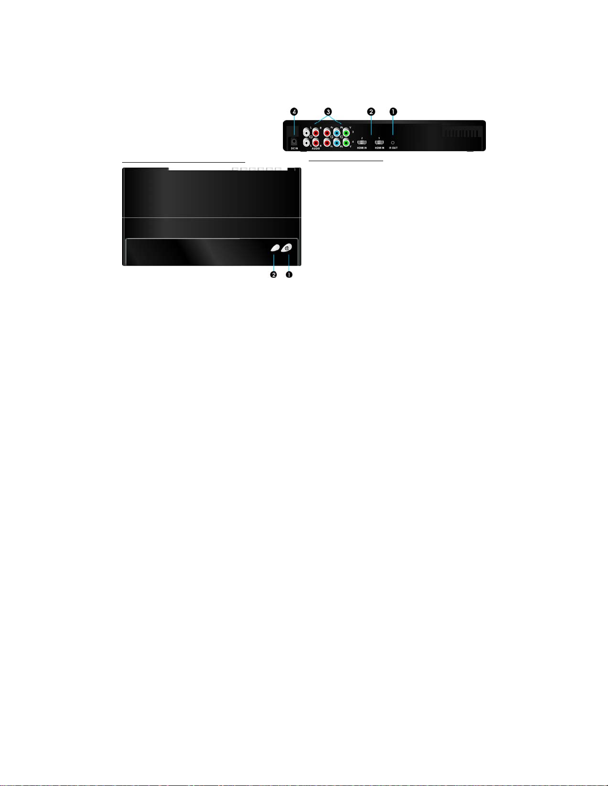
2.1 Packing Content
Please check whether the following items are
present in the package. If any items missed or
damaged, please call your dealer.
2.2 Overview
A. BV-2500T: FREEline HD
transmitter
Front Panel Buttons and LEDs
X Power Button with LED indicator
Press to turn the transmitter on and off. The
indicator in the Power button is lit solid blue
when the power is on, and turns red in standby
mode.
Y Source Selection Button
Press to switch between the various inputs of
the transmitter. The one of four LED indicators
next to this button is lit solid blue to show
current input you switch. Press this button to
cycle through connected sources in sequence.
Note:
(1) Make sure you have connected the
BV-2500R correctly to your HDTV set by
HDMI cable, and have selected the correct
HDMI input on your TV.
(2) You can also press the TRANSMITTER
POWER button to turn the box on.
Main unit backside
X IR Blaster Extender Jack
Plug the IR Blaster Extender Cable into the IR
OUT jack at rear panel of the transmitter.
Attach the IR blaster to the device connected to
the BV-2500T. You can point the device’s existing
remote at the BV-2500R receiver to control
connected device.
Y HDMI IN
Connect Transmitter to High-definition video
devices that have an HDMI port using a provided
HDMI cable.
Z Component Video IN/ Audio L/R IN
Connect to devices with Component jack
(YPbPr) and Audio L/R, such as DVD player,
Blu-Ray Player or Cable Set-Top Box.
[ DC IN
For connecting the BV-2500T power adapter.
Note: The BV-2500T transmitter can support
two devices running on HDMI cable and another
two running on YPbPr component video signals
at the same time. Only one AV source from
BV-2500T can be selected and displayed in the
HDTV set once Transmitter is paired successfully
with receiver.
5
Page 7
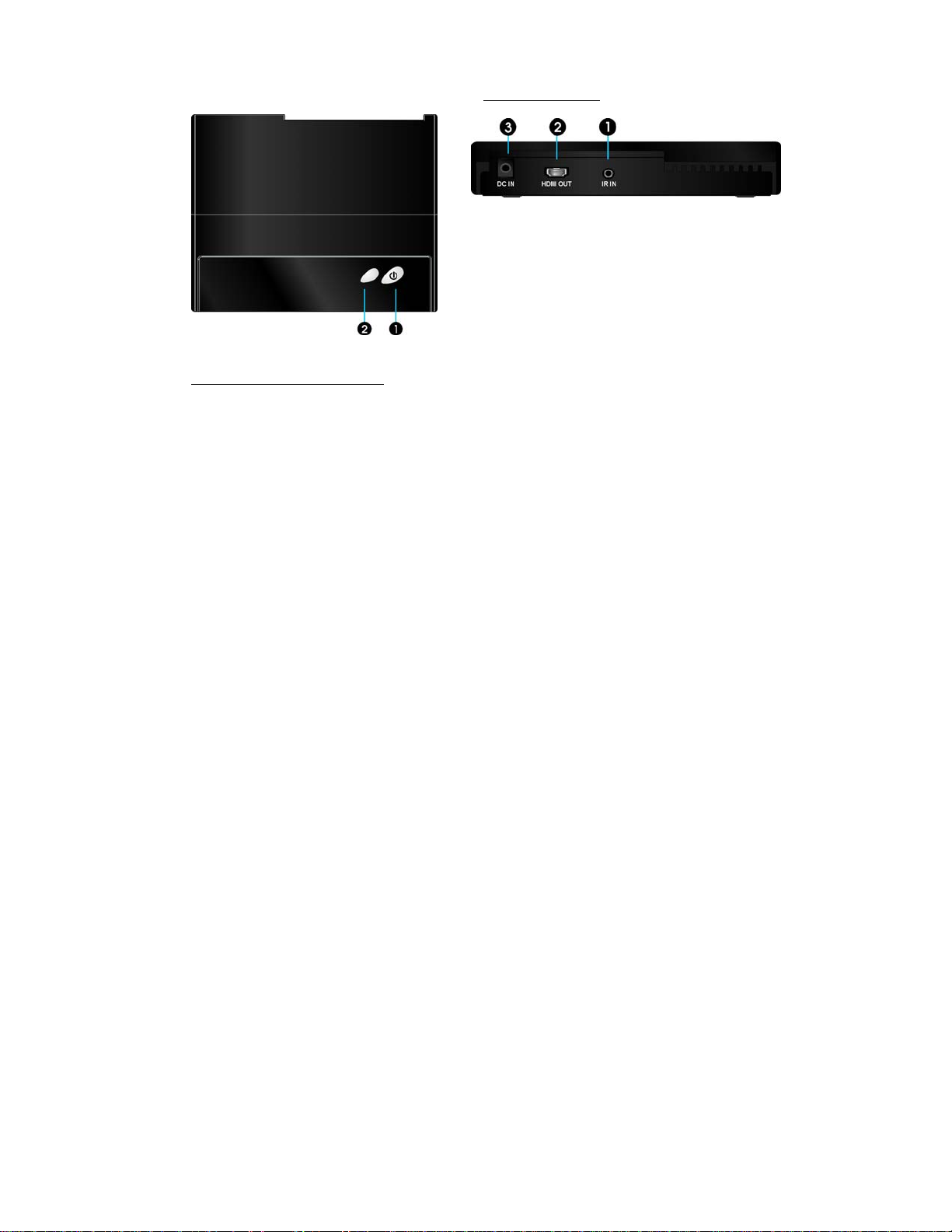
B. BV-2500R: FREEline HD receiver Main unit backside
X IR Sensor Extender Jack
Plug the IR Sensor Extender cable into the IR IN
jack at the rear panel of the receiver.
sensors with cable are placed near your HDTV
set so that you can easily receive and relay the IR
Front Panel Buttons and LEDs
X Power Button with LED indicator
Press to turn the receiver on and off. The
indicator in the Power button lights up in blue
when the power is on, and turns red in standby
mode. The signal quality indicator next to the
Power button shows the receiving signal quality
from transmitter.
Y Source Selection Button
Press this button repeatedly until you see the
desired transmitting video on your TV set from
your High-Definition device.
command for external device connected with
BV-2500T.
Y HDMI OUT
Connect a HDMI cable. The other end connects
to the HDTV set.
Z DC IN
For connecting the BV-2500R power adapter.
Generally,
6
Page 8
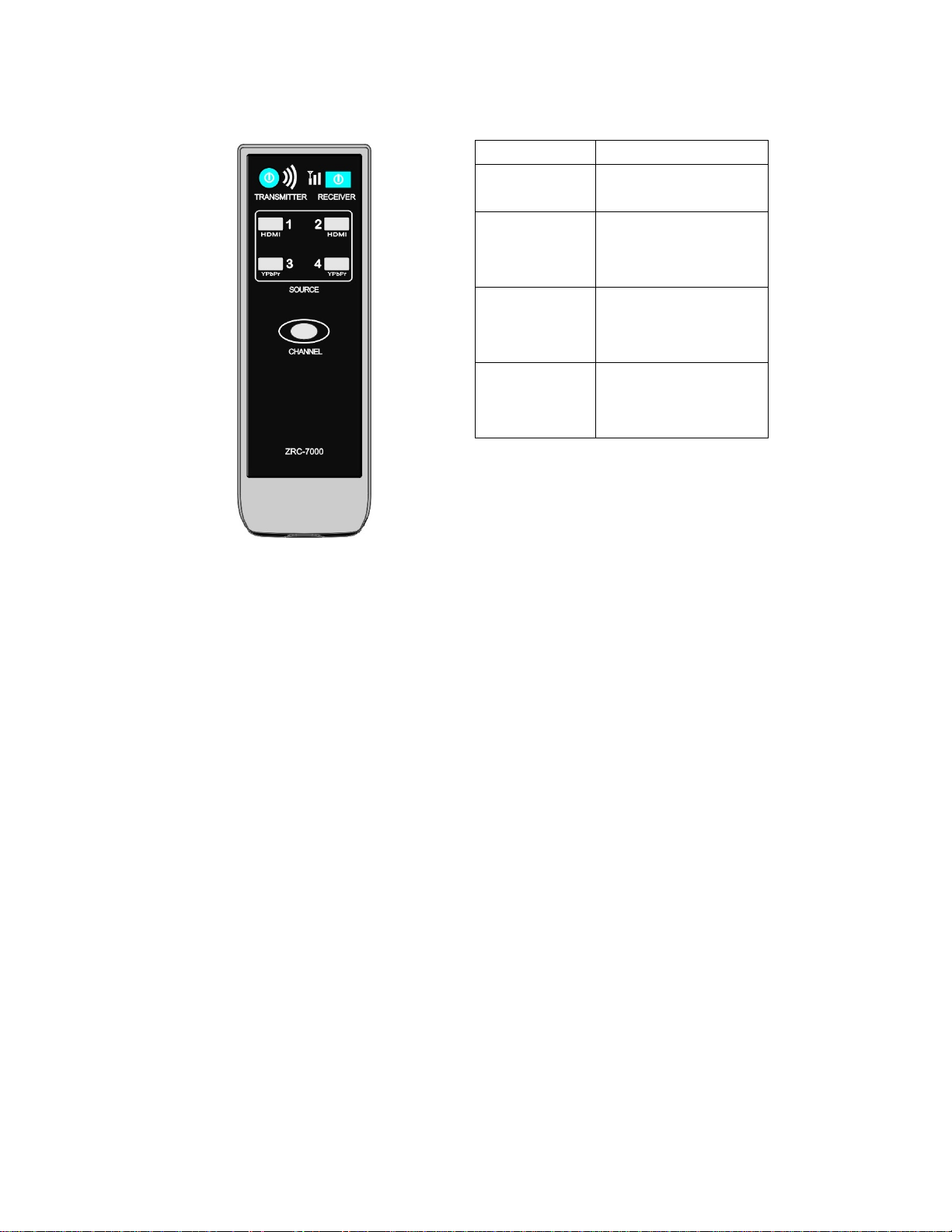
C. Remote Controller Instruction
Button Function Description
TRANSMITTER/
RECEIVER power
CHANNEL Press to change another
HDMI 1/2 Press this button to switch
YPbPr 3/4 Press this button to switch
Press to turn the BV-2500
transmitter on/off.
wireless channel manually if
you experience video
noise.
the video source from the
connected HDMI device
source.
the video source from the
connected YPbPr device
source.
7
Page 9
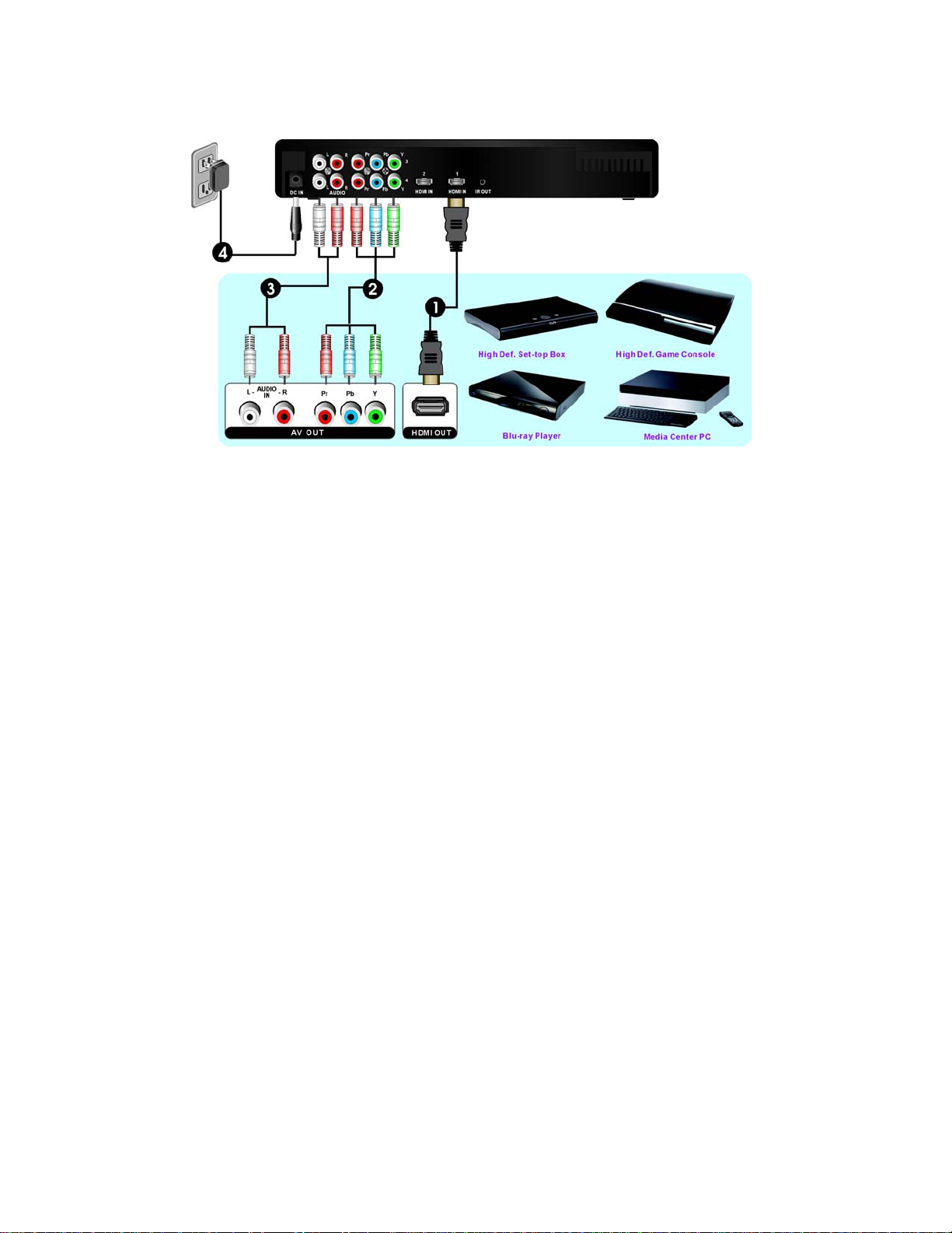
3. Installation
Step1: Multiple Devices Connection
with BV-2500T:
(1) Connect the BV-2500 TRANSMITTER’s
“HDMI IN” to the High-Definition device’s
“HDMI OUT” by HDMI cable (included).
The BV-2500 has two HDMI inputs for
newest High-Definition devices connection,
like PS3, Blu-ray Player.
(2) Connect a set of RCA cables (green, blue,
red-colored cables) between the Y/Pb/Pr IN
connectors of the BV-2500T and
corresponding COMPONENT (Y/Pb/Pr
OUT) connectors on your High-Definition
devices.
(3) Use Audio Cables to connect between the
“AUDIO L/R IN” connectors of the
BV-2500T and the corresponding “AUDIO
L/R OUT” connectors on your
High-Definition devices. (AUDIO L
connection cable is the one with white
color and AUDIO R connection cable is the
one with red color.)
Note: Transmitter has 4 source inputs which
means you can have 4 choices for video sources
such as DVD, cable STB, PS3 and media center.
Only one source can be selected and played, so
you need to cycle transmitter to the one desired
video source.
(4) Connect the supplied power adapter
between the DC IN jack of the BV-2500T
and a mains socket. The LED indicator in
the POWER button lights up in solid red
when the BV-2500T is connected to the
power mains .
Note: The AV components are not
included in BV-2500 package.
8
Page 10
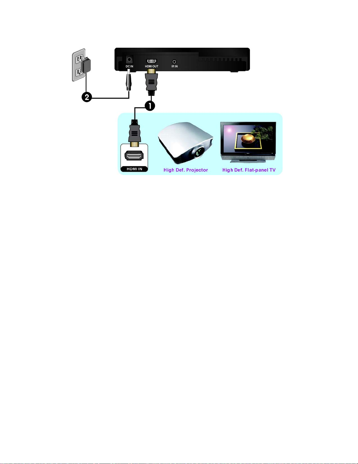
Step2: HDTV set Connection with
BV-2500R:
(1) Connect the HDMI cable between the
HDMI OUT jack of the BV-2500R and your
HDTV set.
Press the SOURCE/INPUT button on
your TV’s remote to select “HDMI” video
mode.
(2) Attach one side of the provided Velcro
(fastening tapes) to the receiver back cover.
Then use Velcro of another side to attach
the receiver directly to the wall next to the
HDTV set.
(3) Connect the supplied power adapter
between the DC IN jack of the BV-2500R
and a mains socket.
9
Page 11
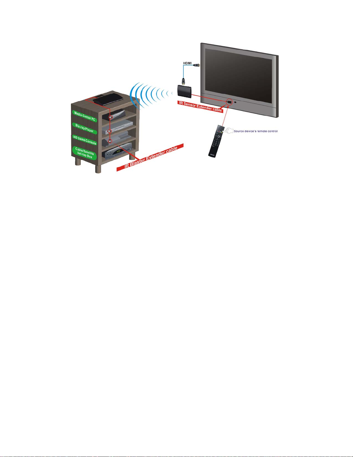
Step3: If necessary, connect the
Infrared (IR) Blaster & Sensor. Users
can point hand-held remote control of
your High Definition device at
BV-2500R or HDTV set directly for
source device’s operation at
Line-of-sight (20 meters transmission
distance).
(1) Plug the IR Blaster cable into the IR
OUT jack of the BV-2500T.
Place the IR blaster head in the IR senor
of your High-Definition video devices
nearby.
The infrared (IR) sensor is on the front of
your High Definition device, usually
behind a dark, sometimes reddish plastic
window.
When the IR blaster cable is connected, it
relays infrared command from your
remote to the various device components.
Users can control AV device with
transmitter connection using existing
remote control directly.
(2) If your connected device will be out of the
direct line of sight of your remote
controls, plug the IR Sensor Extender
cable into the IR IN jack at the rear panel
of the receiver.
Note:
(1) The remote control of BV-2500 can only
switch between inputs of BV-2500. It does
not switch the inputs of your HDTV set or
projector.
(2) IR blaster only supports 38K (NEC) and
36K (RC5, RC6) remote’s signal protocol.
Some device may not be supported.
10
Page 12
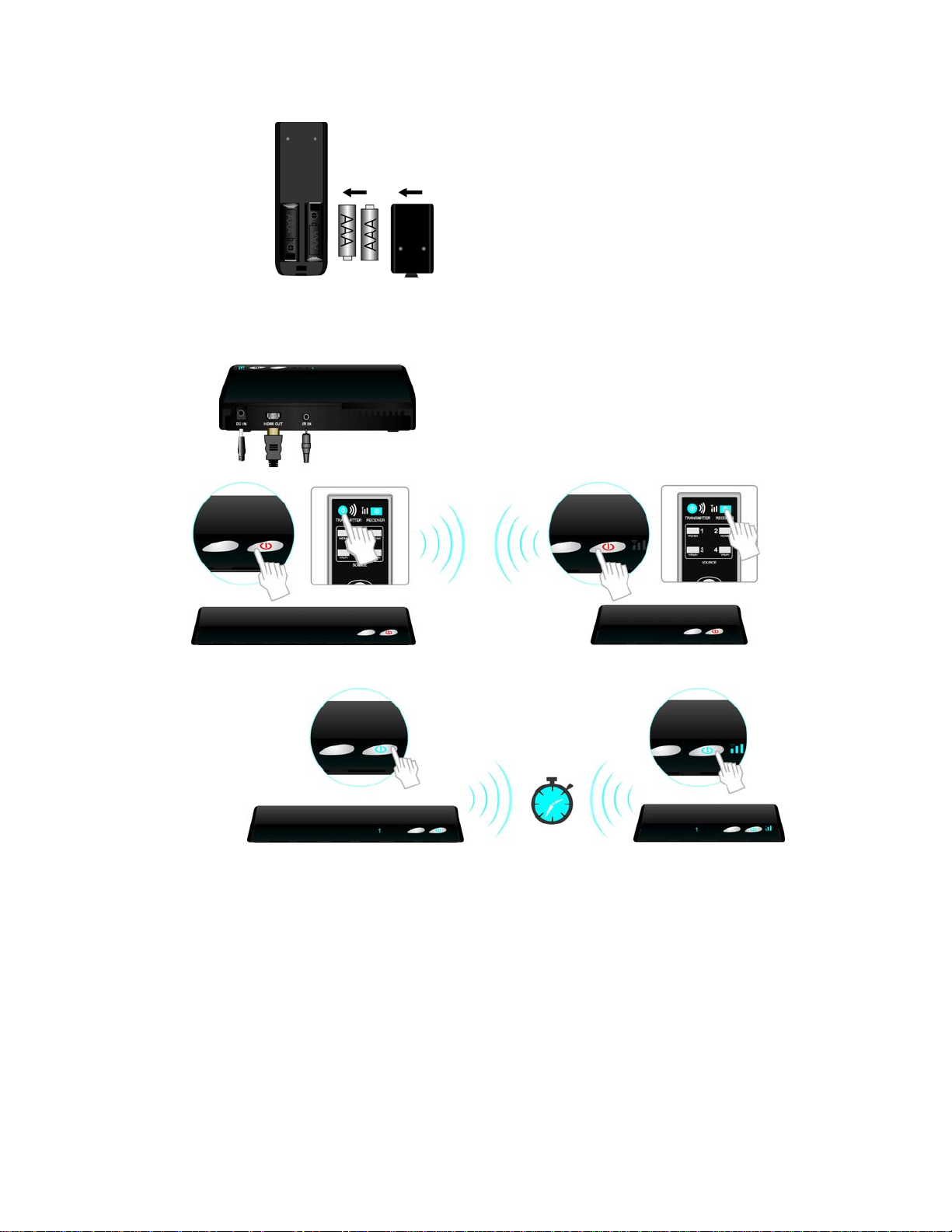
Step 4: Power on your BV-2500T and BV-2500R
(1) Place the two AAA batteries into the remote control.
(2) If users already plugged the power cord, the power or BV-2500 will be turned on automatically.
If it’s under Standby mode (The POWER LED shows red), press the TRANSMITTER and
RECEIVER POWER button to turn on the BV-2500T and BV-2500R.
(3) During warm-up, the POWER LED will blink blue until the signal link between BV-2500T and
BV-2500R is established.
11
Page 13
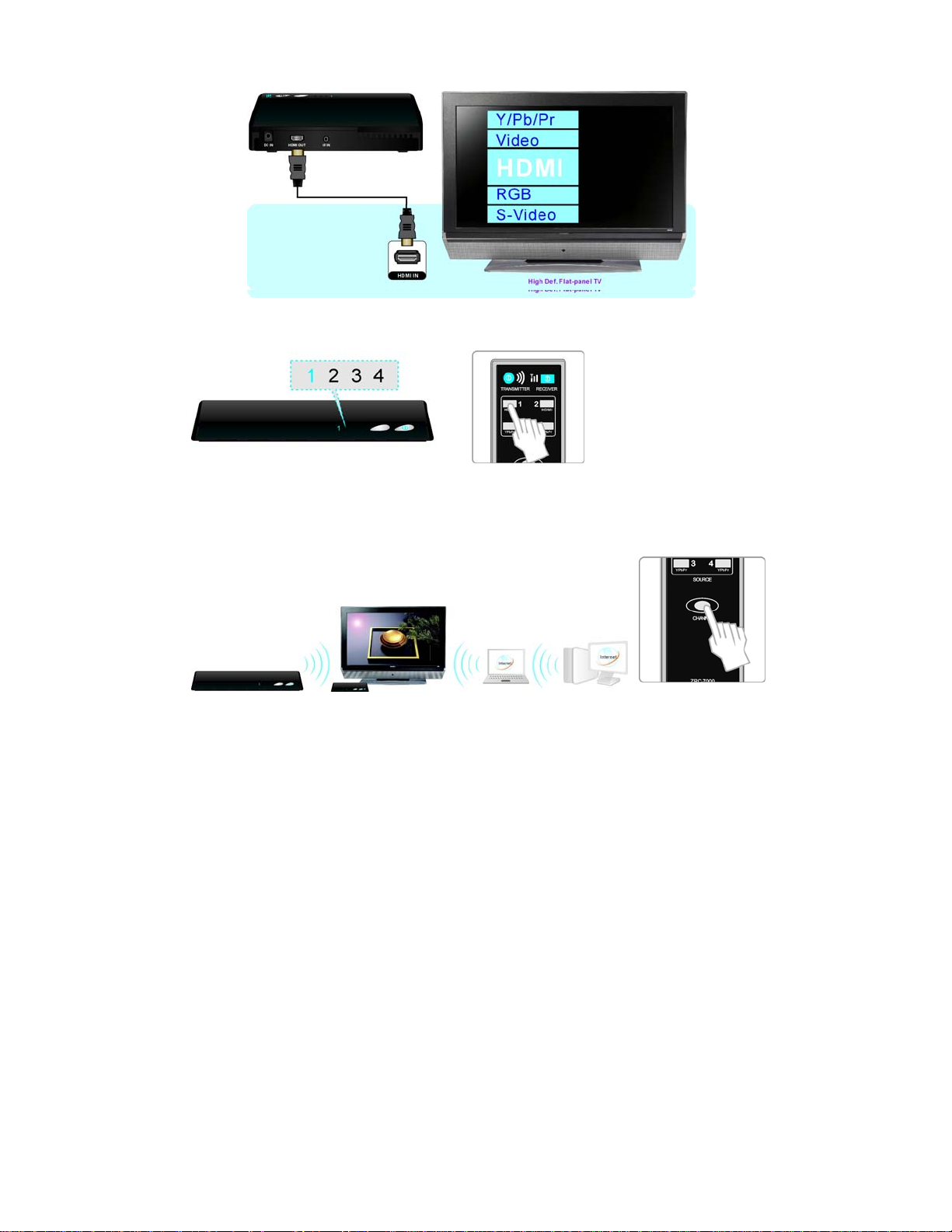
(4) Ensure your LCD TV set or projector is set to HDMI input mode and already powered on.
(5) Press the Source 1HDMI 2HDMI 3YPbPr 4YPbPr button, until you see the available video
from your device.
(6) If you have some electronic devices like cordless phone, wireless access point/ router used with
5GHz channel frequency near the BV-2500, you may experience no/noise picture or diminished
sound quality. Press the CHANNEL button three seconds to adjust to an appropriate channel for
BV-2500.
12
Page 14
r
Note:
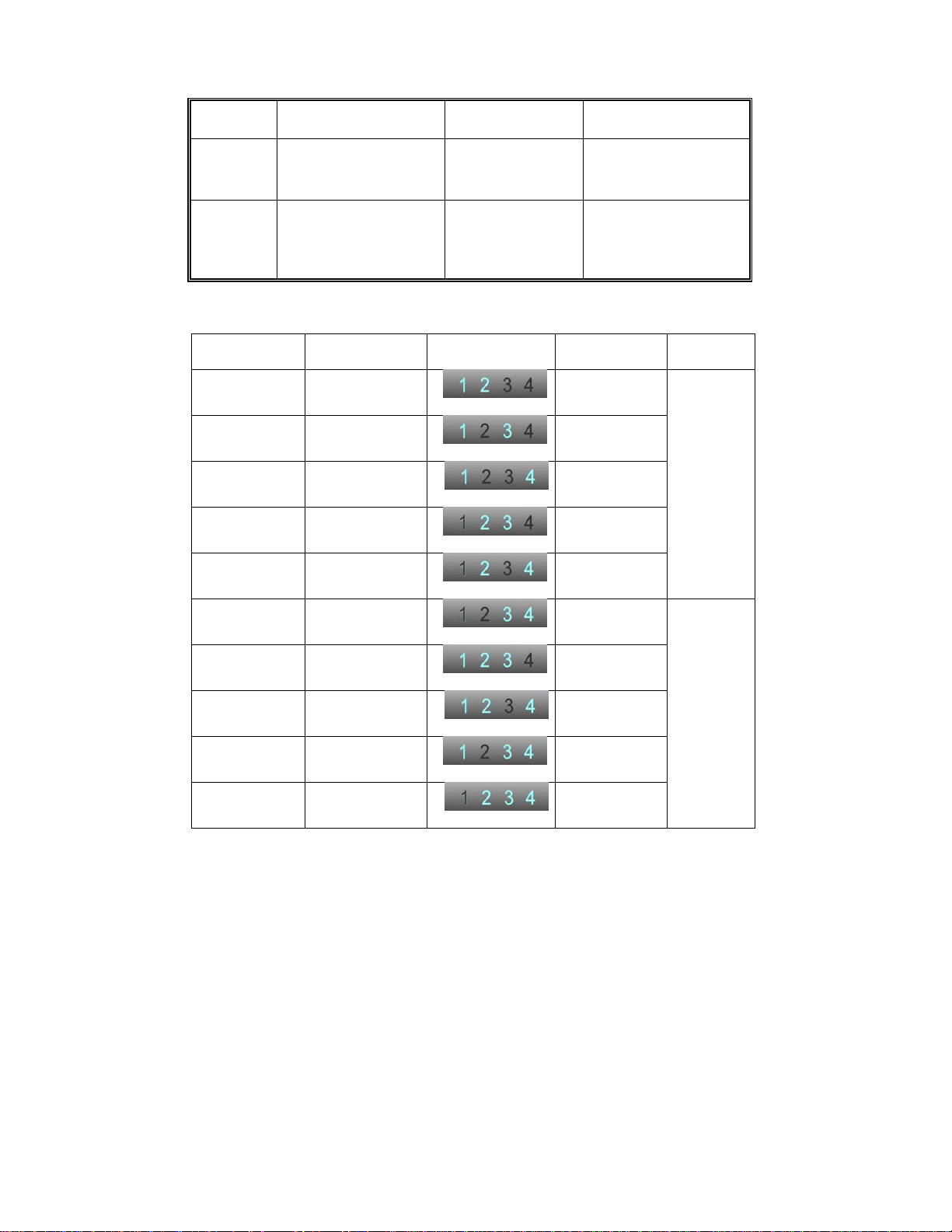
A. How to change to a different wireless channel for BV-2500:
Method
LED indicator
status
B. LED indictor detail overview for the Wireless Channel:
RF Channel; Frequency (MHz) LED status
1. Enter wireless RF channel
adjustment mode
Press the CHANNEL
button three seconds.
The all SOURCE LED 1-4
will blink 3 times to show
the current RF channel.
# 32 5160
# 36 5180
# 40 5200
# 44 5220
2. Changes to the next
RF wireless channel
Press the CHANNEL
button again.
The SOURCE LED will
automatic show the
current switched RF
channel.
3. Exit the wireless RF
channel adjustment mode
There is no button on the
remote pressed about 10
seconds,
Show the current input
source.
LED blinking
numbe
Area
Europe &
12
13
14
23
USA
# 48 5240
#149 5745
#153 5765
#157 5785
#161 5805
#165 5825
24
34
123
124
134
234
13
USA
Page 15

(7) If all the operation is normal, the POWER, SOURCE LED will glow solid blue and Signal Quality
will light in blue with 3 signal quality. Please refer the next LED details part:
14
Page 16

g
.
w
Note:
A. Make sure your multiple High-Definition devices connected with BV-2500T have already
powered on.
B. Warming-up or source switching time should be approximately 15~20 seconds during the
normal operation.
C. BV-2500 remote control will not control your A/V components’ operation.
D. Video from the YPbPr component source device appears but dim, press the 3/4 YPbPr button
repeatedly on the remote control to fine-tune the picture performance.
TRANSMITTER/RECEIVER LED indicator light details:
LED indicator status light on the front that indicates what’s happening..
Note:
A. The Quality LED indicator shows whether a connection is active with the transmitter side.
During the normal operation, the Quality LED indicator will light in blue with 3 signal quality. If
POWER
LED
Solid Red Off Standby
Solid Red Off
Blinking Blue
Solid Blue
there is no signal quality and blinking blue in Source & Status LED, the transmitter are most
likely out of range. You may verify the range and adjust the distance closer between transmitter
and your HDTV set with receiver. (The maximum video transmission range is 20 meters at line
of sight (LOS) scenarios.)
B. It’s normal to see the Source LED blinking when you switch your AV sources.
C. If disconnection or lost link occurs, it maybe due to the following reason:
a. If the range is over the maximum transmission distance.
b. Either transmitter or receiver has been switched off.
D. If the SOURCE LED continues to blink blue (slower than no signal mode) and there is
no/abnormal video displayed, this is an indication that video format from your A/V source device
Source LED Mode Status
In standby mode
HDMI
connection
in Hot Plug
status.
Blinking
Blinking 3 times
per second
(Quickly)
Blinking 1 times
per second
(Slowly)
Solid blue
In wireless
Linking
On Mode
TV & Receiver are both powered on, and then
remove HDMI cable connection from receiver.
After 1 minute, the receiver will automatically enter
the standby mode which POWER LED stops
blinking and turns solid red.
Warning up in progress or interrupted RF
connection.
Input from selected source device is not detected.
Unrecognized video format.
(Not support or out of range.)
Reco
ith stable RF signal.
nized video format
Transmission is available
15
Page 17

•
r
w
is not supported or out of range.
4. Troubleshooting
Problem Solution
The BV-2500 front panel
power indicator (red LED)
doesn't light up.
There is no video is displayed
on your TV screen.
Poor picture quality or
intermittent video play.
• Check that the power plug of BV-2500T/BV-2500R is
properly inserted into a functioning power outlet.
• Verify that the proper cable has been selected and
installed between the desired transmitter input connector
and your High-Definition device.
• On your TV side, select the HDMI source you connected
to BV-2500R.
• Verify the POWER LED and SOURCE LED indicator of
BV-2500.
Flashing blue power LED
* Ensure the transmission range between transmitter and
receiver is not over 20 meters (LOS-Line of sight)
transmission distance. Move the transmitter closer to the
receiver.
* Press CHANNEL on the remote control to change
wireless channel manually.
Solid blue POWER LED + slow and flashing
SOURCE LED
* Ensure your video format is recognized/ supported and
within the format range.
*Connect the source device to your TV to check and modify
the video format compatibility.
Solid blue POWER LED + quick and flashing
SOURCE LED
* Ensure the proper cables are connected between
transmitter and your devices.
* Ensure your HD devices connected with the BV-2500
transmitter are powered on.
• Press the 1HDMI 2HDMI 3YPbPr 4YPbPr button in
the RCU to search the available video source.
• Check your video resolution with HDMI input from your
device is 1080p @ 24/30 Hz, 1080i, 720p, 576p, 480p.
Check your video
device is 1080p @ 24/30 Hz, 1080i, 720p, 576p, 480p.
Please refer to the Supported Resolution chapter that it
define video consumer timing of your HD device BV-2500
supports.
• BV-2500 does not support 1080p/50 or 60Hz video
format.
esolution
ith HDMI input from your
16
Page 18
•
•
No audio.
Press CHANNEL
wireless channel manually.
• Ensure transmission distance is not over 20 meters (LOS).
Check your TV’s volume is
"MUTE" mode.
• Check that the audio connectors are properly connected.
• Ensure the format of audio from the source device we can
support. Please refer the details in Chapter 6 Audio
Formats support.
on the remote control to change
properly set and not in
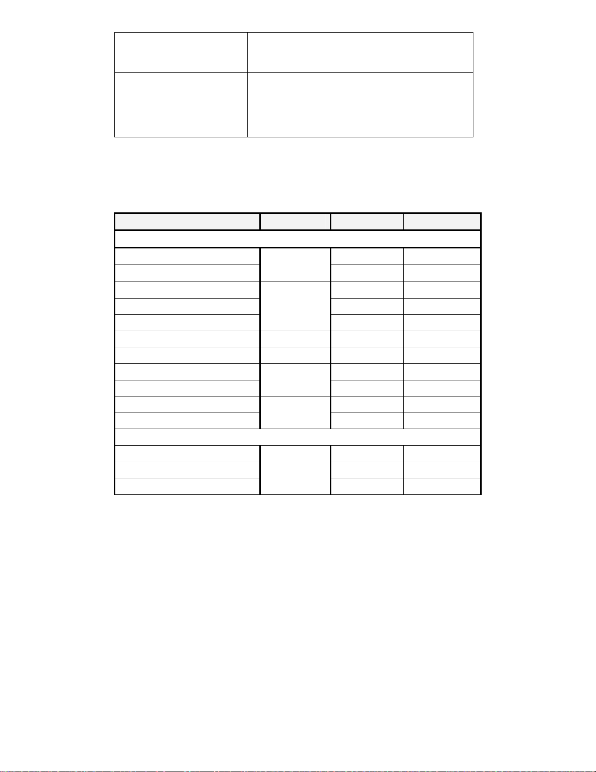
5. Supported Resolution
If the SOURCE LED continues to blink blue (slower than no signal mode) and there is
no/abnormal video displayed, this is an indication that video format from your A/V source
device is not supported. Ensure that the consumer timing of your HD device is compliant
with below detail sheet.
Video Format Timings Format Name HDMI in Component in
Primary CEA Video Timing
720(1440)x480i @ 59.94Hz
720(1440)x480i @ 60Hz n/a n/a
640x480p @ 59.94/60Hz
720x480p @ 59.94Hz YES YES
720x480p @ 60Hz YES n/a
720(1440)x576i @ 50Hz 576i n/a YES
720x576p @ 50Hz 576p YES YES
1280x720p @ 50Hz
1280x720p @ 59.94/60Hz YES YES
1920x1080i @ 50Hz
1920x1080i @ 59.94/60Hz YES YES
Secondary CEA Video Timi ng
1920x1080p @ 23.98/24Hz
1920x1080p @ 25Hz YES YES
1920x1080p @ 29.97/30Hz YES YES
480i
480p
720p
1080i
1080p
n/a YES
YES n/a
YES YES
YES YES
YES YES
17
Page 19
YES
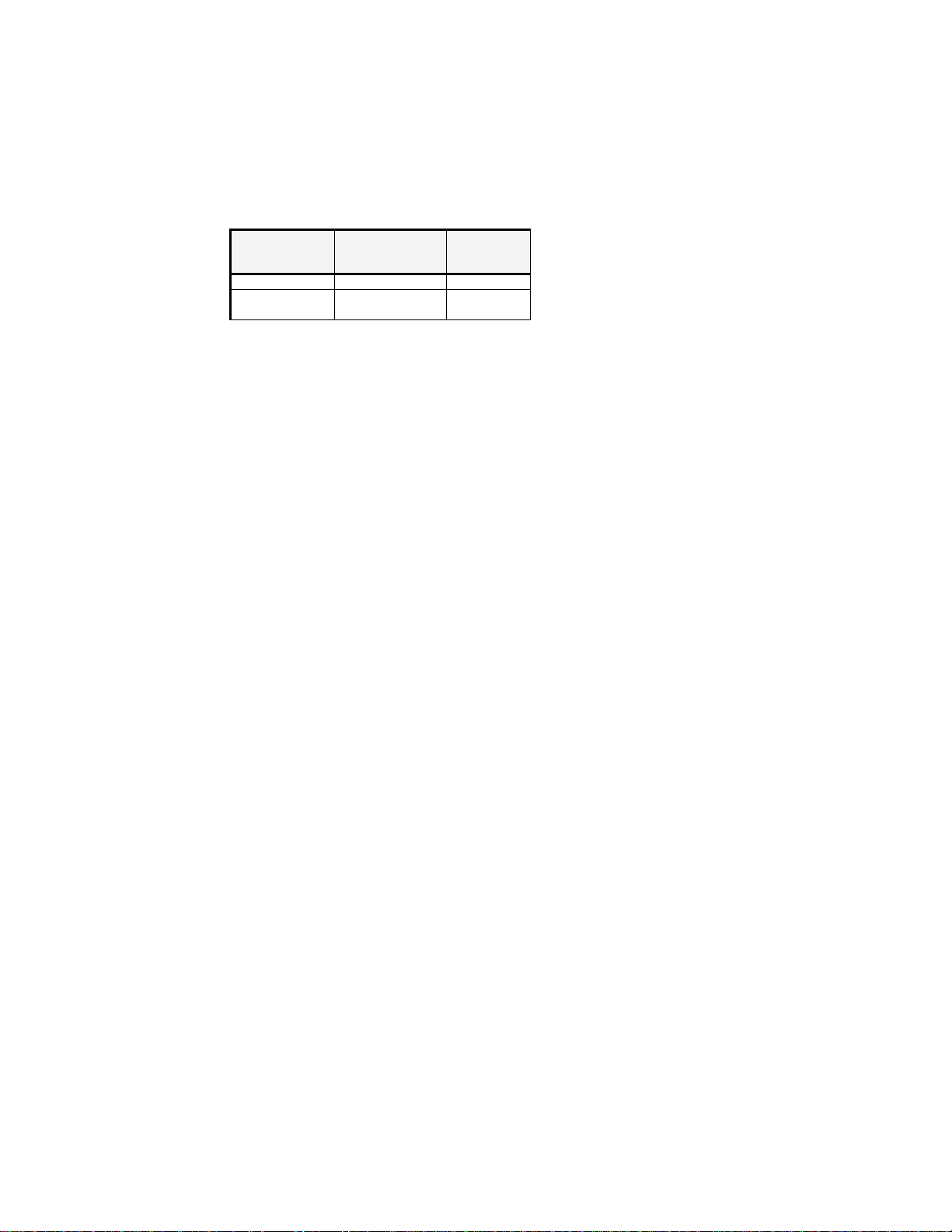
6. Audio Formats Support
Analog Audio from Base Band audio L/ R inputs: Convert to 2-channel by fixed 24
bits/sample with sampling rate 48KHz by I
Interface transmission
Digital Audio from HDMI inputs: Support up to 3.072Mbit/s
16~ 24 bits/sample with sampling rate 32~ 48KHz 2 channels PCM by
I2S bus.
2
channels
PCM
16 bits YES
24 bits YES YES
channels 16~ 24 bits/sample with sampling rate 32~ 96KHz by S/P DIF
bus over Wireless High-Definition Interface transmission. Support
Dolby Digital, Dolby Digital EX, Dolby Digital Surround EX.
44.1KHz 48KHz
2
S bus over Wireless High-Definition
2 to 8
18
Page 20
-
r
YES
YES
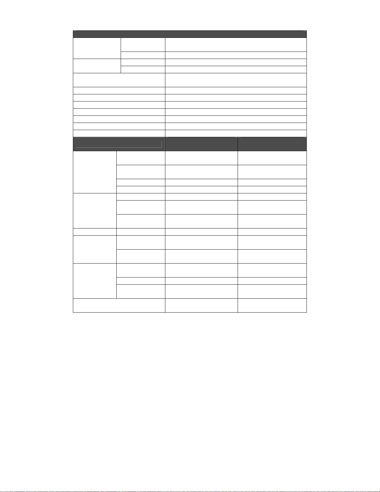
7. Product Specification
General Specifications
Supported Video
Resolution
Supported Audio
Formats
Transmission Distance
System Latency No latency (<1ms)
Antenna High Performance Internal Antennas
Operating Frequencies 4.9~ 5.9GHz (non-DFS Frequency Bands) for US, EU, JP, TW
Supported IR Blasting Frequency 36 KHz/ 38 KHz
Power Supply 100~ 240V AC in, 5V 3A DC out Power Adaptor
Operating Temperature 0~40°C
Regulations FCC, CE
A/V Interfaces
Control Signal
Interfaces
Power Interface Power Input 5V DC Jack
Switches
LEDs
Dimensions
Component
Input
HDMI Input 1080p/@ 24/30 Hz, 1080i, 720p, 576p, 480p
Analog Audio
Digital Audio
Interfaces
Component Input
Analog Audio L/ R
Input
HDMI Input Two (Type A)
HDMI Output IR Senso
IR Sensor
Extender
IR Blaster
Extender
Front Power
Switch
Source Selection
Switch
Status LED
Source LED 4 x Blue LEDs
Signal Quality
Status
1080p @ 24/30 Hz, 1080i, 720p, 576p, 576i, 480p, 480i
48KHz and 24-bit Per Sample
up to 3.072 Mbps AC-3 and DTS
The maximum video transmission range is 20 meters line of
sight (LOS) scenarios.
BV-2500T
Tw o S e t s o f R C A
Connectors
Tw o S e t s o f R C A
Connectors
- 2.5mm Jack
2.5mm Jack -
YES (One Tack Switch) YES (One Tack Switch)
YES (One Tack Switch) YES (One Tack Switch)
1 x LED (Two Tone: Blue&
Red)
- 3 x LEDs
295(W)x 149(L)x 45.5(H)
mm
-
-
One (Type A)
5V DC Jack
1 x LED (Two Tone: Blue&
Red)
4 x Blue LEDs
180(W)x 140(L)x 39(H)
mm
BV-2500R
19
 Loading...