

Page 1
STANDALONE INTERFACES
USB & ETHERNET-DMX
1024 CHANNELS
V.1.0
Page 2

Datasheet – Standalone Interfaces USB & Ethernet - DMX 1024 channels 2
SUMMARY
Hardware technical specifications .................................................................................................................................................................................. 4
Front Face of the Ethernet interface .............................................................................................................................................................................. 5
Side Faces of the Ethernet interface .............................................................................................................................................................................. 5
Top Face of the Ethernet interface ................................................................................................................................................................................. 6
Interface buttons and display features ......................................................................................................................................................................... 7
Ethernet connection .......................................................................................................................................................................................................... 10
RESETTING THE IP ADDRESS .................................................................................................................................................................................... 11
IP configuration from software ................................................................................................................................................................................ 11
Installation diagram ...................................................................................................................................................................................................... 12
Internal clock setting ........................................................................................................................................................................................................ 13
Zone Mode ........................................................................................................................................................................................................................... 14
Zone configuration in the software ........................................................................................................................................................................ 14
Standalone Interface Triggers ....................................................................................................................................................................................... 16
Switch to Standalone mode ...................................................................................................................................................................................... 16
Interface Mode settings .............................................................................................................................................................................................. 16
LED buttons trigger ...................................................................................................................................................................................................... 19
Contact wiring and connections with RJ45 Pins................................................................................................................................................ 20
Triggering commands ................................................................................................................................................................................................. 22
IR Remote control unit and IR receiver ................................................................................................................................................................. 23
DMX IN trigger connection ....................................................................................................................................................................................... 24
DMX IN triggers via another DMX signal in standalone ................................................................................................................................ 25
Setup DMX in mode in software use ..................................................................................................................................................................... 26
RS232 Triggers in Standalone .................................................................................................................................................................................. 28
Time triggers with clock and calendar .................................................................................................................................................................. 30
Save and recover the last scene after the power cut off: .............................................................................................................................. 32
Scene trigger priorities: ............................................................................................................................................................................................... 32
Play in Priority ................................................................................................................................................................................................................. 32
Dmx merging in standalone .......................................................................................................................................................................................... 33
Configuration of the Master/Slave interfaces ......................................................................................................................................................... 34
Setting of the Master/Slave interfaces .................................................................................................................................................................. 35
SD Card .................................................................................................................................................................................................................................. 36
Battery .................................................................................................................................................................................................................................... 36
Dimensions of the interface ........................................................................................................................................................................................... 36
Page 3

Datasheet – Standalone Interfaces USB & Ethernet - DMX 1024 channels 3
Top face ............................................................................................................................................................................................................................. 36
Side faces .......................................................................................................................................................................................................................... 37
Bottom face ..................................................................................................................................................................................................................... 37
Multiple usb devices connections ............................................................................................................................................................................... 38
Power supply with external + USB .............................................................................................................................................................................. 38
Standard DMX 512 installation ..................................................................................................................................................................................... 39
Recommended DMX512 installation.......................................................................................................................................................................... 39
Page 4

Datasheet – Standalone Interfaces USB & Ethernet - DMX 1024 channels 4
Input
Number of DMX Outputs
DMX Modes
DMX Input
Standalone Mode
Multiple Zone
Standalone DMX Merging
Internal Memory
External Memory
Memory Capacity
Real Time Clock - RTC
Trigger buttons
Option Buttons
Mode Buttons
RJ45 Easy I/O connectors
Dry Contact Triggers
RS232 Triggers
Infra-red Receiver
Infra-red Options
Light intensity Triggers
Master/Slave
CPU’s technology
Dimensions
Weight
Package total weight
Power Input
High Voltage Protection
Housing
IP rating
Place of Use
Storage
Compatibility
Operating Temperature
Certifications
International Warranty
Software features:
LED Player
Studio DMX 3D viewer
Pro DMX
Art-Net output from PC
Wi-Light 2016 App
System Compatibility
Free software updates
Package Content:
HARDWARE TECHNICAL SPECIFICATIONS
Power / Consummation
USB 2.0 via Mini USB
Up to 1024 on 3 pin XLR (XLR5 optional)
2x512 ,1024 or 512 in/out (PC + Standalone)
Yes (PC and Standalone mode, DMX record, DMX trigger)
Yes, 2x512 (splitter), 1024, 512 in/out, fine DMX channels (16 bits)
Yes, 5 Zones, can play 5 different scenes per time
Yes, merge several interfaces to play different Zones together
Yes (4 Mb)
Yes, SD card slot included
20000 steps with 16 ch., 6000 steps with 512 ch., 3000 steps with1024 ch.
Yes, Time and calendar triggers (minutes, hours, week, days, month)
Yes, 8 buttons with Blue status LED
Yes, 4 buttons (Mode, Valid, Next, Previous)
Yes, Scene and Page selections, Speed, General Dimmer, custom colours
Yes, 3 RJ45 connectors for all In/Out pins and connections
Yes (7 contacts port on 3,3V or 5V)
Yes, scene selection, speed, dimmer, zone, black out
Yes, external IR PCB and IR remote control available in option
10 scene selection, scene speed, general dimmer and next scene
Yes, external PCB with Light sensor available in option
Yes, synchronize and connect up to 32 interfaces together in standalone
32 bits
H: 38mm(1.49in) / W : 166mm(6.54in) / D : 97mm (3.82in)
0.2 Kgs
0.41 Kgs
5V to 24V DC, 0.5A max on DC connectors, 5V, 0.5A via USB
0.3 to 0.5W
Yes
Black with 4 mounting holes, ABS Plastic
IP20
0.3 à 0.5 W
Indoor
Keep in dry place
8 and 16 bits DMX fixtures
- 25 to +70 C°
CE, RoHS, Fcc
Yes, 3 years
1024 channels DMX + Standalone mode, Live Board mode
Mode Full
Yes, 1024 channels, full mode, 30 minute loop of Audio and VideoTimeline
Yes, 1 or 2 Universes (DMX + Artnet)
Yes, can control LED Player and Pro DMX with a WIFI connection
Windows, MAC Os X (10.6 and higher) and Linux (64 Bits)
Yes
1 USB cable + 1 USB to DMX Interface (3 Pin XLR, 5 pins in option)
Page 5

Datasheet – Standalone Interfaces USB & Ethernet - DMX 1024 channels 5
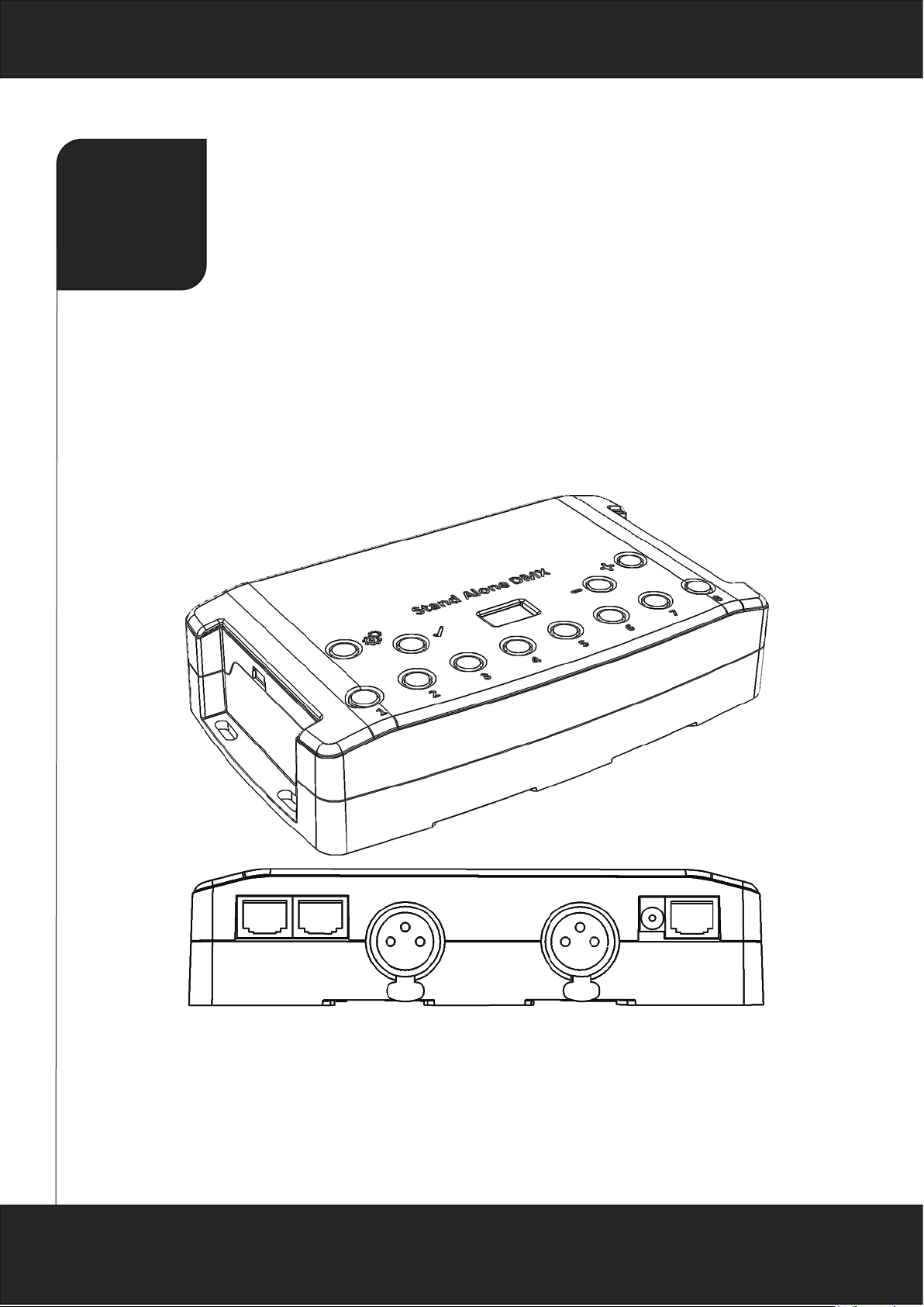
FRONT FACE OF THE ETHERNET INTERFACE
SIDE FACES OF THE ETHERNET INTERFACE
Left Side Right Side
Scene triggering buttons:
1: Scene 1 On/Off
2: Scene 2 On/Off
3: Scene 3 On/Off
4 Scene 4 On/Off
5: Scene 5 On/Off
6: Scene 6 On/Off
7: Scene 7 On/Off
8: Scene 8 On/Off
Command buttons:
: Mode selection (Trigger, Page, Colour,
Speed, Dimmer, Zone)
: Valid Choice / Colour Off
: Decrease values
: Increase values
Display:
7-segments LED display
Mini USB connector and USB power connector
5 DC Volts only; 0,15-1 A.
Micro SD Port
Page 6

Datasheet – Standalone Interfaces USB & Ethernet - DMX 1024 channels 6
TOP FACE OF THE ETHERNET INTERFACE
XLR DMX Signal Connector B
3 Pins. Can be configured in Output
mode (splitter for 512 interface or
output for 1024) or Input mode (PC
for 512, PC and Standalone for
1024).
1: Ground
2: Data 3: Data +
XLR DMX Signal Connector A
3 Pins. Can be configured in Output or Input mode (PC mode only).
1: Ground
2: Data 3: Data +
RJ 45 connector TRIG
1: 5 Volts out
2: Trig 1
3: Trig 2
4: Trig 3
5: Trig 4
6: Trig 5
7: Trig 6
8: Trig 7
Power supply 9V input
DC Connector
RJ45 Ethernet port
Allow to connect the interface to a network
(LAN) via a RJ45 cable
RJ45 connector Input/Output
1: Master/Slave - Clock
2: Master/Slave - Data
3: Light - Data
4: IR Signal from the external IR LED receiver
5: RS232 Tx
6: RS232 Rx
7: 5 Volts out
8: Ground
RJ 45 Pins Order
Page 7

Datasheet – Standalone Interfaces USB & Ethernet - DMX 1024 channels 7
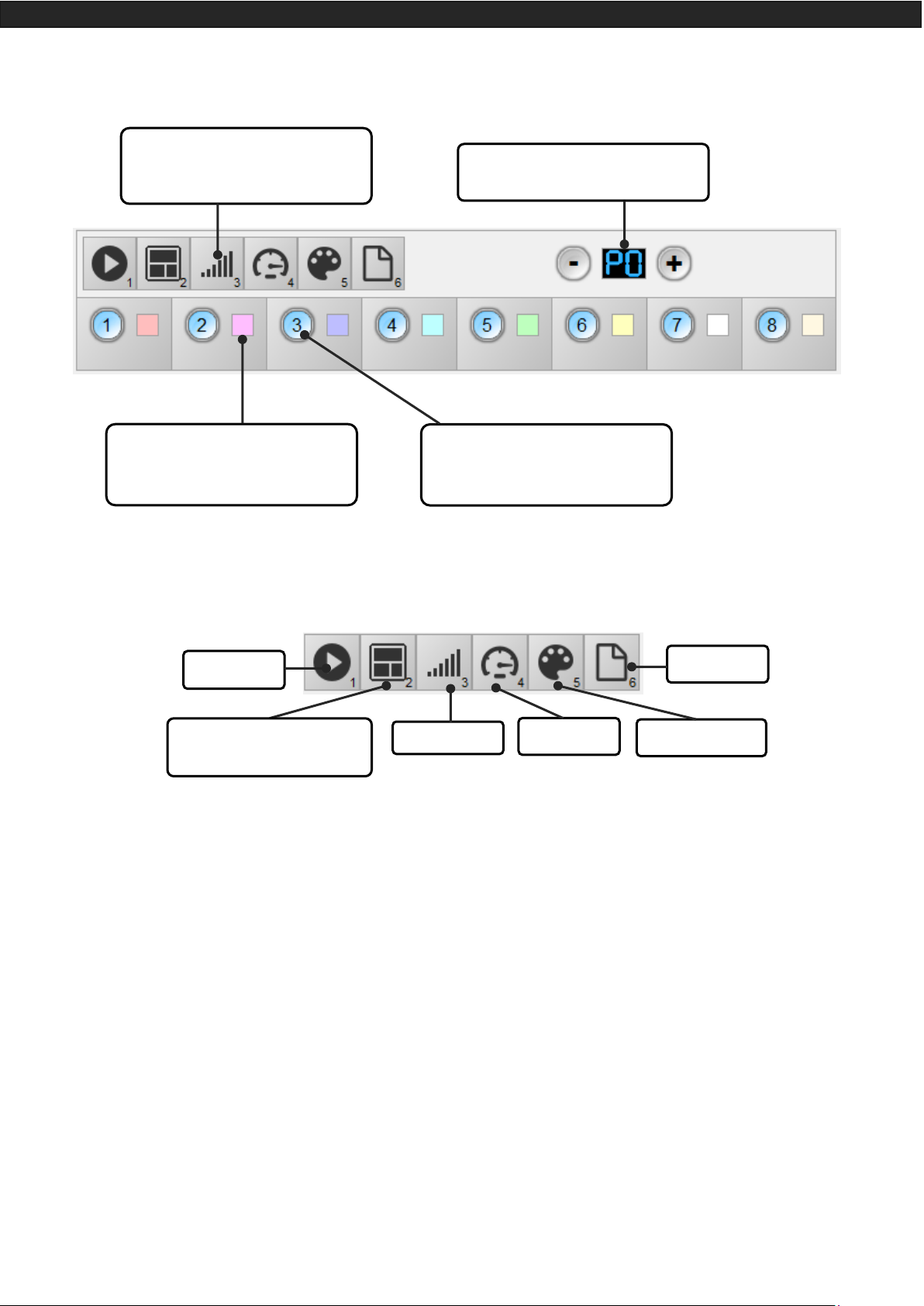
INTERFACE BUTTONS AND DISPLAY FEATURE S
Mode selection button
Press the Button to select one of the available modes: Scene triggers (SA), Page (PA), Colour (Co), Speed
(SP), Dimmer mode (dI) or zone (Zo).
Valid Button
Press the button to validate your choice or turn off the current colour selection.
Hold the button for 4 seconds to switch from IP to DHCP mode. DHCP mode will define a random IP ad-
dress to the device. IP mode will use the fix IP address of the device. And use its default one.
Next/Previous, +/- Scene buttons
Scene trigger mode: Select the scene number with + or – buttons, then press Valid to confirm to play the se-
lected scene from 01 to 255. The scene number will flash several times to confirm your selection.
With scene 00 nothing is playing
Page Mode: Select the scene page with + or – buttons from P0 to P9, then choose the scene available in the
current page with the 8 buttons.
Colour mode: From the 8 buttons, select one of the 8 customized colour or choose the colour of the colour
wheel from 00 to 99 with + or – buttons. Press Valid button to turn off the current colour or recall the last colour from the colour wheel.
Speed Mode: Increase or decrease the Speed of the current scene with + or – buttons. Values are from -9 to
+9.
Dimmer Mode: Increase or decrease the general intensity (dimmer + RGB) of scenes and colours with + or –
buttons. Values are from -9 to +9.
Zone Mode: Select the zone with + or – buttons (Zone A to E and global Zone), then choose the scene availa-
ble in the current zone with the 8 buttons.
Clock setting Mode: Increase or decrease the number to define the year, month, day, hour and minute during
the clock setting with + or – buttons.
Page 8

Datasheet – Standalone Interfaces USB & Ethernet - DMX 1024 channels 8
Blue LED buttons
Push one of the 8 trigger buttons to play a scene in memory from the Scene trigger mode and Page mode.
Push again the buttons with blue LED to stop the current scene.
In colour mode push a button to trigger a personalized colour. Push again to stop it.
LED display operations and meaning :
The LED Display shows the number of the current scene, page, colour, selected modes, speed/dimmer values
and the update firmware mode.
There are different displays according to the selected mode:
PC: The interface is connected to the computer and communicating with the software. The interface is controlled by software.
IP: The interface is in fix IP mode, the default network address is 192.168.0.5.
dh: The interface is in DHCP mode, the network address is defined by the router or the access point.
SA: Scene trigger mode is running. By default, then no scene is playing, all DMX channels are set to 0.
In Scene trigger mode, the LED display gives the current scene number from 01 to 255. The 00 value is Blackout and the DMX interface send nulls (0x00) on all output.
PA: Page mode, it allows to switch between 10 pages of 8 buttons to triggers scenes directly.
In page mode, the display indicates the page number P0 to P9.
Co: Colour mode, to play some customized colours on RGBW channels.
In colour mode, the display indicates the colour number from C1 to C8.
SP: Speed mode, increase or decrease the current scene speed.
In speed mode, the display indicates the speed of the current scene, values from -9 to 9.
dI: Dimmer mode, increase or decrease the general intensity and dimmer of scene and customized colours.
In dimmer mode, the display indicates the general intensity, values are from -9 to 9.
Pr: Programming memory Mode, Pr is display when the interface is writing a show in memory.
Zo: Zone mode is selected. After programmed the interface memory the zone A is selected by default. In zone
mode, the LED display gives the current Zone: General, A, B, C, D, E.
Zone A to D display :
General Zone display :
The LED Display switch between the current zone and the running scene number every 3 seconds.
Page 9

Datasheet – Standalone Interfaces USB & Ethernet - DMX 1024 channels 9
YE: Year setting in the clock setting mode.
Mo: Month setting in the clock setting mode.
dA: Day during in the clock setting mode.
ho: Hour setting in the clock setting mode.
Mi: Minute setting in the clock setting mode.
CL: Confirmation of the new clock setting
bL: Update firmware mode, when a new firmware is writing in memory.
In update firmware mode, the display will flash during the firmware update. Do not disconnect the interface
during this mode.
Page 10

Datasheet – Standalone Interfaces USB & Ethernet - DMX 1024 channels 10
ETHERNET CONNECTION
The Ethernet interface can be connected to a local network (LAN or WLAN) via a RJ45 cable and be detected
by the software installed on a computer connected on the same network.
Connect the RJ45 port n°RJ3 to the network and power the interface with the DC input (5-24V) or the USB (5V).
Hold the button for 4 seconds to switch from IP (iP) or DHCP (dh) mode according to your network.
The default IP is 192.168.0.5, subnet mask 255.255.255.0 and default gateway 192.168.0.1.
DHCP mode is use with an access point, IP switch or Ethernet router.
Fix IP address is use in the same configuration as the DHCP and also with direct connection with the computer
(no access point, router or switch).
Once it is well connected to the LAN, start the software and select “Ethernet", all interfaces on the network will
be detected and displayed in the list. You can uncheck the ones you don't need.
In DHCP mode, if the interface does not receive a valid IP address from the DHCP server, then the interface will
use its fixed IP address to establish the Ethernet communication and the device will display “iP” after few
seconds.
Select Ethernet
Click next
Uncheck the interfaces you don’t want to open
Click next
Page 11

Datasheet – Standalone Interfaces USB & Ethernet - DMX 1024 channels 11
RESET T HE IP ADDRESS
To recover the default IP address (192.168.0.5), hold the buttons and at the same time for 5 seconds.
IP CONFIGURAT ION F R OM SOFTWARE
In the software, it is possible to setup the network configuration of the interface.
Go to "Tools" and "Options" and select the "Device" tab.
In the "Network Config" area, click DHCP to switch the interface to DHCP mode.
To fix the IP address of the device with personal settings, uncheck DHCP and enter the desired IP address,
subnet mask and gateway, then apply your choice.
Select Device
Current interface IP address
Select DHCP
to switch to
DHCP mode
Enter the IP address, subnet mask and gate-
way to switch the interface to IP mode
Apply to validate
your settings
Page 12

Datasheet – Standalone Interfaces USB & Ethernet - DMX 1024 channels 12
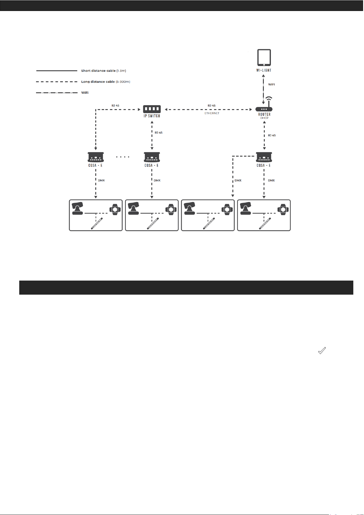
INSTALLATION DIAGRAM
Ethernet to DMX
WIFI to DMX via PC
Page 13
Datasheet – Standalone Interfaces USB & Ethernet - DMX 1024 channels 13
WIFI to DMX Standalone via Wi-Light application
INTERNAL CLOCK SETTING
It is possible to setup the internal interface clock and change or update its date and time manually.
To access the clock mode, hold the ”+” and “-“ buttons for 5 seconds.
“YE” is displayed to configure the current year, then use + and - to select the year and confirm with .
Proceed in the same way for the months “Mo”, days “dA”, hours “ho” and minutes “Mi” setting.
After validate the minutes, “CL” will flash to confirm and save the new configuration.
Then the device clock is up to date.
This mode is very convenient, especially when you need to update the clock on site directly without computer.
Page 14
Datasheet – Standalone Interfaces USB & Ethernet - DMX 1024 channels 14
ZONE MODE
1024 channels interfaces allow to play 5 zones at the same time in standalone mode.
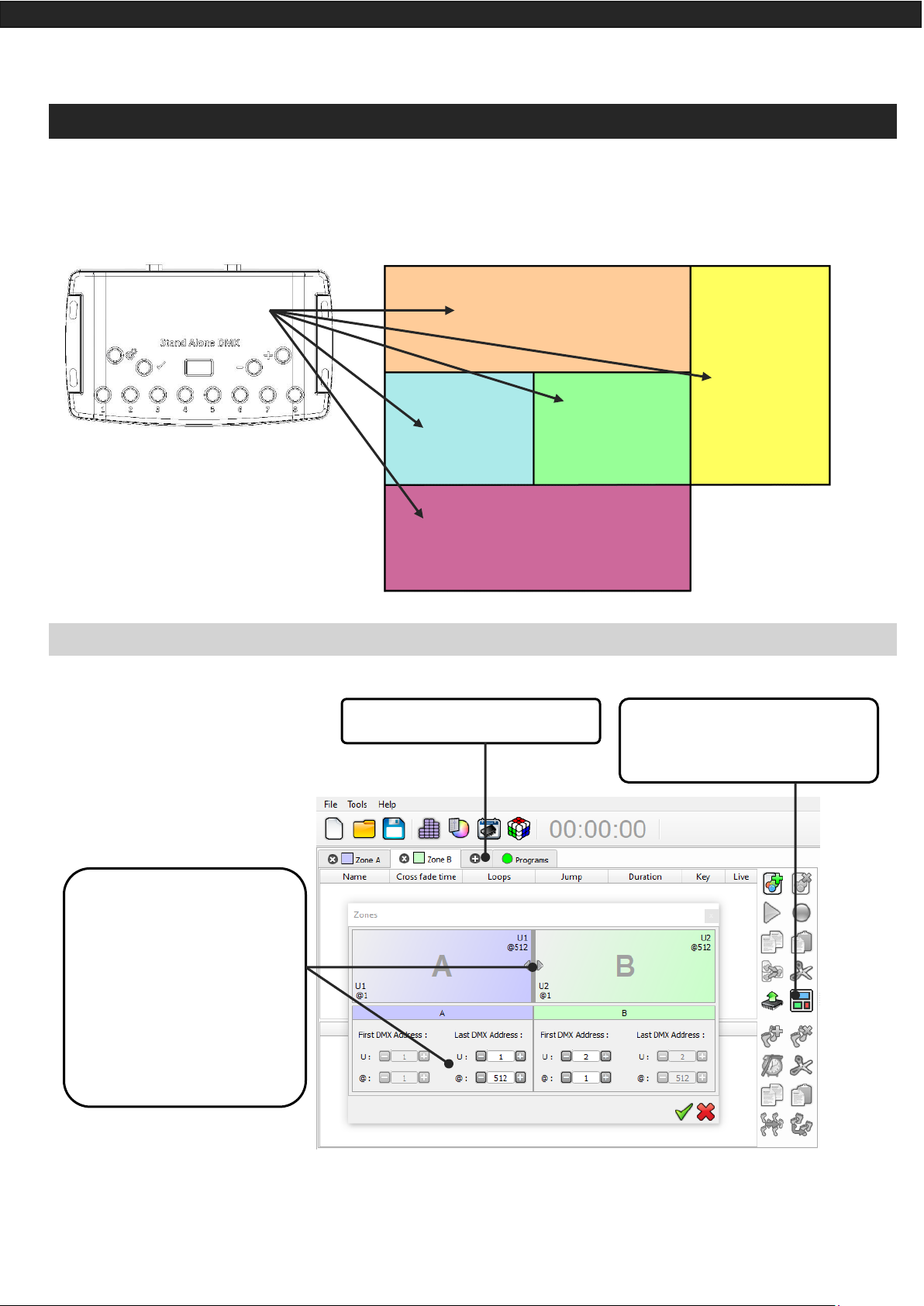
ZONE CONFIGUR ATION IN THE SOF TWARE
In the edition mode :
When zones are defines, you need to create scenes in the corresponding tab :
Zone 1
Bar
Zone 2
Patio
Zone 3
Room 1
Zone 4
Room 2
Zone 5
Room 3
Click on + to add zones
In the zone window, move the
central bar to define the zone
parameters, it is also possible to
choose manually the zone range
in the fields.
Make sure your DMX Patch and
fixtures addresses are corresponding to your Zones.
The zone window can be display by
clicking on the « Zone » button
Page 15

Datasheet – Standalone Interfaces USB & Ethernet - DMX 1024 channels 15
In Standalone Mode :
The « Zones » tab allows to
display and configure each
zone (double click on a zone to
edit)
The Zone option is available in
Standalone mode (Manuel selection of zones)
Page 16
Datasheet – Standalone Interfaces USB & Ethernet - DMX 1024 channels 16
STANDALONE INTERFACE TRIGGERS
The Standalone mode of the software enable to configure and personalize all the triggers.
The information will be directly saved in the DMX interface memory with the memory writing function.
SWITCH TO STANDALONE MODE
When the device isn't connected to the software or has just been powered, it enters in Standalone mode after
five (5) seconds.
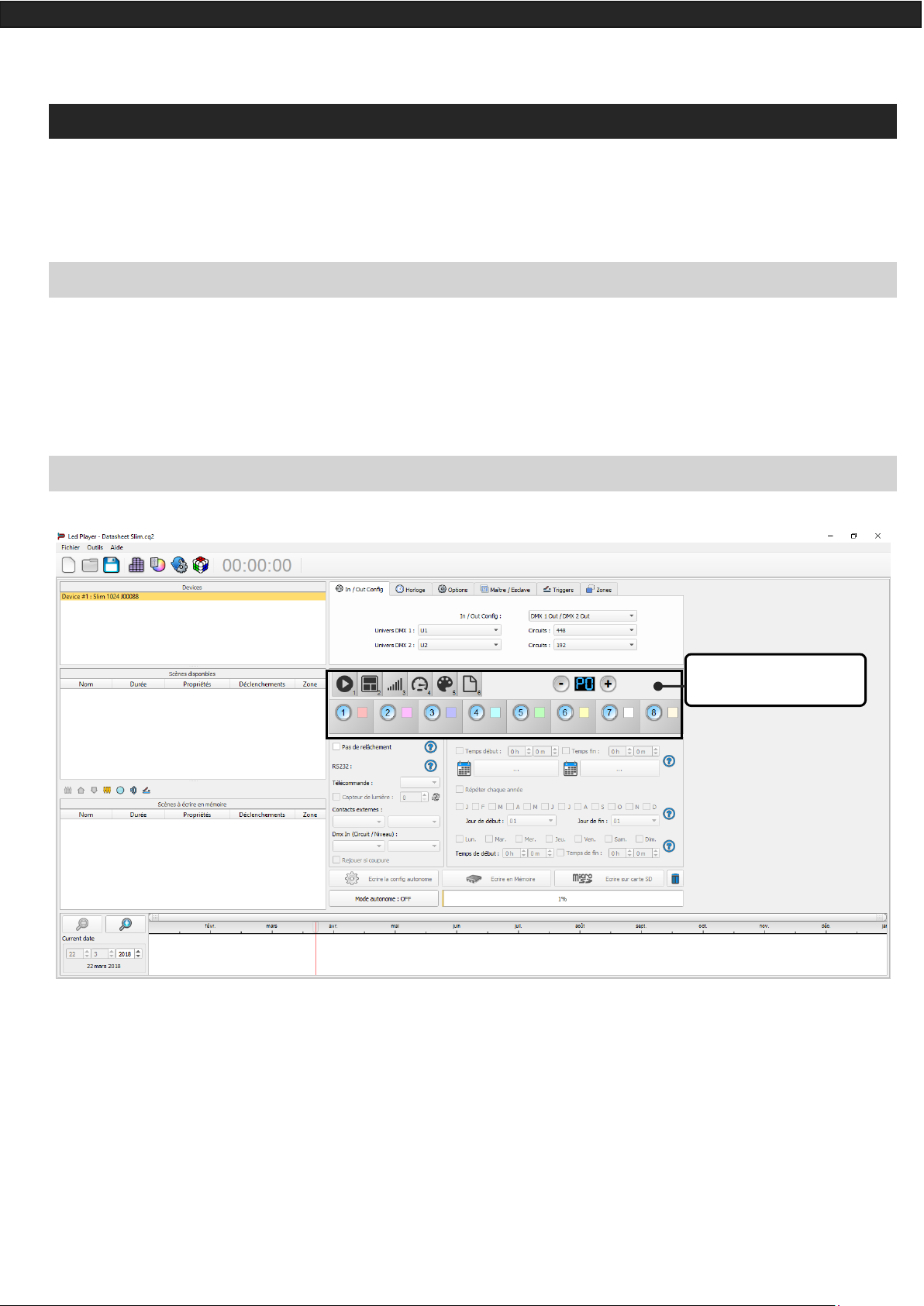
INTERFACE MODE SETTINGS
Device settings windows
Page 17
Datasheet – Standalone Interfaces USB & Ethernet - DMX 1024 channels 17
Organizes menus available in
standalone mode
Page selection Buttons
Choose a RGBW colour to be
played in standalone colour mode
(8 colours max.)
Associate scenes to buttons to be
played in standalone scene mode
(80 scenes max.)
Scene Mode
Page Mode
Colour Mode
Speed Mode
Dimmer Mode
Zone Mode (1024 channel
Interfaces)
Page 18

Datasheet – Standalone Interfaces USB & Ethernet - DMX 1024 channels 18
It is possible to personalize the mode that you want to use in Standalone.
From the mode icons, you can right click to Add or Remove a mode. Drag and drop a mode in the list to order
them accordingly to your need.
You can also choose a single menu to simplify the use of the interface.
Drag and Drop to organize
modes
Right click on a mode to
remove it
Click on + to add a mode
Page 19

Datasheet – Standalone Interfaces USB & Ethernet - DMX 1024 channels 19
LED BUTTONS TRIGGER
Standalone mode offers 8 buttons that represents the interface LED buttons. From the scene list of the
standalone mode, you need to drag and drop a scene on any button to assign a button number.
It's possible to replace a scene by another one or to remove it by pulling it out of the list.
You can also setup a colour to each button and play this colour in the colour mode, click on colour square to
set your own colour.
Click and set the desired
colour
Drag and Drop a scene to a
button
Page 20
Datasheet – Standalone Interfaces USB & Ethernet - DMX 1024 channels 20
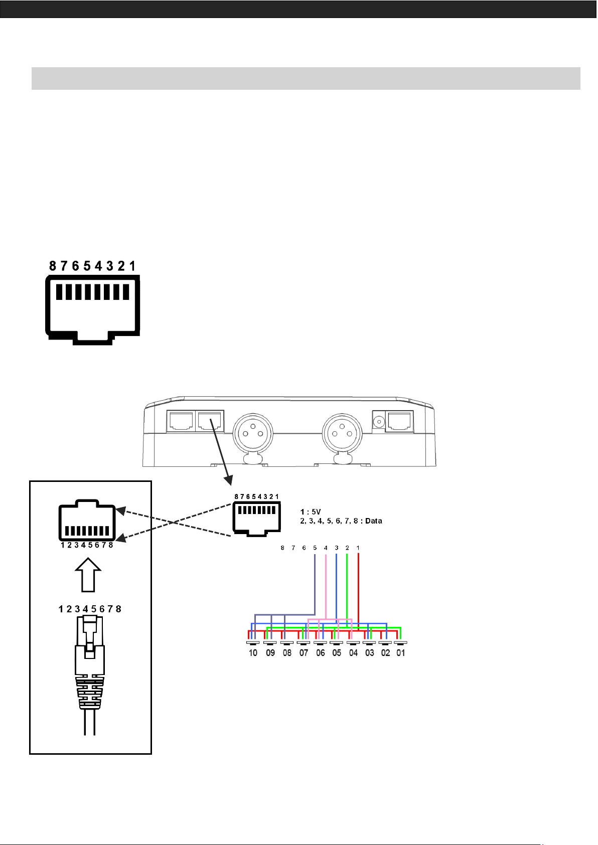
CONTACT WIRING AND CONNECTIONS WITH RJ45 PINS
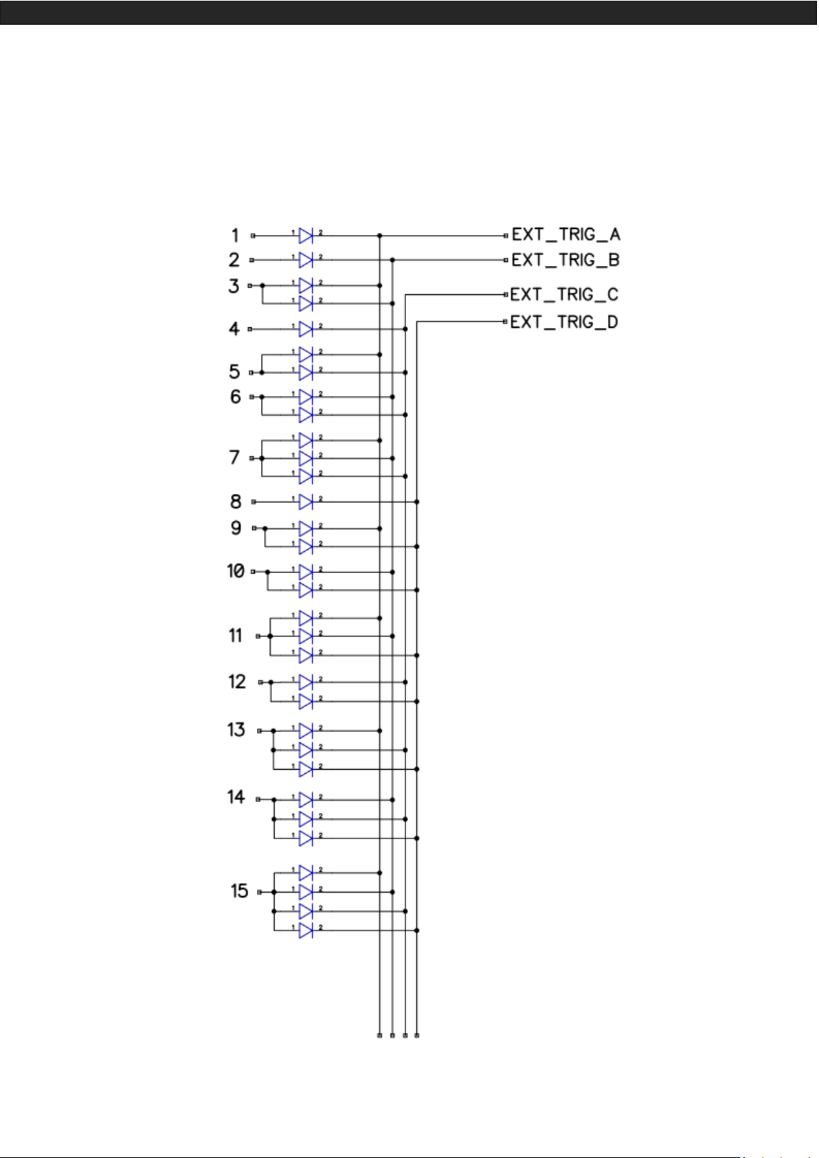
The 7 externals contacts are located on the RJ45 connector number 2. You can use the 7 dry contacts to trigger
7 scenes via external relay. To have more triggers you must use a multiplexed system to get a maximum of 127
contacts as following:
Multiplex the trigger could give 127 triggers combinations
Front view of the interface
RJ 45 connector
External Contact Closures can be done only when Pin 2, 3, 4, 5, 6,
7, 8 are connected to Pin 1 (5 V. DC). (up to 127 triggers)
Pin Table:
Trigger 01 = Pin 2
Trigger 02 = Pin 3
Trigger 03 = Pin 2 + 3
Trigger 04 = Pin 4
Trigger 05 = Pin 2 + 4
Trigger 06 = Pin 3 + 4
Trigger 07 = Pin 2 + 3 + 4
Trigger 08 = Pin 5
Trigger 09 = Pin 2 + 5
Trigger 10 = Pin 3 + 5
Trigger 16 = Pin 6
Trigger 32 = Pin 7
Trigger 48 = Pin 6 + 7
Trigger 64 = Pin 8
Trigger 100 = Pin 4 + 7 + 8
Etc…
Page 21
Datasheet – Standalone Interfaces USB & Ethernet - DMX 1024 channels 21
Dry contact reaction time: 8 ms (0.008 s) / Time between 2 contacts: 500 ms (0.5 s)
Dry contact trigger options : On (Start scene only) + On/Off (start and stop scene) + Auto release (Hold contact
to play scenes) + Restart (restart scene from beginning) + Play in priority (Scene keep playing until it pause or
stop, no other triggers allowed while playing).
Page 22

Datasheet – Standalone Interfaces USB & Ethernet - DMX 1024 channels 22
By selecting a scene in the list, it's possible to choose the external contact number (from 01 to 127) to trigger
the scene.
By default, the interface gives 7 external contacts (01, 02, 04, 08, 16, 32, 64). To obtain 127 external contacts,
you have to use a de-multiplexing interface in order to go use the other possible combinations.
Several trigger options are available for externals contacts triggers:
On: Activate the contact only allow you to play the scene.
On/Off: Activate the contact allow you to play and stop a scene. Each trigger action will invert the state of the
scene (start/stop).
Auto Release: The scene plays while the contact is activated. Keep the contact activated to play the scene,
when the contact is released the scene stop.
Restart: Activate the contact will restart the scene from its beginning automatically. If the scene is off already,
then it will play.
TRIGGERING COMMANDS
External contacts can also trigger commands in standalone mode. >From the Triggers tab you can select a
contact for each action: Dimmer + , Dimmer -, Blackout, Speed +, Speed -, Pause, Scene +, Scene - and Area.
It is not possible to use the same trigger for scene and command, in this case, the scene contact has the priority or the scene will lose its contact trigger information after choose the contact from the Trigger command
tab.
Page 23

Datasheet – Standalone Interfaces USB & Ethernet - DMX 1024 channels 23
IR REMOTE CONTROL UNIT AND IR RECEIVER
Button 1 to 10 must be assigned to a scene via the software.
Each button can trigger a different scene. With the remote control, a
scene cannot be stop directly with the assigned button. To stop it
you must press the Stop/Black Out button or trigger another scene.
Pause button to freeze the current scene to its actual state.
Stop/Black Out button to stop the current scene and play the empty
scene number 00. All DMX channels are set down to 00 levels.
+/- for scene trigger. Select the next or previous scene automatically. You don't need to hold the button to validate and play a scene.
The next or previous scene will play directly after selected.
+/- for Scene speed. Increase or decrease the speed of the current
scene. A different speed can be chosen separately for each scene.
+/- for General dimmer. Increase or decrease the RGB, CMY and
dimmer channels of the fixtures. The CMY, RGB, Dimmer channels
are defined in the Profile of the fixture.
To use the IR remote control, an external PCB with an IR receiver LED
must be connected before to the RJ45 #1 of the Standalone interface. The standard RJ45 cable distance is about 20 meters maximum.
IR PCB Pin assignment:
-With RJ45 use pins #8 = Ground; #4 = IR Data ; #7 = 5V DC.
-With T. Block use pins: O = IR Data; V = 5V DC; G = Ground.
Page 24

Datasheet – Standalone Interfaces USB & Ethernet - DMX 1024 channels 24
In the software go to Standalone Mode and use the Triggers options to assign a remote button to a scene.
Standalone mode offers up to 10 triggers with the Infrared remote.
By selecting a scene in the list, it's possible to choose the remote button number (from 01 to 10) to trigger the
scene.
DMX IN TRIGGER CONNECTION
DMX-B Must be
turned into Input in
the software
Standard DMX
Controller board
The DMX Output is
connected to the inter-
face input
DMX Output, play
scenes in memory and
trigger with de DMX
Board via the DMX IN
signal
Page 25

Datasheet – Standalone Interfaces USB & Ethernet - DMX 1024 channels 25
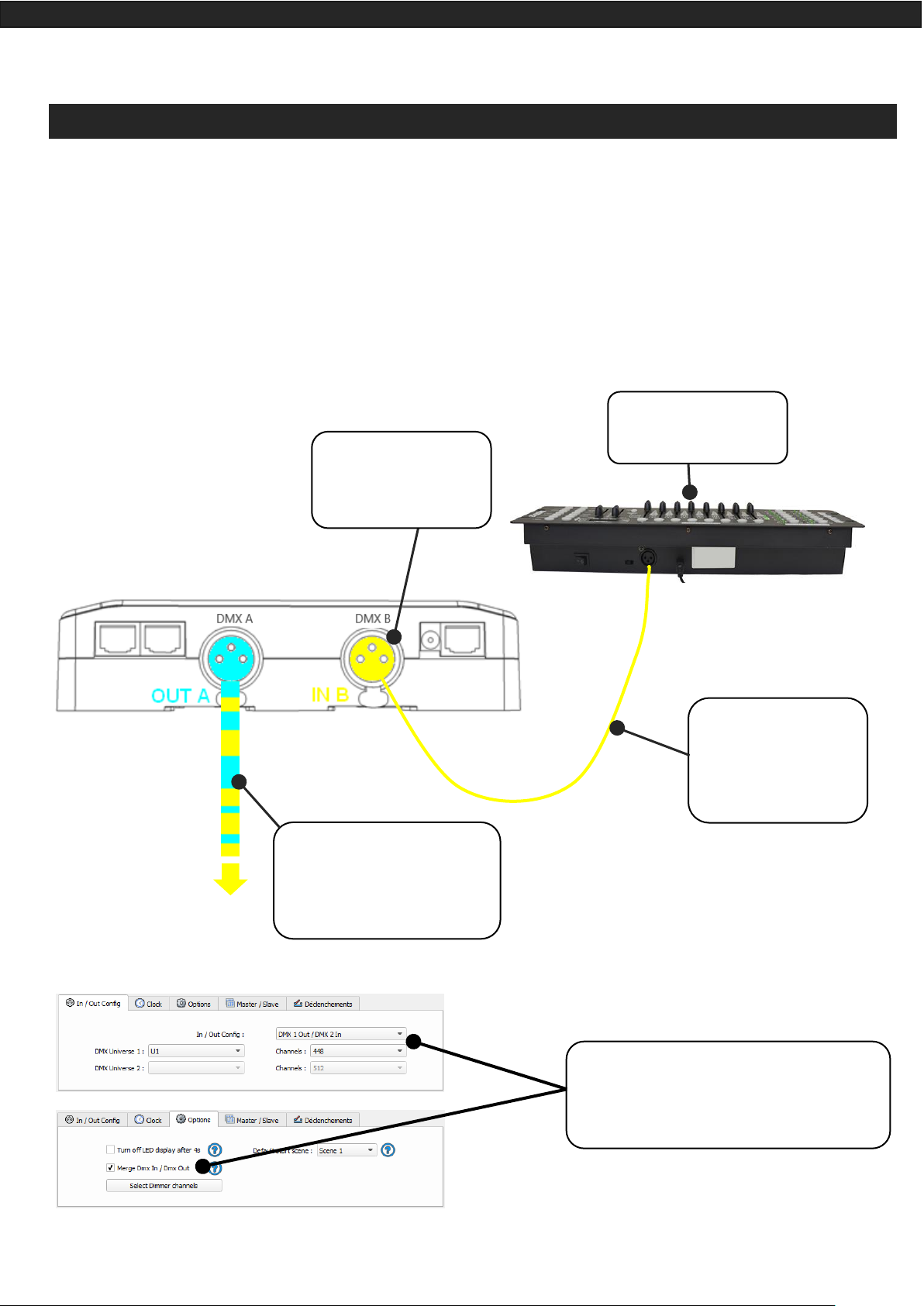
DMX IN TRIGGERS VIA ANOTHER DMX SIGNAL IN STANDALONE
DMX in trigger in standalone available only with 1024 interfaces.
In standalone window set In / Out Config as DMX 1 Out/DMX 2 In and select the DMX Out universe
The Standalone mode offers up to 512 DMX IN channel triggers and up to 255 DMX trigger values per channel. By selecting a scene in the list, it's possible to choose the channel number and the DMX value to trigger
the scene. The scene will play when the value of the DMX channel is reached or exceeded.
Page 26

Datasheet – Standalone Interfaces USB & Ethernet - DMX 1024 channels 26
SETUP DMX IN MODE IN SOFTWARE USE
In software one DMX Output must be turned into an input in the Options windows. To access this window,
click on the software menu: Tools > Options then click to select the device section as following:
You can select a universe for output and input mode with 1024 and 512 interfaces.
Follow those steps to set a DMX-IN trigger on a scene or on a program:
Step 2: Double click
the “Key” cell of the
scene to be triggered.
Step 3: Go to the
DMX section of the
Key window.
Step 1: Go to the
scenes list in the editor view.
Device Section
Define input
Page 27

Datasheet – Standalone Interfaces USB & Ethernet - DMX 1024 channels 27
Two DMX-IN trigger options are available: DMX Level and DMX Scale, let’s see what the differences are:
Option DMX Level
Choose the input universe
and channel
Choose the trigger level
witch one if you go over
it the scene starts and
under it the scene stops.
Option DMX Scale
Choose the input universe
and channel
Choose the trigger range
of levels. Witch one if
you go inside it the
scene starts and outside
it, the scene stops.
With the DMX Scale you can create many triggers presets on a
same DMX-IN channel and so
starts a suite of scenes on the
DMX fader way.
Page 28

Datasheet – Standalone Interfaces USB & Ethernet - DMX 1024 channels 28
RS232 TRIGGERS IN STANDALONE
Standalone mode allows to use the RS232 protocol to control the DMX interface with the commands describe
in the help topic
Connect the RS232 transmitter to the interface RS232 and GND pins and send the dedicated ASCII commands
lines that you need.
The ASCII commands need to be sent one time only to be processed by the interface.
Page 29

Datasheet – Standalone Interfaces USB & Ethernet - DMX 1024 channels 29
Page 30

Datasheet – Standalone Interfaces USB & Ethernet - DMX 1024 channels 30
TIME TRIGGERS WITH CLOCK AND CALENDAR
The Standalone mode has an internal clock and a calendar. It's possible to assign a time trigger on every scene
of the list. By selecting a scene on the list, it's possible to choose the start and end dates and hours and days of
the week. You can thus create a lot of scenarios.
CASE 1: Programming a unique trigger:
• Start schedule:
The scene is triggered a single time at the given date and time.
• End schedule:
The scene is stopped at the given date and time.
CASE 2: Programming a repeating trigger:
• Start schedule:
Date from which-one the scene will be playable according to the programmed triggers
• End schedule:
Date after witch-one triggers will be ignored. With no End date, triggers are permanent
Page 31

Datasheet – Standalone Interfaces USB & Ethernet - DMX 1024 channels 31
• List of the months of the year
The 12 check boxes represent the 12 months of the year (J) January to (D) December. The triggers will be
performed on the activated months. Next, a daily hour range must be defined.
• Start and Stop days
With a monthly repetition, you can choose the starting and stopping days for each chosen month.
In this example triggers can happen between the 1st and the 15th of each chosen month.
• List of the days of the week
The 7 check boxes represent the 7 days in a week. The triggers will be performed on the activated days
only. Next, a time range must be defined.
• Start time
The starting time is the time when the scene will be triggered for each chosen day. Of course, chosen
months, start and end schedule days are included.
• Release time
The release time is the time when the scene will stop for each chosen day. Of course, chosen months, start
and end schedule days are included. The release time is not mandatory, if it’s not defined, the scene will
keep playing until another trigger event happens. (Like the triggering of another scene for example).
NOTE: For a daily repetition, if the the starting time is later than the release time then the triggering will stop
the next day, even if the next day has not been selected.
Page 32
Datasheet – Standalone Interfaces USB & Ethernet - DMX 1024 channels 32
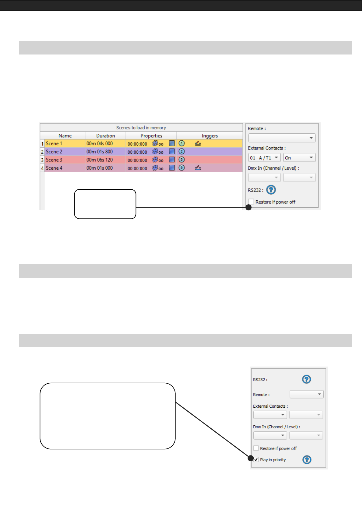
SAVE AND RECOVER THE LAST SCENE AFTER THE POWER CUT OFF:
The interface can save the last scene played before the power cut off and recover it when the power is restored.
For each scene you can select “Restore if power off”
SCENE TRIGGER PRIORITIES:
When several scenes have the same time trigger (date + hour + minute), only the first scene in the list will be
triggered. The rest will be ignored
PLAY IN PRIOR ITY
Click for enable the
Restoration option
Click to enable the Play in priority option:
The scene will keep playing. No other triggerings allowed (contacts, Infrared, DMX, RS232)
while the scene is playing (exept Time/calendar schedules and buttons)
Page 33
Datasheet – Standalone Interfaces USB & Ethernet - DMX 1024 channels 33
DMX MERGING IN STANDALONE
One DMX line must be turned into an input to capture the DMX signal provided by an external DMX board or
by another DMX interface.
The interface will merge the incoming signal with its own output signal by comparing the DMX levels with a
HTP filter (priority on the highest levels of the signals). Merging is a solution to keep manual control on channels, using a DMX Board for example. It’s also a way to create a multi-zones system by merging several interfaces on one final DMX line. In this last case, each interface can play a scene dedicated to the fixtures at the
same time and on the same DMX line.
Standard DMX
Controller board
DMX-B Must be turned
into Input in the soft-
ware
The DMX Output is
connected to the in-
terface input – LINE B
mandatory
DMX Output A is a merge be-
tween what the interface is
playing and what is coming in
the input line B.
In the software’s standalone window, select:
“DMX 1 OUT / DMX 2 IN” and validate the
merge option.
Page 34
Datasheet – Standalone Interfaces USB & Ethernet - DMX 1024 channels 34
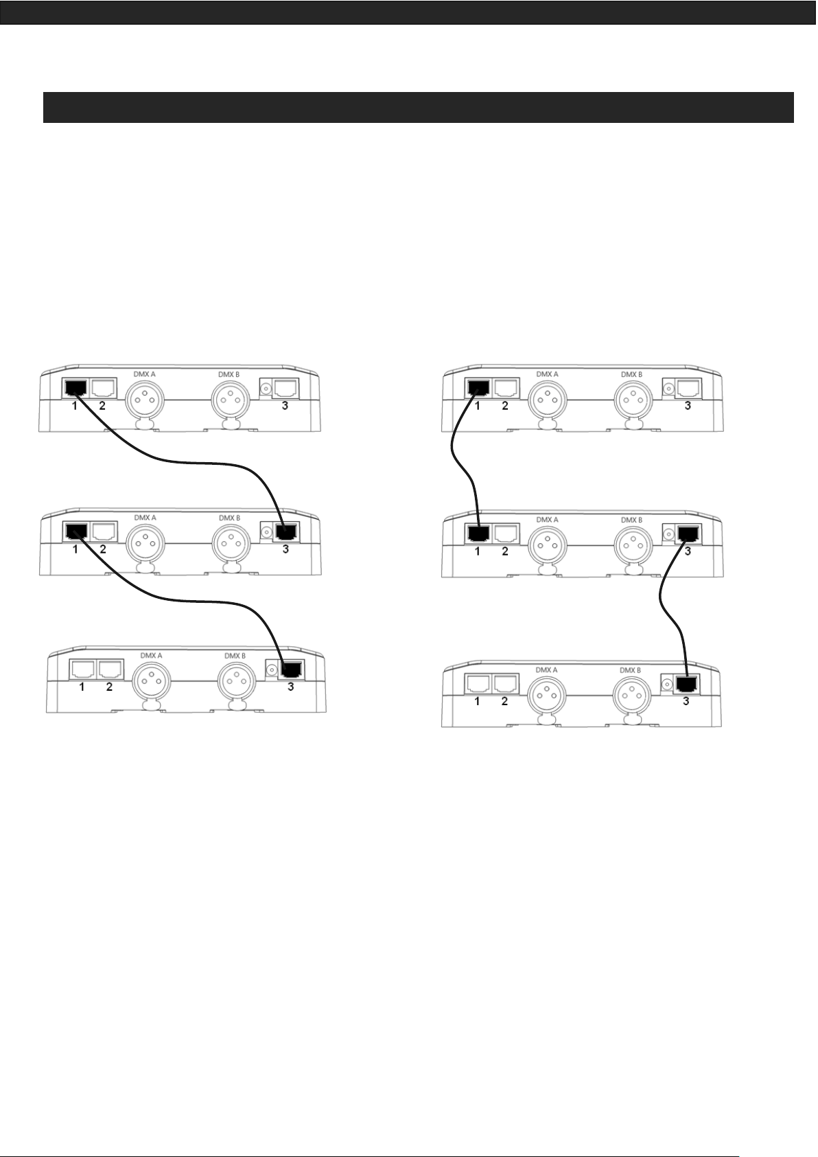
CONFIGURATION OF THE MASTER/SLAVE INTERFACES
When multiple interfaces are connected with USB, the standalone mode allows to set them as Master/Slave.
This mode allows to synchronise many interfaces and mutualize their standalone spaces combining the universes. (up to 32 standalone universes)
Here are two example or wiring with 3 interfaces plugged as Master/Slave with standard Ethernets cables. You
must connect Ethernet sockets 1 or 3 in any order:
Master
Slave
Slave
Master
Slave
Slave
Page 35
Datasheet – Standalone Interfaces USB & Ethernet - DMX 1024 channels 35
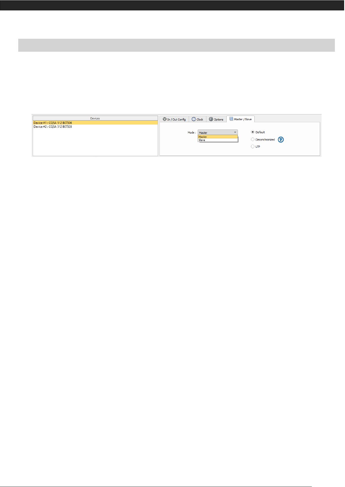
SETTING OF THE MASTER/SLAVE INTERFACES
A single interface can be defined as master, others are automatically set to slaves. Triggers operated on the
master interface are passed on slaves. However, slaves are not synchronized on play time and keep individual
control. Consequently, slaves can trig and play different scenes. The master acts like a general remote imposing triggering to the slaves.
• MODE MASTER/SLAVE « Default »
A single interface can be defined as master (lower serial number by default), others ones are automatically set
to slaves. The master device plays the current scene and synchronize the slave ones. The master forces the
slave interfaces to play the same scene and the same step at the same time. The slave interfaces are forced to
follow the master timings and triggers and they cannot act, play or trigger a scene independently. Master can
trigger on and trigger off scenes of the slave interfaces.
• MODE MASTER/SLAVE « Desynchronized»
An interface can be defined as master, others are automatically set to slaves. All Triggers On or Off operated
on the master interface are effective to slave ones. However, slave interfaces are not synchronized with master's timing and keep individual controls. Consequently, slaves can trigger and play different scenes at any time
and not synchronized with the master ones. The master acts like a general remote imposing triggering to the
slaves with total priority. Master can trigger ON and trigger OFF scenes of the slave interface.
• MODE MASTER/SLAVE « LTP »
LTP means Latest Takes Priority. All interfaces are defined as slaves. Interfaces are not synchronized with timing
and can trigger and play different scenes by itself. However, triggers from an interface are passed to the others
connected interfaces automatically and slave interfaces are forced to trigger the same scene. Here each interface acts like a general remote imposing triggering to the other slaves without synchronization.
• THE «NO RELEASE» Option
This option is only available with LTP or DESYNCHRONIZED modes. Only triggers ON from the master interface
are executed and effective. All triggers OFF are ignored and slave interfaces keep playing their current scene.
Each Slave interface can choose to release or not its scene depend on the option is activated or not.
Page 36

Datasheet – Standalone Interfaces USB & Ethernet - DMX 1024 channels 36
SD CARD
It is possible to save your show on micro SD card. The Card must be format as FAT 32 and 16 Gb Maximum.
In standalone mode, click to “Save on SD card”, select a place to save the show on the computer or directly at
the micro Sd card root.
To play in standalone the SD show, insert the card into the CQSA micro SD slot and when the card is booted,
the display will show "Sd" to indicate that the SD show is playing.
The show file must be paste to the micro SD root, it cannot be played if it is renamed.
BATTERY
The battery allows to keep the clock and calendar settings in memory when the device is not powered.
The clock can keep the time and date up to 10 to 30 days, depending on the charging time and the type of
battery included.
The device must be powered few hours to fully charge the battery.
DIMENSIONS OF THE INTERFACE
The metric system is used. The unit is mm.
TOP FACE
34
38
8
28
14
22
12
16
14
44
50
22
166
Page 37

Datasheet – Standalone Interfaces USB & Ethernet - DMX 1024 channels 37
SIDE FACES
BOTTOM FACE
60
32
95
32
156
5
43
68
25
23
18
86
146
6 3 31
20
8
4
25
38
35
97
Page 38

Datasheet – Standalone Interfaces USB & Ethernet - DMX 1024 channels 38
MULTIPLE USB DEVICES CONNECTIONS
POWER SUPPLY WITH EXTERNAL + USB
The external power supply is only for Standalone mode. If a USB cable is connected when the device is operating in standalone mode, it reboots to allow the connection to the computer. If scenes are playing in standalone
mode it stops them.
Page 39

Datasheet – Standalone Interfaces USB & Ethernet - DMX 1024 channels 39
STANDARD DMX 512 INSTALLATION
RECOMMENDED DMX512 INSTALLATION
 Loading...