

Page 1
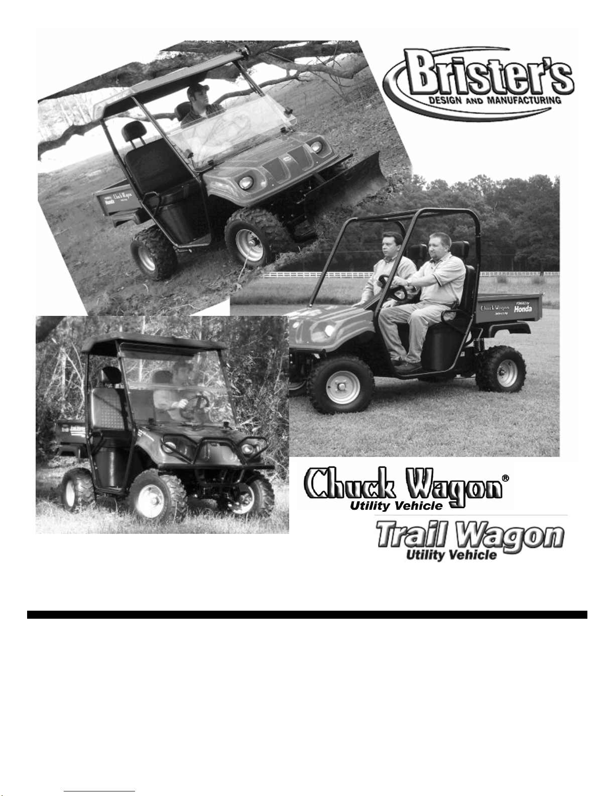
Brister’s Utility Vehicles
2 Wheel & 4 Wheel Drive Models
Operator’s Manual
Copyright
January 1, 2007
Page 2

DIN EX
Section 1 Introduction pages 3-4
Serial Number Plate Location page 4
2 10 Section Safety pages 5-
Pre-Delivery Steps page 9
Dealer Inspection Checklist page 10
ection 3 Assembly Instructions pages 11-13 S
Seat Back, Brush guard, Bumper page 12
Steering wheel page 12
Cargo Bed page 13
Seat Base page 13
Section 4 Operating Instructions page 14
Section 5 Maintenance pages 15-22
Fuel Valve Lever page 15
Air Cleaner Page 16
Engine Oil page 17
Transaxle Oil page 18
Drive Belt page 19
Section Troubleshooting pages 20-28 6
Troubleshooting Chart page 26
ection 7 Parts Diagrams pages 29-64 S
Wiring Diagram page 30
11hp 2 wheel drive pages 31-42
265cc 2 wheel drive pages 43-53
13hp 4-wheel drive pages 54-64
arranty Policy page 65 W
Contact Information
page 66
Warrant ate
y Registration Certific page 67
2
Page 3

Section 1 Introduction
Brister’s welcomes you to its growing family of new
product owners. This Brister Utility Vehicle UTV is a
light utility vehicle that has been designed with care
and built by skilled workers using quality materials.
Proper set-up, maintenance and safe operating
practices will help you get years of satisfactory use
from this vehicle.
Safety First
Brister’s is fully aware of the need for safe operating
procedures around all of our equipment. We hope yo
will make a sincere effort to put safety above au ll other
riorities. The Brister Utility Vehicle was designed and
p
built for work, recreation, and enjoyment; however,
improper and irresponsible operation could result in
serious injury or death. Since this is an off-road vehicle,
operators will seldom see the road safety and warning
signs they are accustomed to seeing on highways and
public streets. This places additional responsibility on
the driver to operate this vehicle well within the safe
operational limits and capabilities of the unit.
This manual has been pre
safe and responsible operation of your Brister Utility
Vehicle. Read and abide by all safety alert information
about this vehicle. If you do not understand any part of
this manual, contact your local dealer for additional
information and clarification. As the operator of this
iece of equipment, you are in complete control. Only p
you can prevent an accident from happening.
pared to instruct you in the
Using This Manual
* Prior to any vehicle operation it is absolutely essenti
that you read and compreh
anual to develop an understanding of your vehicle and
m
for your safety. After reviewing this manual, store it in
dry and easily accessible place for future reference.
The Operator’s Section is designed to help familiarize
*
you with safety, assembly, operation, adjustments,
troubleshooting, and ma
and follow
and efficient operation.
* The information contained within this manual was
current at the time of printing. Some parts may change
slightly to assure you of the best performance.
* To order a new Operator’s or Parts Manual contact
y our au
the recommendations to help ensure safe
thorized dealer.
end each section in this
intenance. Read this manual
al
a
Brister’s Design & Manufacturing Co. LLC
Toll Free PH: 1-866-646-5278
Fax: 1-866-329-5278
www.bristers.com
Terminology
Right-hand and left-hand as used in this manual are
determined by facing the direction the vehicle will travel
while in use unless otherwise stated.
Getting Acquainted with your Utility Vehicle
This off-road utility vehicle is a very unique vehicle
designed exclusively for off-road use. It is not designe
properly equipped, or licensed to be safely operated on
public streets and highways. This vehicle is designed to
carry two people and a limited amount of gear or cargo
comfortably and safely over rough terrain that was onl
accessible by ATV’s in the past.
Unlike ATV’s that have handlebar steering, Brister Utilit
Vehicle’s have a steering wheel with easy handling
rack-and pinion steering. The steering’s tight turning
radius makes this vehicle more maneuverable than
most ATV’s. Its four wheeled independent suspensio
large diameter hi-flotation tires and high center-frame
ground clearance adds up to excellent stability and a
smooth ride over rough terrain. Outstanding two
wheeled rear traction drive is achieved by using
premium off-road ATV type tires in tandem with the
engine mounted directly in front of the
lso unlike an ATV’s one person “straddle saddle” seat,
A
e Brister Utility Vehicle sports dual headrest
th
ushioned seats with seat belts mounted in a highly
c
styled and protective full length body. Two passen
can ride comfortably in this vehicle protected from
shing water and mud. The Brush Guard Bar
spla
mounted to the vehicle’s frame provides protection
against low hanging limbs and briars.
rear differential.
d,
y
y
n,
gers
3
Page 4
Section 1 Introduction
The Brush Guard Bar also provides a mounting system
for Brister’s optional windshields, canopy tops and
weather enclosures. It also serves as a mounting base
for many other optional cargo racks, gun and bow racks
The cargo bed is for transporting accessories such as
camping equipment, tree stands, hunting gear, and
fishing gear. A standard hitch moun
uick installation of a rear hitch for pulling small trailers
q
full of supplies, tools, gear, and game.
The Brister Utility Vehicle has some similarities to
ATV. Like an ATV the Brister Utility Vehicle has a short
wheelbase, narrow stance, and high center clearance a
which provide for narrow and difficult trail access. This
combination of short wheelbase
nables this vehicle to be loaded in the back of most full
e
to mid-sized pickups for t
The Brister Utility Vehicle’s ground compaction and is
very gentle on the ground and surrounding vegetation.
The highly energized four wheeled independent
suspension system provides an incredibly soft ride and
outstanding stability over difficult terrain. The engine
EPA certified and meets California Air Resources Board
ARB) certification (C stand
ransport.
ards.
ting plate enables
and narrow stance also
an
is
Owner Assistance
The safety information should be view
nd the Warranty Registration card should be filled out
a
by the dealer at the time of purchase. The owner, upon
purchasing the vehicle, should have participated in a
short drivers training course with the dealer. This
information is neces
customer service.
T
he parts on your B le Utility Vehicle rister Utility Vehic
have been spec
replaced with g
If customer service or repair parts are required contact a
Brister’s dealer. They have trained personnel, genuine
repair parts and equipment specially designed to repair
Brister’s products.
sary to provide you with quality
designed and sho
ially uld only be
enuine Brister’s parts.
ed by the owner
Product Support
Brister’s Design & Manufacturing Co. LLC
P.O. Box 649
Roseland, LA 70456
Toll Free PH: 1-866-646-5278
Fax: 1-866-329-5278
.
ll
Always use the serial and model number when ord
arts r your Brister Utility Vehicle. The serial-num
fo ber
p
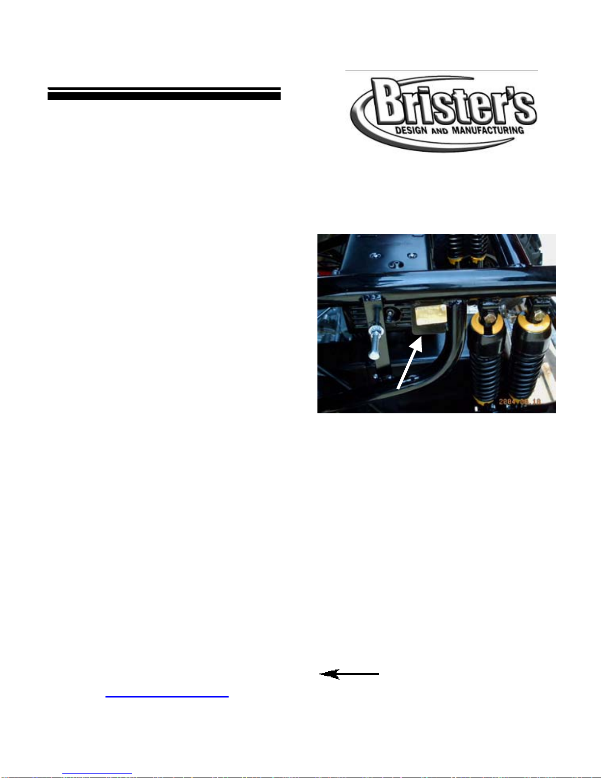
plate is located under the cargo bed on the driver’s side
just above the engine, on the frame as shown in figure 1
below.
Record your Brister Utility Vehicle serial number here for
quick reference:
Model Number:___________________________
Serial Number:___________
Your Brister’s dealer ur
new vehicle. If y
manual o
please ak fo
Discuss the matter with your dealership service
manager. Make sure they are aware of any problems so
they can assist you.
If you are still unsatisfied, seek out the owner or general
manager of the dealership.
Serial Number Plate Location
Figure 1
wants you to be satisfied with yo
ou do not understand any part o
r you’re not satisfied with the service received,
t e the llowing actions.
For further assistance write to
_________________
ering
f this
4
Page 5

Read These Important Rules for Safe Operation
Note: The Operator, Passenger, Parent or Guardian must read, study and understand all the items contained
within this owners/operators manual before operating utility vehicle. Failure to follow these instructions
could endanger the personal safety of the Operator, Passenger and any Bystanders.
When transporting any Brister Utility Vehicle with an installed windshield or
Close adult supervision is required at all times!
Pay close attention to all Caution and Warning labels
Located on the Utility Vehicle
*IMPORTANT*
Color matched top DO NOT reach high speeds!
Assumption Of Risk
The owner or operator assumes all the risks incident to or arising out of the operation of
this Utility Vehicle
Failure to follow and comply with all warnings may
cause serious injury or death
5
Page 6
Section 2 Safety
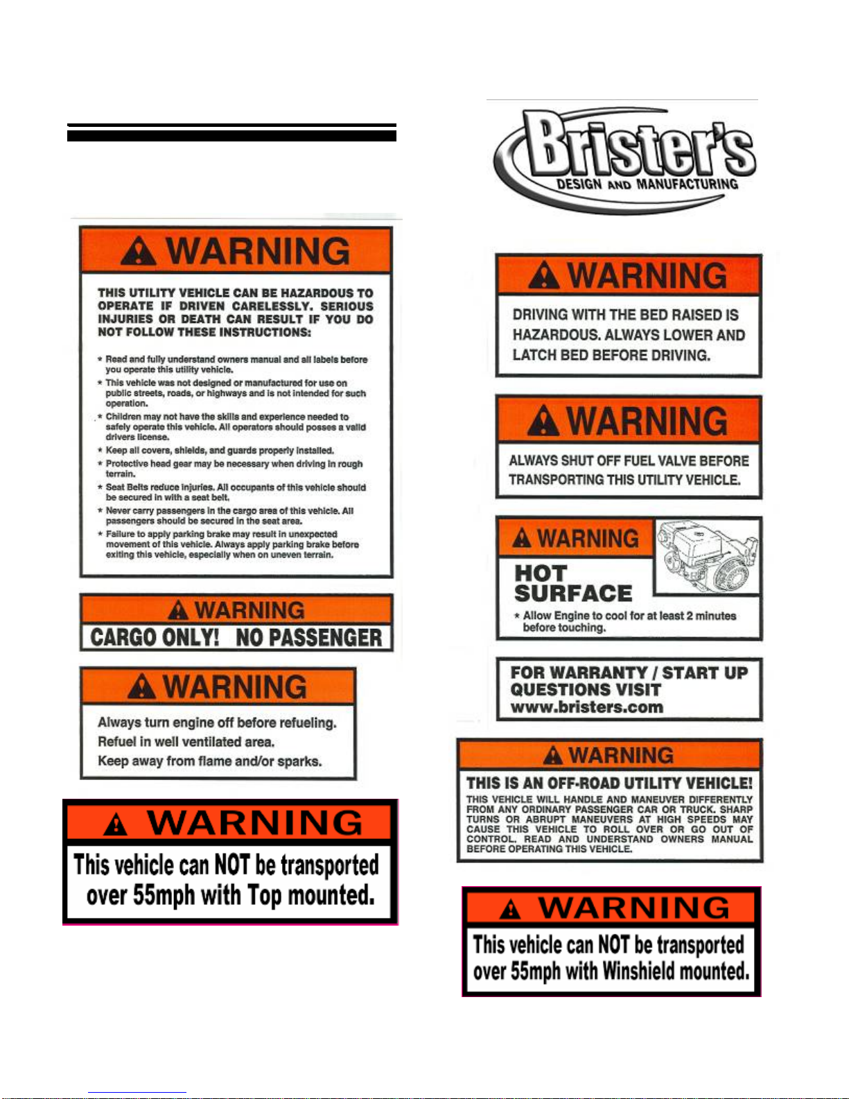
It is very important to read, understand, and follow all
instructions and warnings located on the decals on your
rister Utility Vehicle. B
6
Page 7

Section 2 Safety
Safe Operating Procedures
The safe operation of any machinery is a big c
ll consumers. Your Brister Utility Vehicle has been
a
designed with many built-in safety features. However,
no one sho
ading this Operator’s Manual. Also read all
re
instructions noted on the safety decals.
* Be familiar with all functions of this vehicle.
Keep all bystanders away from this vehicle during
*
operation.
* Do not allow anyone to operate t
ot fully read and comprehended this manual and who
n
has not been properly trained in the safe operation of
this vehicle.
* Do not operate a vehicle with damaged or defective
parts. R
utting vehicle back in to service.
p
* Do not allow any
is vehicle.
th
Operator must always use both hands on the steering
*
wheel.
No riders allowed except in factory designed and
*
supplied seating.
Operate this vehicle from the driver’s seat only.
*
* Do not leave this vehicle unattended
nning.
ru
* Do not dismount a moving
eath could occur.
d
* Always operate vehicle with belt guard installed. Do
not leave pulleys
* Do not touch engine, engine exhaust pipe and/or
muffler while th
* Keep hands, feet, long hair, clothing, and jewelry away
from moving parts and obvious pinch points to avoid
getting caught.
* Wear snug-fitting clothing to avoid entanglement with
moving parts.
uld operate this vehicle before carefully
his vehicle who has
epair all damages and defective parts before
one under 16 years of age to operate
with engine
vehicle as serious injury or
and belts exposed.
ey are hot.
oncern to
* Some conditions may warrant extra safety gear to be
orn such as safety helmets and/or goggles. w
Keep hands, arms, feet and all bodily a* ppendages
safely inside the confines of the vehicle.
Always be aware of and avoi*
that have a potential of hitting and/or poking individuals
riding the vehicle. Serious body harm could result.
* Avoid sudden stops, starts, and turns.
* Always operate your vehicle at a safe speed that w
allow you to maintain control.
* Operator and passenger are responsible for deciding i
their situation warrants using seat belts.
* Do not exceed total payload capacity of this vehicle
* Do not pull a trailer or implement exceeding 1100
ound towing capacity or lossp
Do not attach an implement, trailer or other d*
the hitch that will produce negative tongue weight.
* Follow all towing instructions in this manual when
towing the UTV behind another vehicle. Do not tow
vehicle faster than 25 MPH.
Do not use the vehicle as an anchor devic*
* Beware, tow ropes, cables and chains can break when
ulling another vehicle or op
or death to anyone in line with the whipping action
created when they break. Never jerk when pulling,
lways ease into a pa
tow line. Never be in line with the tow line.
* Reduce speed when loaded with cargo. Heavy car
load takes longer to stop.
* Reduce speed and payload on hilly, rough, wet, slick
r unstable grouo
* Always make turns at a speed that will maintain control
f vehicle. No
peed when turning empty and reduce speed even
s
ever make turns at full speed. Reduce
ull gently. Always stay clear of the
nd.
d tree limbs and brush
of control may result.
e.
bject causing serious injury
ill
.
evice to
go
f
7
Page 8

more when turning loaded with cargo or when pulling a
cargo load. The heaver the cargo load, the slower the
rn should be.
tu
* Make sure
ed down.
ti
* Do not exceed 400 lbs. in cargo bed area, or 900 lb
tal on this vehicle.
to
* Do not mount a receiver hitch type carrier p
e vehicle.
th
* Do not load the Brush Guard Bar with heavy
quipment. Rollover could result from such loading.
e
* The Brush Guard Bar is not ce
rotection System). Always avoid rollovers.
P
* Do not operate this vehicle on highways, public roads,
or where it may be a hazard to faster moving
* Do not operate this vehicle while drinking or under
influence of alcohol and drugs.
* Never attempt wheelies, jumps, or other stunts
drive recklessly. Always operate your vehicle at a s
speed that will allow you to maintain control.
Never use vehicle for racing and never modify the
*
engine to exceed 25 MPH vehicle speed.
* Never modify any parts on the vehicle without
authorization. Unauthorized modifications will void
warranty to all parts di
e modification.
th
* Always make sure the vehicle pathway is clear o
objects when backing up. Know location of
round vehicle and especially location of small children.
a
Take extra precautions when rear view is hindered by
cargo.
Always park on level ground, stop engine, set parking
*
brake and remove ignition key before leaving the
vehicle. Choc
* Use extreme caution when cresting hills or when
visibility is limited. Proceed slowly until yo
conditions immediately ahead are safe.
* Keep front wheels straight when c
ver bumps.
o
* Do not s
oss of control and rollover could result.
L
all gear or cargo is properly secured and
s.
latform to
rtified ROPS (Roll Over
traffic.
the
. Never
afe
rectly and indirectly affected by
f all
personnel
k tires if condition warrants.
u are sure trail
resting hills or going
top, start suddenly or over accelerate on hills.
* Use extreme caution when descending hills or runn
on loose slippery surfaces. Towing, braking, a
apabilities are greatly diminished.
c
* Do not operate vehicle on 15 degree slopes or
teeper.
s
* Avoid changing direction or making sharp steering
corrections on slopes or rollover m
* If this vehicle begins to tip when crossing a slope, turn
the front wheels downhill to regain stability and
When crossing a slope on soft terrain, turn the front
*
wheels slightly uphill and maintain a constant speed to
maintain a straight line of tr
* When descending hills or slopes apply steady
pressure to the foot brake to avoid potential of
freewheeling or runaway.
* Never allow vehicle to coast or
ss of control may result.
lo
* If your vehicle loses power and stops on a hill,
immediately
own the hill maintaining a straight downhill line of
d
travel. Do not attempt to turn the vehicle sideways on
the hill or a rollover could result.
* When traveling at night always use your headligh
and reduce speed according to visibility, trail, and terra
conditions.
Avoid water crossings when possible and never cross
*
a body of water where depth is unknown. Loss of powe
will occur if the drive belt becomes submerged or wet.
Unnecessary crossing of streams an
rodes shore line and damages water-born habitat. If
e
you must cross, do it at a point where banks are not
steep and proceed at a slow and steady speed.
* Front bumper and brush guards are not
usher bars. Do not attempt to push other vehicles or
p
implements or damage may result.
When refueling use an (UL) approved non-metallic
*
container that has no screen or filter. Se
n the ground before fueling to eliminate static
o
discharge and do not use Methanol fuel.
* Do not smoke or use e
hones while refueling.
p
* Always maintain proper tire inflation.
engage the foot brake and back slowly
avel.
lectrical devices including cell
ay occur.
free wheel in neutral or
d waterways
nd tractive
designed as
t the container
ing
control.
ts
in
r
8
Page 9

* Always disconnect the negative battery terminal befo
making a
elding on this vehicle.
w
* Battery fumes are explosive. A spark will ignite battery
fumes. Wear a face shield when charging or jump
battery. Follow all battery safety rules outline
anual.
m
* Avoid battery acid spills. Do not get battery acid on
eyes, face, or other body parts. Flush eyes and other
body parts immediately with water for
inutes if battery acid has gotten on them.
m
* Always check wheel lug nut torque values two hours
fter initial operation and two hours after each tire repair
a
and/or replacement. Routinely check lug nut torqu
valves every 100 hours of operation.
* Support this vehicle securely before working beneath.
Chock the wheels to prevent the vehicle from rolli
* Do not shift transaxle unless this vehicle is fully
stopped and the engine is at idle or damage may occur.
Each vehi
y the Dealer. Listed below is an example of the
b
checklist that is included w
that is to be submitted to Brister’s upon Retail Sale. The
Pre-Delivery Certificate and Warranty Registration mu
be submitted to Brister’s in order to activate the vehicle
warranty.
djustments to the vehicle electrical system or
d in this
at least 15
cle must undergo a Pre-Delivery Inspection
ith the Warranty Registration
re
ing a
e
ng.
st
Pre-Delivery Steps
The dealer is required to complet
efore customer may take possession of the vehicle.
b
This information must be filled in and check list checke
off or initialed by individuals p
ealership’s name, signatures of individuals filling in the
D
form, seller’s signature, custome
signing dates are also required.
Below is a list of the information that q
ompleted and checked off. c
ehicle Information
V
Model No. _______ __
Date ___________
al No. ___________ Seri
Engine Serial No.
e “Pre-Delivery” steps
d
erforming the checks.
r’s signature, and
is re uired to be
__
ealer Service and Inspection List
D
__
Fully charge battery. Check battery voltage to verify
hat it is fullyt
__ Check fuel valve lever to make sure it is in the
correct position.
__ Check tire pressure to make sure front and rear tires
have 6 psi.
_ Make sure wheel lug bol_
Newton meters (65ft.lbs).
__ Check engine oil leve
10W30 oil if oil is below the full m
*this should be done with seat (a
Tray if equipped) removed
_ Che_
specification if needed.
__ Check tie rods for tigh
__ Check Choke Control. It should move and return
reely. f
_d_ Step on foot brake to make sure the peda
oes not go to the floor.
__ Make sure seats and
to the frame.
_ Make sure all safety decals are in pla_
__ Check headlights to make sure they are working
are properly mounted.
__ Inspect air cleaner element. Make certain it is clean
and in place.
__ Inspect the fuel tank to make sure it is properly
installed and that there are no leaks.
__ Check fuel level to make sure there is at least 1/8 of
a tank of gas prior to performing initial starting
operations.
__ Inspect fuel lines to make sure they are properly
installed and that there are no leaks.
_ Check steering by exe_
each direction.
__ Check parking brake to ma
old and release.
h
charged.
ts/nuts are tightened to 90
l at the dipstick. Add SAE
ark on the dipstick.
nd under seat storage
ck engine for correct RPM. Set to factory
tness.
l is firm and
seat belts are properly fastened
ce.
and
cuting a full lock to lock turn in
ke sure it will engage,
9
Page 10
__ Check throttle control to make sure it moves and
returns freely.
__ Check differential oil level at the differential oil plug.
Add 30 weight oil if oil is low.
_ Check overall appearance for
_
body and molding damage.
ealer Test Ride List
D
__ Check engine for starting, accelerating, runni
smooth, and idling smoothly.
__ Check steering response. There should be no free
play.
__ Check forward, neutral, and reverse shifting
sponse. Also check neutral start response.
re
__ Chec
nd disengages.
a
_ Make sure throttle is responsive and returns freely.
_
__ Make sure the suspen
table.
s
__ Make su
__Make sure the foot brake has a firm enga
that stopping is straight.
__ Make sure there are no abnormal rattles or
vibrations.
k parking brake to make sure it engages, holds,
sion ride is satisfactorily and
re there are no fuel or petroleum leaks.
cleanliness and for
ng
gement and
Dealer Delivery to Customer List
__ Warranty regis
__ Owner’s Manual has been delivered to and reviewe
by the customer.
__ Engine Manual has been delivered to and reviewed
by the custo
__Warranty Policy limits and requirements have been
explained to the c
__ Location and functions of vehicle controls have been
explained.
_ Fuel transportation and storage procedures have
_
been explained.
__ Transportation of utility vehicle is limited to 55mph,
hen equipped with top and windshield w
tration form is complete.
d
mer.
ustomer.
__ Fluid fill and lubrication points have been located and
explained to the customer.
__ Information on the safety decals have been reviewed
with the customer.
Customer Acceptance List
Customer initials required where accepted as
successfully completed.
__ Customer has reviewed and understood warranty
policy (ies).
__ Customer has inspected the vehicle and it meets
customer satisfaction.
__ Customer understands the importance of following
the owner’s manual instructions.
* IMPORTANT NOTICE *
WHEN TRANSPORTING ANY
BRISTER UTILITY VEHICLE
WITH A WINDSHEILD OR COLOR MATCHED
TOP DO NOT EXCEED 55MPH
Brister’s Design & Manufacturing Co. LLC
Toll Free PH: 1-866-646-5278
Fax: 1-866-329-5278
www.bristers.com
10
Page 11
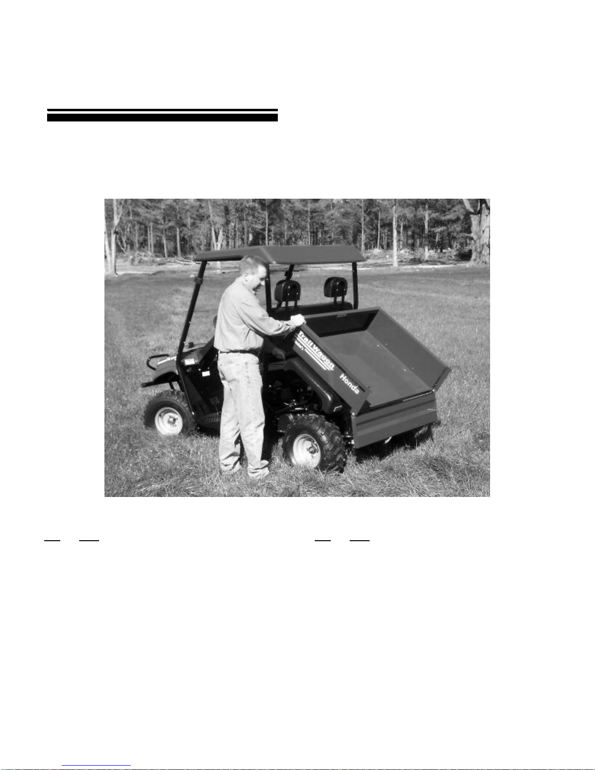
Section 3 Assembly Instructions
Brister Utility Vehicle Utility Vehicle
Assembly Instructions
Your new Brister Utility Vehicle Utility vehicle should include the f
Qty Item
1 #8 black screw (steering cap)
3 ¼” x 1 ¾” Hex head bolts
7 ¼” nylock nuts
4 ¼” x ¾” carriage bolts
4 ¼” flat washers
8 5/16” x 2” socket head bolts
12 5/16” curved washers
10 5/16” nylock nuts
4 5/16” x 2” hex head bolts
2 5/16” center lock nuts
ollowing items to be assembled:
Qty Item
2 5/8” x 4” Hex bolt
2 5/8” nylock nuts
1 set of keys
1 Steering wheel (with cap)
1 Bumper
2 Rear fenders
2 Rear frame stubs
1 Seat back
1 Cage
1 Cargo Bed with tailgate
11
Page 12
Section 3 Assembly Instructions
Pre-Assembly Instructions
1) wner’s Manual.
Read O
2) Unpack all vehicle a
have everything list
3) If y u
Seat / Brushguard Assembly
o have any questions or problems with your
Brister's Design & Manufacturing Co. LLC product
please call us, 66-646-5278.
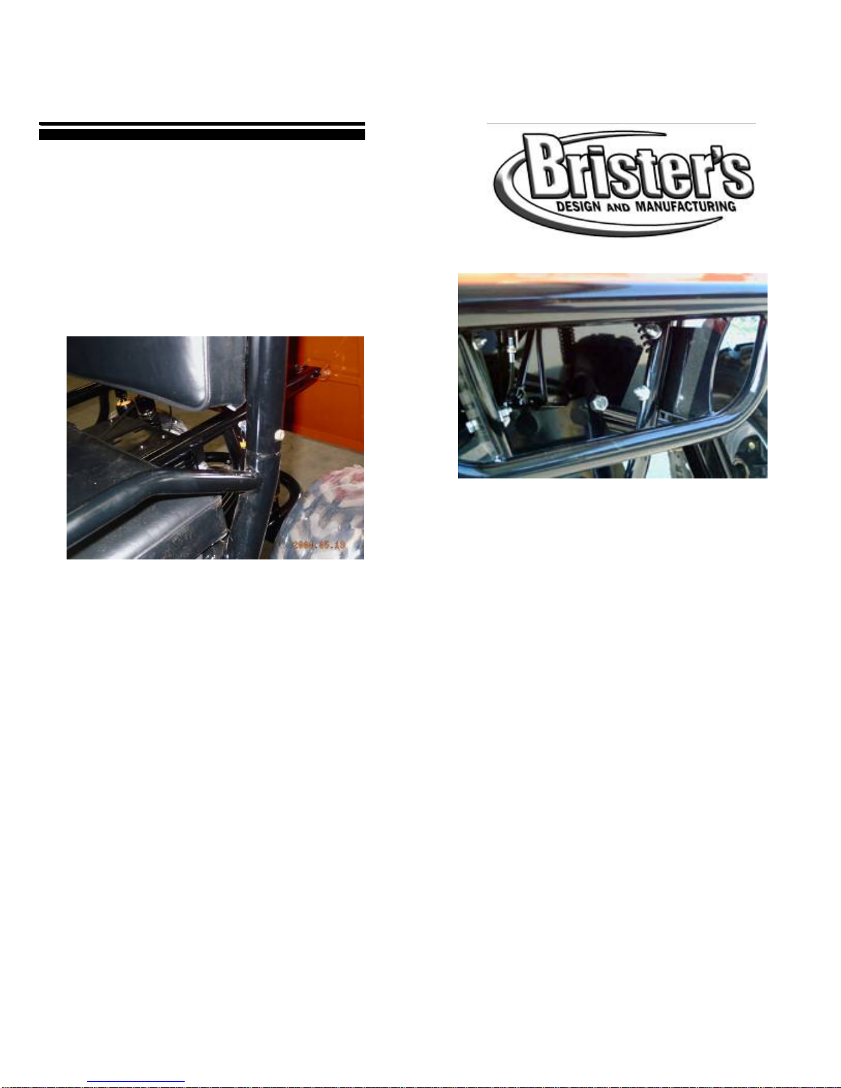
1) Place seat back frame on vehicle frame tubes.
Insert a 5/16” x 2” socket head bolt through
both bottom joints. The head of the bolt should
be on the outside of the vehicle. Put a curved
washer on the threaded end of the bolt. Place
a 5/16” nylock nut on the bolts but do not
tighten.
2) Place the cage on front vehicle frame tubes
and seat back. Insert a 5/16” x 2” socket head
bolt through all four joints. The head of the
bolt should be on the outside of the vehicle.
Put a curved washer on the threaded end of
the bolt. Place a 5/16” nylock nut on the bolts.
Tighten all 6 nuts (including step 3).
nd assembly parts. Make sure you
ed on the previous page.
toll free 1-8
Bumper Installation
Steering Wheel Installation
1) Align the holes in the front bumper with the
mounting holes in the front frame tubes. Insert
the four 5/16” x 2” bolts through the bumper
bracket and then into the frame tubes. Put a
curved washer on the threaded end of the bolt.
Place a 5/16” nylock nut on the bolts and
tighten.
1) Remove the plastic steering column cover by
removing the 3 screws on the bottom with a
5/16” socket. If equipped with top and bottom
steering column covers
2) Turn vehicle steering so that it is pointed
straight forward. Line up holes in steering
wheel with mounting holes so that the center
spoke is pointing down. Install ¼” x 1 ¾” hex
head bolts from the back. Tighten with ¼”
nylock nuts.
3) Install steering cap with #8 black screw.
4) Re-install steering column cover.
12
Page 13
Cargo Bed Installation
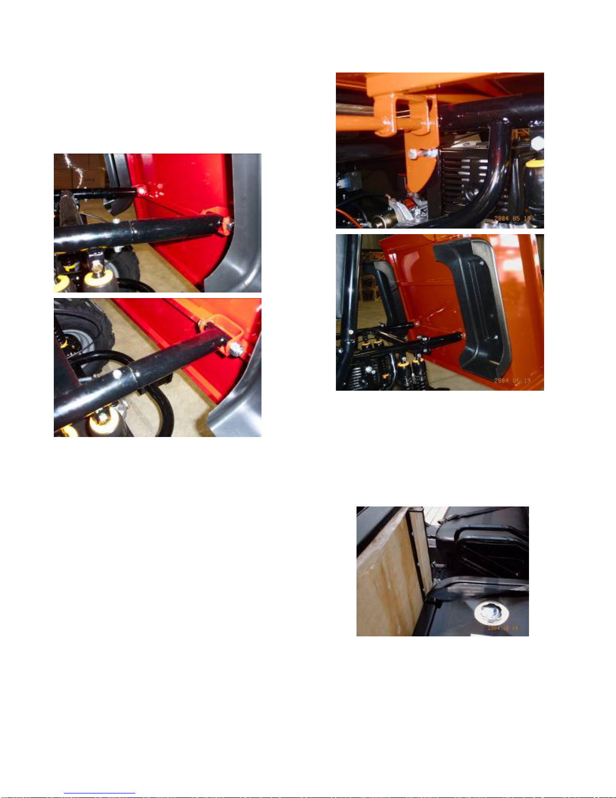
1) Locate rear frame stubs at the rear of frame.
The bed pivot tube on the stub should be at
the top. Insert 5/16” x 2” socket head bolt.
Loosely install 5/16” center lock nut (do not
tighten until after cargo bed is installed)
2) Place the cargo bed on the vehicle and insert a
5/8” x 4” hex head bolt through each pivot
bracket and frame stub tube.
3) Tighten both 5/16” frame stub bolts and nuts.
4) Install the 5/8” nylock nuts on the pivot bolts.
Tighten the pivots and then loosen ¼ turn.
5) Loosen the bed latch pin bolt on the frame just
enough for it to slide in the adjustment slot.
(shown in upper right photo)
6) Close the bed and position the latch pin bolt so
that it is at the bottom of the latch slot
prevent rattles. Tighten the latch pin.
to
7) Fenders installation (if Equipped, no fenders
on TW265) Tilt the cargo bed up. Line up the
holes in the rear fenders with the square holes
in the bed. The raised rectangular surface on
the fender should be completely hidden under
the bed. If not, turn the fender around. Insert
a ¼” x ¾” carriage bolt through the bed and
into the fender. Fasten with a ¼” flat washer
and a ¼” nylock.
Sea a
t B se Installation
1) Pl ed to seat base under front seat
ace tabs attach
frame bar (if equipped into slots in plastic tray), fold
seat base into position. (if equipped The rear tabs
sh
ould fall into the slots in the rear of the plastic
tray)
13
Page 14

Sec oti n 4 Operating Instructions
General Operation
Start your Brister Utility Vehicle by following the starting
procedures as noted below.
1. Depress brake pedal with your foot and hold.
Pull firmly up on the park brake lever with your
hand until the lever is tight.
2. Place gearshift in neutral
3. Apply choke fully when engine is cold.
4.
Turn ignition key fully clockwise and hold to stop
engine.
5. Release ignition key to run position and chok
engine starts.
Driving is as
transmission. A simple forward and reverse shifter
provides direction control.
Just turn the key and the 12 volt electric starter provides
safe and easy starting. There is a manual choke control
below the seat for quick cold weather starting. A back-up
pull-rope s
the battery down. The
drive system means there i
into either forward or reverse when the
stopped and press the throttle pedal to
while the vehicle is moving.
pedal that is located on the floorboard left of the
accelerator. A lever action parking brake control is
mounted o
operator and passenger seats. Depress the button on
the park brake control lever to release the park brake.
to normal operating position immediately after
6 Turn ignition key counterclockwise to stop
engine.
easy as driving a car with an automatic
tarter mechanism is provided on the engine
st in case y ju
ing is accomplished by simply depressing the brake
rakB
ou accidentally leave the key on and run
n the center console located between the
e
infinitely variable torque converter
s no clutching. You just shift
vehicle is
go. Never shift
Pre-Start Check List
__
Check tire pressure as indicated.
__ Make sure wheel lug bolts/nuts are tightened to 65ft.
s.
lb
_ All nuts, bolts, screws, and fasteners should be
_
cked.
che
_ Turn on headlights to make sure battery has a charge
_
nd electrical lighting circuit is working.
a
_ Check tail lights and brake lights. (if applicable)
_
_ Check park brake to make sure it will engage, hold
_
nd release.
a
_ Check steering by executing a full lock to lock turn in
_
each direction.
__ Check engine oil level at the dipstick. Add oil as
indicated.
_ Check differential oil level at the differential oil plug._
Add gear lube as indicated.
__ Check fuel valve lever position. Valve lever
ff except when running the engine. o
__ Check fuel level to make sure there is at least 1/8 of a
tank of gas prior to performing initial starting operations.
should be
14
Page 15
Section 5 Maintenance
Fuel Type
The fuel tank is located under seat.
TW11, TW 413, CW11, CW413 Fuel Capacity
W-265 & TW265 Fuel capacity is 6.1 Liters
C
hen filling the fuel tank, place the gear shift in forward
W
or reverse, set the park b
move ignition key. Clean dirt from around the fuel tank
re
cap, remove cap, and begin filling. When f
e cap back on securely and wipe up any spilled
th
gasoline. Use regular unle
ting of 87 or higher.
ra
IMPORTANT:
containing methanol, or gasohol containing more than
10% ethanol because the
damaged. Do NOT mix oil with gasoline.
Using a fuel stabilizer/conditioner in the vehicle can
provide benefits such as:
* Keeps gasoline fresh during storage of 90 days or less.
For longer storage, drain the fuel tank.
* Cleans the engine during operation.
* Eliminates gum-like
dd the correct amount of gas stabilizer/conditioner to
A
the gas. Follow the gas stabilizer/conditioner
manufacturer’ st results.
See engine o ual for the following:
* Draining the
Checkin*
Engine fuel valve lever.
*
g fuel line for cracks and leaks.
Never use metha
s directions for be
perator’s man
fuel tank.
rake, turn off the engine, and
aded gasoline with an octane
nol, gasoline
fuel system could be
varnish build-up in the fuel system.
is 5 Gal.
inished, screw
Engine Maintenance
General Information
Detailed instructions and recommendations for break-in
and regular maintenance are specified in the engine
operator’s manual. Engine warranty is backed by the
engine manufacturer. Please refer to engine
manufacturer’s manual for engine servicing, lubricating
oil levels, oil quality and viscosity recommendations, bolt
orques, etc. Specialt
pplicable data that is not duplicated here.
a
attention should be paid to
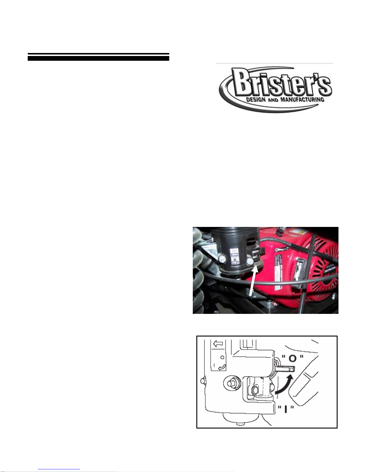
Engine Fuel Valve Lever
fer to Figure 5-1
Re
The engine fuel valve opens and
tween the fuel tank and carburetor. Leave fuel valve
be
lever in the OFF position when the engine is not i
to prevent carburetor flooding and reduce possibility of
fuel leakage into the cylinder cavity and engine oil
reservoir. Turn fuel valve lever to the ON position when
running the engine.
closes the passage
n use
FUEL VALVE
Figure 5-1
15
Page 16
Section 5 Maintenance
*
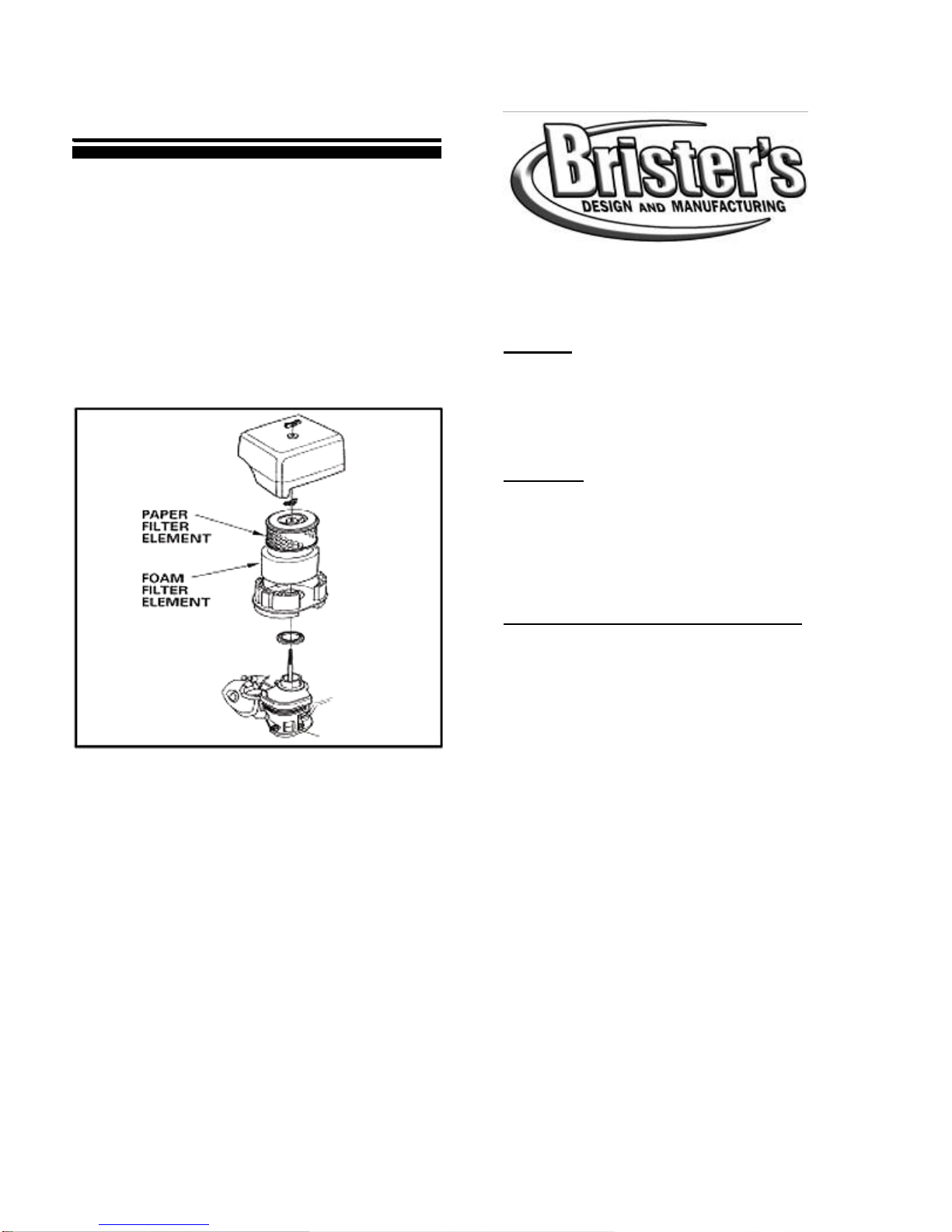
Foam element –
detergent in warm water or in a nonflammable solvent.
Do not wring element. Squeeze excess cleaning fluids
out. Allow time for the element to dry and then soak it
ith clean engine oil. Squeeze excess oil out. Excess oil
w
ft in the filter will cause engine to smoke briefly when
le
rst started.
fi
efore installing the filter elements to make sure they
B
have not be
engine without the filters installed.
Figure 5-2
en damaged during cleaning. Never run an
Clean foam element with
Spark Plugs
HONDA
NGK BPR6ES
CHAMPION RN9YC
UTOLITE 4263 / 63
A
DENSO W20EPR-U
UBARU
S
NGK BR6HS
HAMPION C
RLH6C
Air Filter Elements Replacement Parts
Description Part No.
Honda
Paper Filter Element 17210-ZE3-000
Honda
Foam Filter Element 17210-ZE3
Refer to Figure 5-2
Subaru
Paper & Foam Element (265cc) 279-32607-07
Fuel Hose –
leaks or other dama
amage is suspected.
d
Inspect fuel hos
ge. Replace immediately if any
e monthly for cracks,
-010
16
Page 17
Section 5 Maintenance
Engine Oil
A general description for engine oil maintenance,
recommendations, and capacities is provided below
See Eng. ine Operator’s Manual for a detailed description.
Note:
eng
Running engine low on oil can cause
ine damage and void engine warranty.
Note:
Overf
power, engine damage and void engine warranty.
Engin
Ref
REMOV
EAS
* Filler c
* Drain plug location: At rear end of engine
S
*
* Subaru Engine Oil Capacity: 1.1 US qts. / 1.0 liters
* Quantity: Fill oil to outer edge of oil fill hole.
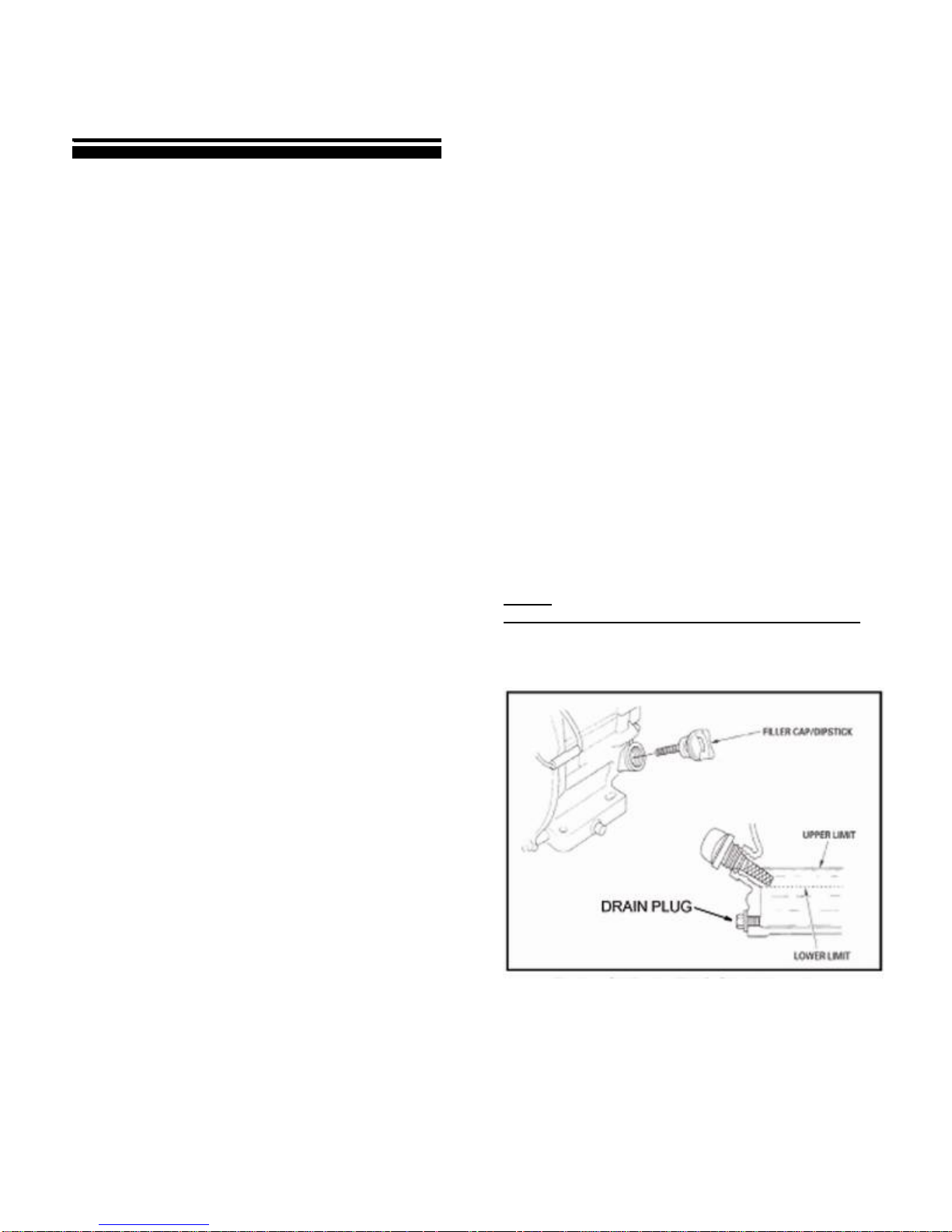
e Oil Fill and Drain Locations
er to Figure 5-4
Y ACCESS
Type of Lubrication: SAE 30, with API classification*
J, SL or Equivalent
Honda Engine Oil Capacity: 1.16 US qts. /1.1 liters
illing of oil level can cause loss of
E SEAT (and plastic tray if equipped) FOR
ap/dipstick location: At front end of engine
of
Engine Oil Maintenance Schedule
* Check oil level after each use.
* Make first oil change after the first month of operation
or at 20 hours of operation (whichever comes first).
* Make all subsequent oil changes every 6 months or
every 100 hours of operation (whichever comes first).
Engine Oil Level Check
Refer to Figure 5-4
Check engine oil daily with filler cap/dipstick located at
the engine rear end as follows:
1. Park Vehicle on a level surface, set park brake,
turn off ignition switch, and remove switch key.
2. Remove filler cap/dipstick and wipe it clean.
3. Insert and remove dipstick without screwing it
into the fill neck. Check oil level shown on
dipstick.
4. Fill to edge of oil fill hole with recommended oil
when oil levels are low.
5. Replace filler cap/dipstick and tighten secure
ly.
Engine Oil Change
Warms oil drains quickly and completely. T
rain used engine oil while engine is still warm as
d
llows:
fo
1. Park vehicle
turn off ignition switch, and remove switch key.
2. Place a suitable container below engine to ca
used oil. Remove filler cap/dipstick and drain
plug.
3. Allow used oil to drain completely
reinstall and tighten drain plug securely.
4. Dispose of used motor oil in a manner th
compatible with the environment. Do not throw
used oil in the trash. Do not pour it on the
ground, or down a drain.
5. Fill oil to the outer edge of the oil fill hole with
recommended oil. Engine must be level when
filling.
6. Replace filler cap/dipstick and tighten securely.
NOTE:
TO DRAIN OIL REMOVE REAR OIL DRAIN PLUG
herefore,
on a level surface, set park brake,
and then
at is
Engine Oil Drain, Fill & Check Locations
Figure 5-4
tch
17
Page 18
Section 5 Maintenance
Transaxle Oil
A general description for transaxle oil maintenance,
recomm
NOTE:
damage transaxle a
Transaxle
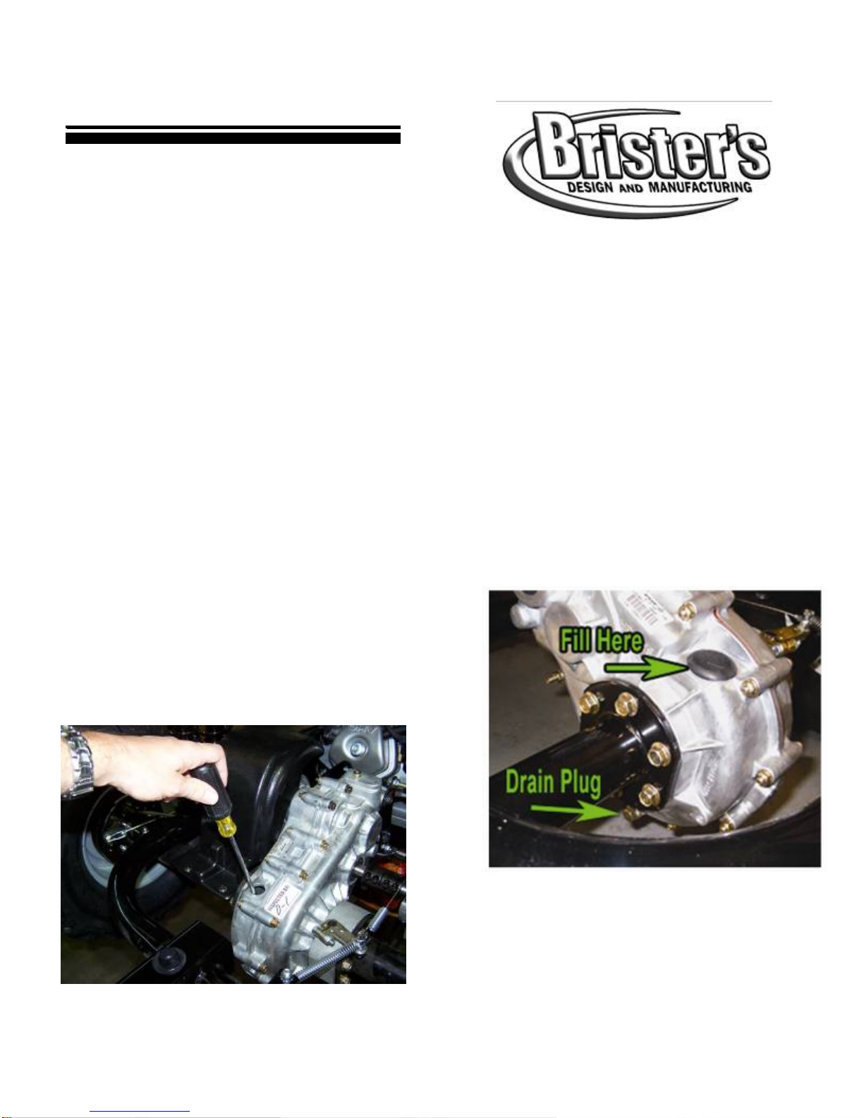
Ref
* Fil p
* Dr
* Ty o
* Transa
Transa
* Ch
leakage
* Check l every 6 months or every 200
hou w
This ccomplished by Parking vehicle on a level
surf ce, set park brake, turn off ignition switch, and
remove switch key, using a clean long bladed screw
driv r hole until it
touch e the screw
driver.
il visibo
*
(w
endations, and capacities is provided below.
Running vehicle low on transa
nd void warranty.
xle oil can
Oil Type, Fill, and Drain
er to Figure 5-5
l ca location: At rear left hand side (See arrow)
ain plug location: At bottom center of transaxle.
pe f Lubrication: SAE 30W oil.
xle Lubrication Capacity: 20 oz.
xle Oil Maintenance Schedule
eck transaxle housing for damage and possible oil
after each use.
transaxle oil leve
rs ( hichever comes first).
can be a
a
er (or similar object) insert into fille
es the bottom of gear case. Remov
There should be approximately 2.1/4” to 2.1/2” of
le on screw driver. Refer to Figure 5-5A
Change transaxle oil once a year or every 600 hours
hichever comes first).
Figure 5-5A
Transaxle Oil Change
Refer to Figure 5-5B
Warm oil drains quickly and completely. Therefore, drain
used transaxle oil while transaxle housing is still warm
as follows:
. Park vehicle on a level surface, set park brake,
1
turn off ignition switch, and remove switch key.
. Place a suitable container below the transfer
2
case to catch used oil. Remove fill cap and drain
plug.
. Allow used oil to drain completely and then
3
reinstall drain plug and tighten it securely.
4. Dispose of used
that is compatible with the environ
throw used oil in the trash, pour it on the ground,
or down a drain.
5. Fill transaxle housing with 20 oz. SAE 30W oil.
6. Replace fill cap and tighten securely.
Figure 5-5B
transaxle case oil in a manner
ment. Do not
18
Page 19
Section 5 Maintenance
Drive Belt
The dive belt is considered a wearable item.
Replacement intervals depend on vehicle use and
environment. If your belt is slipping you may need to
replace it.
1. P brake,
ark vehicle on a level surface, set park
place shifter in Neutral, turn off ignition switch,
and remove switch key.
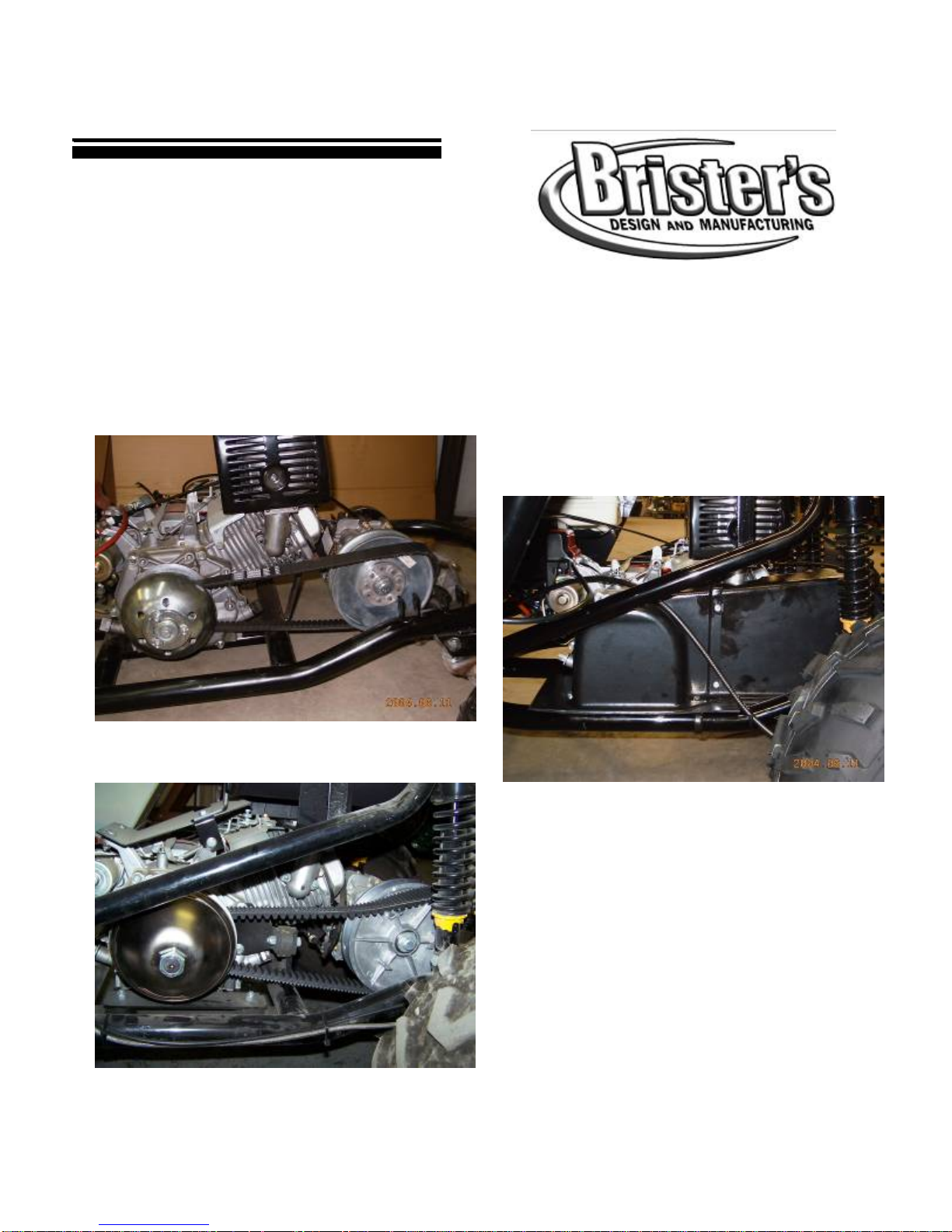
2. Remove the upper belt covers. (It is not
necessary to remove the bot
3. “Walk” the belt off of the rear pulley as sh
Figure 5-6.
tom cover.
own in
4. Install the new belt on the front pulley first and
“walk” it onto the rear pulley.
5. Reinstall the belt guards. Figure 5-7.
Attention: Failure to reinstall the belt gua
void your warranty.
rds may
Figure 5-6
Figure 5-7
19
Page 20
Section 6 Troubleshooting
Fuel in the Cylinder Cavity
In the event that the fuel valve is left open while
tran o ter Utility Vehicle it is
sp rting or towing this Bris
pos e cylinder
sible that fuel has leaked down into th
cav l not start. With
I lity. f this has occurred the engine wi
the in will feel like it
has “l per steps to follow if
ocked pro up”. Below are the
your Brister ine seems to have fuel in
the cylinde
Utility Vehicle eng
r cavity.
gine cyl der cavity full of fuel the en
Use EXTREME CAUTION when
performing the activity below.
Gasoline is EXTREMELY FLAMABLE!
1. Move the vehicle to a well ventilated area, awa
from sparks or flame.
2. Pa
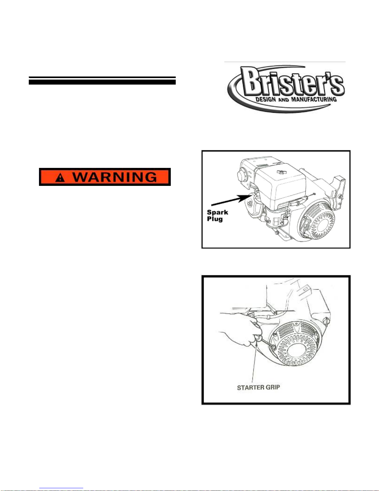
3. Next, remove the wire connected to the spar
4. WARNING: Stand away from the spark plug
5.
6. epeat step 3 until only air escapes out of the
7. roperly replace the spark plug back into the
8. Connect the plug wire. Your Brister Utility
rk Vehicle on a level surface, set park brake,
turn off ignition switch, and remove switch key.
k
plug. And remove the spark plug from the
engine. (See Figure 6-1) (Spark Plug Wren
supplied with Operator’s Manual)
hole when performing step 5. Fuel can sp
several feet.
Wearing eye protection, slowly pull the recoil
start grip handle (See Figure 6-2) in an upward
motion. This should force the fuel out of the
cylinder cavity through the spark plug hole.
aution: This gasoline spraying out of the
C
ylinder cavity is very flammable, use extreme
c
aution and make sure there are no sparks or
c
ames nearby.
fl
R
park plug hole.
s
P
cylinde
s
allow for it to evaporate before continuing.
Vehicle is now ready to start.
r head, move the vehicle away from any
pilled fuel. If there is fuel on the vehicle itself,
ch
ray
www.bristers.com
y
Figure 6-1
Figure 6-2
20
Page 21
Supp
lement:
Brister 4x4 Utility Vehicle
CW-413, T
This tional features,
supplement covers the addi
ope e Brister Utility Vehicle
ration and maintenance of th
4x4
Fe
atures
• 13 hp, 390cc Honda engin e
• Electric 4x4 selection
• Auto-Locking front differential
• Manual locking rear differential
• 4 wheel hydraulic brakes
o Front disk
o Rear drum
• Long travel strut front suspension
peration of Four Wheel Drive
O
eatures
F
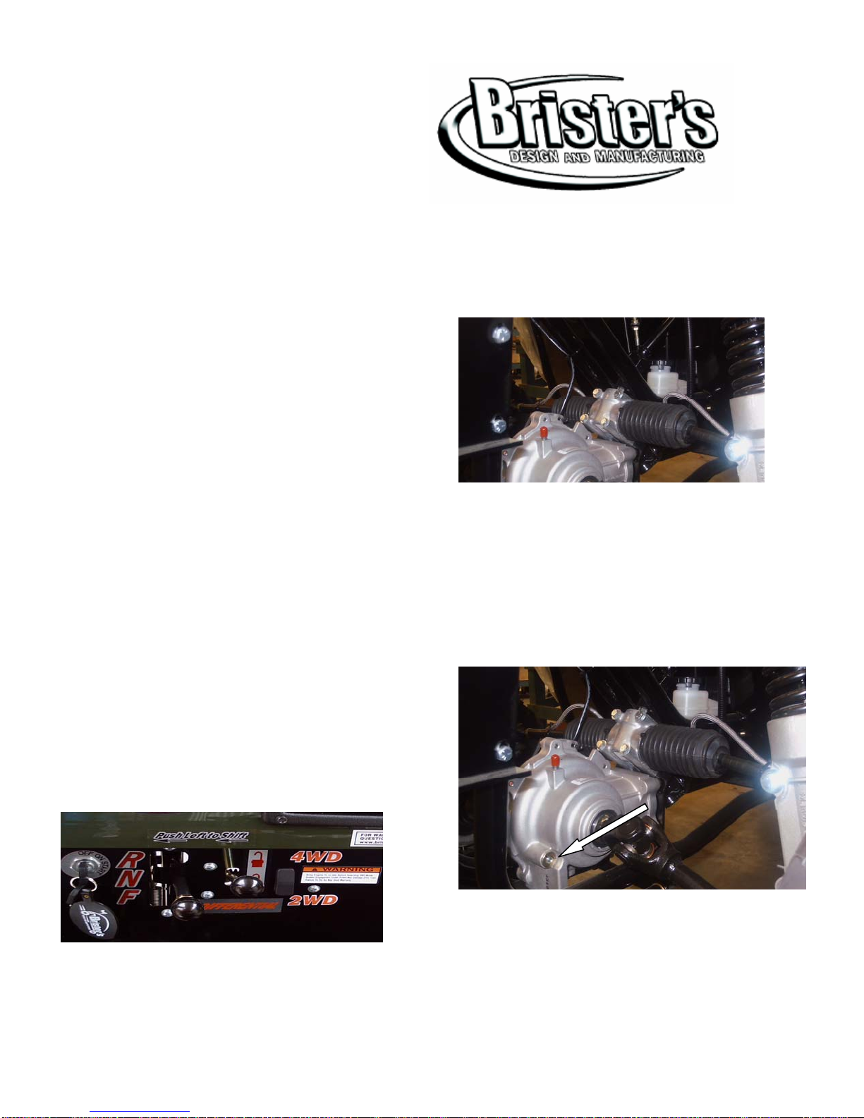
he rear axle is equipped with a manually operated
T
differential lo
ifferential lever to the left and down. Locking the
d
ifferential sends equal power to both rear wheels for
d
etter traction. It may be used in both 2WD and 4WD
b
odes.
m
ote: Locking the differential on paved or hard
N
urfaces may increase steering effort and tire wear.
s
To switch to four wheel drive, the front wheels are
engaged simply by flipping the dashboard switch to
4WD. In 4WD mode power is automatically sent to the
front wheels when the rear wheels lose traction.
Because the power transfer is automatic, you may
operate the vehicle in 4WD mode continuously without
affecting steering effort or tire wear.
ck. It is engaged (locked) by moving the
Warning: Bring engine to an idle before
selecting 4WD mode. Sudden engagement of
4X4 switch under power may damage drive
train. Failure to do so may void warranty.
W-413
Maint
Hyd
pressur
Bef d
level in the reservoir. The reservoir is located under
the hood behi
the MAX line with DO
If you notice that the brake pedal feels spongy or the
vehicle is not stopping well, take the vehicle to a
qualified service center.
Front Differential Gear Box – It is recommended that
the oil be changed once every 2000 miles (about 150
to 200 hours). To change the oil, follow each step on
the procedure listed below.
enance
raulic Brakes – Hydraulic Brakes use fluid
e to transfer the braking force to the wheels.
ore riving the vehicle each day, check the fluid
nd the front differential gear box. Fill to
T 3 brake fluid.
Gear Box
Oil fill
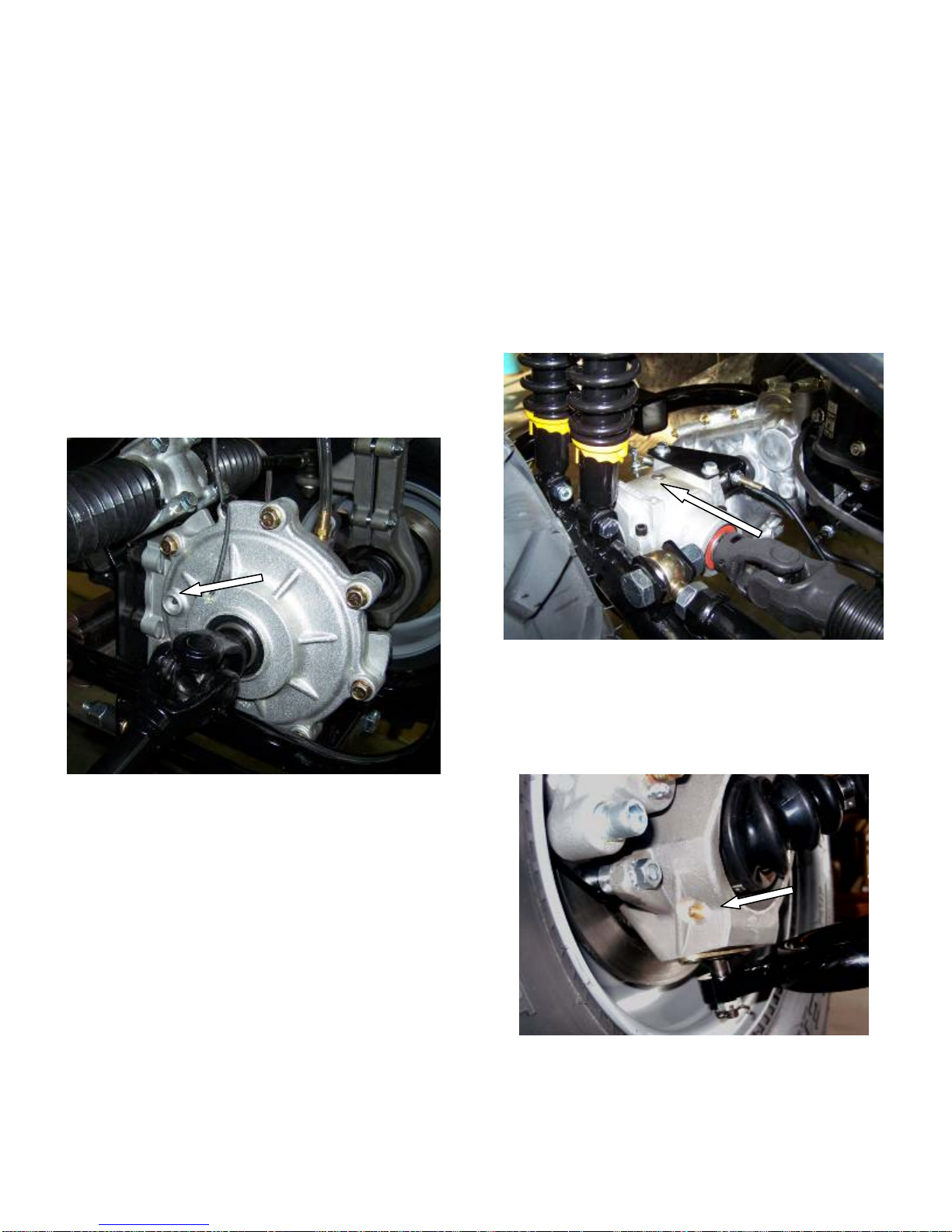
1. Remove the oil drain pl
bottom of the gear case using a 7/16” socket.
2. Let all the oil drain out of the unit. Catch and
discard the oil properly.
3. Be sure to clean off any debris on the drain
plug and reinst
all using a new nylon washer
ug located on the
21
Page 22
(part #20843). Torque the oil drain plug to 9
ft*lbs.
Remove
4.
wrench.
5. Add 150 ml. (5 oz.) of Mobil fluid 424
Brister’s part # 20848 (note: do not use any
other type of oil in this system or the 4WD
will not
6. Reasse
and torque to 10 ft*lbs.
Gear Spacing adjustment
1. Locate set screw on front gear box.
the oil fill plug using a 5/16” hex key
operate properly!)
mble the oil fill plug into the gearcase
1. Remove the oil drain plug located on the
bottom of the gearcase using a ¼” hex key
nch.
wre
2. Let all the oil drain o
discard the oil properly.
3. Be sure to clean off any debris on the dr
plug and reinstall. Torque oil drain plug to 10
ft*lbs.
4. Remove the oil fill plug using a ¼” hex key
wrench.
5. Add 200 ml. (7 oz.) of 80W90 gear oil.
6. Reassemble the
and torque to 10
ut of the unit. Catch and
ain
oil fill plug into the gearcase
ft*lbs.
2. Turn clockwise until you feel re
3. Turn back counter clockwise ¼ turn.
Rear Tr
the oil b
page 18
ansaxle Gear Box – It is recommended that
e changed once a year or after 600 hours. See
of owner’s manual.
Gear
Spacing
Adjusting
Screw
sistance.
Transfer
Gear Box
Oil fill
Strut ball joint lube – It is recommended that the
lower strut ball joint be lubricated every 3 months or
after driving in water, mud or dusty conditions. The
t. grease fitting is located on the back side of the stru
(see photo)
Grease
fitting
90˚
Transfer Gear Box – It is recommended that the
oil be ch
anged once a year or after 600 hours.
22
Page 23

Brister’s Utility Vehicle
Shifter Trouble Shooting
Notice: Always check transmission oil level. Dip a clean screwdriver straight down in the fill hole
to t
he bottom of the gear case. There should be about 2 ½ inches of oil on the screw diver. If oil
nee
ds to be added, use SAE 30 motor oil. See Page 19 for Instructions
• Engine will not turn over when key is turned to start. – This vehicle is equipped with a safe
switch that only allows starting in neutral.
Go to Neutral switch diagnostic procedure.
Gears grind when going into a gear or vehicle stays in gear when shifted to neutral. –
•
Cables need to be lubricated or adjusted.
Go to Cable adjustment procedure.
Neutral switch diagnostic procedure
If starter does not engage when shift lever is in neutral:
1. Apply the parking brake.
2. Turn and hold the key to start. – “Jiggle” the shift lever in the neutral slot. If the starter
engages, release the key and call Brandon at Brister’s Customer service to order a neutral
switch shim kit.
3. If the starter did not engage in step 2, turn and hold the key to start – slowly move the shift
lever from neutral to reverse – if the starter engages, release the key. Repeat, moving the
shift lever from neutral to forward.
• If the starter did engage, go to Cable adjustment procedure section.
• If the starter did not engage call Customer Service at 1-866-646-5278.
Cable adjustment procedure
tiff or sticking cables can cause the vehicle to not shift properly and it may affect starting since the
S
ehicle must go to neutral to start. Before attempting to adjust the cables there are several steps
v
at can be taken to insure the cables are operating properly.
th
• Lubricate the cables. Behind the dash board there are two cables attached to the gear
selector lever. Slide the rubber dust caps up the cable. Drip or spray a penetrating oil into
the cable housing while working the lever. Do
housing. Test the vehicle. If this did not help move t
• Remove the center console (with cup holders). Find the shifter cables and cut the plastic
ties that fasten them to the fr
Replace cable ties but leave them loose so that the cable can move
vehicle. If it is still not performing correctly, move to the adjustmen
ame tube. Over tight cable ties can cause the cable to bind.
this several times as the oil soaks into the
o the next step.
in them. Test the
t procedures that follow.
ty
23
Page 24
Veh
icles with serial number less than 17063.
(See brass tag near top of left rear shock absorber)
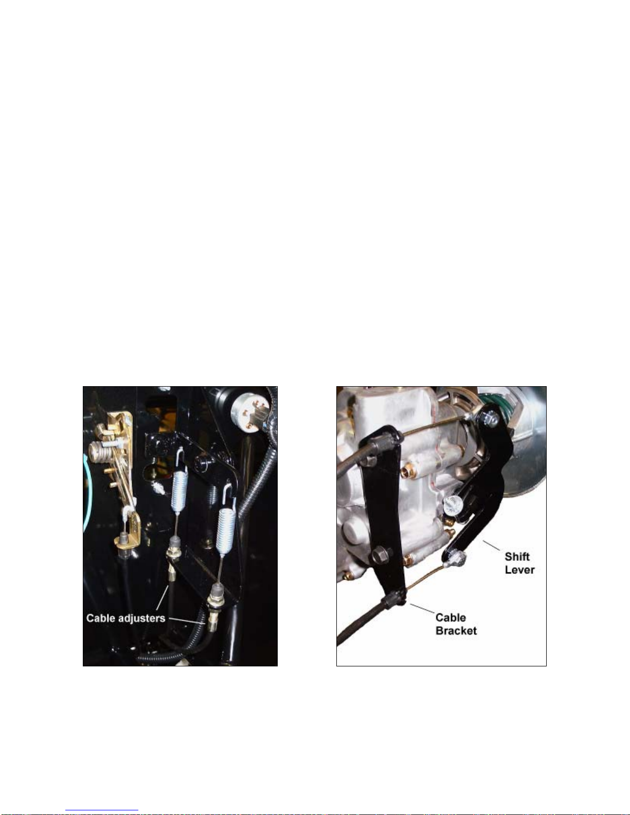
1. n the cable adjusters behind the dash board. (photo on left)
Loose
2. Place the selector lever on the dashboard in forward.
3. Make sure the transmission is fully engaged in forward. The top of the shift lever on the
transmission should be toward the passenger side. You may have to roll the rear wheels a
little until it clicks in.
. Pull the slack out of the forward most cable under the dash (but do not stretch the spring)
4
and tighten the adjuster nuts.
5. Place the selector lever on the dashboard in reverse.
6. Make sure the transmission is fully engaged in reverse. The top of the shift lever on the
transmission should be toward the passenger side. You may have to roll the rear wheels a
little until it clicks in.
7. Pull the slack out of the rear most cable under the dash (but do not stretch the spring) and
tighten the adjuster nuts.
If you have tried all of this and it is still not operating correctly, you may need new cables and a
shifter update kit. Please call Brister’s Customer Service at
1-866-646-5278. Have your serial number handy when you call.
24
Page 25
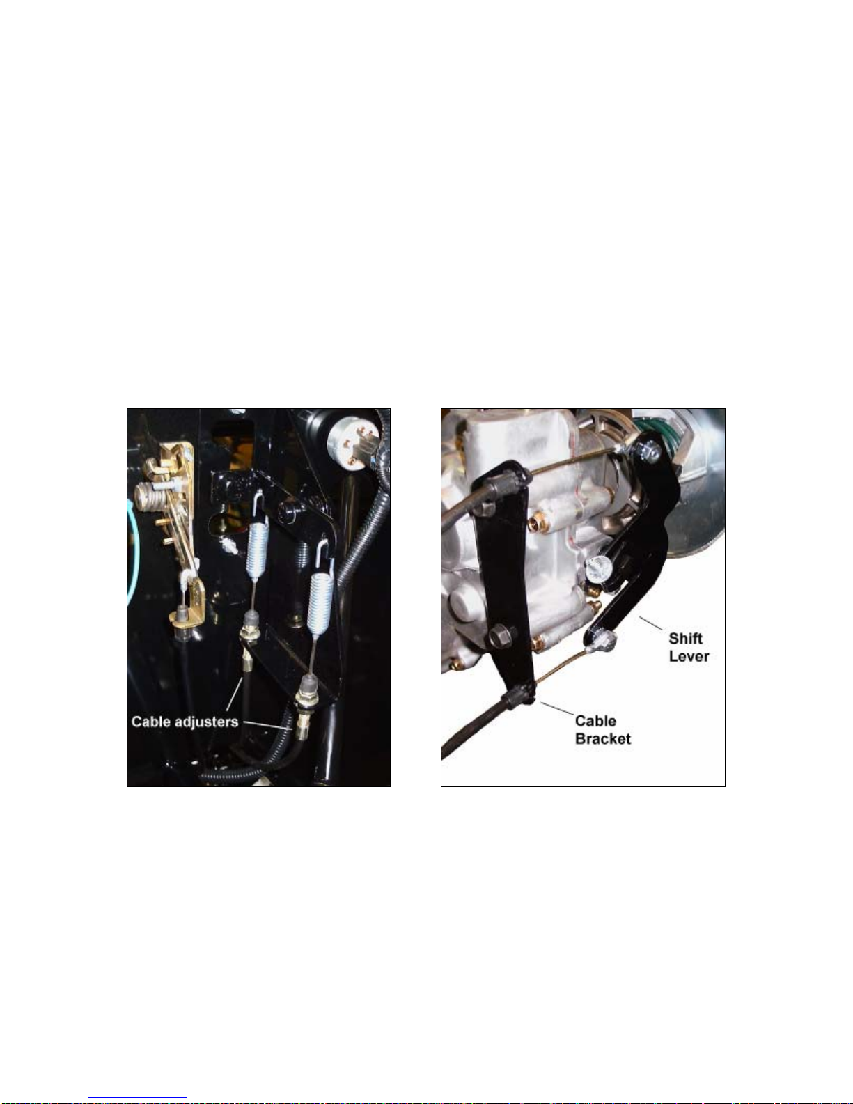
Vehicles with serial number greater than 17063.
(See brass tag near top of left rear shock absor eb r)
1. Put the vehicle in neutral.
2. Loosen the cable adjusters behind the dash board. (photo on left)
3. Make sure the selector lever on the dashboard is in neutral.
4. Make sure the transmission is in neutral. You can check by turning the key to Start. The
engine will only turn over if the transmission is in neutral.
5. Pull the slack out of both cables (but do not stretch the springs) and tighten the adjuster
nuts.
If you have tried all of this and it is still not operating correctly, you may need new cables. Please
call Brister’s Customer Service at 1-866-646-5278. Have your serial number handy when you call.
25
Page 26
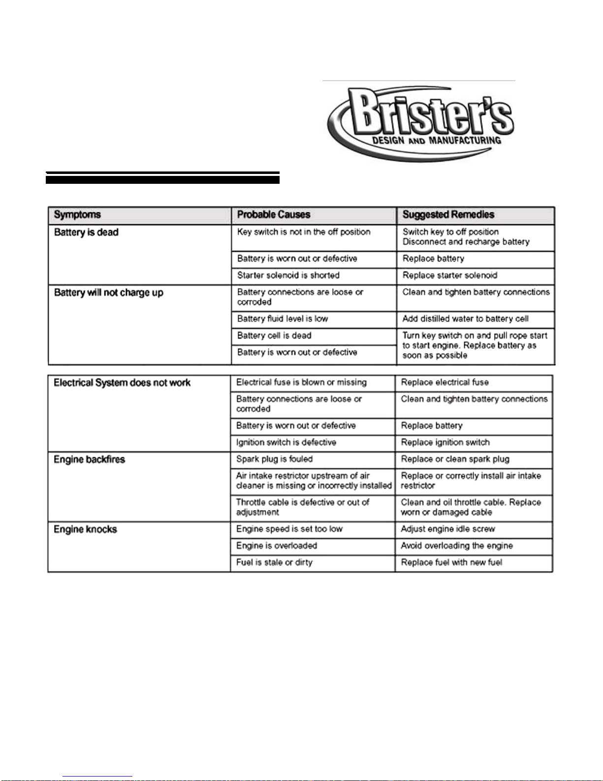
Section 6 Troubleshooting
26
Page 27

Tro b
u le Shooting
Steerin y/pulling to one side/hard to steer (Call normally for 4wd)
Eng
E
Engine will not start and does not turn over with electric starter.
Probable Cause
g feels funn
Pro b
ba le Cause:
•
One side may still be engaged in 4wd with the switch off.
Possible Remedy:
• Put unit in reverse and back up
• If this does not work take
ine Shuts down when turning or on inclines or uneven terrain-
Pro b
ba le Cause:
• Oil is low or Honda oil sensor is bad
Possible Remedy
• Check oil le
to not alert the low
• Honda Low oil alert sensor may be bad and
ngine will not start but does turn over with electric starter.
Probable Cause
• Fuel valve may be off, spark plug may be fouled (excessive idling or running unit with choke engaged can
cause plugs to foul), or engine oil may be low.
Possible Remedy
• Make sure fuel valve is on.
• Replace spark plug and try to restart.
• Check oil level with unit on level ground-Adding more oil or making sure the oil is completely full can help
to not alert the low oil sensor.
• Shifter is not in neutral, battery may be low or smission may be unplugged or
bad, key switch or its connections connectors m e unplugged or bad, electric starter may be bad.
Possible Solutions
Shifter must be in neutral
•
• Turn key to on position and use recoil start
• If this works recharge or replace the battery
• Check neutral switch on transmission to make s ged in.
• Check all connectio ns to key switch (switch may be unplugged behind fire wall).
• Key switch may be bad-switch must be changed out with new one
• Have authorized Honda Service Center check the electric starter
vel with unit on level ground-Adding more oil or making sure the oil is completely full can help
oil sensor.
straight
the unit to a service center.
a few feet to get the axle to release.
must be replaced by authorized Honda service center.
bad, neutral switch on tran
ay b
ure it is plug
27
Page 28

Gas in oil
Probable Cause
• Unit may have been transported with fuel valve on. Every time a unit is transported on a trailer or in a truck
the fuel must be shut off using the shut off valv e side of the engine. Leaving this valve open during
transport could allow fuel to be deposited into the crank case locking the engine up.
Possible Solution
• Oil in engine must be drained completely and ch nged with fresh oil
• Run unit and check oil again –if no gas is found in oil-unit is ready.
Brakes don’t work well / Hard to push / no travel in pedal
Probable Cause
• The brake rotors are dirty.
Possible Solution
4x4 units
• Clean the rotors with brake cleaner and test.
• A stiff pedal is normal for our 4x4 unit-
• A stiff pedal means good pressure in the brake lines
• Check brake pads and front calipers
2wd units
• The 2wd units have an automatic brake adjuste Put the unit in reverse, back up at low speed, and step
If you continue to have problems, discontinue use and take it directly to an authorized service center
Belt slipping/will not pull up hill
Probable Cause
• Too much weight (h
• The belt is wet
• The torque converter pulleys are dirty.
• Belt may have stretched or have a low spot causing slipping-replace belt
Possible Solution
• Lighten the load.
• Clean the torque converter and dry the belt
• Replace the belt
hard on the brakes. This should give enough br e adjustment.
auling/towing excessive weight can cause belt to slip).
e on th
a
r.
ak
28
Page 29
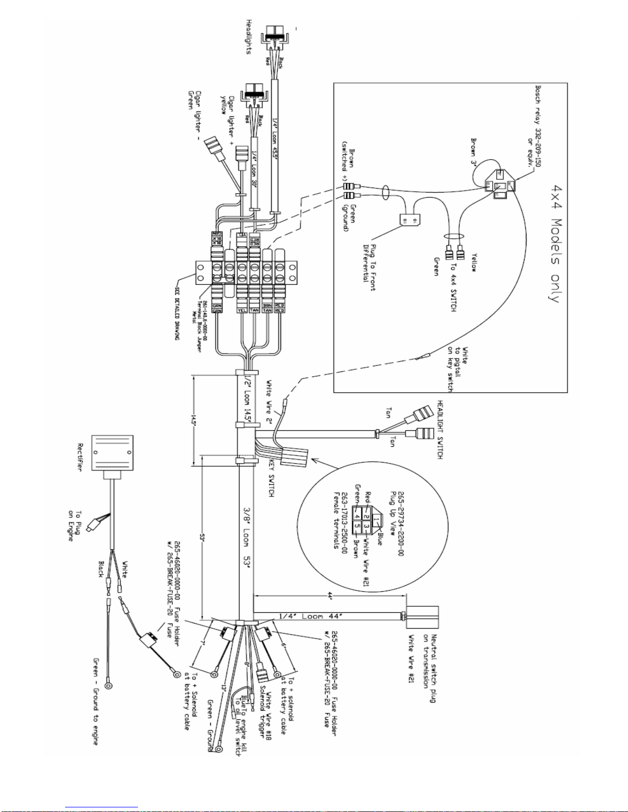
Wiring Diagram
All Mod
els
29
Page 30
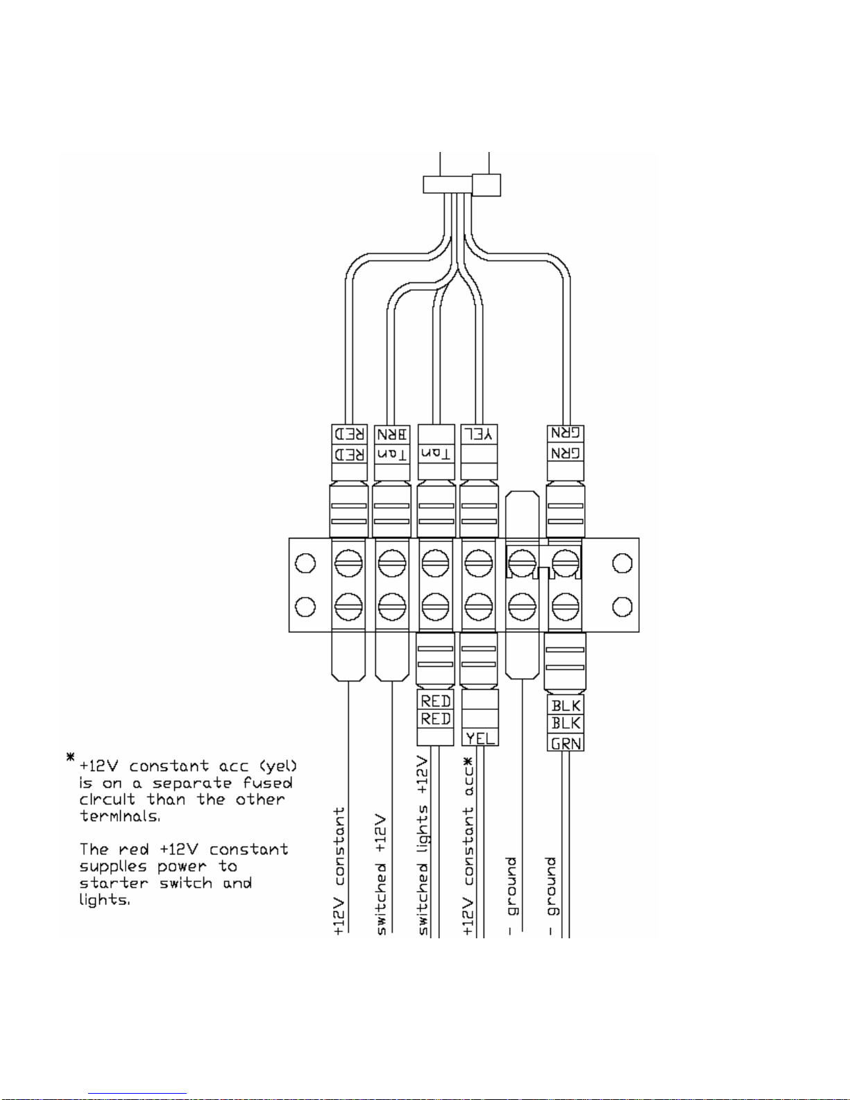
Terminal Block Wiring
30
Page 31

Section 7 Parts
Brister’s
2-wheel drive
Utility Vehicle
Parts
Breakdown
31
Page 32
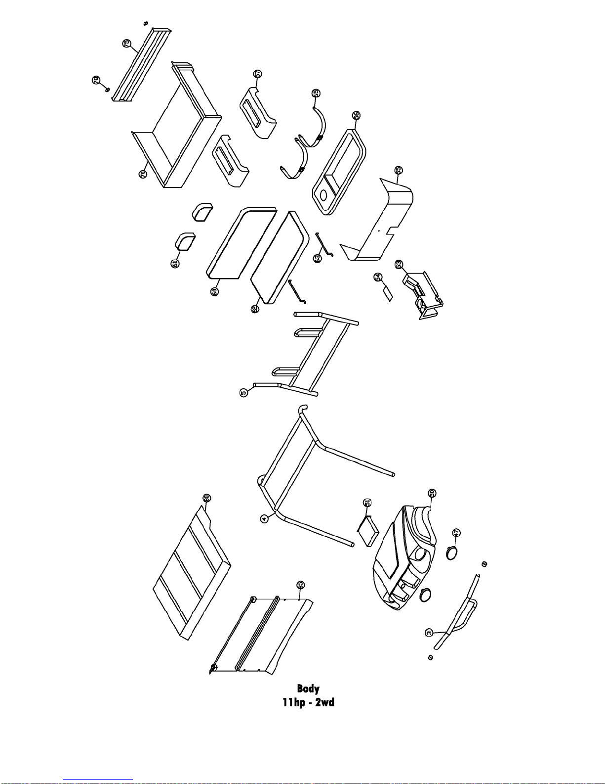
32
Page 33
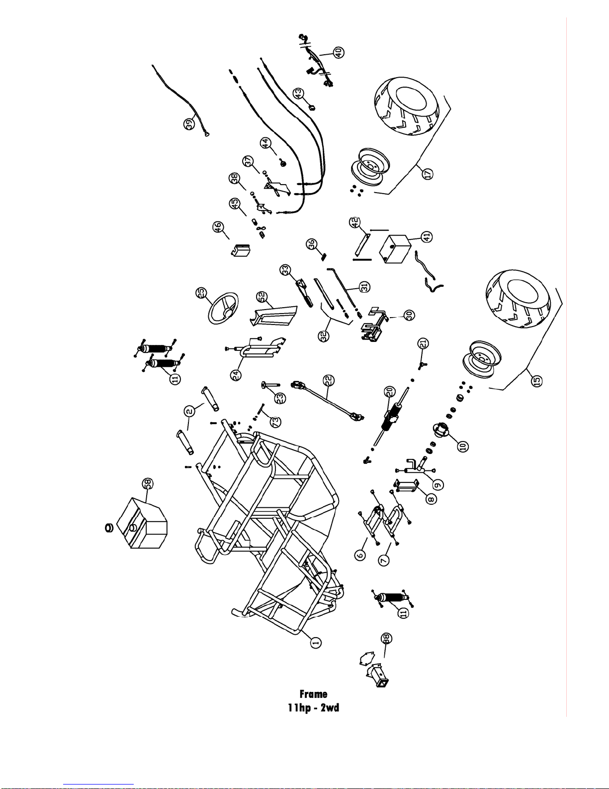
33
Page 34
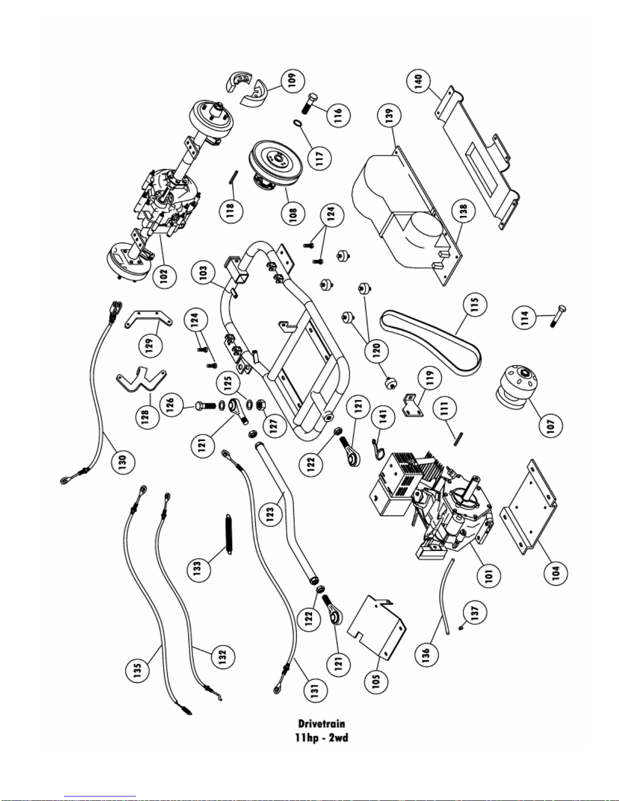
34
Page 35

Reference
Number
1 45419 Frame, CW11 1
2 45401 Rear frame stub, CW - black 2
50168 5/16 x 2-1/4" USS Socket Head bolt 2
50007 nut, 5/16 nylock 2
50702 bent washer 5/16 2
3 45413 bumper, CW - black 1
45432 Bumper, Trail Wagon – Black 1
50167 bolt, 5/16 x 2 4
50007 nut, 5/16 nylock 4
50702 bent washer 5/16 4
70208 Vinyl Caps 1 3/4 x 1 1/2 2
4 45412 Brush Guard roof, CW – black 1
50168 5/16 x 2-1/4” USS Socket Head bolt 4
50007 nut, 5/16 nylock 4
50702 bent washer 5/16 4
5 45411 brshgrd seat back, CW – black 1
50168 5/16 x 2-1/4” USS Socket Head bolt 2
50007 nut, 5/16 nylock 2
50702 bent washer 5/16 2
6 45404 A-arm upper, CW – black (left or right) 2
51100 suspension bu shings 4 ea
50262 bolt, 5/8 x 9” 1 ea
50254 Bolt, 5/8 x 3.5 bolt 1 ea
50015 Nut, 5/8 nylock 2 ea
7 45405 A-arm Lower, CW – black (left or right) 2
51100 suspension bu shings 4 ea
50262 bolt, 5/8 x 9” 1 ea
50254 Bolt, 5/8 x 3.5 bolt 1 ea
50015 Nut, 5/8 nylock 2 ea
8 45408 spindle mount, CW – black 2
9a 45406 Spindle, cw left – black 1
9b 45407 Spindle, cw right – black 1
51100 suspension bu shings 2 ea
50262 bolt, 5/8 x 9” 1 ea
50015 Nut, 5/8 nylock 1 ea
10 ete with Bearings & Seals 30604 Hub, 4 bolt high speed 1” Compl 2
11205 bearing, 1” tapered
30620 seal
30622 castle nut, 1”
30621 cotter pin
30623 ust cap d
Part
Number
Part Description - 2WD Models
Quantity
Required
35
Page 36

Reference
Number
50060 Lug nuts, ½”
11 70301 Shock, Heavy duty #1 6
50400 Bolt, 10 mm x 40mm 12
50065 Nut, 10mm nylock 12
15L 30122 Rim/Tire Assembly, UTV 22/9-10” Left 1
15R 2/9-10” Right 30123 Rim/Tire Assembly, UTV 2 1
30480 Wheel rim, 10” x 6”
30195 Tire, Pathfinder 22/9-10”
17L TV 22/11-10” Left 30124 Rim/Tire Assembly, U 1
17R 10” Right 30125 Rim/Tire Assembly, UTV 22/11- 1
30480 Wheel rim, 10” x 6”
30194 Tire, Pathfinder 22/11-10”
20 10521 Rack & pinion with rod ends 1
10593 Rack & Pinion Boots 2
10590 Rack & Pinion Rod 2
50171 Bolt, 5/16 x 3 ¾” USS 4
50005 Nut, 5/16 keps 4
50063 Nut, ½” SAE nylock 2
2 1 10524 Rod end 2
50078 Nut, ½” SAE jam 2
22 10522 Steering Shaft w/u-joints 1
50402 Bolt, 10mm x 30mm 1
50066 Nut, 10mm Tri Lock Jam 1
50403 Bolt, 8mm x 30mm 1
50780 Lock washer, 8mm 1
23 ck 45422 Steering Stub Shaft Assembly, CW – Bla 1
24 45400 Steering support, CW – black 1
51100 suspension bu shings 2 ea
50152 bolt, 5/16 x 1 4
50005 Nut, 5/16 keps 4
25 10502 Steering Wheel 13” 1
Center cap
screw, black center cap
50081 bolt, ¼ x 1 ¾ 3
50001 nut, ¼ nylock 3
30 ck 45402 Pedal assembly, CW – bla 1
50152 bolt, 5/16 x 1 6
50081 bolt, ¼ x 1 ¾” 1
50159 olt, 5/16 x 1 ½ b 1
50005 Nut, 5/16 keps 8
50701 asher, 5/16 flat W 2
Part
Number
Part Description – 2WD Models
Quantity
Required
36
Page 37

Reference
Number
31 11180 Brake Rod, with clevis 1
50215 bolt, 3/8 x 1 ¼ 1
50010 nut, 3/8” nylock 1
50801 cotter pin 1/8” x 1 1
32 r, CW – black 45417 parking brake ba 1
50806 Clevis, 5/16 rod end 1
50170 Bolt, 5/16”-24 X 4” SAE 1
50077 Nut, 5/16” Hex SAE 1
50087 olt, ¼” x 1 b 1
50001 nut, ¼” nylock 1
3 3 11127 Parking Brake 1
50086 Bolt, ¼ x 1 ¼ 1
50001 nut, ¼” nylock 1
50163 bolt, 5/16 x ¾” NC 4
50005 Nut, 5/16 keps 4
50701 Washer, 5/16 flat 4
36 45415 Brake equalizer, CW (2 ½”) – black 1
50215 bolt, 3/8 x 1 ¼ 2
50010 nut, 3/8” ny-lock 2
37 embly, black (built after 2-1-05) 11085 Shifter control ass 1
11083 Knob 1
11082 Cable, shifter (built after 2-1-05) 2
11080 Shifter Cable and Shifter Control (built before 2-1-05) 1
50053 nut, #10-24 Keps nut 2
50616 screw, #10-24 X ¾” Pan Head Phillips 2
50770 Washer, #10 flat 2
38 l assembly with cable and knob 11086 Differential Contro 1
11083 Knob
11090 Differential Control Handle – 1
11091 cable, diff lock
50053 nut, #10-24 Keps nut 2
50616 screw, #10-24 X ¾” Pan Head phillips 2
50770 Washer, #10 flat 2
4 0 70012 Wire Harness 1
41 -UTV 12Volt, 240 CCA 70000 Battery, U1L-8250 1
70002 Battery Cable, Red – 17” 1
70010 Battery Cable, Black (24”) 1
70009 Battery Terminal Cover 2
50087 bolt, ¼” x 1 2
50000 nut, ¼” keps 2
Part
Number
Part Description – 2WD Models
Quantity
Required
37
Page 38

Reference Part
Number umbe
42 45414 Battery strap, CW (8 ¾”) – black 1
50083 bolt, ¼ x 7 ½ 2
50002 nut, ¼” wing 2
4 3 70055 Light Switch 1
4 4 70052 Key Switch 1
70060 Key, 1 pair
4 5 70080 Accessory Plug 1
70081 Accessory Plug cap 1
46 tic 18500 Terminal Block Cover – plas 1
50625 screw, #10-24 X 1” Pan Head Phillips 2
50053 nut, #10-24 Keps nut 2
4 7 70129 Headlights 2
50 18311 Hood, plastic Green 1
18302 Hood, plastic Red
18350 Hood, plastic Camo
50620 ¼” X 1 ¼” Pan Head Phillips Machine screw 2
50621 ¼” X 2” Pan Head Phillips Machine screw 2
50717 ¼” SAE Flat washer 8
50001 nut, ¼” nylock 4
50846 Clamp-Tube-vinyl coated 1-1/4” 2
51 18309 Glove Box 1
50624 Screw, #10 x ¾ hex – black 5
52 18308 Steering Cover 1
18317 Steering Cover Bottom 1
50624 Screw, #10 x ¾ hex – black 1
53 18306 Center Console 1
50624 Screw, #10 x ¾ hex – black 14
54 18316 Access Cover, Center Console 1
50624 Screw, #10 x ¾ hex – black 4
55 18305 Plastic, Seat Bottom wrap 1
50624 Screw, #10 x ¾ hex – black 5
56 18304 Under seat storage box 1
57 18303 Rear Fender 1
50001 nut, ¼ nylock 4
50091 ¼”-20 X ¾” Carriage bolt 4
50717 ¼” SAE Flat washer 4
70150 Reflectors 2
N r
Part Description – 2WD Models
Quantity
Required
38
Page 39

Reference
Number
58 55060 Fuel Tank 1
55063 Elbow Fuel Inlet w/ #200 Mesh Screen 1
55062 Fuel Fitting Grommet 1
55061 Cap Fuel Tank 1
50163 bolt, 5/16 x 3/4" NC 3
50706 Washer, 5/16 fender 3
50703 Washer, 5/16 lock 3
60 10754 Seatback 43 ½ x 17 ½ 1
50619 #14 X 1-3/4” Pan head-Tapping screw 6
61 10803 Headrest – UTV 9 x 6 ½ 2
50085 bolt, ¼ x 1 ½” 4
62 10755 Seat bottom 43 ½ x 17 ½ 1
63 45416 seat bar, CW (17 ½”) – black 2
50609 #14 x ¾ Pan Head Screw 6
65 10705 Seat Belt, 2pt 2
50025 7/16 Nylock 4
70 45426 Cargo Bed, Green 1
45420 Cargo Bed, Red 1
45424 Cargo Bed, Black 1
18352 Camo Bed Panel Left 1
18353 Camo Bed Panel Right 1
18354 Camo Bed Panel Tail Gate 1
50255 5/8 x 4” bolt Zinc plate 2
50015 5/8 nylock 2
18402 Bed Rubber Plug 2
73 50208 Bed latch bolt, 3/8 x 2 1/2" 1
50013 nut, 3/8 keps 2
50740 washer, 3/8 flat 2
75 45427 Tail gate, green 1
45421 Tail gate, Red 1
45425 Tail gate, Black 1
50152 bolt, 5/16 x 1 2
50701 washer, 5/16 sae 4
50007 nut, 5/16 nylock 2
70230 rubber bump stops 4
78 50815 1/4" Lynch Pin - tailgate latch 2
Part
Number
Part Description – 2WD Models
Quantity
Required
39
Page 40

Reference
Number
80 18312 Roof, green 1
18301 Roof, Red 1
18351 Roof, Camo 1
18391 Roof, Top Vinyl Trim 1
18390 Roof, Hardware bolt kit
50847 Clamp-Tube-vinyl coated 1-3/4" 4
50087 bolt, 1/4" x 1 4
50718 Washer, ¼” rubber domed 4
50001 nut, 1/4" nylock 4
85 18400 Windshield - clear
18401 Windshield - tinted
18403 astener kit, windshield F
88 40723 Front receiver hitch kit
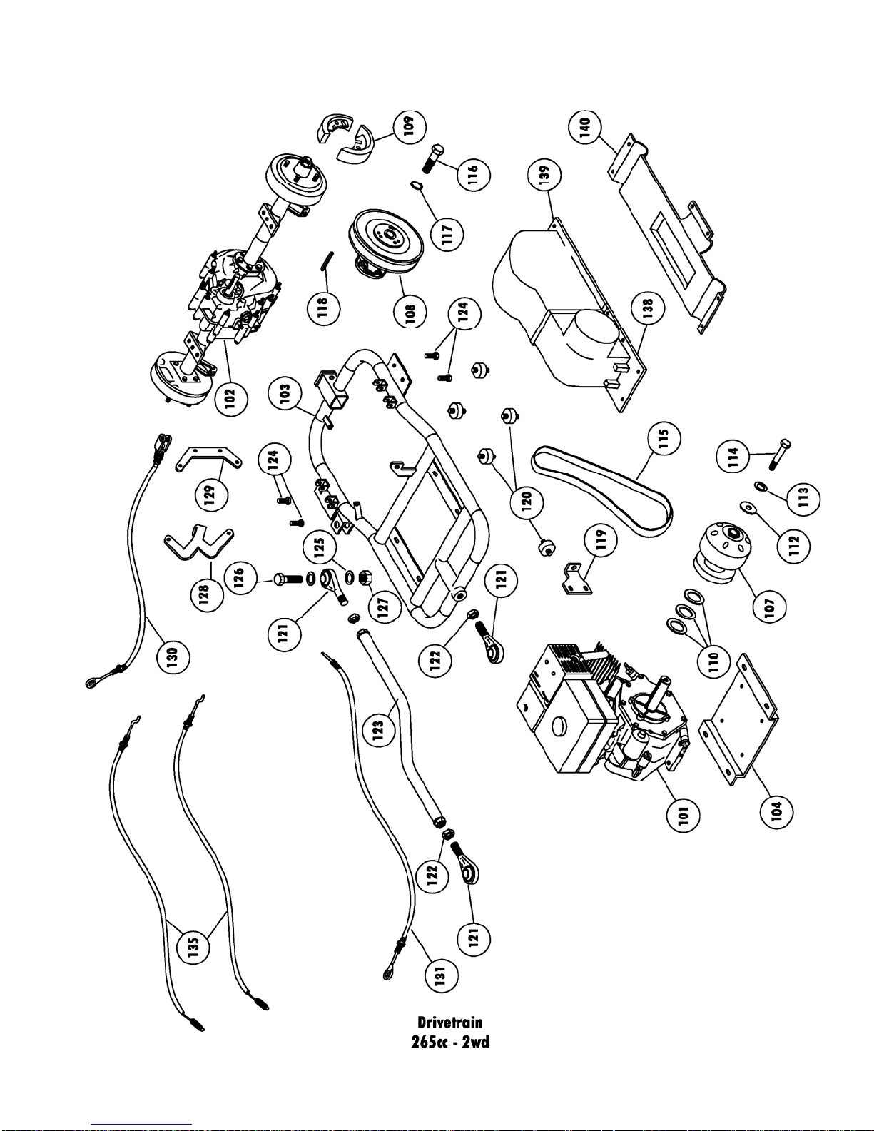
101 20010 Engine, Honda 11hp 1
- 50202 3/8-16 x 1 3/4" Hex Hd Bolt 4
- 50740 3/8" Flat washer, USS 4
102 20833 ana Transaxle D 1
70057 Neutral Safety Switch 1
51500 Shims – Neutral Safety Switch
103 45423 Swing arm, CW - Black 1
104 45430 Motor Plate, CW - Black 1
105 18023 Throttle Guard Laser 1
- 50086 1/4-20 x 1 1/4" Hex Hd Bolt 3
- 50082 1/4-20 x 2 1/4" Hex Hd Bolt 1
- 50000 /4" Keps Nut 1 5
- 50715 1/4" Flatwasher, USS 8
107 20648 TC, Driver Comet 500 – used before Serial Number # 25658 1
20665 TC, Driver CVTECH – used fter Serial Number # 25658 1 a
108 20649 TC, Driven Comet 500 – us efore Serial Number # 25658 1 ed b
20666 TC, Driven CVTECH – used fter Serial Number # 25658 1 a
109 11166 Brake Shoes - Rear UTV – Dana 2
110 50745 1" I.D. Spacer Washer – Comet only (not used with CVTech pulley) 4
111 - 1/4" Key stock 1
112 - 3/8" I.D. Fender Washer – Comet only (not used with CVTech pulley) 1
113 50741 3/8" Lock Washer – Comet only (not used with CVTech pulley) 1
114 50219 3/8x 3" Bolt Hex Hd NF – Comet only (not used with CVTech pulley) 1
115 20693 Belt, Comet 300668 - used before Serial Number # 25658 1
20694 Belt, CV TECH – used after Serial Number # 25658 1
116 50239 1/2 x 2" SAE 1
Part
Number
Part Description - 2WD Models
Quantity
Required
40
Page 41

Reference
Number
117 50722 1/2" Lock Washer 1
50721 1/2" Uss Flat Washer 1
118 - Key stock – Special Key – 3/16” X 1/4” X 31/2” 1
119 45431 Tension Mount Engine, CW - Black 1
- 50157 5/16x 3/4" Bolt Hex Hd NF 2
- 50703 5/16" Lock Washer 2
- 50704 5/16" Flatwasher 2
120 70250 Rubber Feet (Isolators) 5
- 50010 3/8 Nylock Nut 10
- 50740 3/8 Flatwasher USS 5
121 10581 Rod End Sphcl-UTV (4681-MPM-12) 3
122 50021 3/4 Jam n 3 ut SAE
123 45403 Panhard b 1 ar, CW - black
124 50206 bolt, 3/8 x 4 1
- 50010 3/8" Nyloc 4 k Nut
- 50740 3/8" Flatwas 4 her, USS
125 50730 3/4' Spacer W 6 asher
126 50280 3/4 x 2.5 SA 3 E bolt
127 500 3 20 3/4 SAE nylock
128 180 1 12 shifter lever, CW - black - used before Serial Number #15244
- 500 1 84 1/4-20 x 3/4" Hex Hd Bolt
- 2 50000 1/4" Keps Nut
129 1 18011 shifter cable mount, CW - black - used after Serial Number #15245
- 1 50084 1/4-20 x 3/4" Hex Hd Bolt
- 1 50000 1/4" Keps Nut
- 2 50715 1/4" Flatwasher, USS
130 11103 Brake Cables 2
- 50150 5/16-18 x 1" Hex Hd Bolt 2
- 50007 5/16" Nylock Nut 2
131 11010 Throttle Cable, UTV 1
- 50087 1/4-20 x 1" Hex Hd Bolt 1
- 50000 1/4" Keps Nut 2
- 11804 Spring #80704 Black painted 1
132 11084 Differential Cable All 2WD models before serial #22187 1
- 50087 1/4-20 x 1" Hex Hd Bolt 1
- 50000 1/4" Keps Nut 2
- 50159 5/16-18 x 1 1/2" Hex Hd Bolt 1
- 50005 5/16" Keps Nut 2
Part
Number
Part Description - 2WD Models
Quantity
Required
41
Page 42

Reference
Number
132 11086 Differential Control Assembly w/ cable all models after serial # 22187 1
- 11083 Knob 1
- 11091 Differential Control Cable Only used on all models after serial # 22187 1
- 50053 nut, #10-24 Keps nut 2
- 50616 screw, #10-24 X 3/4" Pan Head phillips 2
- 50770 Washer, #10 flat 2
- 50087 1/4-20 x 1" Hex Hd Bolt 1
- 50000 1/4" Keps Nut 2
- 50159 5/16-18 x 1 1/2" Hex Hd Bolt 1
- 50005 5/16" Keps Nut 2
133 11804 Spring #80704 Black painted 1
135 11080 Shifter Cable and Shifter Control - used before Serial Number #15244 1
11082 Cable, shifter - used after Serial Number #15245 2
136 65500 fuel hose 3/16" dia - 24" 1
137 50849 hose clamps - small 3
138 18313 Belt Guard Plastic UTV - Front 1
139 18314 Belt Guard Plastic UTV - Rear 1
140 18315 Belt Guard Plastic UTV - Bottom 1
- 50624 #10 x 3/4" Blunt Point Black 7
- 50050 #10 Speed Nut - for Plastic 7
- 50770 #10 Flat washer 7
141 20011 Choke Bracket Honda Engine 1
Part
Number
Part Description - 2WD Models
Quantity
Required
42
Page 43

Brister
265cc
Utility Vehicle
Parts Breakdown
43
Page 44
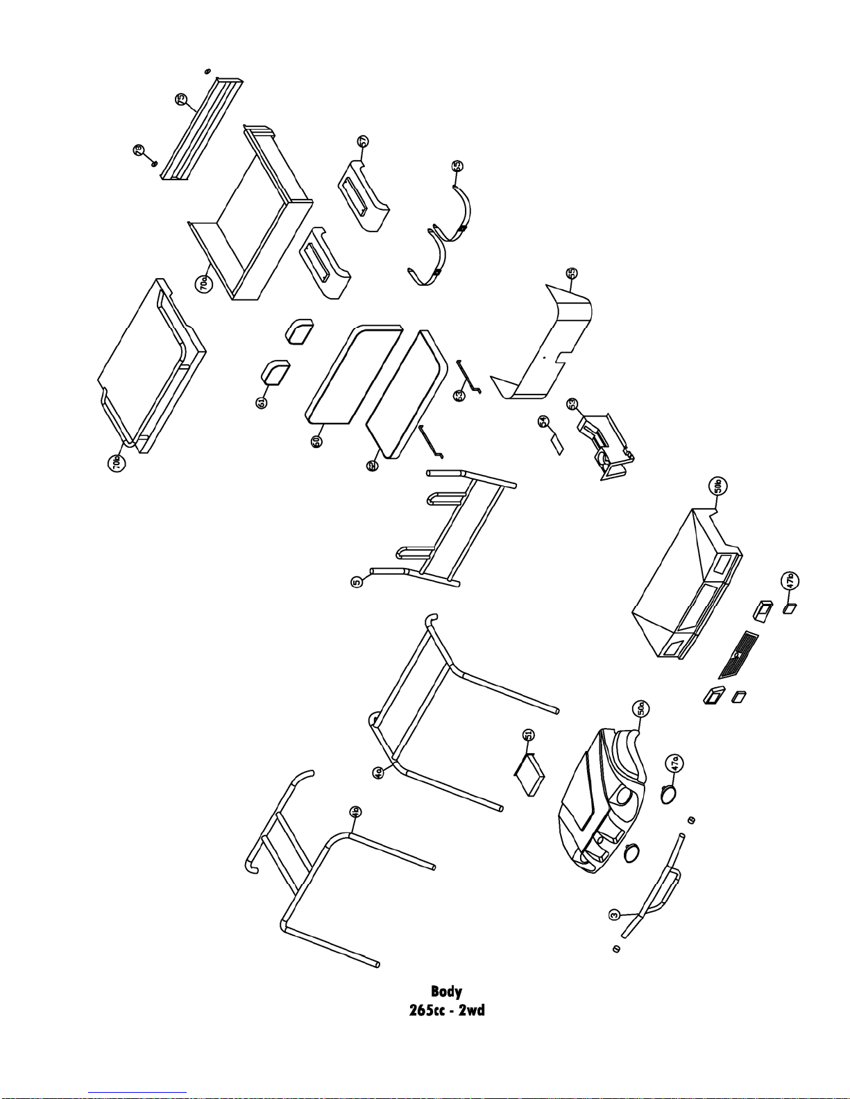
44
Page 45
45
Page 46
46
Page 47

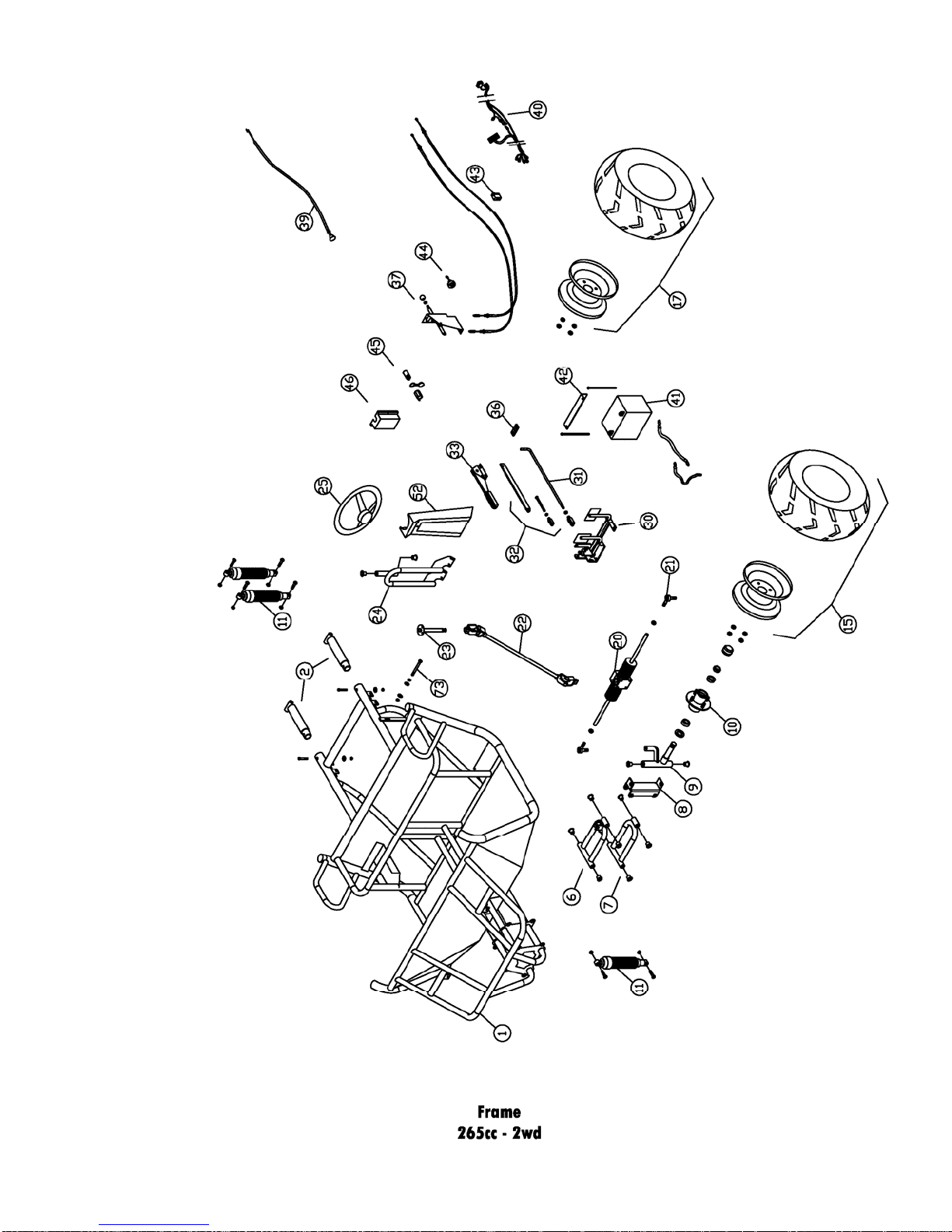
Reference
Num er N
1 45419 Frame, CW11 1
2 45401 Rear frame stub, CW - black 2
50168 5/16 x 2-1/4" USS Socket Head bolt 2
50007 nut, 5/16 nylock 2
50702 bent washer 5/16 2
3 45413 bumper, CW - black 1
45432 Bumper, Trail Wagon – Black 1
50167 bolt, 5/16 x 2 4
50007 nut, 5/16 nylock 4
50702 bent washer 5/16 4
70208 Vinyl Caps 1 3/4 x 1 1/2 2
4a f, CW265 – black 45412 Brush Guard roo 1
4b TW265 – black 42300 Brush Guard roof,
50168 5/16 x 2-1/4” USS Socket Head bolt 4
50007 nut, 5/16 nylock 4
50702 bent washer 5/16 4
5 45411 brshgrd seat back, CW – black 1
50168 5/16 x 2-1/4” USS Socket Head bolt 2
50007 nut, 5/16 nylock 2
50702 bent washer 5/16 2
6 42045 A-arm upper, 265 – black (left or right) 2
51100 suspension bushings 4 ea
50262 bolt, 5/8 x 9” 1 ea
50254 Bolt, 5/8 x 3.5 bolt 1 ea
50015 Nut, 5/8 nylock 2 ea
7 42046 A-arm Lower, 265 – black (left or right) 2
51100 suspension bushings 4 ea
50262 bolt, 5/8 x 9” 1 ea
50254 Bolt, 5/8 x 3.5 bolt 1 ea
50015 Nut, 5/8 nylock 2 ea
8 45408 pindle mount, CW – black s 2
9a 45406 Spindle, left – black 1
9b 45407 Spindle, right – black 1
51100 suspension bushings 2 ea
50262 bolt, 5/8 x 9” 1 ea
50015 Nut, 5/8 nylock 1 ea
10 30604 Hub, 4 bolt high speed 1” Complete with Bearings & Seals 2
11205 bearing, 1” tapered
30620 seal
Part
umber
Part Description – 265cc 2WD Models
Qu
Required b
antity
47
Page 48

Reference Part
Number umbe
30623 dust cap
30622 castle nut, 1”
30621 cotter pin
50060 Lug nuts, ½”
11 70301 Shock, Heavy duty #1 6
50400 Bolt, 10 mm x 40mm 12
50065 Nut, 10mm nylock 12
15L 30142 Rim/Tire Assembly, UTV 22/11-8” Front Left 1
15R TV 22/11-8” Front Right 30143 Rim/Tire Assembly, U 1
17L 30144 Rim/Tire Assembly, UTV 22/11-8” Rear Left 1
17R r Right 30145 Rim/Tire Assembly, UTV 22/11-8” Rea 1
20 ends 265 10596 Rack & pinion with rod 1
10593 Rack & Pinion Boots 2
Rack & Pinion Rod - 265 2
50171 Bolt, 5/16 x 3 ¾” USS 4
50005 Nut, 5/16 keps 4
50063 Nut, ½” SAE nylock 2
2 1 10524 Rod end 2
50078 Nut, ½” SAE jam 2
22 10522 Steering Shaft w/u-joints 1
50402 Bolt, 10mm x 30mm 1
50066 Nut, 10mm Tri Lock Jam 1
50403 Bolt, 8mm x 30mm 1
50780 Lock washer, 8mm 1
23 45422 Steering Stub Shaft Assembly, CW – Black 1
24 45400 Steering support, CW – black 1
51100 suspension bushings 2 ea
50152 bolt, 5/16 x 1 4
50005 Nut, 5/16 keps 4
25 10502 Steering Wheel 13” 1
Center cap
screw, black center cap
50081 bolt, ¼ x 1 ¾ 3
50001 nut, ¼ nylock 3
30 45402 Pedal assembly, CW – black 1
50152 bolt, 5/16 x 1 6
50081 bolt, ¼ x 1 ¾” 1
50159 bolt, 5/16 x 1 ½ 1
50005 Nut, 5/16 keps 8
50701 Washer, 5/16 flat 2
N r
Part Description – 265cc 2WD Models
Quantity
Required
48
Page 49

Reference
Number
31 11180 Brake Rod, with clevis 1
50215 bolt, 3/8 x 1 ¼ 1
50010 nut, 3/8” nylock 1
50801 cotter pin 1/8” x 1 1
32 45417 parking brake bar, CW – black 1
50806 Clevis, 5/16 rod end 1
50170 Bolt, 5/16”-24 X 4” SAE 1
50077 Nut, 5/16” Hex SAE 1
50087 bolt, ¼” x 1 1
50001 nut, ¼” nylock 1
33 11127 Parking Brake 1
50086 Bolt, ¼ x 1 ¼ 1
50001 nut, ¼” nylock 1
50163 bolt, 5/16 x ¾” NC 4
50005 Nut, 5/16 keps 4
50701 Washer, 5/16 flat 4
36 CW (2 ½”) – black 45415 Brake equalizer, 1
50215 bolt, 3/8 x 1 ¼ 2
50010 nut, 3/8” ny-lock 2
37 mbly, black (built after 2-1-05) 11085 Shifter control asse 1
11083 Knob 1
11082 Cable, shifter (built after 2-1-05) 2
11080 Shifter Cable and Shifter Control (built before 2-1-05) 1
50053 ut, #10-24 Keps nut n 2
50616 crew, #10-24 X ¾” Pan Head Phillips s 2
50770 Washer, #10 flat 2
40 70053 Wire Harness – 265 1
41 70000 Battery, U1L-8250-UTV 12Volt, 240 CCA 1
70002 Battery Cable, Red – 17” 1
70010 Battery Cable, Black (24”) 1
70009 Battery Terminal Cover 2
50087 bolt, ¼” x 1 2
50000 nut, ¼” keps 2
Part
Number
Part Description – 265cc 2WD Models
Quantity
Required
49
Page 50

Reference
Number
42 45414 Battery strap, CW (8 ¾”) – black 1
50083 bolt, ¼ x 7 ½ 2
50002 nut, ¼” wing 2
43 70055 Light Switch 1
4 4 70052 Key Switch 1
70060 Key, 1 pair
45 70080 Accessory Plug 1
70081 Accessory Plug cap 1
46 18500 Terminal Block Cover – plastic 1
50625 screw, #10-24 X 1” Pan Head Phillips 2
50053 nut, #10-24 Keps nut 2
47a 70129 Headlights CW265 – oval 2
47b 70133 Headlights TW265 – rectangular 2
50a 18302 Hood, plastic Red CW265 1
50b 18350 Hood, plastic Yellow TW265 1
18387 TW265 grill 1
18389 TW265 headlight bucket - left 1
18388 TW265 headlight bucket - right 1
50620 ¼” X 1 ¼” Pan Head Phillips Machine screw 2
50621 ¼” X 2” Pan Head Phillips Machine screw 2
50717 ¼” SAE Flat washer 8
50001 nut, ¼” nylock 4
50846 Clamp-Tube-vinyl coated 1-1/4” 2
51 18309 Glove Box 1
50624 Screw, #10 x ¾ hex – black 5
52 18308 Steering Cover 1
18317 Steering Cover Bottom 1
50624 Screw, #10 x ¾ hex – black 1
53 18306 Center Console 1
50624 Screw, #10 x ¾ hex – black 14
54 18316 Access Cover, Center Console 1
50624 Screw, #10 x ¾ hex – black 4
55 18305 Plastic, Seat Bottom wrap 1
50624 Screw, #10 x ¾ hex – black 5
57 18303 Rear Fender CW only 1
50001 nut, ¼ nylock 4
50091 ¼”-20 X ¾” Carriage bolt 4
50717 ¼” SAE Flat washer 4
70150 eflectors R 2
Part
Number
Part Description – 265cc 2WD Models
Quantity
Required
50
Page 51

Reference
Number
60 10754 Seatback 43 ½ x 17 ½ 1
50619 #14 X 1-3/4” Pan head-Tapping screw 6
61 10803 Headrest – UTV 9 x 6 ½ 2
50085 bolt, ¼ x 1 ½” 4
62 10755 Seat bottom 43 ½ x 17 ½ 1
63 45416 seat bar, CW (17 ½”) – black 2
50609 #14 x ¾ Pan Head Screw 6
65 10705 Seat Belt, 2pt 2
50025 7/16 Nylock 4
70a 45420 Cargo Bed, Red CW265 1
70b 45434 Flat Cargo Bed, Black - TW265 1
50255 5/8 x 4” bolt Zinc plate 2
50015 5/8 nylock 2
18402 Bed Rubber Plug 2
73 50208 Bed latch bolt, 3/8 x 2 1/2" 1
50013 ut, 3/8 keps n 2
50740 asher, 3/8 flat w 2
75 45421 Tail gate, Red 1
50152 bolt, 5/16 x 1 2
50701 washer, 5/16 sae 4
50007 nut, 5/16 nylock 2
70230 rubber bump stops 4
78 50815 1/4" Lynch Pin - tailgate latch 2
Part
Number
Part Description – 265cc 2WD Models
Quantity
Required
51
Page 52

Reference
Number
101 20016 Engine, Subaru 265cc 1
- 50202 3/8-16 x 1 3/4" Hex Hd Bolt 4
- 50740 3/8" Flat washer, USS 4
102 20869 Dana Transaxle – 265 mode 1 ls
70057 Neutral Safety Switch 1
51500 Shims – Neutral Safety Swi tch
103 45423 Swing arm, CW - Black 1
104 45430 Motor Plate, CW - Black 1
107 20667 TC, Driver Comet 40 1
108 20668 TC, Driven Comet 40 1
109 11166 Brake Shoes - Rear UTV – Dana 2
110 50745 1" I.D. Spacer Washer 4
112 50795 7/16" I.D. Fender Washer 1
113 50793 7/16” Lock Washer 1
114 50302 7/16 x 2 ½ SAE Bolt 1
115 20693 Belt, Com 1 et 300668
116 50239 1/2 x 2" SA 1 E
Part
Number
Part Descri n - 265cc 2WD Models
ptio
Quantity
Required
117 50722 1/2" Lock 1 Washer
50721 1/2" Uss F 1 lat Washer
118 1019 1 1 Key stock – 3/16”
119 1806 1 1 Tension Mount Engine, 265 - Black
- 5015 2 7 5/16x 3/4" Bolt Hex Hd NF
- 507 2 03 5/16" Lock Washer
- 507 2 04 5/16" Flatwasher
120 702 5 50 Rubber Feet (Isolators)
- 500 10 10 3/8 Nylock Nut
- 5 50740 3/8 Flatwasher USS
121 3 10581 Rod End Sphcl-UTV (4681-MPM-12)
122 3 50021 3/4 Jam nut SAE
123 1 45403 Panhard bar, CW - black
124 50206 bolt, 3/8 x 1 4
- 50010 3/8" Nylock Nut 4
- 50740 3/8" Flatwasher, USS 4
125 50730 3/4' Spacer Washer 6
126 50280 3/4 x 2.5 SAE bolt 3
127 50020 3/4 SAE nylock 3
128 18011 Shifter cable mount
52
Page 53

Reference
Number
129 18012 shifter cable lever, 1
- 50084 1/4-20 x 3/4" Hex Hd Bolt 1
- 50000 1/4" Keps Nut 1
- 50715 1/4" Flatwasher, USS 2
130 11103 Brake Cables 2
- 50150 5/16-18 x 1" Hex Hd Bolt 2
- 50007 5/16" Nylock Nut 2
131 11013 Throttle Cable, 265 1
135 11082 Cable, shifter 2
138 18313 Belt Guard Plastic UTV - Fr 1 ont
139 18314 Belt Guard Plastic UTV - Re 1 ar
140 18315 Belt Guard Plastic UTV - Bottom 1
- 50624 #10 x 3/4" Blunt Point Black 7
- 50050 #10 Speed Nut - for Plastic 7
- 50770 #10 Flat washer 7
Part
Number
Part Descri - 265cc 2WD Models
ption
Quantity
Required
53
Page 54

Brister
4-wheel drive
Utility Vehicle
Parts Breakdown
54
Page 55
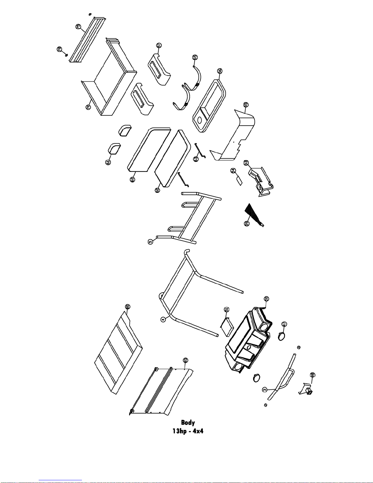
55
Page 56
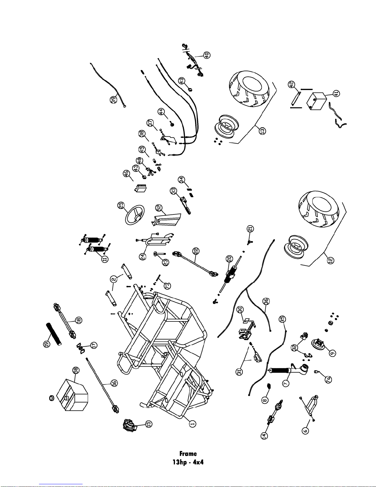
56
Page 57
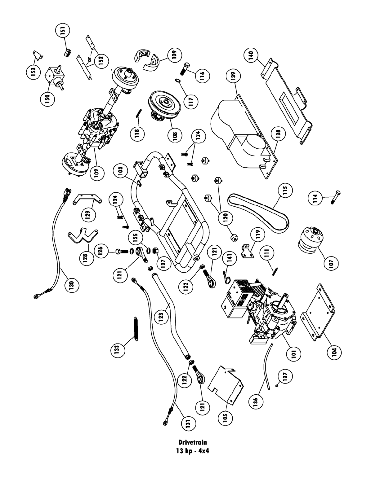
57
Page 58

Referenc
Num Nu
/16 50702 bent washer 5 2
e
Part
ber
1 45501 Frame, CW413 - 4x4 1
2 45401 Rear frame stub, CW - black 2
50168 5/16 x 2-1/4" USS Socket Head bolt 2
50007 nut, 5/16 nylock 2
3 45413 Bumper, CW - black 1
45433 Bumper, Trail Wagon – with grill guard - Black
50167 bolt, 5/16 x 2 4
50007 nut, 5/16 nylock 4
50702 bent washer 5/16 4
70208 Vinyl Caps 1 3/4 x 1 1/2 2
4 45412 Brush guard roof, CW - black 1
50168 5/16 x 2-1/4" USS Socket Head bolt 4
50007 nut, 5/16 nylock 4
50702 bent washer 5/16 4
5 45411 Brush guard seat back, CW - black 1
50168 5/16 x 2-1/4" USS Socket Head bolt 2
50007 nut, 5/16 nylock 2
50702 bent washer 5/16 2
6 43007 A-arm 4x4, CW – black (left or right) 2
51100 suspension bushings 2 ea
50266 bolt, 5/8 x 9 1/2" 1 ea
50015 Nut, 5/8 nylock 1 ea
45150 Spacer/CW A-arm bushing-4x4
7 25001 Strut assembly, left 1
25009 Strut assembly, right 1
50028 Nut, 7/16 NF jam 2
50041 Nut, 3/8 NF slotted 2
50801 cotter pin 1/8" x 1 2
7a 25020 Lower ball joint 2
8 25003 strut bearing 2
50163 bolt, 5/16 x 3/4" NC 8
50005 Nut, 5/16 keps 8
9 25002 Hub / rotor 4x4 2
50040 Nut, 5/8 NF slotted 2
30621 cotter pin 2
30623 dust cap 2
50060 Lug nuts, 1/2" 16
11 70301 Shock, Heavy duty #1 4
50400 Bolt, 10 mm x 40mm 6
50404 10 mm x 70mm bolt 2
50065 Nut, 10mm nylock 8
spacer, shock 2
12L bly, UTV 22/9-10" Left 30122 Rim/Tire Assem 1
12R 30123 im/Tire Assembly, UTV 22/9-10" Right R 1
30480 Wheel rim, 10" x 6"
30195 Tire, Pathfinder 22/9-10"
mber
Part Description – 4x4mo
dels
Quantity
Requir
ed
58
Page 59

Reference Part
Number Numb
13L 30124 Rim/Tire Assembly, UTV 22/11-10" Left 1
13R " Right 30125 Rim/Tire Assembly, UTV 22/11-10 1
30480 Wheel rim, 10" x 6"
30194 Tire, Pathfinder 22/11-10"
14 20851 CV half shaft (axle) – (Left or Right) 2
20868 Boot CV
15 tial – 4x4 20839 front differen 1
20848 Hilliard Front Differential Replacement Oil
50206 Bolt, 3/8 x 1 4
50740 washer, 3/8 flat 4
50741 washer, 3/8 lock 4
16 25006 drive shaft, front 1
50092 bolt, ¼ x 2” 2
50003 nut, ¼ keps 2
17 25008 bearing, shaft support 1
50163 bolt, 5/16 x ¾” NC 2
50005 Nut, 5/16 keps 2
18 25007 drive shaft, rear telescoping 1
50631 Screw, 3/8” – 16 x ½” square head set 2
10184 key, 3/16 x 1 3
19 g 17 inch 20804 convoluted tubin
20 10591 Rack & pinion with rod ends 4x4 1
10593 Rack & Pinion Boots 2
50171 Bolt, 5/16 x 3 3/4" USS 4
50005 Nut, 5/16 keps 4
21 10594 Rod end 4x4 2
10595 Tie rod 4x4 2
10593 Rack boot 2
22 10592 Steering Shaft w/u-joints 4x4 1
50402 Bolt, 10mm x 30mm 1
50066 Nut, 10mm Tri Lock Jam 1
50403 Bolt, 8mm x 30mm 1
50780 Lock washer, 8mm 1
23 45422 Steering Stub Shaft Assembly, CW - Black 1
24 pport, CW - black 45400 Steering su 1
51100 suspension bushings 2 ea
50152 bolt, 5/16 x 1 4
50005 Nut, 5/16 keps 4
2 5 10502 Steering Wheel 13" 1
10506 Center cap
screw, black center cap
50081 bolt, 1/4 x 1 3/4 3
50001 nut, 1/4 nylock 3
30 - black 45402 Pedal assembly, CW 1
50152 olt, 5/16 x 1 b 6
50081 olt, 1/4 x 1 3/4" b 1
50159 bolt, 5/16 x 1 1/2 1
50005 Nut, 5/16 keps 8
50701 Washer, 5/16 flat 2
er
Part Description – 4x4models
Quantity
Required
59
Page 60

Reference
Number
31 11123 master cylinder 1
50167 bolt, 5/16 x 2 2
50005 Nut, 5/16 keps 2
50806 Clevis, 5/16 rod end 1
50077 Nut, 5/16" Hex SAE 1
32 11124 brake caliper 2
11167 brake pads (2 pads required per wheel) 4
11168 brake pins 4
11169 brake clips 4
50826 Spacer Lock collar, 3/8 4
50217 bolt, 3/8 x 1 1/2 4
50013 nut, 3/8 keps 4
18030 caliper bracket 2
3 3 11127 Parking Brake 1
50086 Bolt, 1/4 x 1 1/4 1
50001 nut, 1/4" nylock 1
50163 bolt, 5/16 x 3/4" NC 4
50005 Nut, 5/16 keps 4
50701 Washer, 5/16 flat 4
3 r 4 18038 Brake spreade 2
50152 bolt, 5/16 x 1 4
50007 nut, 5/16 nylock 1
35 nt 11135 Brake hose, fro 1
36 11136 Brake hose, rear 1
37 11085 Shifter control assembly, black 1
11083 Knob 1
11082 Cable, shifter 2
50053 nut, #10-24 Keps nut 2
50616 screw, #10-24 X 3/4" Pan Head phillips 2
50770 Washer, #10 flat 2
3 Control Assy - 4x4 Diff Control w/ cable 8 11086 Differential 1
11083 Knob 1
11091 cable, diff lock 1
50053 nut, #10-24 Keps nut 2
50616 screw, #10-24 X 3/4" Pan Head phillips 2
50770 Washer, #10 flat 2
50087 1/4-20 x 1" Hex Hd Bolt 1
50000 1/4" Keps Nut 2
50159 5/16-18 x 1 1/2" Hex Hd Bolt 1
50005 5/16" Keps Nut 2
4 0 70012 Wire Harness 1
41 12 Volt – 240 CCA 70000 Battery, U1L-8250-UTV – 1
70002 Battery Cable, Red - 17" 1
70010 Battery Cable, Black (24") 1
70009 Battery Terminal Cover 2
50087 bolt, 1/4" x 1 2
50000 nut, 1/4" keps 2
50000 nut, 1/4" keps 2
Part
Number
Part Description – 4x4models
Quantity
Required
60
Page 61

Reference
Number
42 45414 Battery strap, CW (8 3/4") - black 1
50083 bolt, 1/4 x 7 1/2 2
50002 nut, 1/4" wing 2
43 70055 Light Switch / 4x4 switch 2
4 4 70052 Key Switch 1
70060 Key, 1 pair
4 5 70080 Accessory Plug 1
70081 Accessory Plug cap 1
46 18500 Terminal Block Cover - plastic 1
50625 screw, #10-24 X 1" Pan Head phillips 2
50053 nut, #10-24 Keps nut 2
47 70129 Headlights 2
48 70019 Relay w/harness, 4x4 1
50 18380 ) Hood, plastic - 4x4 (green 1
18384 Hood, plastic - 4x4 (camo) 1
18381 Hood, plastic - 4x4 (red) 1
50620 1/4" X 1 1/4" Pan phillips Machine screw 2
50621 1/4" X 2" Pan phillips Machine screw 2
50717 1/4" SAE Flat washer 8
50001 nut, 1/4" nylock 4
50846 Clamp-Tube-vinyl coated 1-1/4" 2
5 1 18309 Glove Box 1
50624 hex - black Screw, #10 x 3/4 5
52 18308 Steering Cover 1
50624 Screw, #10 x 3/4 hex - black 1
53 18383 Center Console 4x4 1
50624 Screw, #10 x 3/4 hex - black 14
54 18316 Access Cover, Center Console 1
50624 Screw, #10 x 3/4 hex - black 4
55 rap 4x4 18382 Plastic, Seat Bottom w 1
50624 Screw, #10 x 3/4 hex - black 5
56 18304 Underseat storage box 1
57 18303 Rear Fender 1
70150 Reflectors 2
50091 1/4"-20 X 3/4" Carriage bolt 4
50717 1/4" SAE Flat washer 4
58 55060 Fuel Tank 1
55063 Elbow Fuel Inlet w/ #200 Mesh Screen 1
55062 Fuel Fitting Grommet 1
55061 Cap Fuel Tank 1
50163 bolt, 5/16 x 3/4" NC 3
50706 Washer, 5/16 fender 3
50703 Washer, 5/16 lock 3
5 9 18033 Shaft guard 1
50163 bolt, 5/16 x 3/4" NC 3
50005 Nut, 5/16 keps 4
50171 Bolt, 5/16 x 3 3/4" USS 1
10001 tube, 1" 14ga 1
Part
Number
Part Description – 4x4models
Quantity
Required
61
Page 62

Reference
Number
60 10754 Seatback 43 1/2 x 17 1/2 1
50619 #14 X 1-3/4" Pan head-Tapping screw 6
61 10803 Headrest - UTV 9 x 6 1/2 2
50085 bolt, 1/4 x 1 1/2" 4
62 10755 Seat bottom 43 1/2 x 17 1/2 1
63 45416 seat bar, CW (17 1/2") - black 2
50609 #14 x 3/4 pan head tapping 6
65 10705 Seat Belt, 2pt 2
50025 7/16 Nylock 4
70 45426 Cargo Bed, Green 1
45420 Cargo Bed, Red 1
45424 Cargo Bed, Black 1
18352 Camo Bed Panel Left 1
18353 Camo Bed Panel Right 1
18354 Camo Bed Panel Tail Gate 1
50255 5/8 x 4” bolt Zinc plate 2
50015 5/8 nylock 2
18402 Bed Rubber Plug 2
73 50208 Bed latch bolt, 3/8 x 2 1/2" 1
50013 nut, 3/8 keps 2
50740 washer, 3/8 flat 2
75 45427 Tail gate, green 1
45421 Tail gate, Red 1
45425 Tail gate, Black 1
50152 bolt, 5/16 x 1 2
50701 washer, 5/16 sae 4
50007 nut, 5/16 nylock 2
70230 rubber bump stops 4
78 50815 1/4" Lynch Pin - tailgate latch 2
80 18312 Roof, green 1
18301 Roof, Red 1
18351 Roof, Camo 1
18391 Roof, Top Vinyl Trim 1
18390 Roof, Hardware bolt kit
50847 Clamp-Tube-vinyl coated 1-3/4" 4
50087 bolt, 1/4" x 1 4
50717 1/4" SAE Flat washer 4
50001 nut, 1/4" nylock 4
50718 Washer, ¼” Rubber Domed 4
85 18400 Windshield - clear
18401 Windshield - tinted
18403 Fastener kit, windshield
88 40729 Front receiver hitch 4x4 kit 1
50162 Bolt, 5/16 x 1-3/8 - U 4
50704 Washer, 5/16 Flat 8
50007 Nut, 5/16 Nylock 8
101 20012 Engine, Honda 13hp 1
50202 3/8-16 x 1 3/4" Hex Hd Bolt 4
50740 3/8" Flatwasher, USS 4
102 20838 Dana Transaxle 4x4 1
Part
Number
Part Description – 4x4models
Quantity
Required
62
Page 63

Reference
Number
103 45502 Swing arm, CW - Black 4x4 1
104 45430 Motor Plate, CW - Black 1
105 18023 Throttle Guard Laser 1
50086 1/4-20 x 1 1/4" Hex Hd Bolt 3
50082 1/4-20 x 2 1/4" Hex Hd Bolt 1
50000 1/4" Keps Nut 5
50715 1/4" Flatwasher, USS 8
107 20648 TC, Driver Comet 500 – used before Serial Number #25663 1
20665 TC, Driver CVTECH – used after Serial Number #25663 1
108 20649 TC, Driven Comet 500 – used before Serial Number #25663 1
20666 TC, Driven CVTECH – used after Serial Number #25663 1
109 11166 Brake Shoes - Rear UTV – Dana ( 1 set per wheel) 2
110 50745 1" I.D. Spacer Washer– Comet only (not used with CVTech pulley) 4
111 - 1/4 x 3/16" Keystock 1
112 50742 3/8" I.D. Fender Washer– Comet only (not used with CVTech pulley) 1
113 50741 3/8" Lock Washer– Comet only (not used with CVTech pulley) 1
114 50219 3/8x 3" Bolt Hex Hd NF– Comet only (not used with CVTech pulley) 1
115 20693 Belt, Comet 300668 used before Serial Number # 25663 1
20694 Belt, CV TECH – used after Serial Number # 25663 1
116 50239 1/2 x 2" SAE 1
117 50722 1/2" Lock Washer 1
50721 1/2" Uss Flat Washer 1
118 - 3/16" Key stock 1
119 45431 Tension Mount Engine, CW - Black 1
50157 5/16x 3/4" Bolt Hex Hd NF 2
50703 5/16" Lock Washer 2
50704 5/16" Flatwasher 2
120 70250 Rubber Feet (Isolators) 5
50010 3/8 Nylock Nut 10
50740 3/8 Flatwasher USS 5
121 10581 Rod End Sphcl-UTV (4681-MPM-12) 3
122 50021 3/4 Jam nut SAE 3
123 42093 Panhard bar, CW - black 4x4 1
124 50206 bolt, 3/8 x 1 4
50010 3/8" Nylock Nut 4
50740 3/8" Flatwasher, USS 4
125 50730 3/4' Spacer Washer 6
126 50280 3/4 x 2.5 SAE bolt 3
127 50020 3/4 SAE nylock 3
128 18012 shifter lever, CW - black 1
50084 1/4-20 x 3/4" Hex Hd Bolt 2
50000 1/4" Keps Nut 4
129 18011 shifter cable mount, CW - black 1
130 11104 Parking Brake Cables 4x4 2
50150 5/16-18 x 1" Hex Hd Bolt 2
50007 5/16" Nylock Nut 2
131 11010 Throttle Cable, UTV 1
50087 1/4-20 x 1" Hex Hd Bolt 1
50000 1/4" Keps Nut 2
11804 Spring #80704 Black painted 1
Part
Number
Part Description – 4x4models
Quantity
Required
63
Page 64
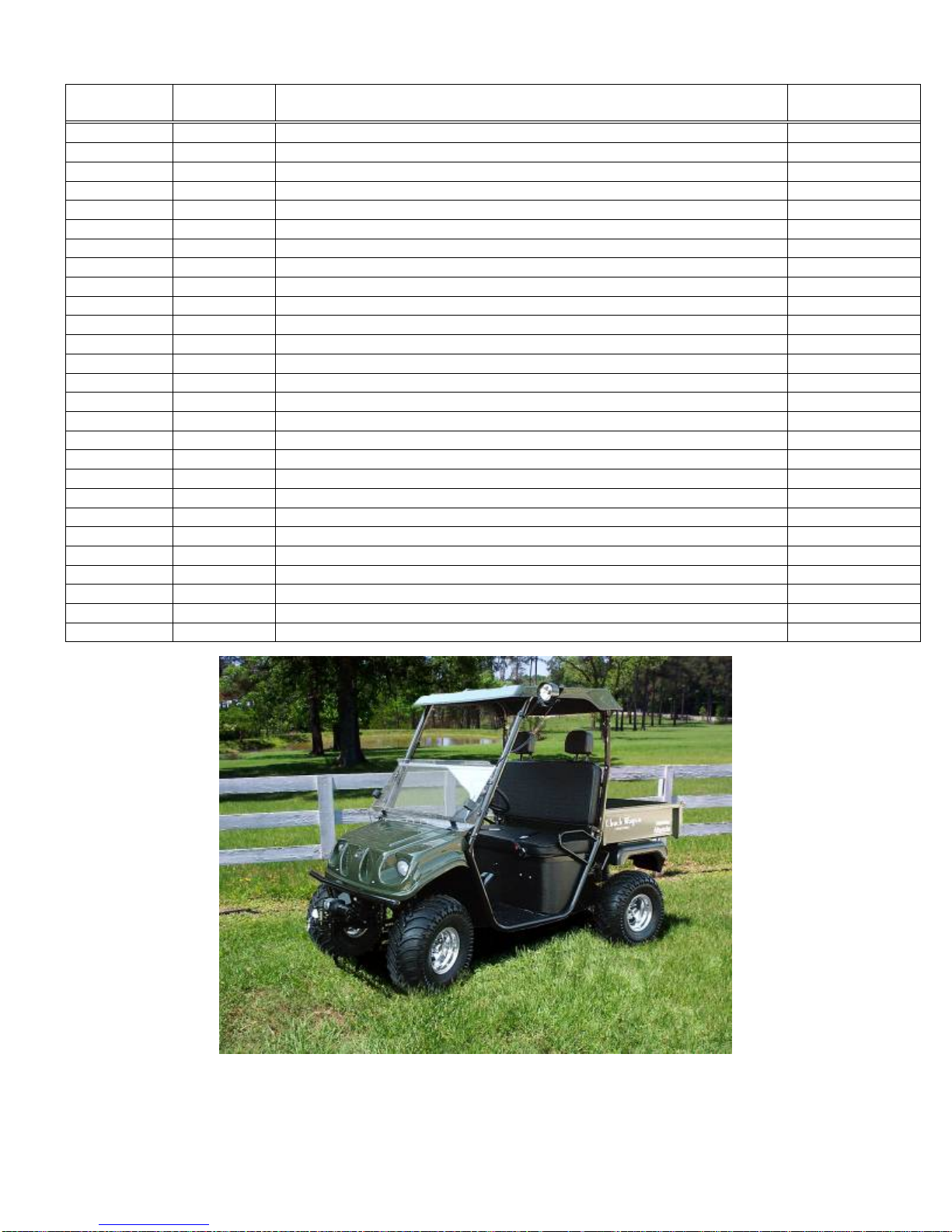
Reference
Number
133 11804 Spring #80704 Black painted 1
136 65500 fuel hose 3/16" dia - 24" 1
137 50849 hose clamps - small 3
138 18313 Belt Guard Plastic UTV - Front 1
139 18314 Belt Guard Plastic UTV - Rear 1
140 18315 Belt Guard Plastic UTV - Bottom 1
50624 #10 x 3/4" Blunt Point Black 7
50050 #10 Speed Nut - for Plastic 7
50770 #10 Flatwasher 7
141 20011 Choke Bracket Honda Engine 1
150 25004 right angle gearbox 1
10184 Key, 3/16 x 1 3
151 20852 gearbox coupling 1
152 18042 Gear box bracket “torque arm” (long) built before 10-06 1
18083 Gear box bracket (short) built after 10-06 1
70232 rubber washer - built before 10-06 2
50163 bolt, 5/16 x 3/4" NC 4
50701 Washer, 5/16 flat 6
50703 Washer, 5/16 lock 2
50005 Nut, 5/16 keps 2
50303 Bolt 7/16 x 1 3/4" - built before 10-06 1
50794 Washer, 7/16 flat - built before 10-06 2
50028 Nut, 7/16 nylock - built before 10-06 1
153 18032 diff lock mount 1
50163 bolt, 5/16 x 3/4" NC 2
50701 Washer, 5/16 flat 2
50703 Washer, 5/16 lock 2
Part
Number
Part Description – 4x4models
Quantity
Required
Accessories Available call 1-866-646-5278
BRISTER’S DESIGN & MANUFACTURING CO., LLC.
64
Page 65

ONE (1) – YEAR
LIMITED PRODUCT WARRANTY
This warranty applies to defects in workmanship or materials only.
No other warranty expressed or implied exists.
Brister's Design & Mfg LLC warrants its products with the following conditions:
Warranty Coverage: If, within one 1-year of the original date of purchase, any defects in
workmanship or materials appear in the product, Brister's Design & Manufacturing LLC will repair
or replace, at its sole option, any defective product. Only an authorized dealer or the manufacturer
(BDM) determines the existence of a warranty defect, damage or abuse to the product.
Exclusions: This warranty does not apply to normal wear & tear or minor mechanical
adjustment. This limited warranty does not apply to component failure or structural damage
caused by any of the following: collision; neglect; abuse; abnormal strain or stress; improper
assembly or improper maintenance. Any repairs or modifications made to the product in question
by anyone other than the authorized dealer or authorized service center voids the product
warranty.
Engines: This BDM warranty does not apply to the engine, which is covered by its manufacturer’s
warranty. Please refer to the engine manufactures warranty policy included with your BDM
product.
American Honda Motor Co, Inc. (770)-497-6400 Phone Two-Year Limited Engine Warranty
Warranty Service: To obtain warranty service you must return your BDM product to the local
authorized dealer, you must inform them of your warranty problem and provide proof of purchase
before any warranty service is provided. The authorized dealer will inspect the product to
determine what warranty repairs or parts are needed and if the problem meets the requirements of
BDM’s One (1) - year Limited Warranty Policy. To locate the authorized dealer nearest you please
call BDM customer service at 1-866-646-5278 or (985)-748-4889, or visit our website at
www.bristers.com for more information.
This One (1) - Year Limited Warranty in not transferable and can only be used by the
original owner. Warranty registration and dealer setup forms must be completed and
returned to BDM within 10 days of the purchase date to validate factory warranty.
Always read, view and follow the recommended service instructions.
found in your owners’ manual
Brister’s Design & Manufacturing Co, LLC.
P.O. Box 649
Roseland, LA 70456-0649
Effective 11-1-06
65
Page 66

Service and Warranty
Special Note
Should your Brister’s product require warranty repair, service or if you
have any questions concerning assembly, replacement parts or how to
care for your product please contact your local Brister’s dealer or Brister’s
Design & Manufacturing directly.
Brister’s Dealer:
To locate the authorized dealer nearest you please call Brister’s Design &
Mfg. customer service at 1-866-646-5278 or (985)-748-4889, visit our website
at
www.bristers.com or contact your place of purchase.
Mail:
Customer Support
c/o Brister’s Design & Manufacturing Co., LLC.
P.O. Box 649
Roseland, LA 70456-0649
Telephone:
Customer Support
Brister’s Design & Manufacturing Co., LLC.
1-866-646-5278 or (985)-748-4889
Fax:
Customer Support
Brister’s Design & Manufacturing Co., LLC.
1-866-329-5278 (fax) or
(985)-748-4877 (fax)
e-mail:
Customer Support
Brister’s Design & Manufacturing Co., LLC.
66
Page 67
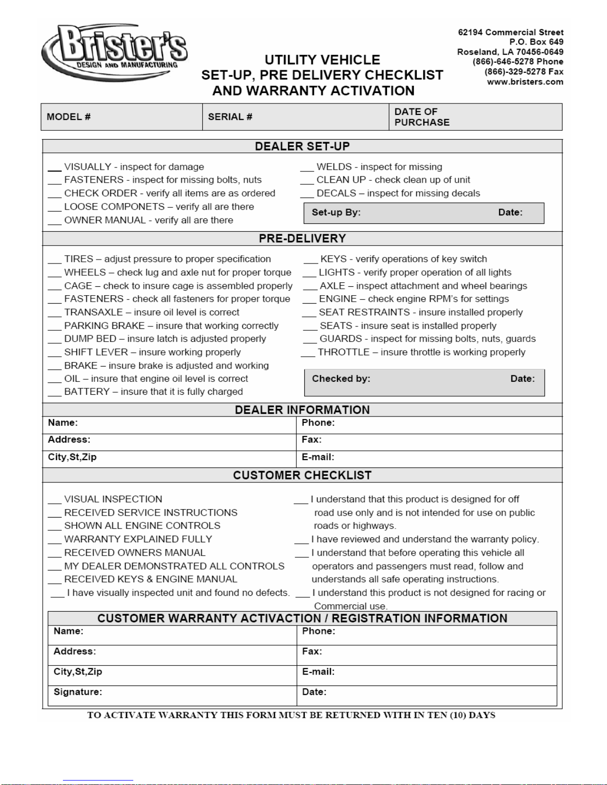
67
Page 68

68
 Loading...