

Page 1
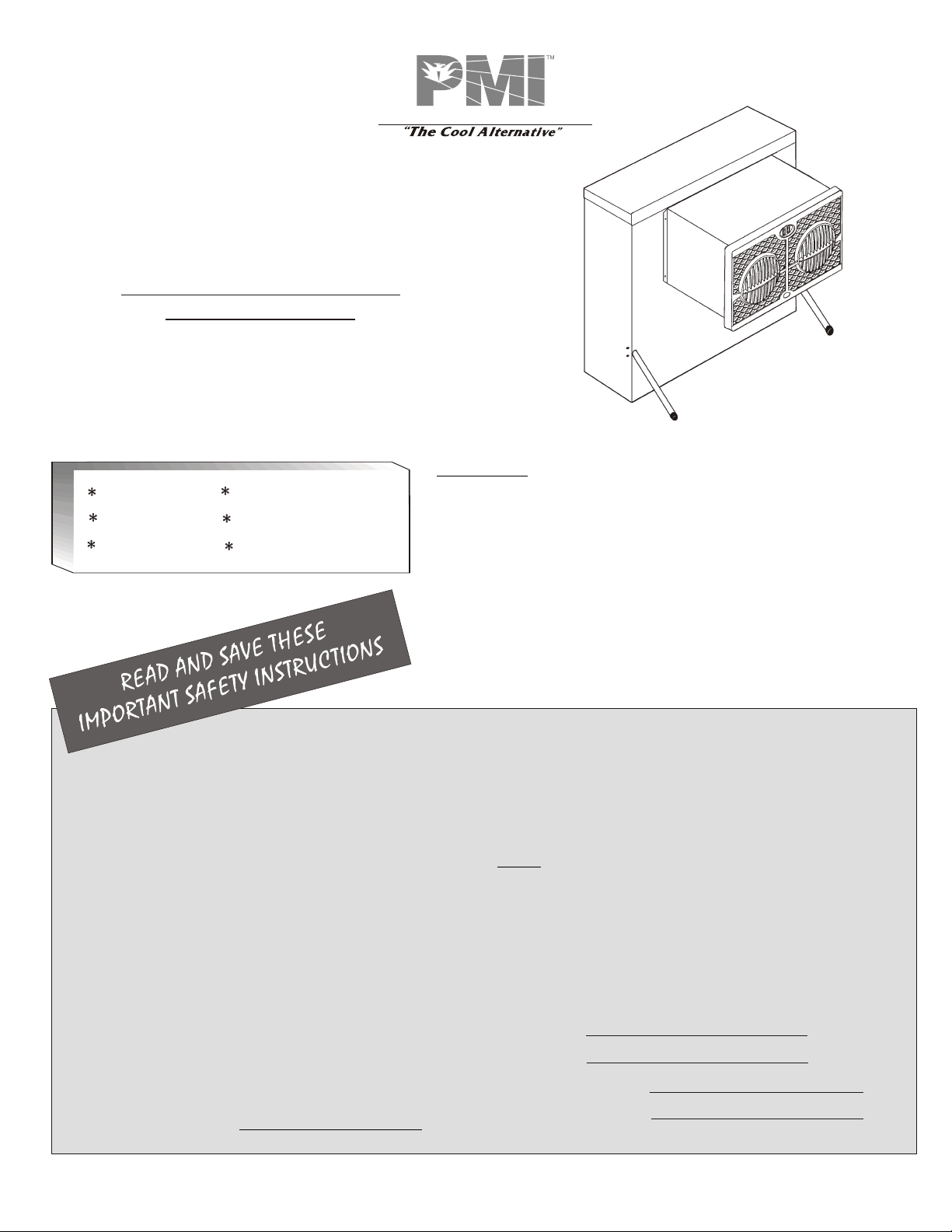
PHOENIX MANUFACTURING, INC.
OWNER’S GUIDE
USE AND CARE MANUAL
WINDOW COOLER MODEL
WH2906 & HE2913
For Customer Assistance
CALL 1-800-325-6952
DO NOT RETURN TO PLACE OF PURCHASE!
Congratulations: You have purchased a product of superior performance and design,
Safety
Installation
Start-up
Operation
Maintenance
Trouble Shooting
which will give the best service when properly installed, operated and maintained.
This guide will provide you with information needed to mount, operate, inspect, maintain,
and troubleshoot your window evaporative air cooler.
The first section, Installation and Start-Up, gives details for installation. The second
section, Maintenance, contains operational and maintenance instructions, while
Troubleshooting includes information on commonly encountered problems.
INSTALLER: Please deliver this guide to owner.
WARNING - TO REDUCE THE RISK OF FIRE, ELECTRIC
SHOCK, OR INJURY TO PERSONS, OBSERVE THE FOLLOWING.
Read all instructions carefully before installation.
This cooler must be connected to 120 Volt AC, 60 Hz (cycle)
power only. NOTE: Improper voltage will void the pump
and/or motor warranties and may cause serious personal
injury or property damage.
This cooler must be plugged into a GFCI protected
receptacle, which has been properly installed in accordance
with all local and national codes. If you are not sure that the
receptacle is GFCI protected, consult with a qualified
electrician.
This cooler is equipped with a power cord having an
equipment grounding conductor and grounding plug. Do not
attempt to defeat this safety device by removing the
grounding pin.
Use of an extension cord is not recommended.
Do not operate if plug or cord is damaged in any way. If the
unit is damaged or malfunctions, do not continue to operate it.
Always disconnect electrical power to unit before attempting
to work on or service your cooler.
Pump water tube has a restricting orifice to assure proper
water flow rate to the pad. Do not remove this restrictor!
Remove the plug from the electrical receptacle by pulling on
the plug and not the cord.
Do not operate this blower (fan) motor with any solid-state
speed control device.
Do not operate this unit with pad frame or air outlet grille
removed, this may cause the fan motor to overload and
damage the motor.
NOTE:
Do not locate unit near exhaust or vent pipes as odors or fumes
may be drawn into cooler.
Use of anode devices, chemical additives or treatments in this
cooler will void the warranty.
Your warranty does not cover shipping damage. Report all
shipping damage at once to dealer or carrier making the delivery.
For future reference, record the model and serial numbers, date
and place of purchase of your evaporative cooler here:
Model #
Serial #
Date of Purchase:
Place of Purchase:
1-999-2461 Date: 10/13
Page 2
INTRODUCTION
This manual is your guide to proper installation procedures along with
information about reasonable care and maintenance that will ensure
safe, economical and trouble free cooling. Failure to follow these
instructions may damage your cooler, impair its operation, create the
potential for serious personal injury and/or void the warranty.
Read it carefully.
A Note About Air Exhausting / Maximum Cooling
Since coolers function best when there are plenty of openings for the
air to exhaust, you can leave doors or windows open so your house
can breathe.
keep insects, dust, dirt, etc out of the cooled space, the house should
be maintained at a slightly positive air pressure (there should be
slightly more air going into the house than is leaving). This is controlled
by how much the windows or doors are opened.
How much should you open your windows or doors? You should
adjust your openings until the air pressure inside the house is
nearly balanced with the air outside. A good method to determine
when the air is reasonably balanced is to place a tissue paper
against the screen in the window or door farthest from the cooler
and adjust the other openings in the house until the tissue paper
stays lightly on the screen. You can adjust different windows in the
house to direct the most airflow to the areas that are occupied
during different times of the day or night (example: living room
windows during the daytime, bedroom windows at night.)
To get the maximum capacity of your cooler, and to help
INSTALLATION
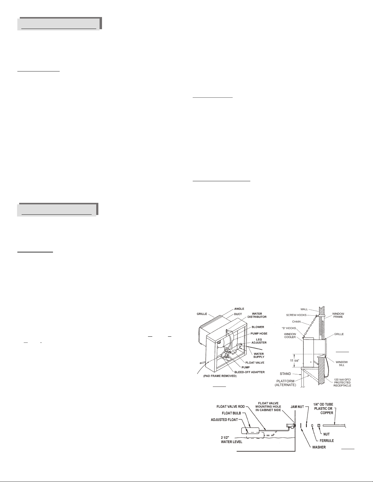
Carefully read the contents of this manual and review the
drawings of the cooler (Fig. 1 & 2) to familiarize yourself with the
various parts before beginning the installation process.
CAUTION: Disconnect all electrical power to the cooler
before attempting to install, open, or service your cooler.
Even while routinely inspecting or servicing the inside, the cooler can
be accidentally started. Keep people and pets away from the cooler
and electrical supply when you are working on it. Before opening,
servicing or cleaning the unit, unplug the unit from the wall receptacle
and take steps to ensure that the cord cannot be plugged back in and
the cooler turned on accidentally. Do not plug power cord into the wall
receptacle until installation or service work is complete.
Mounting the Cooler
Installation normally involves locating the unit in a suitable window
and using the included chain mounting kit or the construction of a
platform or stand to support the weight of the cooler. Since every
installation is different, the exact requirements to mount and seal a
cooler against the weather will be best determined by the location and
the time of the installation. Most installations will require blocking of
the unused portion of the window around the duct, or other
modifications to the window frame may be necessary.
illustration (Fig. 2) for a typical installation.
Chain mounting:
Remove pad frame from cooler.
Position the cooler so that the duct rests on the window sill and the
grille angle flanges are inside the window opening. Using a
adjustable wrench, adjust the legs firmly against the wall to level
the cooler and to hold it in place.
Attach the 2 screw hooks to the top of the outside window frame.
Attach one end of each chain onto each hook.
Insert “S” hooks into holes in the top rear corner of the cabinet,
using the hooks to pierce the vinyl hole cover (2 places).
Connect the “S” hooks to the chain so the cooler is level.
Shelf or stand mounting:
Construct a platform or stand below the window, strong enough
to support the weight of the cooler (approximately 100 pounds).
Make the platform or stand mounting surface so that the height is
11 5/8” below the resting point of the cooler duct on the window sill.
Remove pad frame assembly from cooler.
Position the cooler so that the duct rests on the window sill and the
grille flanges are inside the window frame. Using a adjustable
wrench, adjust the legs firmly against the wall to hold cooler in
place. DO NOT drive nails or screws through bottom pan into
mounting surface, this will void the warranty.
Lower the window to rest on the top of the duct (vertically hung
windows) or slide window closed against side of duct (horizontal slider
windows). Block any remaining unused portion of the window opening
with a suitable blocking material (Plexiglas, solid plastic sheet, solid
wood panel, etc.). It will be necessary to seal any joints around the
duct to prevent entry of rain, dust/dirt, insects, etc. Any good quality
caulking or foam tape will work.
See
Before attempting to install the cooler, confirm that the following
preparations have been made:
This cooler must be plugged into a 120 Volt GFCI (Ground Fault
Circuit Interrupter) protected receptacle. If you are not sure that the
receptacle is GFCI protected, consult with a qualified electrician.
This receptacle should be located within 5 feet of the window
opening (cooler power cord is 6 feet long, use of extension cords is
not recommended).
Install cooler in a window where only fresh outside air can enter.
Avoid installing the cooler in an area where the free air movement
around and into the cooler is restricted or locations where
obnoxious odors or fumes may be drawn into cooler from vent
pipes, kitchen exhausts, etc.
Verify that the supporting surface is strong enough to bear the
weight of the cooler when in use. This unit will weigh approximately
100 pounds when operating at full capacity.
Verify that the supporting surface is level in all directions.
2 Evaporative Window Cooler - Use and Care Manual
Fig. 2
Fig. 1
Fig. 3
Page 3
Connect Water Supply
CAUTION: All plumbing installations must comply with
local building and safety codes, and must be performed by
qualified personnel only.
NOTE: Coolers should not be connected to “soft” water systems. Soft
water will accelerate corrosion and decrease the effective life of the
pad and the cooler cabinet. Connect water line as follows:
A water supply valve should be installed at a convenient location,
to allow the water supply to be turned on and off for servicing or
winterizing. Minimum 1/4“ diameter tubing should be used to
provide water to the cooler, larger tubing is recommended if the
distance from the valve to the cooler is greater than 100 feet, then
reduced to 1/4” at the unit.
Install float valve in the cabinet as shown in Figure 3.
Connect tubing from water supply to float valve. Place
compression nut and ferrule over end of tubing, insert tube into
float valve then tighten compression nut to secure.
Turn on water supply and check for leaks. Adjust float to maintain
the water level at 2” to 2 ½”.
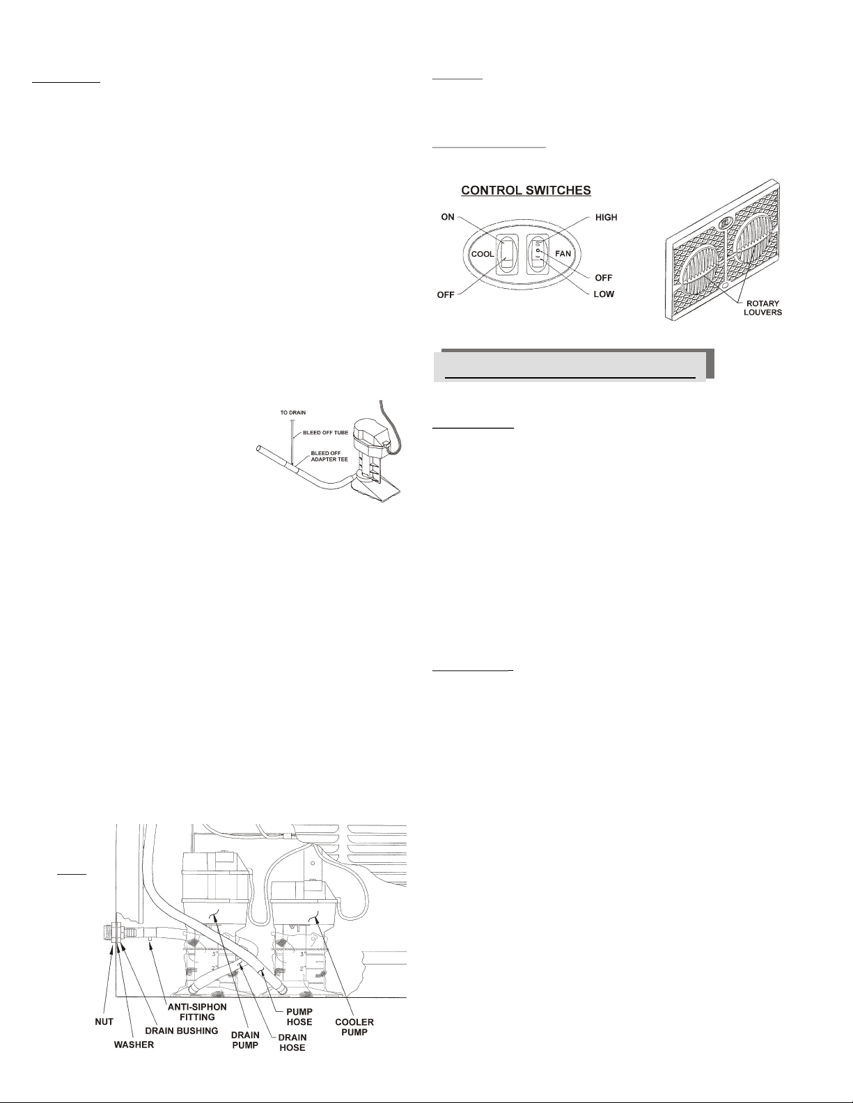
Install Bleed-off (Model WH2906)
To minimize mineral scale “build-up”,
use the included bleed-off assembly.
Remove the cap from the bleed-off tee;
insert the 1/4” diameter black tubing
and route the tubing through the 7/16”
hole in the side of the cooler opposite of
the float valve. Run bleed-off tubing to a
proper drain To prevent siphoning of
the water, make sure t at the bleed-off
tee is above the water level.
NOTE: Drain water in accordance with local plumbing codes.
.
h
Install fitting for drain pump (HE2913)
To minimize mineral scale “build-up”, these window cooler models
include an automatically timed drain pump for removing mineral laden
water from the cooler pan. It is factory set to operate every 8 hours of
unit operation in the “COOL” mode and will run for 5 minutes. Install
the drain bushing for the auto-dump drain pump discharge hose in the
side of the cooler as follows: (See figure 4)
Locate drain hose assembly in bottom of cooler and remove lock
nut from drain bushing (leave rubber washer in place). Check that
the opposite end of the hose is still connected to the drain pump.
Push drain bushing through hole in side of cooler (opposite of float
valve), rotate hose until anti-siphon fitting tube is pointing toward
bottom of cooler, then assemble and tighten lock nut.
Connect a suitable drain line (garden hose, etc) to the drain
bushing. Never drain water onto a sidewalk or other hard surfaced
area; mineral build-up or a slipping hazard may occur.
Fig 4
Cooler Operation
Controls:
The rocker control switches are used to select the operating mode
of the window cooler. These switches control fan speed (HI / OFF /
LOW) and the cooling operation (ON / OFF).
Grille airflow control:
Rotate each louver ring until desired air flow direction is reached.
GENERAL INSPECTION
Initial Start-up or Annual Inspection
CAUTION: Disconnect all electrical power to the cooler
before attempting to install, open, or service your cooler.
Before start-up of the cooler for the first time, or at the beginning of
each cooling season, make sure that all required connections,
adjustments, etc. have been made. Verify that:
P Cooler mounting is level; window duct is sealed.
P Power supply cord is correctly routed, safe and secure.
P Bleed-off / drain pump is correctly installed and fully functional.
P Water line securely connected, turned on, no leaks noted.
P Float valve is correctly installed, adjusted for proper water level
and fully operational.
P Pump impeller turns free and smooth. If in doubt, remove
impeller cover (see “Cleaning Pump”).
P Blower wheel turns freely.
Start-up Check List
CAUTION: Never operate cooler with pad frame(s) or air
outlet grille removed. This will result in an overloaded
condition and may damage the blower motor.
To verify and check out the cooler installation on initial or annual startup, the following procedure should be followed.
P Open building exhaust / relief vents (windows, doors, etc.)
P Plug supply cord into receptacle. Switch “COOL” to “ON”.
P Verify that the pump starts and pad evenly wets.
P Switch “FAN” to “HIGH”, observe that motor starts and runs.
P Switch to “LOW”, observe that motor changes to low speed.
In case of trouble on any of these steps, refer to the Troubleshooting
Chart on
Cabinet Inspection Checklist
After initial start-up and for a few weeks afterwards, check for and/or
observe the following: Refer to the Troubleshooting Chart on f
necessary.
P Leaks from water lines, pad frame, cabinet, etc.
P Cooler pad: even wetting, no dry streaks.
P Confirm water level depth setting is correct.
P Verify full, even flow in water distribution system.
P Blower wheel rotates freely, no unusual noises.
P Check motor mounting, cabinet hardware, setscrews on blower
page 6.
page 6 i
wheel are tight.
Evaporative Window Cooler - Use and Care Manual 3
Page 4
MAINTENANCE SCHEDULE
Cleaning Water Pump & Hose
Regular maintenance and periodic inspection is the key to long and
successful service from your cooler. The cooler should receive major
servicing at least once a year, more often if conditions require (dusty
environment, constant use, poor water quality, etc.) For maximum
cooling efficiency, long life and appearance, every two months during
operation, the cooler should be inspected and cleaned.
NOTE: Do Not Undercoat the Water Reservoir
Your cooler's water reservoir is finished with our Peblar XT®
appliance-type finish. It is so hard that asphalt-type cooler water pan
under-coatings will not stick to it. Undercoating will break free,
clogging the pump and water distribution system.
NOTE: Do not use cooler cleaners, cooler treatments, anodes or other
chemical additives in this evaporative cooler. Use of any additives or
water treatment other than the furnished bleed-off will void your
warranty and may impair the life of the cooler.
Before starting any maintenance operation, thoroughly read all
operating and maintenance instructions and observe all
cautions and warnings.
Cleaning
CAUTION: Never wash your cooler cabinet with a
garden hose; water may harm motor and pump or seep
inside the house through the window duct. Motors
damaged by water are NOT covered under warranty.
All foreign materials, mineral scale, hard water deposits, dirt, etc.
should be removed from pad frame, water pan and other components.
Your cooler's long lasting finish can be brought to like-new condition
by using warm water and a soft cloth.
NOTE: Avoid using scouring pads, steel wool or wire brushes, as
these will damage the finish and encourage corrosion.
Maintenance & Inspection
IMPORTANT: Before operating cooler at the beginning
of each cooling season, turn blower wheel and pump
motor shaft by hand to make sure they turn freely. Failure
to do so may result in burning out motor.
For maximum efficiency, every two months during operation, or any
time the cooler is opened, the cooler should be inspected. Some
suggested items to look for:
P Check for leaks from pad frames, cabinet, etc.
P Any dry spots or streaks on pads when pump is operating?
P Are the bearings, etc., making any unusual noises?
P Does the blower wheel turn freely?
P Is float level set correctly?
Draining
Drain the cooler for cleaning or at the end of the season as follows:
Push “COOL” and “FAN” switches to the “OFF” position. Turn off
water supply to cooler.
Remove the pad frame assembly and disconnect the pump hose
from the water distributor (located at the inside top of the cooler.
Place end of hose outside of unit for draining, keeping in mind the
amount of water to be discharged.
Turn cooler pump on by pushing “COOL” switch to the “ON”
position, pumping water out of cooler pan. Switch pump “OFF”
when no more water can be pumped out. Unplug cooler power
supply cord from wall receptacle.
Remove any remaining water with a sponge or rag.
Replace pump hose on water distributor, reinstall pad frame
assembly into cooler.
CAUTION: Disconnect all electrical power to the cooler
before attempting to install, open, or service your cooler.
CAUTION: Do not allow pump to fall over and become
submerged; water will damage pump motor.
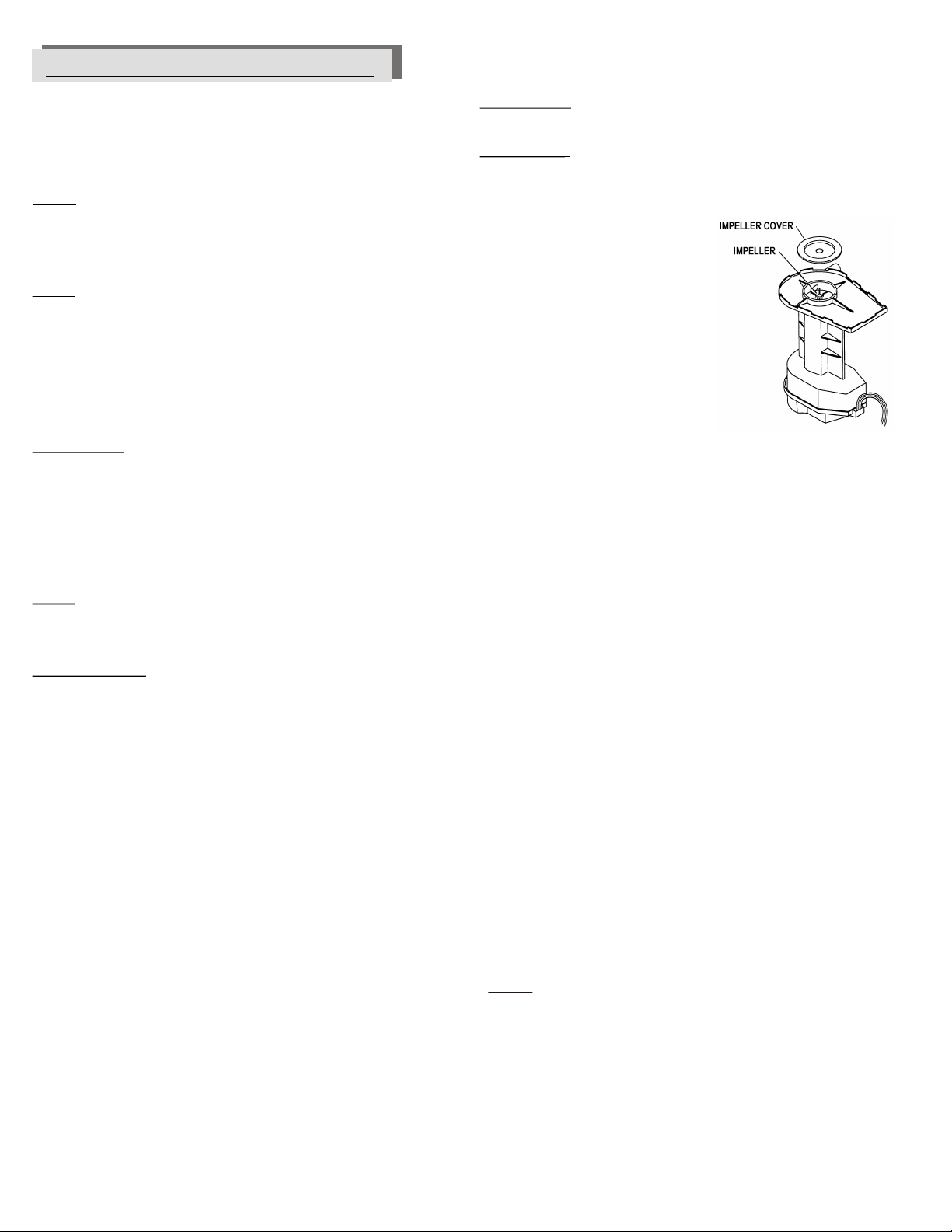
Clean water pump and hose assembly as follows:
Unplug power supply cord from
wall receptacle, remove pump
mounting bracket screw and
gently lift pump from cooler.
Shake gently to remove water.
To prevent breakage, carefully
release the snap-out impeller
cover plate and remove cover
plate from the pump body.
Using a mild detergent solution and a
soft cloth, clean deposits from screen,
around impeller and cover plate. Spin
impeller to dislodge any remaining
foreign material.
Remove any foreign material in the hose adapter
(between the pump and hose), or between the hose
and the water distributor assembly.
Rinse and reinstall impeller cover plate.
Reinstall pump and reconnect power cord.
Touch-Up
The hardness, adhesion and smoothness of the internal and external
finish on your cooler makes it extremely unlikely that scratches or
chipping will occur. In the event that finish damage does occur, it
should be promptly repaired by the following procedures:
1. Sand the area around bare metal spots.
2. Prime and paint with a quality paint.
Do not use asphalt type cooler undercoat material in water
reservoir. Undercoat will break free, clogging the pump and
water distributor.
Lubrication
Blower Motor and Pump Motor Bearings
The blower and pump motor bearings do not require lubrication.
Grille Cover
Model HE2913 is supplied with a grille cover. This cover is used
during periods of non-use or for winterizing your cooler.
Flexible tabs on each side hold the cover in place over grille. Pull side
tabs out and forward to install or to remove cover from grille.
Winter Shut Down
- Always drain all of the water out of the cooler and water supply line
when not in use for prolonged periods, and particularly at the end of
the season. Keep the water line disconnected from both the cooler
and the water supply so it does not freeze.
- Disconnect power from cooler during extended periods of non-use.
REPLACEMENT PARTS
When ordering replacement parts, always refer to the serial and
model number of your cooler. Use the part numbers listed in the
accompanying parts list, as illustrated in the diagram for your model.
4 Evaporative Window Cooler - Use and Care Manual
Page 5

Changing Cooler Pad (Model WH2906)
Changing Cooler Pad (Model HE2913)
CAUTION: Disconnect all electrical power to the cooler
before attempting to install, open, or service your cooler.
Your cooler pad should be changed at least twice a year… at the
beginning of and midway through a season . However, your pad may
need to be changed more frequently, depending on local air and water
conditions. For instance, in areas where mineral content of the water
is high, deposits may build up in the cooler pad, restricting airflow.
Replace pad as follows:
Remove pad frame assembly from cabinet.
Remove pad retainer from frame, using caution as retainer can
spring back. Carefully remove all aspen from pad frame. Remove
and discard old pad.
Using a mild detergent, wash dirt and scale from pad frame and
rinse with fresh water. Wire brushing is not recommended. If finish
is damaged or rusting is noted, repair area as noted in the “TouchUp” section.
Lay new pad in frame, starting at trough end, making sure pad is
snug against trough and outer edges with no air spaces. Pad must
completely fill frame (no gaps) or hot air may enter building.
Pad thickness should be uniform across the frame.
Replace pad retainer and lock under edge of frame. Sharp points
must be buried into pad (they hold pad in place and prevent
sagging).
Pre-soak pad and check for air gaps along edges, reinstall pad
frame assembly into unit.
CAUTION: Disconnect all electrical power to the cooler
before attempting to install, open, or service your cooler.
The condition of your cooler pad should be checked at least once a
year; at the beginning of the season is best. However, your pad may
need to be checked more frequently, depending on local air and water
conditions. For instance, in areas where mineral content of the water
is high or the air is dusty, deposits may build up in the cooler pad,
restricting airflow. Clean or replace pad as follows:
Remove pad frame assembly from cabinet.
Lay pad frame on smooth, flat surface with pad retainer up.
Observe the location / placement of the pad retainer. Remove
retainer by sliding it out from under the pad frame flange. Carefully
remove and discard old pad.
Using a mild detergent, wash dirt and scale from pad frame and
rinse with fresh water. Check slots at top of pad frame to be sure
they are open and clear. Wire brushing is not recommended. If
finish is damaged or rusting is noted, repair area as noted in the
“Touch-Up” section.
Place the slot in the end of the new pad over the bottom flange of
the pad frame and push the pad down against the flange until it
stops. Gently push the top of the pad into the pad frame. Slide the
1” thick pad on top of the large pad already in place. Replace the
pad retainer by sliding the retainer under the pad frame flanges .
Pre-soak pad (this will help with the wetting of the pad on start-up) .
Reinstall pad frame assembly into unit.
MODEL WH2906
WIRING DIAGRAM
MODEL HE2913
Evaporative Window Cooler - Use and Care Manual 5
Page 6

TROUBLESHOOTING GUIDE: Should an obvious problem occur with your cooler consult the following table. If you
cannot correct the problem, or if it persists, contact qualified service personnel.
PROBLEM / SYMPTOM
Water draining from unit
Dry pads
Motor does not start or no air delivery
Inadequate air delivery
Motor cycles on & off
Noisy operation
Excessive humidity in house
POSSIBLE CAUSE
Float valve out of adjustment
Float movement obstructed
Non-functional float valve
Pump intake clogged
Non-functional water pump
Clogged water line
Pad trough clogged
Non-functional switch
Non-functional wiring
Water turned off to cooler
Electrical power disconnected
Circuit breaker tripped or fuse blown
Non-functional motor
Non-functional switch
Insufficient air exhaust
Blower wheel loose on motor shaft
Pads clogged
Low voltage
Motor shaft tight or frozen
Pad frame or air outlet grille removed
Blower rubbing on housing
Motor or blower mounting screws loose
Inadequate exhaust
CORRECTIVE ACTION
Adjust float to 2 1/2“ water depth
Free float from obstruction
Replace float assembly
Remove obstruction
Replace water pump
Locate and free obstruction
Clear debris from trough
Replace switch
Repair or replace non-functional wiring
Turn on water supply
Check power receptacle and cord
Determine cause and correct
Replace motor
Replace switch
Open windows to increase air flow
Tighten wheel set screw
Replace pads
Check voltage
Replace motor
Re-install pad frame or air outlet grille
Reposition wheel
Tighten screws
Open doors and windows to increase ventilation
6 Evaporative Window Cooler - Use and Care Manual
Page 7

PHOENIX MANUFACTURING, INC.
GUÍA DEL PROPIETARO
MANUAL DE USO Y CUIDADO
ENFRIADOR EVAPORATIVO de VENTANA:
Modelo WH2906 & HE2913
Para Asistencia al Cliente
LLAMAR 1-800-325-6952
NO REGRESARLO A LUGAR DE COMPRA!
Felicitaciones: Usted acaba de comprar un producto de superior rendimiento y diseño, que la
dará el mejor servicio cuando sea propiamente instalado, operado y mantenido.
Seguridad
Instalación
Incio
Operación
Mantenimiento
Trazando Fallas
Este manual fue diseñado para proporcionarle a usted y a su instalador la información necesaria
para montar, operar inspeccionar, mantener y encontrar cualquier falla en su enfriador.
La primera sección de Instalación e Inicio, es especialmente para el instalador. La sección
segunda, Mantenimiento, contiene instrucciones de operación y mantenimiento para el
propietario, mientras que la sección de Detección de Problemas incluye información sobre los
problemas mas comunes.
INSTALADOR: Favor de entregar esta guía al propietario.
T S
ES
E
V
R
E
S
ON A
C
Y
A
E
L
U
R C
ST
N
Lea estas instrucciones cuidadosamente antes de instalar, operar o dar
servicio a la unidad.
Este enfriador debe ser conectado a una fuente de 120V c.a. 60 ciclos
solamente. NOTA: voltaje impropio anulará la garantía del motor y/o la
bomba y podría causar serias lastimaduras personales o daños a la
propiedad.
Este enfriador debe ser enchufado a un receptáculo protegido con
GFCI, que ha sido propiamente instalado con todos los códigos locales
y nacionales. Si no tiene seguridad que el receptáculo no está
protegido con GFCI consulté con un electricista competente.
Este enfriador viene equipado con un cordón con conductor y clavija de
tierra para el equipo. No trate de anular el dispositivo de seguridad
removiendo la clavija de tierra.
No se recomienda el uso de extensiones eléctricas
No lo opere si el cordón o la clavija están dañados en cualquier forma.
Si la unidad está dañada o funciona mal, no continue operándola.
Siempre desconecte la corriente eléctrica de la unidad antes de
trabajar o darle servicio a su enfriador.
La manguera de agua tiene un restrictor con orificio que asegura el flujo
de agua propio para el filtro. No removerlo!
RT
P
M O N E
N
O
I E
C
A T
R DA
E S
D
I
S
SI
EG
D
I
U
ADVERTENCIA - PARA REDUCIR EL RIESGO DE INCENDIO,
DESCARGA ELÉCTRICA O LASTIMADURAS A PERSONAS, OBSERVE LO SIGUIENTE:
Remueva el cordón del receptáculo eléctrico jalando de la clavija y no el
cordón.
No opere el motor de la turbina con dispositivos transistorizados para
controlar la velocidad.
No opere la unidad sin el filtro y/o la rejilla de aire, esto puede causar
que se sobrecargue el motor y dañarlo.
NOTA:
No instale el enfriador cerca de extractores o tubos de ventilación ya que
olores o vapores pueden ser inducidos en la unidad.
El uso de ánodos, aditivos químicos o tratamientos en esta unidad anulan
la garantía.
Su garantía no cubre daños de envío. Reporte cualquier daño de envío de
inmediato al distribuidor o al transportador realizando la entrega.
Para futura referencia, anote el modelo, número de serie, fecha y lugar de
compra de su enfriador evaporativo:
Modelo #:
Serie #:
Fecha de Compra:
Lugar de Compra:
1-999-2461 Date: 10/13
Page 8

INTRODUCCIÓN
Ester manual es una guía de procedimientos para una instalación
propia junto con información de un cuidado razonable y
mantenimiento que le asegurará un enfriamiento seguro, económico
y sin problemas. El no seguir estas instrucciones puede dañar su
enfriador, incapacitar su operación, crear un potencial para una seria
lastimadura personal y/o anular la garantía. Lea cuidadosamente
Notas para Salidas de Aire / Enfriamiento Máximo
Ya que los enfriadores funcionan mejor cuando el escape de aire es
en abundancia, usted puede dejar puertas o ventanas abiertas para
que su casa pueda respirar. Para obtener la capacidad máxima de su
enfriador, y ayudar a mantener insectos, polvo, tierra, etc fuera del
espacio enfriador, la casa debe mantenerse ligeramente a una
presión positiva (aire entrando la casa sea más que el que sale)
se controla con que tanto se abran las ventanas y puertas.
¿Que tanto debe habrir sus ventanas o puertas? Debe habrir sus
aberturas hasta que el aire dentro de la casa casi se balance con el
aire de afuera. Un metodo usado para determinar si el aire esta
razonablemente es el de poner un pedazo de papel en contra del
alambre mosquitero de la ventana más lejana al enfriador y ajustar
la abertura de las ventanas hasta que el papel se quede
lijeramente en el alambre mosquitero de la ventana. Usted puede
ajustar diferentes ventanas en la casa para dirigir más flujo de aire
a las areas que estén ocupadas durante diferentes tiempos del día
o la noche (ejemplo: ventanas de la sala durante el día, de la
recámara durante la noche)
Esto
INSTALACION
Cuidadosamente lea los contenidos de este manual y revise los
planos del enfriador (Fig. 1 y 2) para que usted se familiarize con
las varias partes antes de comenzar el proceso de instalación.
PRECAUCION: Desconecte toda la corriente eléctrica
del enfriador antes de intentar instalar, abrir, o darle
servicio a su enfriador.
Aún cuando rutinariamente se inspeccione o de servicio al interior, el
enfriador puede empezar accidentalmente. Mantenga todo el
personal alejado del enfriador y suministro de corriente al trabajar en
él. Antes de darle servicio o limpiar la unidad, desenchufe la unidad
del receptáculo de la pared y asegurese que el cordón no sea
enchufado de nuevo y el enfriador prenda accidentalmente. No
enchufe el cordón en el receptáculo hasta que la instalación o trabajo
de servicio esté completo.
Antes de intentar instalar el enfriador, asegúrese que las
siguientes preparaciones se hayan hecho:
Este enfriador tiene que ser enchufado a una fuente de 120 voltios con
receptáculo protegido con GFCI (Interruptor de Circuito a Falta de Tierra). Si usted
no está seguro si el receptáculo tiene protección GFCI, consulte con un
electricista competente. Este receptáculo debe estar situado entre una distancia
de 5 pies de la abertura de la ventana. (El cordón de suministro es de 6 pies de
largo, el uso de una extensión no es recomendable).
Asegúrese que la superficie de soporte es lo suficiente fuerte para soportar el
peso del enfriador cuando esté en uso; recuerde cuando el depósito está lleno de
agua, el enfriador pesará mucho más que vacío.
Instale enfriadores en un ventana donde solamente aire fresco de afuera entre de
enfriamiento. Evite el instalar las unidades en áreas que restringen el movimiento
libre del aire alrededor y la entrada del enfriador, o cerca de tubos de venteo,
extractores de cocina, etc.; ya que repugnantes olores o vapores pueden ser
inducidos por la unidad.
Asegúrese que la superficie de soporte es lo suficiente fuerte para soportar el
peso del enfriador cuando esté en uso. Esta unidad pesará aproximadamente 100
libras cuando opere en plena capacidad.
Verifique que la superficie de soporte esté nivelada en todas direcciones.
2 Enfriador Evaporativo de Ventana - Maunal de Uso y Cuidado
Montando el enfriador
La instalación normalmente envuelve el situar la unidad en una
ventana apropiada y usando el juego de cadena incluido o la
construcción de una plataforma o tarima para que soporte el peso del
enfriador. Ya que cada instalación es diferente, los requerimientos
exactos para montar y sellar el enfriador en contra del clima será
determinado por el sitio y al momento de la instalación. La mayoría
de las instalaciones requieren el cerrar la parte sin uso alrededor del
ducto, u otras modificaciones al cuadro de la vantana quizás sean
necesarias. Vea ilustración (Fig. 2) para instalación típica.
Instalacion de la cadena:
Remueva el filtro del enfriador.
Situe el enfriador de talmanera que el ducto descanse en el umbral
de la ventana y los angulos rejillas cejas esten dentro de la avertura
de la ventana. Usando una llave ajustable, ajuste firmemente las
piernas en contra de la pared para nivelar y detener el enfraidor en
su lugar.
Atornille los 2 ganchos roscados en el marco superior afuera de la
ventana. Enganche el extremo de cada cadena a cada gancho.
Cocoque los 2 ganchos en “S” en los agujeros de la parte superior
trasera del giabinete en ambos lados usando el gancho para
agujerar las cuiertas de vinilo.
Conecte los ganchos en “S” a la cadena de tal manera que el
enfriador quede nivelado.
Montado en plataforma o tarima:
Construya la plataforma o tarima debajo de la ventana, lo suficiente
fuerte para soportar el peso del enfriador (aproximadamente 100
libras).
Fabrique la superficie de la plataforma o tarima de tal manera que
la altura sea de 11 5/8” debajo de el punto de descanso del ducto en
el marco de la ventana.
Remueva el filtro del enfriador.
Sitúe el enfriador de tal manera que el ducto descanse en el marco
de la ventana y las cejas de la rejilla estén dentro del armazón de la
ventana. Usando una llave ajustable, ajuste las piernas firmemente
en contra de la pared para detener el enfriador en su lugar. NO
clave clavos o tornillos a través del fondo y la superficie en que
se va a montar, esto anula la garantía.
Cierre la ventana para que descanse sobre la parte superior del ducto
(en ventanas que cuelgan verticalmente) o ventanas que se deslizan
al lado del ducto (ventanas que se deslizan hacia los lados). Bloquee
la abertura restante de la ventana con un material apropiado para el
caso (plexiglás, hoja sólida de plástico, panel sólido de madera, etc.).
Será necesario sellar cualquier unión alrededor del ducto para
prevenir la entrada de la lluvia, polvo/tierra, insectos, etc. Cualquier
sellador de buena calidad o cinta serviría para el propósito.
Fig. 2
Fig. 1
Fig. 3
Page 9

Conecte el Suministro de Agua
PRECAUCION: Todas las instalaciones de plomería
tienen que cumplir con los códigos de edificar y reglas de
seguridad, y llevadas a cabo por personal competente
solamente.
NOTA: Los enfriadores no se deben conectar a sistemas de agua
“blanda”. Agua blanda acelera la corrosión y reduce la vida efectiva de
los filtros y gabinete. Conecte el suministro de agua como sigue:
La válvula de suministro de agua podría instalarse en un sitio
conveniente, para permitir abrir y cerrar para dar servicio o
apagado de invierno. Un tubo con un mínimo de 1/4” se debe usar
para el suministro de agua hacia el enfriador, Un tubo más grande
se debe usar si la distancia es mayor de 100 pies y reducida a 1/4”
en la entrada de la unidad.
Instale la válvula del flotador en el gabinete como se indica (fig. 3)
Conecte un tubo del suministro de agua al flotador. Ponga la tuerca
de compresión y la férula sobre el extremo del tubo, inserte el tubo
en la válvula y apriételo la tuerca de compresión bien.
Abra el suministro de agua y revise si hay fugas. Ajuste el flotador
para mantener un nivel de 2” a 2 ½..
Instale el sangrado (Model WH2906)
Para minimizar la “acumulación de sarro’,
use la sangría incluida. Remueva el tapón
del adaptador “T” e inserte tubo negro y
guíelo a través del agujero de 7/16’ en el
costado opuesto a la válvula del flotador.
Recorra el tubo de sangrado hacia un
grenaje apropiado. Para prevenir sifónaje
del agua, asegure que la “T” del sangrado
esté arriba del nivel del agua.
NOTA: Drene el agua de acuerdo con los códigos locales de plomería.
Instale el aditamento para la bomba de drenaje (HE2913)
Para minimizar la "acumulación de sarro", en el modelo HE2912 enfriador
de ventana se incluye una bomba con temporizador para remover el agua
cargada de minerales del depósito. Ajustado en la fábrica para operar
cada 3 horas por 6 minutos en la operación de "COOL". Instale el buje de
drenaje para la manguera del sistema automático de drenaje en el
costado del enfriador como sigue: (ver figura 4)
Coloque el ensamble de la manguera removiendo la tuerca del buje
(dejando la arandela de hule en su lugar). Revise si el lado opuesto de
la manguera aún esté conectada a la bomba de drenaje.
Inserte el buje de drenaje através del agujero en el costado del enfriador
(lado opuesto a la vávula), girar la manguera hasta que el aditamento
anti-sifón apunte hacia el fondo del enfriador, atornille la tuerca.
Conecte una linea adecuada de drenaje (manguera de jardín, etc) al
buje de drenaje. Nunca drene el agua en la banqueta u otra area con
superficie dura: ya que con la acumulación de sarro se puede poner
resbalosa.
Fig 4
Operación de Enfriador
Controles:
Los interruptores se utilizan para seleccionar el modo de operación
del enfriador de ventana. Estos interruptores controlan la velocidad
de la turbina (ALTA / APAGADO / BAJA) y la operación de
enfriamiento (ENCENDIDO / APAGADO).
Parrillas giratorias:
Gire cada parrilla hasta alcanzar la dirección de aire deseada.
INSPECCIÓN GENERAL
Lista de inspección de pre-comienzo o anual
PRECAUCION: Desconecte toda la corriente eléctrica
del enfriador antes de intentar instalar, abrir, o darle
servicio a su enfriador.
Antes de prender el enfriador por primera vez, o en el comienzo de
cada temporada de enfriamiento, asegúrese de haber hecho todas
las conexiones y ajustes. Verifique que:
P Montura del enfriador a nivel; ductos de ventana sellados.
P El cordón clavija este correctamente guiado, seguros y
fuera de peligro.
P Sangrado o bomba de purga están correctamente
instaladas y funcionales.
P Línea de agua seguramente conectada, abierta, sin fugas
notables.
P Válvula del flotador están correctamente instaladas y
funcionales, ajustado al propio nivel.
P Impelente de la bomba gira libre y suave. Si hay duda
remueva la cubierta del impelente (véase “limpieza de la
bomba”) y revise la rotación.
P Turbina gira libremente.
Chequeo de empiezo
PRECAUCION: Nunca opere la unidad sin el filtro o
rejilla del aire. Esto resultaría en condición de sobrecarga
y podría dañar el motor de la turbina.
Para verificar y chequeo de la instalación del enfriador en el comienzo
inicial o anual, siga el siguiente procedimiento.
P Habrá las salidas / ventilaciones (ventanas, puertas, etc.)
P Enchufe el cordón clavija en el receptáculo de pared.
P Verifique si la bomba empezó y los filtros se mojan parejos.
P Observe comienza y funciona.
En caso de problemas en alguno de estos pasos, refiérase a la lista
de trazando fallas en página 6.
Lista de inspección del gabinete
Después del comienzo inicial y durante inspecciones periódicas,
revise u observe lo siguiente: Refiérase a la lista trazando fallas en la
página 6 si es que es necesario.
P Fugas de las líneas de agua, filtro, gabinete, etc.
P Filtro de enfriador: se mojen parejos, no áreas secas.
P El ajuste del nivel del agua sea correcto.
P Verifique el flujo de agua completo y parejo en el
sistema de distribución.
P Turbina / motor giran libremente, no ruidos extraños.
P Revise la montadura del motor, tornillos del gabinete, tornillos
opresores de la turbina apretados.
Enfriador Evaporativo de Ventana - Maunal de Uso y Cuidado 3
Page 10

LISTA DE MANTENIMIENTO
Mantenimiento regular e inspecciones periódicas son la clave de un
bueno y prolongado servicio de su enfriador. El enfriador debe recibir
servicio completo a menos una vez por año y más seguido si las
condiciones lo requieren (ambiente polvo, uso constante, calidad del
agua, etc.) Para máxima eficiencia de enfriamiento, larga vida y
apariencia, cada dos meses durante su operación, el enfriador debe
ser inspeccionado y limpiado.
NOTA: No ponerle brea al depósito de agua.
El depósito de su enfriador tiene un acabado con nuestro Peblar XT
acabado tipo artefacto. Es tan duro que la brea no se pegará al fondo.
La capa se despegará y se soltará, tapando la bomba y el distribuidor
de agua.
NOTA: No use limpiadores para enfriadores, ánodos, tratamientos u
otro aditivo químico en este enfriador. El uso de aditivos o
tratamientos para el agua u otro que no sea sangrado anulará la
garantía y perjudicará la vida del enfriador.
Antes de comenzar la operación de mantenimiento, lea
detalladamente todas las instrucciones de mantenimiento
y operación y observe todas las precauciones y
advertencias.
Limpieza
PRECAUCION: Nunca lave su enfriador con manguera
de jardín; El agua puede dañar el motor y la bomba o
infiltrada la casa a través al ducto de ventana. Motores
dañados por el agua NO los cubre la garantía.
Materiales extraños, sarro, depósitos de sal, minerales etc. Deben de
removerse de las rejillas del filtro, fondo, y otros componentes. El
acabado duradero de su enfriador se puede poner como en condición
de nuevo usando agua tibia y un trapo suave.
NOTA: Evite estropajos, estropajos o brochas de alambre, estos
dañarán él acabado estimulando la corrosión.
Mantenimiento e Inspección
Limpieza de la bomba y manguera
PRECAUCION: Desconecte toda la corriente eléctrica
del enfriador antes de intentar instalar, abrir, o darle
servicio a su enfriador.
PRECAUCION: No permita que la bomba se caiga y se
sumerja; el agua daña el motor.
Limpie la bomba, la manguera y la ensamble de distribuidor como sigue:
Desenchufe el cordón de enfriador,
remueva el tornillo de la abrazadera
de la bomba y con cuidado
la bomba del enfriador. Sacúdala
ligeramente para removerla del
agua.
Para prevenir que se quiebre, con cuidado
remueva la placa de la base del impelente y
remueva la placa de la base de la bomba.
Usando una solución de detergente ligera,
limpie los depósitos del cedazo de la bomba,
alrededor del impelente y la tapadera de la
base. Gire el impel
material ajeno.
Remueva cualquier material (ajeno en el adaptador y la
manguera), o entre la manguera y el distribuidor de agua.
Enjuague y reinstale la cubierta del impelente.
Reinstale la bomba y enchufe el cordón de enfriador.
Retocar
La dureza, adhesión y suavidad del acabado interno y externo en su
enfriador hace que sea extremadamente improbable que la pintura se
raspe o se pele. En un evento que esto ocurra, se debe reparar
siguiendo los siguientes procedimientos:
1. Lije el área alrededor de las partes de metal descubiertas.
2. Use pintura de fondo y pintura de buena calidad.
No use compuestos de asfalto en el depósito de agua ya que se
separará, tapando la bomba y el distribuidor de agua.
remueva
ente para destapar
IMPORTANTE: Antes de operar el enfriador al
comienzo de cada temporada de enfriamiento, gire la
turbina y el eje de la bomba con la mano para asegurarse
que giren libremente. El no hacerlo podría resultar en un
motor quemado.
Inspección periódica de su enfriador puede realzar la vida libre de
problemas de este. Para máxima eficiencia, cada dos meses durante
su operación, o en cualquier ocasión que habrá el enfriador, lo debe
inspeccionar. Algunas sugerencias:
P ¿Revise por goteras del filtro, gabinete, etc.
P ¿Encuentra puntos secos en la paja cuando en operación?
P ¿Sonidos extraños en las chumaceras o motores?
P ¿La turbina gira libremente?
P ¿Flotador al correcto nivel?
Drenando
Vacié el depósito para limpieza o al final de cada temporada como sigue:
Ponga el interruptor “COOL” y “FAN” en “OFF”. Cierre el
suministro de agua al enfriador.
Remueva el filtro y desconecte la manguera en el lado del
distribuidor de agua localizado en la parte de arriba del enfriador.
Use este lado de la manguera para vaciar el enfriador, fijándose en
la cantidad de agua que se va a vaciar.
Ponga el interruptor “COOL” en “ON” para bombear el agua fuera
del depósito, en “OFF” cuando el depósito esté vacio. Desenchufe
el cordón de suministro del receptáculo de la pared.
Remueva cualquier sobrante de agua con una esponja o trapo.
Regrese la manguera de nuevo al distribuidor, reinstale el
filtro en el enfriador.
LUBRICACION
Chumaceras del motor de la turbina y la bomba
Las chumaceras están permanentemente lubricadas.
Cubierta de Parrilla
Modelo HE2913 están proveído con una cubierta de rejilla. La
cubierta se usa durante períodos de no uso o apagado de invierno.
Lengüetas flexibles en ambos lados aseguran la cubierta a la parilla.
Jale las lengüetas hacia fuera y adelante para instalar o remover la
parilla.
Apagado de Invierno:
- Siempre vacie toda el agua del enfriador y de la tubería cuando no
esté en uso por periodos prolongados, y particularmente en el término
de la temporada. Mantenga la tuberia del agua desconectada en
ambos lados para que no se reviente en bajas temperaturas.
- Disconecte el enfriador de la fuente durante largos
periodos de no uso.
Reemplazo De Partes
Cuando ordene partes de reemplazo, siempre refiérase al modelo y
número de serie de su enfriador. Use él número de parte en la
acompañante lista de partes, como esta ilustrado en los diagramas de
su modelo.
4 Enfriador Evaporativo de Ventana - Maunal de Uso y Cuidado
Page 11

Cambiando el filtro (Modelo WH2906)
Cambiando el filtro (Modelo HE2913)
PRECAUCION: Desconecte toda la corriente eléctrica
del enfriador antes de intentar instalar, abrir, o darle
servicio a su enfriador.
El filtro de su enfriador se deben cambiar dos veces por año.....al
principio y a la mitad de la temporada. O cuando el filtro requieran
cambiarse más frecuentemente, de acuerdo con el aire y las
condiciones del agua local. Por ejemplo, en áreas donde el contenido
de minerales del agua es alto, depósitos se acumulan en el filtro,
restringiendo el flujo del aire.
Reemplace el filtro como sigue:
Remueva el armazón del gabinete.
Remueva el retenedor de alambre, usando precaución ya que
pueden resortear. Cuidadosamente remueva la paja de el
retenedor. Remueva y deseche el filtro viejo.
PRECAUCION: Desconecte toda la corriente eléctrica
del enfriador antes de intentar instalar, abrir, o darle
servicio a su enfriador.
Los filtros de su enfriador se deben revisar una vez por año.....de
preferencia al principio de la temporada. O cuando los filtros
requieran revisarse más frecuentemente, de acuerdo con el aire y las
condiciones del agua local. Por ejemplo, en áreas donde el contenido
de minerales del agua es alto o el aire es sucio, depósitos se
acumulan en los filtros, restringiendo el flujo del aire. Reemplace los
filtros como sigue:
Remueva el armazón del gabinete.
Coloque el armazón del filtro en una superficie lisa con los
retenedores hacia arriba. Observe como los removió / para
instalarlos de nuevo. Remueva el retenedor deslizándolo bajo la
ceja del armazón. Cuidadosamente remueva y deseche el filtro
usado.
Usando detergente ligero, lave la tierra y sarro del armazón,
enjuague con agua fresca. No se recomienda el uso de brochas de
alambre. Si se daña el acabado o nota corrosión, repare el área
como lo indica la sección de retocar.
Ponga el filtro nuevo en el armazón, empezando por el lado de la
canaleta, que ajuste con la canaleta y las orillas de los lados sin
espacios de aire, el filtro debe llenar el armazón o aire caliente
entrará al edificio.
El grosor del filtro debe estar uniforme a través del armazón.
Reinstale el retenedor de alambre y asegúrelos alrededor del
armazón. Puntos filosos metidos en el armazón (detiene el filtro en
su lugar y previene que se afloje)
Pre-remoje el filtro y revise si quedaron aberturas a lo largo de las
orillas, reinstale el filtro en la unidad.
DIAGRAMA de ALAMBRADO
MODELO WH2906 MODELO HE2913
Usando detergente ligero, lave la tierra y sarro del armazón,
enjuague con agua fresca. No se recomienda el uso de brochas
de alambre. Si se daña el acabado o nota corrosión, repare el área
como lo indica la sección de retocar.
Inserte la ranura del filtro nuevo en la parte de abajo del armazón
empujuelo hasta que se detenga. Con cuiado empuje la parte
superior del filtro hacia adentro del armazón. Inserte el pedazo de
filtro de 1” entre la canaleta y el filtro largo. Ahora inserte el
retenedor del filtro en las cejas del aramzón.
Pre-remoje el filtro (esto ayudará el que el filtro se humedezca al
comenzar) instale el filtro en la unidad.
Enfriador Evaporativo de Ventana - Maunal de Uso y Cuidado 5
Page 12

TRAZANDO FALLAS : Si un problema obvio ocurre en su enfriador, consulte la siguiente tabla. Si no
puede corregir el problema, contacte a un representante competente de servicio.
PROBLEMA / SÍNTOMA:
Derrame de agua en la unidad
Filtros Secos
No comienza o no hay entrega de aire
Entrega de aire inadecuado
El motor se prende y se apaga
Operación ruidosa
Humedad excesiva dentro de la casa
CAUSA PROBABLE:
Válvula de flotador fuera de ajuste
Movimiento del flotador obstruido
Válvula no funciona
Entrada de agua de la bomba tapada
Bomba no funciona
Linea de agua tapada
Canaleta de filtro tapada
Interruptor no funciona
Alambrado no funciona
Agua hacia el enfriador cerrada
Corriente eléctrica desconectada
Fusible quemado o disyuntor se apaga
Motor no funciona
Interruptor no funciona
Insuficiente escape de aire
Turbina floja con eje
Filtros tapados
Bajo voltaje
Eje de motor congelado
Filtro o rejilla del aire removidos
La turbina rosa con la caja del soplador
Tornillos de la turbina muy flojos
Inadecuado escape de aire
ACCIÓN CORRECTIVA:
Ajuste el flotador 2 1/2“ de profundidad de agua
Libere el flotador de la obstrucción
Remplace el ensamble de flotador
Remueva la obstrucción
Remplace la bomba
Localice y remueva la obstrucción
Limpie la basura de las canaletas
Remplace el interruptor
Repare o remplace alambres
Abrir el suministro de agua
Revisar el receptáculo de corriente y el cordón
Diagnosticar la causa y corregir el probelma
Remplace el motor
Remplace el interruptor
Abra ventanas para aumentar el flujo
Apriete tornillos de turbina
Remplace filtros
Revise el voltaje
Remplace el motor
Reinstale el filtro o rejilla
Alinear la turbina
Apriete tornillos
Abra ventanas para aumentar la ventilación
6 Enfriador Evaporativo de Ventana - Maunal de Uso y Cuidado
 Loading...