

Page 1

Page 2

Dear Valued Customer,
You have acquired a Silver edger. We would like to thank you for the
confidence you have shown in our brand.
This edger has been manufactured with the greatest care. Before
using it in the best possible conditions, we advise you to read this
manual carefully and to keep it near your workstation, where you will
be able to refer to it easily.
The information contained in this manual does not form a contract
and can be modified without notice. Such a document may contain
errors or omissions although everything has been done to avoid
them. Briot cannot, in any circumstances, be held responsible for
any possible defects that might result from the errors or omissions.
2, rue Roger Bonnet
27340 PONT DE L'ARCHE
FRANCE
Tél. : (33) 02 32 98 91 32 - Fax : (33) 02 35 02 02 94
Page 3

Page 4

Table of contents
TABLE OF CONTENTS
ON-SITE REPAIR
Technician visits ______________________________________________________3
INSTALLATION / STARTING
General view _________________________________________________________7
Unpacking Machine ____________________________________________________8
Safety Precautions____________________________________________________11
Recommendations ________________________________________________________ 11
Installing the Machine ______________________________________________________ 11
USE
Introduction to the machine _____________________________________________17
Keypad/screen interface ____________________________________________________ 17
Scanform™ unit___________________________________________________________ 19
Basic Concepts ___________________________________________________________20
Precautions for use ___________________________________________________23
Standard use ________________________________________________________24
Creating a job ____________________________________________________________ 24
Tracing Mode ___________________________________________________________________ 24
Tracing a frame shape ____________________________________________________________ 25
Tracing a pattern or a demonstration lens shape ________________________________________ 26
Laying out and blocking a lens _______________________________________________ 28
Lay-out/Blocking Mode ____________________________________________________________ 28
Laying out and blocking the lens ____________________________________________________ 29
Edging a lens_____________________________________________________________ 32
Edging Mode____________________________________________________________________ 32
Edging a Lens ___________________________________________________________________ 33
Re-feeling a lens _________________________________________________________________ 35
Beveling a lens __________________________________________________________________ 36
Retouching a Lens _______________________________________________________________ 38
Operational limits _____________________________________________________39
Scanform™ unit___________________________________________________________ 39
Frame tracing limits ______________________________________________________________ 39
Pattern tracing limits ______________________________________________________________ 39
Lay-out /blocking unit_______________________________________________________39
Edging Station ____________________________________________________________39
Memory _________________________________________________________________39
MAINTENANCE
User maintenance ____________________________________________________43
List of accessories and consumables _____________________________________44
Accessories ______________________________________________________________44
Consumables ____________________________________________________________46
Settings and adjustments ______________________________________________47
Adjusting the screen contrast ________________________________________________ 47
Selecting a language_______________________________________________________ 48
Checking if the temperature compensation is activated/deactivated___________________ 48
Adjusting the size corrections ________________________________________________ 49
Silver FC 00 511 i
Page 5

Table of contents
Emptying the internal memory________________________________________________ 50
Dressing the wheels _______________________________________________________ 51
Adjusting the lens sizes (reset sizes) __________________________________________53
Changing the lens feeler tip__________________________________________________ 57
Adjusting the Scanform™ ___________________________________________________ 58
Adjusting the lens feeling____________________________________________________64
Consulting the statistics_____________________________________________________ 65
Lens counters ___________________________________________________________________ 65
Wheel dressing __________________________________________________________________ 68
Lens feeler, lens size and Scanform™ adjustments _____________________________________ 69
Type of tracing __________________________________________________________________ 70
Messages __________________________________________________________71
Message types ___________________________________________________________71
List_____________________________________________________________________ 72
Origin: Scanform™ _______________________________________________________________ 72
Origin: Lay-out __________________________________________________________________ 72
Origin: Tracing __________________________________________________________________ 72
Origin: Edging ___________________________________________________________________ 73
Origin: Extension card ____________________________________________________________ 73
ANNEXES
Annex A Operation in recirculating mode
Installing the recirculating system ____________________________________________ A-3
Warning_______________________________________________________________________ A-3
Procedure _____________________________________________________________________ A-3
Illustration _____________________________________________________________________ A-3
Cleaning the Pump _______________________________________________________ A-4
Procedure _____________________________________________________________________ A-4
Emptying Main Tank ______________________________________________________ A-5
Annex B Use of the internal memory
Introduction _____________________________________________________________ B-3
Icons _________________________________________________________________________ B-3
Memory capacity________________________________________________________________ B-3
Using the internal memory__________________________________________________ B-4
Configuration___________________________________________________________________ B-4
Creating and Saving a Job ________________________________________________________ B-4
Advice ________________________________________________________________________ B-5
Call up a job saved in memory _____________________________________________________ B-5
Annex C Connection to the OMA network
Introduction _____________________________________________________________ C-3
Warning_______________________________________________________________________ C-3
Icons _________________________________________________________________________ C-3
Connection to the OMA network _____________________________________________ C-4
Configuration___________________________________________________________________ C-4
Creating and saving a job _________________________________________________________ C-4
Advice ________________________________________________________________________ C-5
Call up a job saved on the server ___________________________________________________ C-5
Job uploading function disabled ______________________________________________________ 6
Annex D Use of the barcode reader
Connection to the edger ___________________________________________________ D-3
Use ___________________________________________________________________ D-4
Annex E Technical Specifications
Technical characteristics ___________________________________________________ E-3
ii Silver FC 00 511
Page 6

On-site Repair
Page 7

Page 8
On-site Repair
Technician visits
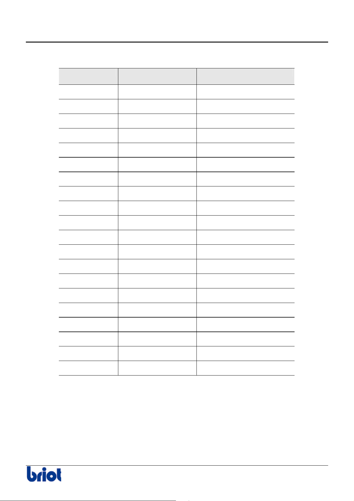
At each client visit, the Briot technician is asked to write in the following table.
Date of visit Name of the
technician
N° of the repair order
Silver FC 00 511 3
Page 9

Page 10

Installation / Starting
Page 11

Page 12
Installation / Starting
General view
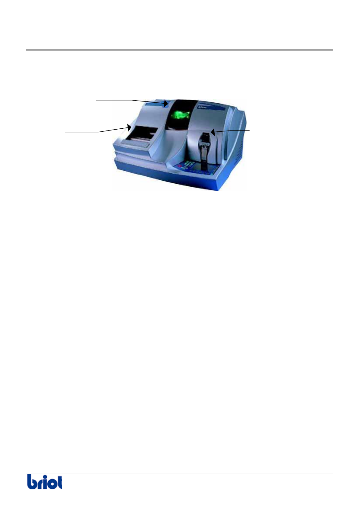
ILLUSTRATION
The following picture gives you a general view of your edger.
Scanform™ Lay-out/blocking unit
Edging unit
Installation / Starting 7
Page 13
Installation / Starting
Unpacking Machine
WARNING
If you proceed to install your edger yourself, please do not discard boxes or any of its
packing contents.
PROCEDURE
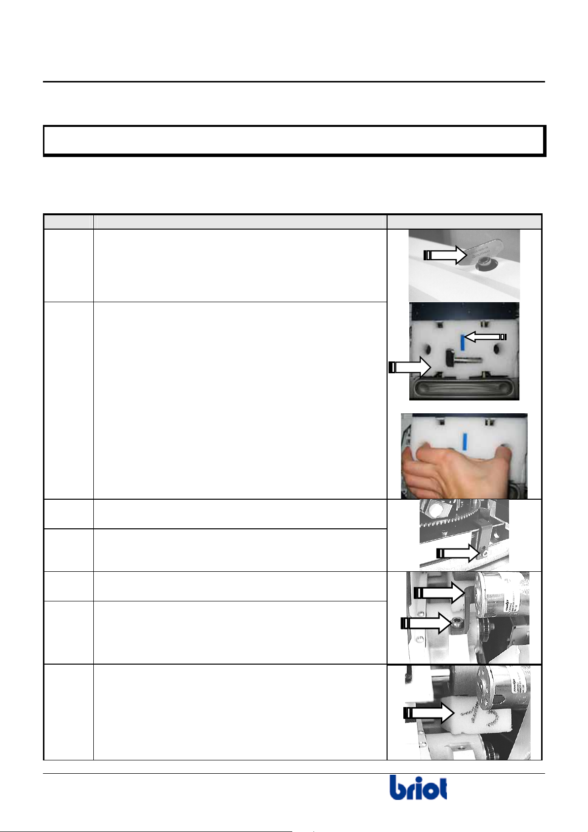
Follow the steps below to unpack your edger unit.
Step Action Illustration
1
2
Remove the edger cover guard, by using the ¼-turn key
contained in accessory box.
Carefully remove the big white wedge from the
Scanform™.
Caution!
The small blue wedge supports the stylus and is
removed when you remove the white wedge. If not, do
not forget to do it.
3
4
5
6
7
Unscrew and remove the CHC fixing screw of the red
metallic flange.
Remove the red metallic flange.
Loosen and remove the Allen screw of the carriage
shipping flange.
Remove the carriage flange.
Remove the wedge located between the chassis
and the carriage.
8
Installation / Starting
Page 14
Installation / Starting
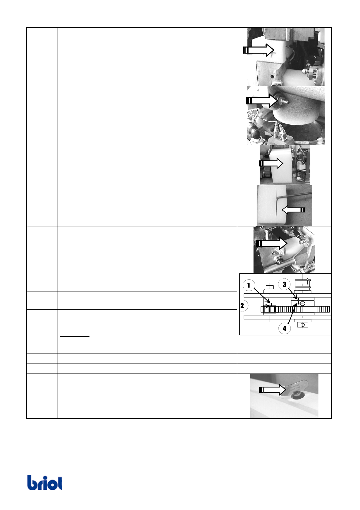
8
9
10
Remove the wedge from the top of the lifting jack.
Loosen and remove the nut and the two washers of the
threaded rod coming from the left of lifting jack.
Remove the lifting jack wedge and its rod inserted in
the translation tube.
11
12
13
14
15
16
17
Remove the wedge located between the safety-bevel
motor and the edging chamber.
Remove the cap located at the rear of the machine in
order to get access to the screw concerned.
Bring the carriage on the extreme left side (Operator
located behind the machine).
Check the set screw of the gear A is lined up with the
hole. If not, turn the gear in order to get to this situation.
Important
: before tightening the screw,
the 3&4 marks on the large gear must be lined up
(make several turns if needed).
Put a 2-mm Allen wrench into the screw.
Tighten the screw well.
Put back the edger cover guard, by using the key
contained in accessory box.
-
-
Installation / Starting 9
Page 15

Page 16

Installation / Starting
Safety Precautions
RECOMMENDATIONS
• Do not place the edger near or on top of a source of energy (radiator or heater).
• Make sure your voltage source corresponds to the voltage specified on the identification
plate, located at the rear of the machine.
• If the machine is not going to be used for a long period of time you should unplug the power
cords from the wall outlet.
Briot does not assume any responsibilities or liabilities for damages caused by
negligence or ignoring the safety precautions enlisted in this manual.
INSTALLING THE MACHINE
Installation Conditions
Before installing the machine, make sure the bench is made up of the following components:
• The bench
The bench receiving the machine must be steady and level and have a free space
of about 800 x 700 mm.
• The electricity
1 socket: 2P+T - 16 A - 220 V or 110 V protected with a differential circuit breaker
of 30 mA. It is important that the socket be well EARTHED.
• The water
¾A water intake with a stop valve equipped with a 20x27 mm male connector.
This valve must be kept for the machine and drilled at 80 cm maximum from
the place provided for the machine. It must be easily accessible and be closed
when the machine is not in use.
For a well functioning of the machine, the maximum water supply pressure must be
between 4 and 7 bar.
¾A water outlet of 80 mm diameter or greater. The drainage slope must be at least 5%
to ensure proper evacuation of the refuse.
¾For machine type Polycarbonate, provide a place under the machine with a minimum
of 600w x 510h x 460d mm to place the water container.
• The pump
Briot supplies pump systems especially made for the required water supply to Accura
and for filtering of the edging waste, with the following dimensions.
9 Width: 600 mm (24”)
9 Depth: 400 mm (16”)
9 Height: 800 mm (32”).
Silver FC 00 511 11
Page 17
Installation / Starting
Work bench preparation
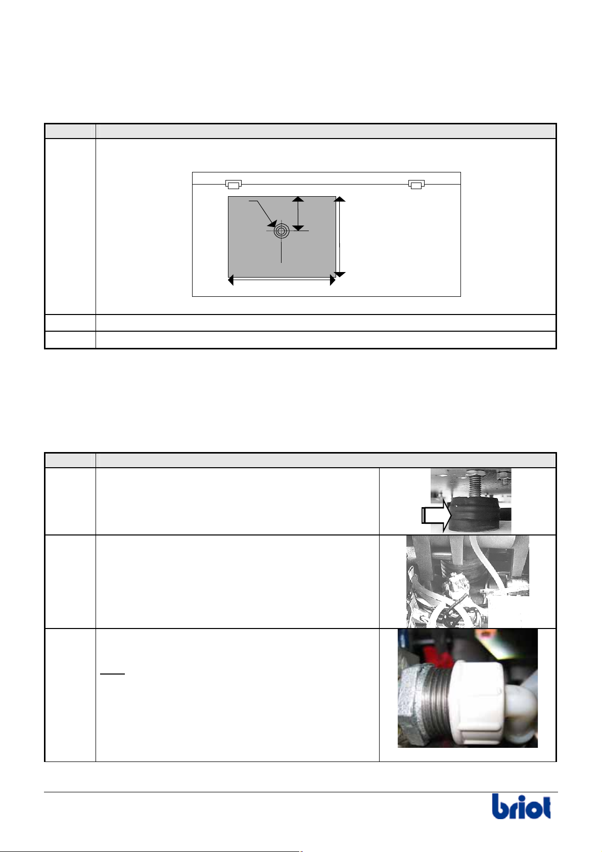
Follow the steps below to prepare the bench.
Step Action
1
Drill the bench as shown in the following diagram:
∅ 120 mm
Edger
660 mm
270 mm
305 mm
2
3
Drill the drain water hole(s).
Place the edger on the bench by positioning it in relation to the drilled holes.
Installation
Follow the steps below to install the machine.
Step Action
1
Level the machine by screwing or unscrewing
the four feet.
598 mm
Bench
2
3
Plug the drain pipe to the chassis of the machine.
Connect the water intake hose(s) to the machine
and to the faucet or the pump.
: In case of installation on direct water only,
Note
add a filter joint contained in the accessory box.
12 Silver FC 00 511
Page 18
Installation / Starting
Step Action
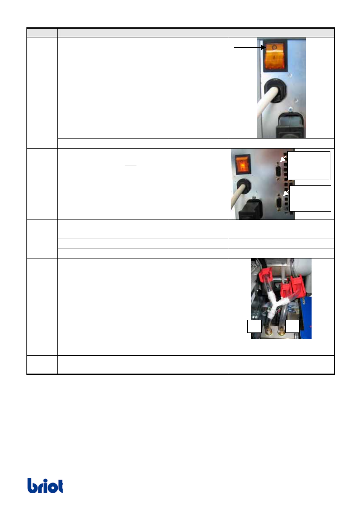
4
Check that the main switch of the machine is on
OFF position.
5
6
Connect the machine to the power outlet.
For machines configured in OMA, connect the edger
to the OMA network and
connect the barcode
reader.
Barcode
reader
connector
OMA cable
connector
7
8
9
10
11
Mount the chucks and the centering nose piece
contained in the accessory box.
Remove the cover.
Adjust the water flow by starting a cycle without lens.
Adjust each watering using the supply adjustment
wheels cf. paragraph Adjustments below.
Close the cover and make one or two jobs to check
the well functioning of the machine.
-
-
-
1 2
-
Silver FC 00 511 13
Page 19
Installation / Starting
Adjustments
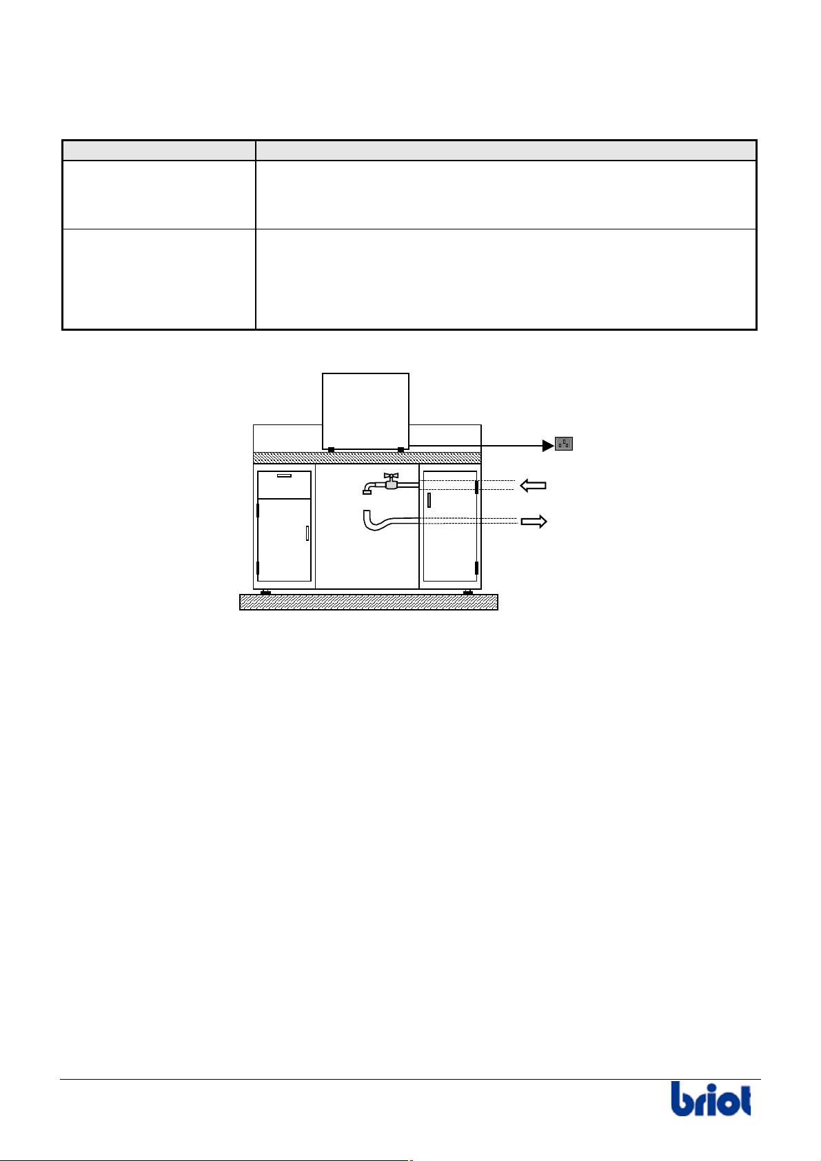
Use the water supply adjustment wheels and observe the following instructions:
Types Description
Main watering and visor
(1)
The water supply must be:
• sufficient to lubricate the edging point properly.
Accura
• sufficient to irrigate the visor evenly.
Watering at the back of
the edging unit (2)
The water supply must be sufficient to evacuate the polycarbonate
shaving that hit the base of the edging unit.
It must not be too plentiful to avoid the formation of a mist that could
moisten the TP rough edging wheel and create an undesirable
“ribbon” edging of the polycarbonate.
Installation on Workbench
14 Silver FC 00 511
Page 20

Use
Page 21

Page 22
Use : Introduction to your machine
Introduction to the machine
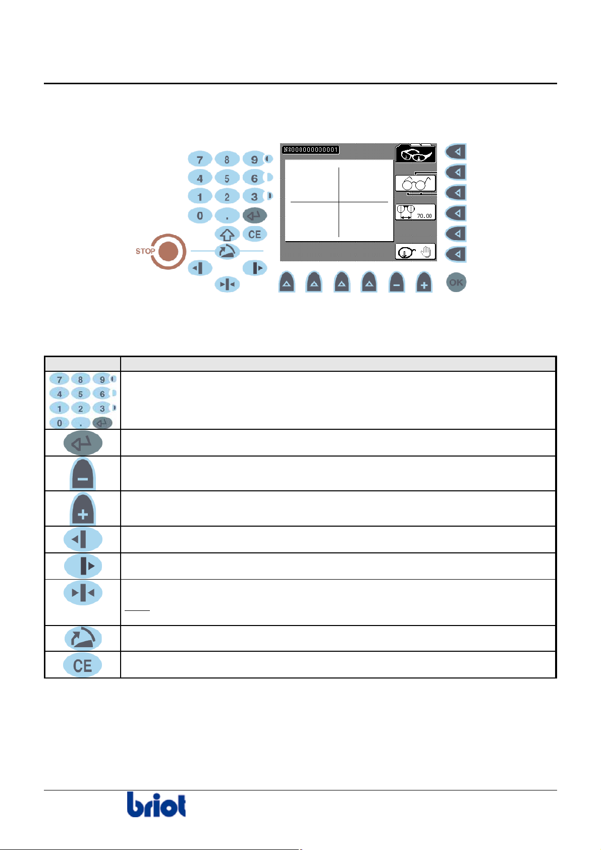
KEYPAD/SCREEN INTERFACE
Keys: Diagram
Keys: Description
The following table describes each key of the keypad.
Key Function/description
Enter numerical values.
Confirm the entered numerical value.
Decrement the selected numerical value.
Increment the selected numerical value.
Move the lens left during roughing and/or rimless.
Move the lens left during roughing and/or rimless.
Tighten/loosen the lens clamp.
Note
: This key exists also to the left of the edging station, for left-handed
people.
Maintenance function. Refer to Annex A, paragraph Emptying the main tank.
Correct error while in entry process.
Silver FC 00 511
17
Page 23
Key Function/description
Make it possible, in combination with the following key:
to consult the statistics with regard to:
9 the lens counters
9 the wheel dressing
9 the lens feeler calibration
to access the screens with regard to the adjustment of:
9 the temperature compensation
9 the operator’s language
9 the memory management
9 the size correction
to increase the screen brightness
to access the screens with regard to:
9 the wheel dressing
9 the size adjustment
with an accuracy of 1/100th mm)
(use a digital caliper rule
9 the replacement of the lens feeler tip
9 the adjustment of the Scanform™
9 to access the lens feeler calibration screen
to decrease the screen brightness.
to reverse the screen color.
to enter a positive numerical value
to enter a negative numerical value
Validate a function.
Make it possible to carry out an emergency stop for edging.
Unmarked key (Fct0 to Fct5), its meaning depends of the parameter displayed
to the left of this key.
Unmarked key (Fct6 to Fct9), its meaning depends of the parameter displayed
facing this key.
Initial Display
When turned on, the edger initializes automatically and displays the following screen.
18 Silver FC 00 511
Page 24
Use : Introduction to your machine
SCANFORM™ UNIT
Description
The Scanform™ integrated on the left of the machine is composed of the following units:
• frame positioning station;
• jaw-opening plate.
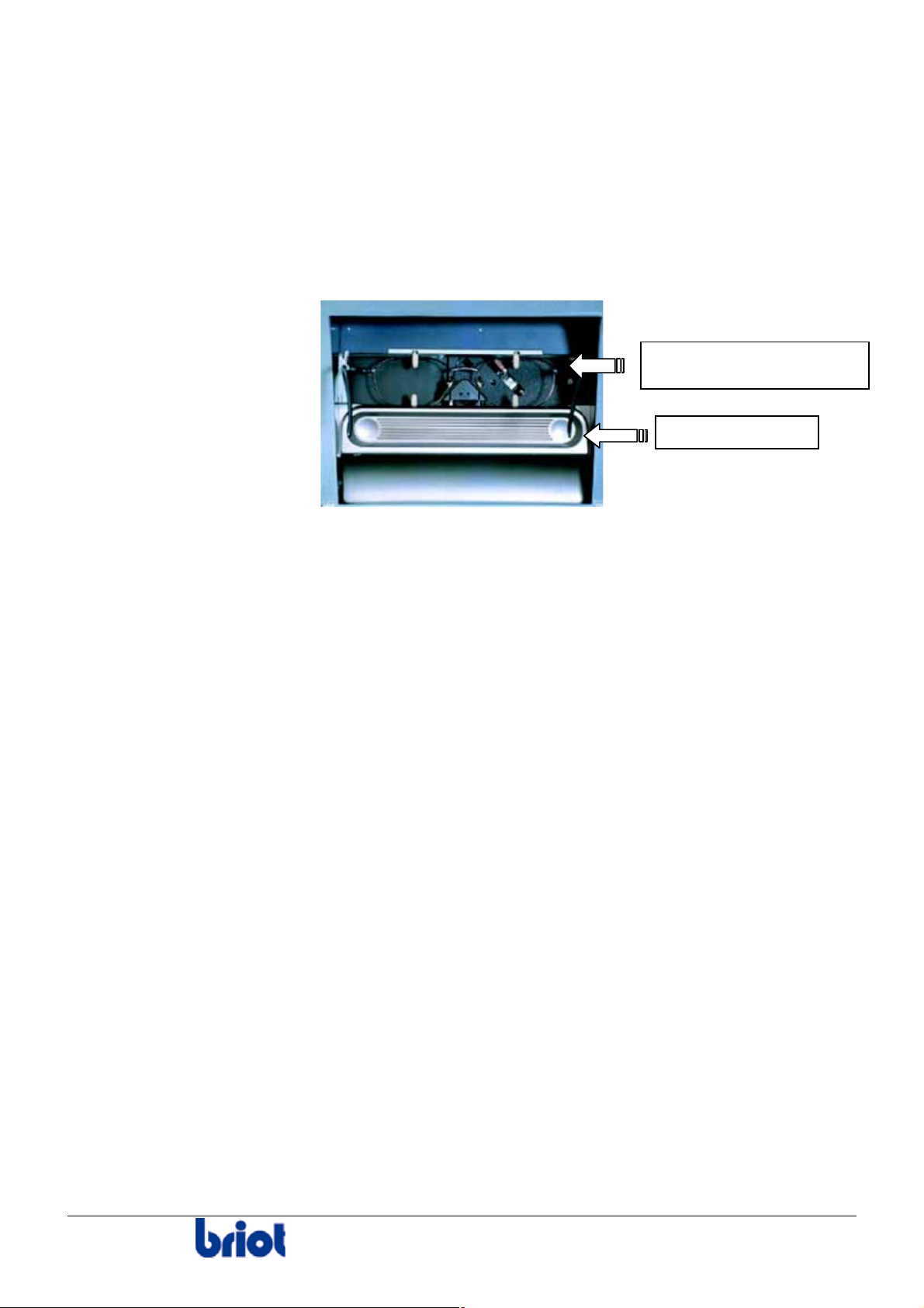
Illustration
Frame positioning station
Jaw-opening plate
Silver FC 00 511
19
Page 25
Basic concepts
BASIC CONCEPTS
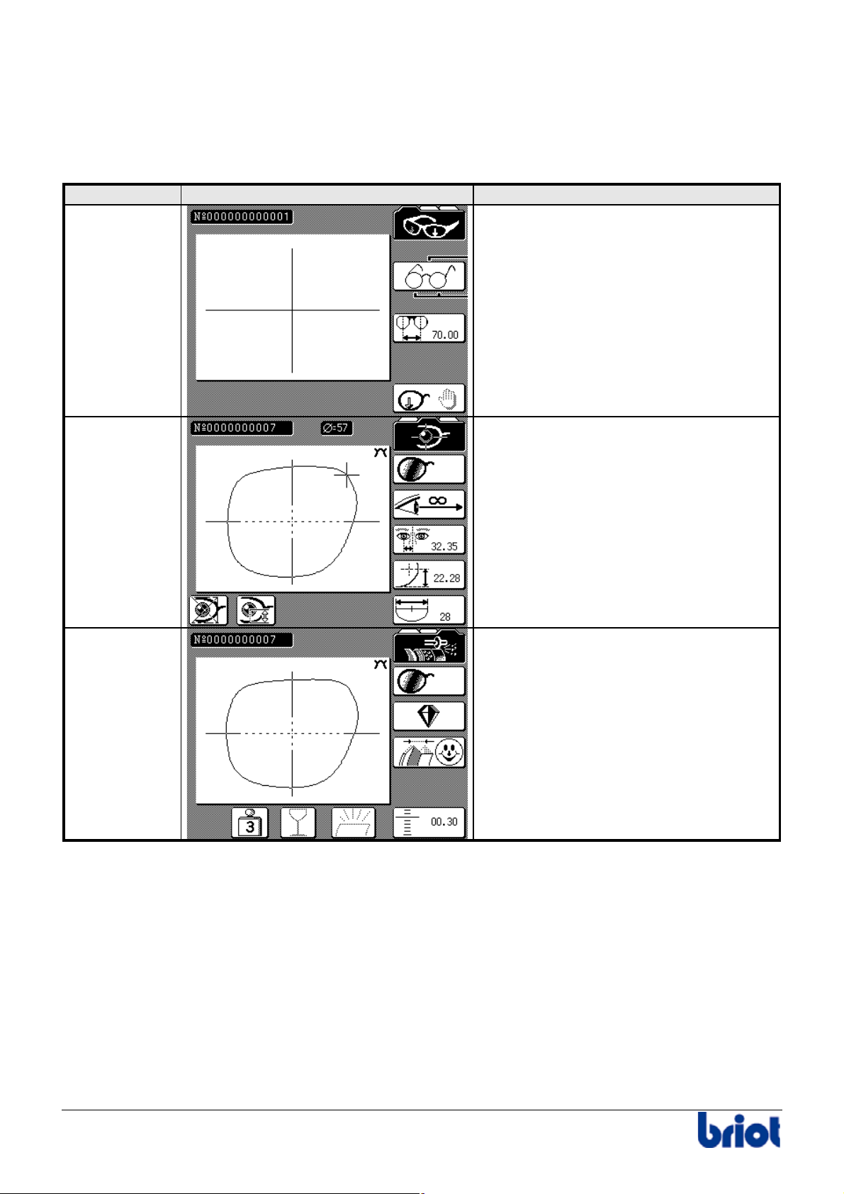
Three Working Modes
The edger makes three basic operations corresponding to a screen called "mode" that you can
identify by a symbol located on right side of the screen.
Mode Screen Functions
Tracing Allow you to enter the following
parameters:
• job number
• frame type
• frame side to be traced
• frame PD or Bridge
• tracing type
• job destination
• job origin
Lens Layout/
Blocking
Allow you to enter the following
parameters:
• lens to be laid out
• vision type
• horizontal decentration
• height decentration
• segment width for near vision
• lay-out/blocking mode
• type of decentration
Edging Allow you to enter the following
parameters:
• lens to be edged
• lens type
• lens finishing type
• bevel type
• lens final size
• edging pressure
• polishing
20 FC 00 511
Page 26
Basic concepts
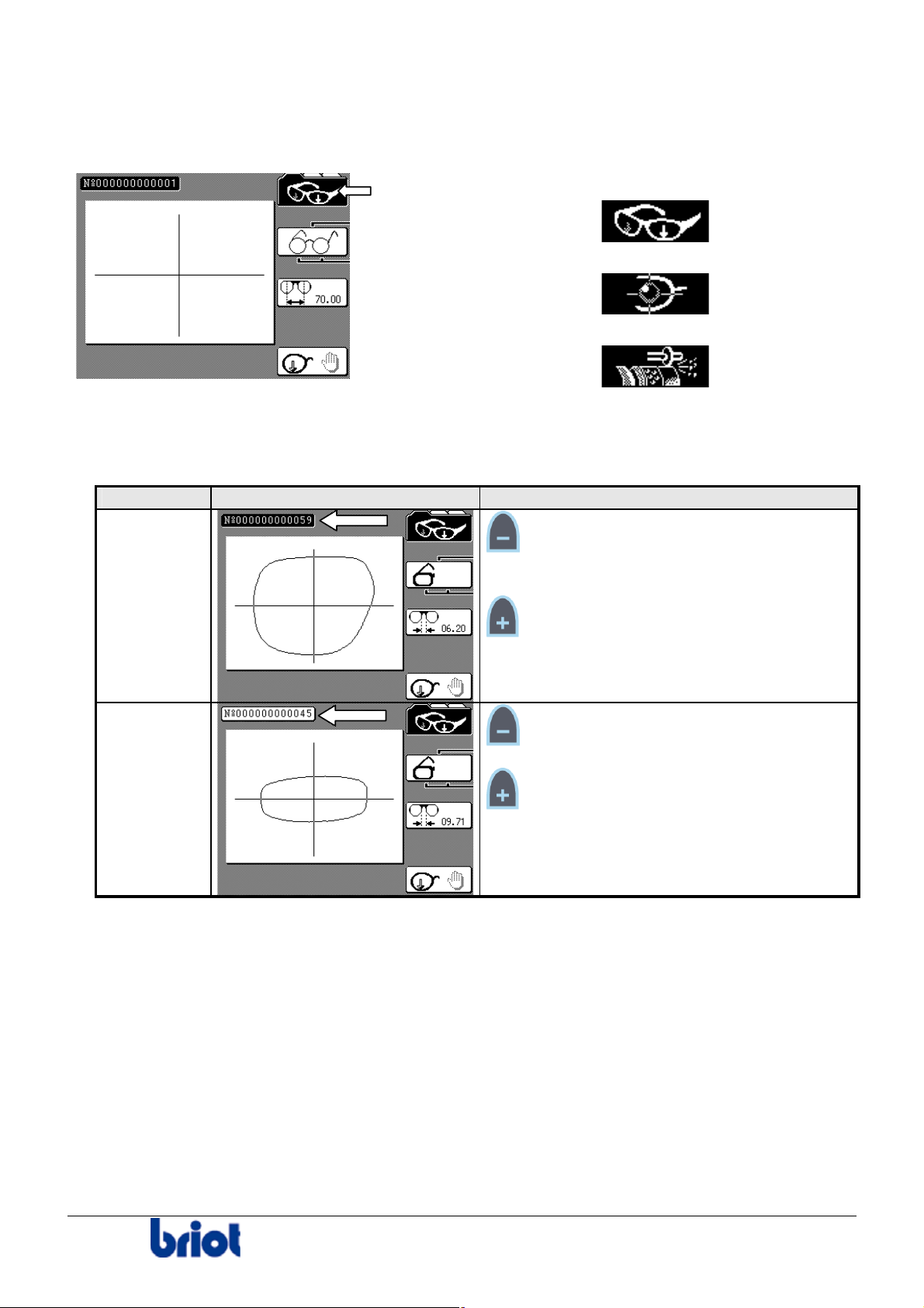
Going from One Mode to the Other
To switch from one mode to the other, press on the function key Fct 1 and display the desired
screen.
The screens scroll in the following order:
1. Tracing screen:
2. Lay-out screen:
3. Edging screen:
Current Job/Previous Job
The memory buffer can contain two jobs (First In- First Out), managed as follows.
Job Illustration Managing
current job:
job number
in inverse
video
previous
job: job
number
in normal
video
Key:
• access to the previous job, in the three
modes.
Key:
• creation of a new job and deletion of the
previous job, in tracing mode.
• inactive, in lay-out and edging modes.
Key:
• inactive, in the three modes.
Key:
• access to the current job, in the three
modes.
Your machine is equipped as standard with a memory board able to contain 156 jobs (117 + 39).
You can work either:
• with the memory buffer (by default);
or
• with the memory extension board;
or
• with an external server.
These three configuration modes are exclusive: you work in one mode OR the other.
See Annex B to use your edger with the memory extension board and Annex C to use it
connected to an OMA server.
FC 00 511
21
Page 27

Page 28
Use : Precautions for use
Precautions for use
RECOMMENDATIONS
Installation and starting
• Do not place the edger near or on top of a source of energy (radiator or heater).
• Make sure your voltage source corresponds to the voltage specified on the identification
plate, locatedat the rear of the machine.
• If the machine is not going to be used for a long period of time you should unplug the power
cords from the wall outlet.
Performance of a job
1. Clean the frames in the ultrasonic cleaner before tracing.
2. Use new adhesives.
3. Change the blocks regularly. Their lifespan is 100 blocking operations.
4. Close the visor regularly to ensure it is automatically rinsed (this starts automatically when the
visor is closed for more than 5 minutes).
CAUTION
Do not use any type of spray hose to clean your system. Avoid any heavy splashing or
spraying that may penetrate the system's scanning and keyboard/interface. This can
cause electrical damage to the system.
Never use chemical solvents, agents or derivatives of such products as:
Acetone
Trichlorethylene
Benzene
Kerozene
Lighter Fluid or
any product bearing the notice "Do not use on plastic or painted surfaces".
any product with a CHLORINE, AMMONIA or SODA base.
These products directly or even by their simple vapors:
risks altering the structure of synthetic materials used.
Usage of any of these materials WILL VOID ANY GUARANTEE OR WARRANTY OF THE
WHOLE UNIT OR ITS COMPONENTS.
Never manipulate the lens feeler pliers located in the edging station.
THE MANUFACTURER CANNOT BE HELD RESPONSIBLE FOR ANY DAMAGE CAUSED
BY THE USE OF THE EDGER IF THE SAFETY REGULATIONS AND THE PRECAUTIONS
FOR USE ARE NOT OBSERVED.
Silver FC 00 511 23
Page 29
Use: Standard use
Standard use
CREATING A JOB
Tracing Mode
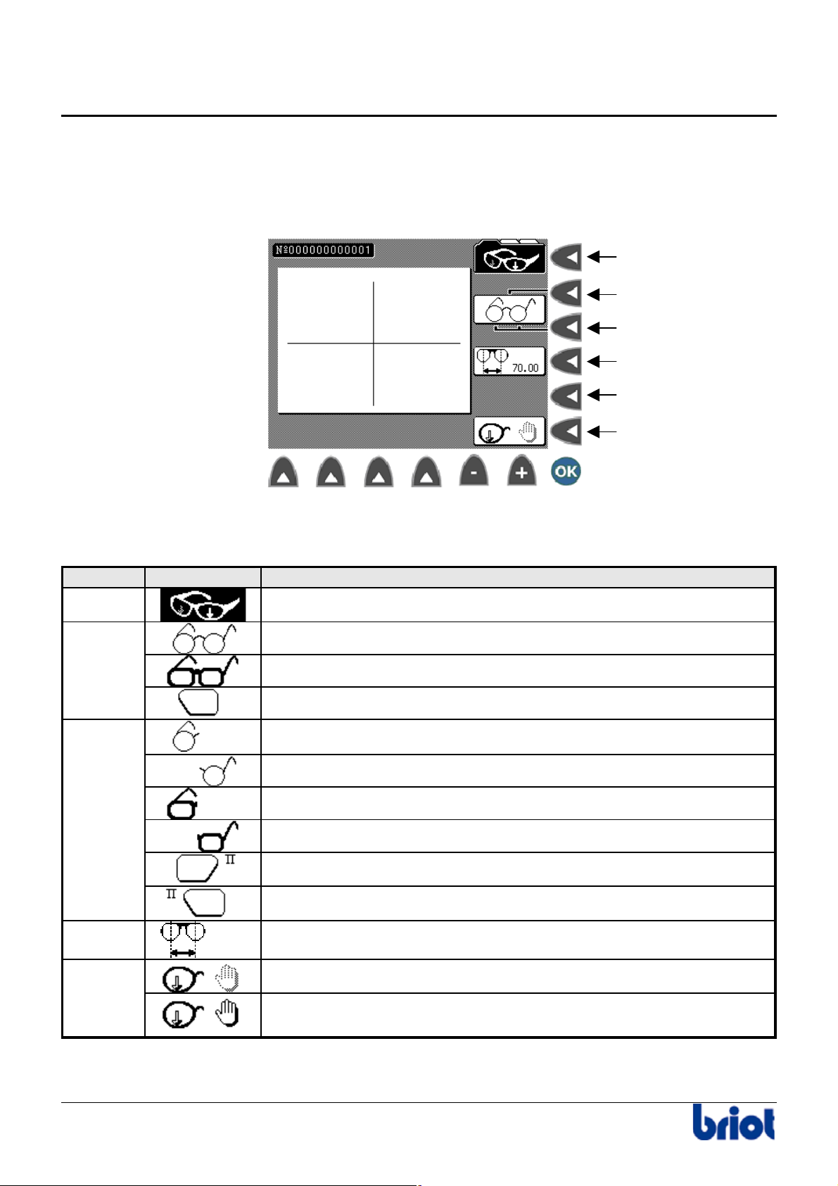
Functions : illustration
Fct 0
Fct 1
Fct 2
Fct 3
Fct 4
Fct 5
Functions : description
The following table describes each function with regard to the tracing screen of the Silver.
Function Selection Description
Fct0
Fct1
Fct2
Tracing Mode
Metallic frame
Plastic frame
Pattern or demonstration lens tracing
Tracing the right side of a metallic frame
Tracing the left side of a metallic frame
Tracing the right side of a plastic frame
Tracing the left side of a plastic frame
Tracing the right side of a pattern
Tracing the left side of a pattern
Fct3
+70.40
Fct5
Distance between centers (DBC)
Automatic tracing
Manual tracing: placing the stylus tip into the groove manually – slow
tracing
24 Silver FC 00 511
Page 30
Use: Standard use
Tracing a frame shape
Procedure
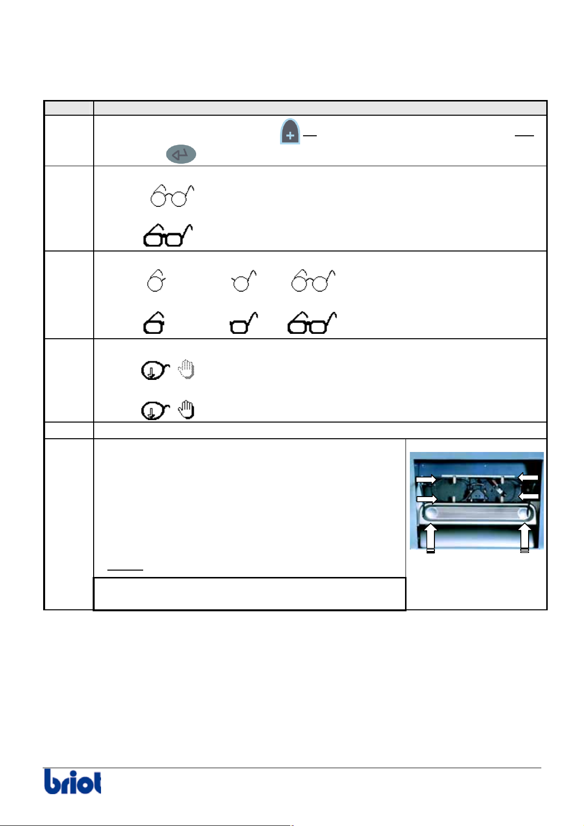
Follow the steps below to trace a frame shape.
Step Action
1
Create a job number: press the key
or enter the job number using the keypad and
2
3
4
5
6
press the key
.
Select the type of frame using Fct1 :
•
Or
•
.
Select the side(s) to be traced using Fct2 :
•
, , or
Or
•
, , or
Select the tracing type using Fct5 :
•
Or
•
Before tracing, clean the frame in the ultrasonic cleaner.
Insert the frame into the Scanform™ as follows:
• bring the jaw-opening plate towards you and keep
the jaws in the open position;
• place the top of the frame in the upper clips of the
Scanform™;
• push back the plate and let it go off making sure
that the bottom of the frame is placed between the
lower clips;
Result:
the frame is held.
Make sure that the joints of the eye wires to be traced are
properly closed.
Silver FC 00 511 25
Page 31
Use: Standard use
Step Action
7
Press the key
to start the tracing
cycle.
Result: the frame tracing is performed.
Tracing a pattern or a demonstration lens shape
Procedure
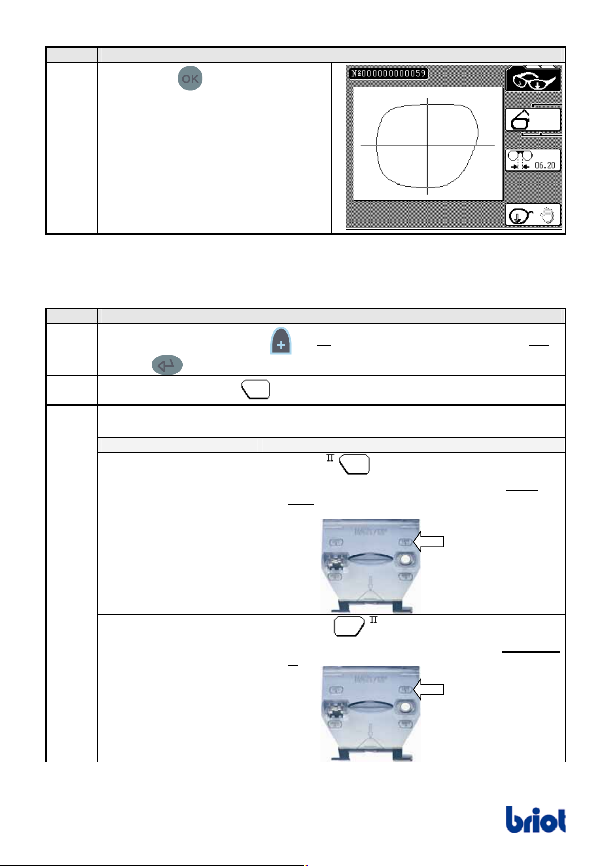
Follow the steps below to trace a pattern or a demonstration lens shape.
Step Action
1
Create a job number: press the
key or enter a job number using the keypad and
2
3
press the
key.
Select the type of frame
Select the side to be traced using Fct2.
To do this, proceed as follows.
If you trace the… then…
left side
right side
, using Fct1.
1. Select
.
2. Insert the pattern placing the nose part to the
right or insert the right-hand demonstration lens.
Support
Pattern
gabarit
holder
1. Select
.
2. Insert the pattern placing the nose part to the left
or
insert the left-hand demonstration lens.
Support
Pattern
gabarit
holder
26 Silver FC 00 511
Page 32
Use: Standard use
Step Action
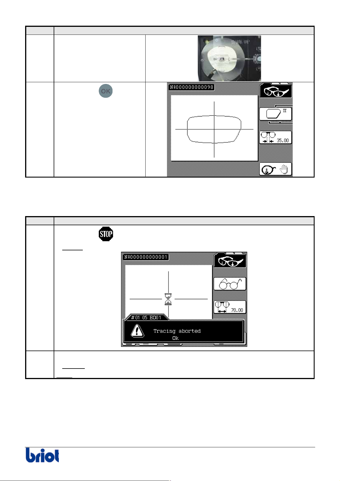
4
Put the pattern holder with a
pattern to be traced on the
frame holder.
5
Press the key
to start
the tracing cycle.
Stopping the tracing process
In case of problems, you can stop the shape tracing cycle at any time.
To do this, proceed as follows.
Step Action
1
Press the key
which is displayed on the bottom left of the screen.
the tracing is stopped and the following message is displayed:
the message disappears from the screen.
you can resume the tracing again. To do this, see the previous procedure.
2
Result:
Press the function key Fct8.
Result:
Note:
Silver FC 00 511 27
Page 33
Use : Standard use
LAYING OUT AND BLOCKING A LENS
Lay-out/Blocking Mode
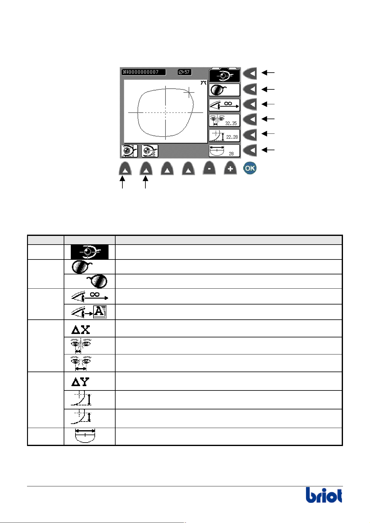
Functions : illustration
Functions: description
The following table describes each function of the Silver lay-out/blocking screen.
Function Selection Description
Fct0
Fct1
Fct2
Fct3
+06.00
+30.00
+62.00
Fct4
+05.00
+28.00
+25.00
Fct5
Fct 6 Fct 7
Lay-out/Blocking Mode
Lay-out/Blocking of the right side
Lay-out/Blocking of the left side
Distance vision
Near Vision (for multifocals)
Horizontal movement from the boxing center in millimeters
Monocular Pupil Distance
Binocular Pupil Distance
Vertical movement from the boxing center in millimeters: A vertical
decentration height from the boxing center
BOX height: From the pupil center to the lowest vertical point of the
lens, at the bottom of the frame.
MIX height: From the pupil center to the first vertical point located on
the edge and in the lower part of the lens.
28
Segment width
Fct 0
Fct 1
Fct 2
Fct 3
Fct 4
Fct 5
28 Silver FC 00 511
Page 34
Use : Standard use
Function Selection Description
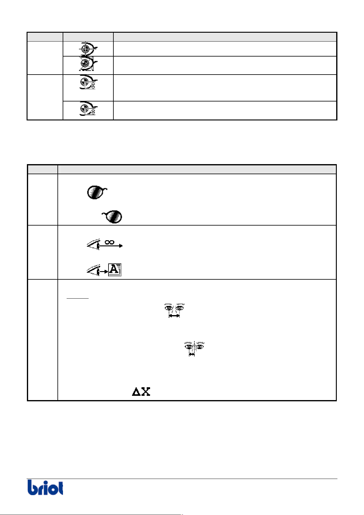
Fct6
Optical center: the lens is laid out and blocked on the optical center.
Geometric centre: the optical centre is moved from the mechanical
Fct7
centre
BOX decentration:
Height calculated from the optical center to the extreme bottom point
of the frame
MIX decentration: Height calculated from the optical center to the
base of the frame on the nasal side
Laying out and blocking the lens
Procedure
Follow the steps below to lay-out and block the lens.
Step Action
1
Select the lens to be laid out using Fct1:
2
3
•
Or
•
.
Select the type of vision using Fct2 (refer to the paragraph Layout examples below):
•
Or
•
.
Enter the client’s binocular pupil distance using Fct3.
Result:
the machine automatically interprets the entered value as being:
• a total pupillary distance
+62.00
Or
• a monocular pupillary distance
+30.00
Or
• a decentration
Silver FC 00 511 29
+06.00
.
Page 35
Use : Standard use
Step Action
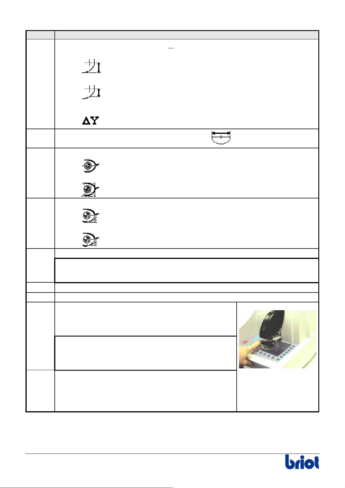
4
Enter the height of the optical center or
the bifocal using Fct4.
5
6
7
•
+28.00
Or
•
+25.00
Or
•
+05.00
.
If necessary, enter the segment width of the bifocal
If necessary, select the lay-out mode using Fct6.
•
Or
•
.
If necessary, enter the height type using Fct7 :
•
Or
28
using Fct5.
8
•
Place a double-sided adhesive tape on a block.
.
The blocks have a use limit of 100 blocking operations.
Any use beyond this limit could lead to axis or pupillary distance problems for which
Briot declines all responsibility.
9
10
11
Place the block inside the blocker of the machine.
Remove the protection from the tape.
Place and center the lens to be blocked on the screen
according to the desired layout method (See Comment
& Layout Examples paragraph below).
In case of thin or high cylinder lenses, place the lens
holder ring contained in accessory box between the screen
and the lens to hold and avoid it to break or move.
12
Operate the blocker arm by pushing on the two tabs
designed for this.
Caution! Hold the blocker arm as it returns to make sure
it does not hit the body of the machine.
30 Silver FC 00 511
Page 36
Use : Standard use
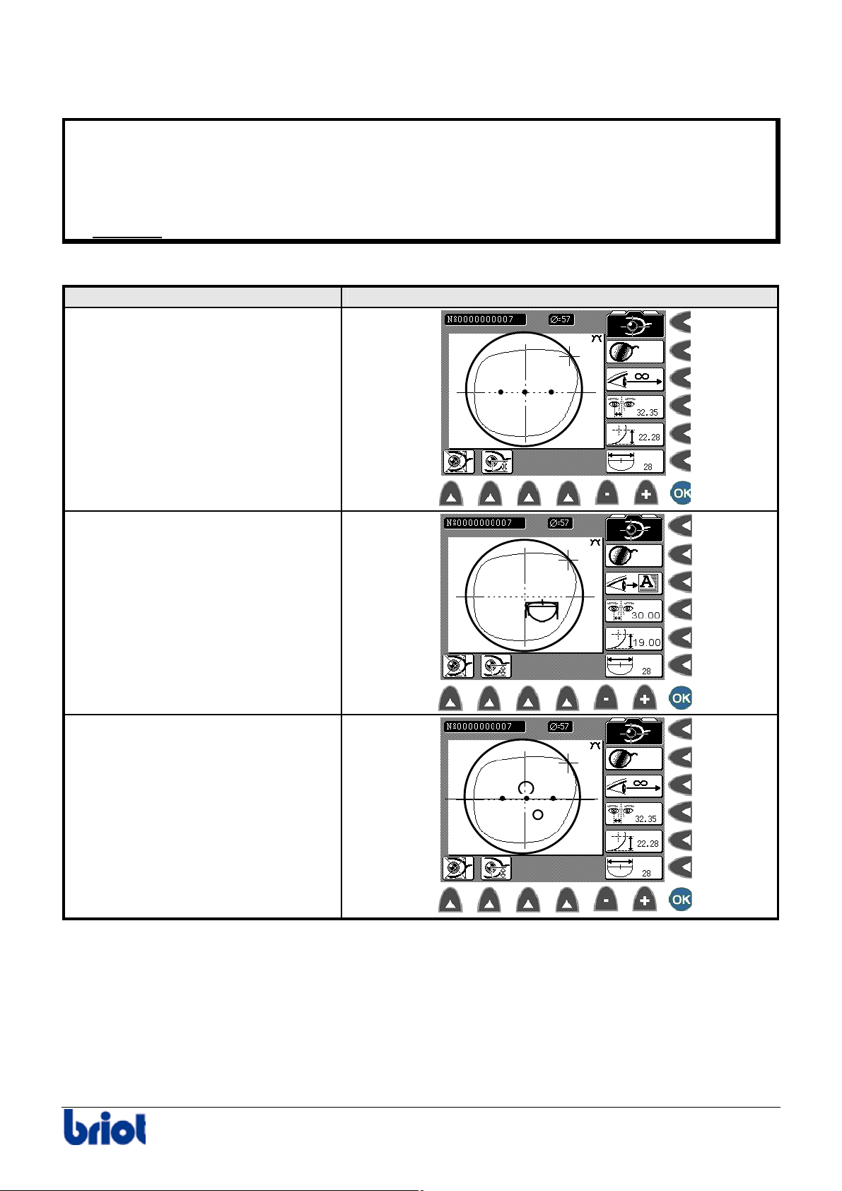
Comments & Lay-out examples
In case of doubt regarding the lens size for cut out, you can:
• Visually inspect the lens shape on the screen, under the lens blank to verify the lens blank
is large enough.
• Compare the lens blank side diameter to the diameter value displayed at the top of the
screen.
Example:
Lens Layout/Blocking Illustration
Single Vision
Ø45
Bifocal
Progressive
Silver FC 00 511 31
Page 37
Use : Standard use
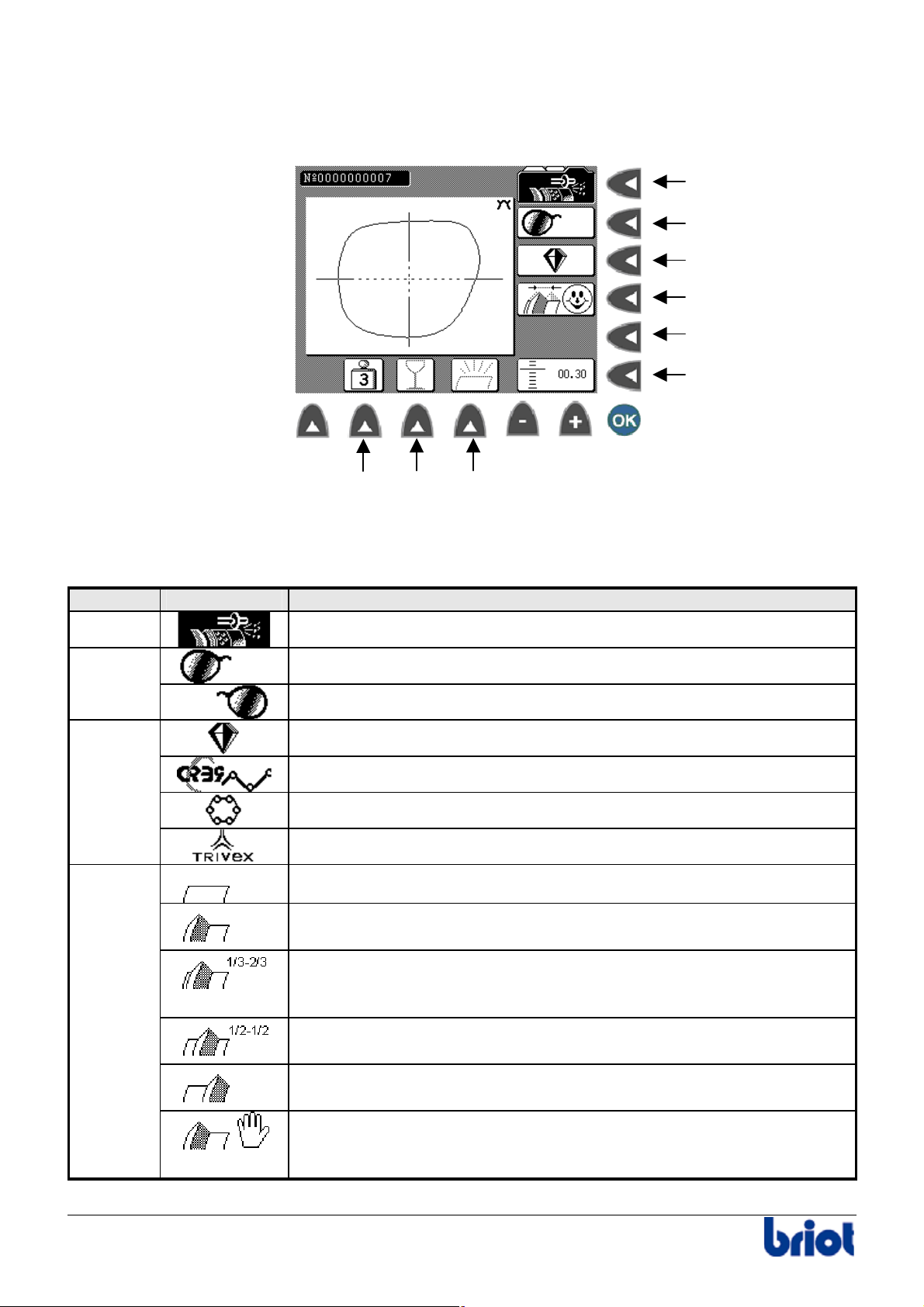
EDGING A LENS
Edging Mode
Functions : illustration
Fct 0
Fct 1
Fct 2
Fct 3
Fct 4
Fct 5
Fct 7 Fct 8 Fct 9
Functions : description
The following table describes each function with regard to the edging screen of the Silver.
Function Selection Description
Fct0
Fct1
Fct2
Fct3
Edging Mode
Edging the right side
Edging the left side
Glass lens
Organic lens
Polycarbonate lens
Trivex lens (depends on the type of edging wheel mounted)
Rimless Finishing
Front Side Bevel:
The bevel is placed to the front of the lens.
1/3-2/3 Bevel:
The bevel is placed at 1/3 from the front face and at 2/3 from the rear
face of the lens.
½ – ½ Bevel:
The bevel is placed in the center of the lens.
Rear Side Bevel:
The bevel is placed to the rear side of the lens.
Controlled bevel:
the bevel is positioned by the operator (see paragraph Controlling
the bevel of the lens before finishing below)
32 Silver FC 00 511
Page 38
Use : Standard use
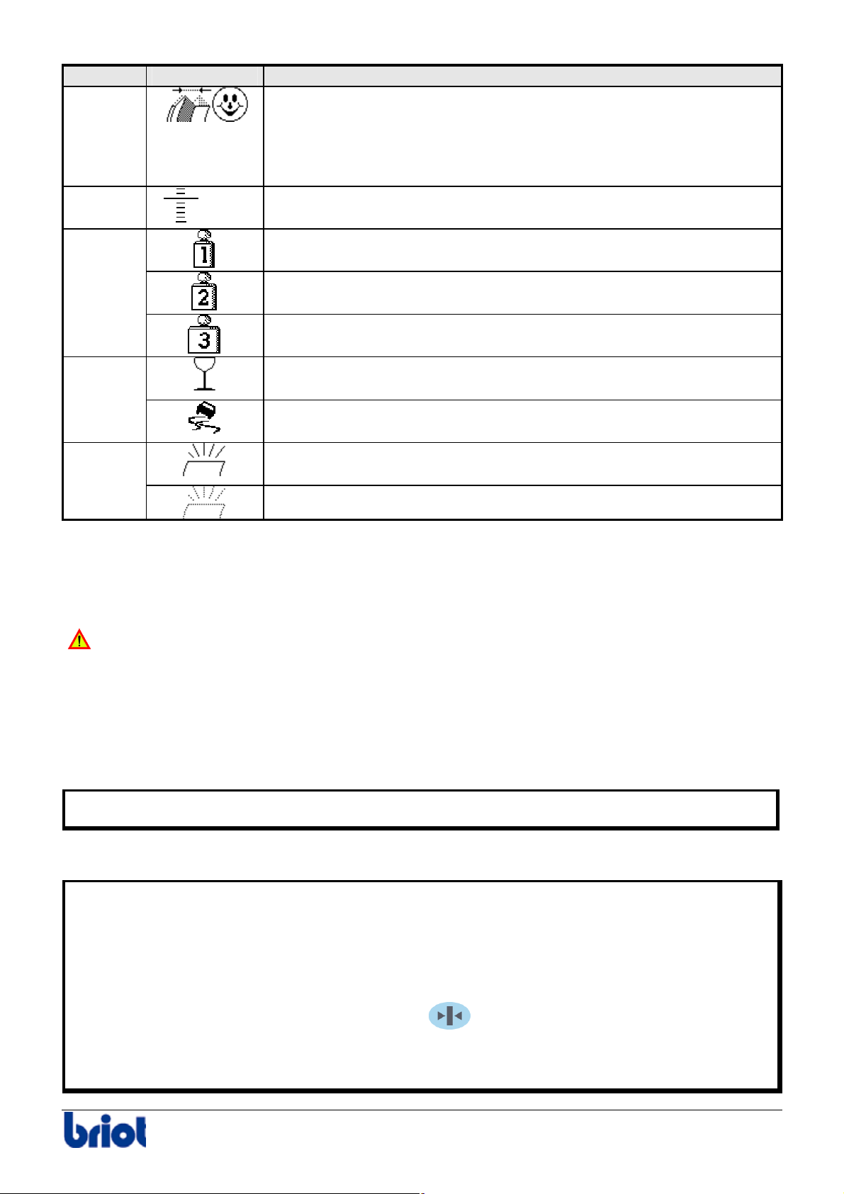
Function Selection Description
Automatic bevel; based on a 1/3 – 2/3 bevel, the bevel is placed as
close as possible to the front surface of the lens. The lens size is
adapted to the curvature of the frame for the best possible fit. The
circumference of the lens is the same as the circumference of the
frame.
Fct5
Fct7
+00.00
Retouch:
final lens size
Minimum Edging Pressure:
to edge a thin lens
Medium Edging Pressure:
to edge a medium lens
Maximum Edging Pressure:
to edge a thick lens
Fct8
Edging cycle for fragile lenses:
to edge a very thin lens
Water repellent lenses: special program to edge water repellent
Fct9
lenses.
Lens Polishing:
only for organic lenses
No polishing of the lens
Edging a Lens
Important notes
o Mind the adapters!
Risk of collision of the adapter with the wheels.
Mind the lens clamping adapters for each type of job you are working on.
Two types of “small” adapters are used on the machines: Ø19 mm and Ø17 mm – flat.
The use of the 19mm adapters when the 17mm – flat ones are required will cause a collision of the
adapters with the wheels!
• Use the 19mm adapter when the message “Small adapter mounted?” is displayed.
• Use the 17mm adapter when the message “Small flat adapter mounted?” is displayed.
Do not open visor while edging, or put your hands inside the edging unit.
If you want to open the visor, refer to paragraph Visor safety below.
o Clamping safety
The following controls make it possible to ensure optimal operator safety.
Rotation of the edging wheels:
• The main motor will not start until the visor is closed.
• Manual opening of the visor stops the wheel motor. The clamping shafts open half-way.
Clamping:
• To clamp the lens you have to hold the key
the lens.
• If you release this key during closing of the lens clamp shaft, the clamping system opens
automatically.
until the clamping shaft is in contact with
Silver FC 00 511 33
Page 39
Use : Standard use
• You have two seconds to release the key when the clamp is in contact with the lens
otherwise the clamp opens back if this delay is over.
• If you start a cycle with the clamping system open, the warning message “Clamp the lens
first ” is displayed.
o Visor safety
• For safety reasons, the shafts open only if the visor is open.
• If you want to open the visor during edging press the key
. Watering of the
machine visor stops immediately, the edging wheels no longer turn and the edging of the lens
is interrupted.
o Interruption of the edging cycle
The edging cycle can be interrupted at any time.
To do this, press the
Result:
the edging cycle stops immediately and the clamping shafts open half-way.
key.
Procedure
Follow the steps below to edge a lens.
Step Action
1
2
3
4
5
6
Call or create a job (refer to the sections Tracing or Calling a job).
Result:
the shape appears on the screen with its edging parameters.
Block and lay out the lens.
To place the lens in the edger proceed as follows:
1. Open
2. Press the
the visor manually.
key on the keyboard to open the lens clamp.
3. Place the blocked lens into the left side adaptor.
4. Press the
key on the keypad and hold it down until the clamping shaft is in
contact with the lens.
Check that the water supply to the machine is correct.
Select the side to edge, using the key Fct1 (see paragraph Functions: description
above).
Check the following edging parameters and re-select them if needed
• type of lens (Fct 2);
• type of finishing (Fct 3) ;
• type of sub-finishing (Fct 4);
• type of counter-weight (Fct 7 and 8);
• polishing option (Fct 9).
34 Silver FC 00 511
Page 40
Use : Standard use
Π
Π
Step Action
7
the visor manually and start the edging cycle using the key.
Close
Result:
The visor closes automatically and the edging cycle starts in the following
order:
1. Roughing
2. Tracing
3. Result: If the lens is too small for the shape, a message appears on the screen.
Go to paragraph Re-tracing a lens below.
4. Finishing
5. Polishing (if selected)
When edging is finished, you may open the visor manually.
8
Result:
To open the lens clamp, hold the lens whilst pressing the key on the keypad
(or the key situated on the left of the edging unit for left-handers).
9
Remove the lens from the left side adaptor, making sure not to remove the block
as some re-edging might be necessary for proper sizing of lens.
Re-feeling a lens
Caution! You can re-feel a lens only when you are at the bevel finish step.
Follow the steps below to re-feel a lens.
Step Action
1
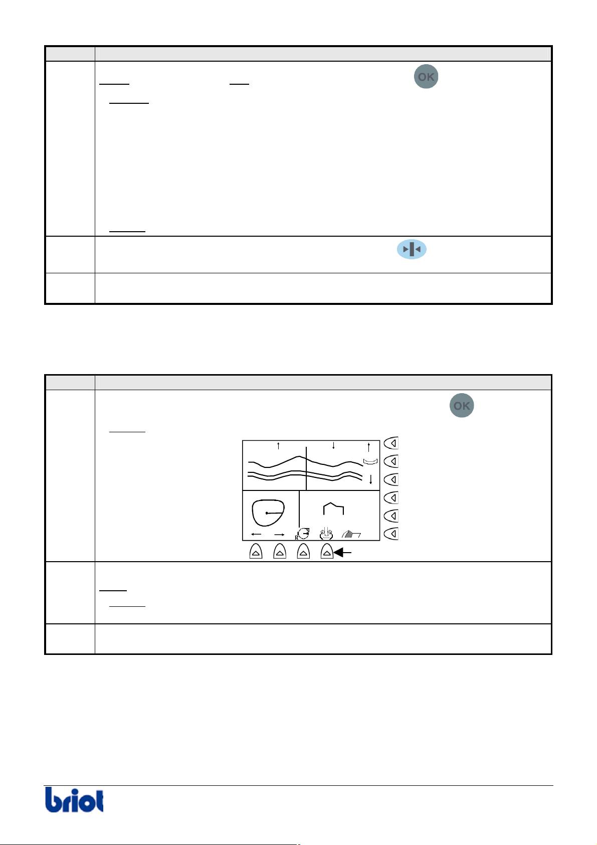
When the message Lens too small for shape is displayed, press the
key.
the following screen is displayed.
1.48 2.97
4.45
1/3-2/3
Fct9
you can re-feel the lens up to three times from 0.5 mm inside each time.
If these three operations are not sufficient, the lens is much too small, the
2
Result:
Press the Fct9 key to re-feel the lens from 0.5 mm inside the lens.
Note:
Result:
machine cannot edge it.
3
Perform the finishing cycle. To do this, go to step 7 – phase 3 of the procedure Edging
a lens above.
Silver FC 00 511 35
Page 41
Use : Standard use
Π
Π
→
←
Beveling a lens
Selecting the bevel finish
If you … Then …
have not selected the function
finishing is performed automatically after the
roughing and the lens feeling.
Go to step 8 of the edging procedure
described above.
have selected the function
the finishing will be in accordance with the
parameters you entered previously.
Go to the procedure Controlling lens bevel
before finishing below.
Controlling the bevel before finishing
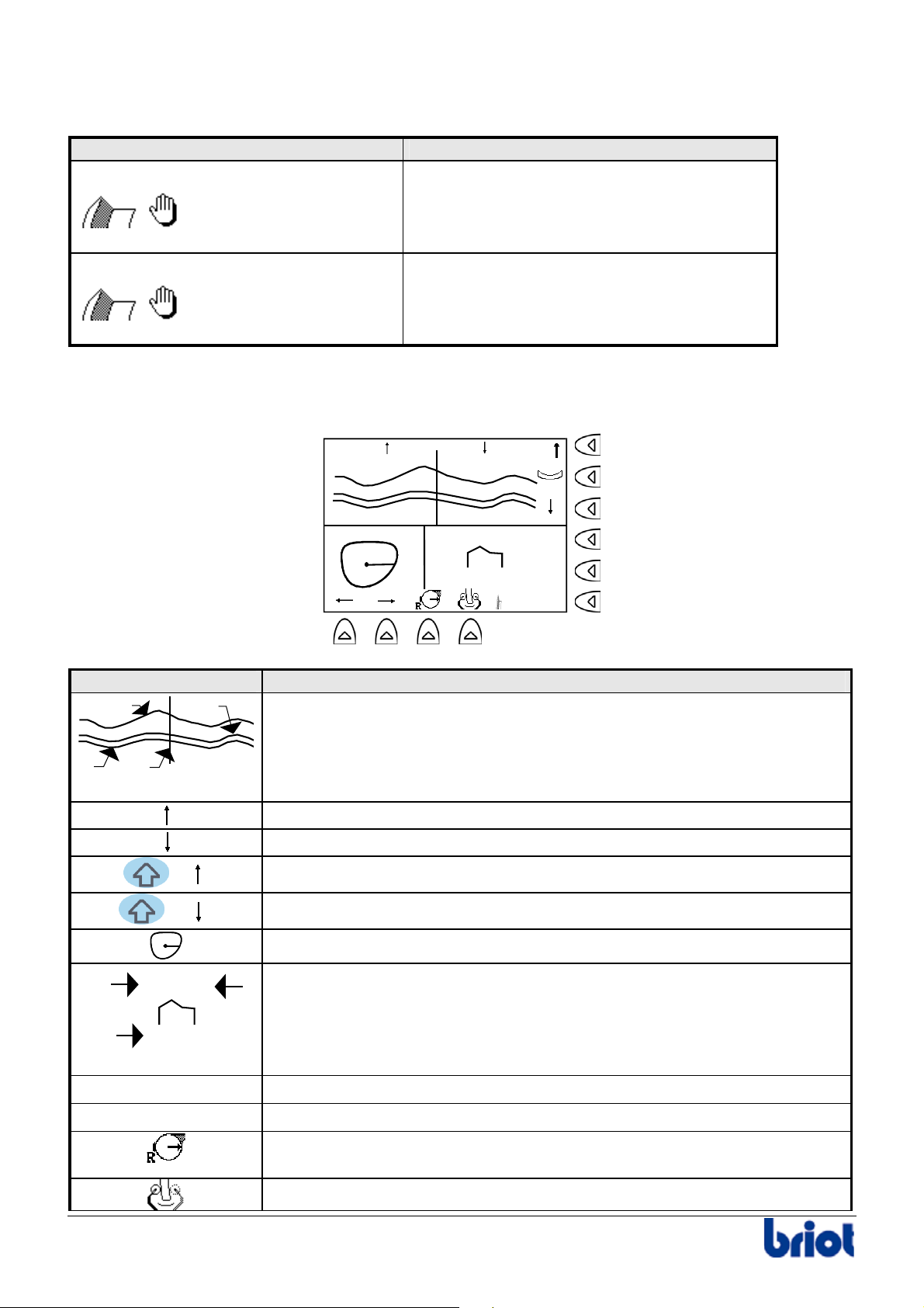
o Display description
1.48 2.97
4.45
1/3-2/3
Symbol Description
1
2
Developed curve of the lens’s edge and of the bevel:
1. Rear side of the lens
2. Bevel apex
3
4
3. Front side of the lens
4. Position Index
+
+
1
1.48 2.97
Move the bevel apex towards the back of the lens.
Move the bevel apex towards the front of the lens.
Allow the bevel to pivot towards the rear of the current index position.
Allow the bevel to pivot towards the front of the current index position.
Position Index
Lens profile corresponding to the current index:
2
1. Top bevel Position/front side
3
4.45
2. Top bevel Position/rear side
3. Value of the lens thickness
Allow the lens index to be moved to the right.
Allow the lens index to be moved to the left.
Make it possible to select the bevel point the position of which will be
changed (the opposite point is the pivot which cannot move).
Allow the lens to be re-felt.
36 Silver FC 00 511
Page 42
Use : Standard use
Π
Π
Symbol Description
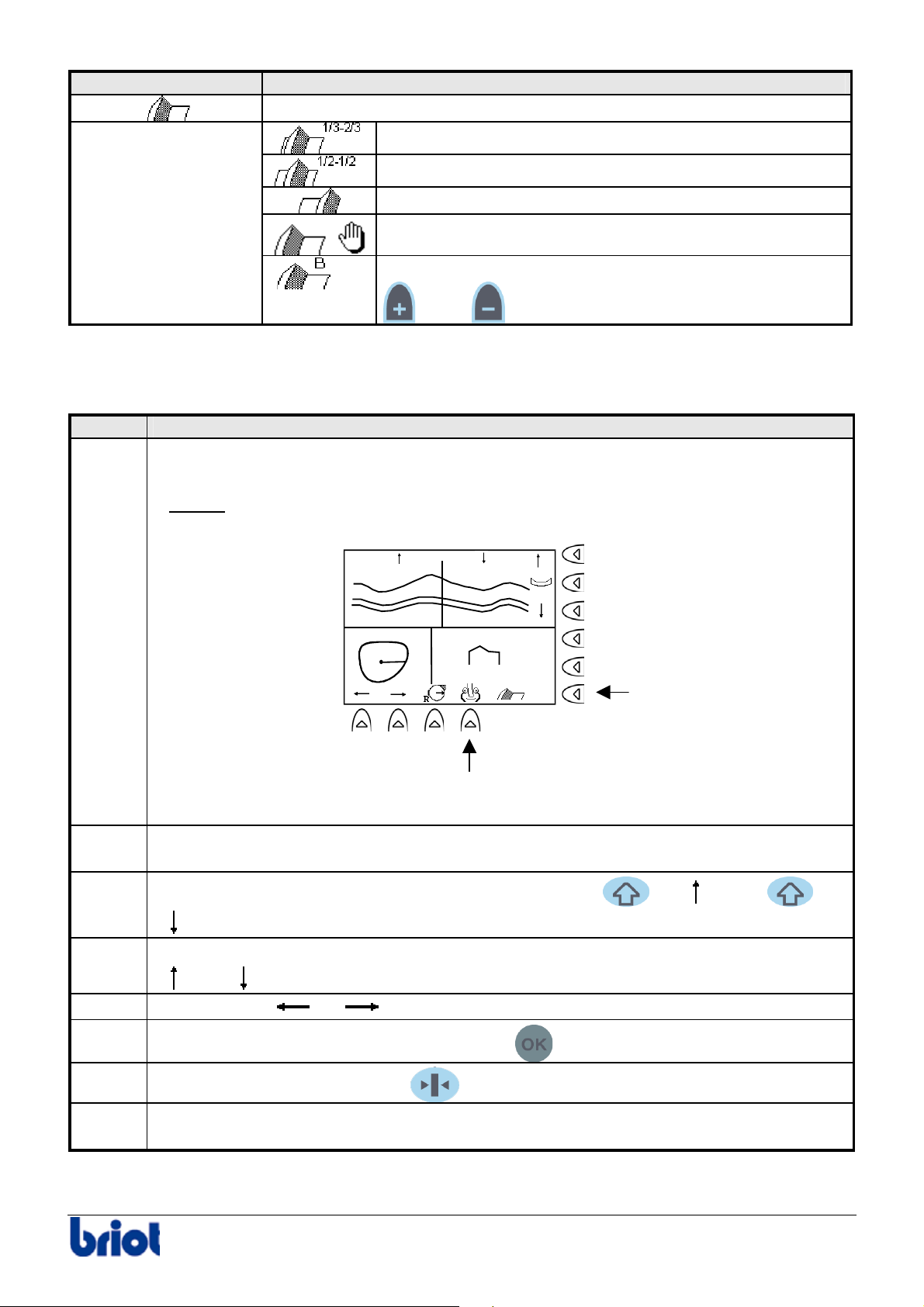
Make it possible to select one of the following bevel types:
1/3 2/3 Bevel
1/2 1/2 Bevel
Rear side bevel
Aesthetic bevel
Defined base bevel: value modifiable (from 1 to 9) by
05
and/or keys.
o Procedure
To control the position of the bevel after roughing and lens feeling cycles, proceed as follows:
Step Action
1
Once the roughing and lens feeling cycles are processed, it is possible to:
• modify the bevel type using the Fct5 key.
Result:
the bevel position is updated.
2
3
4
• feel the lens again aid of the Fct9 key.
1.48 2.97
4.45
1/3-2/3
Fct 5
Fct 9
Select the bevel point whose position will be modified (opposite point at 180° won’t
move).
Modify the bevel point at the position required aid of the
keys.
+ and/or +
Move forward the curve drawn by the bevel towards the front or the back, aid of the
and keys.
5
Using the keys
and , scan the periphery of the lens to view the cut of the lens.
6
When the bevel position is correct, press the
key to start edging the bevel.
7
8
Hold the lens whilst pressing the
Remove the lens from the edger without unblocking it so as to be able to retouch it after
key of the keypad to open the lens clamp.
checking the size and if necessary.
Silver FC 00 511 37
Page 43
Use : Standard use
Retouching a Lens
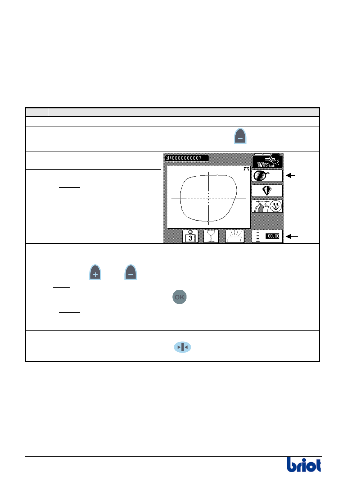
Prerequisites
To be able to rework a lens, you must first ensure that:
• the lens block has not been removed from its original lens placement;
• the edging parameters have not been altered.
Procedure
Follow the steps below to retouch a lens after edging.
Step Action
1
Place the lens in the edger again.
2
If the lens to retouch comes from the previous job, press the
following step.
3
Select the side to be retouched
with the Fct1 key.
4
Press the Fct5 key.
Result:
in inverse video.
the size value appears
key. If not, go to the
Fct 1
Fct 5
5
Enter the correction value using:
• the keypad or
• the
Note:
the correction value is always in a negative form and is limited to 5/10th mm.
and/or keys.
6
Close the visor manually and press the
Result:
The reworking cycle is performed.
key.
Warning! The reworking cycle can only be performed when the correction value
is inverse video.
7
When the reworking cycle is finished, open the visor manually.
Hold the edged lens whilst pressing the
key of the keypad (or the one located
on the left of the edging station for left-handers) to open the lens clamp.
38 Silver FC 00 511
Page 44

Use : Operational limits
Operational limits
SCANFORM™ UNIT
Frame tracing limits
• Height of the frame to 80 mm
• Height of the frame to 19.60 mm
Pattern tracing limits
• Height of the pattern to 52 mm
• Height of the pattern to 19 mm
LAY-OUT /BLOCKING UNIT
• Decentration 11 mm ; above this value, the effect of parallax is not corrected.
• Horizontal axis:
¾(x): 0 < (x) <14 mm
¾monocular pupillary distance: 14<1/2 PD<40 mm
• Vertical axis:
¾(y): if the value entered is < 11 mm, the decentration will operate in relation
to the geometric centre.
¾if the value entered is 11 mm, the decentration will operate in relation
to the height (Box or Mix).
EDGING STATION
• Material not to be used with the edger: Trivex®, if the edging wheel is not fitted.
• Diameter of the blank lens before edging: to 80 mm
• Minimum height of the shape: to 17.75 mm in glass and to 19.50 mm in bevel
• Blanck lens thicknesses:
¾Maximum (edge of the lens): 20 mm
¾Minimum (center of the lens): 0.9 mm
• Lifespan of the edging wheels:
¾Mineral Roughing: 8000 lenses
¾Organic Roughing: 50000 lenses
¾Finishing: 8000 lenses
¾Polishing: 10000 lenses
• Maximal radius of the lens so that it can be felt : r ≤ 43
MEMORY
• Memory capacity: 156 jobs (117 +39)
Silver FC 00 511 39
Page 45

Page 46

Maintenance
Page 47

Page 48

Maintenance
User maintenance
To keep your edger in perfect condition, we recommend you:
• to remove the glass and CR 39 dust daily, using clean water and a soft sponge or a brush so
as not to scratch the plastic surfaces.
• to remove the dust carefully from the Scanform™ tracer tip.
• to clean the edging wheels regularly.
• to clean the visor regularly.
• to change the screen protector when it is scratched or worn.
• to replace the lens feeler tip when it is bent.
• to change the water in the tank regularly if your machine operates in a closed circuit.
Silver FC 00 511 43
Page 49
List of accessories and consumables
ACCESSORIES
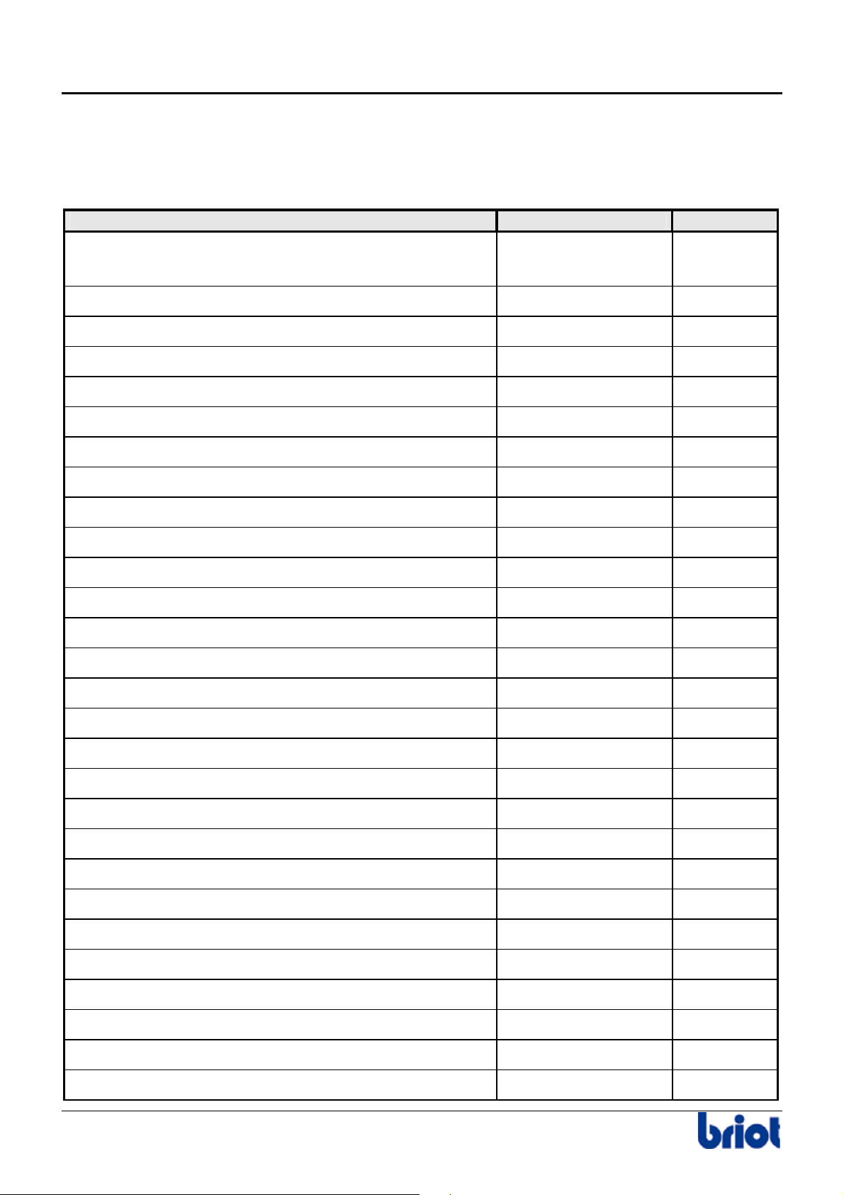
The following table lists the accessories delivered with your edger.
Accessory Briot Part Num. Quantity
User’s manual according to the country FC 00 393
FC 00 394
Case 01 64 044 1
Accura accessory box 11 77 029 1
Accura adjustment tool 14 04 199 1
Roughing cleaning disk 24 07 020 1
Finishing cleaning disk 24 07 021 1
Polishing cleaning disk 24 07 029 1
Double-ended tubular lamp flat ends 6.4x30 24V 3W 12 01 057 1
Oval Blocks (18 mm) 21 53 013 5
Large Blocks (25mm) 21 53 012 5
Block holder 19mm 11 90 406 1
Block holder 25mm 11 90 375 1
Adhesive pads (box of 1000) 60 21 005 1
1
Swivel lens clamping adaptor Ø 19mm 01 14 004 1
Swivel lens clamping adaptor Ø 25mm 01 14 005 1
Assembly 17/flat WECO for Accura 01 14 007 1
Swivel lens clamping socket washer - Ø 19mm 11 38 161 5
Swivel lens clamping socket - Ø 25mm 11 38 162 4
Set of blocks 01 64 015 1
Set of fuses 01 64 013 1
Gain adjustment tool 14 04 255 1
Scanform Offset/axis calibration frame 14 04 185 1
Lens to lens and pattern adjustment tool 14 04 191 1
Lens to lens offset adjustment tool 14 04 192 1
Lens feeler tip replacement tool 14 04 283 1
Lens to lens and pattern holder 11 90 517 1
Display window protector 11 22 154 1
Lens holder ring 02 20 150 1
44 Silver FC 00 511
Page 50
Maintenance
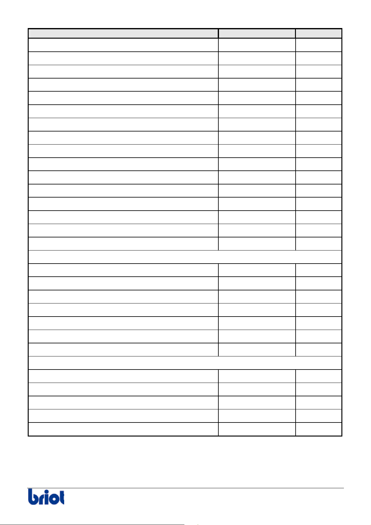
Accessory Briot Part Num. Quantity
Cover ¼ turn locking key 37 30 003 1
Fuse 10AT – 250 V – 6.3x32 22 29 052 2
Fuse 5AT – 250 V – 5x20 22 29 002 4
Fuse 25AT – 125V – 6.3x32 22 29 056 2
Fuse 3.15AT – 250V – 5x20 22 29 043 2
Fuse 2AT – 250V – 5x20 22 29 038 2
Lens feeler tip 11 38 181 2
Filter joint 20x27 21 62 153 1
Allen key of 2 14 01 003 1
Key 6 facets of 2.5 14 01 004 1
Key 6 facets of 3 14 01 005 1
Key 6 facets of 5 14 01 006 1
Key 6 facets of 1.5 14 01 009 1
Key 6 facets of 4 14 01 011 1
Key 6 facets of 6 14 01 012 1
Centering pad 02 22 034 1
CARDBOARD BOX
Evacuation sleeve 50 (standard version) 11 68 029 1
Evacuation sleeve 30 (standard version) 11 68 030 1
Out of box form FC 00 447 1
Silver unpacking instructions 1
Box of accessories 650x110x110 11 77 001 1
Plastic bag 100x130 21 40 010 1
Water supply hose 21 13 007 1
PACKING
Oregon pipe Ø 30 mm (standard version) 21 92 024 1
Oregon pipe Ø 50 mm (polycarbonate version) 21 92 066 1
Oregon pipe Ø 100 mm (polycarbonate version) 21 13 002 1
Protective cover 11 40 139 1
Silver FC 00 511 45
Page 51
CONSUMABLES
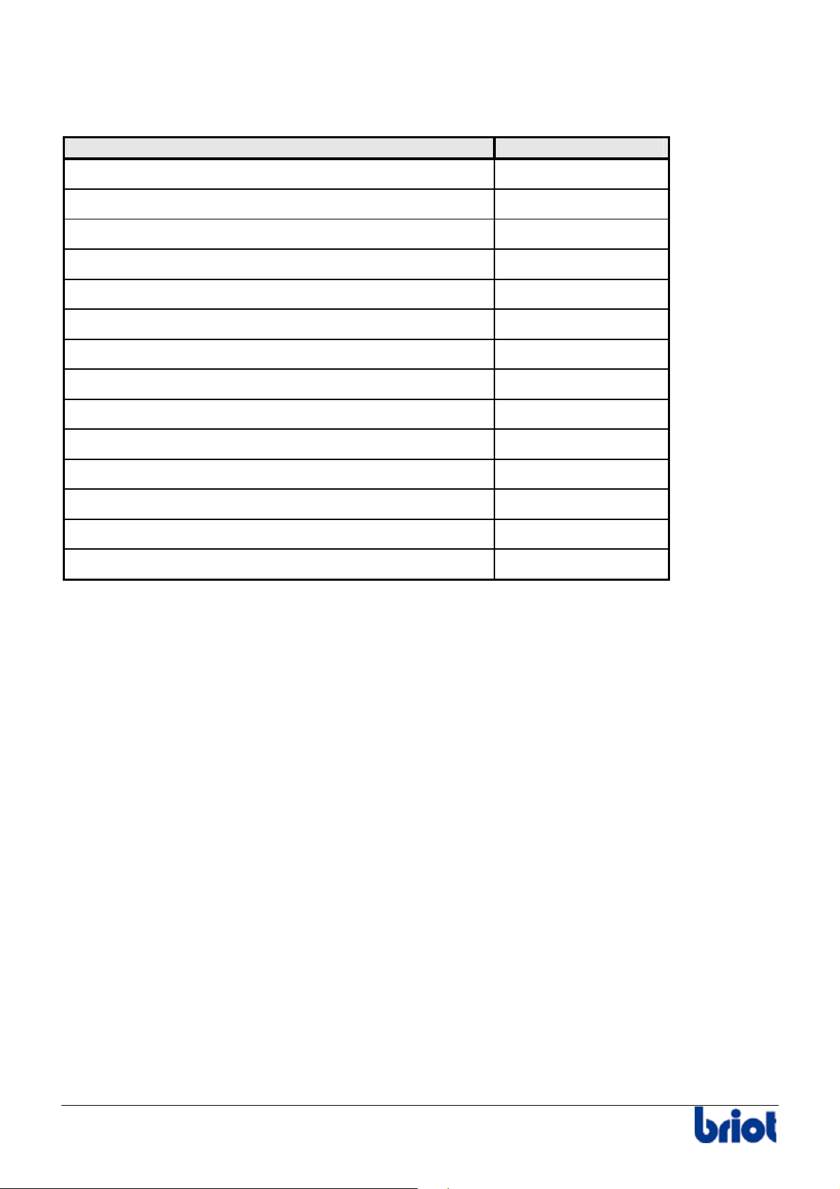
The following table shows certain consumables available in our equipment catalogue.
Consumable Briot Part Num.
Lens feeler tip 11 38 181
Roughing cleaning disk 24 07 020
Finishing cleaning disk 24 07 021
Polishing cleaning disk 24 07 029
Double-ended tubular lamp 12 01 057
Adhesive pads (box of 1000) 60 21 005
Accura display window protector 11 22 154
Swivel lens clamping adaptor Ø 19mm 01 14 004
Swivel lens clamping adaptor Ø 25mm 01 14 005
Assembly 17/flat WECO for Accura 01 14 007
Swivel lens clamping socket washer - Ø 19mm 11 38 161
Swivel lens clamping socket - Ø 25mm 11 38 162
Frame-clip tube large model 11 92 093
Frame-clip tube small model 11 92 074
46 Silver FC 00 511
Page 52
Maintenance : Settings and adjustments
Settings and adjustments
ADJUSTING THE SCREEN CONTRAST
Description
There are 3 types of adjustments to improve the visibility of the lens on the Scanform™ screen.
Type Function Possible Use
Inverse Colour Key Improve the visibility of the bifocal
segment
Screen Brightness Adjust the brightness of the
recorded shape with the screen
Polarizing View
Finder
Adjust the contrast of the lens with
the screen
Inverse Colour
The inverse colour may be changed at any time, by pressing the and keys.
Settings of the decentration
for near vision
Adapt to the ambient light in
the working lab
Improve view when decentering
of a dark lens
Result:
Notes:
Screen Contrast Adjustment Keys
•
•
the screen reverses color.
To return to black on white, press again the and keys.
+ : to darken the screen contrast
+ : to lighten the screen contrast.
Polarizing View Finder
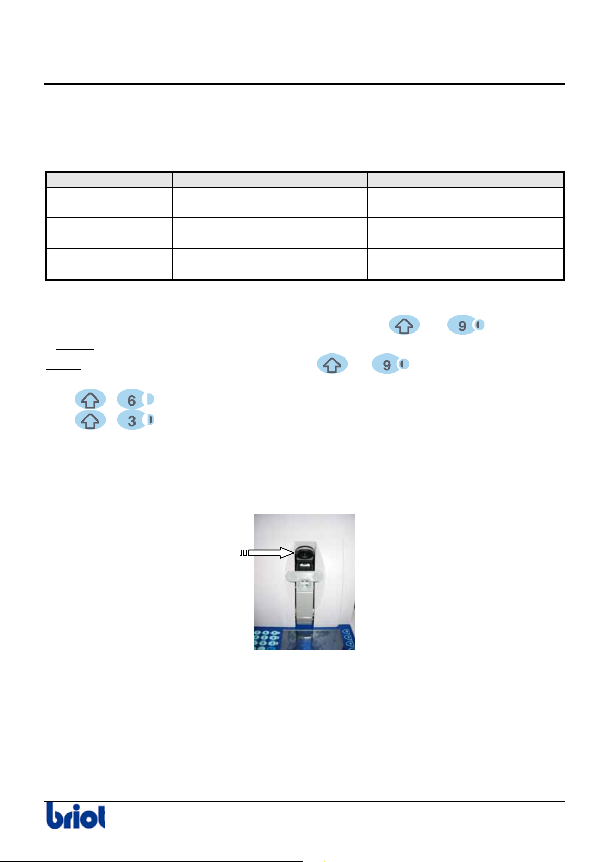
To adjust the brightness of the recorded shape with the screen, rotate the polarizing eyepiece
in either direction to suit you best.
Silver FC 00 511 47
Page 53
Maintenance : Settings and adjustments
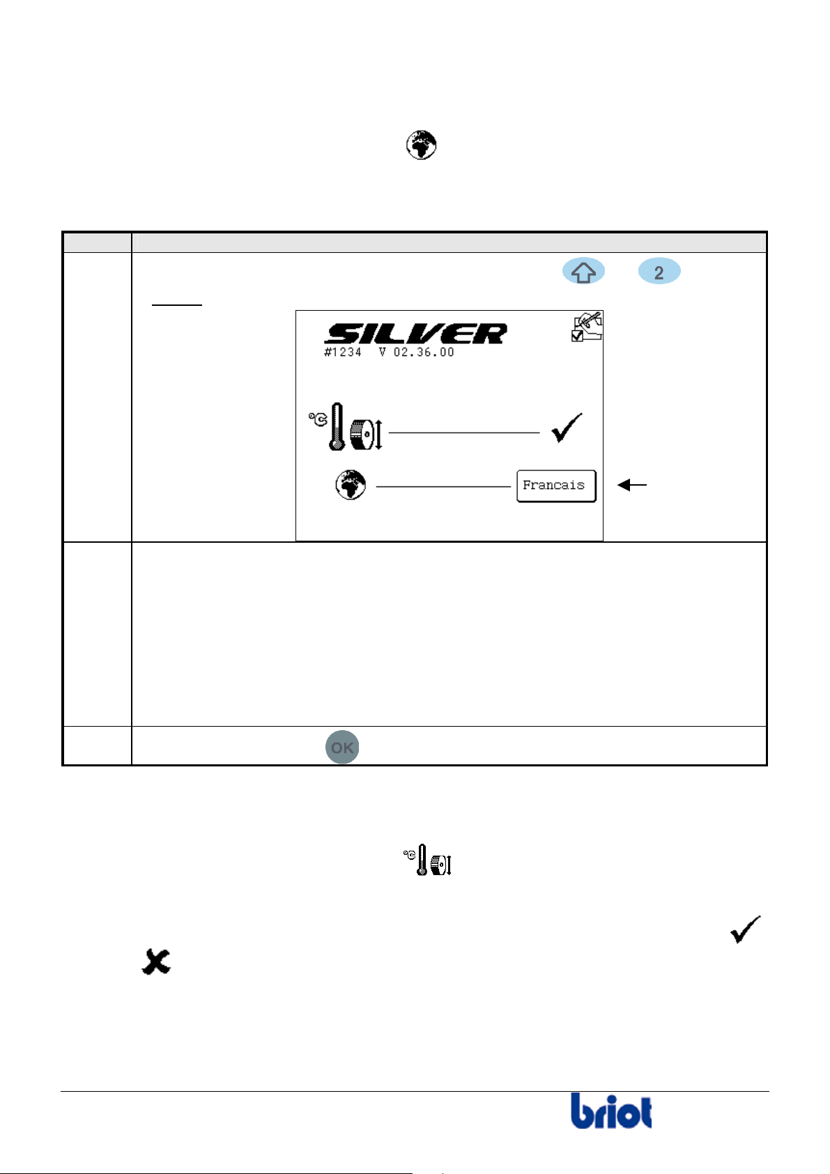
SELECTING A LANGUAGE
Icon
The icon linked to this Settings is the following: .
Procedure
Follow the steps below to select the language.
Step Action
1
When you are in tracing mode, press simultaneously the and keys.
2
3
Result:
the following screen is displayed.
Select your chosen language using the function Fct4.
Press this key until you obtain the language required:
• English
• Français
• Español
• Italiano
• Deutsch
• Other
Press three times on the
key to go back to the working mode.
Fct4
CHECKING IF THE TEMPERATURE COMPENSATION IS ACTIVATED/DEACTIVATED
Icon
The icon linked to this Settings is the following: .
Description
• On the screen above you can see whether the temperature compensation is activated ( )
or is not (
• When the temperature compensation is activated, the expansion of the edging wheels
due to the water temperature is automatically corrected.
• The temperature compensation is activated by default. To deactivate it, contact your retailer.
48
).
Silver FC 00 511
Page 54
Maintenance : Settings and adjustments
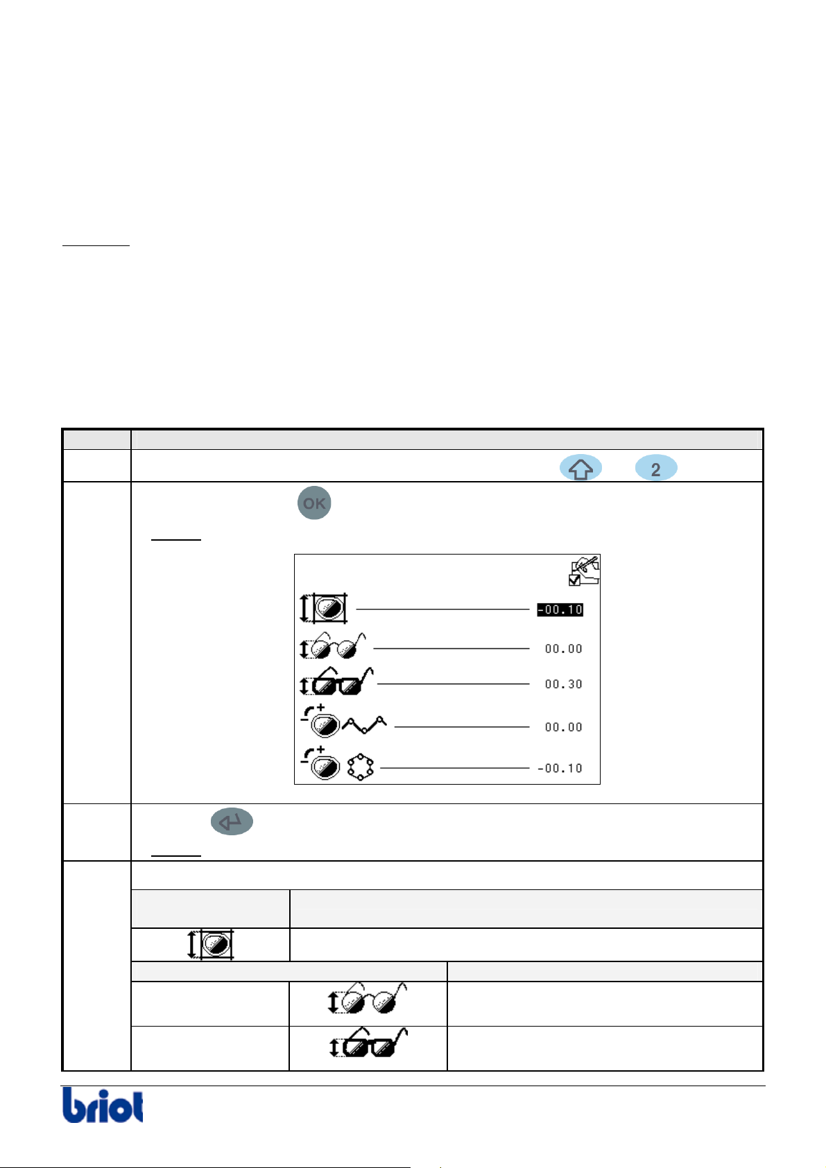
ADJUSTING THE SIZE CORRECTIONS
Description
The size corrections correspond to the positive or negative values added to the size of a lens. The
lens is edged to a size equal to the sum of the overall correction values, frame and lens material.
The value refers to the diameter of the lens to be edged.
Example:
The lens is then edged to the size:
Value saved + overall correction + frame correction + lens material correction
Condition
The machine must be stationary (neither being tracing nor edging).
Procedure
To adjust the size corrections, proceed as follows.
Step Action
the frame is traced: a value for the diameter of the side traced is saved.
1
When you are in tracing mode, press simultaneously the
and keys.
2
3
4
Press once on the key
Result:
the following screen is displayed:
.
Press the key to highlight the size correction to be changed.
Result:
the selected value appears in brighter color.
Enter the desired value with the keypad.
For overall
the value by default is equal to...
correction
0 mm
If the frame is in... the value by default is equal to...
Metal
Plastic
Silver FC 00 511 49
0 mm
0.30mm
Page 55
Maintenance : Settings and adjustments
Step Action
If the lens material is... the value by default is equal to...
CR39
polycarbonate
5
Press the key to validate your entry.
0 mm
+ 0.10mm
6
Go from the step 3 of this procedure until you adjust all the corrections.
7
Press several times on the
key to go back to the working mode.
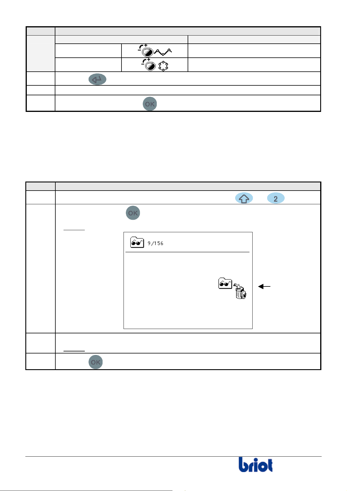
EMPTYING THE INTERNAL MEMORY
When the edger operates with the internal memory (neither with the memory buffer nor with an
external server), it is possible to delete all the jobs you have saved before.
Proceed as follows to empty the internal memory.
Step Action
1
2
When you are in tracing mode, press simultaneously the and keys.
Press twice on the key
Result:
the following screen is displayed.
.
3
4
Press the function key Fct3.
Result:
Press the
all the jobs have been deleted.
key to confirm the deletion and/or move to the following adjustment.
Fct3
50
Silver FC 00 511
Page 56
Maintenance : Settings and adjustments
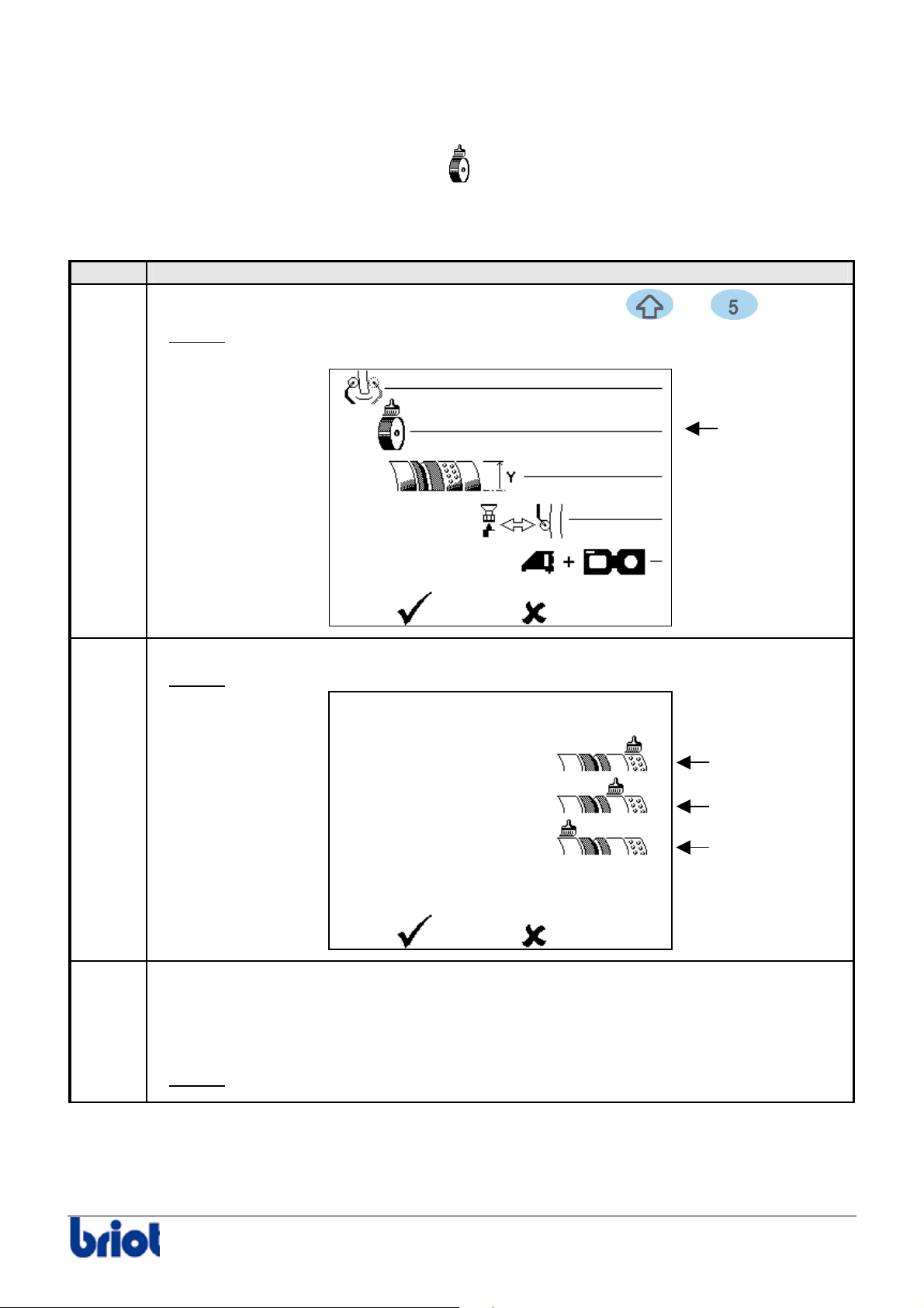
DRESSING THE WHEELS
Icon
The icon linked to this Settings is the following: .
Procedure
Follow the steps below to dress a wheel.
Step Action
1
When you are in tracing mode, press simultaneously the
and keys.
2
Result:
the following screen is displayed.
Select the line Automatic dressing using the function Fct1.
Result:
The following screen is displayed:
Fct1
Fct 1
3
Select the wheel to be dressed with the function keys:
• Fct1 : glass roughing wheel
• Fct2 : finishing wheel
• Fct3 : polishing wheel
Result:
The following screen is displayed (with Fct1):
Fct 2
Fct 3
Silver FC 00 511 51
Page 57
Maintenance : Settings and adjustments
Step Action
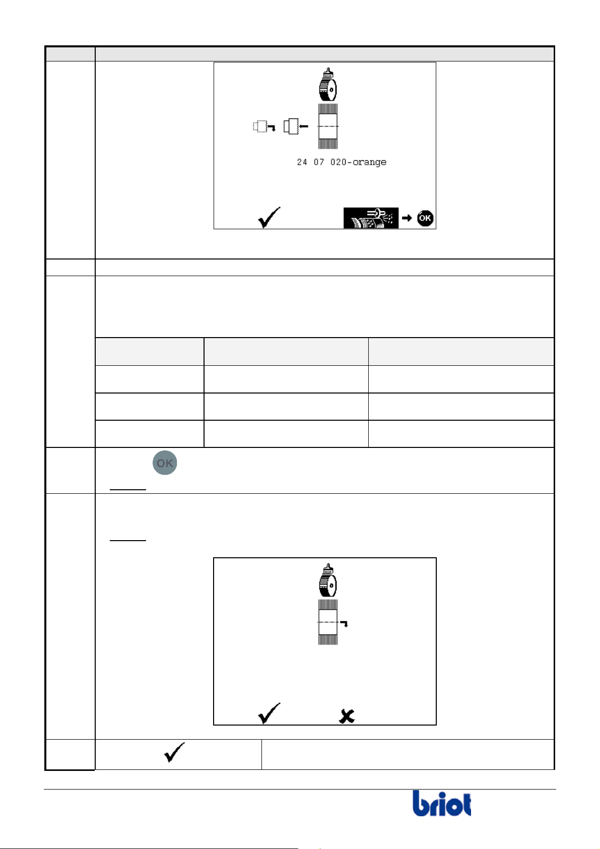
Caution! Each wheel requires a specific dressing wheel.
4
5
Mount the large connectors.
Load the dressing disk adapted to the wheel to dress and contained in the accessory
box.
Type of dressing
Reference Color
disc
Glass roughing 24 07 020 orange
6
7
Plastic roughing 24 07 021 white
Polishing 24 07 022 grey
Press the
Result:
Dressing is performed. The screen displays “Wheel dressing in progress”.
key.
Once dressing is finished, open the visor manually.
Then remove the disc from the edger.
Result:
The following screen is displayed:
52
7
If you select
the screen shown step 2 is displayed. Select another
,
wheel to dress.
Silver FC 00 511
Page 58
Maintenance : Settings and adjustments
Step Action
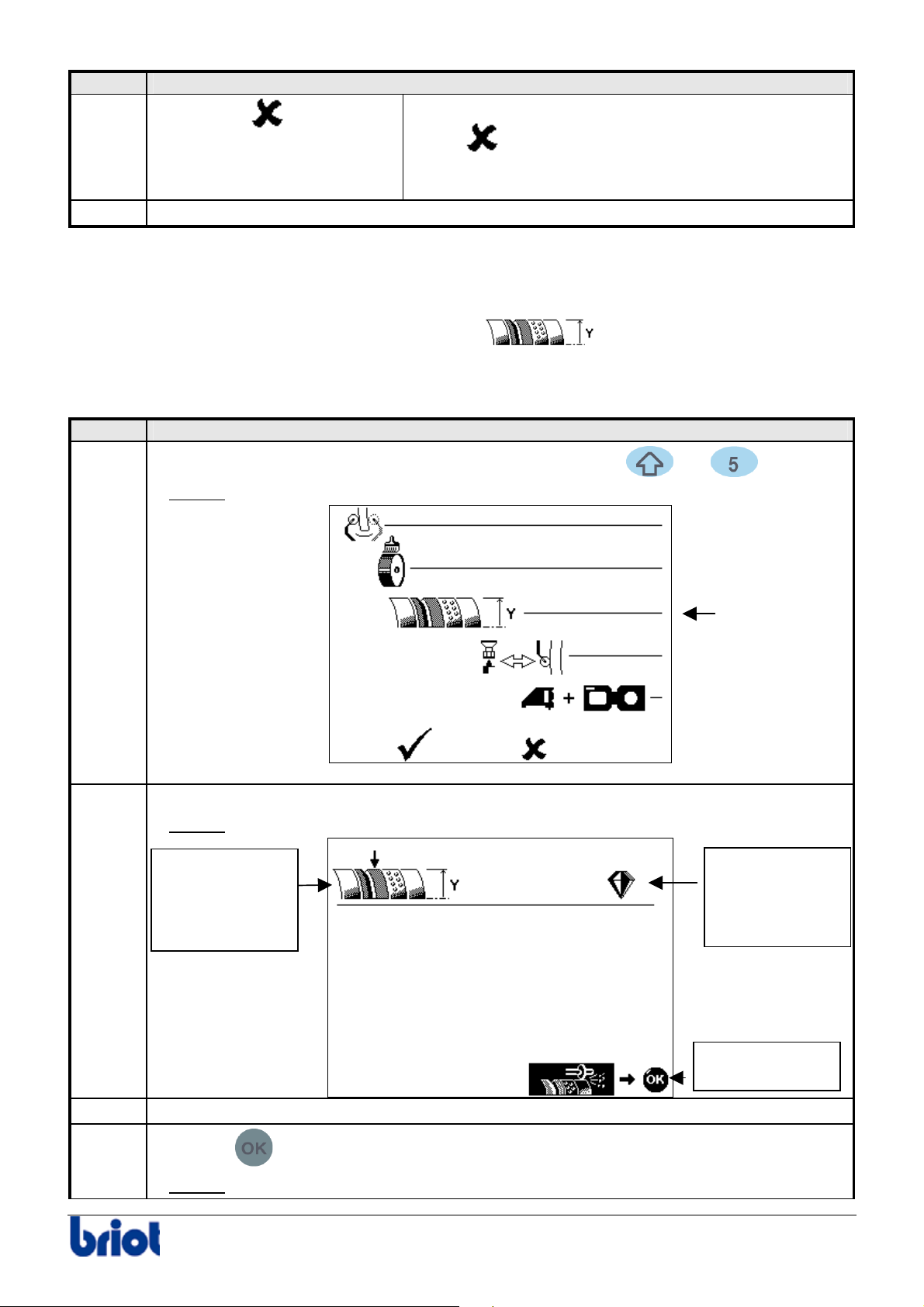
If you select
,
the screen shown at step 2 is displayed.
Select
again to leave the automatic dressing of
the edging wheels and go back to the screen shown
at step 1.
8
Adjust the sizes (see paragraph Size adjustment (reset sizes) below).
ADJUSTING THE LENS SIZES (RESET SIZES)
Icon
The icon relative to this adjustment is the following: .
Procedure
Follow the steps below to adjust sizes.
Step Action
1
When you are in tracing mode, press simultaneously the
and keys.
2
Result:
the following screen is displayed.
Select the line Size adjustment with Fct2.
Result: the following screen is displayed.
Type of edging
wheel.
Here, glass finish
Fct2
Type of lens to
be used for the
adjustment.
Here, mineral.
3
4
To edge,
press OK.
Insert a mineral lens with a diameter to 40 mm.
Press the
Result:
Silver FC 00 511 53
the lens is edged on the rimless part of the finishing wheel.
key.
Page 59
Maintenance : Settings and adjustments
Step Action
5
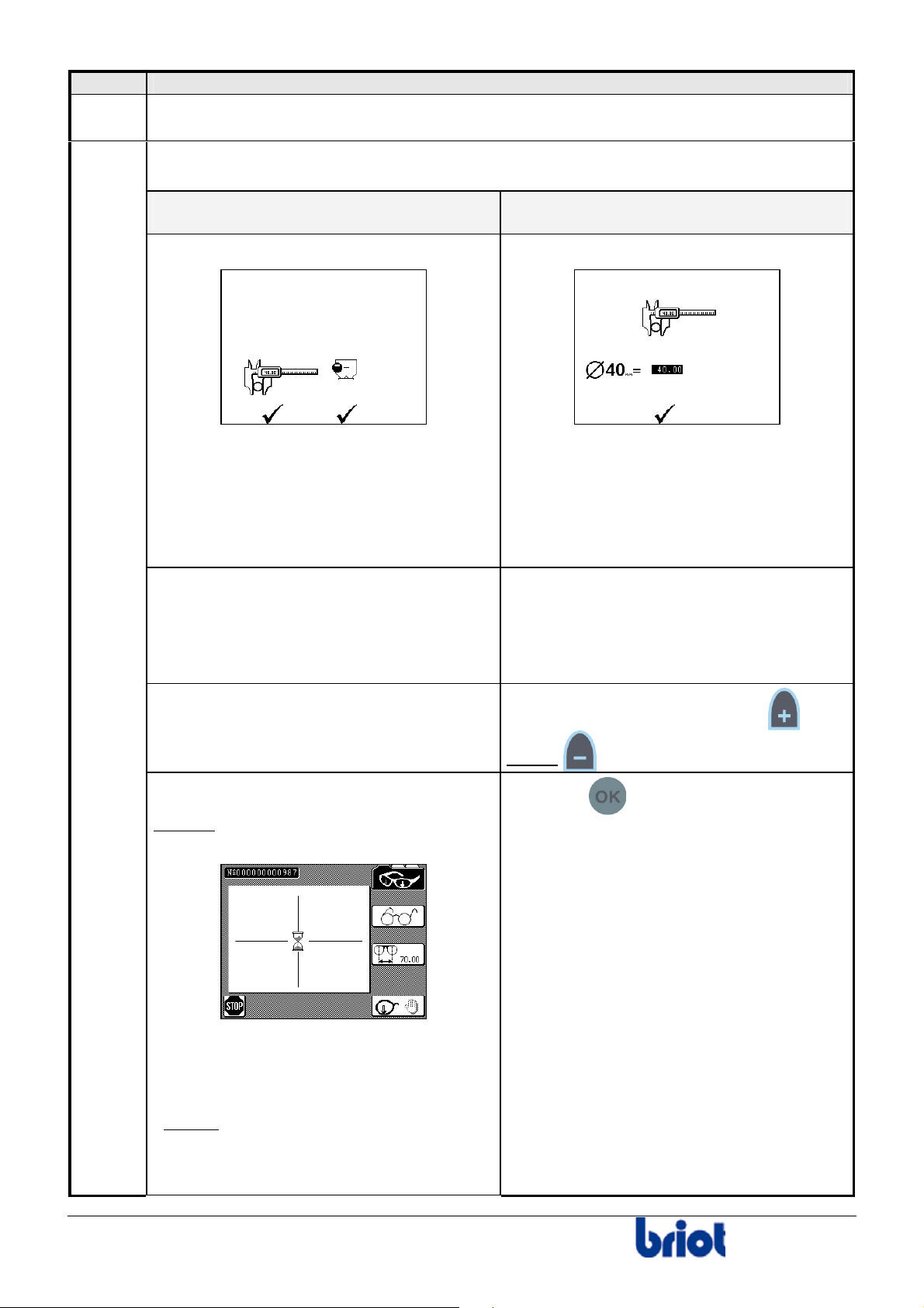
When the lens is edged, remove it from the edging chamber and measure it with
a slide caliper.
6
Measure the diameter of the lens.
2 possibilities:
The Scanform™ was detected when
you switched on the machine.
The following screen is displayed:
The Scanform™ was not detected
when you switched on the machine.
The following screen is displayed:
2 possibilities to measure the diameter of
the lens :
• Use a slide caliper;
OR
• Use the Scanform™.
To work with a slide caliper, press Fct
7 and refer to the step described opposite.
To work with the Scanform™, follow the
instructions below.
Mount the edged lens to the pattern holder
and put it in the Scanform™.
THEN press Fct 9.
Result : The following screen is displayed
while the lens is being traced:
The diameter of the lens can only be
measured with a slide caliper.
Take a slide caliper and measure the
diameter of the lens.
Enter the measured value using
and/or
(or with the keyboard).
Press the key to validate your entry.
54
Note:
It is possible to stop the tracing.
To do so, press Fct 6.
Result :
adjustment of the selected lens type is
displayed .
the screen with regard to the size
Then process the tracing again.
Silver FC 00 511
Page 60
Maintenance : Settings and adjustments
Step Action
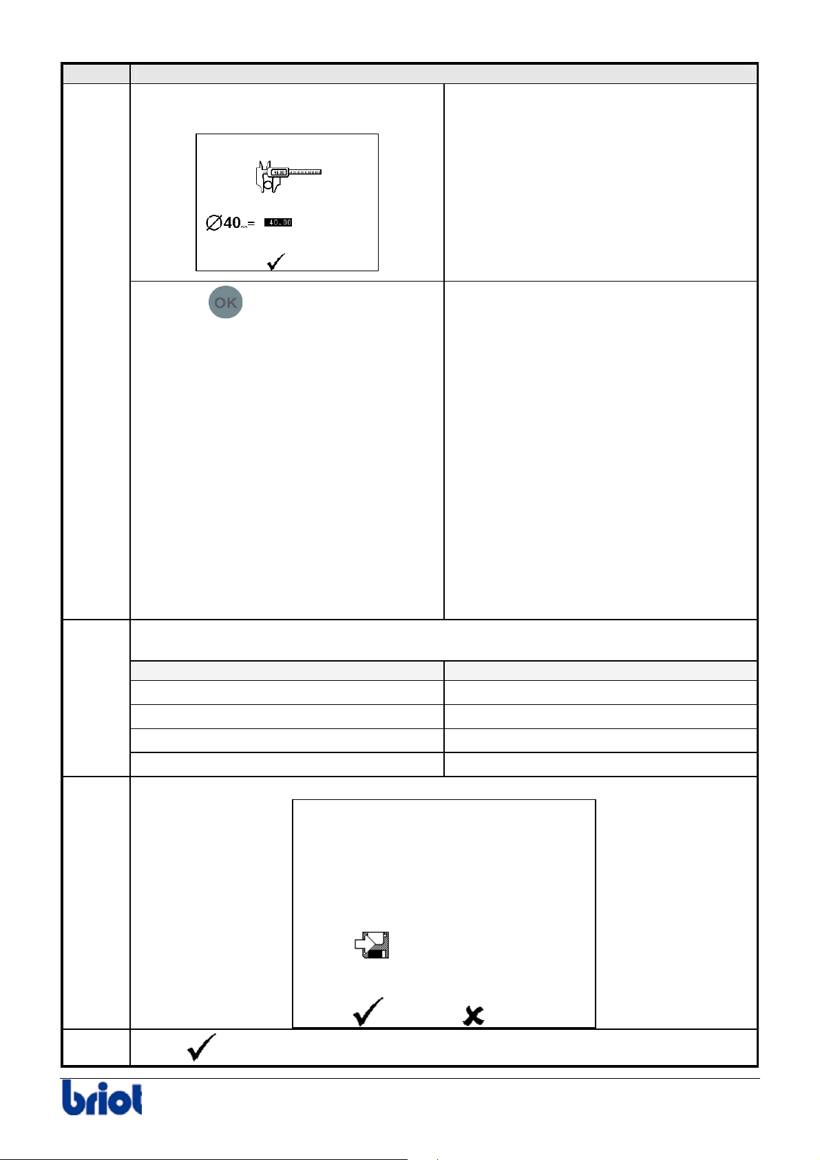
Once the lens is traced, the following
screen is displayed:
7
8
Press the
key to confirm the
diameter of the lens traced by the
Scanform™.
Caution! If there is a difference of +/- 2 mm
between this diameter and the standard
one, the message “Incoherent adjustments”
is displayed.
9 Confirm it.
9 Switch off the machine, then switch
it on again (the size adjustments
you have just done will not be
saved).
9 Adjust the Scanform™.
9 Adjust the lens sizes again.
If you still have problems with size
adjustments, please contact your
retailer.
Proceed to the adjustment of the next sizes: follow the instructions displayed on
the screen.The order is as follows:
For the edging wheel… use the following type of lens
1. Glass roughing
2. Plastic roughing
3. Bevel Finishing
4. Glass polishing
Mineral, ∅ > 50 mm
Plastic, ∅ > 50 mm
Mineral, ∅ > 40 mm
Plastic, ∅ > 40 mm
When the sizes are adjusted, the following screen is displayed:
9
Select
Silver FC 00 511 55
and save your adjustments.
Page 61

Page 62
Maintenance : Settings and adjustments
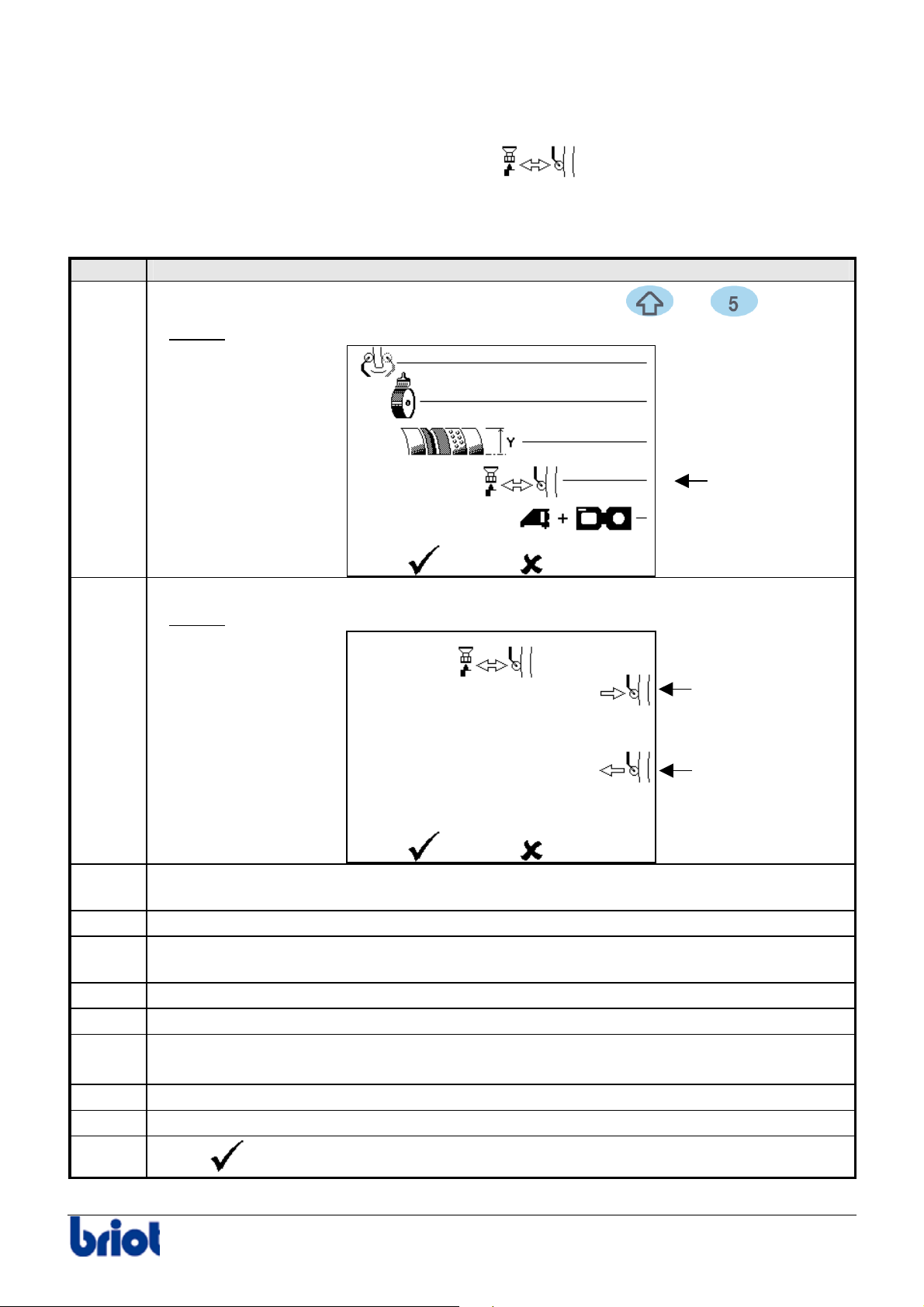
CHANGING THE LENS FEELER TIP
Icon
The icon associated with this change is the following: .
Procedure
To change the lens feeler tip, proceed as follows.
Step Action
1
When you are in tracing mode, press simultaneously the and keys.
2
Result:
the following screen is displayed.
Select the line Changing the lens feeler tip using the function Fct 3.
Result: the following screen is displayed.
Fct3
Fct1
Fct3
3
Insert the lens feeler tip replacement tool in the edging chamber and place it on the
wheel assembly carefully.
4
5
Move the lens feeler arm to the right using function Fct1.
Hold the lens feeler tip and insert an optician’s screwdriver in one of the slits at the
base of the lens feeler tip.
4
5
6
Push the lens feeler tip towards the top so as to release it from its holder.
Remove the lens feeler tip.
Put in a new lens feeler tip.
Caution! Do not press the lens feeler arm.
7
8
Move the lens feeler arm to the left using function Fct3.
Remove the lens feeler tip replacement tool.
9
Select
to confirm the change of lens feeler tip.
Silver FC 00 511 57
Page 63
Maintenance: Settings and adjustments
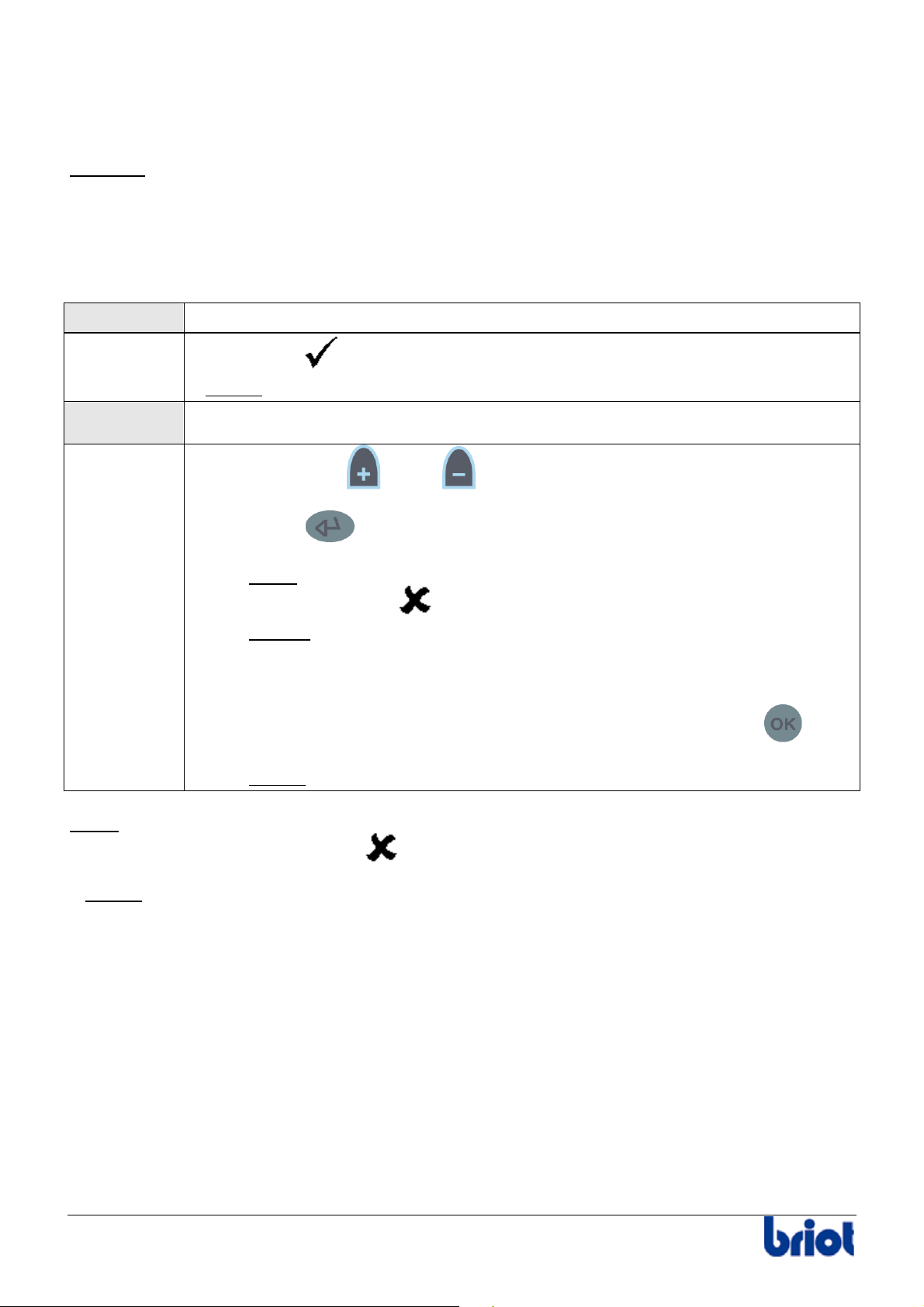
ADJUSTING THE SCANFORM™
Preliminary notes
To adjust the Scanform™, you are directed to confirm or change the displayed values.
Example:
The displayed values correspond to the last values memorized.
These values can be changed when they appear in brighter color.
Two cases:
Case 1 The displayed value(s) correspond(s) to that (those) of your adjustment tool
Case 2 The value, or at least one of the two values, does not correspond to that
R40.01
Select directly
Result:
the adjustment starts.
.
of the adjustment tool.
1. Press the keys
and/or in order to display the value engraved on the
adjustment tool.
2. Press the
key to confirm the displayed value.
Note : If you erroneously confirm an incorrect pattern size, cancel your
action by selecting
Result:
You leave the adjustment in progress and return to the first
.
Scanform™ adjustment screen. Enter or confirm the values again.
3. Start the procedure again if you need to change another value.
4. When the value(s) of the tool has (have) been confirmed, press the
to start the gain adjustment.
Result:
the adjustment starts.
Note :
adjustment in progress stops, select
It is impossible to interrupt an adjustment in progress. When the movement of the
.
Result: You leave the adjustment in progress and return to the first Scanform™ adjustment
screen. Enter or confirm the values again.
key
58 Silver FC 00 511
Page 64
Maintenance: Settings and adjustments
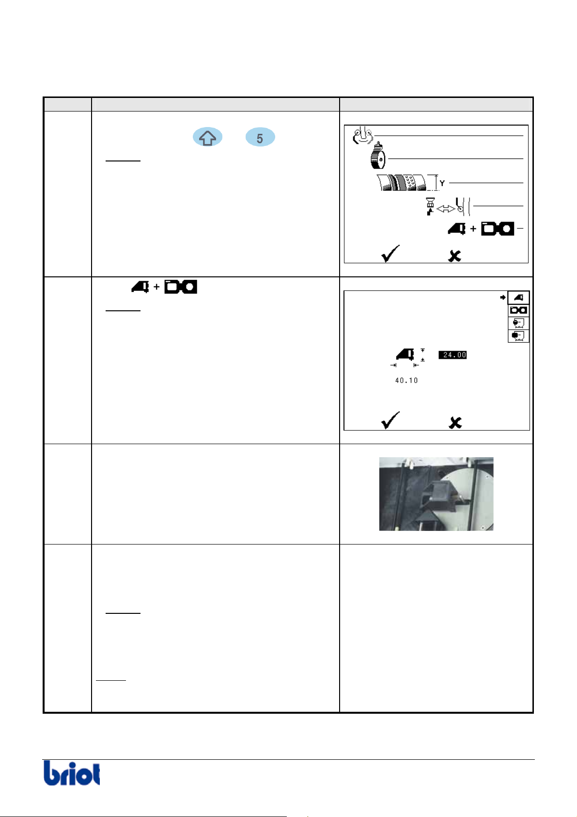
Procedure
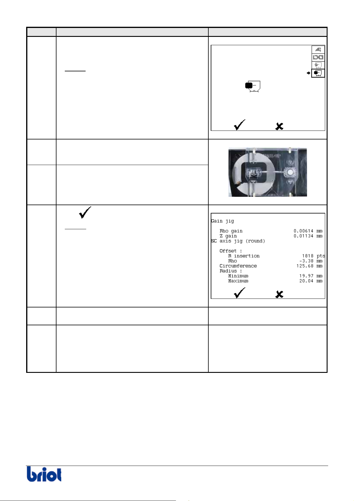
To adjust the Scanform™, proceed as follows.
Step Action Illustration
1
When you are in tracing mode, press
simultaneously the
and keys.
2
Result:
the Scanform™ initializes and the
adjustment dialogue screen is displayed.
Select
Result:
the Scanform™ initializes and the
using the function Fct4.
following screen is displayed.
3 Insert the adjustment tool n° 14 04 190 on the
turret protector.
4
Change or confirm the length and height of the
gain adjustment tool (Refer to paragraph
Preliminary notes above).
Result:
when you have confirmed the
values, the gain adjustment is performed.
The tracer measures the positions r and R
as well as h1 and h2.
Note :
if you interrupt the adjustment, start it
again from step 1 of the present procedure.
-
Silver FC 00 511 59
Page 65
Maintenance: Settings and adjustments
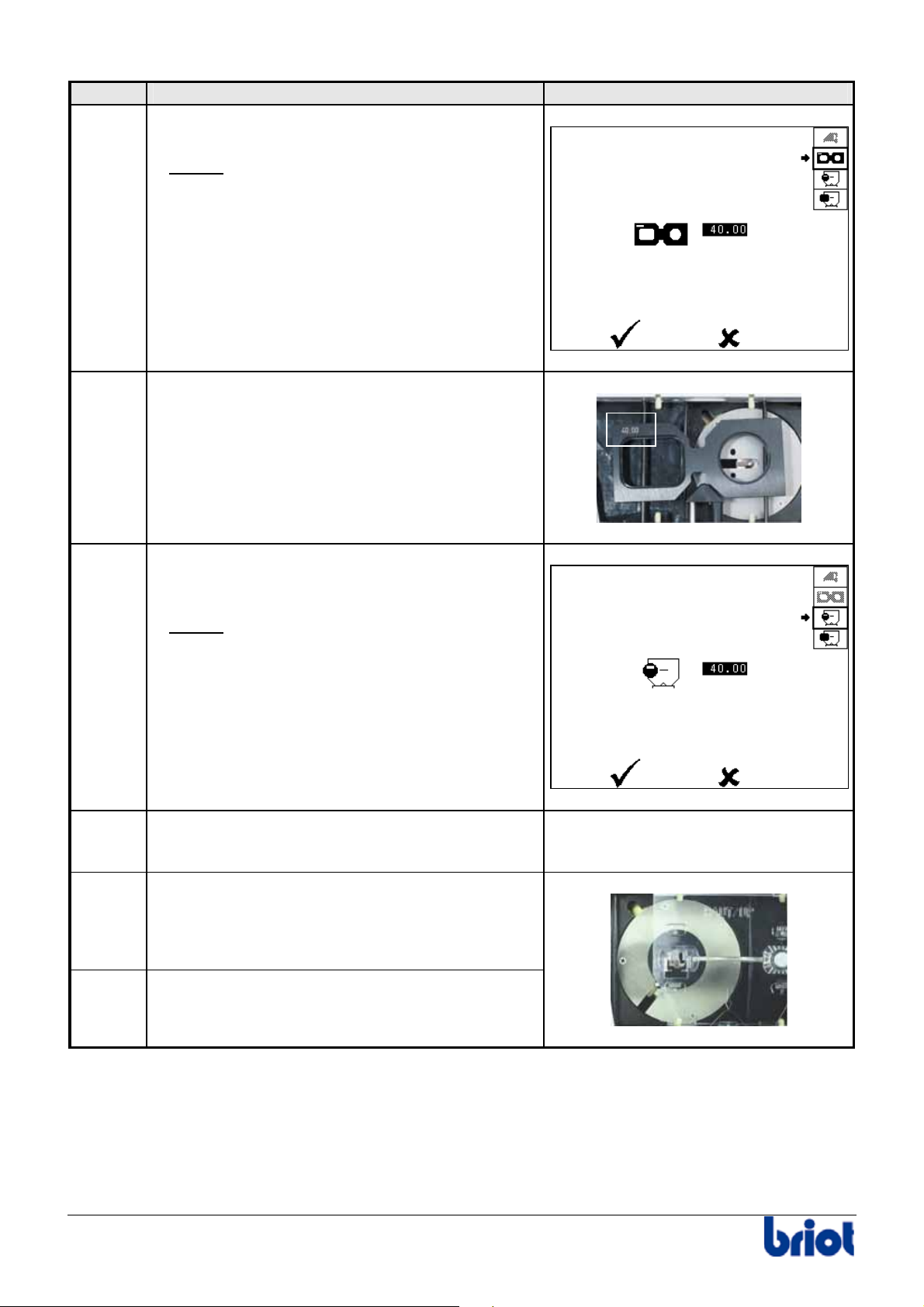
Step Action Illustration
5
When the gain adjustment is finished, remove
the gain adjustment tool.
Result:
the following screen is displayed.
6
Insert the adjustment tool (the round right side)
n° 14 04 185 on the frame holder.
7
8
9
Change or confirm the displayed value (Refer
to the paragraph Preliminary notes above).
Result:
When you have confirmed the value,
the round form and then the rectangular
form are traced.
Then, the screen shown opposite is
displayed.
When the adjustment is finished, remove tool
n° 14 04 185.
Place the round pattern n° 14 04 192 (Ø40 mm)
on the pattern holder.
-
10
Insert the pattern holder on the frame holder.
60 Silver FC 00 511
Page 66
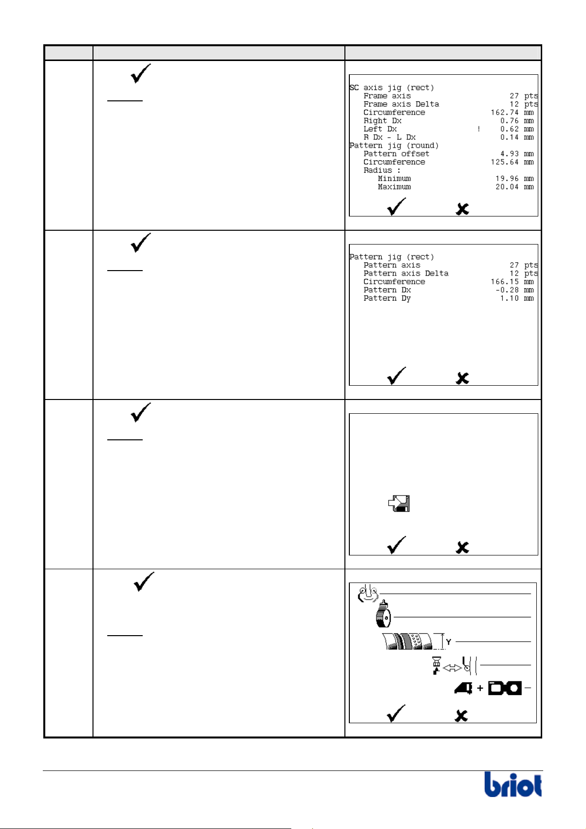
Maintenance: Settings and adjustments
Step Action Illustration
11
Change or confirm the displayed value. (Refer
to the paragraph Preliminary remarks above).
Result:
When you have confirmed the size
of the pattern, the machine traces the round
pattern. Then the screen shown opposite
is displayed.
12
Place the rectangular pattern n° 14 04 191
on the pattern holder.
13
Insert the pattern holder on the frame holder.
14
15
16
Select
Result:
.
the machine traces the rectangular
pattern.
Then, the screen shown opposite is
displayed.
When the adjustment is finished, remove the
pattern and the tool n° 14 04 191.
Consult the screen shown at step 14.
The presence of an exclamation mark displayed
between the measurement name and the
measurement value indicates an adjustment
beyond the tolerance levels.
-
-
Silver FC 00 511 61
Page 67
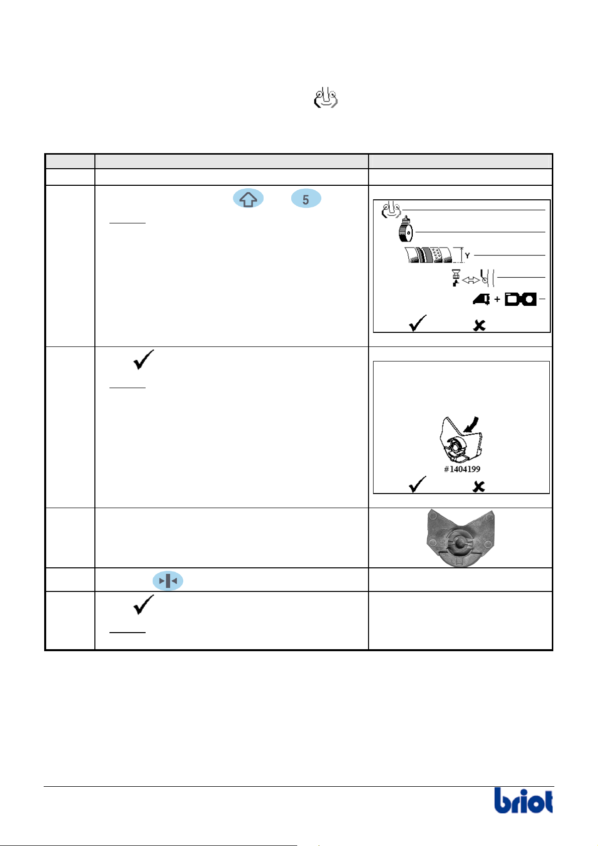
Maintenance: Settings and adjustments
Step Action Illustration
17
Select
Result:
.
the screen shown opposite
is displayed.
18
Select
Result:
.
the screen shown opposite
is displayed.
19
20
Select
Result:
.
the screen shown opposite
is displayed.
Select
to save the adjustment of
the Scanform™.
Result:
the screen shown opposite
is displayed.
62 Silver FC 00 511
Page 68

Maintenance: Settings and adjustments
Step Action Illustration
21
Select
Result:
to leave the adjustment dialogue.
the machine re-initializes and then
-
the tracing screen is displayed.
Silver FC 00 511 63
Page 69
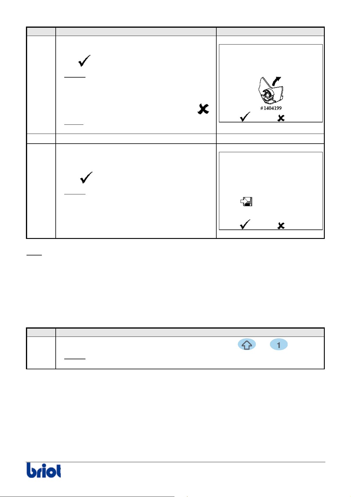
Maintenance : Settings and adjustments
ADJUSTING THE LENS FEELING
Icon
The icon relative to this adjustment is the following: .
Procedure
To adjust the lens feeling, proceed as follows.
Step Action Illustration
1
2
Access the tracing screen.
Press simultaneously the and keys.
-
3
4
Result:
the screen shown opposite is
displayed.
Select
Result:
.
the screen shown opposite
is displayed.
Put adjustment tool n° 14 04 199 on the lens
adapter shaft (left side).
5
6
Press the key to close the lens clamp.
Select
Result:
.
the tracing adjustment performs
-
-
automatically.
64 Silver FC 00 511
Page 70
Maintenance : Settings and adjustments
Step Action Illustration
7
When the adjustment is finished, the screen shown
opposite is displayed.
Select
Result:
.
The adjustment is confirmed and
the lens clamp opens automatically.
Note
.
-
8
9
If you do not wish to confirm the adjustment, select
Result:
lens clamp opens automatically.
The adjustment is not confirmed BUT the
Remove tool n° 14 04 199.
When you have confirmed the adjustment,
the screen shown opposite is displayed.
Select
Result:
to save the adjustment.
the adjustment is saved and the
machine re-initializes.
Note
This adjustment influences the bevel position. A badly performed adjustment can cause the
machine to produce poor quality work as a result.
CONSULTING THE STATISTICS
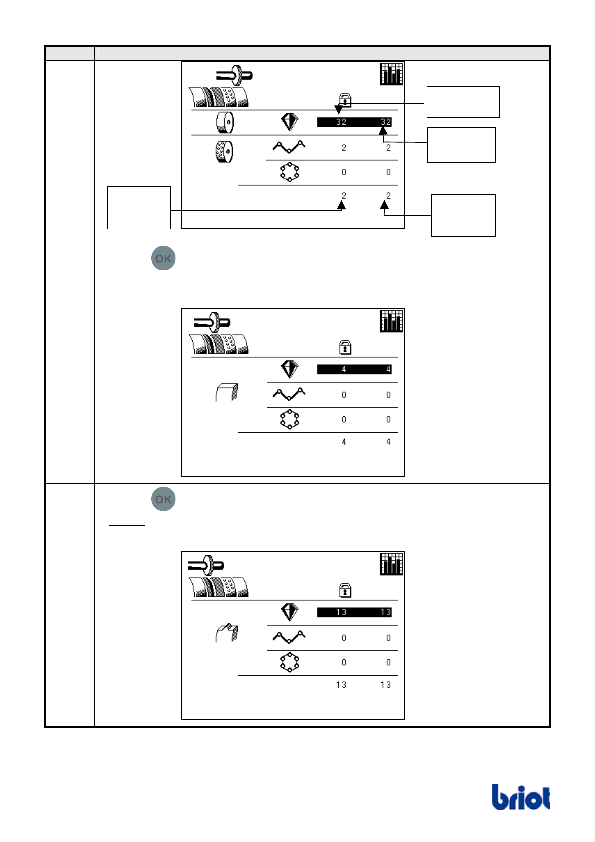
Lens counters
Procedure
To consult the lens counters, proceed as follows.
Step Action
1
When you are in tracing mode, press simultaneously the
Result:
the screen with regard to the counting of lenses roughed down is
displayed.
and keys.
Silver FC 00 511 65
Page 71
Maintenance : Settings and adjustments
Step Action
Total counter
and permanent
Partial
counter
2
3
Partial
counter
total
Press the
Result:
the screen with regard to the counting of lenses with a glass finish is
key.
displayed.
Press the
key.
Partial
counter
total
Result:
the screen with regard to the counting of lenses with a bevel finish is
displayed.
66 Silver FC 00 511
Page 72
Maintenance : Settings and adjustments
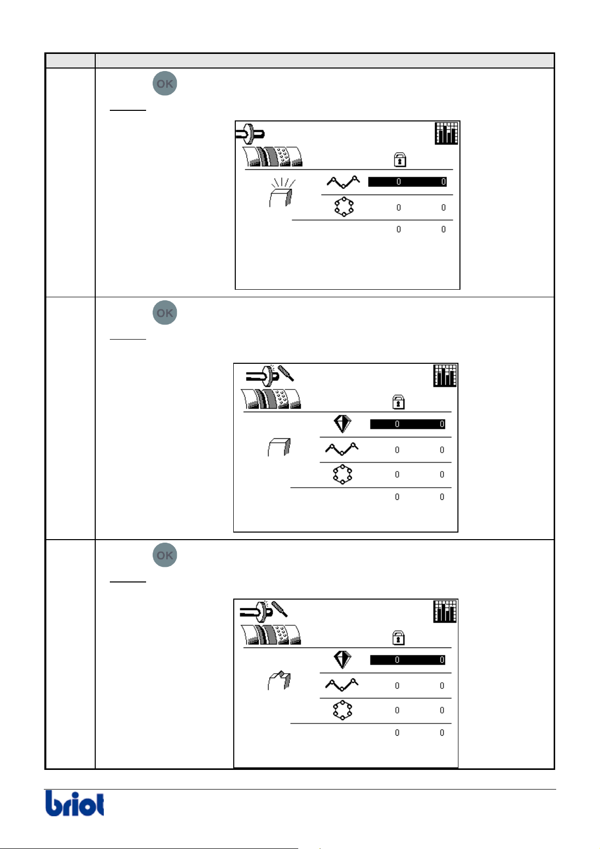
Step Action
4
Press the
key.
5
Result:
Press the
Result:
the screen with regard to the counting of polished lenses is displayed.
key.
the screen with regard to the counting of lenses retouched with a glass
finish is displayed.
6
Press the
Result:
the screen with regard to the counting of lenses retouched with a bevel
key.
finish is displayed.
Silver FC 00 511 67
Page 73
Maintenance : Settings and adjustments
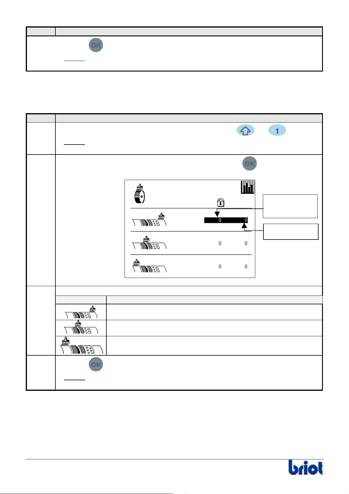
Step Action
7
Press the
key
Result:
the statistics screen with regard to wheel dressing is displayed (refer to the
following paragraph, step 1).
Wheel dressing
Procedure
Proceed as follows to consult the statistics with regard to wheel dressing.
Etape Action
1
2
When you are in tracing mode, press simultaneously the
Result:
the first statistics screen is displayed (refer to the previous paragraph, step
1).
Access the following screen by pressing several times on the
and keys.
key.
Total and
permanent
counter
2
3
Consult your chosen data.
Icon Meaning
Number of mineral roughing wheel dressings performed.
Number of finishing wheel dressings performed.
Number of polishing wheel dressings performed.
Press the
Result:
the statistics screen with regard to the lens feeler adjustment is displayed
key.
(refer to the following paragraph, step 1).
Partial counter
68 Silver FC 00 511
Page 74
Maintenance : Settings and adjustments
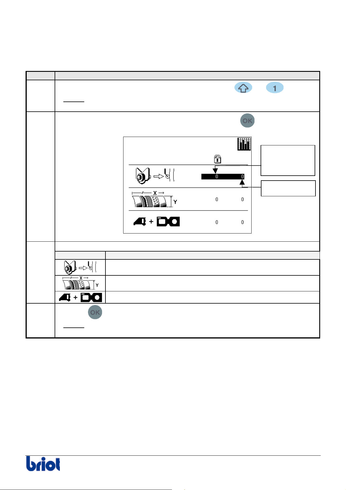
Lens feeler, lens size and Scanform™ adjustments
Procedure
Proceed as follows to consult the statistics with regard to the lens feeler, lens size and
Scanform™ adjustments.
Step Action
1
When you are in tracing mode, press simultaneously the and keys.
2
2
3
Result:
the first statistics screen is displayed (refer to the paragraph lens counters
above, step 1).
Access the following screen by pressing several times on the
Consult your chosen data.
Icon Meaning
Number of lens feeler adjustments performed.
Number of size adjustments performed.
Number of Scanform™ adjustments performed.
Press the
key.
key.
Total and
permanent
counter
Partial counter
Result:
the statistics screen with regard to the type of tracing is displayed
(refer to the following paragraph, step 1).
Silver FC 00 511 69
Page 75
Maintenance : Settings and adjustments
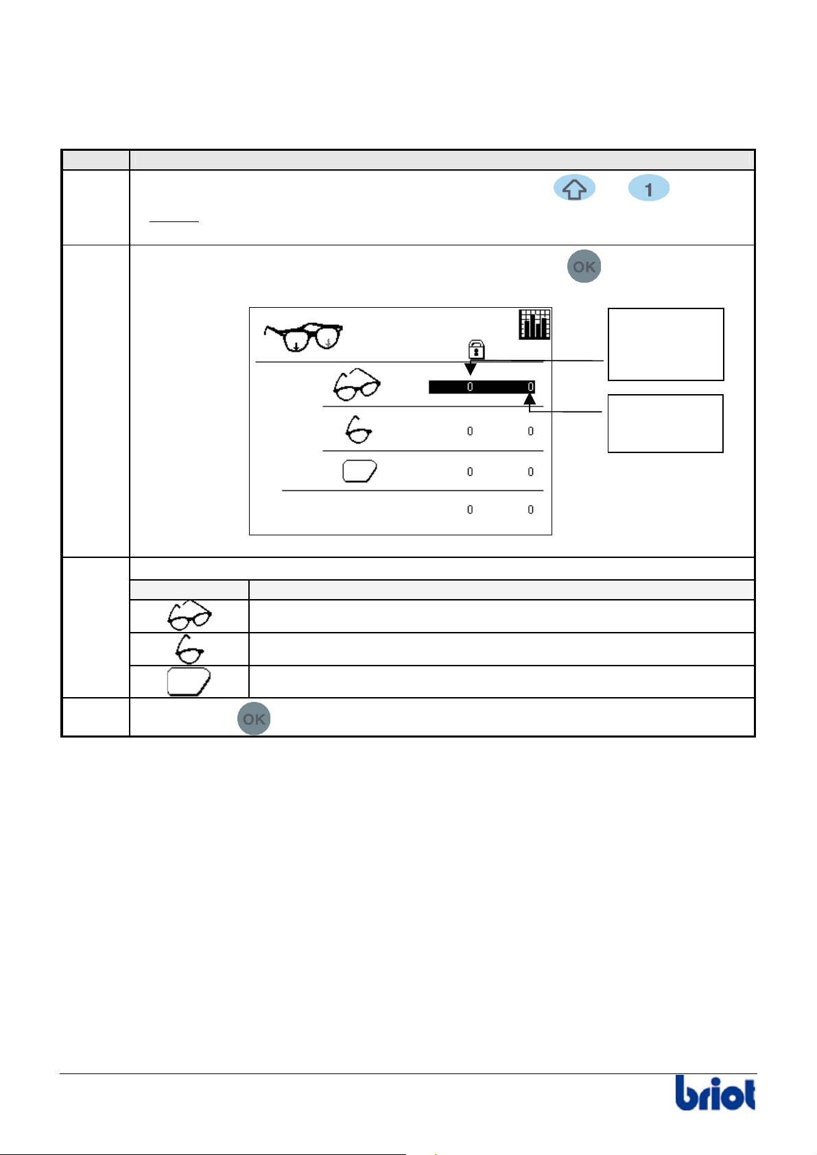
Type of tracing
Procedure
Proceed as follows to consult the statistics with regard to the type of tracing.
Step Action
1
When you are in tracing mode, press simultaneously the and keys.
Result:
the first statistics screen is displayed (refer to the paragraph lens counters
above, step 1).
2
Access the following screen by pressing several times on the
key.
Total and
permanent
tracing
counter
Partial tracing
counter
2
Consult your chosen data.
Icon Parameter
Number of frames traced in full, i.e. left side + right side.
Number of frames partially traced, i.e. one side only.
Number of patterns traced.
3
Press the key
to go back to the tracing screen.
70 Silver FC 00 511
Page 76
Maintenance : messages
Messages
MESSAGE TYPES
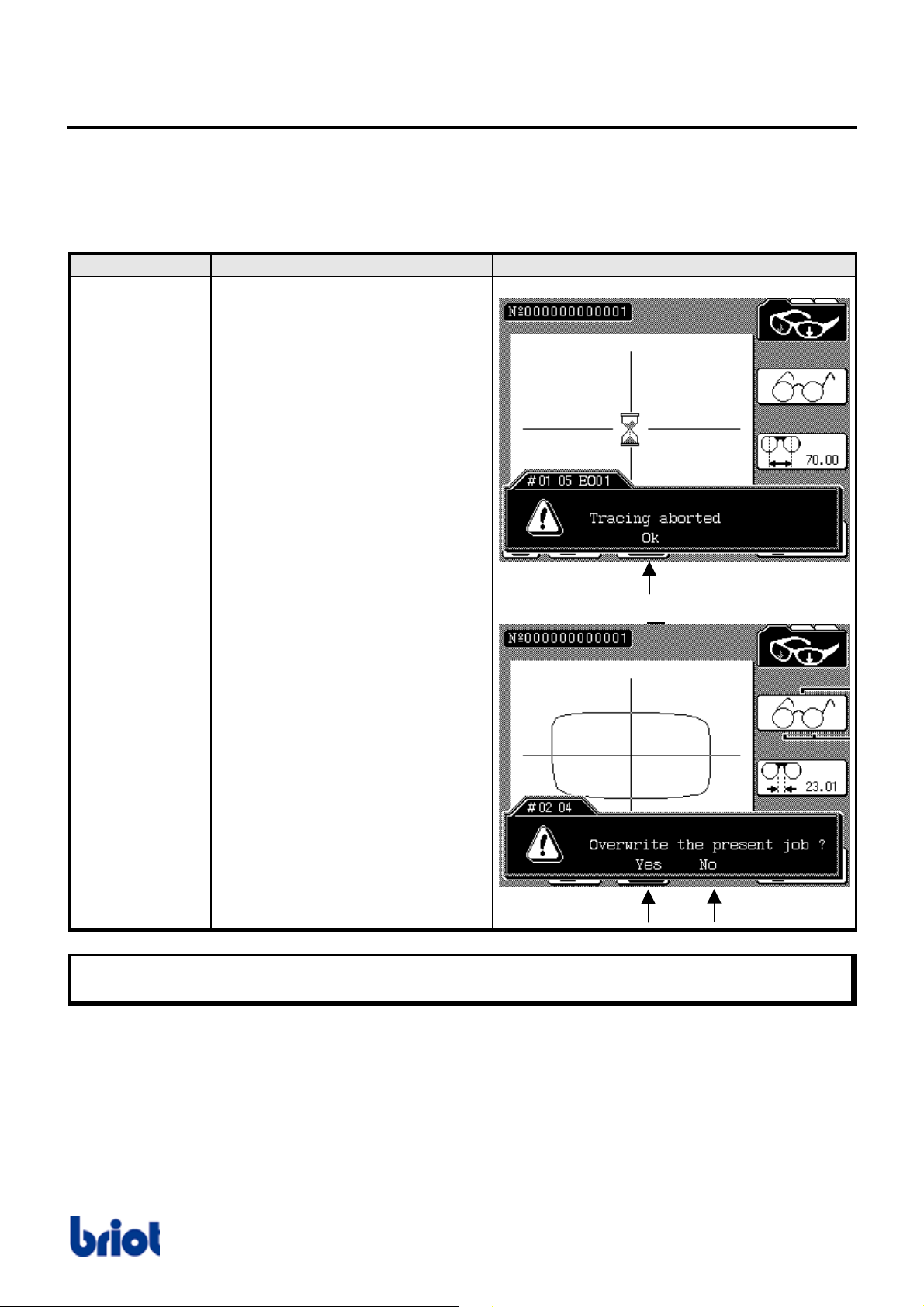
The following table describes the types of messages with regard to the operator dialogue.
These messages appear in brighter color and are displayed at the bottom of the screen.
Type Description Acquittal
Warning Attract your attention to an
illogical procedure or a minor
event.
By selecting OK.
Question Indicate that you must choose
between two solutions.
• While the message is displayed, the operator dialogue is inhibited.
• The message area disappears from the screen when the message is acknowledged.
By selecting Yes or
No.
Or
Silver FC 00 511 71
Page 77
Maintenance : messages
LIST
Origin: Scanform™
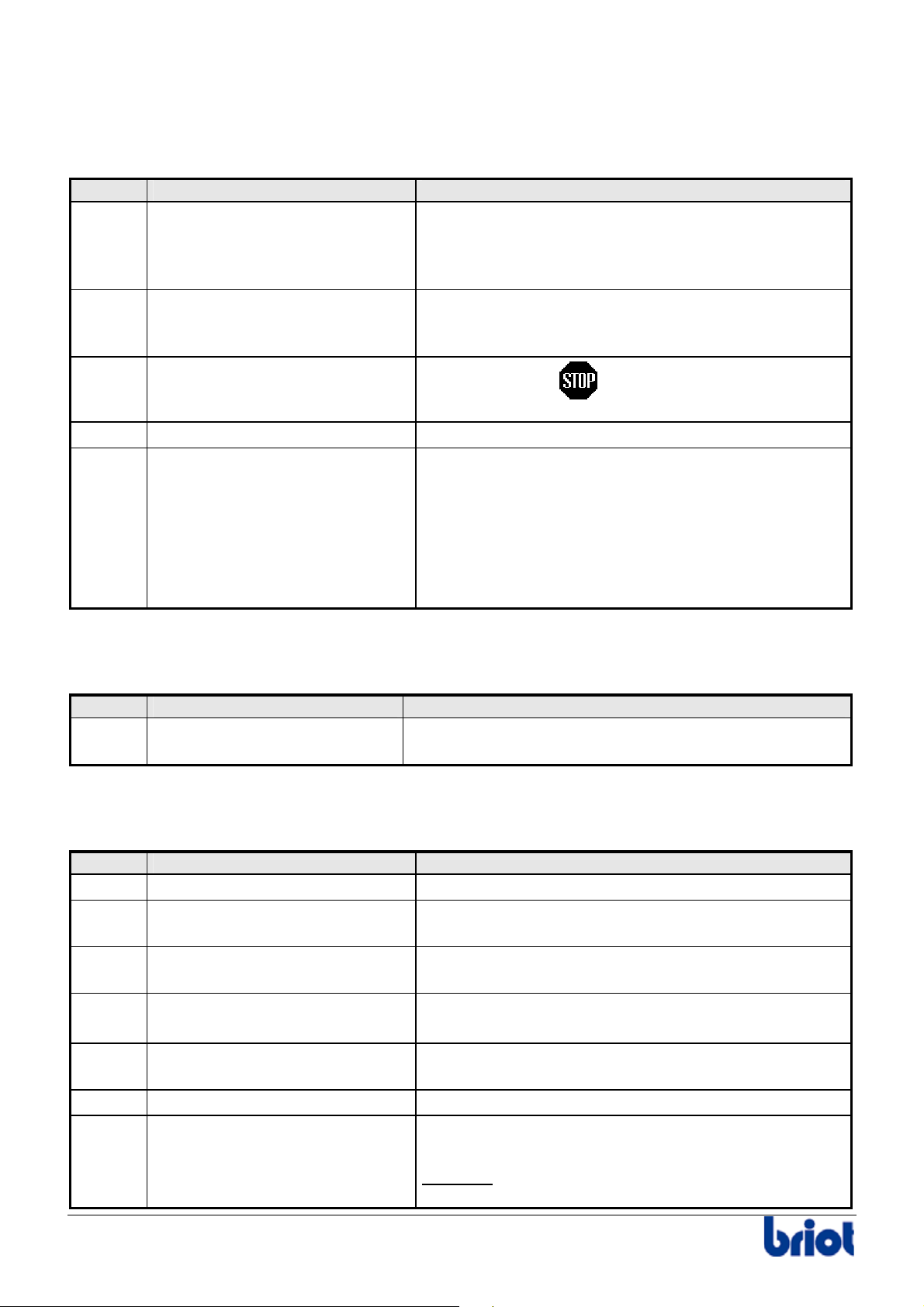
The following table lists the messages that can be displayed while using the Scanform™.
N° Message Cause
01 01 Deactivate the Scanform™ ? The Scanform™ does not initialize correctly. One of
the movements does not operate properly. You can
deactivate the Scanform™ and work with the shapes
saved in the flash memory or on the server.
01 03 Incorrect coherence control An incorrect setting has been produced during a
Scanform™ adjustment. Repeat this adjustment
and ensure it is properly performed.
01 05 Tracing aborted
01 09 No Scanform Link problem with the scanform™.
01 10 Shape closure prob., continue? The frame has possibly moved during tracing.
Origin: Lay-out
You pressed the
key during tracing for
example.
The calculation algorithm can correct this problem
but the lens edged may not match the frame shape
(size a little too large)
• Yes: correct the problem and carry on.
• No: stop the process and trace the frame
again.
The following table shows the messages that can be displayed in the lay-out mode.
N° Message Cause
02 03 Unknown job Call of one job number being neither the current job
nor the previous job aid of the keypad.
Origin: Tracing
The following table shows the messages that can be displayed in the tracing mode.
N° Message Cause
03 01 Memory full More than 117 jobs in the memory
03 04 Overwrite the current job? You are trying to start the tracing cycle of a job that
has already been traced.
03 05 Edging previous job While you create the job n° 3 whereas the job n° 1
is in edging cycle.
03 06 Overwrite the job in memory? The job number to save already exists in memory.
If not, the job is saved under another number.
03 08 Edging present job You try to scan again the present job during the
edging of this job.
03 09 Are you sure? If yes, the current job is deleted
03 11 Incompatible edger config. Incompatibility problem between job parameters and
edger setting.
Example
machine not equipped with TP wheel.
: job with Polycarbonate lenses on a
72 Silver FC 00 511
Page 78
Maintenance : messages
Origin: Edging
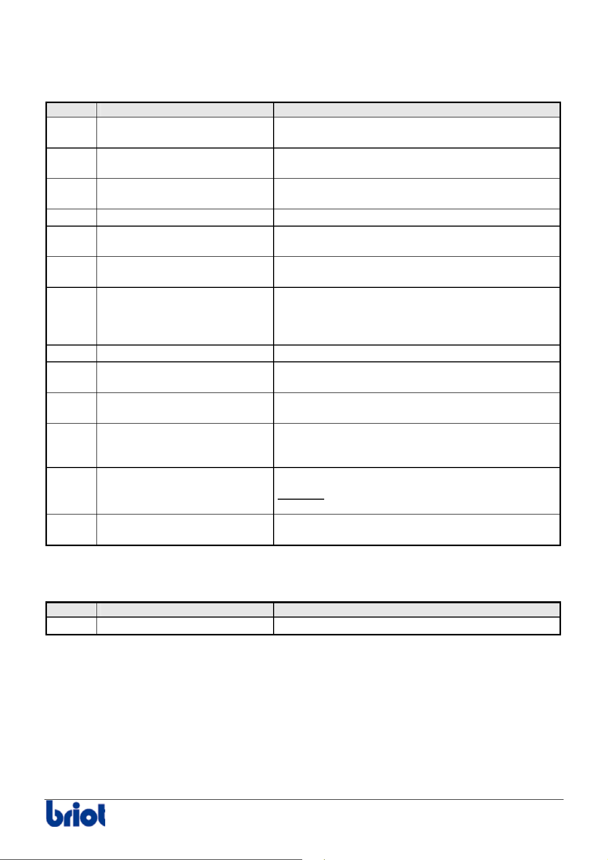
The following table shows the messages that can be displayed in the edging mode.
N° Message Cause
04 01 Retouch impossible A retouch is required when a lens has not yet been
edged.
04 04 Small adapters mounted? Request for confirmation of job of small adapter
model (Ø19 mm).
04 05 Lens too small for shape Lens too small or too decentered in comparison with
the shape.
04 06 Radius < 10 mm Shape too small. (Try to work in boxing mode.)
04 07 Re edge same lens? Lens edging from a job on the screen already
edged.
04 08 Bevel too much at the back Top of the bevel more than 5 mm from the front
face.
04 10 Do you want to continue? This message appears when the edging time
exceeded the limit of the machine (8 min).
The operator has the choice to continue or stop the
edging process.
04 11 Lens too thick for rimless Lens thickness higher than 10.4 mm.
04 12 Finishing impossible Finishing time greater than 3 min (carriage contact
problem).
04 14 Impossible edge Problem on the main motor. Rotation speed too low
or null.
05 06 Bevel top out lens
Continue?
During automatic bevel, the machine detects that the
bevel may go out of the lens edge. Shall we finish
the lens?
05 07 Lens feelers : Aberrant spots Irregular points detected during lens tracing.
Example
: for a half-moon lens, the adhesive
has not been cut before blocking.
05 12 Small flat adapter mounted? The frame shape requires Ø17mm adapters. Make
sure it is mounted before continuing.
Origin: Extension card
The following list shows the messages linked to the extension card.
Type Message Cause
06 02 Job not found The frame recalled does not exist on the server.
Silver FC 00 511 73
Page 79

Page 80

Annexes
Page 81

Page 82

Annex A Operation in recirculating mode
Page 83

Page 84
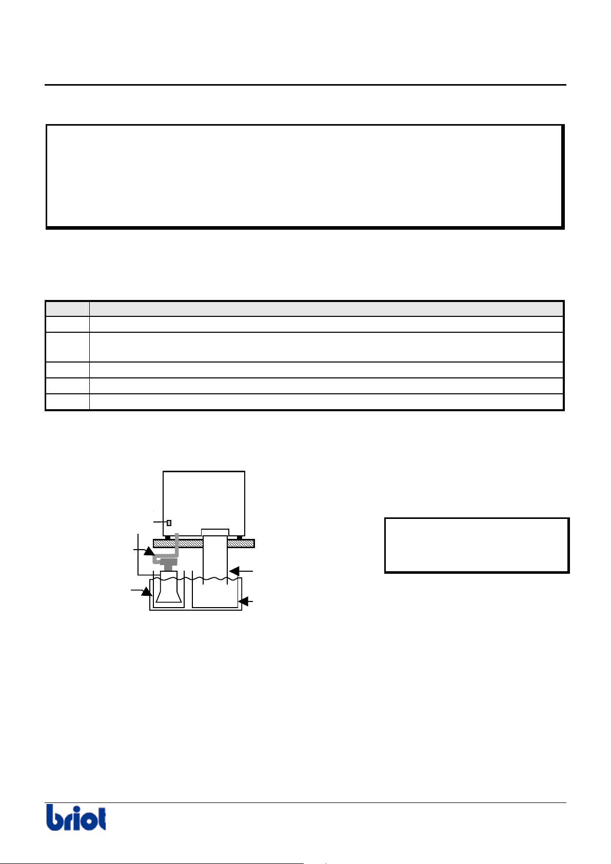
Annex A - Operation in recirculating mode
Installing the recirculating system
WARNING
Only pumps that comply with the relevant safety requirements are permitted:
• 115 V/230 V: Voltage of pump outlet
• Power available for the pump: 350 W.
• Mandatory marking CE standard EN 60 335-1 and EN 60 335-2-41
• Thermal protection presence
• IP 68
PROCEDURE
Follow the steps below to install a recirculating system.
Step Action
1 Place system assembly under workbench.
2 Connect the main water supply pipe to the edger.
To do this, consult the following diagram.
3 Connect the pump to the edger, using the power supply cord.
4 Fill the recirculating tank with water 3/4 full.
5 Start the machine without a lens to prime the pump.
ILLUSTRATION
The following diagram shows the installation of your recirculating system.
Electrical connection
accordement
électrique
Water supply
Adduction
d’eau
Pump filter
Filtre
pompe
Edger
(front view)
Do not mount the joint filter on
the water supply in the case of
a recirculating system.
Water outlet
Evacuation d’eau
Decantation/filter
Décantation/filtre
Silver FC 00 511 A - 3
Page 85
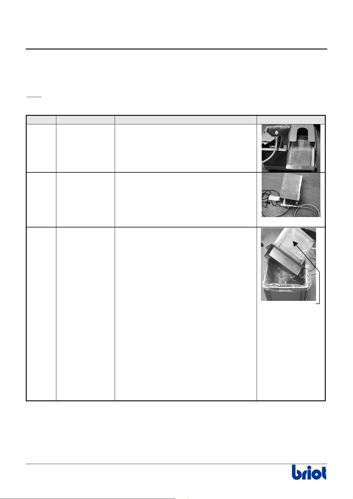
Annex A - Operation in recirculating mode
Cleaning the Pump
PROCEDURE
Cleaning the pump recirculation system can be done at different levels.
: The recirculating tank should be cleaned periodically, with more frequency if the workload
Note
increases.
Level Condition Action Illustration
1 Everyday
cleaning
2
3 Low water flow
• Low
• Pump
even after
intervention on
1st and 2nd level
water flow
floats in
the tank
Slide out the drawer filter and clean it.
Take out the pump tank with the pump.
• Brush the filter (sides) of the pump
tank
• Put back the assembly on the main
tank.
• Add water if necessary.
Complete cleaning of the system :
• Empty the main tank
(See paragraph Emptying Main Tank
below).
• Take out the pump tank with
the pump.
• Remove, empty and clean the
decantation tank with a brush.
The mud will be dumped in the
main tank.
• Remove and throw away the plastic
bag of the main tank.
• Put back all the parts of the system
after installing a new plastic bag in
the main tank
• Fill the tank up to 6 to 7 mm
(2-3 inches) from the top of
the main tank.
• Make an void cycle (no lens)
to prime the pump and edger.
Empty the
decantation
tank in a
plastic bag
A - 4 Silver FC 00 511
Page 86
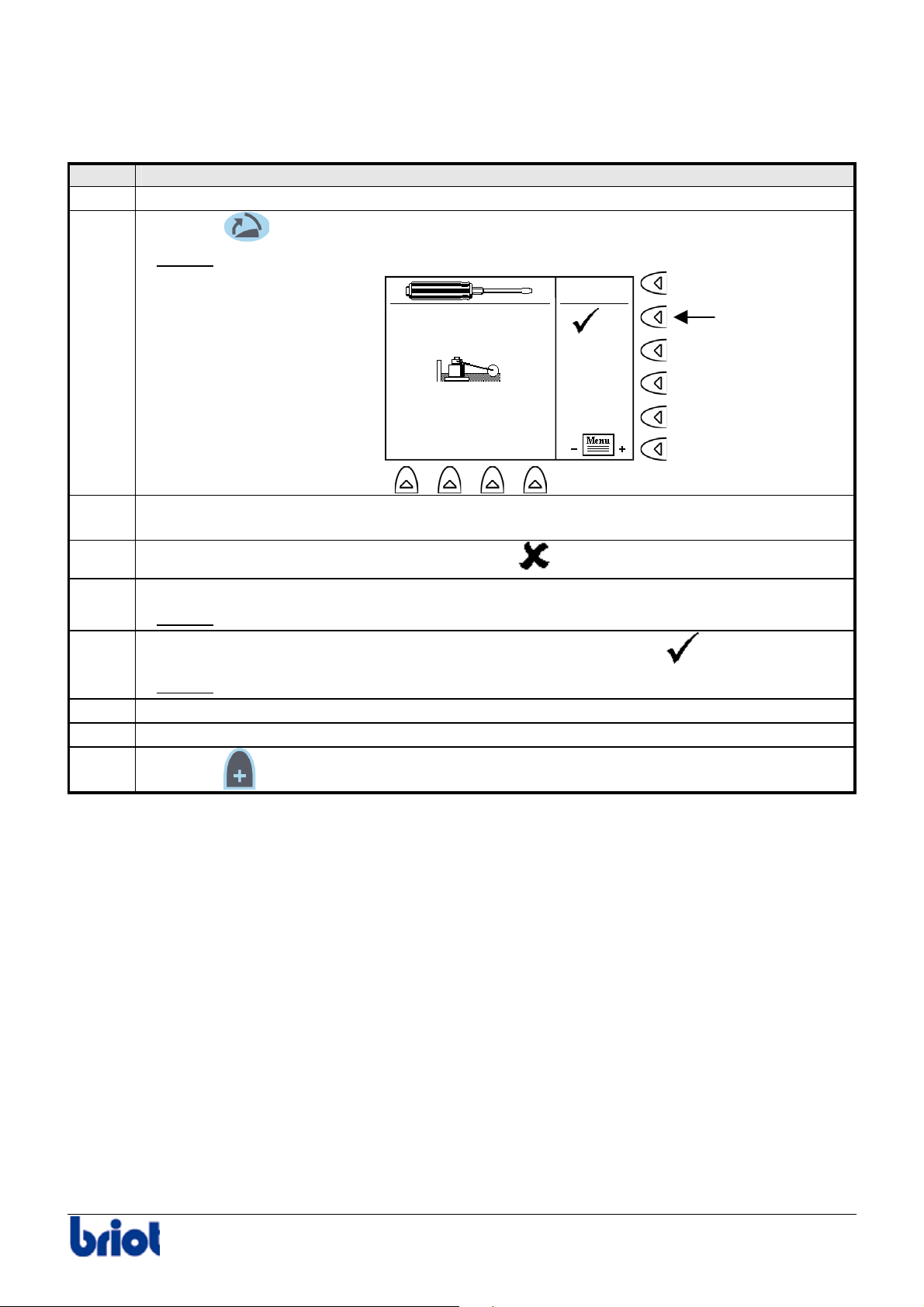
Annex A - Operation in recirculating mode
EMPTYING MAIN TANK
Follow the steps below to empty the main tank.
Step Action
1 Switch off the edger.
2
Press the
key while you switch on the edger.
Result:
the following screen is displayed.
Fct1
3 Disconnect the main water supply pipe (edger side) and connect the dump pipe
to the main drain (bucket, sink, sewer, etc.).
4
Start the pump: press the Fct1 key and display
.
5 Turn on the faucet of the dump pipe.
Result: the main tank dumping starts.
6
When the emptying is finished, press the Fct1 key and display
.
Result: the pump stops.
7 Turn off the dump pipe faucet.
8 Re-connect the water supply pipe to the edger.
9
Press the
key to reboot the machine.
Silver FC 00 511 A - 5
Page 87

Page 88

Annex B Use of the internal memory
Page 89

Page 90
Annex B - Use of the internal memory
Introduction
ICONS
The following icons are used when operating with the internal memory.
Function Selection Description
Fct7
Fct8
MEMORY CAPACITY
• You can save up to 156 jobs.
• The memory is made up of 4 blocks of 39 jobs each.
When there are 117 jobs in the memory (3 blocks filled up), the message “Memory full” is
displayed and tells the operator there are only 39 places (1 block) left for 39 jobs. After these 117
saved jobs, the system counts down the number of places remaining and displays the number of
jobs that the user will be able to save (39, 38,37, etc.). When the last 39 jobs are saved, it totally
deletes block n°1, i.e. the first 39 jobs. The last block replaces the first.
To call a shape saved in memory
The current job will not be saved.
The current job will be saved.
Caution! The job is saved once you call or create another one.
Silver FC 00 511 B-3
Page 91

Annex B - Use of the internal memory
Using the internal memory
CONFIGURATION
The configuration of your edger is performed by a technician. For any changes to the
configuration or any information about this, please contact your supplier.
CREATING AND SAVING A JOB
Follow the steps below to create and save a job.
Step Action
1
Press one or several times the Fct0 to access the tracing mode.
Fct 0
2
3
4
5
6
7
Fct 8Fct 7
Enter a job number using the keyboard or the barcode reader.
Select the job origin using the key Fct7:
•
Or
•
.
The screen above shows that the job will be traced by the Scanform™.
Select the destination of this new job: press the key Fct8 and select
Result:
Your job will be saved in memory.
Caution! Your current job will be saved when you call or create a new job.
Enter the tracing parameters and
trace your job.
Refer to the section Creating a job.
Access the lay-out/blocking screen and
enter the job data (distance, height etc.).
Refer to the section Lay-out.
Access the edging screen and
enter the job data (lens type, bevel, etc.)
Refer to the section Edging.
.
B-4
Silver FC 00 511
Page 92
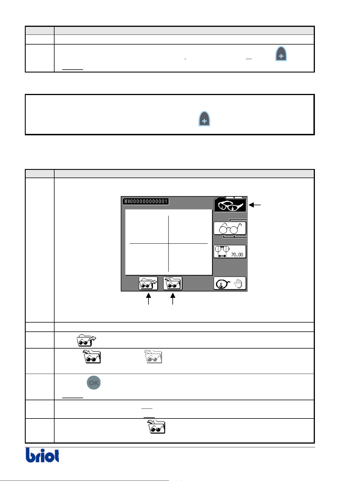
Annex B - Use of the internal memory
Step Action
8
Access the tracing screen again by pressing the key Fct0.
9
Create a new job using the digital keyboard,
the barcode reader or the key .
Result:
the job is now saved in memory with the specified number.
ADVICE
• Carefully note the job number you have just created. It corresponds to your new job
number. You will be able to recall it easily in the future.
• If you wish to save the last job of the day, press the
key in tracing mode before
switching off the machine.
CALL UP A JOB SAVED IN MEMORY
Follow the steps below to call a job saved in memory.
Step Action
1
Press one or several times the Fct0 to access the tracing mode.
Fct 0
2
3
4
5
6
7
Fct 8Fct 7
Enter the job number to recall using the keyboard or the barcode reader.
Select
Activate
using the key Fct7.
or deactivate the storing function using Fct8, as you require.
Caution! Your current job will be saved when you call or create a new job.
Press the
Result:
the job saved in memory appears on the screen.
Move to the lay-out/blocking and
Refer to the sections Lay-out and
If you selected the save option
key to call the job.
edging screens in order to block and edge the lens.
Edging.
, repeat steps 8 and 9 of the procedure Creating
and Saving a Job as before.
Silver FC 00 511 B-5
Page 93

Annex B - Use of the internal memory
Note
To call a job, you can also use the barcode reader.
Proceed as follows:
• Read the job barcodes using the mini-scanner.
Result:
The shape you have called appears.
B-6
Silver FC 00 511
Page 94

Annex C Connection to the OMA network
Page 95

Page 96
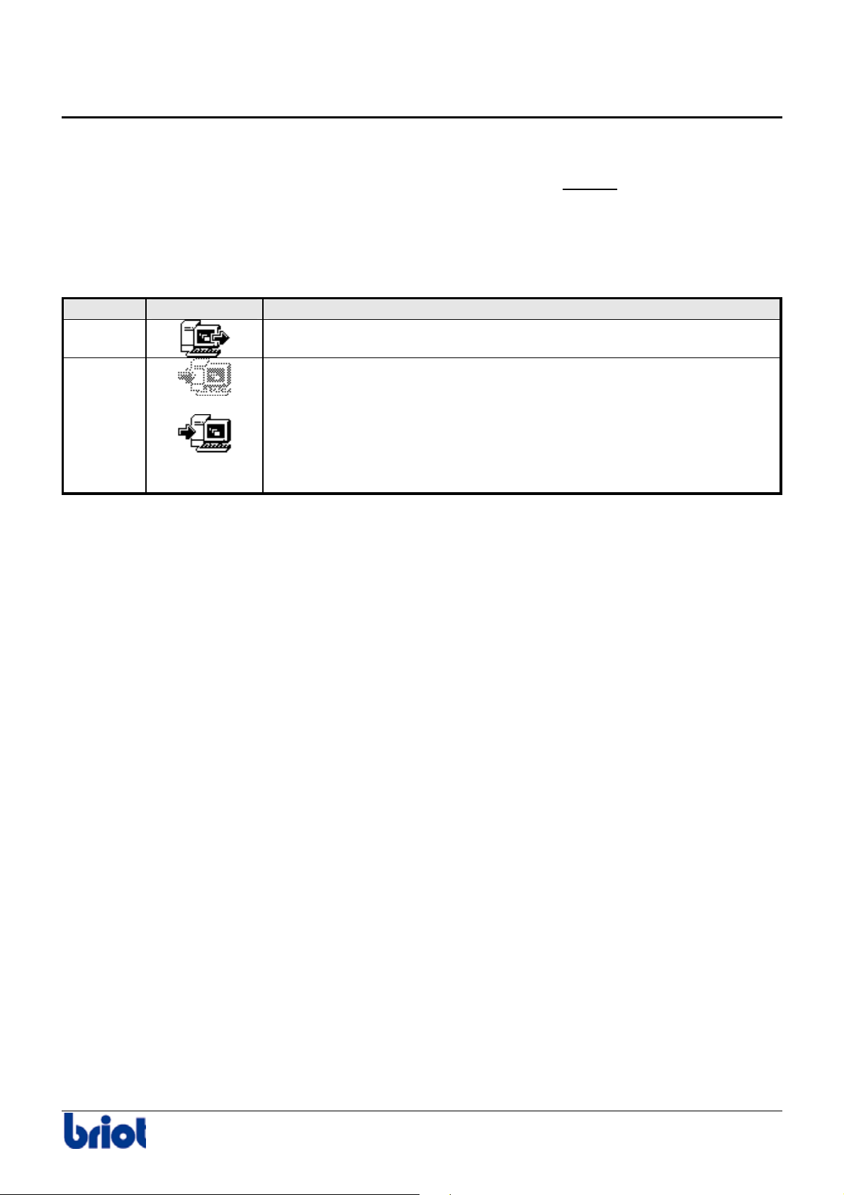
Annex C - Connection to the OMA network
Introduction
WARNING
Please note that you should always run the BOA or Sylab programs AFTER having switched on
the machine.
ICONS
The following icons are used when your machine is connected to a server .
Function Selection Description
Fct7
Fct8
To call a shape saved on the server.
The current job will not be saved on the server.
The current job will be saved on the server.
Caution ! The job is saved once you call or create another one.
Silver FC 00 511 C- 3
Page 97
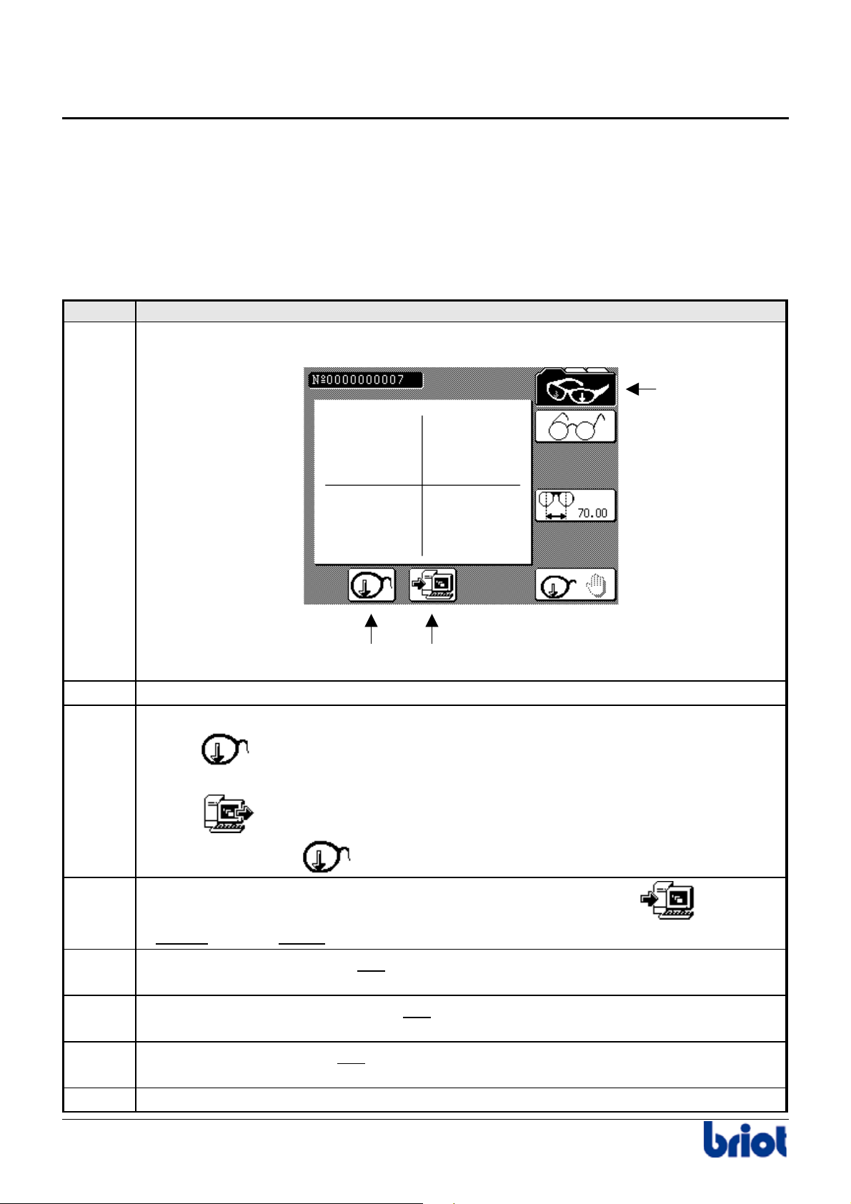
Annex C - Connection to the OMA network
Connection to the OMA network
CONFIGURATION
The configuration of your edger is performed by a technician. For any changes to the
configuration or any information about this, please contact your supplier.
CREATING AND SAVING A JOB
Follow the steps below to create and save a job on the server.
Step Action
1
Press one or several times the Fct0 to access to tracing mode.
Fct 0
2
3
4
5
6
7
8
Fct 8Fct 7
Enter a job number using the keyboard or the barcode reader.
Select the job origin using the key Fct7:
•
Or
•
Here, the Scanform™
.
Select the destination of this new job: press the key Fct8 and select
Result:
Enter the tracing parameters and
Your job will be saved on the server.
trace your job.
Refer to the section Creating a job.
Access the lay-out/blocking screen and
enter the job data (distance, height etc.).
Refer to the section Lay-out.
Access the edging screen and
enter the job data (lens type, bevel, etc.)
Refer to the section Edging.
Access the tracing screen again by pressing the key Fct0.
.
C- 4 Silver FC 00 511
Page 98
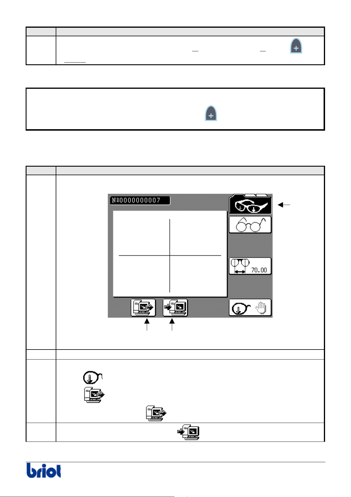
Annex C - Connection to the OMA network
Step Action
9
Create a new job using the digital keyboard or
the barcode reader or the key .
Result:
the job is now saved on the server with the specified number.
ADVICE
• Carefully note the job number you have just created. It corresponds to your new job
number. You will be able to recall it easily in the future.
• If you wish to save the last job of the day, press the
key in tracing mode before
switching off the machine.
CALL UP A JOB SAVED ON THE SERVER
Follow the steps below to call a job saved on the server.
Step Action
1
Press one or several times the Fct0 to access to tracing mode.
Fct 0
2
3
4
Fct 8Fct 7
Enter the job number to recall using the keyboard or the barcode reader.
Select the job origin using the key Fct7:
•
•
Here, the origin is the server
If necessary, select the job destination
Silver FC 00 511 C- 5
.
using the key Fct8.
Page 99
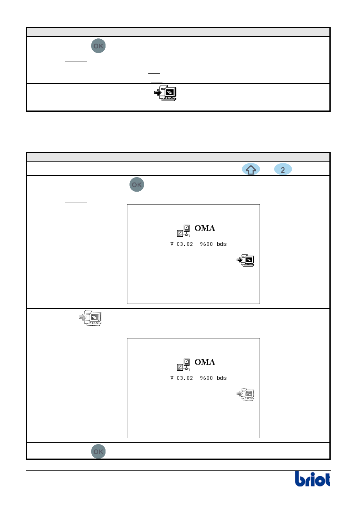
Annex C - Connection to the OMA network
Step Action
5
Press the
key to call the job.
the job saved on the server appears on the screen.
edging screens in order to block and edge the lens.
Edging.
6
Result:
Move to the lay-out/blocking and
Refer to the sections Lay-out and
7
If you selected the save option
, repeat steps 8 and 9 of the procedure Creating
and Saving a Job as before.
JOB UPLOADING FUNCTION DISABLED
You can prevent jobs from being automatically uploaded to a server.
To suppress this function, proceed as follows.
Step Action
1
When you are in tracing mode, press simultaneously the and keys.
2
Press twice on the key
Result:
the following screen is displayed.
.
3
Select
Result:
using the function Fct3.
job uploading is no longer authorized. The following screen is displayed:
4
Press the
key to return to the tracing screen
C- 6 Silver FC 00 511
Page 100

Annex D Use of the barcode reader
 Loading...