

Page 1
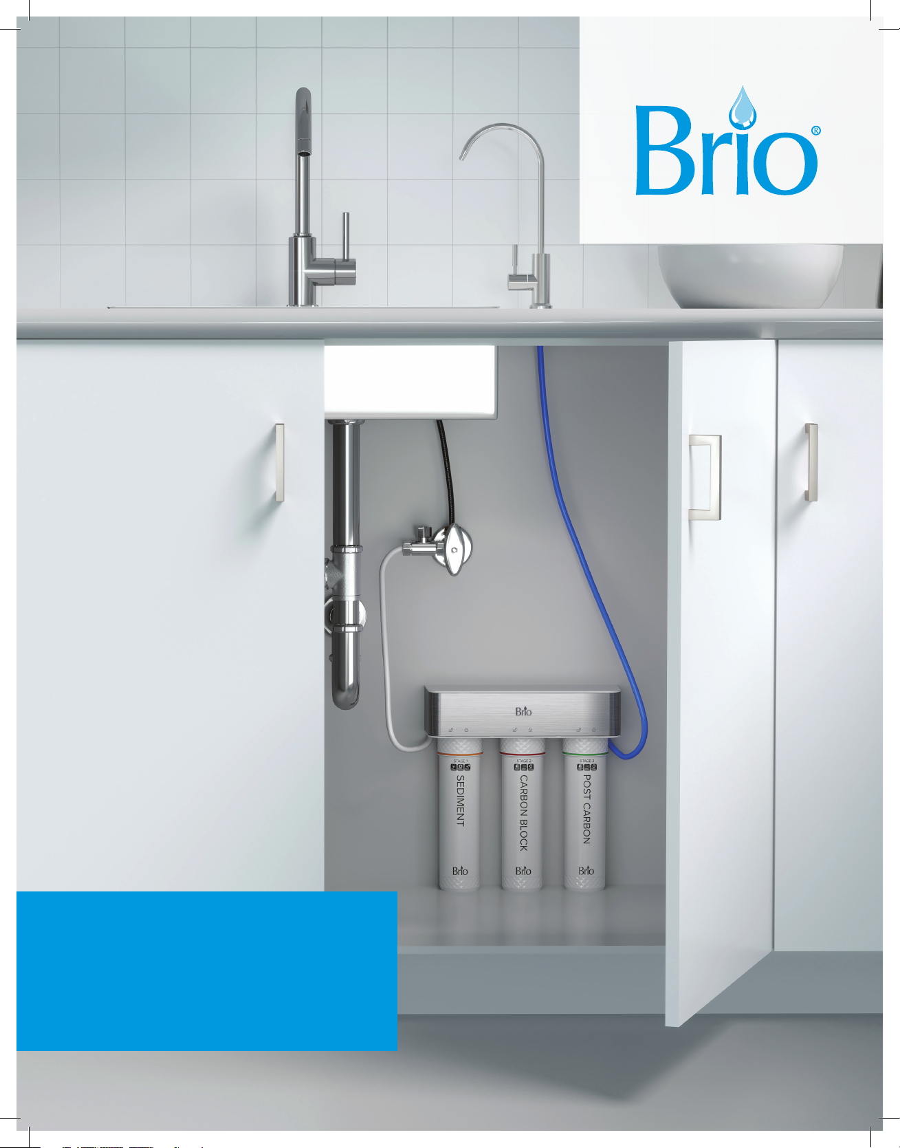
3-Stage Under Sink
Filtration System
Instruction Manual
Model No.: FUS300R
Page 2

Table of Contents
Safety Information � � � � � � � � � � � � � � � � � � � � � � � � � � � � � � � � � � � � � � � � � � � � � � � � � � � � � � � � � � � � � � � � � � � 3
Intended Use ������������������������������������������������������������������������3
Package Contents � � � � � � � � � � � � � � � � � � � � � � � � � � � � � � � � � � � � � � � � � � � � � � � � � � � � � � � � � � � � � � � � � � �4
Materials Needed � � � � � � � � � � � � � � � � � � � � � � � � � � � � � � � � � � � � � � � � � � � � � � � � � � � � � � � � � � � � � � � � � � �5
Installation Overview � � � � � � � � � � � � � � � � � � � � � � � � � � � � � � � � � � � � � � � � � � � � � � � � � � � � � � � � � � � � � � � � �5
Installation ��������������������������������������������������������������������������6
Connect to the Cold Water Supply . . . . . . . . . . . . . . . . . . . . . . . . . . . . . . . . . . . . . . . . . . . . . . . . . . . . . . . 6
Install the Filtration Faucet . . . . . . . . . . . . . . . . . . . . . . . . . . . . . . . . . . . . . . . . . . . . . . . . . . . . . . . . . . . . . . 7
Make the Connections . . . . . . . . . . . . . . . . . . . . . . . . . . . . . . . . . . . . . . . . . . . . . . . . . . . . . . . . . . . . . . . . . 7
Install the Battery . . . . . . . . . . . . . . . . . . . . . . . . . . . . . . . . . . . . . . . . . . . . . . . . . . . . . . . . . . . . . . . . . . . . . . 8
Flush the System . . . . . . . . . . . . . . . . . . . . . . . . . . . . . . . . . . . . . . . . . . . . . . . . . . . . . . . . . . . . . . . . . . . . . . 8
Operation ���������������������������������������������������������������������������9
Operational Specifications . . . . . . . . . . . . . . . . . . . . . . . . . . . . . . . . . . . . . . . . . . . . . . . . . . . . . . . . . . . . . . 9
Indicator Panel Description . . . . . . . . . . . . . . . . . . . . . . . . . . . . . . . . . . . . . . . . . . . . . . . . . . . . . . . . . . . . . 9
Maintenance �����������������������������������������������������������������������10
Replace the Filters . . . . . . . . . . . . . . . . . . . . . . . . . . . . . . . . . . . . . . . . . . . . . . . . . . . . . . . . . . . . . . . . . . . . 10
Filter Specifications . . . . . . . . . . . . . . . . . . . . . . . . . . . . . . . . . . . . . . . . . . . . . . . . . . . . . . . . . . . . . . . . . . . . 11
Replace the Battery . . . . . . . . . . . . . . . . . . . . . . . . . . . . . . . . . . . . . . . . . . . . . . . . . . . . . . . . . . . . . . . . . . . . 11
Troubleshooting ��������������������������������������������������������������������12
Warranty ���������������������������������������������������������������������������13
2
Page 3

Safety Information
WARNING: To reduce risk of injury and property damage, you must read this entire guide before assembling,
installing, and operating the filtration system.
• Installation needs to comply with state and local laws and regulations.
• Product must be installed indoors. Do NOT use outdoors.
• Use only the hoses supplied with the unit; old hoses should not be reused.
• Keep the product in a dry place away from direct sunlight.
• Do NOT store in or expose the product to temperatures lower than 32 °F (0 °C). The ideal temperature
range is 39–100 °F (4–38 °C).
• Keep the product away from heat sources or open flames.
• Do NOT place unit near strong magnetic devices, as this may cause the filter life indicator to fail.
• Do NOT immerse the product in water or other liquids.
• Do NOT use with water that is microbiologically unsafe or of unknown quality without adequate disinfection
before or after the product.
• The product is suitable for municipal tap water. The best working pressure for this product is 30–100 psi.
If the water pressure is unstable, install a pressure reducing valve at the water inlet for the product.
• The design life of the product is 5 years. Replace the whole unit when the life expires.
• To ensure the health of you and your family, regularly replace the filters.
• In case of a water outage or pipeline maintenance, close the water inlet valve; otherwise, the service life
of the filter may be aected. When re-supplying water, turn on the faucet and allow the water to run for
10minutes before dispensing.
• The flow rate will decrease when the ambient temperature is low, which is an inherent characteristic of
the filter.
• Service should be performed only by a certified technician. Never remove any parts to avoid leakage
or damage.
Intended Use
This filtration system is intended to be used in household and similar applications such as:
• Sta kitchen areas in shops, oces, and other working environments
• Farm houses
• Hotels, motels, and other residential type environments
This system is not intended for use by persons (including children) with reduced physical, sensory or mental
capabilities, or lack of experience and knowledge, unless they have been given supervision or instruction
concerning use of the system by a person responsible for their safety.
3
Page 4
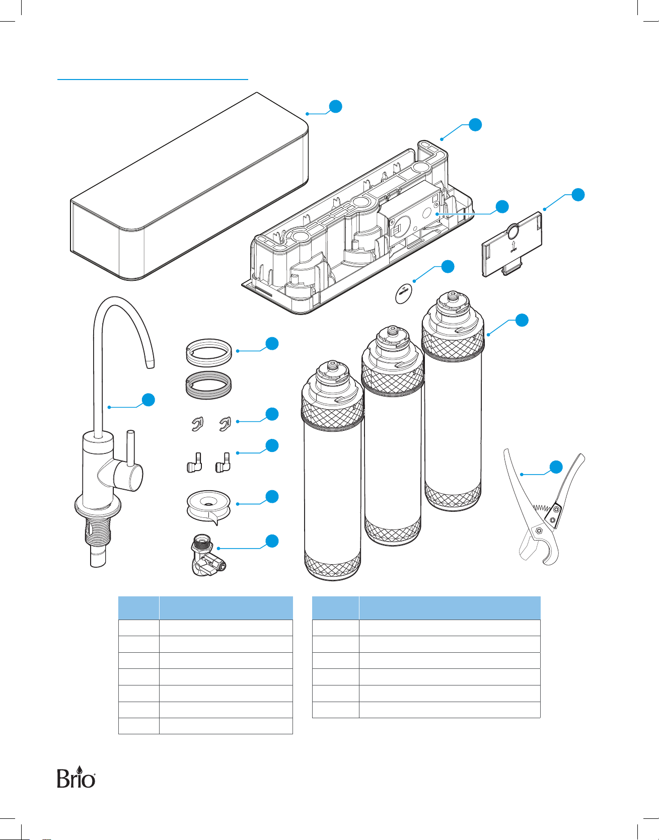
Package Contents
A
C
B
D
E
F
H
G
L
I
J
K
Part Description Part Description
A Top cover H PE tubing, 1/4 in. (qty. 2)
B Transparent cover plate I Quick coupling, 1/4 in. (qty. 2)
C Filter housing J Seal tape
D Indicator panel K Feed water adapter
E Battery CR2450 L Locking clips (qty. 2)
F Filters (qty. 3) M Tube cutter
G Filtration faucet
M
4
Page 5
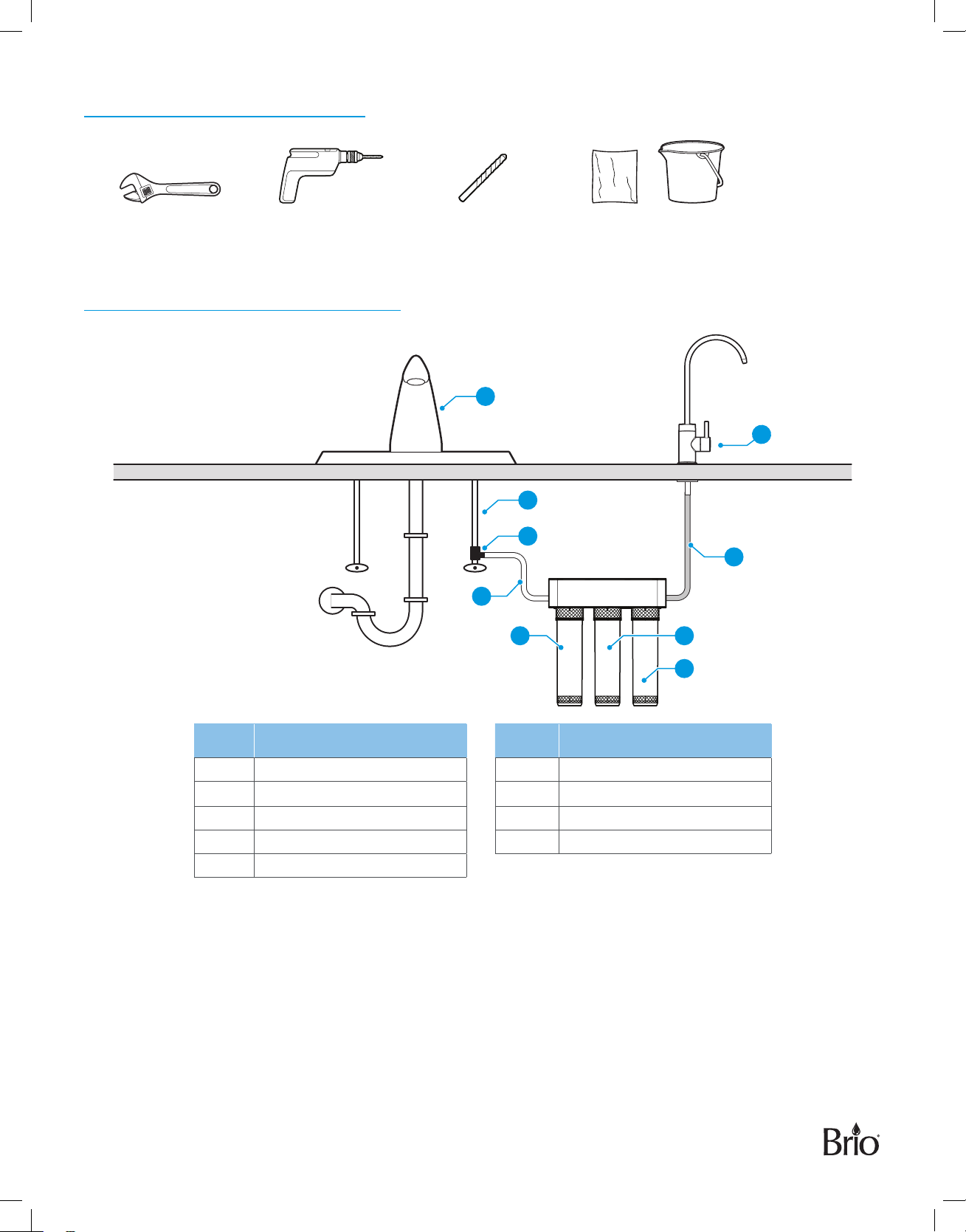
Materials Needed
Adjustable wrench Power drill Drill bit (1 in.) Towel or bucket
Installation Overview
8
4
G
5
6
1
2
3
Part Description Part Description
1 Sediment filter (stage 1) 6 Inlet water tubing (white)
2 Carbon block filter (stage 2) 7 Outlet water tubing (blue)
3 Post carbon filter (stage 3) 8 Existing faucet
4 Cold water supply G Filtration faucet
5 Feed water adapter
7
5
Page 6
Installation
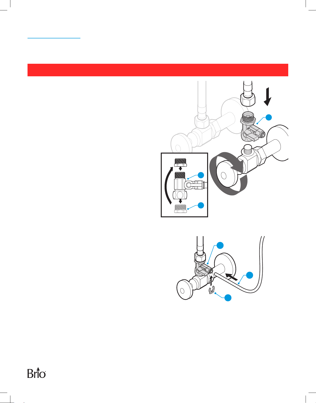
1� Connect to the Cold Water Supply
CAUTION: DO NOT CONNECT THIS WATER LINE TO A HOT WATER SUPPLY LINE. The water supply to the
unit MUST be from the COLD WATER LINE. Using HOT WATER will severely damage the filters.
A� Turn o the cold water supply valve.
B� Turn on the existing faucet to release the water
pressure.
NOTE: Make sure the water has completely
drained before proceeding to the next step.
Use a towel or bucket to catch any excess
water.
C� Using an adjustable wrench, disconnect the cold
water pipe from the cold water supply valve.
NOTE: If the cold water pipe is 1/2in., unscrew the
converter(9) from the A end of the feed
water adapter (K), and then screw it on the
B end of the feed water adapter(K).
D� Tighten the converter (9).
B
K
K
E� Twist the feed water adapter(K) onto the cold
water supply valve and tighten it using an
adjustable wrench.
F� Twist the cold water pipe to the top of the feed
water adapter(K) and tighten it using an adjustable
wrench.
G� Insert the one end of the white inlet water
tubing(6) into the quick connector on the feed
water adapter(K) and pop in the lock clip (L) on
the fitting.
H� Gently tug on the white inlet water tubing(6) to
ensure a secure connection with the fitting.
A
9
K
6
L
6
Page 7
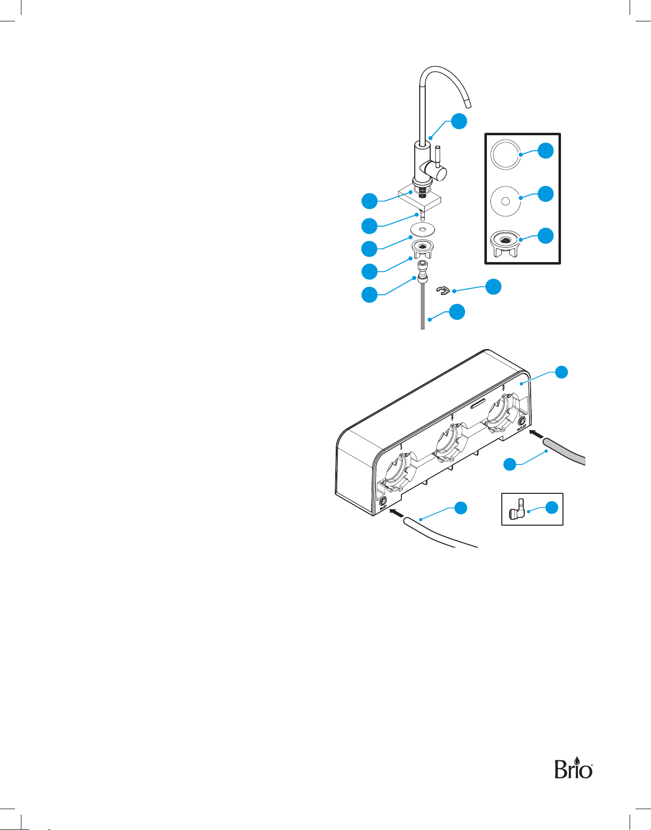
2� Install the Filtration Faucet
NOTE: If there is no hole in the sink or countertop
for the filtration faucet stem, drill a 1in. hole
or use the hole for the soap dispenser.
A� Insert the faucet stem(10) through the O-ring (11)
and into the hole in the sink or countertop.
B� Under the sink, slide the rubber washer(12) onto
the faucet stem(10). Slide on the locking nut (13)
and hand tighten to ensure the faucetis secured
to the countertop or sink.
11
G
11
12
C� Insert one end of the connector (14) onto the base
of the faucet stem (10) and pop a lock clip (L)
around the collet.
D� Insert one end of the blue outlet water tubing (6)
into the other end of the connector (14) and pop
a lock clip (L) around the collet. Gently tug on the
blue tubing to ensure a secure connection.
3� Make the Connections
A� Insert the other end of the white inlet water
tubing(6) into the water inlet end of the filter
housing (C). If needed to accommodate the angle,
use the quick coupling (I) provided.
B� Insert the other end of the blue outlet water
tubing(7) into the water outlet end of the filter
housing (C). If needed to accommodate the angle,
use the quick coupling (I) provided.
10
12
13
14
13
L
6
C
7
6
I
7
Page 8
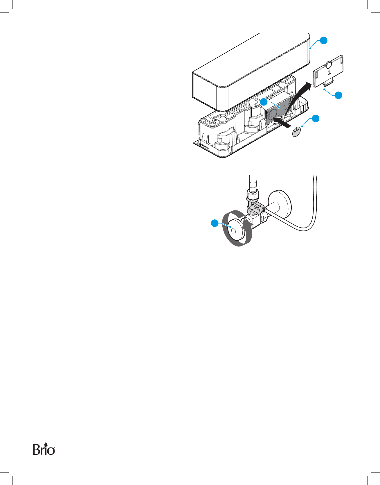
4� Install the Battery
A� Lift o the top cover (A) of the filter housing and
remove the transparent cover plate(B).
B� Insert the battery (E) into the indicator panel(D).
The positive side of the battery should be facing
outward.
C� Reassemble the transparent cover plate(B) and
the top cover(A).
5� Flush the System
CAUTION: Do NOT drink water from your new
system until you have completed the
suggested flushing process.
A� Turn on the filtration faucet first, and then turn on
the cold water supply valve(3).
B� Allow the water to run for 10minutes.
A
B
D
E
3
NOTE: Since the filter material contains granular
activated carbon, it is normal that the water
is black when dispensing for the first time.
C� Turn o the filtration faucet and wait for one hour.
While waiting, monitor the system for any leaks.
D� Turn on the filtration faucet again and allow the
water to run for another 10minutes to completely
flush the system.
E� Check again for leaks. If there are no leaks, the
filtration faucet is ready for use.
8
Page 9
Operation
Operational Specifications
Operating Temperature
Operating Pressure
pH Parameters
Iron
TDS (Total Dissolved Solids)
Turbidity
Minimum 39 °F (4 °C) Maximum 100 °F (38 °C)
Minimum 30 psi (0.20 MPa) Maximum 100 psi (0.69 MPa)
Minimum 2 Maximum 11
Maximum 0.2 ppm
< 1800 ppm
< 5 NTU
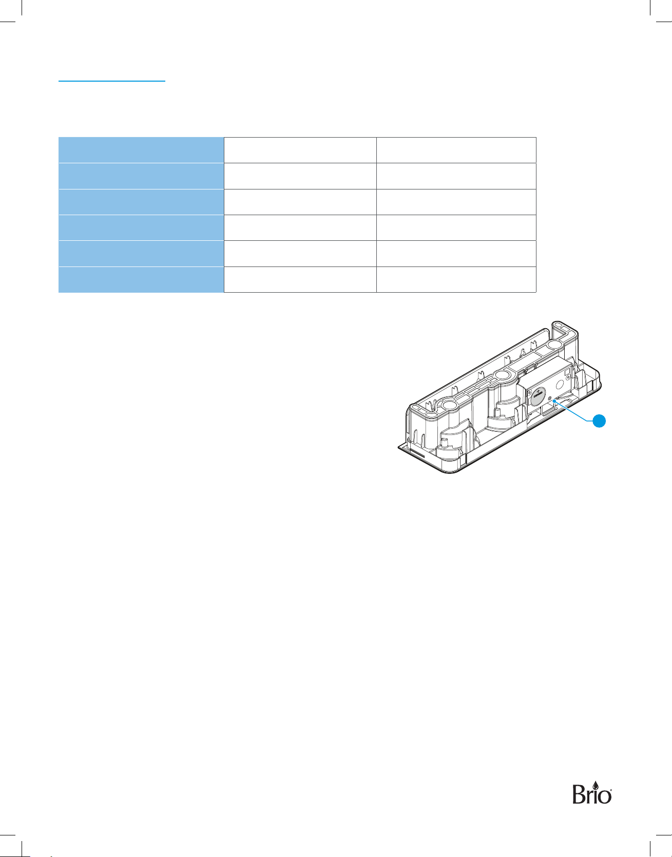
Indicator Panel Description
The indicator panel is used to indicate filter life.
• The red LED (15) on the indicator panel flashes to indicate
the filter life has expired.
• If the faucet is turned on while the red LED(15) is flashing,
the unit will beep as a reminder. The unit will stop beeping
after turning o the faucet.
15
• If the faucet is on and runs continuously for >30minutes,
the unit will beep as a reminder to turn the faucet o. The
unit will stop beeping after turning o the faucet.
9
Page 10
Maintenance
Replace the Filters
Replace the filters every 6 to 12 months or 950gallons (3600liters), whichever comes first. The red LED light on
the indicator panel flashes to indicate the filter life has expired.
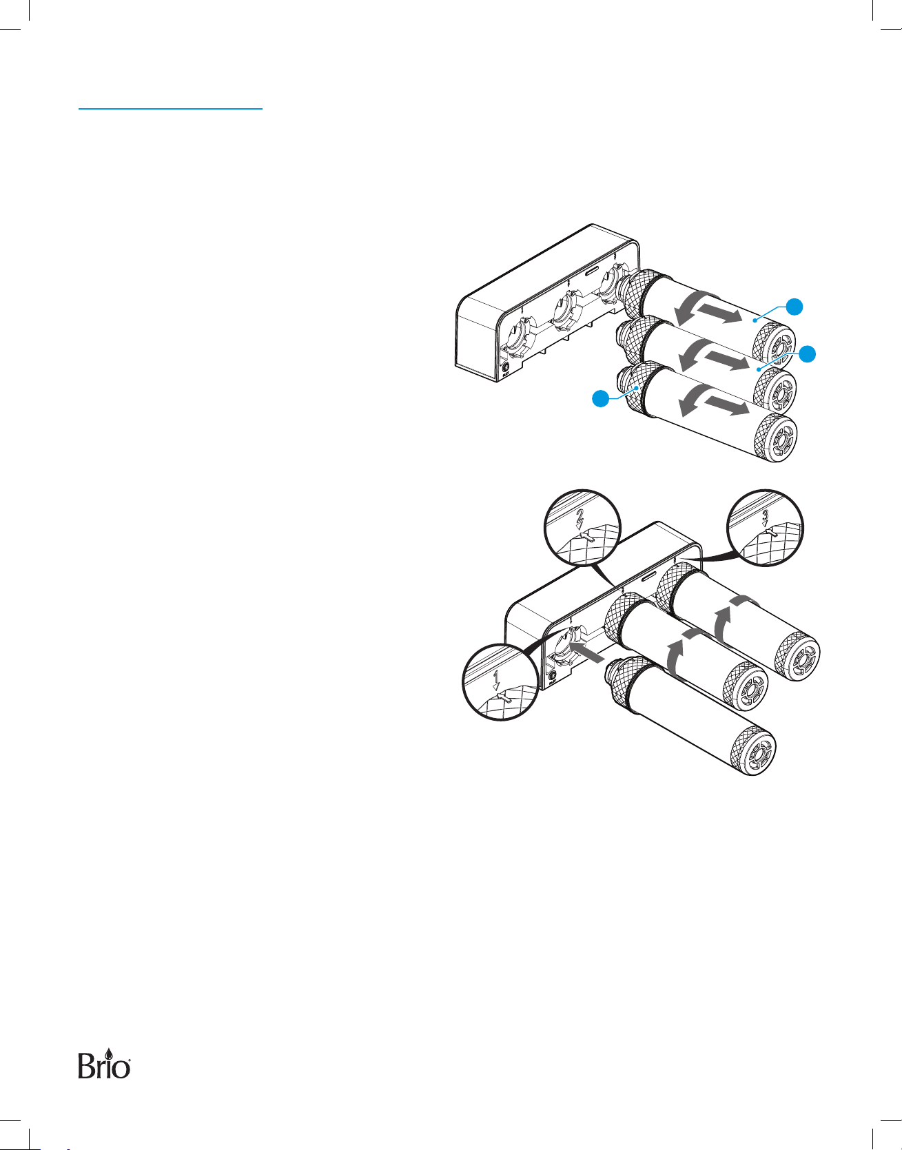
1� Turn o the cold water supply valve.
2� Turn on the filtration faucet to drain the
system.
NOTE: Remove the filters sequentially; stage1
sediment filter (1) first, then stage 2
pre carbon filter(2), and then stage 3
ultrafiltration filter (3).
3
2
3� Remove the filter by rotating counterclockwise
90° and then pulling downwards.
NOTE: Install the new filters in reverse
sequence; stage 3 ultrafiltration filter,
stage 2 pre carbon filter, and then
stage 1 sediment filter.
4� Insert the new filter into the housing, being
sure to align grooves. Firmly push filter in,
then rotate clockwise 90°. The arrow on the
filter should align with the ∆ mark on the filter
housing as shown, and the filter should be
securely locked in place.
5� To ensure normal operation, replace the
battery every time you replace the filter.
See “Replace the Battery” on page 11.
6� Flush the new filters before use.
See “5. Flush the System” on page 8.
1
10
Page 11
Filter Specifications
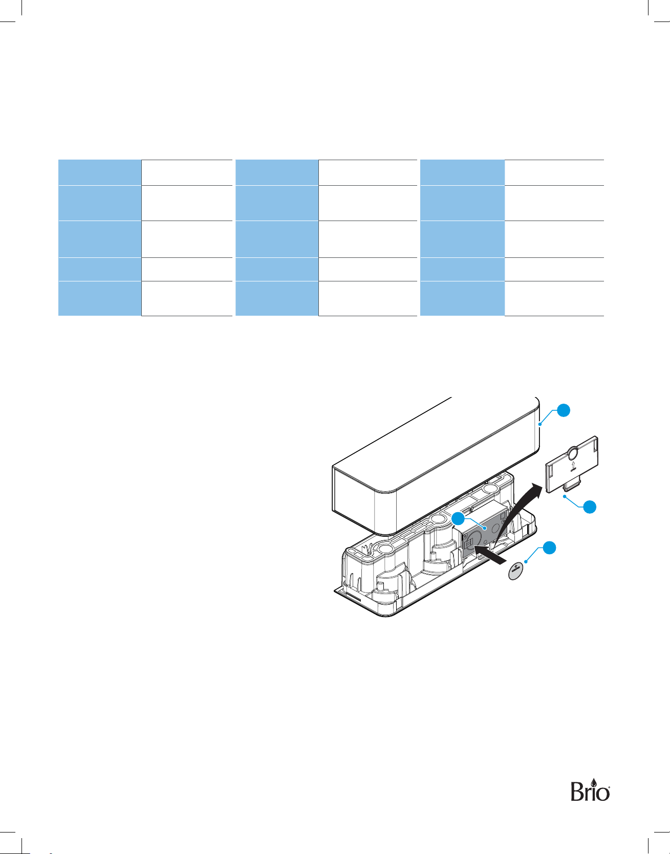
Always use proper replacement filter cartridges. Refer to the table below for filter replacement part numbers and
specifications.
Stage 1 – Sediment Filter Stage 2 – Carbon Block Filter Stage 3 - Post Carbon Filter
(Sediment, dirt, and rust removal) (Particles as small as 0.5 microns (Residual taste and odor removal)
removal, including lead)
Part Number
Replacement
Cycle
Filter
Capacity
Flow Rate
Suggested
PSI
RPFUSPP5M
3–6 Months
950 Gallons
(3600 Liters)
0.5 GPM (2LPM)
30–100 PSI
Part Number
Replacement
Cycle
Filter
Capacity
Flow Rate
Suggested
PSI
RPFUSCTO5MS2
3–6 Months
950 Gallons
(3600 Liters)
0.5 GPM (2LPM)
30–100 PSI
Part Number
Replacement
Cycle
Filter
Capacity
Flow Rate
Suggested
PSI
RPFUSGAC5MS3
3–6 Months
950 Gallons
(3600 Liters)
0.5 GPM (2LPM)
30–100 PSI
Replace the Battery
To ensure normal operation of the indicator panel, replace the battery every time you replace the filter. Use only
a CR2450 battery.
1� Lift o the top cover(A) of the filter housing
and remove the transparent cover plate(B).
2� Remove and properly dispose of the
old battery(E).
A
3� Insert the new battery into the indicator
panel(D). The positive side of the battery
should be facing outward.
4� Reassemble the transparent cover plate(B)
and the top cover(A).
B
D
E
11
Page 12
Troubleshooting
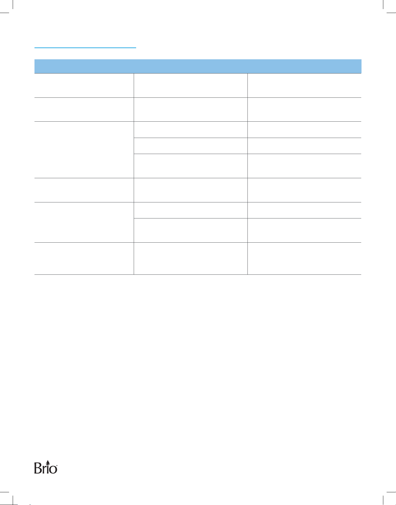
Problem Probable Cause Solution
The water has a black or dark
appearance.
The system is noisy. There is an air gap in the filtration
Water either comes out slowly
or does not come out of the
filtration faucet.
The water smells or tastes bad. The filter life may have expired. Replace the filters. See “Replace the
There are leaks in the system. The tubing is not secure. Fully insert the tubing as necessary.
Red LED is flashing on the
indicator panel, but the filter
was recently changed.
The system may not have been
properly flushed.
faucet.
The water pressure is low. Add a booster pump.
There are crimps in the tubing. Ensure the tubing is straight.
The filters are clogged. Replace the filters. See “Replace the
The feed water adapter is not
tightened.
If the water pressure is < 30 psi, the
indicator panel may not be able to
calculate the filter life properly.
Properly flush the system. See
“5. Flush the System” on page 8.
The noise will disappear after system
shutdown.
Filters” on page 10.
Filters” on page 10.
Tighten the converter and the nut on
the feed water adapter.
Increase the water pressure.
12
Page 13

Warranty
Brio (“Vendor”) warrants to the original purchaser of the Brio Water Filtration System (the “Product”), and to
no other person, that if the Product is assembled and operated in accordance with the printed instructions
accompanying it, then for a period of one (1) year from the date of purchase, all parts in the Product shall be free
from defects in material and workmanship. This Limited Warranty shall be limited to repair or replacement of
parts, which prove defective under normal use and service and which Vendor shall determine in its reasonable
discretion upon examination to be defective. To take advantage of this Limited Warranty, please follow these
steps:
1. Please retain your sales slip or invoice, as Vendor may require reasonable proof of your date of purchase.
2. Contact Vendor’s Customer Service Department using the contact information listed below.
3. Return parts to Vendor, per Vendor’s instructions, at your cost and expense.
4. Upon receipt by Vendor, Vendor shall advise you in writing whether a defect covered by this Limited Warranty
exists in any returned part and whether your claim has been approved or denied.
5. Upon Vendor’s approval of your claim, Vendor will replace such defective part without charge to you.
WHAT THIS LIMITED WARRANTY DOES NOT COVER: This Limited Warranty does not cover any failures
or operating diculties of the Product due to accident, abuse, misuse, alteration, misapplication, improper
installation or improper maintenance or service by you or any third party, or failure to perform normal and routine
maintenance on the Product, as set out in the User’s Manual. In addition, this Limited Warranty does not cover
damages to the finish, such as scratches, dents, discoloration or rust after purchase.
This Limited Warranty is the only express warranty given on the Product and is in lieu of all other express
warranties. Vendor disclaims all warranties for products that are purchased from seller other than authorized
retailers or distributors. THIS LIMITED WARRANTY RESTRICTS THE DURATION OF ANY AND ALL IMPLIED
WARRANTIES, INCLUDING WITHOUT LIMITATION, THE IMPLIED WARRANTY OF MERCHANTABILITY AND
FITNESS FOR A PARTICULAR PURPOSE TO THE ONE (1) YEAR TERM OF THIS LIMITED WARRANTY. UPON THE
EXPIRATION OF THE ONE (1) YEAR TERM OF THIS LIMITED WARRANTY, VENDOR DISCLAIMS ANY AND ALL
IMPLIED WARRANTIES, INCLUDING WITHOUT LIMITATION THE IMPLIED WARRANTIES OF MERCHANTABILITY
AND FITNESS FOR A PARTICULAR PURPOSE, THE PRODUCT BEING THUS SOLD AS-IS, WITH ALL FAULTS.
FURTHER, VENDOR SHALL HAVE NO LIABILITY WHATSOEVER TO PURCHASER OR ANY THIRD PARTY
FOR ANY SPECIAL, INDIRECT, PUNITIVE, INCIDENTAL, OR CONSEQUENTIAL DAMAGES. OTHER THAN THIS
LIMITED WARRANTY, THERE ARE NO WARRANTIES WHICH EXTEND BEYOND THE DESCRIPTION ON THE
FACE HEREOF. Vendor assumes no responsibility for any defects caused by third parties. This Limited Warranty
gives you specific legal rights, and you may have other rights which vary from state to state. State law may also
override statements in this Limited Warranty regarding the restriction on the duration of implied warranties.
Some jurisdictions do not allow exclusion or limitation of special, incidental or consequential damages, or
limitations on how long awarranty lasts, so the above exclusion and limitations may not apply to you.
13
Page 14

Call: +1 844-257-4103
©2022 Brio Water Technology, Inc.
Contact Us
 Loading...