


Smart Deadbolt
999-00451
Secure control from anywhere.
™
Installation Instructions
Simply Smart Security.
™

Installation Instructions
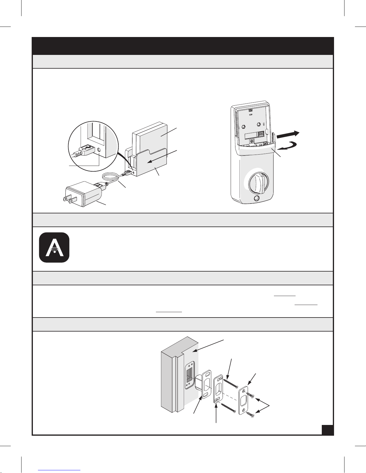
Box Contents
999-00451
Screw
Cover
Key (2)
Exterior
Assembly
Latch
Mounting Screws (2) ---------
Mounting Plate Screw (1) ------------------
Interior Housing Screw (1) -------------------------
Battery Compartment Screws (2) ----------------------
Latch & Strike Screws (4) ---------------------------
Gasket
Drive-in
Collar
Assembly
Square Corner
Face Plate
Interior
Rechargeable
Battery
Strike
Plate
Interior Mounting
Reinforcement
Plate
USB Cable
Plate
Dust Box
(Optional)
Reinforcement Screws (2) ---
Need help? Download the ARRAY™ app or visit www.arraylock.com
1
for installation videos or call 1-800-850-LOCK (5625).
Wall Adapter
Battery Charging Cradle

Tools you will need: Tools you may need:
IMPORTANT INSTALLATION NOTES. PLEASE READ:
• Remove the battery from the battery compartment and charge it in the
Charging Cradle until the LED turns green.
• The ARRAY
positioned in direct sunlight. If unable to position the lock in direct
sunlight, you may need to charge the battery more frequently. You will see
the battery status on the app.
• Do not attempt to disassemble any internal components of the lockset.
You will void the warranty.
• Do not install the battery until you’ve installed the lock and downloaded
the app. Follow the instructions in order.
• Do NOT use a power drill to install the lock. A power drill should only be
used for door preparation.
• Make sure your door is properly aligned and can be closed without
pushing, pulling or lifting the door.
lock has a built-in solar panel that will charge the battery if
™
Compatible Devices:
Note: New devices will continue to be added to enhance your experience with
the ARRAY
list of compatible devices.
lock. Please visit our website www.arraylock.com for a complete
™
2

Installation Overview
Part
Description
Key
A
Exterior Assembly
B
Cylinder
C
Tailpiece
D
Power Cable
E
Gasket
F
Latch
G
Interior Mounting Plate
H
Interior Assembly
I
Rechargeable Battery
J
Antenna Cover
K
Battery Cover
L
Tailpiece Receiver
M
Strike Plate
N
Reinforcement Plate
O
Dust Box
P
Screw Cover
Q
GASKET (F)
BATTERY COMPARTMENT
INTERIOR
ASSEMBLY (I)
MOUNTING PLATE
SCREW (BB)
RECHARGEABLE
BATTERY (J)
SCREWS (DD)
MOUNTING
SCREWS (AA)
BATTERY COVER (L)
ANTENNA
COVER (K)
SCREW COVER (Q)
INTERIOR HOUSING
SCREW (CC)
TAILPIECE
RECEIVER (M)
3
TAILPIECE (D)
POWER CABLE (E)
KEY (A)
CYLINDER (C)
EXTERIOR ASSEMBLY (B)
Part
Description
2-1/16" (52 mm) Mounting Screws (2) ---
AA
1-1/4" ( 32 mm) Mounting Plate Screw (1) ------------
BB
13/16" (20.3 mm) Interior Housing Screw (1) -----------------
CC
5/16" (7.9 mm) Battery Compartment Screws (2) -----------------
DD
3/4" (19.2 mm) Latch & Strike Screws (4) --------------------
EE
3" (76.2) Reinforcement Screws (2) ----
FF
INTERIOR MOUNTING PLATE (H)
LATCH (G)
LATCH & STRIKE SCREWS (EE)
STRIKE PLATE (N)
REINFORCEMENT PLATE (O)
REINFORCEMENT
SCREWS (FF)
DUST BOX (P)
Pre-Installation Instructions
1. Charge Battery
a. Remove the Battery Cover (L), Rechargeable
Battery (J), Battery Charging Cradle, USB Cable
and Wall Adapter. Remove the plastic tab on the
Battery (J). Slide the Battery (J) into the Charging
Cradle from the side. Charge the Battery (J) until
the LED Light turns from red to green.
Rechargeable
Battery (J)
a.
Slide
LED Light
Battery
Charging
USB Cable
Wall Adapter
Cradle
2. Watch the Installation Video
The ARRAY™ lock is compatible with either iOS or Android™ devices. Search for
“ARRAY
app is downloaded, register your lock and watch the installation video. Install your
ARRAY
www.arraylock.com/pages/installation.
Lock” at the App Store or Play Store to download the free app. Once the
™
lock (Steps 3 – 5) and then follow the instructions to add a lock or visit
™
b. Carefully remove the Antenna
Cover (K) by gently pulling the
edges outward slightly and lifting.
b.
Pull edge slightly
outward
Antenna Cover (K)
3. Prep the Door
• FITS DOORS 1-3/8" (35 mm) TO 1-3/4" (45 mm) THICK •
a. If replacing an existing deadbolt. Remove the old hardware and begin at STEP 4.
b. If installing ARRAY™ on a new door, follow the door preparation instructions on PAGE 9
and use the template provided on PAGE 10.
4. Install Latch and Strike Plate
Install Strike Plate (N) in the Door Frame
Dust box (P)
Reinforcement plate (O)
Door Jamb
3" Reinforcement Screws (FF)
Strike plate (N)
3/4" Strike Screws (EE)
4
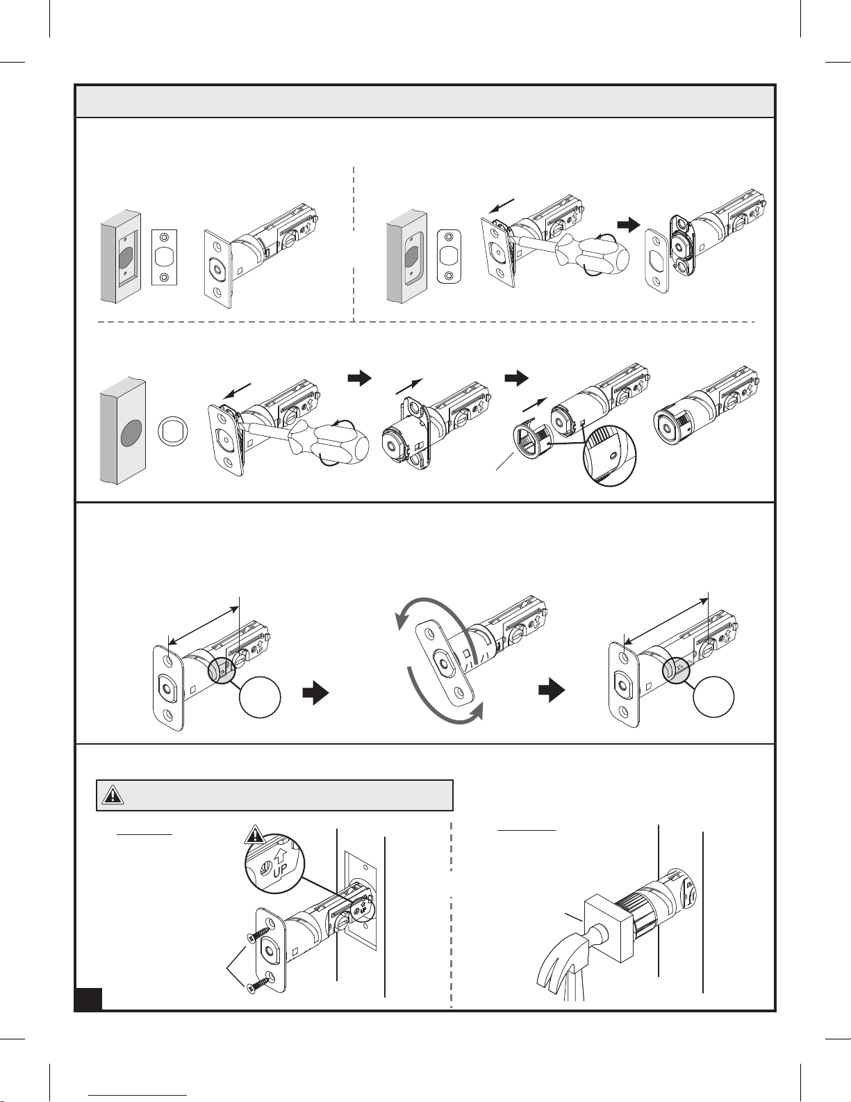
4. Install Latch and Strike Plate (Continued)
Determine the Proper Faceplate
Mortise on door edge chiseled:
a.
Square corner faceplate
b.
Round corner faceplate
a
b
OR
Door edge not chiseled:
c.
Drive-in collar option
c
Drive-in collar
Set the Latch Backset
The distance from the center of the bore hole to the edge of the door is called the backset. If the backset of your
door is 2-3/8", you don’t need to adjust the latch. The backset is preset for 2-3/8".
If the backset of your door is 2-3/4, you’ll need to adjust the latch as shown.
a.
b.
2-3/8 (60 mm)
c.
2-3/4 (70 mm)
Install the Latch
CAUTION: Be sure the latch is in the upright position.
Option 1
3/4" Latch Screws (EE)
5
2
180º
2
3
/
4
3
/
8
Option 2
OR
Wood Block
Deadbolt Installation Instructions
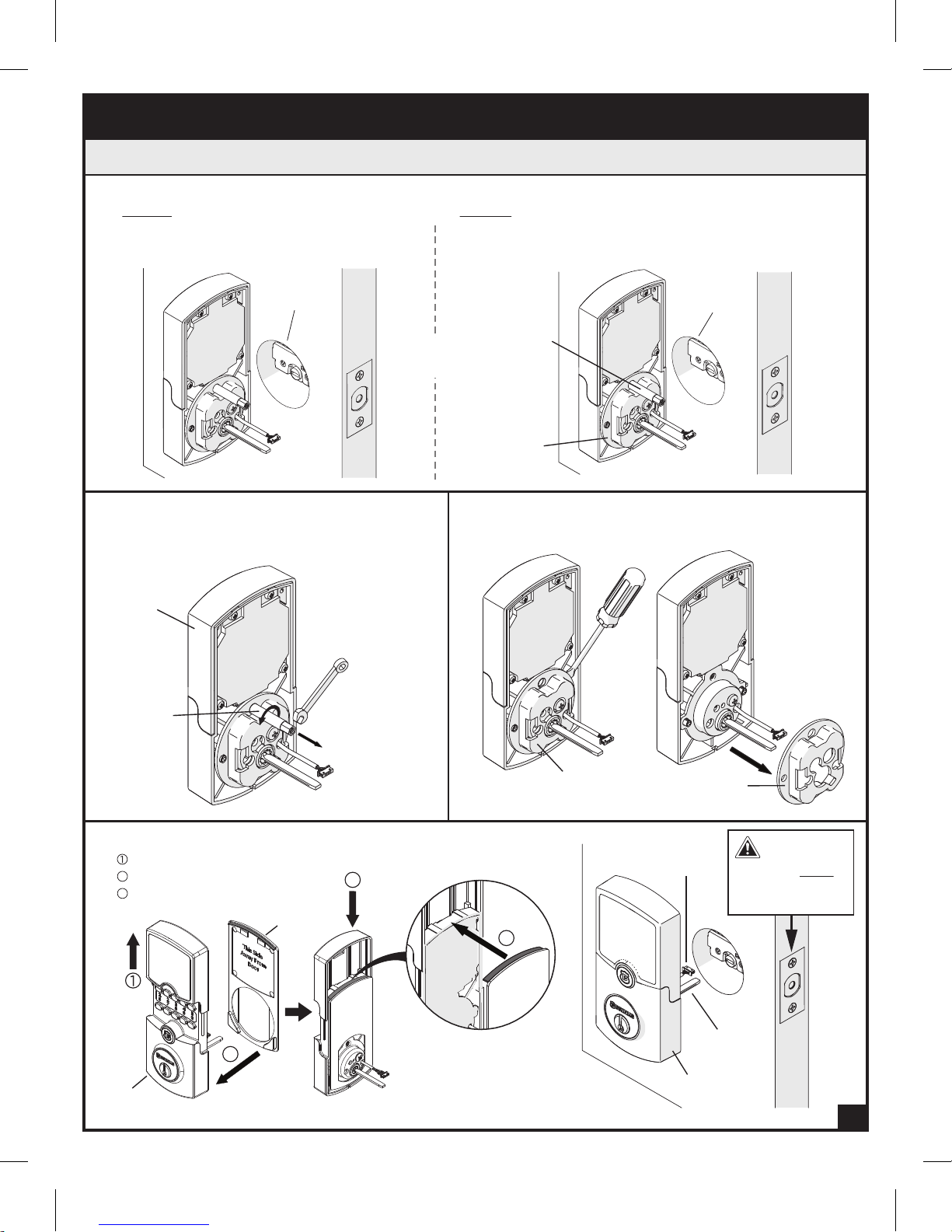
5. Install Lock Assemblies
Door Bore Hole Options
A.
Option 1
For door with bore hole 2-1/8" diameter
proceed to STEP D.
Bore Hole
2-1/8"
diameter
A.
OR
Option 2
For door with bore hole 1-1/2" diameter follow Steps B
and C for Mounting Plate Screw (BB) and Mounting Plate
removal.
Mounting
Plate
Screw (BB)
Mounting
Plate
Bore Hole
1-1/2"
diameter
A.
B.
Remove Mounting Plate Screw
Use a wrench and in a counter-clockwise motion,
remove the Mounting Plate Screw (BB).
Exterior
Assembly (B)
Mounting
Plate
Screw (BB)
Apply Gasket
D.
B.
Slide keypad cover up.
2
Apply Gasket (F).
3
Slide keypad cover down.
Gasket (F)
3
C.
Remove Mounting Plate
Use a flathead screwdriver to remove the Mounting Plate.
C.
Mounting Plate
Mounting Plate
Power
Cable (E)
IMPORTANT:
Latch bolt MUST
be in the retracted
position.
2
2
Exterior
Assembly (B)
Gasket
(F)
Gasket
(F)
Tailpiece (C)
Exterior
Assembly (B)
6

5. Install Lock Assemblies (Continued)
Power Cable (E) goes underneath the latch. Insert
E.
Tailpiece (D) horizontally.
F.
Bulged part of the Interior Mounting Plate (H)
must be toward the door.
EXTERIOR VIEW
Power
Cable (E)
E.
Tailpiece
Tailpiece (D)
Exterior
Assembly (B)
G.
Feed Power Cable (E) through Interior Mounting Plate (H) as shown. Insert Mounting Screws (AA) and
Power
Cable (E)
Mounting Plate Screw (BB) as shown and tighten.
INTERIOR VIEW
Interior Mounting
Plate (H)
Tailpiece (D)
(C)
Exterior
Assembly (B)
Mounting Plate (H)
Interior
Mounting Plate (H)
Mounting Plate
Screw (BB)
Door
F.
Interior
Power
Cable (E)
H.
Install the Power Cable (E) firmly into the Connector Port.
INTERIOR VIEW
Power
Cable (E)
H.
Connector
Port
7
Tailpiece (D)
H.
Mounting
G.
I.
Secure the Power Cable (E) onto the
Screws (AA)
Power
Cable (E)
Interior Mounting Plate (H) as shown.
Power
Cable (E)
I.
Interior
Mounting
Plate (H)

5. Install Lock Assemblies (Continued)
J.
Align the Tailpiece Receiver (M) of the Interior Assembly (I) into the Tailpiece (D).
Interior
Assembly (I)
Tailpiece Receiver (M)
J.
K.
Insert the two Battery Compartment Screws (DD)
and tighten. Insert the Interior Housing Screw (CC)
and tighten.
CAUTION:
Take care not to damage the antenna when
inserting the Battery Compartment Screws (DD).
Interior
INTERIOR VIEW
Assembly (I)
Power
Cable (E)
Tailpiece (D)
J.
Battery
Compartment
Screws (DD)
K.
Interior
Housing
Screw (CC)
L.
Re-install the Antenna Cover (K) by gently separating
both sides of the Cover (K) and snapping the Cover
(K) onto the side ridges of the Interior Assembly (I).
Apply Screw Cover (Q).
Interior
Assembly (I)
Side Ridge
L.
Pull edge
slightly outward
Antenna
Cover (K)
Screw
Cover (Q)
6. Return to the app and follow the instructions to Add a Lock
8

Door Preparation Instructions for New Doors
If installing ARRAY™ on a new door, follow the door preparation
instructions and use the template on Page 10.
Mark Door with Template
Mark the centerline for the deadbolt about 44"
a.
(1120 mm) from the floor, or about 5-1/2" (140 mm)
above the center of an existing knob or lever.
Apply the template to the door with the dotted
b.
fold line on the door edge.
Select the 2-3/8" (60 mm) or 2-3/4" (70 mm)
c.
backset and mark the center for the hole for the
deadbolt on the door face. (Most residential doors
have a 2-3/8" backset.)
Mark the center for the latch hole on the door edge
d.
according to the thickness of your door.
Drill Holes
a.
Drill a 2-1/8" (54 mm) hole on the door face from
both sides to avoid splitting wood.
b.
Drill a 1" (25.4 mm) hole in the door edge for the
latch.
c.
Insert latch into hole, mark outline of faceplate, and
chisel 1/8" (3 mm) deep or until the faceplate is
flush with the door edge.
d.
Mark latch screw holes and drill two 1/8" (3 mm)
pilot holes for the Latch Screws.
Prepare Door Jamb for Strike Plate
a.
Mark centerline on the door jamb exactly opposite
the latch hole in the door edge. Make sure that the
mark is correct so that the latch bolt will enter the
strike plate without intereference when the deadbolt
is locked.
Using the strike plate as a pattern, drill the latch and
b.
screw holes, and chisel out a mortise until the strike
plate fits flush.
a.
b.
a
5½"
140mm
44"
1120 mm
a,b c
1
2 "
1"
25.4 mm
Door Jamb Hole Dimension
A.
1-3/16" (30 mm)
B.
1-9/16" (40 mm)
C.
1" (25 mm)
Strike Plate Dimension
D.
5/32" (4 mm)
E.
2-3/4" (70 mm)
F.
1-1/8" (28 mm)
8
54 mm
B
b
c
d
F
C
E
A
D
44"
1120 mm
DOOR JAMB
9
Dust box
Door Jamb
3" Reinforcement
Screws (FF)
Strike plate
Reinforcement plate
3/4" Strike Screws (EE)
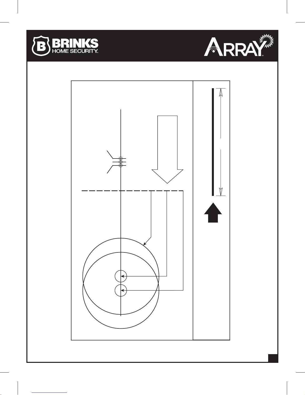
TEMPLATE
Make a 1" (25.4mm) hole at center
of door edge
Fold on dotted line and t
on door edge
45mm
1-3/4"
1-9/16"
40mm
35mm
1-3/8"
C
L
C
L
C
L
3"
Fits 2-1/8" (54mm)
cylinder hole
For backset 2-3/8" (60mm)
For backset 2-3/4" (70mm)
This line should be 3 inches. Measure it
before using this template. If the line is not 3
inches when measured, print this instruction
out, full scale on paper that is 8.5" x 11" and
measure again.
10

ARRAY™ BATTERY MANUFACTURER’S INSTRUCTIONS
WARNING:
Misusing the battery may cause it to get hot, explode, or ignite and cause injury. Follow the safety rules listed below:
•
o Do not place battery in fire or heat the battery.
o
Do not penetrate the battery with nails, strike the battery with a hammer, step on the battery, or otherwise subject it to
strong impacts or shocks.
o
Do Not Open, Crush, Heat Above 60°C (140°F), or Incinerate.
o
Do not solder directly onto the battery.
Do not disassemble or modify the battery. The battery contains safety and protection devices which, if damaged, may cause the
•
battery to generate heat, explode, or ignite.
Do not place the battery on or near fires, stoves, or other high-temperature locations.
•
o
Do not place the battery in direct sun or use or store the battery inside hot conditions.
Doing so may cause the battery to generate heat, explode, or ignite.
Immediately discontinue use of the battery if, while using, charging, or storing the battery, it emits an unusual smell, feels hot, or
•
appears abnormal in any other way.
In the event that the battery leaks and the fluid gets into one’s eye, do not rub the eye. Rinse well with water and immediately
•
seek medical care. If left untreated, the battery fluid could cause damage to the eye.
The temperature range for using the battery is -10°C to 60°C (14°F to 140°F). Use of the battery outside of this temperature
•
range may damage the performance of the battery or may reduce its life expectancy.
Do not use the battery in any device except the BRINKS HOME SECURITY ARRAY™ Smart Deadbolt.
•
FCC GENERAL STATEMENT
This device complies with part 15 of the FCC Rules. Operation is subject to the following two conditions: (1) This device may not cause harmful
interference, and (2) this device must accept any interference received, including interference that may cause undesired operation.
This equipment has been tested and found to comply with the limits for a Class B digital device, pursuant to part 15 of the FCC Rules. These limits
are designed to provide reasonable protection against harmful interference in a residential installation. This equipment generates, uses and can
radiate radio frequency energy and, if not installed and used in accordance with the instructions, may cause harmful interference to radio
communications. However, there is no guarantee that interference will not occur in a particular installation. If this equipment does cause harmful
interference to radio or television reception, which can be determined by turning the equipment o and on, the user is encouraged to try to correct
the interference by one or more of the following measures:
• Reorient or relocate the receiving antenna, or increase the separation between the equipment and receiver.
• Connect the receiver to a dierent outlet.
• Consult Hampton Products International Corporation or an experienced radio/TV technician for help.
Any changes or modifications not expressly approved by the party responsible for compliance could void the user's authority to operate the
equipment (i.e. any changes or modification that may influence the specification of radio frequency relating to the Wi-Fi
FCC ID Number: 2ANTYA2350X
is a registered trademark of Wi-Fi Alliance®.
Wi-Fi
®
WARRANTY – Full Lifetime mechanical & finish warranty and limited one-year electronics warranty.
Subject to the terms and conditions of this warranty, Hampton Products Int’l Corp. (“Hampton”) extends a full lifetime mechanical and finish warranty and a
limited one-year electronics warranty to the original residential user (“Original User”) of this product (“Product”) against defects in material and workmanship
as long as the Original User occupies the residential premises upon which the Product was originally installed. This warranty only applies to the Original User
of Product. This Warranty is not transferable. Upon pre-authorized return of defective Product to Hampton, Hampton may repair or replace the Product with
a new or refurbished product at Hampton’s sole discretion.
What is NOT covered: The following costs, expenses and damages are not covered by the provisions of this limited warranty: (1) labor costs including, but not
limited to, such costs for the removal and reinstallation of Product; (2) shipping and freight expenses required to return Product to Hampton; (3) failures,
defects, or damage (including, but not limited to, any security failure or loss of data), caused by any third party product, service, or system connected or used
in conjunction with the Product, and; (4) any other incidental, consequential, indirect, special and/or punitive damages, whether based on contract, warranty,
tort (including, but not limited to, strict liability or negligence), patent infringement, or otherwise, even if advised of the possibility of such damages. Some
states do not allow the exclusion or limitation of incidental or consequential damages, so the above exclusion or limitation may not apply to you. This warranty
give you specific legal rights and you may also have other rights that vary from state to state.
The provisions of this Warranty do not apply to Product: (i) used in commercial applications; (ii) used in common area applications; (iii) used for purposes for
which they are not designed or intended; (iv) which have been subjected to alteration, abuse, misuse negligence or accident; (v) which have been improperly
stored, installed, maintained or operated; (vi) which have been used in violation of written instructions provided by Hampton; (vii) which have been subjected
to improper temperature, humidity or other environmental conditions; (viii) which, based on Hampton’s examination, do not disclose to Hampton’s satisfaction
non-conformance to the warranty. Additionally, the limited lifetime warranty DOES NOT COVER scratches, abrasions, or deterioration due to the use of paints,
solvents or other chemicals, abuse, misuse, or Product used in commercial applications.
Additional terms: Hampton does not authorize any person to create for it any obligation or liability in connection with the Product. Hampton’s maximum
liability is limited to the original purchase price of the Product. No action arising out of any claimed breach of this warranty by Hampton may be brought by
the Original User more than one (1) year after the cause of action has arisen.
Exclusions: Tuscan Bronze
discoloration is not applicable to the above warranty.
For assistance or specific warranty details and limitations information, please call 1-800-850-5625 in the U.S and Canada, or visit www.arraylock.com.
finish is designed to improve over time and change in appearance, creating a living finish through daily use and, thus, finish
is prohibited).
®
BRIN KS HOME SEC URITY and a ll related l ogos are
trade marks or reg istered tr ademarks o f Brink’s
Networ k, Inc., a nd are used wi th permis sion.
50 Icon , Foothill R anch, CA 92 610-300 0 USA
email: info@hamptonproducts.com
www. arraylock .com | 1-8 00-85 0-5625
©2017 Hampton Products International Corp.
Made i n Taiwan
999-00451E_ REVA 10/17
 Loading...