

Page 1
Installation regulations
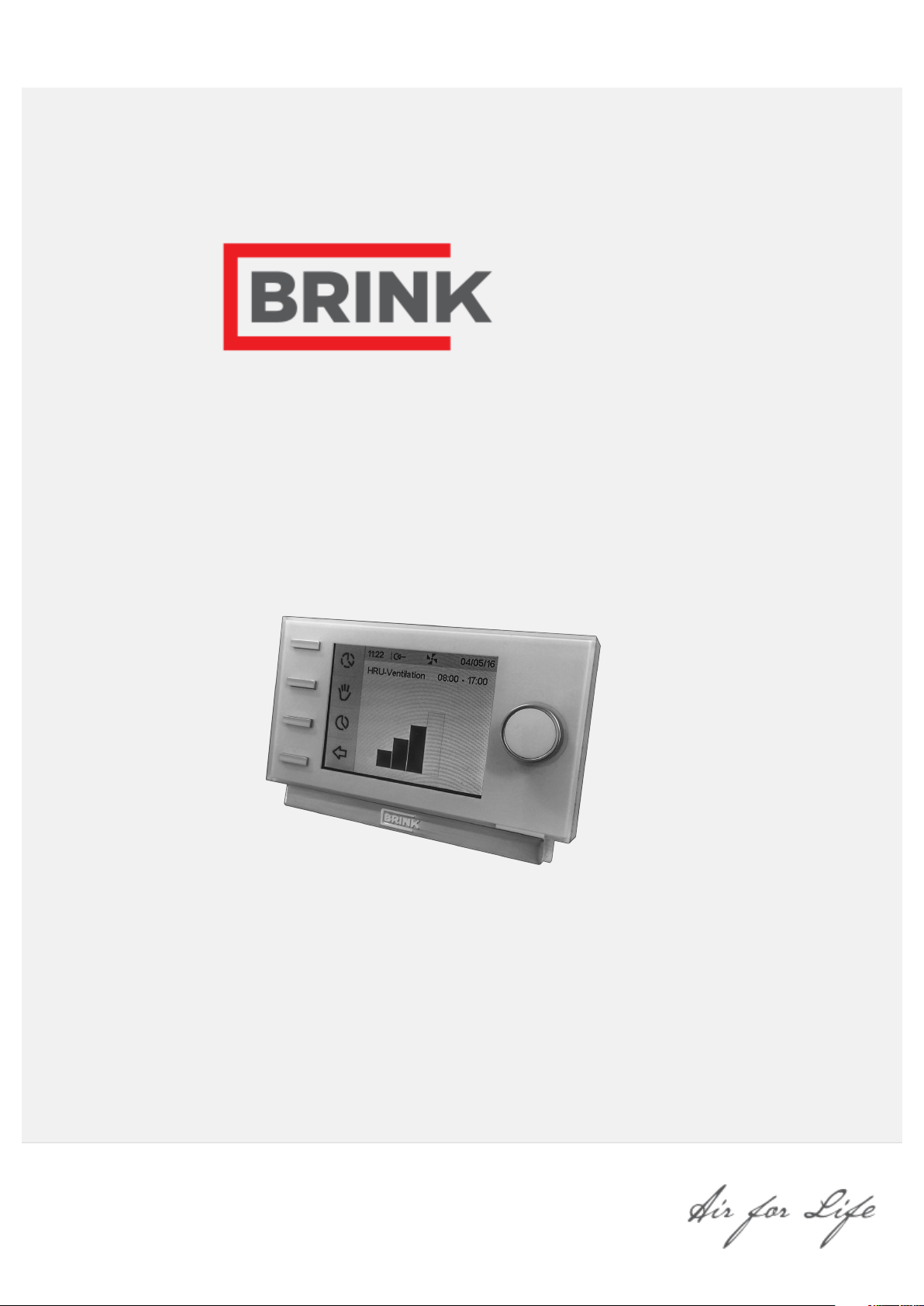
Brink Air Control
English
Page 2

Contents
1 User manual. . . . . . . . . . . . . . . . . . . . . . . . . . . . . . . . . . . . 3
1.1 Descripon Brink Air Control. . . . . . . . . . . . . . . . . . . 3
1.2 Symbols used. . . . . . . . . . . . . . . . . . . . . . . . . . . . . . . 3
2 Technical specicaon. . . . . . . . . . . . . . . . . . . . . . . . . . . . 4
2.1 General product specicaon. . . . . . . . . . . . . . . . . . 4
2.2 Environment inuences. . . . . . . . . . . . . . . . . . . . . . . 4
2.3 Overview operaonal controls. . . . . . . . . . . . . . . . . 4
2.4 Overview display version main screen. . . . . . . . . . . 4
2.5 Venlaon modes. . . . . . . . . . . . . . . . . . . . . . . . . . . . 4
3 Precauonary measures and safety instrucons. . . . . . . 5
3.1 General. . . . . . . . . . . . . . . . . . . . . . . . . . . . . . . . . . . . 5
3.2 During placement. . . . . . . . . . . . . . . . . . . . . . . . . . . . 5
3.3 During use. . . . . . . . . . . . . . . . . . . . . . . . . . . . . . . . . . 6
3.4 During maintenance. . . . . . . . . . . . . . . . . . . . . . . . . . 6
3.5 For the environment. . . . . . . . . . . . . . . . . . . . . . . . . . 6
4 Assembly and installaon (to be performed by the
installer). . . . . . . . . . . . . . . . . . . . . . . . . . . . . . . . . . . . . . . . . 7
4.1 Assembly. . . . . . . . . . . . . . . . . . . . . . . . . . . . . . . . . . . 7
4.1.1 Disconnecng the operaonal module from the
wall bracket. . . . . . . . . . . . . . . . . . . . . . . . . . . . . . . . . 7
4.1.2 Mounng the wall bracket. . . . . . . . . . . . . . . . . 7
4.1.3 Electrical connecon. . . . . . . . . . . . . . . . . . . . . 7
4.1.4 Replacing the operaonal module in the wall
bracket. . . . . . . . . . . . . . . . . . . . . . . . . . . . . . . . . . . . . 8
4.2 Installaon. . . . . . . . . . . . . . . . . . . . . . . . . . . . . . . . . . 8
4.2.1 Seng language. . . . . . . . . . . . . . . . . . . . . . . . . 8
4.2.2 Seng me. . . . . . . . . . . . . . . . . . . . . . . . . . . . . 9
4.2.3 Seng date. . . . . . . . . . . . . . . . . . . . . . . . . . . . . 9
4.2.4 Selecng a device connected to the Brink Air
Control . . . . . . . . . . . . . . . . . . . . . . . . . . . . . . . . . . . . 10
5 Descripon of operaon; manner of use. . . . . . . . . . . . 11
5.1 Navigaon: general descripon. . . . . . . . . . . . . . . . 11
5.2 Selecng a device connected to the Brink Air Control
. . . . . . . . . . . . . . . . . . . . . . . . . . . . . . . . . . . . . . . . . . . . . 11
5.3 Weekly programmes P1, P2 and P3. . . . . . . . . . . . 11
5.3.1 Standard sengs P1, P2 and P3. . . . . . . . . . . 11
5.3.2 Creang a P1 programme. . . . . . . . . . . . . . . . 12
5.3.3 Creang a P2 programme. . . . . . . . . . . . . . . . 13
5.3.4 Creang a P3 programme. . . . . . . . . . . . . . . . 14
5.4 Acvang programma type (P1, P2 or P3). . . . . . . 16
5.5 Temperarily overriding progranmme. . . . . . . . . . . 16
5.6 Overriding programme for a longer period of me 16
5.7 Seng venlaon mode values. . . . . . . . . . . . . . . 17
5.8 Retrieving sengs. . . . . . . . . . . . . . . . . . . . . . . . . . 18
5.9 Factory seng connected device. . . . . . . . . . . . . . 18
6 Maintenance. . . . . . . . . . . . . . . . . . . . . . . . . . . . . . . . . . . 19
6.1 General maintenance. . . . . . . . . . . . . . . . . . . . . . . . 19
6.2 Cleaning or replacing lter. . . . . . . . . . . . . . . . . . . . 19
6.2.1 Filter nocaon. . . . . . . . . . . . . . . . . . . . . . . 19
6.2.2 Removing, cleaning or replacing. . . . . . . . . . . 19
6.2.3 Re-seng lter nocaon. . . . . . . . . . . . . . . 19
7 Dismanteling. . . . . . . . . . . . . . . . . . . . . . . . . . . . . . . . . . . 20
8 Repair. . . . . . . . . . . . . . . . . . . . . . . . . . . . . . . . . . . . . . . . . 21
9 Environment. . . . . . . . . . . . . . . . . . . . . . . . . . . . . . . . . . . 22
10 Troubleshoong and quarantee. . . . . . . . . . . . . . . . . . 23
10.1 Troubleshoong. . . . . . . . . . . . . . . . . . . . . . . . . . . 23
10.2 Quarantee. . . . . . . . . . . . . . . . . . . . . . . . . . . . . . . . 23
11 Appendix 1: Standard sengs weekly programmes. . 24
11.1 Standard programme P1. . . . . . . . . . . . . . . . . . . . 24
11.2 Standard programme P2. . . . . . . . . . . . . . . . . . . . 25
11.3 Standard programme P3. . . . . . . . . . . . . . . . . . . . 26
11 Appendix 2 Images. . . . . . . . . . . . . . . . . . . . . . . . . . . . . 27
11.1 Image overview operaonal control. . . . . . . . . . . 27
11.2 Image overview display. . . . . . . . . . . . . . . . . . . . . 27
11.3 Image venlaon modes. . . . . . . . . . . . . . . . . . . . 28
11.4 Image disconnecng operaonal module. . . . . . 28
11.5 Image electrical connecon. . . . . . . . . . . . . . . . . . 28
11.6 Image wall bracket. . . . . . . . . . . . . . . . . . . . . . . . . 29
11.7 Image replacing operaonal module. . . . . . . . . . 29
11.8 Image lter nocaon. . . . . . . . . . . . . . . . . . . . . 30
11.9 Image main menu display. . . . . . . . . . . . . . . . . . . 30
11.10 Image reseng lter. . . . . . . . . . . . . . . . . . . . . . 31
11.11 Image device informaon menu. . . . . . . . . . . . . 32
11.12 Image basic sengs. . . . . . . . . . . . . . . . . . . . . . . 33
11.13 Image installer menu. . . . . . . . . . . . . . . . . . . . . . 34
Page 3

1 User manual
Dear client,
Thank you for buying the Brink Air Control. This user’s manual contains all required information to quickly
become familiar with the product. We kindly request you to carefully go through this information before using the
product.
This user’s manual is intended for the Brink Air Control installer and end user. You can retrieve the required
information from the user’s manual via the table of contents.
This is an extended user’s manual. A Quick Start Guide is available, in addition to this user’s manual.
Take good care of this user’s manual!
For more information or ordering manuals, please contact:
Brink Climate Systems B.V.
Mailbox 11
NL-7950 AA, Staphorst, The Netherlands
T: +31 (0) 522 46 99 44
F. +31 (0) 522 46 94 00
E. [email protected]
www.brinkclimatesystems.com
1.1 Description Brink Air Control
Intended and unintended use
The Brink Air Control should be used in combination with products that have been approved by Brink Climate
Systems B.V..
Brink Climate Systems B.V. cannot be held responsible for possible damage caused by improper, incorrect or
unwise use. It is important that one understands this user’s manual completely.
Working with other devices
The Brink Air Control is connected to other devices. The HRU (Heat Recovery Unit) is co-dependent on these
devices’ operation for its proper functioning. These devices’ presence and proper functioning are prerequisites for
using the Brink Air Control.
1.2 Symbols used
Warning!
The user can (seriously) injure himself or seriously damage the product.
A warning is indicative of a risk of damage to the user or product, if the user does not execute
the procedures carefully.
Careful!
The product can be endangered. “Careful” is indicative of a risk of damage to the product, if the
user does not execute the procedures carefully.
Take note!
A remark with supplementary information for the user. A remark draws the user’s attention to
possible problems.
Brink / 3Brink Air Control 614884-A
Page 4

2 Technical specification
2.1 General product specification
Product description
Name: Brink Air Control
Model/ Type: Brink Climate Systems B.V.
Technical product specifications
Electricity: 15 to 24 Volt
Power consumpon: 1,5 Wa
Protecon class: IP30
Power reserve: > 48 hours
Ambient conditions
Ambient temperature: 0 °C to 50 °C
Storage temperature: -20 °C to 60 °C
Humidity: 10% to 90%
Other: Exclusively for indoor use
2.2 Environment influences
The Brink Air Control should be placed and used in a space with the correct ambient conditions for proper
operation. The Brink Air Control may only be mounted on the indoors, but not on the vicinity of a heat source, a
radiator, in a draft or in a humid environment. The Brink Air Control may also not be exposed to direct radiation
heat (sun light). The Brink Air Control may also not be mounted in the vicinity of a magnetic field. This could
damage internal components.
2.3 Overview operational controls
The Brink Air Control has a number of buttons with which the device can be operated: (® Image overview
operational control page 27)
2.4 Overview display version main screen
(® Image overview display page 27)
2.5 Ventilation modes
The Brink Air Control has four ventilation modes (®
ventilation mode yourself (for more information see ® Description of operation; manner of use page 11 ). You can
adjust every ventilation mode yourself (for more information ® Setting ventilation mode values page 17 ). You can
retrieve the set values at the Device information menu (see ®
settings page 18 ).
Image ventilation modes page 28). You can activate a
Image basic settings page 33 and ® Retrieving
Brink Air Control 614884-A
Page 5
3 Precautionary measures and
safety instructions
3.1 General
Warning!
The installation and assembly activities required to commission your Brink Air Control should be
performed by an installer approved by Brink Climate Systems B.V..
Warning!
Immediately remove the power from your Brink Air Control by removing the connected device’s
plug from the socket, if:
· Parts of the Brink Air Control lie open, are pierced or had fallen hard;
· The power cable is damaged;
· The screen is cracked or broken.
Then contact Brink Climate Systems B.V. or you supplier.
Take note!
Never use parts other than original parts.
Take note!
Only use the Brink Air Control indoors, at temperatures between 0 °C and 50 °C and with a relative
humidity between 10% and 90%.
Take note!
All settings (excluding the filter message) will be lost if the Brink Air Control breaks down or if the
factory settings are reset. There is no backup available.
3.2 During placement
Take note!
Assembly and installation should be performed by an installer approved by Brink Climate Systems
B.V.. The following requirements should be taken into account during placement:
The Brink Air Control should be placed at a height of approximately 1.65 meters above the
·
The Brink Air Control may not be covered, for example, by a curtain or a cabinet;
·
floor;
· Consult paragraph ® Environment influences page 4 for environmental requirements.
Brink / 5Brink Air Control 614884-A
Page 6

3.3 During use
Take note!
Settings, which have not been described in this user’s manual, are intended for installers
approved by Brink Climate Systems B.V.. Do not change these by yourself.
3.4 During maintenance
Careful!
Clean the screen with a soft cloth.
Careful!
Never apply water and/or (cleaning) liquid to the screen.
3.5 For the environment
Take note!
The Brink Air Control may not be removed as unsorted urban waste, but should be treated
separately.
Take note!
Make enquiries within your own region, where the Brink Air Control can be handed in when
use has been terminated. Do not throw away electrical devices or parts, but check if (parts
of) the Brink Air Control cannot be handed in, recycled or re-used.
Brink Air Control 614884-A
Page 7

4 Assembly and installation (to be
performed by the installer)
Assembly and installation should be performed by an installer approved by Brink Climate Systems B.V..
4.1 Assembly
You should perform the steps, described in paragraph (®
bracket page 7) through paragraph (® Replacing the operational module in the wall bracket page 8), one by one,
to assemble the Brink Air Control.
Disconnecting the operational module from the wall
4.1.1 Disconnecting the operational module from the wall bracket
Disconnect the operational module from the wall bracket. Perform the following actions ( ® Image disconnecting
operational module page 28 ):
Slide the control unit upward over the two guide profiles of the wall bracket until the control
·
unit can be taken off.
4.1.2 Mounting the wall bracket
The wall bracket can be aached to a wall box (Ø 55 mm) or can be directly mounted on the wall with screws and plugs.
Screw the wall bracket onto the wall in the correct position. Here one must use the mounting holes
·
in the wall bracket (® Image wall bracket page 29).
Take note!
Consult ( ® During placement page 5) for more information on placing the Brink Air Control.
4.1.3 Electrical connection
The following actions should be performed to connect the Brink Air Control electrically ( ® Image electrical
connection page 28 ):
Feed the two-core wire (from the device to be connected) through via opening at the back of the
·
wall bracket.
Check that the cables’ ends have been stripped in the correct manner. If this is not the case, do so.
·
Screw the cable to the terminal No. 1 and No. 2. Consult the installation instructions of the device
·
to be connected, for more information on the correct connection.
Brink / 7Brink Air Control 614884-A
Page 8

4.1.4 Replacing the operational module in the wall bracket
Place the operational in the wall bracket mounted on the wall. Perform the following actions for this ( ® Image
replacing operational module page 29 ):
Slide the control unit downward over the two guide profiles. Make sure the guide profiles of the wall bracket fit snugly in the cutouts of the control unit provided for that purpose.
·
Take note!
The operational module should click onto the wall bracket. Only then is a proper electrical connection established.
4.2 Installation
4.2.1 Setting language
You can set the language in which the menus are presented. Perform the following actions to set the language
(see ® Image overview operational control page 27 , ® Image overview display page 27 & ® Image basic
settings page 33 ):
Press returnkey "2" as many times as necessary to get to the main screen
·
Press setting knob "1"; ‘Main Menu’ opens
·
Select ‘Basic Settings’ by turning setting knob "1"
·
Press setting knob "1";‘Basic Settings’ opens
·
Select ‘Language’ by turning setting knob "1"
·
Press setting knob "1"; ‘Language’ opens
·
Select the desired language by turning setting knob "1"
·
Press setting knob "1" to set the selected language
·
Press returnkey "2" as many times as necessary to get to the main screen
·
Take note!
The names of the described menu items will not correspond with this user manual’s menu items if
the Brink Air Control is set to a language other than Dutch.
Brink Air Control 614884-A
Page 9

4.2.2 Setting time
You can set the time. The time is visible on the main screen The Brink Air Control only has 24 hour
representation. Perform the following actions to set the time ( ® Image overview operational control page 27 ):
Press returnkey "2"as many times as necessary to get to the main screen
·
Press setting knob "1"; ‘Main Menu’ opens
·
Select ‘Basic Settings’ by turning setting knob "1"
·
Press setting knob "1"; ‘Basic Settings’ opens
·
Select ‘Clock’ by turning setting knob "1"
·
Press setting knob "1"; ‘Clock’ opens
·
Change the time by turning setting knob "1"
·
Press setting knob "1" to confirm the time
·
Repeat the previous two steps for both the minutes and seconds
·
Press returnkey "2" as many times as necessary to get to the main screen
·
4.2.3 Setting date
You can set the date. The date is visible on the main screen. Perform the following actions to set the date(see ®
Image overview operational control page 27 , ® Image main menu display page 30 & ® Image basic settings
page 33 ):
Press returnkey "
·
Press setting knob "
·
Select ‘Basic Settings’ by turning setting knob "
·
Press setting knob "
·
Select ‘Date’ by turning setting knob "
·
Press setting knob "
·
Change the day by turning setting knob "
·
Repeat the previous two steps for both the months and the year
·
Press returnkey "
·
2" as many times as necessary to get to the main screen
1"; ‘Main Menu’ opens
1"
1"; ‘Basic Settings’ opens
1"
1" ‘Date’ opens
1"
2" as many times as necessary to get to the main screen
Brink / 9Brink Air Control 614884-A
Page 10

4.2.4 Selecting a device connected to the Brink Air Control
You can choose the device you want to regulate with the control if multiple devices are connected to Brink Air
Control. Proceed as follows to set the appliance selection (see ® Image overview operational control page 27 &
®
Image installer menu page 34 ):
Press returnkey "2" as many times as necessary to get to the main screen
·
Press setting knob "1"; ‘Main Menu’ opens
·
Select ‘Installer’ by turning setting knob "1"
·
Press setting knob "1";‘Installer’ opens
·
Select ‘Device’ by turning setting knob "1"
·
Press setting knob "1" to confirm selected device
·
If only one appliance is connected, no choice is offered and only Heat Recovery Unit appliance is displayed.
Brink Air Control 614884-A
Page 11

5 Description of operation; manner
of use
You can increase or decrease the ventilation mode with the Brink Air Control. You can do this by setting a
program. You can temporarily override the program while it is running.
5.1 Navigation: general description
Navigating through menus
The Brink Air Control has menus that you can navigate through. For this you use setting knob "1" (see ®
overview operational control page 27 ). You scroll through the menus by turning the setting knob "1" ( ® Image
main menu display page 30 ) You can open a selected menu-item by pressing the navigation button( ® Image
main menu display page 30 ).
Return to the main screen
The main screen ( ® Image overview display page 27 ) is the Brink Air Control start screen. You can always return
to the main screen by pressing on the returnkey "2" ( ® Image overview operational control page 27 ) a few
times. The number of times you need to press return depends on how deep you have gone into the menu. U need
not be afraid of pressing return too frequently.
Image
5.2 Selecting a device connected to the Brink Air Control
You can choose the device you want to regulate with the control if multiple devices are connected to Brink Air
Control ( ® Selecting a device connected to the Brink Air Control page 10 ).
5.3 Weekly programmes P1, P2 and P3
You can programme the regulaon of the venlaon mode in a weekly program. You can choose from programs P1, P2
and P3.
Program P1
With this you create a day program for every day of the week.
Program P2
With this you create two day programs.
One day program for weekdays ‘mo-fri’ and one day program for the weekend ‘sa-su’.
Program P3
With this you create seven day programs.
Separately for every day of the week.
5.3.1 Standard settings P1, P2 and P3
The Brink Air Control has standard set weekly programmes. You can find these settings in appendix 1 (®
Appendix 1: Standard settings weekly programmes page 24).
Brink / 11Brink Air Control 614884-A
Page 12

5.3.2 Creating a P1 programme
Image overview operaonal control page 27
®
Press returnkey "2" as many times as necessary to get to the main screen
·
Press setting & activating time program knob "3"; ‘Setting & activating timer programme’ opens
·
Select ‘P1: week’ by turning setting knob "1"
·
Press setting knob "1"; ‘P1: week’ opens
·
You have a choice from ‘Period 1’, ‘Period 2’, ‘Period 3’, ‘Period 4’, ‘Period 5’ and ‘Period 6’. Every period is a part
of the day in which you can set a ventilation position.
Perform the following actions to set period 1:
Select ‘P1’ by turning setting knob "1"
·
Press setting knob "1";‘Period 1’ opens
·
Select ‘Start Time’ by turning setting knob "1"
·
Press setting knob "1"; ‘Start Time’ opens
·
Change the start time by turning setting knob "1"
·
You have a range of between 3.00u and 2.59u
·
If in a period the time is turned back so far that lines appear, that period and the one above it will
be deleted.
Press setting knob "1" to confirm the start time
·
Now set the venlaon mode for period 1. Perform the following acons for this:
Select ‘Ventilatiestand’ by turning "
·
Press "
·
Set the ventilation mode for period 1 by turning "
·
Press "1" to conrm the venlaon mode for period 1
·
1" , ‘Ventilatiestand’ opens
1"
1"
You have set the ventilation mode for period 1. You can set period 2 through 6 in the same manner. A period ends
when a new one starts.
Brink Air Control 614884-A
Page 13

5.3.3 Creating a P2 programme
® Image overview operaonal control page 27
Press returnkey "2" as many times as necessary to get to the main screen
·
Press setting & activating time program knob "3"; ‘Setting & activating timer programme’ opens
·
Select ‘P2: week/weekend’ by turning setting knob "1"
·
Press setting knob "1"; ‘P1: week/weekend’ opens
·
You can choose between ‘Week’ and ‘Weekend’. With ‘Week’ you can set a day program for Monday through
Friday. With ‘Weekend’ you can set a day program for Saturday and Sunday.
Week
Select ‘Week’ by turning setting knob "1"
·
Press setting knob "1"; ‘Week’ opens
·
(*) You have a choice from ‘Period 1’, ‘Period 2’, ‘Period 3’, ‘Period 4’, ‘Period 5’ and ‘Period 6’. Every period is a
part of the day in which you can set a ventilation mode.
Perform the following actions to set period 1:
Select ‘Period 1’ by turning setting knob "
·
Press setting knob "
·
Select ‘start time’ by turning setting knob "
·
Press setting knob "
·
Change ‘start time’ by turning setting knob "
·
Press setting knob "
·
Now set the ventilation mode for period 1.
Perform the following actions for this:
Select ‘Ventilatiestand’ by turning setting knob "
·
Press setting knob "
·
Set the ventilation mode for period 1 by turning setting knob "
·
1"; ‘Period 1’ opens
1"; ‘start time’ opens
1" to confirm start time
1";‘Ventilatiestand’ opens
1"
1"
1"; You have a range of between 3.00 hrs and 2.59 hrs
1"
1"
Press setting knob "
·
You have set the ventilation mode for period 1 You can set period 2 through 6 in the same manner. A period ends
when a new one starts.
1" to confirm the airflow for period 1
Brink / 13Brink Air Control 614884-A
Page 14

Weekend
Follow the steps from paragraph 5.3.3, until you have a choice between ‘Week’ and ‘Weekend’
·
Select ‘Weekend’ by turning setting knob "1"
·
Press setting knob "1"; ‘Weekend’ opens
·
Continue the steps from paragraph 5.3.3 at (*)
·
5.3.4 Creating a P3 programme
® Image overview operaonal control page 27
Press returnkey "2" as many times as necessary to get to the main screen
·
Press setting & activating time program knob "3"; ‘Setting & activating timer programme’ opens
·
Select ‘P3: day’ by turning setting knob "1"
·
Press setting knob "1"; ‘P3: day’ opens
·
(*) You can choose from the days between ‘Monday’ through ‘Sunday’. You perform the following steps to set a day
program for Monday:
Select ‘Monday’ by turning setting knob "
·
Press setting knob "
·
1"; ‘Monday’ opens
1"
You have a choice from ‘Period 1’, ‘Period 2’, ‘Period 3’, ‘Period 4’, ‘Period 5’ and ‘Period 6’. Every period is a part of the day
in which you can set a venlaon posion.
Select 'Period 1' by turning setting knob "
·
Press setting knob "
·
Select ‘Start time’ by turning setting knob "
·
Press setting knob "
·
Change ‘Start time’ by turning setting knob "
·
Press setting knob "
·
1"; ‘Period 1’ opens
1";‘Start time’ opens
1" to confirm ‘Start time’
1"
1"
1" ; You have a range of between 3.00u and 2.59u
Now set the ventilation mode for period 1.
Perform the following actions for this:
Select 'Ventilatiestand' by turning setting knob "
·
1"
Brink Air Control 614884-A
Page 15

Press setting knob "1"; ‘Ventilatiestand’ opens
·
Set the ventilation mode for period 1 by turningsetting knob "1"
·
Press setting knob "1" to confirm the ventilation mode for period 1
·
You have set the ventilation mode for period 1 You can set period 2 through 6 in the same manner. A period ends
when a new one starts.
If you have created a day program for Monday, you can do the same for the other days of the week. Then repeat
the steps from paragraph 5.3.4, but, after (*) choose another day instead of ‘Monday’.
Brink / 15Brink Air Control 614884-A
Page 16

5.4 Activating programma type (P1, P2 or P3)
The Brink Air Control has three types of weekly programs P1, P2 and P3. You can program the weekly programs
by yourself, for more information see paragraph .® Weekly programmes P1, P2 and P3 page 11.
Perform the following acons if you wish to program one of the weekly programs ( ®
page 27 ):
Press returnkey "2" as many times as necessary to get to the main screen
·
Press setting & activating time program knob "3"; ‘Setting & activating timer programme’ opens
·
Select ‘Active program’ by turning setting knob "1"
·
Press setting knob "1";‘Active program’ opens
·
Select ‘P1, P2 or P3’ by turning setting knob "1"
·
Press setting knob "1" to activate P1, P2 or P3
·
Image overview operaonal control
5.5 Temperarily overriding progranmme
You can temporarily override the program. You need to perform the following actions for this (®
operational control page 27 ):
Press returnkey "
·
2" as many times as necessary to get to the main screen.
Image overview
Press knob "
·
Turn setting knob "
·
Take note!
It is stated at the top of your screen, how long the newly set ventilation mode applies. The program
will be enabled again after this period of time. The override period will be 30 minutes if you
overruled the device in the maximum position. You can also undo this by pressing returnkey "2".
Returnkey "2" can not be operated until some 10 seconds after the latest setting!
5"; ‘Bypassing the timer programme’ opens.
1" to temporarily set the ventilation mode.
5.6 Overriding programme for a longer period of time
A set program me can be overriden manually, for example, during holidays. Perform the following acons to overrule the
program ( ®
Image overview operaonal control page 27 ):
Press returnkey "
·
Press knob "
·
Turn setting knob "
·
2" as many times as necessary to get to the main screen
4" and ‘Manual’ appears in the display
1" to set the ventilation position
Brink Air Control 614884-A
Page 17

The manual position now overrules the programme. Press returnkey "2" if you wish to undo the manual position.
Returnkey "2" can not be operated until some 10 seconds after the latest setting!
5.7 Setting ventilation mode values
You can set a ventilation mode’s value by yourself.
Perform the following actions for this (see ® Image overview operational control page 27 & ® Image installer
menu page 34 ):
Press returnkey "2" as many times as necessary to get to the main screen
·
Press setting knob "1"; ‘Main Menu’ opens
·
Select ‘Installer’ by turning setting knob "1".
·
Turn setting knob "1" to select the desired appliances
·
Press setting knob "1" to confirm the desired appliance (or select the choice HRV appliance if only
·
one appliance is connected).
Select ‘Device settings’ by turning setting knob "1".
·
Press setting knob "1"; ‘Device settings’ opens
·
Select ‘Airflow 0 (Holiday)’ by turning setting knob "1"
·
Take note!
‘Airflow 0 (Holiday)’ refers to ventilation mode
‘Airflow 1 (Reduced)’ refers to ventilation mode
‘Airflow 2 (Normal)’ refers to ventilation mode
‘Airflow 3 (High)’ refers to ventilation mode
Set Airflow 0 (Holiday) by turning setting knob "1".
·
Press setting knob "1" to confirm the set value for Airflow 0 (Holiday)
·
You can set debit 1 through 3 in the same manner as described above for Airow 0 (Holiday).
Take note!
You cannot feed in a value, lower than value of a lower Airflow position, for a higher (Airflow Holiday
< Airflow Reduced < Airflow Normal < Airflow High).
Brink / 17Brink Air Control 614884-A
Page 18

5.8 Retrieving settings
You can retrieve the current settings from the Brink Air Control:
Press returnkey "2" as many times as necessary to get to the main screen
·
Press setting knob "1" ‘Main Menu’ opens
·
Turn setting knob "1" to select the desired appliances
·
Press setting knob "1" to confirm the desired appliance (or select the choice HRV appliance if only
·
one appliance is connected).
Select ‘Device information’ by turning setting knob "1" .
·
Press setting knob "1"; ‘Device information’ opens
·
Turnsetting knob "1" to display the desired appliances
·
Take note!
You can look at, but not change, the settings via the info menu.
5.9 Factory setting connected device
A device has been connected to the Brink Air Control. It is possible to set back all this device’s settings to the
factory settings. Perform the following actions for this ( ®
Press returnkey "
·
Pressetting knob "
·
Select ‘Installation Settings’ by turning setting knob "
·
Press setting knob "
·
Select ‘Installer’ by turning setting knob "
·
Press setting knob "
·
Select ‘Factory Setting’ by turning setting knob "
·
Press setting knob "
·
Turn setting knob "
·
2" as many times as necessary to get to the main screen
1" ‘Main Menu’ opens
1"; ‘Installation Settings’ opens
1"; ‘Installer’ opens
1";‘Factory Setting’ opens
1" to select the option 'yes'
Image overview operational control page 27 ):
1".
1".
1".
Press setting knob "
·
if only one appliance is connected).
The settings are put back to the factory settings. Selecting factory setting will restore all step
·
numbers to the original factory setting. All fault messages will be deleted as well.
1" to confirm the desired 'Factory Setting' (or select the choice HRV appliance
Brink Air Control 614884-A
Page 19

6 Maintenance
6.1 General maintenance
Careful!
Clean the screen with a soft cloth.
Careful!
Never apply water and/or (cleaning) liquid to the screen.
6.2 Cleaning or replacing filter
6.2.1 Filter notification
The filters in the device, connected to the Brink Air Control, should be cleaned or replaced when the text ‘FILTER’
appears on the Brink Air Control display ( ® Image filter notification page 30 ).
6.2.2 Removing, cleaning or replacing
Consult the manual of the device connected to the Brink Air Control for removing, cleaning and replacing filters.
6.2.3 Re-setting filter notification
You can reset the filter notification after you have cleaned or replaced the filter (or the filters). For this you press
the setting knob "1" for at least five seconds (see ®
resetting filter page 31 ).
Press returnkey "2" to get to the main screen.
The text filter on the Brink Air Control display disappears.
Image overview operational control page 27 & ® Image
Brink / 19Brink Air Control 614884-A
Page 20

7 Dismanteling
Warning!
You are not permitted to dismantle the Brink Air Control or parts of the Brink Air Control by
yourself. This may only be done by a maintenance mechanic approved by Brink Climate
Systems B.V..
Brink Air Control 614884-A
Page 21

8 Repair
Warning!
You are not permitted to open or repair the Brink Air Control or parts of the Brink Air Control by
yourself. This may only be done by a maintenance mechanic approved by Brink Climate Systems
B.V..
Brink / 21Brink Air Control 614884-A
Page 22
9 Environment
Take note!
The Brink Air Control may not be removed as unsorted urban waste, but should be treated
separately.
Take note!
Make enquiries within your own region, where the Brink Air Control can be handed in when use
has been terminated. Do not throw away electrical devices or parts, but check if (parts of) the Brink
Air Control cannot be handed in, recycled or re-used.
RoHS-compliance
This product meets Directive 2011/65/EU of the European Parliament and the Council of 27 January 2003
regarding using certain environmentally hazardous substances in electronic equipment (RoHS) and the
amendments to the directive.
WEEE-notification
The WEEE-directive (Waste Electrical and Electronic Equipment), which came into force, as European law, on 13
February 2003, has resulted in an important change in treating electronic equipment at the end of their use cycle.
This directive’s objective is, firstly, preventing electronic equipment in waste and moreover promoting re-use,
recycling and other forms of recovering such waste in order to limit the amount of waste.
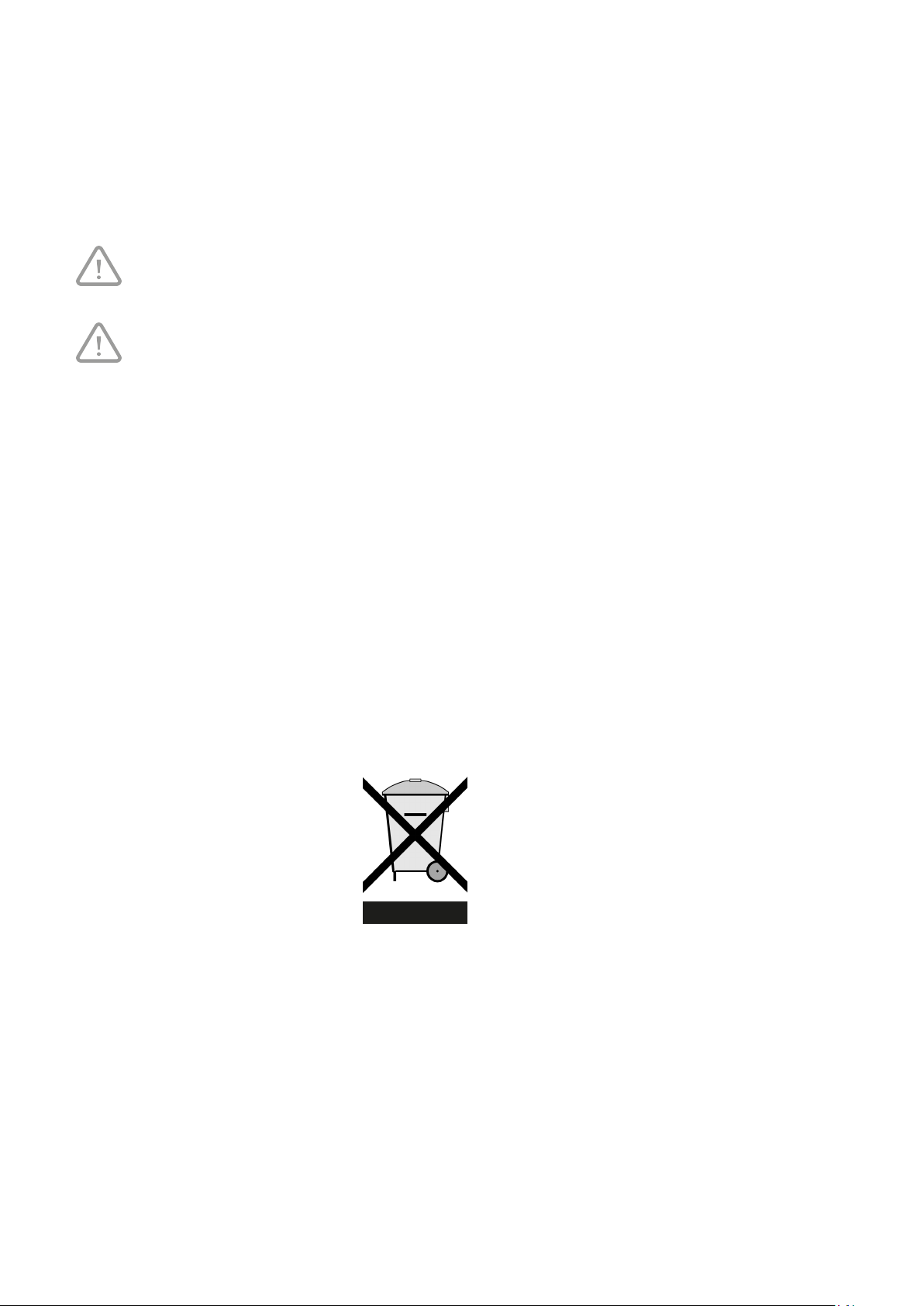
The WEEE-logo on a product or on the packaging indicates that this product may not be disposed of or thrown
away with domestic waste. You should dispose of all your old electronic or electrical equipment via special
collection points for such dangerous waste. Separate collection and correct treatment of our old electronic and
electrical equipment help us to maintain our natural resources.
Moreover, correct recycling guarantees the safety and health of humankind and the environment. For more
information on processing electronic and electrical equipment, re-use and collection points, please contact you
municipality, your local waste disposal company, the supplier from whom you purchased the device or the
device’s manufacturer.
WEEE logo
Handing in and recycling
Make enquiries within your own region, where the Brink Air Control can be handed in when use has been
terminated. Do not throw away electrical devices or parts, but check if (parts of) the Brink Air Control cannot be
handed in, recycled or re-used.
Brink Air Control 614884-A
Page 23
10 Troubleshooting and quarantee
10.1 Troubleshooting
See the installation instructions of the device connected to the Brink Air Control for troubleshooting for the error
notifications indicated on the Brink Air Control.
10.2 Quarantee
The Brink Air Control has been manufactured by Brink Climate Systems B.V. with care and in accordance with
high quality standards. The Brink Air Control operation is guaranteed for a period of twelve months from the time
of delivery. This guarantee is granted in accordance with Brink Climate Systems B.V. General Terms and
Conditions.
These can be found on www.brinkclimatesystems.com.
Do you want to claim under the guarantee?
You then have to make that known, in writing, via:
Brink Climate Systems B.V.
Mailbox 11
NL-7950 AA, Staphorst, The Netherlands
The right to guarantee lapses in case of incorrect or improper use of the Brink Air Control and failure to follow the user
indicaons in this user’s manual.
Warning!
Making changes to the Brink Air Control hardware or software is not permitted. This can have an
effect on the Brink Air Control proper operation and it that case all guarantees lapse.
Warning!
You are not permitted to open or repair the Brink Air Control or parts of the Brink Air Control by
yourself. In that case guarantees lapse.
Brink / 23Brink Air Control 614884-A
Page 24
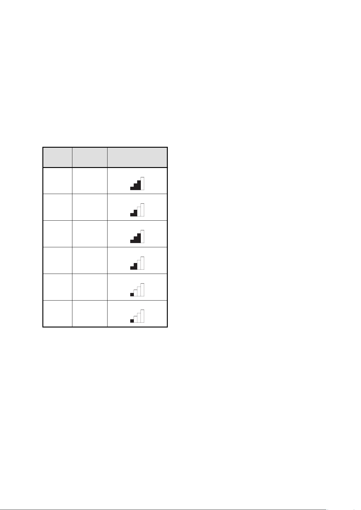
11 Appendix 1: Standard settings
weekly programmes
11.1 Standard programme P1
Week (Monday through Sunday)
Period Start time Ventilation mode
1 07.00
2 08.00
3 17.00
4 22.00
5 Not set
6 Not set
Brink Air Control 614884-A
Page 25
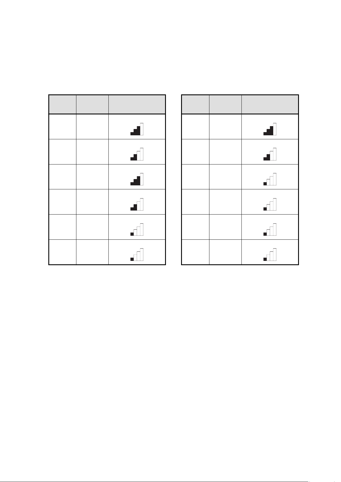
11.2 Standard programme P2
Week (Monday through Friday) Weekend (Saturday and Sunday)
Period Start time Ventilation mode Period Start time Ventilation mode
1 07.00 1 08.00
2 08.00 2 23.00
3 17.00 3 Not set
4 22.00 4 Not set
5 Not set 5 Not set
6 Not set 6 Not set
Brink / 25Brink Air Control 614884-A
Page 26
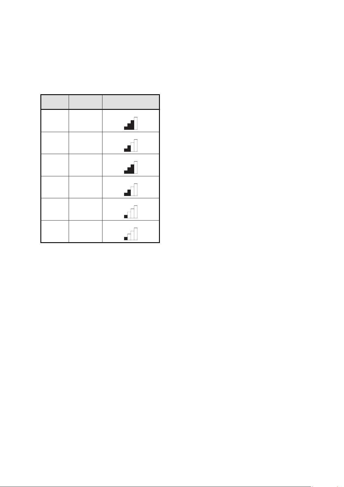
11.3 Standard programme P3
Monday
Period Start time Ventilation mode
1 07.00
2 08.00
3 17.00
4 22.00
5 Not set
6 Not set
Tuesday (the same as Monday)
Wednesday (the same as Monday)
Thursday (the same as Monday)
Friday (the same as Monday)
Saturday (the same as Monday)
Sunday (the same as Monday)
Brink Air Control 614884-A
Page 27
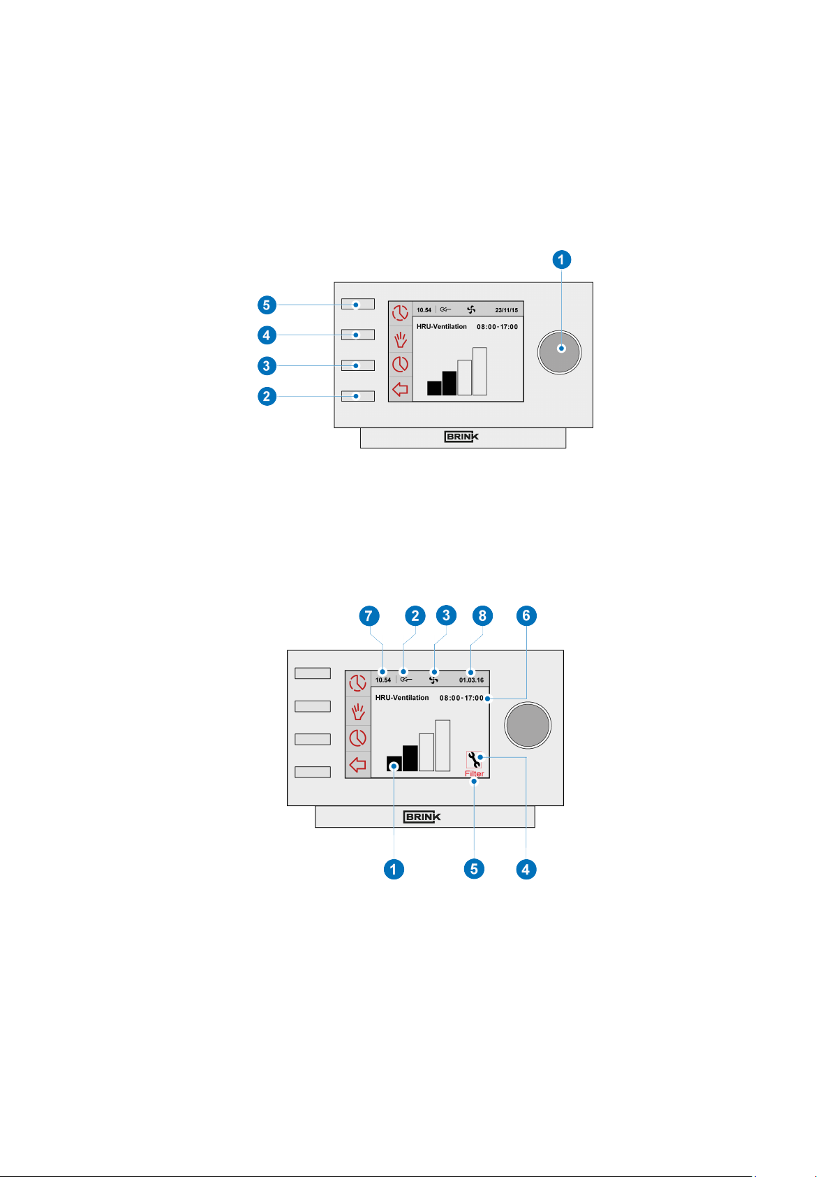
Appendix 2 Images
11.1 Image overview operational control
1 = Seng knob
2 = Return key
3 = Seng & acvang mer programme
4 = Manual control key
5 = Bypassing the mer programme
11.2 Image overview display
1 = Flow rate indicator
2 = eBus connecon indicator
3 = Fan indicator
4 = Fault symbol
5 = Filter message
6 = Current me block
7 = Current me
8 = Current date (day/ month/ year)
Brink / 27Brink Air Control 614884-A
Page 28
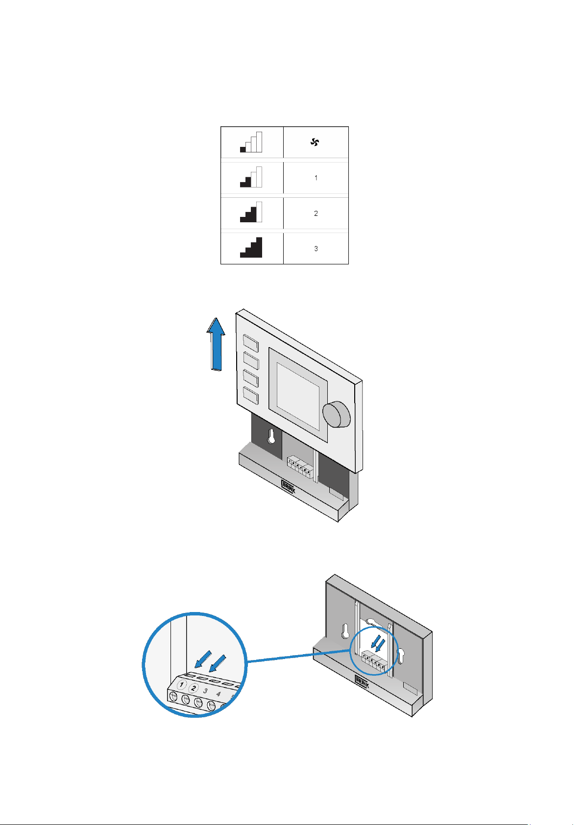
11.3 Image ventilation modes
11.4 Image disconnecting operational module
11.5 Image electrical connection
Brink Air Control 614884-A
Page 29
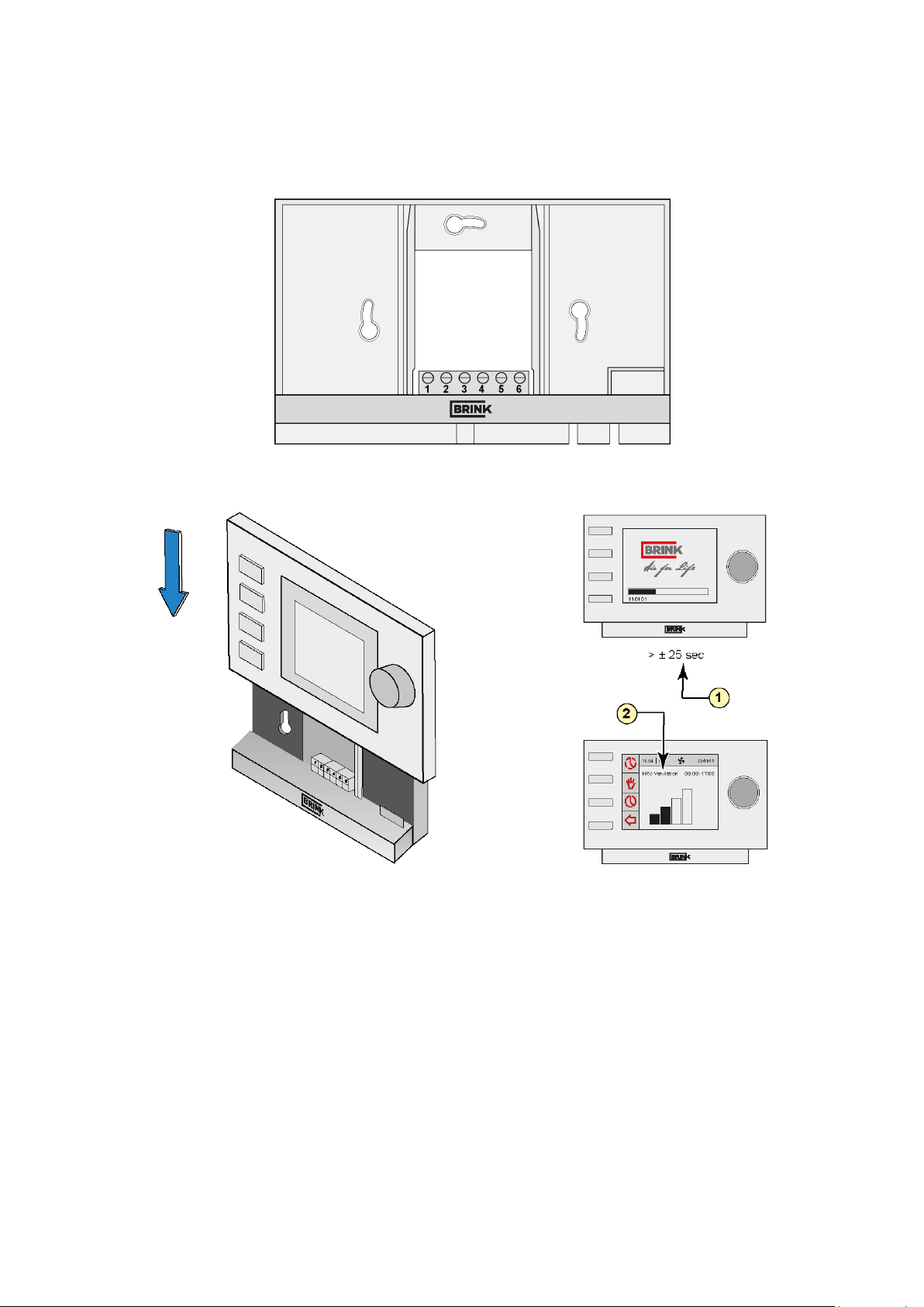
11.6 Image wall bracket
11.7 Image replacing operational module
1 = ± 25 seconds
2 = HRU ventilation
Brink / 29Brink Air Control 614884-A
Page 30
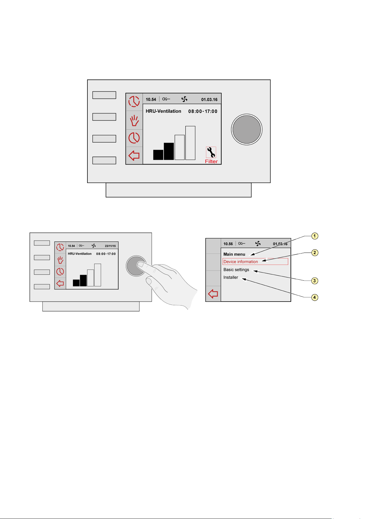
11.8 Image filter notification
11.9 Image main menu display
1 = Main menu
2 = Device information
3 = Basic settings
4 = Installer
Brink Air Control 614884-A
Page 31
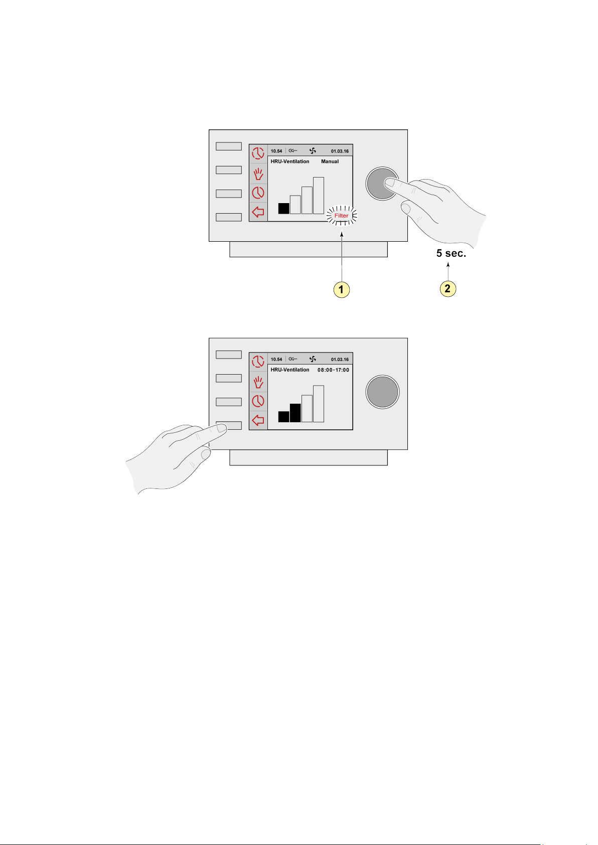
11.10 Image resetting filter
1 = Filter notification
2 = 5 seconds
Brink / 31Brink Air Control 614884-A
Page 32
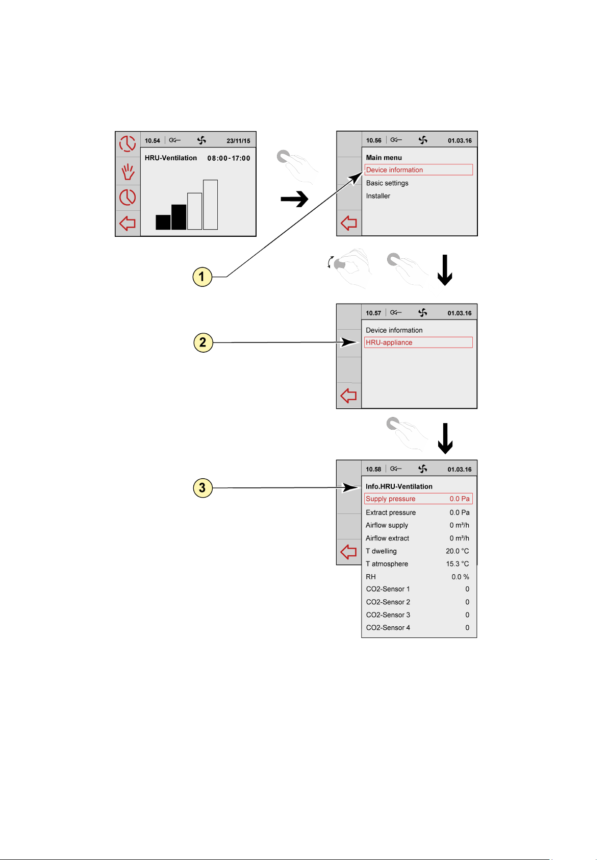
11.11 Image device information menu
1 = Device information
2 = HRU-appliance
3 = Information HRU ventilation
Brink Air Control 614884-A
Page 33
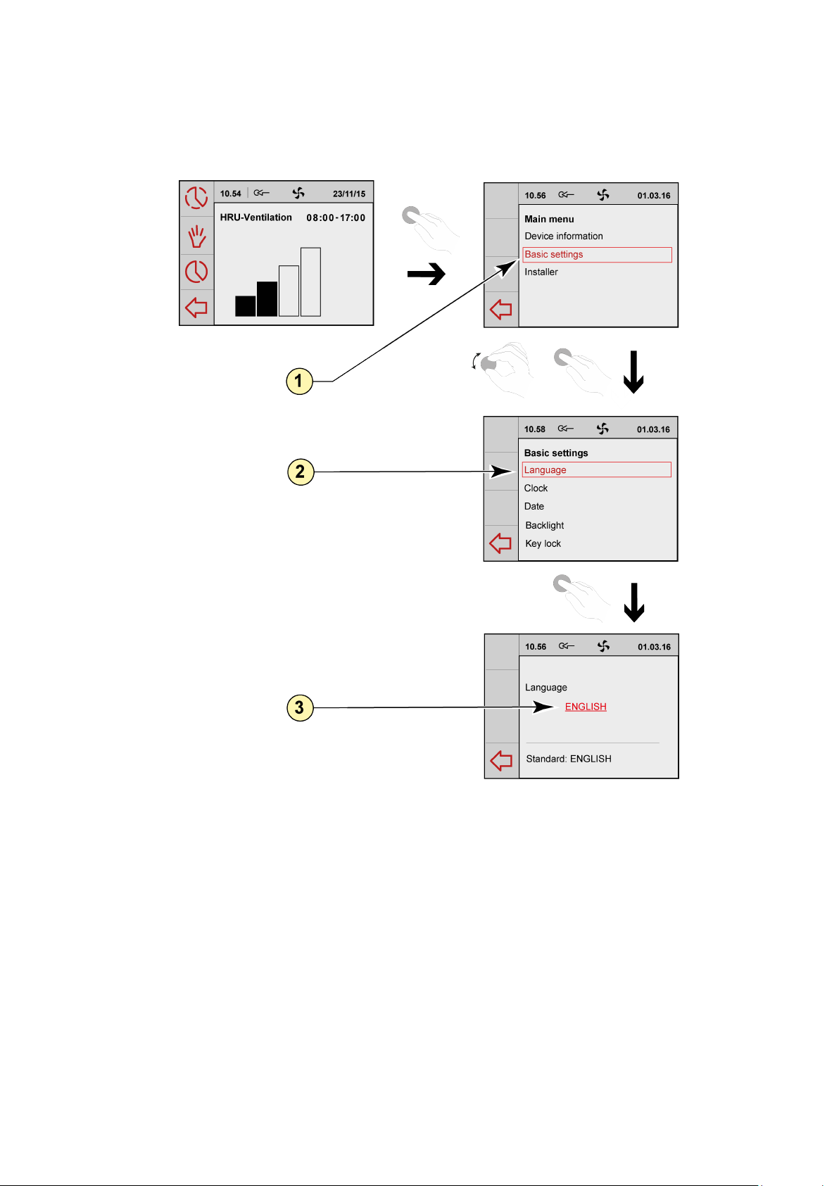
11.12 Image basic settings
1 = Basic settings
2 = Language
3 = English
Brink / 33Brink Air Control 614884-A
Page 34
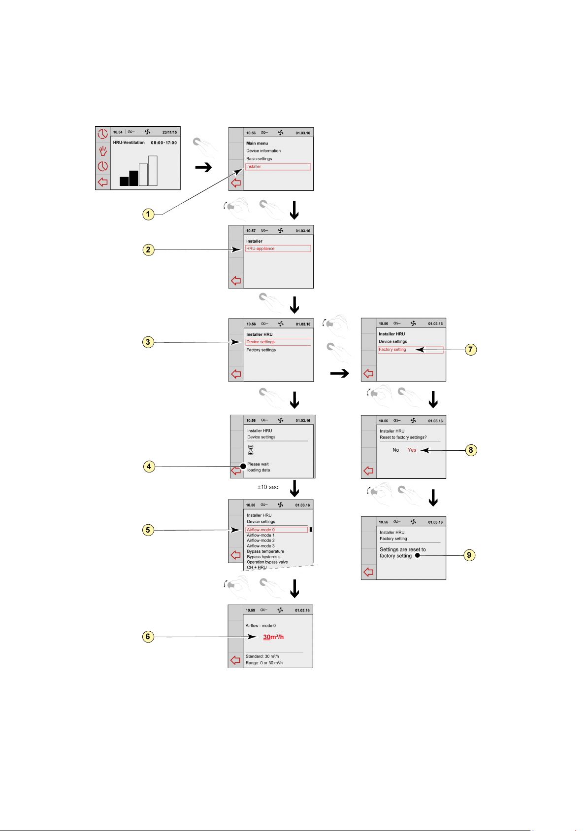
11.13 Image installer menu
1 = Installer 6 =
2 = HRU-appliance 7 = Factory seng
3 = Device sengs 8 = Yes
4 = Please wait: Loading data 9 = Sengs are reset to factory seng
5 = Airow-mode 1
Airow 30 m3/h
Brink Air Control 614884-A
Page 35
Brink Climate Systems BV
P.O. Box 11 NL-7950AA Staphorst
T +31 (0) 522 46 99 44
www.brinkclimatesystems.com
www.brinkairforlife.com
614884-A
 Loading...