

B&R Industrial Automation MAPPC2200-ENG User Manual

Panel PC 2200
built-in devices
User's manual
Version: 1.05 (December 2018)
Model no.: MAPPC2200-ENG
Translation of the original documentation
All values in this manual are current as of its creation. We reserve the right to change the contents of this manual
without notice. B&R Industrial Automation GmbH is not liable for technical or editorial errors and defects in this
manual. In addition, B&R Industrial Automation GmbH assumes no liability for damages that are directly or indirectly
attributable to the delivery, performance or use of this material. We point out that the software and hardware
designations and brand names of the respective companies used in this document are subject to general trademark,
brand or patent protection.

Table of contents
1 General information.................................................................................................. 7
1.1 Manual history.................................................................................................................................................7
1.2 Safety guidelines.............................................................................................................................................8
1.2.1 Intended use..............................................................................................................................................8
1.2.2 Protection against electrostatic discharge.................................................................................................8
1.2.2.1 Packaging.............................................................................................................................................8
1.2.2.2 Regulations for proper ESD handling.................................................................................................. 8
1.2.3 Regulations and measures........................................................................................................................8
1.2.4 Transport and storage............................................................................................................................... 9
1.2.5 Installation.................................................................................................................................................. 9
1.2.6 Operation................................................................................................................................................... 9
1.2.6.1 Protection against contact with electrical parts................................................................................... 9
1.2.6.2 Ambient conditions - Dust, moisture, aggressive gases......................................................................9
1.2.6.3 Programs, viruses and malicious programs...................................................................................... 10
1.2.7 Environmentally friendly disposal............................................................................................................ 10
1.2.7.1 Separation of materials......................................................................................................................10
1.2.8 Security concept...................................................................................................................................... 10
1.2.9 Third-party updates................................................................................................................................. 10
1.2.10 Administrator accounts.......................................................................................................................... 10
1.3 Organization of notices................................................................................................................................. 11
1.4 Guidelines......................................................................................................................................................11
1.5 Overview........................................................................................................................................................12
2 Technical data......................................................................................................... 14
2.1 Introduction....................................................................................................................................................14
2.1.1 Information about this user's manual...................................................................................................... 14
2.1.2 Description of individual modules............................................................................................................14
2.1.2.1 AP9x3 panels.....................................................................................................................................14
2.1.2.2 AP1000 panels...................................................................................................................................14
2.1.2.3 System units.......................................................................................................................................15
2.1.3 Design/Configuration............................................................................................................................... 16
2.1.3.1 Configuration...................................................................................................................................... 16
2.2 Complete system.......................................................................................................................................... 18
2.2.1 Mechanical properties..............................................................................................................................18
2.2.1.1 Dimensions.........................................................................................................................................18
2.2.1.2 Installation diagrams.......................................................................................................................... 21
2.2.1.3 Spacing for air circulation.................................................................................................................. 24
2.2.1.4 Mounting orientations......................................................................................................................... 25
2.2.1.5 Weight specifications......................................................................................................................... 26
2.2.2 Environmental properties.........................................................................................................................27
2.2.2.1 Temperature specifications................................................................................................................ 27
2.2.2.2 Relative humidity................................................................................................................................34
2.2.2.3 Vibration............................................................................................................................................. 35
2.2.2.4 Shock..................................................................................................................................................35
2.2.2.5 Degree of protection.......................................................................................................................... 35
2.2.3 Electrical properties................................................................................................................................. 36
2.2.3.1 +24 VDC power supply......................................................................................................................36
2.2.3.2 Power calculation...............................................................................................................................37
2.2.3.3 Block diagrams...................................................................................................................................39
2.2.4 Product information................................................................................................................................. 42
2.2.4.1 Identification....................................................................................................................................... 42
2.2.5 Device interfaces and slots..................................................................................................................... 43
2.2.5.1 Device interfaces - Overview.............................................................................................................43
2.2.5.2 +24 VDC power supply......................................................................................................................44
2.2.5.3 Ethernet 1 interface (ETH1)...............................................................................................................45
2.2.5.4 Ethernet 2 interface (ETH2)...............................................................................................................45
2.2.5.5 USB interfaces................................................................................................................................... 46
2 Panel PC 2200 built-in devices User's manual V 1.05 Translation of the original documentation

Table of contents
2.2.5.6 CFast slot........................................................................................................................................... 47
2.2.5.7 Power button...................................................................................................................................... 48
2.2.5.8 Reset button.......................................................................................................................................48
2.2.5.9 LED status indicators.........................................................................................................................49
2.2.5.10 Battery compartment........................................................................................................................ 50
2.2.5.11 IF option slot.................................................................................................................................... 51
2.2.5.12 Trusted Platform Module (TPM)...................................................................................................... 52
2.2.6 Features of AP1000 panels.................................................................................................................... 53
2.2.6.1 Slide-in labels.....................................................................................................................................53
2.2.6.2 Key and LED configuration................................................................................................................54
2.2.6.3 USB interface..................................................................................................................................... 58
2.2.7 Installation compatibility...........................................................................................................................59
2.2.7.1 Compatibility overview....................................................................................................................... 59
2.2.7.2 Compatibility details........................................................................................................................... 60
2.3 Individual components.................................................................................................................................. 69
2.3.1 AP9x3 panels.......................................................................................................................................... 69
2.3.1.1 5AP923.1215-00.................................................................................................................................69
2.3.1.2 5AP923.1505-00.................................................................................................................................71
2.3.1.3 5AP923.1906-00.................................................................................................................................74
2.3.1.4 5AP933.156B-00................................................................................................................................ 77
2.3.1.5 5AP933.185B-00................................................................................................................................ 80
2.3.1.6 5AP933.215C-00................................................................................................................................ 83
2.3.1.7 5AP933.240C-00................................................................................................................................ 86
2.3.2 AP1000 panels........................................................................................................................................ 89
2.3.2.1 5AP1120.0573-000.............................................................................................................................89
2.3.2.2 5AP1151.0573-000.............................................................................................................................92
2.3.2.3 5AP1120.0702-000.............................................................................................................................95
2.3.2.4 5AP1130.0702-000.............................................................................................................................97
2.3.2.5 5AP1120.101E-000............................................................................................................................ 99
2.3.2.6 5AP1130.101E-000.......................................................................................................................... 101
2.3.2.7 5AP1120.1043-000...........................................................................................................................103
2.3.2.8 5AP1180.1043-000...........................................................................................................................106
2.3.2.9 5AP1181.1043-000...........................................................................................................................109
2.3.2.10 5AP1182.1043-000.........................................................................................................................112
2.3.2.11 5AP1120.1214-000.........................................................................................................................115
2.3.2.12 5AP1120.121E-000........................................................................................................................ 118
2.3.2.13 5AP1130.121E-000........................................................................................................................ 120
2.3.2.14 5AP1120.1505-000.........................................................................................................................122
2.3.2.15 5AP1180.1505-000.........................................................................................................................125
2.3.2.16 5AP1181.1505-000.........................................................................................................................128
2.3.2.17 5AP1120.156B-000........................................................................................................................ 131
2.3.2.18 5AP1130.156C-000........................................................................................................................ 133
2.3.2.19 5AP1130.185C-000........................................................................................................................ 136
2.3.2.20 5AP1120.1906-000.........................................................................................................................138
2.3.3 System units.......................................................................................................................................... 141
2.3.3.1 5PPC2200.ALxx-000........................................................................................................................ 141
2.3.4 CFast cards........................................................................................................................................... 144
2.3.4.1 General information..........................................................................................................................144
2.3.4.2 Basic information..............................................................................................................................144
2.3.4.3 5CFAST.xxxx-00............................................................................................................................... 146
2.3.4.4 5CFAST.xxxx-10............................................................................................................................... 150
2.3.5 Interface options.................................................................................................................................... 153
2.3.5.1 5ACCIF01.FPCC-000.......................................................................................................................153
2.3.5.2 5ACCIF01.FPCS-000....................................................................................................................... 161
2.3.5.3 5ACCIF01.FPLK-000........................................................................................................................168
2.3.5.4 5ACCIF01.FPLS-000........................................................................................................................173
2.3.5.5 5ACCIF01.FPLS-001........................................................................................................................178
Panel PC 2200 built-in devices User's manual V 1.05 Translation of the original documentation 3

Table of contents
2.3.5.6 5ACCIF01.FPSC-000....................................................................................................................... 183
2.3.5.7 5ACCIF01.FPSC-001....................................................................................................................... 190
2.3.5.8 5ACCIF01.FSS0-000........................................................................................................................197
2.3.5.9 5ACCIF01.ICAN-000........................................................................................................................ 202
2.3.5.10 5ACCIF03.CETH-000.....................................................................................................................205
2.3.6 Battery compartment............................................................................................................................. 207
2.3.6.1 5ACCBT01.0000-001....................................................................................................................... 207
3 Commissioning......................................................................................................208
3.1 Installation................................................................................................................................................... 208
3.1.1 Important information for installation/commissioning............................................................................ 208
3.1.2 Installing a Panel PC with an AP9x3 panel.......................................................................................... 210
3.1.3 Installing the Automation Panel 1000 with retaining clips.....................................................................212
3.1.4 Installing the Automation Panel 1000 with clamping blocks................................................................. 214
3.1.5 Installation information for separate shipments.....................................................................................216
3.1.6 Replacing the system unit.....................................................................................................................216
3.2 Connecting to the power grid..................................................................................................................... 217
3.2.1 Installing the DC power cable............................................................................................................... 217
3.2.1.1 Wiring............................................................................................................................................... 217
3.2.2 Connecting the power supply to a B&R device.................................................................................... 218
3.2.3 Functional ground grounding concept...................................................................................................219
3.3 Connecting cables.......................................................................................................................................220
3.4 Switching on the device for the first time................................................................................................... 221
3.4.1 General information before switching on the device.............................................................................221
3.4.2 Switching on the device........................................................................................................................ 221
3.5 General instructions for the temperature test procedure............................................................................ 222
3.5.1 Procedure.............................................................................................................................................. 222
3.5.2 Evaluating temperatures in Windows operating systems......................................................................222
3.5.2.1 Evaluating with the B&R Control Center......................................................................................... 222
3.5.2.2 Evaluation with BurnInTest from PassMark.....................................................................................223
3.5.3 Evaluating temperatures in non-Windows operating systems.............................................................. 225
3.5.4 Evaluating the measurement results..................................................................................................... 225
3.6 Touch screen calibration............................................................................................................................. 226
3.6.1 Single-touch (analog resistive).............................................................................................................. 226
3.6.1.1 Windows 10 IoT Enterprise 2016 LTSB.......................................................................................... 226
3.6.2 Multi-touch (projected capacitive - PCT)...............................................................................................226
3.6.2.1 Windows 10 IoT Enterprise 2016 LTSB.......................................................................................... 226
3.7 Adjusting the display brightness................................................................................................................. 227
3.8 Known problems / Characteristics.............................................................................................................. 228
4 Software................................................................................................................. 229
4.1 UEFI BIOS options..................................................................................................................................... 229
4.1.1 General information............................................................................................................................... 229
4.1.1.1 Adaptation for touch operation........................................................................................................ 229
4.1.1.2 Overview of BIOS description..........................................................................................................229
4.1.2 UEFI BIOS setup and start procedure.................................................................................................. 231
4.1.3 Boot menu............................................................................................................................................. 232
4.1.4 Boot manager........................................................................................................................................ 233
4.1.5 Device manager.................................................................................................................................... 234
4.1.6 Setup utility............................................................................................................................................ 235
4.1.6.1 Main..................................................................................................................................................236
4.1.6.2 Advanced..........................................................................................................................................237
4.1.6.3 Security.............................................................................................................................................247
4.1.6.4 Power............................................................................................................................................... 248
4.1.6.5 Boot.................................................................................................................................................. 250
4.1.6.6 Exit....................................................................................................................................................253
4.2 Upgrade information....................................................................................................................................254
4 Panel PC 2200 built-in devices User's manual V 1.05 Translation of the original documentation

Table of contents
4.2.1 UEFI BIOS upgrade.............................................................................................................................. 254
4.2.1.1 UEFI BIOS - What do I need to know?...........................................................................................254
4.2.1.2 Procedure in the EFI shell............................................................................................................... 255
4.2.2 Firmware upgrade - Panel PC 2200..................................................................................................... 255
4.2.2.1 Procedure in Windows (B&R Control Center)................................................................................. 255
4.2.2.2 Procedure in the EFI shell............................................................................................................... 256
4.2.2.3 Automatic firmware update.............................................................................................................. 257
4.3 Multi-touch drivers.......................................................................................................................................257
4.4 Windows 10 IoT Enterprise 2016 LTSB..................................................................................................... 259
4.4.1 General information............................................................................................................................... 259
4.4.2 Order data............................................................................................................................................. 259
4.4.3 Overview................................................................................................................................................ 259
4.4.4 Features................................................................................................................................................. 259
4.4.5 Installation.............................................................................................................................................. 259
4.4.6 Drivers....................................................................................................................................................260
4.4.7 Activation............................................................................................................................................... 260
4.4.8 Characteristics, limitations..................................................................................................................... 260
4.4.9 Supported display resolutions............................................................................................................... 261
4.5 B&R Linux 9 (GNU/Linux)...........................................................................................................................262
4.5.1 General information............................................................................................................................... 262
4.5.2 Order data............................................................................................................................................. 262
4.5.3 Overview................................................................................................................................................ 262
4.5.4 Features................................................................................................................................................. 262
4.5.5 Installation.............................................................................................................................................. 262
4.5.6 Drivers....................................................................................................................................................263
4.6 B&R Automation Device Interface (ADI) Control Center............................................................................ 264
4.6.1 Functions............................................................................................................................................... 264
4.6.2 Installation.............................................................................................................................................. 265
4.7 B&R Automation Device Interface (ADI) Development Kit......................................................................... 266
4.8 B&R Automation Device Interface (ADI) .NET SDK...................................................................................267
4.9 B&R Key Editor........................................................................................................................................... 268
4.10 B&R KCF Editor........................................................................................................................................ 269
4.11 HMI Service Center...................................................................................................................................270
4.11.1 5SWUTI.0001-000................................................................................................................................270
4.11.1.1 General information........................................................................................................................ 270
4.11.1.2 Order data...................................................................................................................................... 270
5 Standards and certifications................................................................................271
5.1 Directives and declarations.........................................................................................................................271
5.1.1 CE marking............................................................................................................................................271
5.1.2 EMC Directive........................................................................................................................................271
5.2 Certifications................................................................................................................................................272
5.2.1 UL certification.......................................................................................................................................272
5.2.2 EAC........................................................................................................................................................272
5.2.3 KC.......................................................................................................................................................... 272
5.2.4 RCM....................................................................................................................................................... 273
6 Accessories........................................................................................................... 274
6.1 General accessories................................................................................................................................... 274
6.1.1 Accessories - Order data...................................................................................................................... 274
6.2 Power supply connectors............................................................................................................................275
6.2.1 0TB103.9x..............................................................................................................................................275
6.2.1.1 General information..........................................................................................................................275
6.2.1.2 Order data........................................................................................................................................ 275
6.2.1.3 Technical data..................................................................................................................................275
6.3 Terminal block for IF options...................................................................................................................... 276
6.3.1 0TB1210.3100....................................................................................................................................... 276
Panel PC 2200 built-in devices User's manual V 1.05 Translation of the original documentation 5

Table of contents
6.3.1.1 General information..........................................................................................................................276
6.3.1.2 Order data........................................................................................................................................ 276
6.3.1.3 Technical data..................................................................................................................................276
6.4 USB flash drives......................................................................................................................................... 277
6.4.1 5MMUSB.xxxx-01.................................................................................................................................. 277
6.4.1.1 General information..........................................................................................................................277
6.4.1.2 Order data........................................................................................................................................ 277
6.4.1.3 Technical data..................................................................................................................................277
6.4.1.4 Temperature/Humidity diagram........................................................................................................279
6.4.2 5MMUSB.032G-02.................................................................................................................................280
6.4.2.1 General information..........................................................................................................................280
6.4.2.2 Order data........................................................................................................................................ 280
6.4.2.3 Technical data..................................................................................................................................280
6.4.2.4 Temperature/Humidity diagram........................................................................................................281
6.5 Replacement parts...................................................................................................................................... 282
6.5.1 Replacement parts - Order data........................................................................................................... 282
6.5.1.1 5ACCRPC2.0003-000 - Technical data...........................................................................................282
7 Servicing/Maintenance..........................................................................................283
7.1 Cleaning...................................................................................................................................................... 283
7.2 User tips for increasing the service life of the display................................................................................284
7.2.1 Backlight................................................................................................................................................ 284
7.2.1.1 How can the service life of backlights be extended?...................................................................... 284
7.2.2 Image persistence................................................................................................................................. 284
7.2.2.1 What causes image persistence?....................................................................................................284
7.2.2.2 How can image persistence be reduced?....................................................................................... 284
7.3 Pixel errors.................................................................................................................................................. 284
7.4 Replacing CFast cards............................................................................................................................... 285
7.5 Changing the battery.................................................................................................................................. 286
7.6 Repairs/Complaints and replacement parts................................................................................................287
Appendix A .............................................................................................................. 288
A.1 MTCX.......................................................................................................................................................... 288
A.2 Abbreviations.............................................................................................................................................. 289
A.3 Viewing angles............................................................................................................................................289
A.4 Chemical resistance................................................................................................................................... 290
A.4.1 Autotex panel overlay (polyester)......................................................................................................... 292
A.4.2 Aluminum panel overlay........................................................................................................................293
A.4.3 Coated aluminum front..........................................................................................................................293
A.4.4 Touch screen......................................................................................................................................... 294
A.5 Touch screen.............................................................................................................................................. 295
A.5.1 5-wire AMT touch screen (single-touch)...............................................................................................295
A.5.1.1 Technical data................................................................................................................................. 295
A.5.1.2 Temperature/Humidity diagram....................................................................................................... 295
A.5.2 3M touch screen (multi-touch generation 2).........................................................................................296
A.5.2.1 General information......................................................................................................................... 296
A.5.2.2 Technical data................................................................................................................................. 296
A.5.2.3 Temperature/Humidity diagram....................................................................................................... 296
A.5.3 3M touch screen (multi-touch generation 3).........................................................................................297
A.5.3.1 General information......................................................................................................................... 297
A.5.3.2 Technical data................................................................................................................................. 297
A.5.3.3 Temperature/Humidity diagram....................................................................................................... 298
6 Panel PC 2200 built-in devices User's manual V 1.05 Translation of the original documentation

General information
1 General information
Information:
This document is not intended for end customers! The safety guidelines required for end customers
must be incorporated into the operating instructions for end customers in the respective national language by the machine manufacturer or system provider.
1.1 Manual history
Version Date Change
1.00 November 2018
1.05 December 2018 Updated document.
•
First version
Panel PC 2200 built-in devices User's manual V 1.05 Translation of the original documentation 7

General information
1.2 Safety guidelines
1.2.1 Intended use
Programmable logic controllers, operating and monitoring devices (such as industrial PCs, Power Panels, Mobile
Panels, etc.) as well as the uninterruptible power supply from B&R have been designed, developed and manufactured for normal use in industry. They have not been designed, developed and manufactured for use that involves
fatal risks or hazards that could result in death, injury, serious physical harm or other loss without the assurance of
exceptionally stringent safety precautions. In particular, this includes the use of these systems to monitor nuclear
reactions in nuclear power plants, flight control systems, air traffic control, the control of mass transport vehicles,
medical life support systems and the control of weapon systems.
1.2.2 Protection against electrostatic discharge
Electrical assemblies that can be damaged by electrostatic discharge (ESD) must be handled accordingly.
1.2.2.1 Packaging
•
Electrical assemblies with housing
... Do not require special ESD packaging but must be handled properly (see "Electrical assemblies with
housing").
•
Electrical assemblies without housing
... Are protected by ESD-suitable packaging.
1.2.2.2 Regulations for proper ESD handling
Electrical assemblies with housing
•
Do not touch the connector contacts of connected cables.
•
Do not touch the contact tips on circuit boards.
Electrical assemblies without housing
The following applies in addition to "Electrical assemblies with housing":
•
All persons handling electrical assemblies and devices in which electrical assemblies are installed must
be grounded.
•
Assemblies are only permitted to touched on the narrow sides or front plate.
•
Always place assemblies on suitable surfaces (ESD packaging, conductive foam, etc.). Metallic surfaces
are not suitable surfaces!
•
Assemblies must not be subjected to electrostatic discharges (e.g. due to charged plastics).
•
A minimum distance of 10 cm from monitors or television sets must be maintained.
•
Measuring instruments and devices must be grounded.
•
Test probes of floating potential measuring instruments must be discharged briefly on suitable grounded
surfaces before measurement.
Individual components
•
ESD protective measures for individual components are implemented throughout B&R (conductive floors,
shoes, wrist straps, etc.).
•
The increased ESD protective measures for individual components are not required for handling B&R
products at customer locations.
1.2.3 Regulations and measures
Electronic devices are generally not failsafe. If the programmable logic controller, operating or control device or
uninterruptible power supply fails, the user is responsible for ensuring that connected devices, such as motors,
are brought to a safe state.
8 Panel PC 2200 built-in devices User's manual V 1.05 Translation of the original documentation

General information
When using programmable logic controllers as well as when using operating and monitoring devices as control
systems in conjunction with a Soft PLC (e.g. B&R Automation Runtime or similar product) or Slot PLC (e.g. B&R
LS251 or similar product), the safety measures that apply to industrial controllers (protection by protective equipment such as emergency stops, etc.) must be observed in accordance with applicable national and international
regulations. This also applies to all other connected devices, such as drives.
All work such as installation, commissioning and servicing are only permitted to be carried out by qualified personnel. Qualified personnel are persons who are familiar with the transport, installation, assembly, commissioning and
operation of the product and have the appropriate qualifications for their job (e.g. IEC 60364). National accident
prevention regulations must be observed.
The safety guidelines, information about connection conditions (nameplate and documentation) and limit values
specified in the technical data must be read carefully before installation and commissioning and must be strictly
observed.
1.2.4 Transport and storage
During transport and storage, devices must be protected against undue stress (mechanical stress, temperature,
humidity, aggressive atmosphere).
1.2.5 Installation
•
The devices are not ready for use and must be installed and wired according to the requirements of this
documentation in order to comply with EMC limit values.
•
Installation must be carried out according to the documentation using suitable equipment and tools.
•
Devices are only permitted to be installed by qualified personnel when the power is switched off. The control
cabinet must first be disconnected from the power supply and secured against being switched on again.
•
General safety regulations and national accident prevention regulations must be observed.
•
The electrical installation must be carried out in accordance with relevant regulations (e.g. wire cross section, fuse protection, protective ground connection).
1.2.6 Operation
1.2.6.1 Protection against contact with electrical parts
In order to operate programmable logic controllers, operating and monitoring devices and the uninterruptible power
supply, it is necessary for certain components to carry dangerous voltages over 42 VDC. Touching one of these
components can result in a life-threatening electric shock. There is a risk of death, serious injury or damage to
property.
Before switching on the programmable logic controllers, operating and monitoring devices and uninterruptible power supply, it must be ensured that the housing is properly connected to ground potential (PE rail). The ground
connection must also be made if the operating and monitoring device and uninterruptible power supply are only
connected for testing purposes or only operated for a short time!
Before switching on, live parts must be safely covered. All covers must be kept closed during operation.
1.2.6.2 Ambient conditions - Dust, moisture, aggressive gases
The use of operating and monitoring devices (e.g. industrial PCs, Power Panels, Mobile Panels, etc.) and uninterruptible power supplies in dusty environments must be avoided. This can otherwise lead to dust deposits that affect
the functionality of the device, especially in systems with active cooling (fans), which may no longer guarantee
sufficient cooling.
The presence of aggressive gases in the environment can also result in malfunctions. In combination with high
temperature and relative humidity, aggressive gases – for example with sulfur, nitrogen and chlorine components
– trigger chemical processes that can very quickly impair or damage electronic components. Blackened copper
surfaces and cable ends in existing installations are indicators of aggressive gases.
When operated in rooms with dust and condensation that can endanger functionality, operating and monitoring
devices such as Automation Panels or Power Panels are protected on the front against the ingress of dust and
moisture when installed correctly (e.g. cutout installation). The back of all devices must be protected against the
ingress of dust and moisture, however, or the dust deposits must be removed at suitable intervals.
Panel PC 2200 built-in devices User's manual V 1.05 Translation of the original documentation 9

General information
1.2.6.3 Programs, viruses and malicious programs
Any data exchange or installation of software using data storage media (e.g. floppy disk, CD-ROM, USB flash
drive, etc.) or via networks or the Internet poses a potential threat to the system. It is the user's own responsibility to
avert these dangers and to take appropriate measures such as virus protection programs, firewalls, etc. to protect
against them and to use only software from trustworthy sources.
1.2.7 Environmentally friendly disposal
All programmable logic controllers, operating and monitoring devices and uninterruptible power supplies from B&R
are designed to have as little impact on the environment as possible.
1.2.7.1 Separation of materials
To ensure that devices can be recycled in an environmentally friendly manner, it is necessary to separate out the
different materials.
Component Disposal
Programmable logic controllers
Operating and monitoring devices
Uninterruptible power supply
Batteries and accumulators
Cables
Cardboard/Paper packaging Paper/Cardboard recycling
Plastic packaging material Plastics recycling
Table 1: Environmentally friendly disposal
Electronics recycling
Disposal must be carried out in accordance with applicable legal regulations.
1.2.8 Security concept
To secure plants, systems, machines and networks against cyber threats, it is required to implement (and continuously maintain) a holistic security concept that is state of the art. B&R products and solutions are only one component of such a concept.
The user is responsible for preventing unauthorized access to plants, systems, machines and networks. Systems,
machines and components should only be connected to the corporate network or Internet if and only to the extent
necessary and if appropriate protective measures (e.g. use of firewalls and network segmentation) have been
taken.
B&R products and solutions are constantly being further developed to make them even more secure. B&R expressly
recommends that updates be performed as soon as the corresponding updates are available and that only current
product versions be used. Using outdated or no longer supported versions can increase the risk of cyber threats.
1.2.9 Third-party updates
This product includes third-party software (drivers, etc.). B&R only assumes warrants for updates/patches to thirdparty software if they have been officially released by B&R. Otherwise, updates/patches are performed at your
own risk.
1.2.10 Administrator accounts
A user with administrator rights has extensive options for accessing and manipulating the system.
Therefore, make sure that administrator accounts are adequately secured in order to prevent unauthorized
changes. To do this, use secure passwords and a standard user account for regular operation. Additional measures
such as the use of security policies must be applied as needed.
10 Panel PC 2200 built-in devices User's manual V 1.05 Translation of the original documentation
General information
1.3 Organization of notices
Safety notices
Contain only information that warns of dangerous functions or situations.
Signal word Description
Danger! Failure to observe these safety guidelines and notices will result in death, severe injury or substantial damage to property.
Warning! Failure to observe these safety guidelines and notices can result in death, severe injury or substantial damage to property.
Caution! Failure to observe these safety guidelines and notices can result in minor injury or damage to property.
Notice! Failure to observe these safety guidelines and notices can result damage to property.
Table 2: Organization of safety notices
General notices
Contain useful information for users and instructions for avoiding malfunctions.
Signal word Description
Information: Useful information, application tips and instructions for avoiding malfunctions.
Table 3: Organization of general notices
1.4 Guidelines
European dimension standards apply to all dimension diagrams.
All dimensions in mm.
Unless otherwise specified, the following general tolerances apply:
Nominal dimension range General tolerance per
Up to 6 mm ±0.1 mm
Over 6 to 30 mm ±0.2 mm
Over 30 to 120 mm ±0.3 mm
Over 120 to 400 mm ±0.5 mm
Over 400 to 1000 mm ±0.8 mm
Table 4: Nominal dimension ranges
DIN ISO 2768 medium
Panel PC 2200 built-in devices User's manual V 1.05 Translation of the original documentation 11

General information
1.5 Overview
Model number Short description Page
5ACCBT01.0000-001 Battery compartment - Dark gray - Includes battery - For APC2200/PPC2200 207
5SWUTI.0001-000 HMI Service Center USB flash drive - Hardware diagnostic software - For APC810/PPC800 - For APC910/
5SWLIN.0745-MUL B&R Linux 9 - 64-bit - Multilingual - PPC2200 - Installation (without Recovery DVD) - Only available with a
5CFAST.016G-00 CFast 16 GB SLC 146
5CFAST.032G-00 CFast 32 GB SLC 146
5CFAST.032G-10 CFast 32 GB MLC 150
5CFAST.064G-10 CFast 64 GB MLC 150
5CFAST.128G-10 CFast 128 GB MLC 150
5CFAST.2048-00 CFast 2 GB SLC 146
5CFAST.256G-10 CFast 256 GB MLC 150
5CFAST.4096-00 CFast 4 GB SLC 146
5CFAST.8192-00 CFast 8 GB SLC 146
5ACCIF01.FPCC-000 Interface card - 2x CAN interfaces - 1x X2X Link interface - 1x POWERLINK interface - 512 kB nvSRAM - For
5ACCIF01.FPCS-000 Interface card - 1x RS485 interface - 1x CAN interface - 1x POWERLINK interface - 32 kB FRAM - For APC2100/
5ACCIF01.FPLK-000 Interface card - 1x POWERLINK interface - Integrated 2-port hub - 512 kB nvSRAM - For APC2100/PPC2100/
5ACCIF01.FPLS-000 Interface card - 1x RS232 interface - 1x POWERLINK interface - 32 kB FRAM - For APC2100/PPC2100/
5ACCIF01.FPLS-001 Interface card - 1x RS232 interface - 1x POWERLINK interface - 512 kB nvSRAM - For APC2100/PPC2100/
5ACCIF01.FPSC-000 Interface card - 1x RS232 interface - 1x CAN interface - 1x POWERLINK interface - 32 kB FRAM - For APC2100/
5ACCIF01.FPSC-001 Interface card - 1x RS232 interface - 1x CAN interface - 1x X2X Link Interface - 1x POWERLINK interface - 512
5ACCIF01.FSS0-000 Interface card - 2x RS422/RS485 interface - For APC2100/PPC2100/APC2200/PPC2200 - Only available with
5ACCIF01.ICAN-000 Interface card - 1x CAN interface - For APC2100/PPC2100/APC2200/PPC2200 - Only available with a new
5ACCIF03.CETH-000 Interface card - 2x ETH 10/100/1000 interface - For APC2200/PPC2200 - Only available with a new device 205
5AP1120.0573-000 Automation Panel 5.7" VGA TFT - 640 x 480 pixels (4:3) - Single-touch (analog resistive) - Control cabinet
5AP1120.0702-000 Automation Panel 7" WVGA TFT - 800 x 480 pixels (16:10) - Single-touch (analog resistive) - Control cabinet
5AP1120.101E-000 Automation Panel 10.1" WXGA TFT - 1280 x 800 pixels (16:10) - Single-touch (analog resistive) - Control cabinet
5AP1120.1043-000 Automation Panel 10.4" VGA TFT - 640 x 480 pixels (4:3) - Single-touch (analog resistive) - Control cabinet
5AP1120.1214-000 Automation Panel 12.1" SVGA TFT - 800 x 600 pixels (4:3) - Single-touch (analog resistive) - Control cabinet
5AP1120.121E-000 Automation Panel 12.1" WXGA TFT - 1280 x 800 pixels (16:10) - Single-touch (analog resistive) - Control cabinet
5AP1120.1505-000 Automation Panel 15.0" XGA TFT - 1024 x 768 pixels (4:3) - Single-touch (analog resistive) - Control cabinet
5AP1120.156B-000 Automation Panel 15.6" HD TFT - 1366 x 768 pixels (16:9) - Single-touch (analog resistive) - Control cabinet
5AP1120.1906-000 Automation Panel 19.0" SXGA TFT - 1280 x 1024 pixels (5:4) - Single-touch (analog resistive) - Control cabinet
5AP1130.0702-000 Automation Panel 7.0" WVGA TFT - 800 x 480 pixels (16:10) - Multi-touch (projected capacitive) - Control cabinet
5AP1130.101E-000 Automation Panel 10.1" WXGA TFT - 1280 x 800 pixels (16:10) - Multi-touch (projected capacitive) - Control
5AP1130.121E-000 Automation Panel 12.1" WXGA TFT - 1280 x 800 pixels (16:10) - Multi-touch (projected capacitive) - Control
5AP1130.156C-000 Automation Panel 15.6" Full HD TFT - 1920 x 1080 pixels (16:9) - Multi-touch (projected capacitive) - Control
5AP1130.185C-000 Automation Panel 18.5" Full HD TFT - 1920 x 1080 pixels (16:9) - Multi-touch (projected capacitive) - Control
5AP1151.0573-000 Automation Panel 5.7" VGA TFT - 640 x 480 pixels (4:3) - Single-touch (analog resistive) - Control cabinet
5AP1180.1043-000 Automation Panel 10.4" VGA TFT - 640 x 480 pixels (4:3) - Single-touch (analog resistive) - Control cabinet
Accessories
270
PPC900 - For APC2100/PPC2100 - For APC2200/PPC2200 - For APC3100/PPC3100 - For APC51x/PP500 For Automation Panel 800/900 - For Automation Panel 1000/5000
B&R Linux 9
262
new device
CFast cards
Interface options
153
APC2100/PPC2100/APC2200/PPC2200 - Only available with a new device
161
PPC2100/APC2200/PPC2200 - Only available with a new device
168
APC2200/PPC2200 - Only available with a new device
173
APC2200/PPC2200 - Only available with a new device
178
APC2200/PPC2200 - Only available with a new device
183
PPC2100/APC2200/PPC2200 - Only available with a new device
190
kB nvSRAM - For APC2100/PPC2100/APC2200/PPC2200 - Only available with a new device
197
a new device
202
device
Panels
89
installation - Landscape format - For PPC2100 / PPC2200 / link modules - Compatible with 5PP520.0573-00
95
installation - Landscape format - For PPC2100 / PPC2200 / link modules - Compatible with 5PP520.0702-00
99
installation - Landscape format - For PPC2100 / PPC3100 / PPC2200 / link modules
103
installation - Landscape format - Front USB - For PPC900/PPC2100/PPC3100/PPC2200 - For link modules Compatible with 5PP520.1043-00
115
installation - Landscape format - Front USB - For PPC900/PPC2100/PPC3100/PPC2200 - For link modules Compatible with 5PP520.1214-00
118
installation - Landscape format - For PPC2100 / PPC3100 / PPC2200 / link modules
122
installation - Landscape format - Front USB - For PPC900/PPC2100/PPC3100/PPC2200 - For link modules Compatible with 5PP520.1505-00, 5AP920.1505-01, 5PC720.1505-xx, 5PC820.1505-00
131
installation - Landscape format - For PPC900/PPC2100/PPC3100/PPC2200 - For link modules
138
installation - Landscape format - Front USB - For PPC900/PPC2100/PPC3100/PPC2200 - For link modules Compatible with 5AP920.1906-01, 5PC720.1906-00, 5PC820.1906-00
97
installation - Landscape format - For PPC2100 / PPC2200 / link modules - Compatible with 5PP520.0702-00
101
cabinet installation - Landscape format - For PPC2100 / PPC3100 / PPC2200 / link modules
120
cabinet installation - Landscape format - For PPC2100 / PPC3100 / PPC2200 / link modules
133
cabinet installation - Landscape format - For PPC900/PPC2100/PPC3100/PPC2200 - For link modules
136
cabinet installation - Landscape format - For PPC900/PPC2100/PPC3100/PPC2200 - For link modules
92
installation - Portrait format - 22 function keys and 20 system keys - For PPC2100 / PPC2200 / link modules
- Compatible with 5PP551.0573-00
106
installation - Landscape format - Front USB - 22 function keys - For PPC900/PPC2100/PPC3100/PPC2200 For link modules - Compatible with 5PP580.1043-00, 5AP980.1043-01
12 Panel PC 2200 built-in devices User's manual V 1.05 Translation of the original documentation

General information
Model number Short description Page
5AP1180.1505-000 Automation Panel 15.0" XGA TFT - 1024 x 768 pixels (4:3) - Single-touch (analog resistive) - Control cabinet
installation - Landscape format - Front USB - For PPC900/PPC2100/PPC3100/PPC2200 - For link modules Compatible with 5PP580.1505-00, 5AP980.1505-01
5AP1181.1043-000 Automation Panel 10.4" VGA TFT - 640 x 480 pixels (4:3) - Single-touch (analog resistive) - Control cabinet in-
stallation - Portrait format - Front USB - 38 function keys and 20 system keys - For PPC900/PPC2100/PPC3100/
PPC2200 - For link modules - Compatible with 5PP581.1043-00, 5AP981.1043-01, 5PC781.1043-00
5AP1181.1505-000 Automation Panel 15" XGA TFT - 1024 x 768 pixels (4:3) - Single-touch (analog resistive) - Control cabinet
installation - Landscape format - Front USB - 32 function keys and 92 system keys - For PPC900/PPC2100/
PPC3100/PPC2200 - For link modules - Compatible with 5PP581.1505-000
5AP1182.1043-000 Automation Panel 10.4" VGA TFT - 640 x 480 pixels (4:3) - Single-touch (analog resistive) - Control cabinet
installation - Landscape format - Front USB - 44 function keys and 20 system keys - For PPC900/PPC2100/
PPC3100/PPC2200 - For link modules - Compatible with 5PP582.1043-00, 5AP982.1043-01, 5PC782.1043-00
5AP923.1215-00 Automation Panel 12.1" XGA TFT - 1024 x 768 pixels (4:3) - Single-touch (analog resistive) - Control cabinet
installation - Landscape format - For PPC900/PPC2100/PPC3100/PPC2200 - For link modules
5AP923.1505-00 Automation Panel 15.0" XGA TFT - 1024 x 768 pixels (4:3) - Single-touch (analog resistive) - Control cabinet
installation - Landscape format - For PPC900/PPC2100/PPC3100/PPC2200 - For link modules
5AP923.1906-00 Automation Panel 19.0" SXGA TFT - 1280 x 1024 pixels (5:4) - Single-touch (analog resistive) - Control cabinet
installation - Landscape format - For PPC900/PPC2100/PPC3100/PPC2200 - For link modules
5AP933.156B-00 Automation Panel 15.6" HD TFT - 1366 x 768 pixels (16:9) - Multi-touch (projected capacitive) - Control cabinet
installation - Landscape format - For PPC900/PPC2100/PPC3100/PPC2200 - For link modules
5AP933.185B-00 Automation Panel 18.5" HD TFT - 1366 x 768 pixels (16:9) - Multi-touch (projected capacitive) - Control cabinet
installation - Landscape format - For PPC900/PPC2100/PPC3100/PPC2200 - For link modules
5AP933.215C-00 Automation Panel 21.5" Full HD TFT - 1920 x 1080 pixels (16:9) - Multi-touch (projected capacitive) - Control
cabinet installation - Landscape format - For PPC900/PPC2100/PPC3100/PPC2200 - For link modules
5AP933.240C-00 Automation Panel 24.0" Full HD TFT - 1920 x 1080 pixels (16:9) - Multi-touch (projected capacitive) - Control
cabinet installation - Landscape format - For PPC900/PPC2100/PPC3100/PPC2200 - For link modules
System units
5PPC2200.AL02-000 PPC2200 system unit - Intel Atom E3930 1.30 GHz - Dual core - 2 GB SDRAM 141
5PPC2200.AL04-000 PPC2200 system unit - Intel Atom E3930 1.30 GHz - Dual core - 4 GB SDRAM 141
5PPC2200.AL14-000 PPC2200 system unit - Intel Atom E3940 1.60 GHz - Quad core - 4 GB SDRAM 141
5PPC2200.AL18-000 PPC2200 system unit - Intel Atom E3940 1.60 GHz - Quad core - 8 GB SDRAM 141
Terminal blocks
0TB103.9 Connector 24 VDC - 3-pin female - Screw clamp terminal block 3.31 mm² 275
0TB103.91 Connector 24 VDC - 3-pin female - Cage clamp terminal block 3.31 mm² 275
0TB1210.3100 Connector 300 VDC - 10-pin female - Cage clamp terminal block - Protected against vibration by the screw
flange
USB accessories
5MMUSB.032G-02 USB 3.0 flash drive 32 GB MLC 280
5MMUSB.2048-01 USB 2.0 flash drive 2048 MB B&R 277
5MMUSB.4096-01 USB 2.0 flash drive 4096 MB B&R 277
Windows 10 IoT Enterprise
5SWW10.0545-MUL Windows 10 IoT Enterprise 2016 LTSB - 64-bit - Entry - Multilingual - PPC2200 (UEFI boot) - Processor E3930/
E3940 - License (without Recovery DVD) - Only available with a new device
125
109
128
112
69
71
74
77
80
83
86
276
259
Panel PC 2200 built-in devices User's manual V 1.05 Translation of the original documentation 13
Technical data
2 Technical data
2.1 Introduction
2.1.1 Information about this user's manual
This user's manual contains all the necessary information for a functioning Panel PC 2200 built-in device.
2.1.2 Description of individual modules
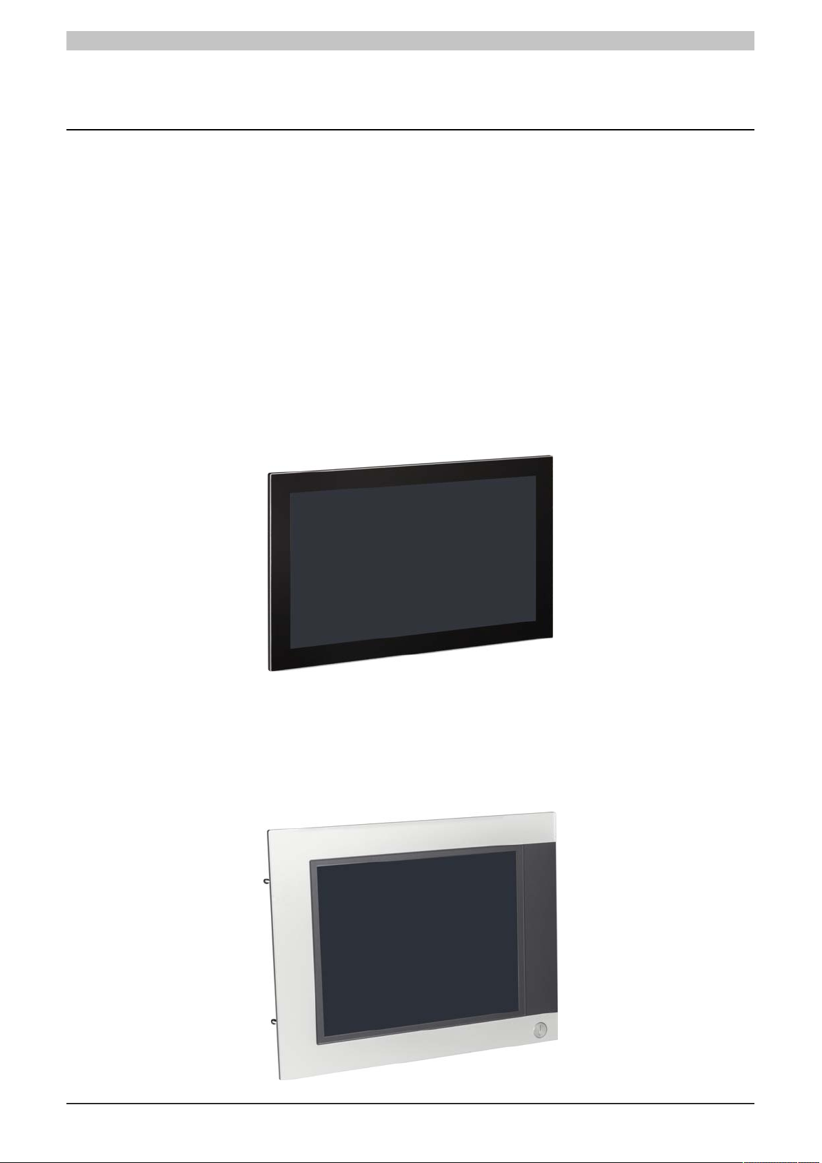
2.1.2.1 AP9x3 panels
AP9x3 panels form the basis for the Automation Panel 9x3, Panel PC 900, Panel PC 2100, Panel PC 2200 and
Panel PC 3100 system families. They consist of a display and touch screen. Different display diagonals and touch
screen technologies are available. The panels can only be operated as a complete system in combination with
a link module (Automation Panel 9x3) or CPU board and system unit (Panel PC 900, Panel PC 2100, Panel PC
2200, Panel PC 3100). The panels are installed using retaining clips.
Single-touch panels start with model number 5AP923.xxxx-xx; multi-touch panels start with model number
5AP933.xxxx-xx.
2.1.2.2 AP1000 panels
AP1000 panels form the basis for the Automation Panel 1000, Panel PC 900, Panel PC 2100, Panel PC 2200 and
Panel PC 3100 system families. Different display diagonals and touch screen technologies as well as panels with
touch screen and keys are available. Panels can only be operated as a complete system in combination with a link
module (Automation Panel 1000) or CPU board and system unit (Panel PC 900, Panel PC 2100, Panel PC 2200,
Panel PC 3100). The panels are installed using retaining clips or clamping blocks.
14 Panel PC 2200 built-in devices User's manual V 1.05 Translation of the original documentation

Technical data
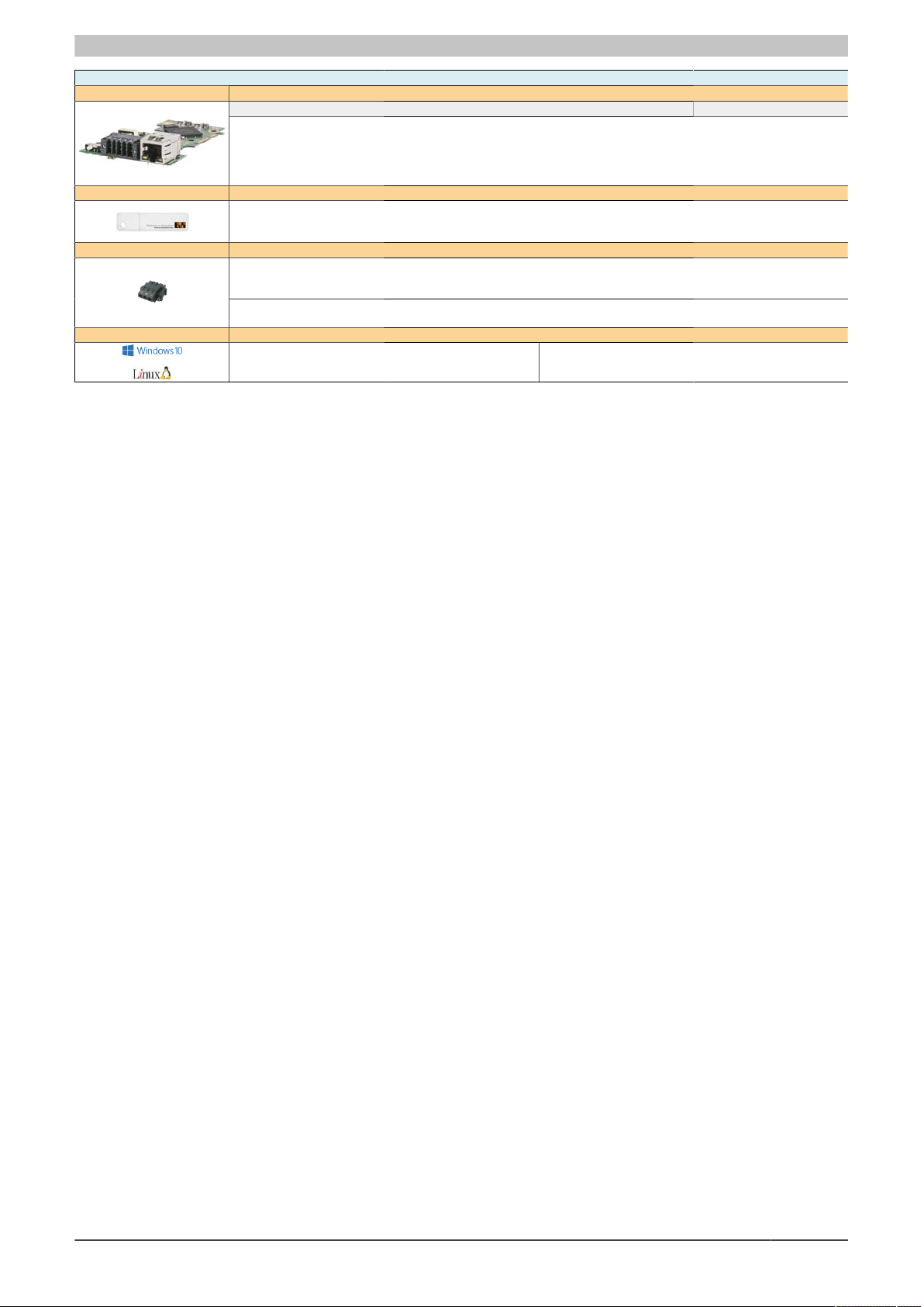
2.1.2.3 System units
System units consist of the CPU board and an aluminum housing. All interfaces and the main memory of the
PPC2200 are integrated on the system units. An interface option and CFast card can also be connected. The main
memory modules are permanently installed on the system unit and cannot be replaced.
If a system unit is installed on a panel, this results in a functional Panel PC 2200.
A system unit without a panel is not functional.
2.1.2.3.1 Features
•
Intel Atom X processor series (Apollo Lake)
•
Up to quad-core CPU performance
•
Powerful graphics (Intel HD graphics)
•
Compact dimensions
•
2x Gigabit Ethernet
•
2x USB 3.0
•
1x CFast slot
•
1x interface option slot
•
Fanless operation
•
Real time clock, RTC (battery-backed)
•
TPM 2.0 security
Panel PC 2200 built-in devices User's manual V 1.05 Translation of the original documentation 15

Technical data
2.1.3 Design/Configuration
It is possible to configure the Automation Panel 9x3, Automation Panel 1000 and Panel PC 2200 system individually
according to the operating conditions and requirements. The Automation Panel 9x3, Automation Panel 1000 or
Panel PC 2200 system is so flexible that an Automation Panel can be converted to a Panel PC or a Panel PC
to an Automation Panel.
2.1.3.1 Configuration
The following individual components are mandatory for operation as a Panel PC 2200:
•
Panel
•
System unit
•
CFast card for the operating system
•
Operating system
Base system - Configuration
Panels Select 1
923 panels
5AP923.1215-00 12.1" XGA Single-touch No Landscape
5AP923.1505-00 15.0" XGA Single-touch No Landscape
5AP923.1906-00 19.0" SXGA Single-touch No Landscape
933 panels
5AP933.156B-00 15.6" HD Multi-touch No Landscape
5AP933.185B-00 18.5" HD Multi-touch No Landscape
5AP933.215C-00 21.5" FHD Multi-touch No Landscape
5AP933.240C-00 24.0" FHD Multi-touch No Landscape
1120 panels
5AP1120.0573-000 5.7" VGA Single-touch No Landscape
5AP1120.0702-000 7.0" WVGA Single-touch No Landscape
5AP1120.101E-000 10.1" WXGA Single-touch No Landscape
5AP1120.1043-000 10.4" VGA Single-touch No Landscape
5AP1120.1214-000 12.1" SVGA Single-touch No Landscape
5AP1120.121E-000 12.1" WXGA Single-touch No Landscape
5AP1120.1505-000 15.0" XGA Single-touch No Landscape
5AP1120.156B-000 15.6" HD Single-touch No Landscape
5AP1120.1906-000 19.0" SXGA Single-touch No Landscape
1130 panels
5AP1130.0702-000 7.0" WVGA Multi-touch No Landscape
5AP1130.101E-000 10.1" WXGA Multi-touch No Landscape
5AP1130.121E-000 12.1" WXGA Multi-touch No Landscape
5AP1130.156C-000 15.6" FHD Multi-touch No Landscape
5AP1130.185C-000 18.5" FHD Multi-touch No Landscape
1151 panels
5AP1151.0573-000 5.7" VGA No Yes Portrait
1180 panels
5AP1180.1043-000 10.4" VGA Single-touch Yes Landscape
5AP1180.1505-000 15.0" XGA Single-touch Yes Landscape
1181 panels
5AP1181.1043-000 10.4" VGA Single-touch Yes Portrait
5AP1181.1505-000 15.0" XGA Single-touch Yes Landscape
1182 panels
5AP1182.1043-000 10.4" VGA Single-touch Yes Landscape
System units Select 1
System unit Processor Processor -
5PPC2200.AL02-000 Intel Atom x5-E3930 1300 MHz 2 LPDDR4 SDRAM 2 GB
5PPC2200.AL04-000 Intel Atom x5-E3930 1300 MHz 2 LPDDR4 SDRAM 4 GB
5PPC2200.AL14-000 Intel Atom x5-E3940 1600 MHz 4 LPDDR4 SDRAM 4 GB
5PPC2200.AL18-000 Intel Atom x5-E3940 1600 MHz 4 LPDDR4 SDRAM 8 GB
Mass storage devices
CFast cards Select 1
5CFAST.2048-00
5CFAST.4096-00
5CFAST.8192-00
5CFAST.016G-00
5CFAST.032G-00
Interfaces
Battery compartment Selected automatically
Diagonal Resolution Touch screen Keys Format
Cores Main memory type Main memory size
Clock frequency
5CFAST.032G-10
5CFAST.064G-10
5CFAST.128G-10
5CFAST-256G-10
1)
5ACCBT01.0000-001
Table 5: PPC2200 configuration - Base system
1) The battery compartment is selected automatically.
16 Panel PC 2200 built-in devices User's manual V 1.05 Translation of the original documentation
Technical data
Accessories and software - Configuration
Interfaces
Accessories Optional selection
Terminal blocks Select 1
Operating systems Select 1
Interface options Optional, select 1
5ACCIF01.FPCC-000
5ACCIF01.FPLS-000
5ACCIF01.FPSC-000
5ACCIF01.FPCS-000
5ACCIF01.ICAN-000
5MMUSB.2048-01
5MMUSB.4096-01
5MMUSB.032G-02
Power supply connectors
0TB103.9
0TB103.91
Terminal block for IF option
0TB1210.3100
Windows 10
5SWW10.0545-MUL
5ACCIF01.FPLK-000
5ACCIF01.FPLS-001
5ACCIF01.FPSC-001
5ACCIF03.CETH-000
B&R Linux 9
5SWLIN.0745-MUL
Table 6: PPC2200 configuration - Accessories and software
Panel PC 2200 built-in devices User's manual V 1.05 Translation of the original documentation 17
Technical data
Z
C
E
D
A
B
GFX
Y
H
2.2 Complete system
2.2.1 Mechanical properties
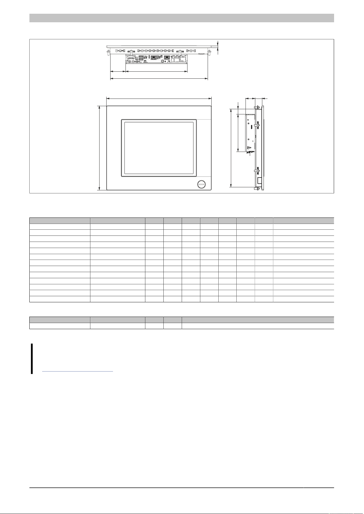
2.2.1.1 Dimensions
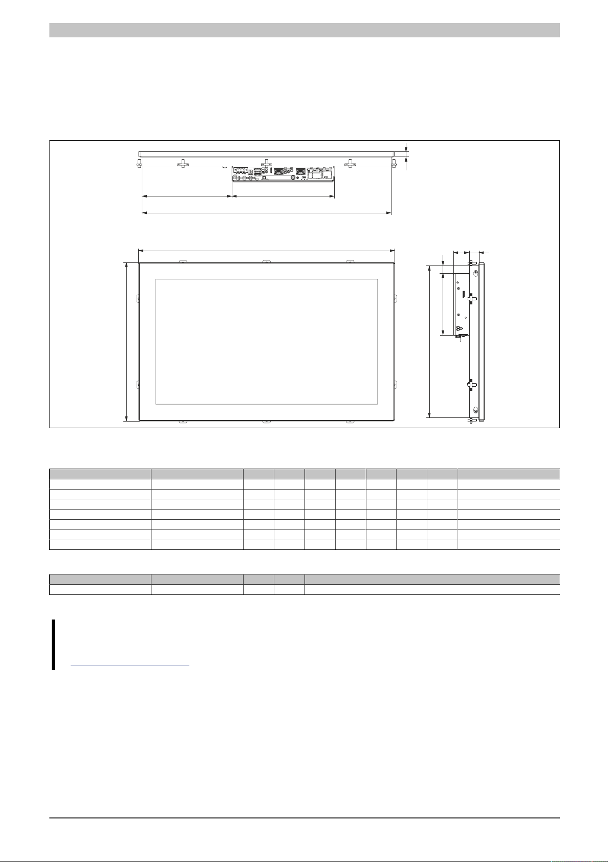
AP9x3 panels - Dimensions
Figure 1: Panel PC 2200 with AP9x3 panels - Dimensions
All dimensions in mm.
Display type Model number A B C D E F G H
12.1" single-touch 5AP923.1215-00 315 239 302 48 9 226 13.5 13.5
15.0" single-touch 5AP923.1505-00 370 288 357 84.5 9 275 14.5 13.5
19.0" single-touch 5AP923.1906-00 440 358 427 149 9 345 23 13.5
15.6" multi-touch 5AP933.156B-00 414 258.5 401 105.5 9 245.5 20 13.5
18.5" multi-touch 5AP933.185B-00 475 295 462 166.5 9 282 18 13.5
21.5" multi-touch 5AP933.215C-00 541.5 333 528.5 199.75 9 320 18 13.5
24.0" multi-touch 5AP933.240C-00 598.5 364 585.5 228.25 9 351 18 13.5
Table 7: AP9x3 panels - Dimensions
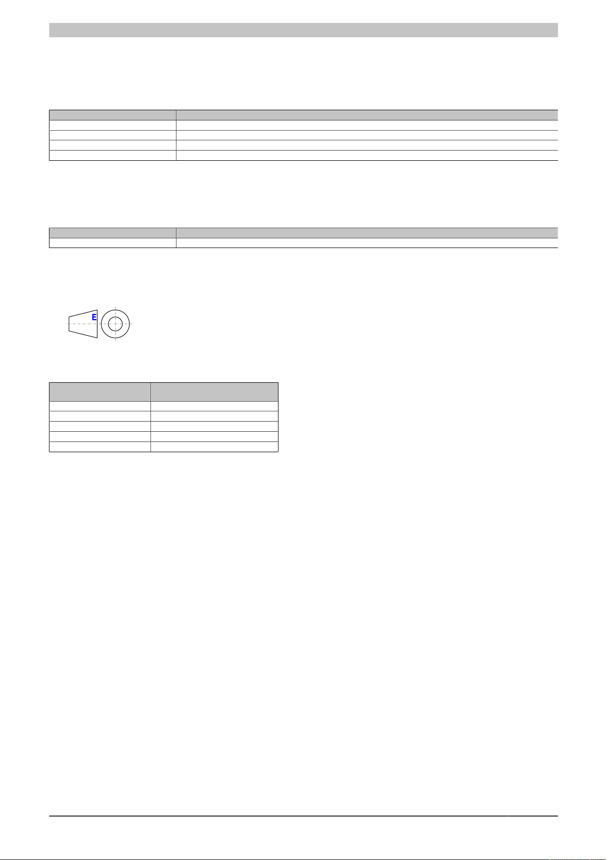
Component Model number X Y Z
System unit 5PPC2200.ALxx-000 29.7 115 190
Table 8: System units - Dimensions
Information:
2D and 3D drawings (DXF and STEP formats) can be downloaded from the B&R website
(www.br-automation.com).
18 Panel PC 2200 built-in devices User's manual V 1.05 Translation of the original documentation
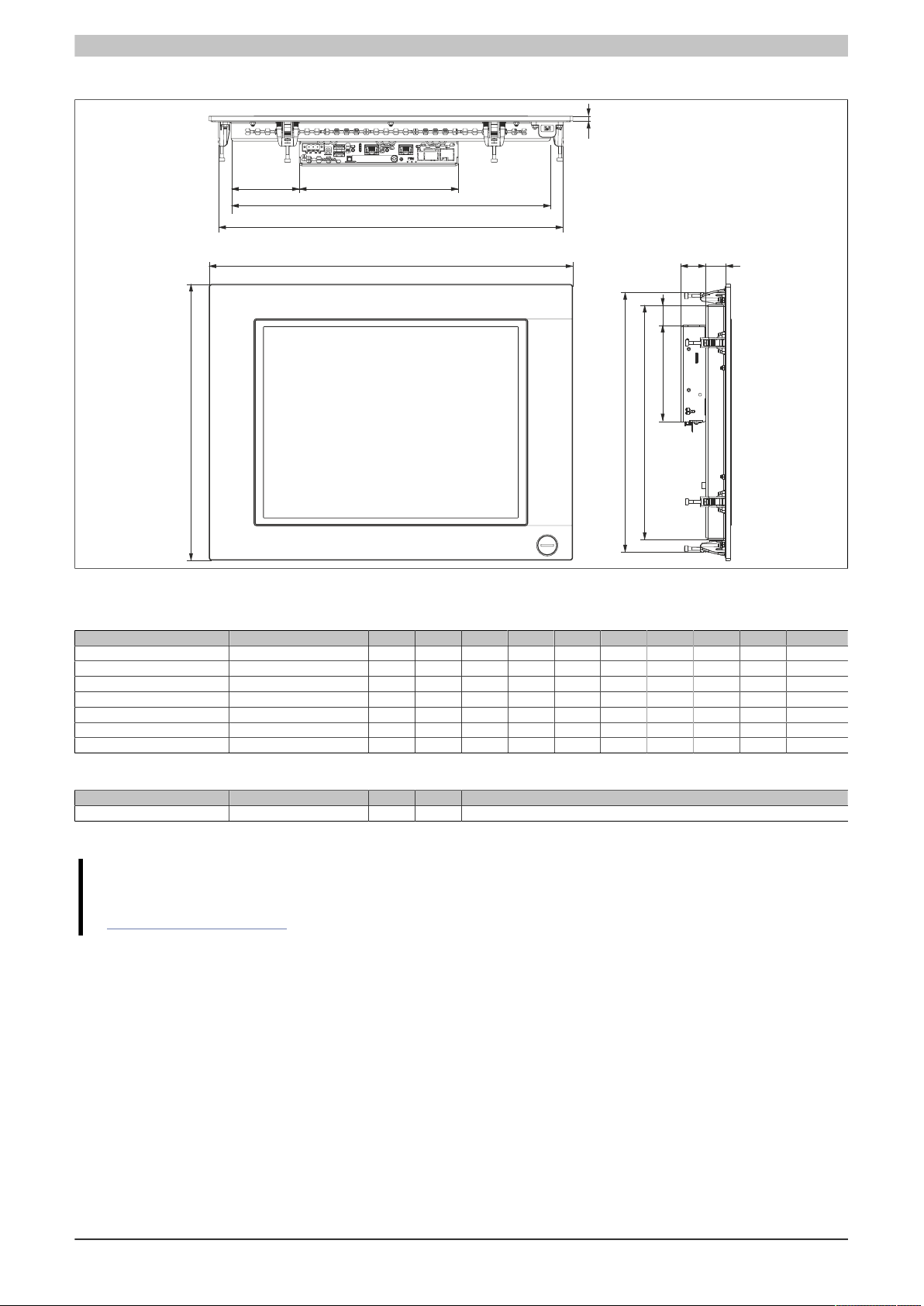
AP1000 panels with retaining clips - Dimensions
A
B
G
C
D
Z
X
H
Y
F
E
Technical data
Figure 2: Panel PC 2200 with AP1000 panels with retaining clips - Dimensions
All dimensions in mm.
Display type Model number A B C D E F G H
5.7" single-touch 5AP1120.0573-000 212 156 196 3 5.7 140 19.5 2.5
5.7" keys 5AP1151.0573-000 212 245 196 3 5.7 229 19.5 2.5
7.0" single-touch 5AP1120.0702-000 212 156 196 3 5.7 140 19.5 2.5
7.0" multi-touch 5AP1130.0702-000 209 153 196 3 9 140 20 7.25
10.1" single-touch 5AP1120.101E-000 279 191 266 38 9 178 18 13.5
10.1" multi-touch 5AP1130.101E-000 279 191 266 38 9 178 18 13.5
10.4" single-touch 5AP1120.1043-000 323 260 300 47.2 5.7 240 21 16
10.4" single-touch with keys 5AP1180.1043-000 323 260 300 47.2 5.7 240 21 16
12.1" single-touch 5AP1120.121E-000 324 221.5 311 60.5 9 208.5 18 13.5
12.1" multi-touch 5AP1130.121E-000 324 221.5 311 60.5 9 208.5 18 13.5
15.6" single-touch 5AP1120.156B-000 414 258.5 401 105.5 9 245.5 20 13.5
15.6" multi-touch 5AP1130.156C-000 414 258.5 401 105.5 9 245.5 20 13.5
18.5" multi-touch 5AP1130.185C-000 475 295 462 166.5 9 282 18 13.5
Table 9: AP1000 panels with retaining clips - Dimensions
Component Model number X Y Z
System unit 5PPC2200.ALxx-000 29.7 115 190
Table 10: System units - Dimensions
Information:
2D and 3D drawings (DXF and STEP formats) can be downloaded from the B&R website
(www.br-automation.com).
Panel PC 2200 built-in devices User's manual V 1.05 Translation of the original documentation 19
Technical data
F
GHX
Y
I
A
B
C
D
Z
E
J
AP1000 panels with clamping blocks - Dimensions
Figure 3: Panel PC 2200 with AP1000 panels with clamping blocks - Dimensions
All dimensions in mm.
Display type Model number A B C D E F G H I J
10.4" single-touch with keys 5AP1181.1043-000 323 358 270 70.5 5.7 305 21.3 17.5 338 300
10.4" single-touch with keys 5AP1182.1043-000 423 288 355.5 70.5 5.7 234 21.3 17.5 268 400
12.1" single-touch 5AP1120.1214-000 362 284 309 52.5 5.7 234 20.3 17.5 264 339
15.0" single-touch 5AP1120.1505-000 435 330 382 81.5 5.7 280 24.3 24 310 412
15.0" single-touch with keys 5AP1180.1505-000 435 330 382 81.5 5.7 280 24.3 24 310 412
15.0" single-touch with keys 5AP1181.1505-000 435 430 382 81.5 5.7 380 24.3 24 410 413
19.0" single-touch 5AP1120.1906-000 527 421 445 186.5 5.7 351 23.3 19.3 401 507
Table 11: AP1000 panels with clamping blocks - Dimensions
Component Model number X Y Z
System unit 5PPC2200.ALxx-000 29.7 115 190
Table 12: System units - Dimensions
Information:
2D and 3D drawings (DXF and STEP formats) can be downloaded from the B&R website
(www.br-automation.com).
20 Panel PC 2200 built-in devices User's manual V 1.05 Translation of the original documentation
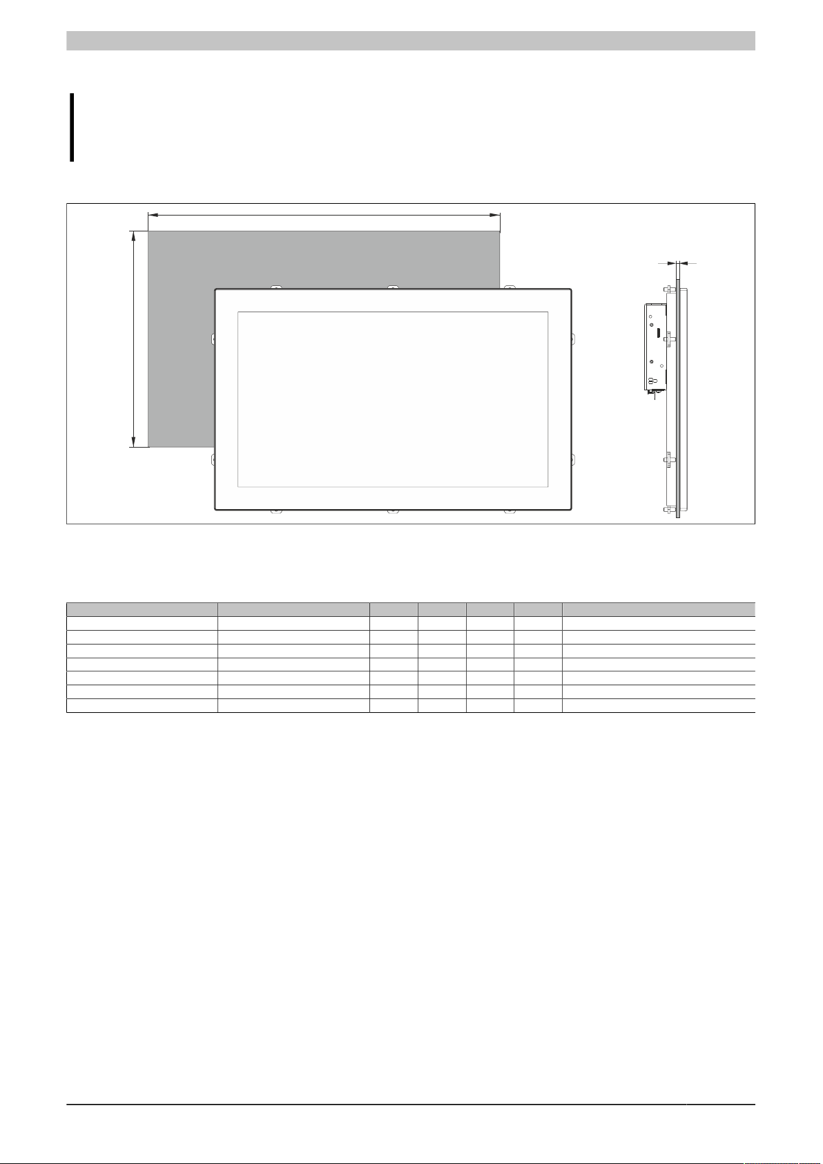
Technical data
Y
X
Z
2.2.1.2 Installation diagrams
Information:
When installing the Panel PC 2200, spacing for air circulation and additional free space for operating
and servicing the device must be taken into account.
AP9x3 panels - Installation diagrams
Figure 4: Panel PC 2200 with AP9x3 panels - Installation diagram
All dimensions in mm.
The cutout tolerances are +0 mm / -0.5 mm.
Display type Model number X Y Z min. Z max. Number of retaining clips
12.1" single-touch 5AP923.1215-00 304 228 1 6 10 pcs.
15.0" single-touch 5AP923.1505-00 359 277 1 6 10 pcs.
19.0" single-touch 5AP923.1906-00 429 347 1 6 12 pcs.
15.6" multi-touch 5AP933.156B-00 403 247.5 1 6 10 pcs.
18.5" multi-touch 5AP933.185B-00 464 284 1 6 10 pcs.
21.5" multi-touch 5AP933.215C-00 530.5 322 1 6 14 pcs.
24.0" multi-touch 5AP933.240C-00 587.5 353 1 6 14 pcs.
Table 13: AP9x3 panels - Installation diagrams
Dimension "Z" describes the thickness of the wall or control cabinet plate.
A hex screwdriver is needed to tighten and remove the screw on the retaining clips. The maximum tightening torque
of the retaining clips is 1 Nm.
Panel PC 2200 built-in devices User's manual V 1.05 Translation of the original documentation 21

Technical data
Y
X
Z
AP1000 panels with retaining clips - Installation diagrams
Figure 5: Panel PC 2200 with AP1000 panels with retaining clips - Installation diagram
All dimensions in mm.
The cutout tolerances are +0 mm / -0.5 mm.
Display type Model number X Y Z min. Z max. Number of retaining clips
5.7" single-touch 5AP1120.0573-000 199 143 1 8 4
5.7" keys 5AP1151.0573-000 199 232 1 8 6
7.0" single-touch 5AP1120.0702-000 199 143 1 8 4
7.0" multi-touch 5AP1130.0702-000 199 143 1 8 4
10.1" single-touch 5AP1120.101E-000 268 180 1 6 8
10.1" multi-touch 5AP1130.101E-000 268 180 1 6 8
10.4" single-touch 5AP1120.1043-000 303 243 1 10 8
10.4" single-touch with keys 5AP1180.1043-000 303 243 1 10 8
12.1" single-touch 5AP1120.121E-000 313 210.5 1 6 10
12.1" multi-touch 5AP1130.121E-000 313 210.5 1 6 10
15.6" single-touch 5AP1120.156B-000 403 247.5 1 6 10
15.6" multi-touch 5AP1130.156C-000 403 247.5 1 6 10
18.5" multi-touch 5AP1130.185C-000 464 284 1 6 10
Table 14: AP1000 panels with retaining clips - Installation diagrams
Dimension "Z" describes the thickness of the wall or control cabinet plate.
A 2.5 mm hex screwdriver is needed to tighten and remove the screw on the retaining clips. The maximum tightening
torque of the retaining clips is 1 Nm.
Information:
A minimum circumferential distance of 30 mm must be maintained in order to enable installation with
retaining clips.
22 Panel PC 2200 built-in devices User's manual V 1.05 Translation of the original documentation
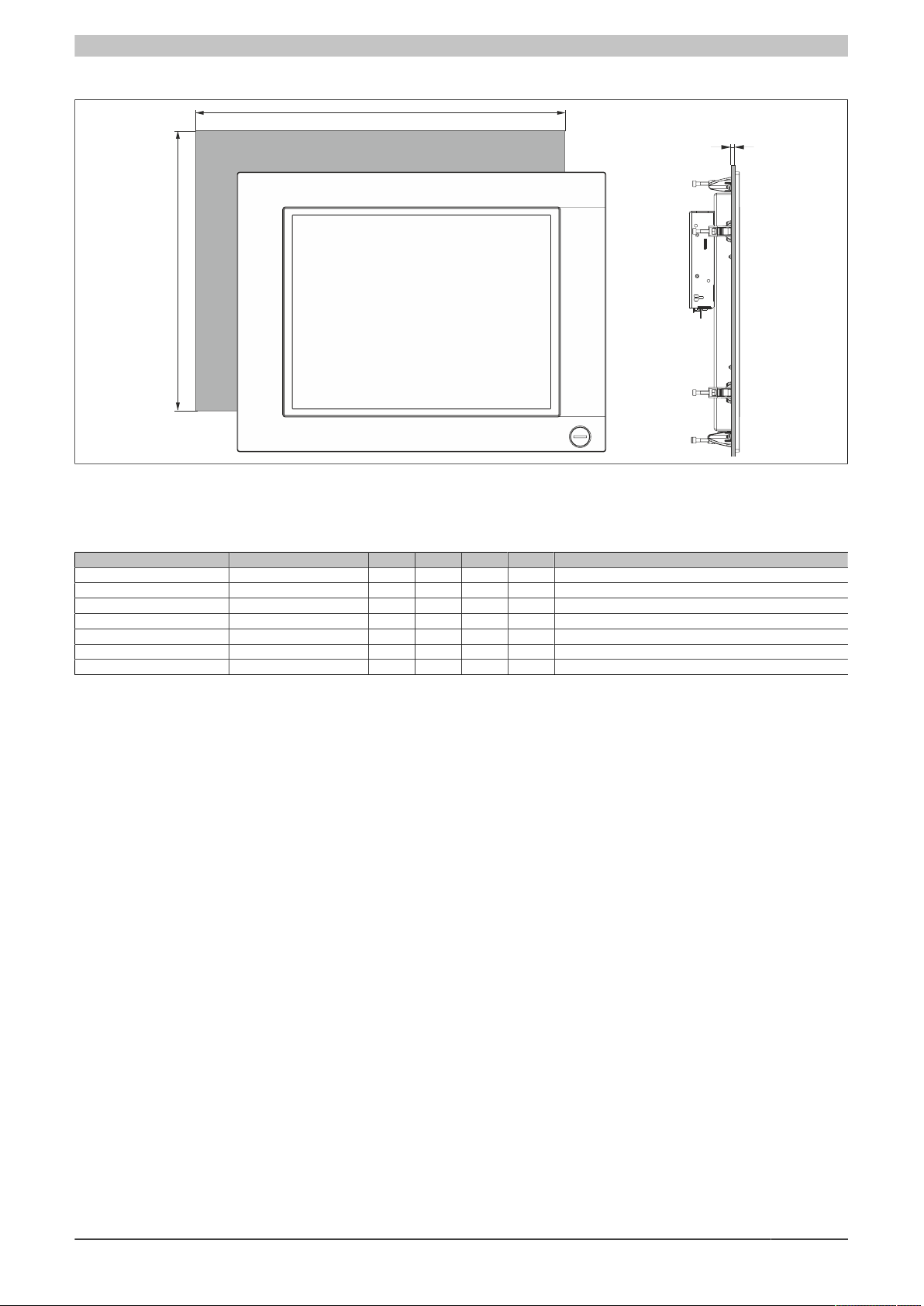
AP1000 panels with clamping blocks - Installation diagrams
Z
Y
X
Figure 6: Panel PC 2200 with AP1000 panels with clamping blocks - Installation diagram
Technical data
All dimensions in mm.
The cutout tolerances are +0 mm / -0.5 mm.
Display type Model number X Y Z min. Z max. Number of clamping blocks
10.4" single-touch with keys 5AP1181.1043-000 303 341 2 10 10
10.4" single-touch with keys 5AP1182.1043-000 403 271 2 10 8
12.1" single-touch 5AP1120.1214-000 342 267 2 10 8
15.0" single-touch 5AP1120.1505-000 415 313 2 10 8
15.0" single-touch with keys 5AP1180.1505-000 415 313 2 10 8
15.0" single-touch with keys 5AP1181.1505-000 415 413 2 10 10
19.0" single-touch 5AP1120.1906-000 510 404 2 10 12
Table 15: AP1000 panels with clamping blocks - Installation diagrams
Dimension "Z" describes the thickness of the wall or control cabinet plate.
A 3 mm hex screwdriver is needed to tighten or remove the screw on the clamping blocks. The maximum tightening
torque of the clamping block is 0.5 Nm.
Panel PC 2200 built-in devices User's manual V 1.05 Translation of the original documentation 23
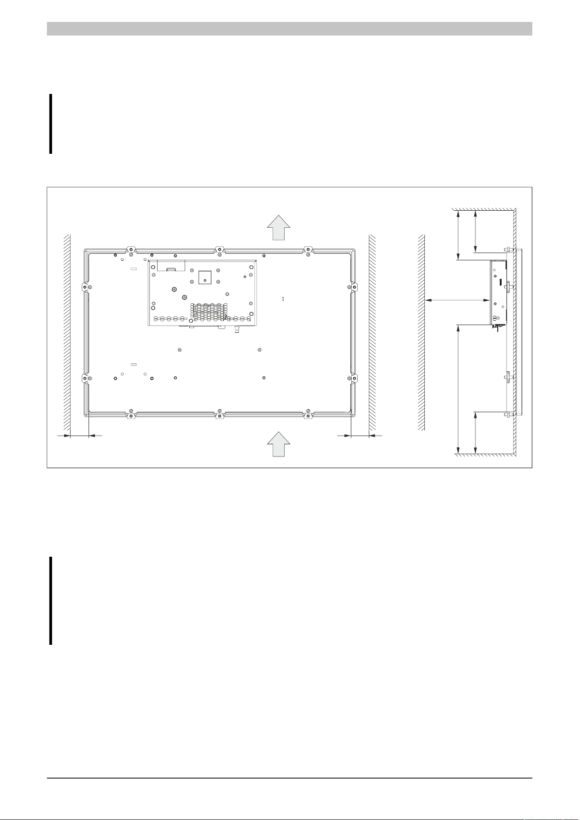
Technical data
Air inlet
Air outlet
S4
Rear view
Side view
S3
S2
S3
S1
S1
S2
2.2.1.3 Spacing for air circulation
To ensure sufficient air circulation, a specified clearance must be provided above, below, to the side and rear of
the unit. For the minimum specified clearance, see the following diagrams. This is valid for all variants.
Information:
The following figure and table exclusively show the thermal view of the complete system. If additional
space is required for operating or servicing the device, this must be taken into account during installation.
The air inlet and air outlet are shown in the following figure. Because the warm air rises from bottom to top, the
air inlet is at the bottom.
Figure 7: Panel PC 2200 - Spacing for air circulation
S1: ≥20 mm
S2: ≥50 mm
S3: ≥100 mm
S4: ≥50 mm
Caution!
The specified spacing for air circulation is based on worst-case operation at the maximum specified
ambient temperature. The maximum specified ambient temperature is not permitted to be exceeded!
If the specified spacing for air circulation cannot be maintained, the maximum specified temperatures
of the temperature sensors (see "Temperature sensor positions" on page 33) must be monitored by
the user and appropriate measures taken if these values are exceeded.
24 Panel PC 2200 built-in devices User's manual V 1.05 Translation of the original documentation
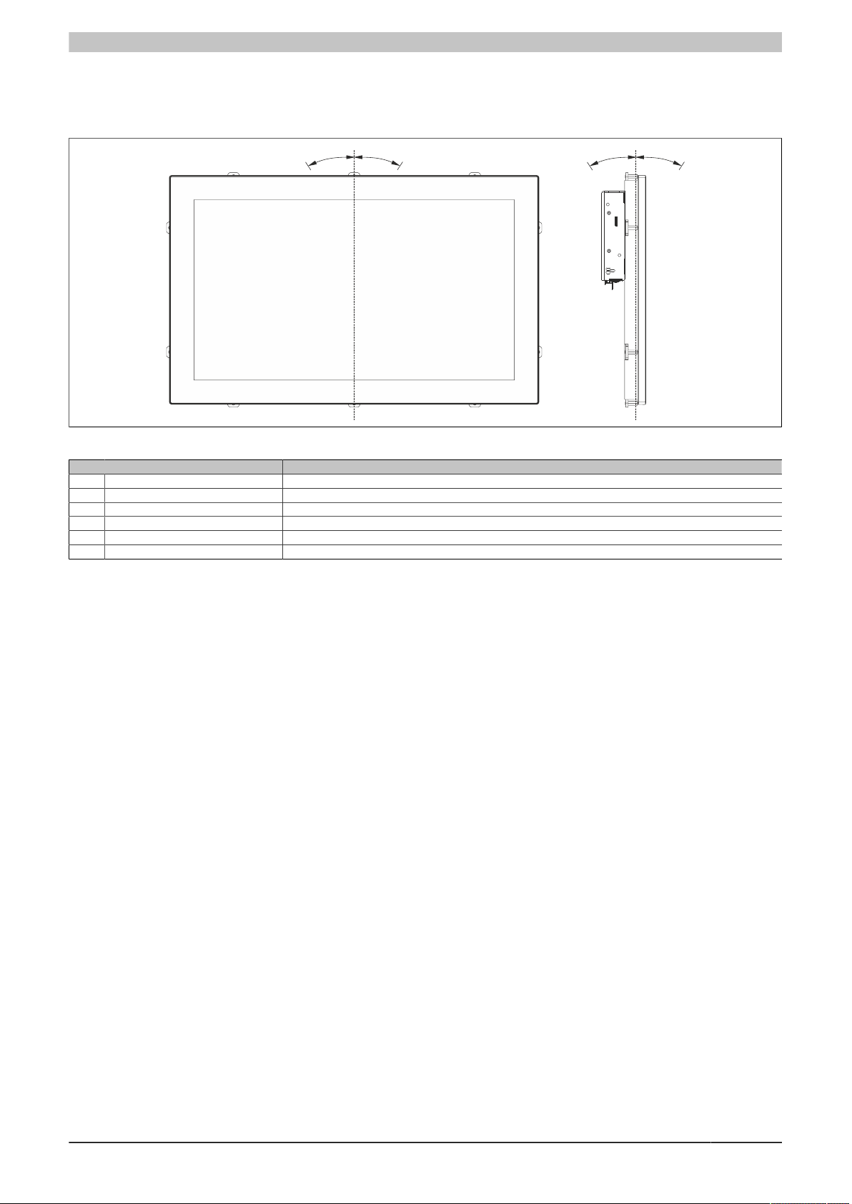
Technical data
A
B
0°
C
D
0°
2.2.1.4 Mounting orientations
The following diagrams show the specified mounting orientations of Panel PC 2200 devices. A PPC2200 is only
permitted to be installed as shown or described below.
Figure 8: Panel PC 2200 - Mounting orientation
Mounting orientation Ambient temperature limitation
0° 0° None
A -1° to -90° (counterclockwise) 5°C
B +1° to +90° (clockwise) 5°C
C, D ±180° (interfaces on top) None
C -1° to 90° 5°C
D +1° to +90° (display facing down) 5°C
Table 16: Mounting orientations during operation
1) The maximum ambient temperature must be reduced by ....
1)
During installation, it is important to make sure that the spacing as described in section "Spacing for air circulation"
on page 24 is observed in order to achieve natural air circulation.
Panel PC 2200 built-in devices User's manual V 1.05 Translation of the original documentation 25
Technical data
2.2.1.5 Weight specifications
Display type Model number Weight [g]
12.1" single-touch 5AP923.1215-00 2200
15.0" single-touch 5AP923.1505-00 3700
19.0" single-touch 5AP923.1906-00 5800
15.6" multi-touch 5AP933.156B-00 3850
18.5" multi-touch 5AP933.185B-00 4850
21.5" multi-touch 5AP933.215C-00 5400
24.0" multi-touch 5AP933.240C-00 7800
Table 17: AP9x3 panels - Weight
Display type Model number Weight [g]
5.7" single-touch 5AP1120.0573-000 1100
5.7" keys 5AP1151.0573-000 1400
7.0" single-touch 5AP1120.0702-000 900
7.0" multi-touch 5AP1130.0702-000 1200
10.1" single-touch 5AP1120.101E-000 1900
10.1" multi-touch 5AP1130.101E-000 2000
10.4" single-touch 5AP1120.1043-000 2800
10.4" single-touch with keys 5AP1180.1043-000 2800
10.4" single-touch with keys 5AP1181.1043-000 3400
10.4" single-touch with keys 5AP1182.1043-000 3500
12.1" single-touch 5AP1120.1214-000 3200
12.1" single-touch 5AP1120.121E-000 2300
12.1" multi-touch 5AP1130.121E-000 2400
15.0" single-touch 5AP1120.1505-000 5000
15.0" single-touch with keys 5AP1180.1505-000 4900
15.0" single-touch with keys 5AP1181.1505-000 6000
15.6" single-touch 5AP1120.156B-000 4200
15.6" multi-touch 5AP1130.156C-000 3700
18.5" multi-touch 5AP1130.185C-000 4600
19.0" single-touch 5AP1120.1906-000 7300
Table 18: AP1000 panels - Weight
Component Model number Weight [g]
System unit 5PPC2200.ALxx-000 577
CFast card
Interface option
5CFAST.xxxx-00 10
5CFAST.xxxx-10 10
5ACCIF01.FPCC-000 25
5ACCIF01.FPCS-000 25
5ACCIF01.FPLK-000 25
5ACCIF01.FPLS-000 25
5ACCIF01.FPLS-001 25
5ACCIF01.FPSC-000 25
5ACCIF01.FPSC-001 25
5ACCIF01.FSS0-000 25
5ACCIF01.ICAN-000 25
5ACCIF03.CETH-000 25
Table 19: System units, CFast cards, interface options - Weight
26 Panel PC 2200 built-in devices User's manual V 1.05 Translation of the original documentation
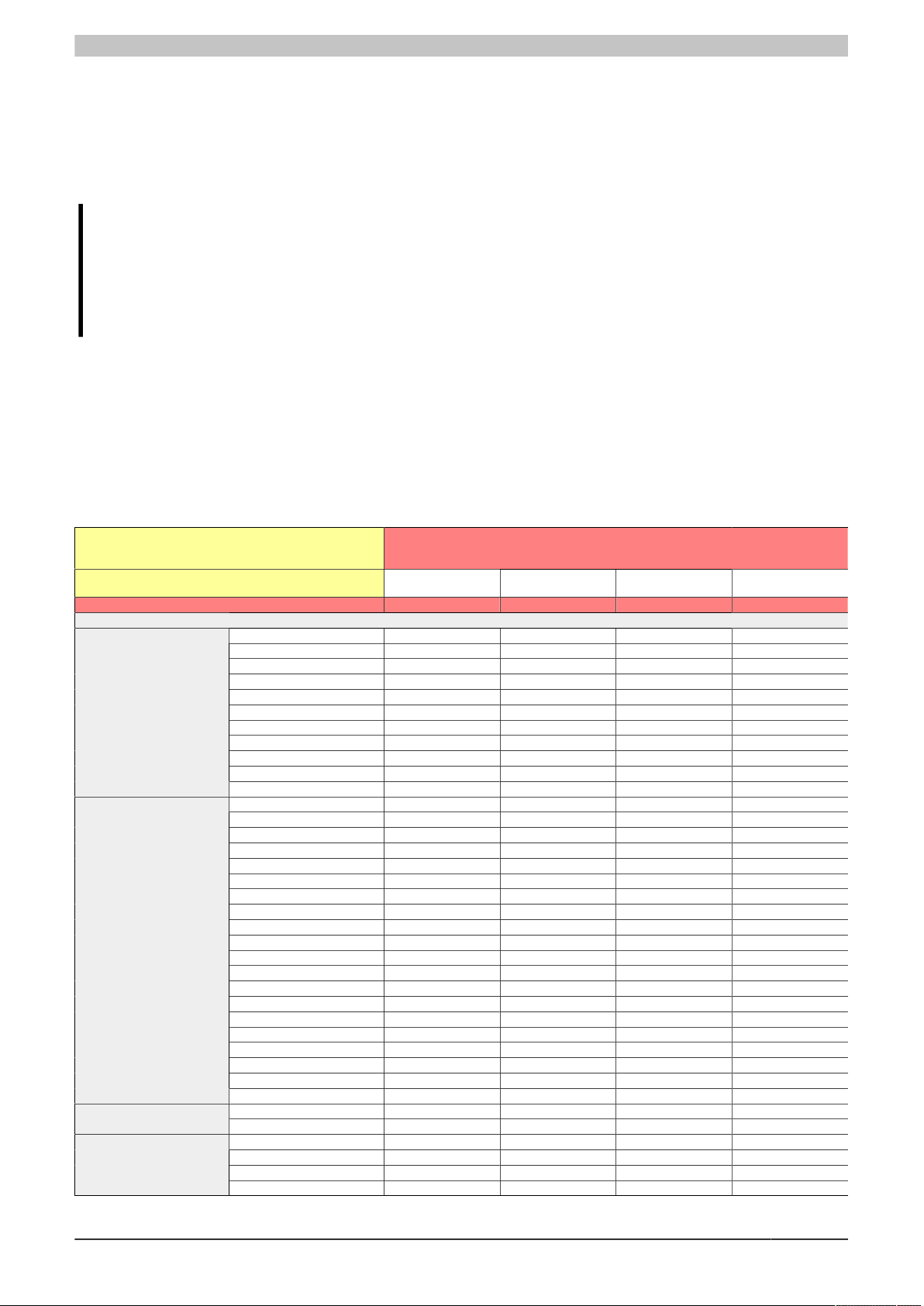
Technical data
2.2.2 Environmental properties
2.2.2.1 Temperature specifications
Because it is possible to combine different system units with different panels, the following tables provide a component-dependent overview of the maximum, minimum and typical possible ambient temperatures resulting from
these combinations.
Information:
The minimum and maximum specified ambient temperatures were determined under worst-case conditions for operation. Experience has shown that higher ambient temperatures can be achieved with
typical applications in Microsoft Windows, for example. The relevant test and assessment must be
carried out individually by the user on site (reading out the temperatures in BIOS or using the B&R
Control Center, for example).
Information about worst-case conditions
•
Power Thermal Utility from Intel for simulating 100% processor utilization
•
BurnInTest tool (BurnInTest V8.1 Pro by PassMark Software) for simulating 100% interface utilization using
loopback adapters (USB interfaces)
•
Maximum expansion and power consumption of the system
•
100% display brightness
2.2.2.1.1 Maximum ambient temperature for worst-case operation
All temperature specifications in degrees Celsius
(°C) at 500 m above sea level, non-condensing
The maximum ambient temperature is typically derated
1°C per 1000 meters starting at 500 m above sea level.
Maximum ambient temperature (accessories)
AP9x3 panels
AP1000 panels
CFast card
Interface option
5AP923.1215-00 ✓ ✓ ✓ ✓
5AP923.1505-00 ✓ ✓ ✓ ✓
5AP923.1906-00 ≤ D0 50 50 ✓ ✓
5AP923.1906-00 ≥ E0 ✓ ✓ ✓ ✓
5AP933.156B-00 ≤ C0 50 50 ✓ ✓
5AP933.156B-00 ≥ D0 ✓ ✓ ✓ ✓
5AP933.185B-00 50 50 ✓ ✓
5AP933.215C-00 ≤ C0 40 40 40 40
5AP933.215C-00 ≥ D0 50 50 ✓ ✓
5AP933.240C-00 ≤ C0 40 40 40 40
5AP933.240C-00 ≥ D0 50 50 ✓ ✓
5AP1120.0573-000 ✓ ✓ ✓ ✓
5AP1151.0573-000 ✓ ✓ ✓ ✓
5AP1120.0702-000 ✓ ✓ ✓ ✓
5AP1130.0702-000 ✓ ✓ ✓ ✓
5AP1120.101E-000 50 50 ✓ ✓
5AP1130.101E-000 50 50 ✓ ✓
5AP1120.1043-000 ✓ ✓ ✓ ✓
5AP1180.1043-000 ✓ ✓ ✓ ✓
5AP1181.1043-000 ✓ ✓ ✓ ✓
5AP1182.1043-000 ✓ ✓ ✓ ✓
5AP1120.1214-000 ✓ ✓ ✓ ✓
5AP1120.121E-000 ✓ ✓ ✓ ✓
5AP1130.121E-000 ✓ ✓ ✓ ✓
5AP1120.1505-000 ✓ ✓ ✓ ✓
5AP1180.1505-000 ✓ ✓ ✓ ✓
5AP1181.1505-000 ✓ ✓ ✓ ✓
5AP1120.156B-000 ✓ ✓ ✓ ✓
5AP1130.156C-000 ✓ ✓ ✓ ✓
5AP1130.185C-000 50 50 ✓ ✓
5AP1120.1906-000 ✓ ✓ ✓ ✓
5CFAST.xxxx-00 ≥ E0 ✓ ✓ ✓ ✓
5CFAST.xxxx-10 ✓ ✓ ✓ ✓
5ACCIF01.ICAN-000 ✓ ✓ ✓ ✓
5ACCIF01.FPCC-000 50 50 45 45
5ACCIF01.FPCS-000 50 50 45 45
5ACCIF01.FPLK-000 50 50 45 45
Table 20: Maximum ambient temperature for worst-case operation
Maximum worst-case ambient temperature (system unit 5PPC2200.ALxx-000)
5PPC2200.AL02-000
(E3930 1.3 GHz)
55 55 50 50
5PPC2200.AL04-000
(E3930 1.3 GHz)
5PPC2200.AL14-000
(E3940 1.6 GHz)
5PPC2200.AL18-000
(E3940 1.6 GHz)
Panel PC 2200 built-in devices User's manual V 1.05 Translation of the original documentation 27
Technical data
5ACCIF01.FPLS-000 50 50 45 45
5ACCIF01.FPLS-001 50 50 45 45
5ACCIF01.FPSC-000 50 50 45 45
5ACCIF01.FPSC-001 50 50 45 45
5ACCIF01.FSS0-000 ✓ ✓ ✓ ✓
5ACCIF03.CETH-000 ✓ ✓ 45 45
Table 20: Maximum ambient temperature for worst-case operation
2.2.2.1.2 Minimum ambient temperature for worst-case operation
All temperature specifications in degrees Celsius
(°C) at 500 m above sea level, non-condensing
Minimum ambient temperature (accessories)
AP9x3 panels
AP1000 panels
CFast card
Interface option
5AP923.1215-00 -20 -20 -20 -20
5AP923.1505-00 -20 -20 -20 -20
5AP923.1906-00 ≤ D0 0 0 0 0
5AP923.1906-00 ≥ E0 -20 -20 -20 -20
5AP933.156B-00 ≤ C0 0 0 0 0
5AP933.156B-00 ≥ D0 -10 -10 -10 -10
5AP933.185B-00 0 0 0 0
5AP933.215C-00 ≤ C0 0 0 0 0
5AP933.215C-00 ≥ D0 0 0 0 0
5AP933.240C-00 ≤ C0 0 0 0 0
5AP933.240C-00 ≥ D0 -10 -10 -10 -10
5AP1120.0573-000 -10 -10 -10 -10
5AP1151.0573-000 0 0 0 0
5AP1120.0702-000 -20 -20 -20 -20
5AP1130.0702-000 -10 -10 -10 -10
5AP1120.101E-000 -20 -20 -20 -20
5AP1130.101E-000 -10 -10 -10 -10
5AP1120.1043-000 -20 -20 -20 -20
5AP1180.1043-000 -20 -20 -20 -20
5AP1181.1043-000 -20 -20 -20 -20
5AP1182.1043-000 -20 -20 -20 -20
5AP1120.1214-000 -20 -20 -20 -20
5AP1120.121E-000 -20 -20 -20 -20
5AP1130.121E-000 -10 -10 -10 -10
5AP1120.1505-000 -20 -20 -20 -20
5AP1180.1505-000 -20 -20 -20 -20
5AP1181.1505-000 -20 -20 -20 -20
5AP1120.156B-000 -20 -20 -20 -20
5AP1130.156C-000 -10 -10 -10 -10
5AP1130.185C-000 -10 -10 -10 -10
5AP1120.1906-000 -20 -20 -20 -20
5CFAST.xxxx-00 ≥ E0 ✓ ✓ ✓ ✓
5CFAST.xxxx-10 ✓ ✓ ✓ ✓
5ACCIF01.ICAN-000 -20 -20 -20 -20
5ACCIF01.FPCC-000 -20 -20 -20 -20
5ACCIF01.FPCS-000 -20 -20 -20 -20
5ACCIF01.FPLK-000 -20 -20 -20 -20
5ACCIF01.FPLS-000 -20 -20 -20 -20
5ACCIF01.FPLS-001 -20 -20 -20 -20
5ACCIF01.FPSC-000 -20 -20 -20 -20
5ACCIF01.FPSC-001 -20 -20 -20 -20
5ACCIF01.FSS0-000 -20 -20 -20 -20
5ACCIF03.CETH-000 -20 -20 -20 -20
Table 21: Minimum ambient temperature for worst-case operation
Minimum worst-case ambient temperature (system unit 5PPC2200.ALxx-000)
5PPC2200.AL02-000
(E3930 1.3 GHz)
-25 -25 -25 -25
5PPC2200.AL04-000
(E3930 1.3 GHz)
5PPC2200.AL14-000
(E3940 1.6 GHz)
5PPC2200.AL18-000
(E3940 1.6 GHz)
28 Panel PC 2200 built-in devices User's manual V 1.05 Translation of the original documentation
2.2.2.1.3 Maximum ambient temperature for typical operation
Information about typical conditions
•
The total power of all USB interfaces on the system unit is limited to 1 W.
•
2x Gigabit Ethernet.
•
No permanent 100% processor utilization and graphics utilization.
•
The power consumption of the complete system is limited to 45 W. For the power consumption of individual
components, see "Power calculation" on page 37.
•
80% display brightness.
Technical data
All temperature specifications in degrees Celsius
(°C) at 500 m above sea level, non-condensing
The maximum ambient temperature is typically derated
1°C per 1000 meters starting at 500 m above sea level.
Maximum ambient temperature for typical operation (accessories)
AP9x3 panels
AP1000 panels
CFast card
Interface option
5AP923.1215-00 ✓ ✓ ✓ ✓
5AP923.1505-00 ✓ ✓ ✓ ✓
5AP923.1906-00 ≤ D0 50 50 50 50
5AP923.1906-00 ≥ E0 ✓ ✓ ✓ ✓
5AP933.156B-00 ≤ C0 50 50 50 50
5AP933.156B-00 ≥ D0 ✓ ✓ ✓ ✓
5AP933.185B-00 50 50 50 50
5AP933.215C-00 ≤ C0 40 40 40 40
5AP933.215C-00 ≥ D0 50 50 50 50
5AP933.240C-00 ≤ C0 40 40 40 40
5AP933.240C-00 ≥ D0 50 50 50 50
5AP1120.0573-000 ✓ ✓ ✓ ✓
5AP1151.0573-000 ✓ ✓ ✓ ✓
5AP1120.0702-000 ✓ ✓ ✓ ✓
5AP1130.0702-000 ✓ ✓ ✓ ✓
5AP1120.101E-000 50 50 50 50
5AP1130.101E-000 50 50 50 50
5AP1120.1043-000 ✓ ✓ ✓ ✓
5AP1180.1043-000 ✓ ✓ ✓ ✓
5AP1181.1043-000 ✓ ✓ ✓ ✓
5AP1182.1043-000 ✓ ✓ ✓ ✓
5AP1120.1214-000 ✓ ✓ ✓ ✓
5AP1120.121E-000 55 55 ✓ ✓
5AP1130.121E-000 55 55 ✓ ✓
5AP1120.1505-000 ✓ ✓ ✓ ✓
5AP1180.1505-000 ✓ ✓ ✓ ✓
5AP1181.1505-000 ✓ ✓ ✓ ✓
5AP1120.156B-000 ✓ ✓ ✓ ✓
5AP1130.156C-000 55 55 ✓ ✓
5AP1130.185C-000 55 55 ✓ ✓
5AP1120.1906-000 ✓ ✓ ✓ ✓
5CFAST.xxxx-00 ≥ E0 ✓ ✓ ✓ ✓
5CFAST.xxxx-10 ✓ ✓ ✓ ✓
5ACCIF01.ICAN-000 ✓ ✓ ✓ ✓
5ACCIF01.FPCC-000 50 50 50 50
5ACCIF01.FPCS-000 50 50 50 50
5ACCIF01.FPLK-000 50 50 50 50
5ACCIF01.FPLS-000 50 50 50 50
5ACCIF01.FPLS-001 50 50 50 50
5ACCIF01.FPSC-000 50 50 50 50
5ACCIF01.FPSC-001 50 50 50
5ACCIF01.FSS0-000 ✓ ✓ ✓ ✓
5ACCIF03.CETH-000 ✓ ✓ 50 50
Maximum ambient temperature for typical operation (system unit 5PPC2200.ALxx-000)
5PPC2200.AL02-000
(E3930 1.3 GHz)
Table 22: Maximum ambient temperature for typical operation
5PPC2200.AL04-000
(E3930 1.3 GHz)
60 60 55 55
5PPC2200.AL14-000
(E3940 1.6 GHz)
5PC2200.AL18-000
(E3940 1.6 GHz)
Panel PC 2200 built-in devices User's manual V 1.05 Translation of the original documentation 29

Technical data
2.2.2.1.4 How are the maximum, minimum and typical ambient temperatures determined?
1. Select the system unit.
2. The columns specify the maximum or minimum temperature in worst-case operation or the maximum temperature in typical operation of the complete system depending on the respective system unit.
Information:
The maximum and typical temperature specifications correspond to a specification at 500 meters
above sea level. The maximum/typical ambient temperature is typically derated 1°C per 1000 meters starting at 500 m above sea level.
3. If interface options and CFast cards are additionally installed in the PPC2200 system, they may result in a
temperature limitation.
4. Possible limitations may arise due to the mounting orientation of the Panel PC 2200. For more information,
see section "Mounting orientations" on page 25.
5. At typical ambient temperatures, the specifications from "Information about typical conditions" on page 29
must be observed. The relevant test and assessment must be carried out individually by the user on site
(reading out the temperatures in BIOS or using the B&R Control Center).
If the installed component has a "✓" (check mark), it can be operated without any problems at the maximum/minimum/typical ambient temperature of the complete system.
If the installed component has a temperature specification, e.g. "45", the ambient temperature of the PPC2200
complete system is not permitted to exceed this value.
30 Panel PC 2200 built-in devices User's manual V 1.05 Translation of the original documentation
 Loading...