

Brilliant Fires Limited SLAB 30, PANORAMA, VISION, SLAB 22, FRAME 30 User, Installation And Servicing Instructions
...Page 1
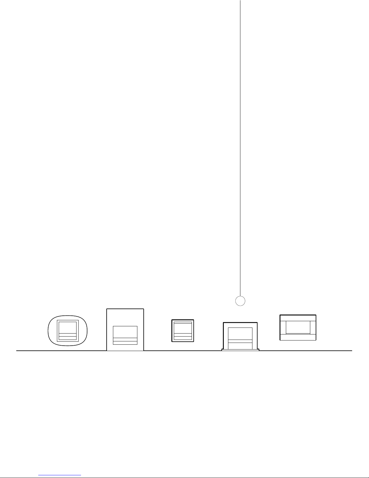
the brilliant SLAB range
USER, INSTALLATION AND SERVICING
INSTRUCTIONS
Please read these instructions before installation and use
Keep this booklet handy for future reference
S
SS
S
SLAB RANGE - LITHIUM BATTERY
Page 2
2
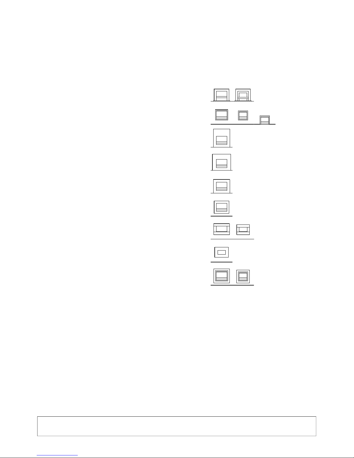
CONTENTS
3
8
13
15
17
17
17
17
19
21
23
24
25
26
27
28
USER’S INSTRUCTIONS
INSTALLER’S INSTRUCTIONS
SLAB 30 & 22
FRAME 30, 22 & 22 INSET
WALL 30
PANORAMA 30
VISION 30
HOLE-IN-WALL 30
LEDGE 30 & 22
STORM 22
GEOMETRY 30 & 22
PLACEMENT OF CERAMICS
PEBBLE
DRIFTWOOD AND CHARCOAL
OUTER CERAMICS
DISH
COMMISIONING AND SERVICING
The appliance names quoted in this booklet are Marketing Names. The Trade Name 113 refers to the 22 and 114 refers to the 30 fires.
The following appliances in the SLAB range are not covered in this booklet.
SLAB 30e, FRAME 30e, WALL e, PANORAMA e, VISION e, HOLE-IN-WALL e, IMAGE, BLOCK, OVAL, PLINTH, SHELF.
Page 3
3
MANUAL CONTROL VERSION
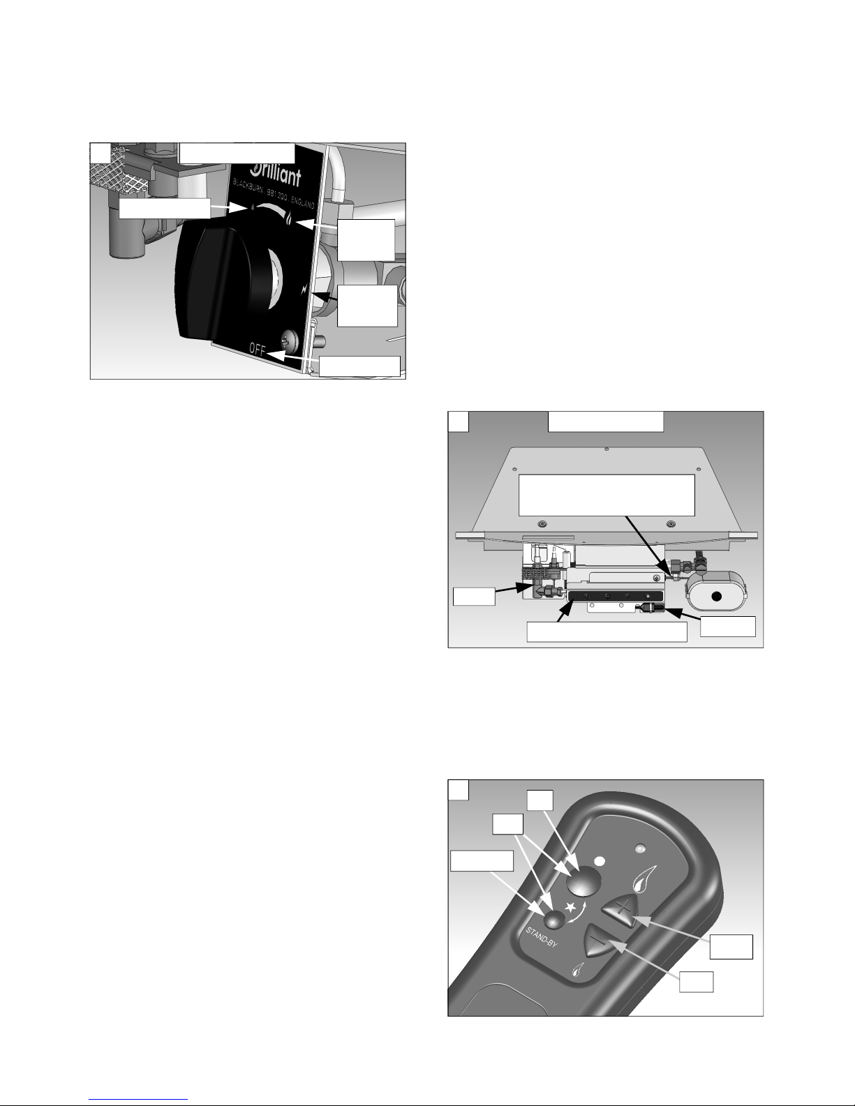
The gas control is situated centrally under the
raised hearth. Piezo ignition is used to light the
pilot, which can also be lit with a match. The
pilot is designed to remain permanently on,
enabling the fire to be lit by simply turning the
gas control on.
TO LIGHT THE PILOT
With the gas control knob in the off position,
fully depress and turn the control knob anticlockwise to the pilot position (spark symbol)
until it clicks, check the pilot has lit (repeat if
the pilot does not light) and keep the control
knob pressed for at least ten seconds When the
control knob is released the pilot should remain
alight. If the pilot does not remain alight repeat
the procedure. If when established the pilot
extinguishes for any reason, the gas supply to
the fire will automatically be cut off by the flame
supervision device. Do not attempt to re-light
the pilot for at least two minutes.
TO LIGHT THE FIRE
With the pilot already lit as above, turn the gas
control knob anti-clockwise to the high setting
(large flame symbol).
TO REDUCE THE HEAT SETTING
Turn the gas control knob anti-clockwise
towards the low setting (small flame symbol).
TO TURN THE FIRE OFF
Depress the gas control knob slightly and turn
clockwise to the pilot position (spark symbol).
The main burner will go out and the pilot will
remain lit and may be left on permanently. To
turn the pilot off, depress the gas control knob
and turn clockwise to OFF.
REMOTE CONTROL VERSION
Please Note: The appliance buttons are an
optional extra and may not be available on your
appliance.
* (not available on LEDGE & STORM)
USER’S INSTRUCTIONS - ALL VERSIONS A
High
position
Pilot
position
1 Manual control
Low position
Off position
On
Off
Stand-by
High
Low
3
2
Sensor
* Appliance buttons (4)
Pilot
Battery Connection
(Except LEDGE & STORM)
Remote control
Page 4
4
TO LIGHT THE FIRE
Point the handset at the sensor on the fire,
situated centrally underneath the raised hearth.
Press and hold the two buttons together on the
left hand side of the handset, when the fire
beeps release the buttons. Alternatively press
the on/off button on the appliance (marked with
a star and dot) until the fire beeps. The fire will
begin the start sequence and the ignition spark
will start clicking. Once the pilot is lit the fire
main burner will light on the high setting. This
whole process will take around 20 seconds.
TO REDUCE THE HEAT SETTING
Point the handset at the sensor on the fire.
Press and hold the minus button (marked with a
small flame). Alternatively press and hold the
minus button on the appliance (marked with a
small flame). When the fire beeps release the
button immediately to turn to the lowest setting
or keep pressing to lower slowly then release
the button at the desired position.
TO INCREASE THE HEAT SETTING
Point the handset at the sensor on the fire.
Press and hold the plus button (marked with a
large flame). Alternatively press and hold the
plus button on the appliance (marked with a
small flame). When the fire beeps release the
button immediately to turn to the lowest setting
or keep pressing to increase slowly then release
the button at the desired position.
TO PUT THE FIRE INTO STANDBY MODE
This setting keeps the pilot lit and turns the
main burner off, allowing the fire to be re-lit
without going through the start up sequence,
saving time and battery power.
NOTE: Standby is not a fully off position and
should only be used for short periods. On
standby the burner may on occasions not fully
turn off and may also remain alight on a very
low setting. This is a normal characteristic of
the control unit.
Point the handset at the sensor on the fire. Push
and hold the small round button (marked with
STAND-BY). Alternatively press and hold the
small button on the appliance (marked with
STAND-BY). When the fire beeps release the
button.
TO TURN THE FIRE OFF
Point the handset at the sensor on the fire.
Press and hold the large round button (marked
with a dot). Alternatively press and hold the on/
off button on the appliance (marked with a star
and dot). When the fire beeps release the
button.
Note:
Note:Note:
Note: When the battery power is low the burner
will sound a repeating double beep every time
you use the fire, please contact your supplier or
Brilliant for a new Lithium battery pack.
Before reporting a fault on your fire ensure the
Before reporting a fault on your fire ensure the Before reporting a fault on your fire ensure the
Before reporting a fault on your fire ensure the
battery is in good condition (i.e. single beep).
battery is in good condition (i.e. single beep).battery is in good condition (i.e. single beep).
battery is in good condition (i.e. single beep).
TO REPLACE THE BATTERIES
The battery situated under the fire is a special
battery and will only be available from your
supplier or from Brilliant. The battery has a
warranty of 6 months from the date of purchase.
To remove, carefully disconnect the battery
lead.
DO NOT
DO NOT DO NOT
DO NOT leave the remote control
handset on or near the fire as damage
may occur.
CAUTION
On Ledge 22, 30 and Storm 22 the
sensor for the remote control is
located at the bottom underside of the
fire surround. DO NOT
DO NOT DO NOT
DO NOT paint over it
when decorating as the fire will fail to
operate correctly.
CAUTION
Page 5

5
When fitting a replacement battery ensure that
it is located as shown in figure A.2 or F.1 if the
appliance is a Ledge.
NOTE: The battery contains a fuse link which
can blow if the wiring is damaged or the cable
terminals are shorted out.
If the handset battery requires replacing it must
be replaced with a new alkaline PP3 or
equivalent.
CLEANING
Cleaning the fire should only be carried out
when the fire is turned off and is cold.
Never use inflammable cleaning fluids.
Never clean the stainless steel with abrasive
cleaning materials such as scouring pads, wire
wool, emery cloth etc. as damage will occur.
CLEANING THE STAINLESS STEEL BOX
We recommend “Hotspot Multi-use Metal
Polish“, available from your supplier or Brilliant.
It is important NOT TO FOLLOW the ‘Directions
For Use’ that are printed on the packaging or
the tube. The correct procedure is as follows:
1. Apply the polish with a clean, soft cloth, to all
three internal sides. DO NOT RUB BRISKLY.
2. It is important that the polish is applied in
the same direction as the brushed finish.
3. Rinse off with a clean soft cloth using a
solution of warm water with two or three
drops of washing up liquid.
4. Repeat the rinsing procedure until all three
surfaces are clean and immediately dry with
a soft cloth to avoid watermarks.
5. Any polish deposits on the Corian® surfaces
can be cleaned with Cif scouring cream.
CLEANING THE CORIAN® MANTLE, HEARTH
AND RAISED HEARTH
For every day cleaning use a damp cloth and
detergent, wipe clean with a clean damp cloth
then a dry cloth. When this does not work use
Cif scouring cream.
TO CLEAN / REPLACE THE CERAMICS
Carefully remove all loose ceramic pieces.
Carefully brush all pieces with a dry soft paint
brush then reassemble by carefully following
the installation instructions and diagrams in
sections J to N.
IMPORTANT NOTES
This fire is CE approved to the European
Standard EN 509 and is intended for decorative
purposes.
Never throw rubbish onto the fire. Never alter
the fuel layout or add extra pieces to the fire.
Never place candles on, in or near the fire as
they are a fire hazard.
During use the ceramics may vary in colour and
as with all high temperature ceramics, cracks
may appear. This is normal and is due to the
initial shrinkage of the ceramics and will not
effect the fire’s performance.
The fire is fitted with an Oxygen Depletion
Sensor (ODS) which continuously monitors the
atmosphere in the room turning off the gas
supply to the fire if combustion products are
detected. If the fire turns itself off, re-light the
fire following the lighting procedure. If the fire
repeatedly turns itself off a qualified service
engineer must be called to check the complete
installation.
Page 6
6
PEBBLE BURNER CERAMICS VERSION
As pebbles are light coloured, any soot
discoloration may be more visible than on the
other available fuel effects.
WARNING
The ODS must not be adjusted or put out of
operation and only original manufacturer’s
replacement parts must be used.
A 100 cm2 air vent must be fitted. If the optional
glass canopy has been fitted a permanent air
vent is not normally required for this fire in the
UK, but a 100 cm2 vent must still be fitted when
used in Southern Ireland. It is important that if
an air vent has been fitted it is periodically
checked to ensure that the vent remains free
from obstruction at all times.
The chimney must be swept before the
appliance is installed and must be checked
regularly to ensure that all products of
combustion are entering the flue and that there
is no excessive build up of soot or debris,
excessive quantities of soot or debris on the fire
will require removal, refer to “CLEANING“. If a
sooting problem persists seek expert advise.
The Slab Frame 30 has a glass canopy
fitted as standard, this canopy must
be replaced with the deeper no airvent glass canopy when an air vent is
not present.
CAUTION
The fire has a naked flame, a suitable
guard should be fitted to give full
protection to the young, elderly or
infirm.
CAUTION
Page 7
7
SPARES & SERVICE
Replacement parts are available from your
supplier or through our mail order service.
Always quote the product code and serial
number when ordering new parts. This
information is on the burner data badge.
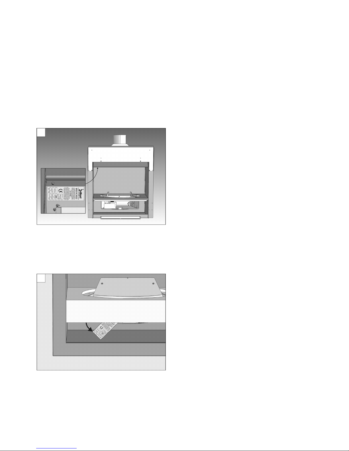
On the LEDGE and STORM the data badge is
stuck onto the roof of the firebox, (see Diagram
A.4).
For all other fires the data badge is situated
beneath the raised hearth in front of the pilot,
lift it over the catch and pivot down, (see figure
A.5).
Only the following components are user
replaceable parts:
All ceramic components.
Control Knob.
Batteries.
The fire must be installed and serviced by a
qualified CORGI registered installation engineer
in accordance with National and Local
Regulations.
Servicing should be carried out at least
annually, but depending upon site conditions
more frequently.
5
4
Page 8

8
INTRODUCTION
This fire is CE approved to the European
Standard EN 509 and is intended for decorative
purposes.
The fire must be installed and serviced by a
qualified CORGI registered installation engineer
in accordance with National and Local
Regulations.
Servicing should be carried out at least
annually, but depending upon site conditions
more frequently.
RELEVANT STANDARDS
Building Regulations Part J
BS 6891: Gas Installation
BS 5440: Part 1 : Flues
BS 5440: Part 2 : Air Supply
BS 5871: Part 1 : Installation of gas appliances
Before installation ensure that the local
distribution conditions (identification of the type
of gas and pressure) and the adjustment of the
appliance are compatible.
The fire is available for either Natural Gas (G20)
or LPG Propane (G31) check the Gas Type on the
burner data badge is correctly marked for your
gas supply.
The fire is fitted with an Oxygen Depletion
Sensor (ODS) which continuously monitors the
atmosphere in the room turning off the gas
supply to the fire if combustion products are
detected. The ODS must not be adjusted or put
out of operation and only original
manufacturer’s replacement parts must be
used.
TECHNICAL INFORMATION
NATURAL GAS (G20)
Heat Input Max (gross): 7.0 kW
Heat Input Min (gross): 4.1 kW
Inlet Pressure: 20 mbar
Injector size (Manual): 504
Injector size (Remote): 494
Number of Injectors: 1
Gas Connection Size: 8mm
Weight: See Packaging
LPG PROPANE (G31)
Heat Input Max (gross): 6.3 kW
Heat Input Min (gross): 5.3 kW
Inlet Pressure: 37 mbar
Injector size: 194
Number of Injectors: 1
Gas Connection Size: 8mm
Weight: See Packaging
SITE REQUIREMENTS
The air supply to the appliance must be in
accordance with National Regulations.
NATURAL FLUE VERSIONS
A 100 cm2 air vent must be fitted. If the optional
no air-vent glass canopy has been fitted a
permanent air vent is not normally required for
this fire in the UK, but a 100 cm2 vent must still
be fitted when used in Southern Ireland. It is
important that if an air vent has been fitted it is
periodically checked to ensure that the vent
remains free from obstruction at all times.
FAN FLUE VERSIONS
When installing any of these appliances a glass
canopy must be fitted and unlike natural flued
versions a 100 sq cm room air vent must be
provided.
INSTALLATION INSTRUCTIONS - ALL VERSIONS B
Page 9

9
BUILDERS OPENING AND HEARTH
The fire must be installed in a non-combustible
builders opening, which must only have an
entrance through the fireplace opening and an
exit via the chimney/flue. All other openings
must be sealed using non-combustible
materials.
To comply with European Regulations the
fireplace must have a non-combustible hearth
not less than 12mm thick. The edge of the
hearth which may be in the form of a raised lip,
must be a minimum of 50mm above the floor
level and must project at least 300mm in front
and 150mm either side of the front edge of the
burner.
However, in England, Wales, Scotland, Northern
and Southern Ireland a hearth is not required if
the appliance is installed so that every part of
any flame or incandescent material will be at
least 225mm above the floor. On our appliances
the lowest flame is that of the pilot.
This equates to the builders opening being a
minimum height above the floor stated in the
table below.
GAS SUPPLY
The gas connection to the fire must be in 8mm
copper pipe not more than 1.5 metres long and
in accordance with National Regulations. Any
additional pipework must be of a diameter to
ensure adequate pressure at the fire. Note: The
end of the pipe must be covered to ensure that
debris cannot enter the pipe when being passed
through masonry.
An isolation valve (supplied) must be fitted
adjacent to the burner, which when closed,
allows the fire to be disconnected for
maintenance or repair in accordance with
National Regulations.
FLUE
The chimney/flue may be class 1 or 2 and must
have a height of at least 3m with an internal
diameter of not less than 125mm. Any damper
or register plate must be removed or locked
open. When fitted to a 125mm flue the fire must
have the no air-vent glass canopy fitted.
The chimney/flue must be sound, free from
obstruction, have a positive updraught and
swept before the appliance is installed. A flue
test in accordance with national regulations
must be carried out.
‡
Minimum height to comply with the regulations regarding the provision of a non-combustible hearth where a hearth is not fitted.
Width
780
780780
780----810
810810
810 580
580580
580----810
810810
810 783
783783
783----810
810810
810 580
580580
580----610
610610
610 783
783783
783----810
810810
810 783
783783
783----810
810810
810 783
783783
783----810
810810
810 783
783783
783----810
810810
810 783
783783
783----810
810810
810 580
580580
580----610
610610
610 580
580580
580----610
610610
610
Height
810
810810
810----845
845845
845 660
660660
660----845
845845
845 668
668668
668----690
690690
690 565
565565
565----590
590590
590 668
668668
668----690
690690
690 668
668668
668----690
690690
690 668
668668
668----690
690690
690 668
668668
668----690
690690
690 668
668668
668----690
690690
690 565
565565
565----590
590590
590 565
565565
565----590
590590
590
Minimum depth
310
310310
310 310
310310
310 310
310310
310 310
310310
310 310
310310
310 310
310310
310 310
310310
310 310
310310
310 310
310310
310 310
310310
310 310
310310
310
Floor to opening
----
25 min
25 min25 min
25 min
‡‡‡‡
70 min
70 min70 min
70 min
‡‡‡‡
70 min
70 min70 min
70 min
‡‡‡‡
200
200200
200
200
200200
200
200
200200
200 150 min
150 min150 min
150 min
‡‡‡‡
70 min
70 min70 min
70 min
‡‡‡‡
70 min
70 min70 min
70 min
‡‡‡‡
70 min
70 min70 min
70 min
‡‡‡‡
Fireplace opening sizes
SLAB 30
SLAB 22
FRAME 30
FRAME 22
& INSET
WALL
PANORAMA
VISION
HOLE-IN-WALL
LEDGE 30
STORM 22
LEDGE 22
Page 10
10
An optional flue gather with a 125mm spigot is
available to enable direct connection to a
125mm flue liner or using an appliance
connector can be connected to a 125mm metal
flue system.
The flue gather can either be connected to the
flue then attached to the box from inside, or it
can be fitted from inside once the box has been
fitted.
A pre-cast concrete gas flue block system to BS
1289 Pt. 1 and Building Regulations Part J can
be used (subject to suitability of the starter
block).
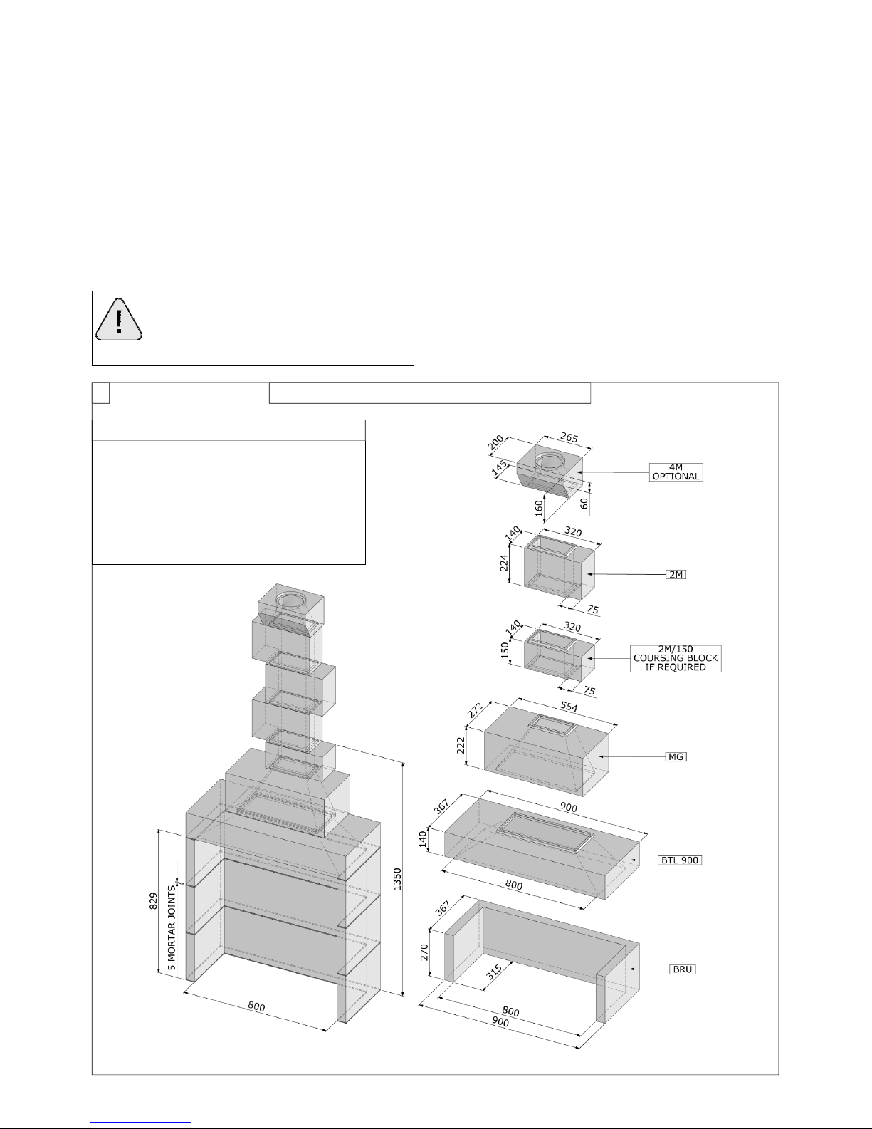
Brilliant and Dunbrik (www.dunbrik.co.uk) have
collaborated to create a larger starter block set
specifically for the Slab 22 / 30 to fit their Class
2 pre-cast flue block system, as shown in
diagram B.1.
1
Note: The 2M/150 coursing block is used to maintain a vertical block coursing height.
DUNBRIK BRILLIANT SLAB STARTER UNIT
KEY
4M
2M
2M/150
MG
BTL900
BRU
Top Exit Block (Optional)
Standard Flue Block
Coursing Block (If Required)
Gather Block
Brilliant Slab Top Lintel
Brilliant Slab Recess Unit
The gather MUST
MUST MUST
MUST be screwed to the
firebox from INSIDE
INSIDE INSIDE
INSIDE to allow removal
of the firebox during servicing.
CAUTION
Page 11
11
GLASS CANOPIES
If an appliance has been factory specified with a
glass canopy, the glass canopy must be fitted
when installing the appliance. Failure to fit the
glass canopy will result in damage to the fire
surround. This is because the glass canopy is
fixed to the standard heat shield. To use the
appliance without fitting the factory specified
glass canopy a standard heat shield must be
obtained and fitted in its place.
Note: The gather must only be used with the
appropriate No air-Vent (NV) glass canopy. An
NV canopy must be fitted if the flue diameter is
less than 175mm. The Slab Frame 30 has a
glass canopy fitted as standard, this canopy
must be replaced with the deeper NV glass
canopy when an air vent is not present.
All supplied glass canopies are supplied in
protective packaging and are secured to the top
of the firebox. This is to prevent any damage to
the glass whilst in transit. The three fixing
screws are packed attached to the canopy.
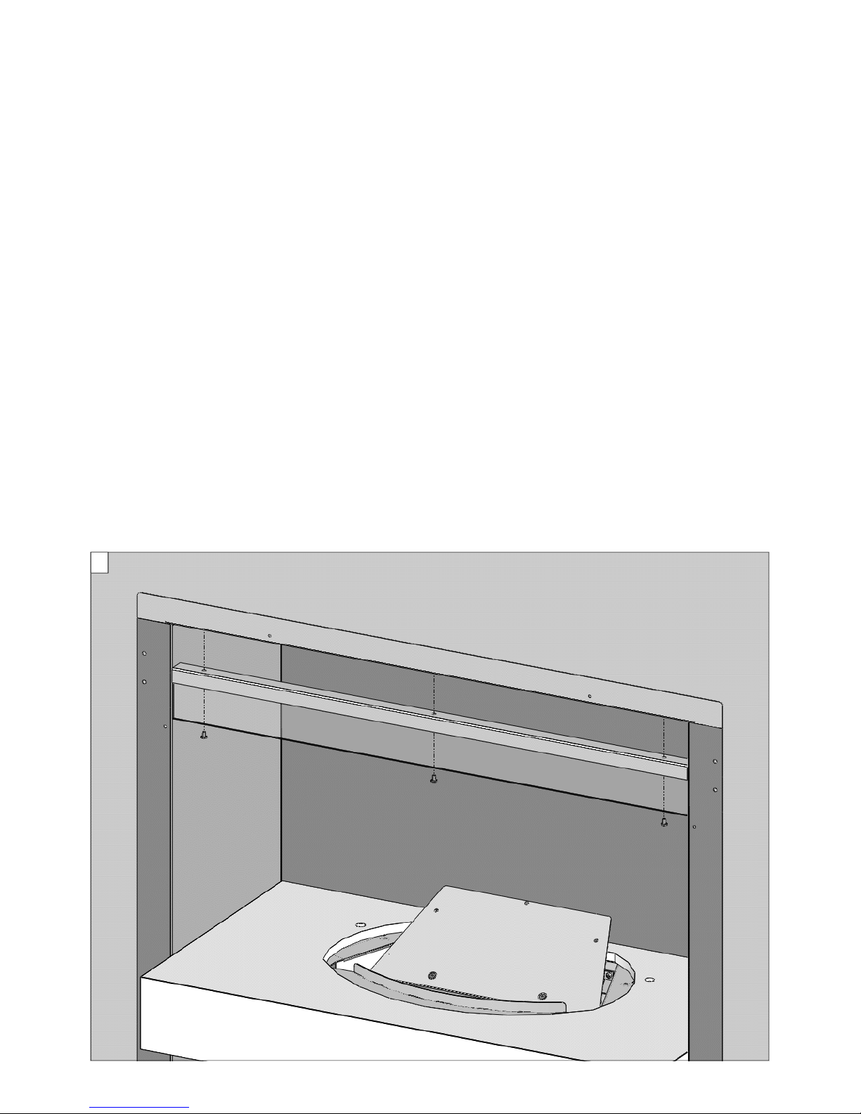
To fit the canopy, first partially remove the
protective plastic covering from the firebox
where it would be trapped by the canopy. Screw
the canopy in place using the three fixing
screws provided (see diagram B.2).
On the following page is a table showing the
appliance variations and the required canopies.
2
Page 12
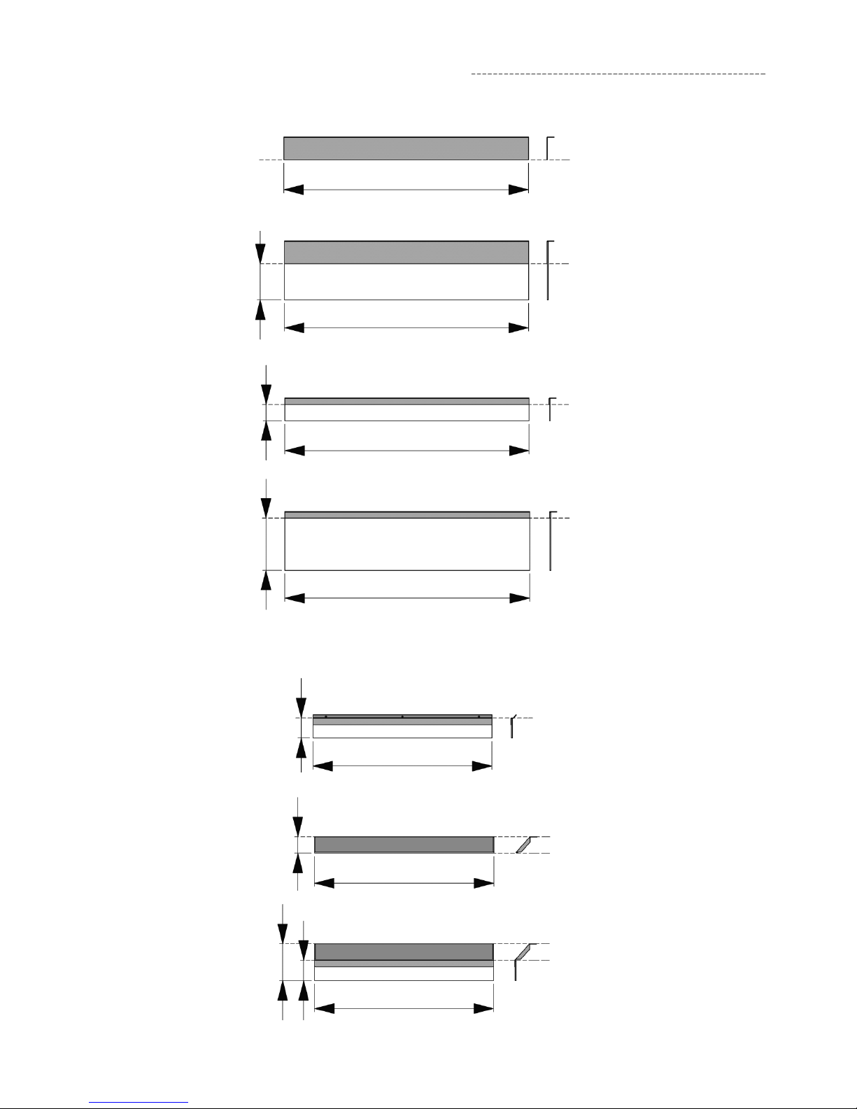
12
749
110
SLAB 30 NV
LEDGE 30 NV
WALL NV
PANORAMA NV
VISION NV
HOLE-IN-WALL NV
Steel not visible
Glass visible
549
62
SLAB 22 NV
Stainless Steel visible
Glass visible
749
50
FRAME 30 STD
GEOMETRY 30 STD
Steel visible
Glass visible
NONE
SLAB 22 STD
Integrated canopy
CANOPY OPTIONS
749
160
FRAME 30 NV
GEOMETRY 30 NV
Steel not visible
Glass visible
749
Steel not visible
SLAB 30 STD
LEDGE 30 STD
CANOPY NOT VISIBLE ABOVE THIS LINE
CANOPY VISIBLE BELOW THIS LINE
549
50
FRAME 22 STD
LEDGE 22 STD*
STORM 22 STD*
GEOMETRY 22 STD
Stainless Steel visible
*Stainless Steel not visible
*
STD = Standard canopy for installations with an air vent. NV = No Vent canopy for installations without an air vent.
549
112
FRAME 22 NV
LEDGE 22 NV†
STORM 22 NV†
GEOMETRY 22 NV
Stainless Steel visible
Glass visible
62
†
†
Page 13
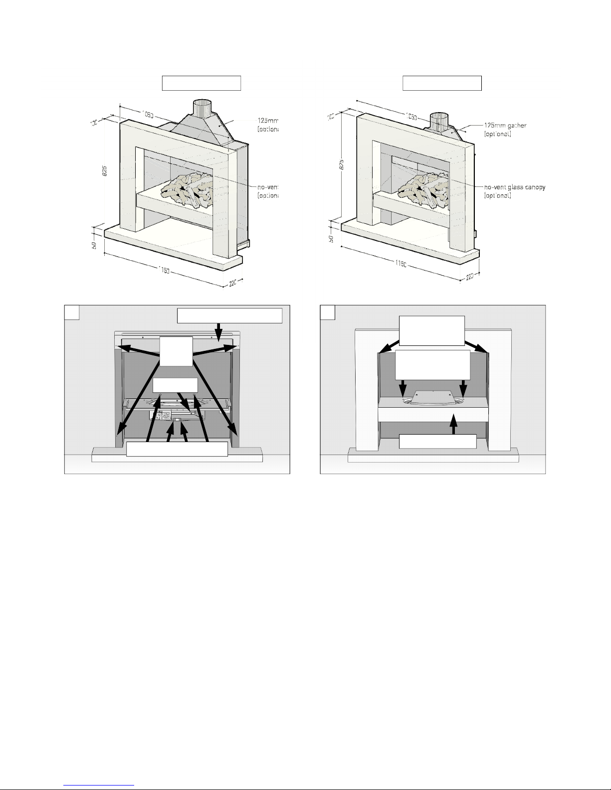
13
The mantle fixing bracket is screwed to the top
of the box in its correct position and does not
need to be removed.
Remove the four screws that secure the burner
to the box, two at the base of the front leg and
two at the top of the rear sloping plate. Separate
the burner from the box (see diagram C.1).
Remove the two countersunk screws securing
the raised hearth to the shelf, carefully remove
the raised hearth and place to one side (see
diagram C.2).
Level the floor beneath the hearth. Fit the
hearth ensuring it is central, level left to right
and perpendicular to the wall.
Prepare the gas supply noting the entry point in
the rear of the box. Slacken the screws in the
gas inlet closure plate and remove. Offer the
box into the fireplace opening, mark the
positions of the four fixing holes in the outer
frame. Remove the box, drill and plug the fixing
holes using the plugs provided (see diagram
C.1).
Partially peel the protective plastic coating away
from the metal box anywhere it may become
trapped.
Apply a thin bead of silicon sealant around the
rear edge of the box flange. Insert the gas pipe
through the pipe entry opening and insert the
box fully into the fireplace opening. Secure to
INSTALLATION - SLAB 30, SLAB 22 C
SLAB 30 SLAB 22
Raised Hearth
2
Raised Hearth
Fixing Points
Mantle Fixing
Holes
1
Gas Inlet
Fixing
Holes
Mantle Fixing Bracket
Burner Fixing Points
Page 14

14
the fireplace opening using the screws provided.
Refit the inlet closure plate.
Slide the raised hearth onto the raised hearth
metal shelf and lightly secure with the two
countersunk screws removed previously (see
diagram C.2).
GAS CONNECTION
MANUAL CONTROL VERSION
Cut a 70mm length of copper pipe and attach it
to the isolating tap supplied. Position the pipe/
isolating tap in line with the slot in the burner
recess bracket. Shape and cut the gas supply
pipe and ensuring the gas supply pipe is clean
internally connect to the isolating tap. Refit the
burner and connect the gas supply. Secure with
the four screws (see diagrams C.1 and C.2).
AUTO REMOTE CONTROL VERSION
Note the position of the isolating tap and
disconnect it. Shape and cut the gas supply pipe
and ensuring the gas supply pipe is clean
internally connect to the isolating tap. Refit the
burner and connect the gas supply. Secure with
the four screws and connect the battery (see
diagrams C.1and A.2).
FITTING THE MANTLE
Remove all the remaining protective plastic
coating from the firebox.
Offer the mantle up to the mantle fixing bracket,
(see diagram C.1). It should stand on the hearth
and push back against the wall over the mantle
fixing bracket.
Secure in position through the mantle with the
two screws and washers provided (see diagram
C.2).
Ensure the firebox is properly sealed
and fixed to the fireplace opening. If
not properly sealed to the wall, the
mantle may overheat resulting in
damage to the mantle.
CAUTION
Page 15
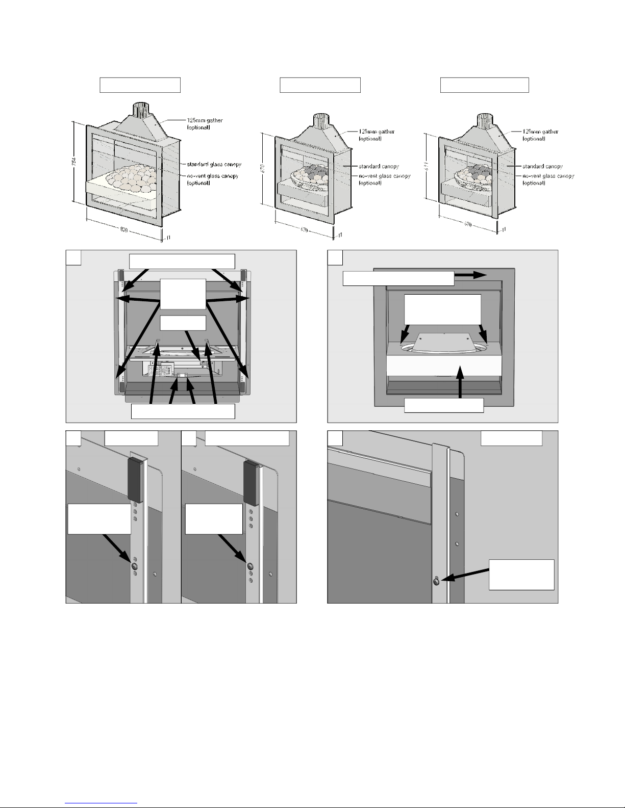
15
Remove the four screws that secure the burner
to the box, two at the base of the front leg and
two at the top of the rear sloping plate. Separate
the burner from the box (see diagram. D.1).
Remove the two countersunk screws securing
the raised hearth to the shelf, carefully remove
the raised hearth and place to one side (see
diagram D.2).
Prepare the gas supply noting the entry point in
the rear of the box. Slacken the screws in the
gas inlet closure plate and remove. Offer the
box into the fireplace opening.
Ensuring the fire is level left to right, mark the
positions of the four fixing holes in the outer
frame. Remove the box, drill and plug the fixing
holes (see diagram D.1)
FRAME 30 FRAME 22
1
Fixing
Holes
Frame Locator strips
Gas Inlet
Burner Fixing Points
FRAME 22 INSET
2
Raised Hearth
Raised Hearth
Fixing Points
Stainless Steel Frame
3a
FRAME 22
3b
FRAME 22 INSET
Use CENTRE
CENTRE CENTRE
CENTRE
Holes
Use TOP
TOP TOP
TOP
Holes
4
Use BOTTOM
BOTTOM BOTTOM
BOTTOM
Holes
FRAME 30
INSTALLATION - FRAME 30, FRAME 22 D
Page 16

16
Partially peel the protective plastic coating away
from the metal box anywhere it may become
trapped.
Apply a thin bead of silicon sealant around the
rear edge of the box flange. Insert the gas pipe
through the pipe entry opening and insert the
box fully into the fireplace opening. Refit the
inlet closure plate.
Secure the box to the fireplace opening using
the four screws provided.
The frame locator strips are fitted to the firebox
at the factory and will not require adjustment. If
the strips have been removed then refitting
them should be done as follows:
Frame 22 - 4 Sided Frame (Diagram D.3a).
Frame 22 - 3 Sided Frame (Diagram D.3b).
Frame 30 - 4 Sided Frame (Diagram D.4).
Slide the raised hearth onto the raised hearth
metal shelf and lightly secure with the two
countersunk screws removed previously (see
diagram D.2).
GAS CONNECTION
MANUAL CONTROL VERSION
Cut a 70mm length of copper pipe and attach it
to the isolating tap supplied. Position the pipe/
isolating tap in line with the slot in the burner
recess bracket. Shape and cut the gas supply
pipe and ensuring the gas supply pipe is clean
internally connect to the isolating tap. Refit the
burner and connect the gas supply. Secure with
the four screws (see diagram D.1).
AUTO REMOTE CONTROL VERSION
Note the position of the isolating tap and
disconnect it. Shape and cut the gas supply pipe
and ensuring the gas supply pipe is clean
internally connect to the isolating tap. Refit the
burner and connect the gas supply. Secure with
the three screws and connect the battery (see
diagrams D.1 and A.2).
FITTING THE FRAME
Place the four magnets at the top and bottom of
each frame locator strip and fit the stainless
steel frame to the box (see diagram D.2).
Remove all the remaining protective plastic
coating from the firebox and frame.
Page 17
17
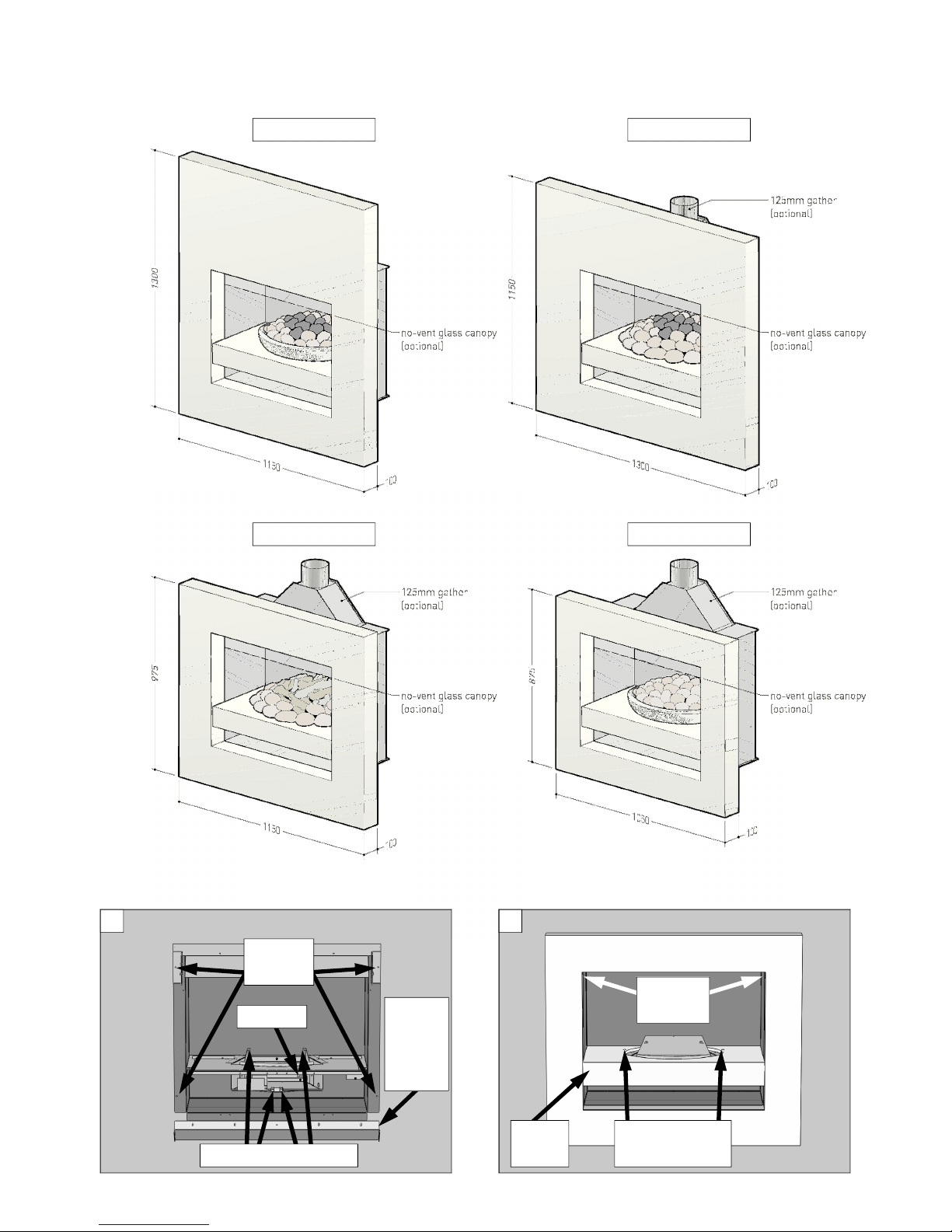
INSTALLATION - WALL, PANORAMA, VISION, HOLE-IN-WALL E
PANORAMA
HOLE-IN WALL
WALL
VISION
1
Fixing
Holes
H.I.W.
Mantle
Hanging
Bracket
Gas Inlet
Burner Fixing Points
2
Securing
Screws
Raised
Hearth
Raised Hearth
Fixing Points
Page 18
18
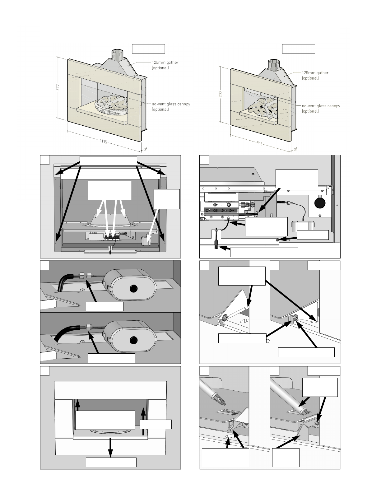
The mantle fixing bracket is screwed to the top
of the box in its correct position and does not
need to be removed. Remove the four screws
that secure the burner to the box, two at the
base of the front leg and two at the top of the
rear sloping plate. Separate the burner from the
box (see diagram E.1).
Remove the two countersunk screws securing
the raised hearth to the shelf, carefully remove
the raised hearth and place to one side (see
diagram E.1).
Prepare the gas supply noting the entry point in
the rear of the box. Slacken the screws in the
gas inlet closure plate and remove. Offer the
box into the fireplace opening.
Ensuring the fire is level left to right, mark the
positions of the four fixing holes in the outer
frame. Remove the box, drill and plug the fixing
holes (see diagram E.1)
Partially peel the protective plastic coating away
from the metal box anywhere it may become
trapped.
Apply a thin bead of silicon sealant around the
rear edge of the box flange. Insert the gas pipe
through the pipe entry opening and insert the
box fully into the fireplace opening. Secure the
box to the fireplace opening using the four fixing
screws provided (see diagram E.1). Refit the
inlet closure plate.
SLAB H.I.W. VERSION ONLY
Position the H.I.W. Mantle Hanging Bracket
(supplied) centrally touching the bottom edge of
the firebox flange, (see Diagram E.1), with the
holes against the wall and the protruding face
pointing upwards. Mark the 5 fixing holes,
remove the bracket, drill and plug the holes
with the Rawl
®
plugs provided, fix the bracket to
the wall using the screws provided.
Slide the raised hearth onto the raised hearth
metal shelf and lightly secure with the two
countersunk screws removed previously (see
diagram E.1).
GAS CONNECTION
MANUAL CONTROL VERSION
Cut a 70mm length of copper pipe and attach it
to the isolating tap supplied. Position the pipe/
isolating tap in line with the slot in the burner
recess bracket. Shape and cut the gas supply
pipe and ensuring the gas supply pipe is clean
internally connect to the isolating tap. Refit the
burner and connect the gas supply. Secure with
the four screws (see diagram E.1).
AUTO REMOTE CONTROL VERSION
Note the position of the isolating tap and
disconnect it. Shape and cut the gas supply pipe
and ensuring the gas supply pipe is clean
internally connect to the isolating tap. Refit the
burner and connect the gas supply. Secure with
the four screws and connect the battery (see
diagrams E.1 and A.2).
FITTING THE MANTLE
Remove all the remaining protective plastic
coating from the firebox. Push the top back
against the wall and secure with the two screws
and washers provided (see diagram E.2).
SLAB H.I.W. VERSION ONLY
The mantle is designed to hang on the H.I.W
Mantle Hanging Bracket fitted earlier. Offer the
slots in the mantle up to the bracket and slide it
down into position. Secure at top with the 2
screws and washers provided (see diagram E.2).
Ensure the firebox is properly sealed
and fixed to the fireplace opening. If
not properly sealed to the wall, the
mantle may overheat resulting in
damage to the mantle.
CAUTION
Page 19
19
INSTALLATION - LEDGE 30, LEDGE 22 F
5
A - Pull Forward
B - Lift Up
Data Badge Position
(roof of metal box)
1
Burner Fixing
Points
Fixing Holes
Battery
Position
3
Align Plugs
Press Together
2
IR Sensor
Lead Position
Battery Lead
Through Hole
IR Sensor and Bracket
2 Screws
4a
C - Tighten Screw
B - Push Back
A - Locate
Bracket In Slot
LEDGE 30 4b
6a
B - Push
Back
LEDGE 22 6b
A - Locate
Bracket In Slot
C - Tighten
Screw
LEDGE 30 LEDGE 22
Page 20
20
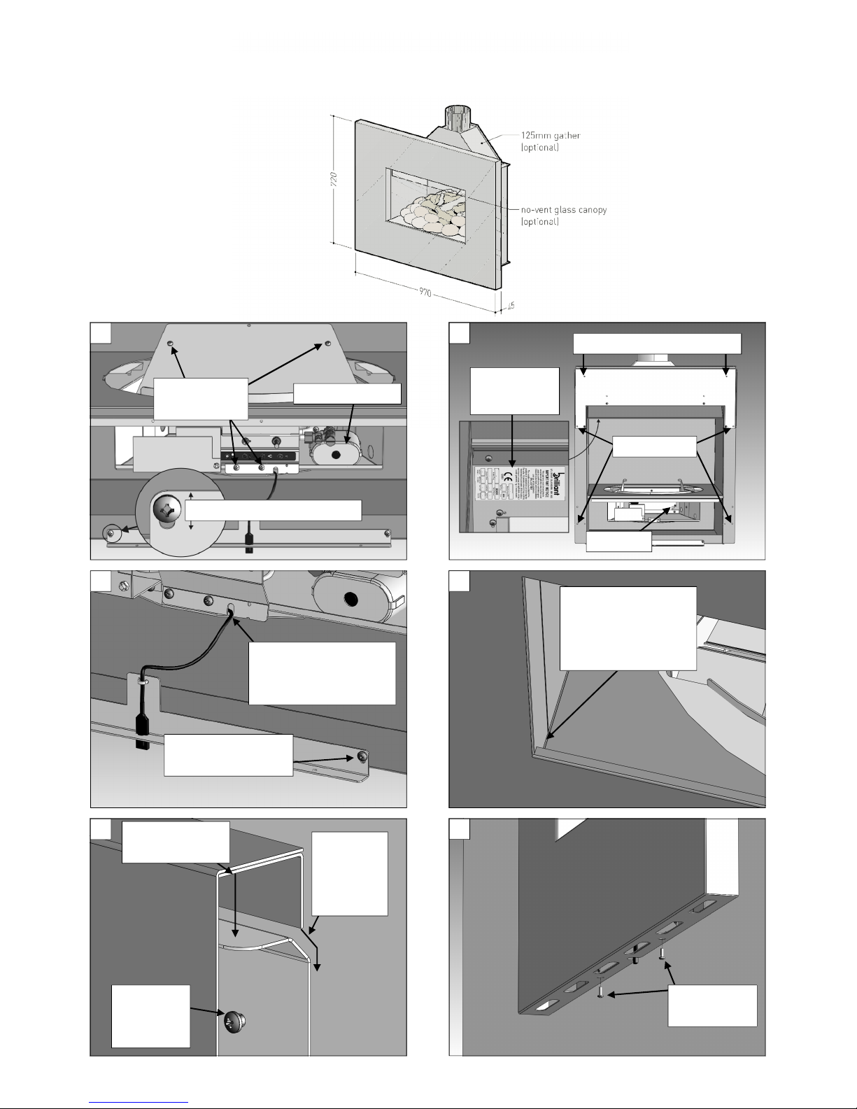
Remove the four screws that secure the burner
to the box, two at the base of the front leg and
two at the top of the rear sloping plate. Remove
the 2 screws that secure the IR Sensor Bracket
to the box. Separate the burner from the box
taking care not to damage the Battery and IR
Sensor leads (see diagrams F.1 and F.2).
The raised hearth is held in place on the shelf
by magnets, pull it forward to release and lift
upwards to remove (see diagram F.5). Carefully
remove the raised hearth and place to one side.
Prepare the gas supply noting the entry point in
the rear of the box. Slacken the screws in the
gas inlet closure plate and remove. Offer the
box into the fireplace opening.
Ensuring the fire is level left to right, mark the
positions of the four fixing holes in the outer
frame. Remove the box, drill and plug the fixing
holes (see diagram F.1)
Partially peel the protective plastic coating away
from the metal box anywhere it may become
trapped. Apply a thin bead of silicon sealant
around the rear edge of the frame. Insert the
gas pipe through the pipe entry opening and
insert the box fully into the fireplace opening.
Secure the box to the fireplace opening using
the four fixing holes using the screws provided
(see diagram F.1). Refit the inlet closure plate.
GAS CONNECTION
Note the position of the isolating tap and
disconnect it. Shape and cut the gas supply pipe
and ensuring the gas supply pipe is clean
internally connect to the isolating tap. Refit the
burner ensuring that the battery lead is routed
through the hole at the rear right and the IR
sensor is not trapped at the front (see diagram
F.2). Connect the gas supply. Secure with the
four screws. Connect the battery and place in
the base of the box (see diagrams F.1 and F.3).
Fit the IR Sensor Bracket to the bottom of the
box as (see diagrams F.1 and F.2). Ensure that
the lead is not trapped or positioned near a heat
source (e.g. pilot flame). Refer to Section P for
commissioning instructions.
FITTING THE SURROUND
Remove all the remaining protective plastic
coating from the firebox and surround.
The surround will hang on the bracket at the top
of the box. Have a look at the rear of the
surround to understand what part will sit on this
bracket. The surround is then secured at the
bottom with two brackets left and right. These
bottom brackets must be in the raised position
before fitting the surround (see diagrams F.4a
and F.6a).
Offer the surround to the box making sure it is
central and lift onto the hanging bracket. The
surround will drop down into the hanging
bracket. Check to ensure that it is central with
the box. Secure the bottom against the wall
using the two brackets. Loosen the screw and
insert the bracket into the slot in the surround.
Push the surround and bracket back against the
wall and tighten the screw (see diagrams F.4b
and F.6b).
FITTING THE RAISED HEARTH
Position the raised hearth in the firebox above
the burner. The narrow strip at the rear will fit
down behind the burner so there is no need to
remove the burner. Lower into the position and
push back fully to engage the magnets.
Centralise it in the box.
Ensure the firebox is properly sealed
and fixed to the fireplace opening. If
not properly sealed to the wall, the
surround may overheat resulting in
damage to the surround.
CAUTION
Page 21
21
2
Fixing Holes
Frame Tensioning Holes
Gas Inlet
Data Badge
(Roof of Box)
1
Frame Height Adjustment
Battery Position
Burner Fixing
Points
5
Slide down
behind
Support
Bracket
Frame sits on
support bracket
Frame
Tensioning
Screw
INSTALLATION - STORM 22 G
6
Frame Fixing
Screws
4
Centralise inner
flanges of the frame
on the sides of the
raised hearth
3
Ensure correct
positioning of IR
sensor cable in slot
IR sensor bracket
fixing screws (2)
Page 22

22
Remove the four screws that secure the burner
to the box, two at the base of the front leg and
two at the top of the rear sloping plate. Remove
the 2 screws that secure the IR Sensor Bracket
to the box. Separate the burner from the box
taking care not to damage the Battery and IR
Sensor leads (see diagrams G.1 and G.3).
Remove the Raised Hearth and place to one
side. Remove any packaging from the box.
Prepare the gas supply noting the entry point in
the rear of the box. Slacken the screws in the
gas inlet closure plate and remove. Offer the
box into the fireplace opening.
Ensuring the fire is level left to right, mark the
positions of the four fixing holes in the outer
frame. Remove the box, drill and plug the fixing
holes (see diagram G.2)
Partially peel the protective plastic coating away
from the metal box anywhere it may become
trapped.
Apply a thin bead of silicon sealant around the
rear edge of the frame. Insert the gas pipe
through the pipe entry opening and insert the
box fully into the fireplace opening.
Secure the box to the fireplace opening using
the four screws provided.
Refit the gas inlet closure plate.
Remove the plastic protective film from the
raised hearth and place it onto the raised hearth
metal shelf. It does not require fixing down.
GAS CONNECTION
Note the position of the isolating tap and
disconnect it. Shape and cut the gas supply pipe
and ensuring the gas supply pipe is clean
internally connect to the isolating tap. Refit the
burner and connect the gas supply. Secure with
the four screws and connect the battery and
position it on the shelf under the gas isolating
tap. (see diagrams G.1 and A.2).
Fit the IR Sensor Bracket to the bottom of the
box as shown in diagrams G.1 and G.3. Ensure
that the lead is not trapped or positioned near a
heat source (e.g. pilot flame). Refer to Section P
for commissioning instructions.
FITTING THE FRAME
Remove all the remaining protective plastic
coating from the firebox. Offer the frame to the
appliance. Align the inner flanges of the frame
with the sides of the raised hearth, see diagram
G.4.
Hook the top flange over the frame support
bracket and slide down behind. It will sit on the
top face of the support bracket, see diagram
G.5. The bottom of the frame may need to be
pulled away from the wall to clear the bottom
fixing bracket, see diagram G.6.
The frame support bracket has two frame
tensioning holes (see diagrams G.2 & G.5) in the
top corners to enable the fit of the surround to
be adjusted to suit the wall. If when the
surround is fitted it does not fit securely against
the wall then remove the frame and bracket
from the fire, drill the wall, and use two screws
and wall plugs to pull the support bracket back
towards the wall at the top to improve the fit.
When the surround fits well, remove all the
protective plastic coating and secure in place
with the two screws provided (see diagram G.5).
Page 23
23
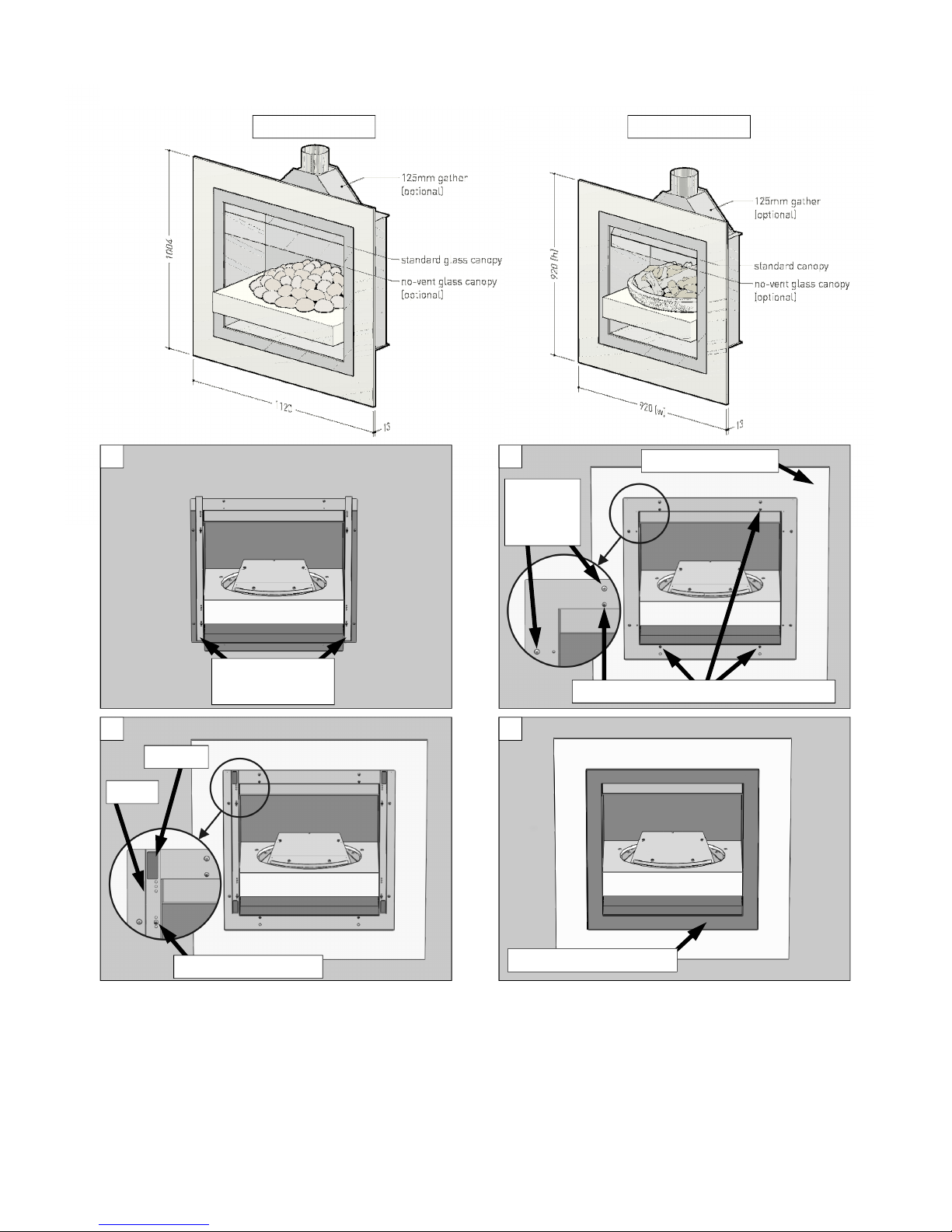
This range of fires use either the FRAME 30 or
FRAME 22 box. For installation of the box please
refer to Section D.
Remove the Frame Locator Strips (4 screws). Fit
the Corian
®
surround to the box using four
screws. The surround bracket has clearance
holes that fit over the box fixing screws. (refer to
diagrams H.1 and H.2).
Replace the frame locating strips over the
surround bracket. Place the 4 magnets on these
strips. Fit the frame in place onto the magnets
(refer to diagrams H.3 and H.4).
INSTALLATION - GEOMETRY 30, GEOMETRY 22 H
GEOMETRY 30 GEOMETRY 22
1
Remove Frame
Locator strips
4
Stainless Steel Frame
2
Corian® Surround
Box Fixing
Screws
Clearance
Corian® Surround Fixing Screws (4)
3
Use CENTRE
CENTRE CENTRE
CENTRE Holes
Magnet
Flange
Page 24
24
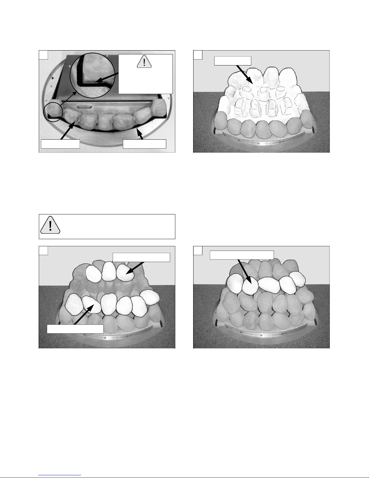
PLACEMENT OF CERAMICS - PEBBLE J
2
Underbed
2. Holding the underbed by the top rear,
position it against the front ceramic piece.
Ensure that it does not overlap the burner
slot.
3
First Row 6 Pieces
Third Row 3 Pieces
3. Place first and third rows of loose pebbles
as shown. They should not overlap each
other and should be as spaced out as
possible.
4
Second Row 5 Pieces
4. Place second row of loose pebbles as
shown. They should not overlap each other
and should be as spaced out as possible.
Alter the angle of the loose pebbles to
produce a good flame picture.
Failure to place this piece correctly will
result in damage to your appliance.
CAUTION
1
Front Piece
MUST SIT BEHIND
THESE TABS ON
THE BURNER
Curved Flange
1. Locate the base of the front ceramic piece
up against the brackets at the front edge,
either end of the burner. It must sit flat on
the burner without a gap underneath.
Ensure that it is NOT
NOT NOT
NOT sat on top of the
curved flange or the tabs shown above.
Page 25
25
1
3
3 2
4
5
4
5
7
6
6
9
8
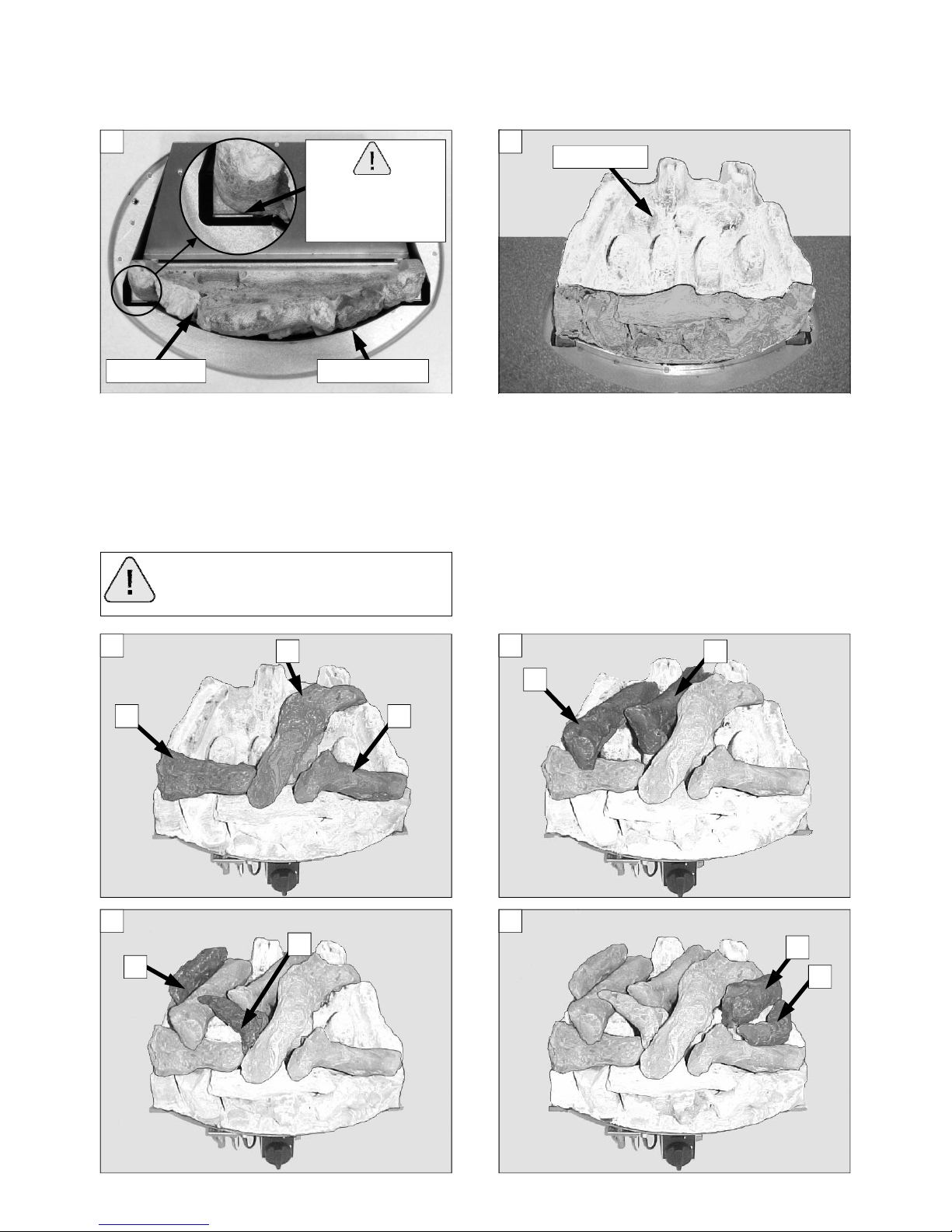
PLACEMENT OF CERAMICS - DRIFTWOOD AND CHARCOAL K
Failure to place this piece correctly will
result in damage to your appliance.
CAUTION
2
Underbed
2. Holding the underbed by the top rear,
position it against the front ceramic piece.
Ensure that it does not overlap the burner
slot.
3. Following diagrams K.3 to K.6 carefully
place the numbered loose driftwood
pieces.
1
Front Piece
MUST SIT BEHIND
THESE TABS ON
THE BURNER
Curved Flange
1. Locate the base of the front ceramic piece
up against the brackets at the front edge,
either end of the burner. It must sit flat on
the burner without a gap underneath.
Ensure that it is NOT
NOT NOT
NOT sat on top of the
curved flange or the tabs shown above.
Page 26
26
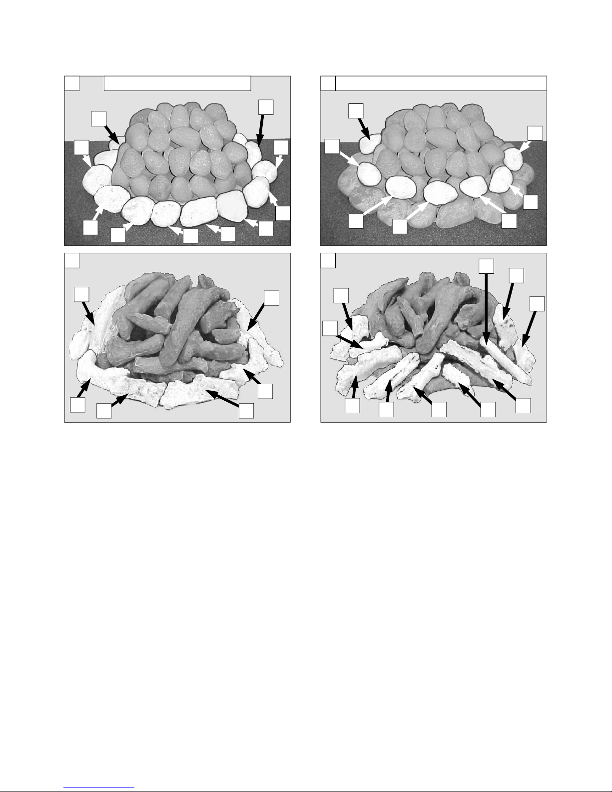
Place the numbered outer ceramic clusters into
the gap around the burner starting with number
1 at the left rear.
Place number 2 next to number 1 and so on
until number 10 for pebble versions and number
6 for driftwood and charcoal versions at the
right rear (see diagrams L.1 or L.3)
Place the loose outer ceramic pieces, marked
with “X” on the underside, around the burner
ceramics on top of the outer clusters (see
diagrams L.2 or L.4).
Ensure the outer ceramics are evenly spaced
Ensure the outer ceramics are evenly spaced Ensure the outer ceramics are evenly spaced
Ensure the outer ceramics are evenly spaced
and do not overlap or interfere with burner
and do not overlap or interfere with burner and do not overlap or interfere with burner
and do not overlap or interfere with burner
ceramics.
ceramics.ceramics.
ceramics.
Do not add any of the outer ceramic pieces to
Do not add any of the outer ceramic pieces to Do not add any of the outer ceramic pieces to
Do not add any of the outer ceramic pieces to
the burner ceramics.
the burner ceramics. the burner ceramics.
the burner ceramics.
Do not use more pieces than originally supplied.
Do not use more pieces than originally supplied. Do not use more pieces than originally supplied.
Do not use more pieces than originally supplied.
A
B
C
D E F
G
H
J
K
4 3
2
1
3 4
5
6
2 Loose Outer pieces marked “X” on underside
X
X
X X
X
X
X
1 10 Numbered Outer Clusters
2
3
4
10
1
5
6
7
8
9
PLACEMENT OF CERAMICS - OUTER CERAMICS L
Page 27
27
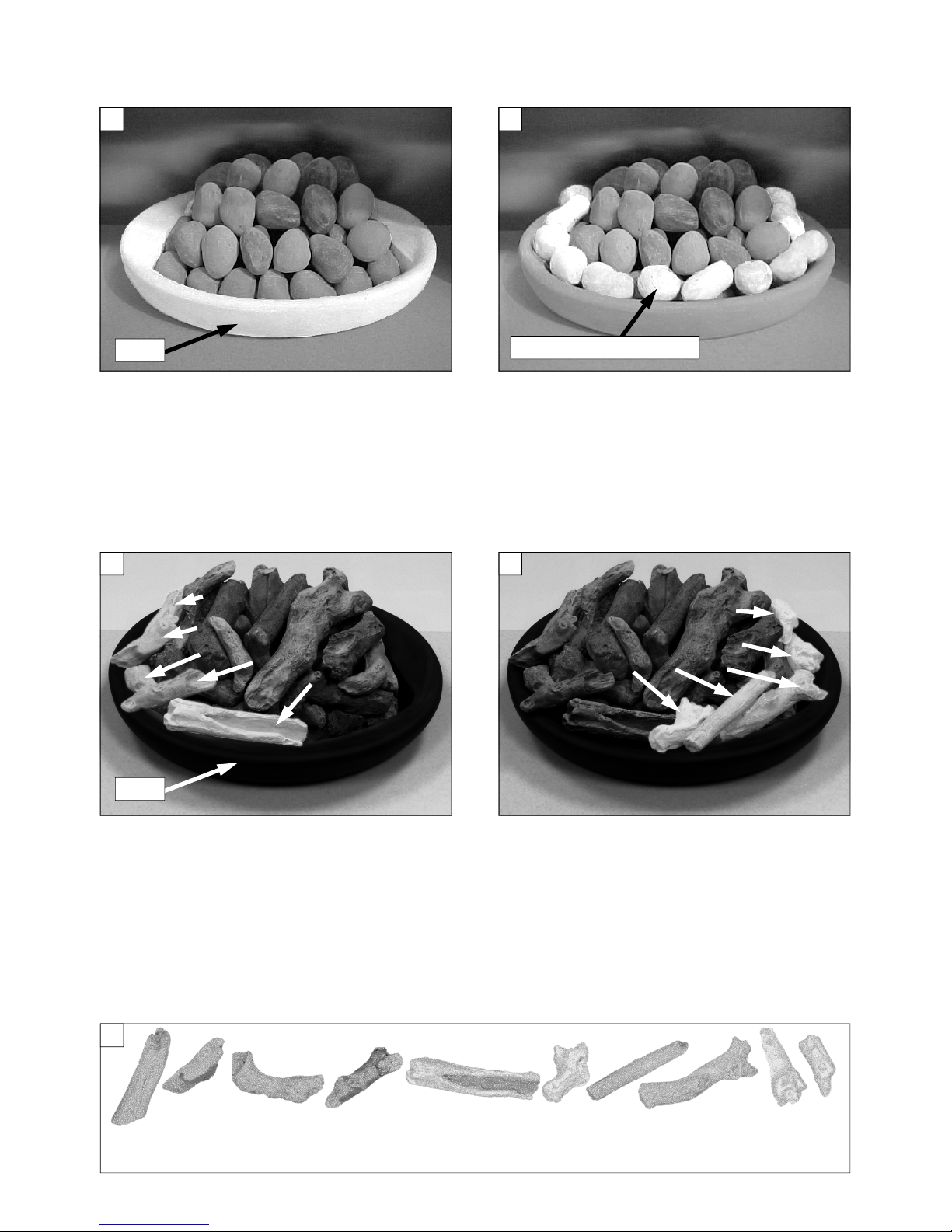
PLACEMENT OF CERAMICS - DISH PEBBLE M
2
Outer Pebbles 12 Pieces
1
Dish
1. The Dish is designed to fit over the existing
ceramics. Position the Dish over the
ceramics and slowly lower into position.
It will sit inside the cut-out in the raised
hearth.
2. Place the 12 small pebbles evenly around
the edge of the dish to complete the effect.
2
6 7
8
9
10
1
5
4
3
2
1
Dish
PLACEMENT OF CERAMICS - DISH DRIFTWOOD N
Please note that the numbers given here are NOT
NOT NOT
NOT marked on the ceramic pieces.
1 2 3 4 5 6 7 8 9 10
3
1a. The Dish is designed to fit over the existing
ceramics. Position the Dish over the
ceramics and slowly lower into position.
It will sit inside the cut-out in the raised
hearth.
1b. Place the first 5 pieces of outer driftwood
as shown above referring to diagram N.3.
2. Place the remaining 5 pieces of outer
driftwood as shown above referring to
diagram N.3.
Page 28

28
COMISSIONING
Remove all plastic protective films.
The LEDGE and STORM products require
commissioning to be carried out prior to fitting
the surround / frame.
Ensure the Isolating tap is fully open and check
for gas leaks.
Connect a pressure gauge to the inlet pressure
test point, and referring to the user instructions
light the fire.
Check the inlet pressure is 20mbar for NG or
37mbar for LPG when on the high setting.
Wait ten minutes for the fire to establish then
with all windows and doors in the room closed,
check for clearance of combustion products.
Insert the end of a smoke match 25mm below
and 25mm back from the bottom edge of the
canopy, test along the opening and check the
smoke is drawn in. If spillage is detected open a
window and repeat the test to assess if an air
vent is required. If spillage persists, seek expert
advice.
The fault must be rectified before the fire is
used.
If there is an extractor fan fitted in a nearby
room, repeat the test with the fan turned on and
any interconnecting doors left open.
Hand over the instructions and explain to the
user the operation and lighting procedure of the
fire. Impress upon the user that servicing of the
fire should be carried out at least every twelve
months, and only by a qualified person.
SERVICING
Carefully remove the outer ceramics and place to
one side.
Carefully remove the burner ceramics and place
to one side, do not mix with outer ceramics.
LEDGE versions only– Refer to Section F and
remove the raised hearth and surround to gain
access to the gas supply.
STORM version only– Refer to Section G and
remove the frame to gain access to the gas
supply.
Locate the isolating tap and turn the gas off.
Undo the inlet nut and disconnect the gas pipe.
Remove the four screws that secure the burner
to the box, two at the base of the front leg and
two at the top of the rear sloping plate.
Inspect the full installation.
Clean all lint and dirt off the burner, paying
particular attention to the injector, venturi and
flame ports.
Referring to the installation instructions
re-assemble the burner to the box and refit all
ceramics.
Carry out a spillage test.
COMISSIONING AND SERVICING P
Page 29

29
[Blank]
Page 30

30
[Blank]
Page 31

31
[Blank]
Page 32

32
LFL Group Limited . Thwaites Close . Blackburn BB1 2QQ . England
Tel 01254 682384 . Fax 01254 672647 . www.brilliantfires.co.uk . info@brilliantfires.co.uk
20 04 2011
Brilliant Fires Limited
Thwaites Close
Blackburn BB1 2QQ
England
tel +44 (0)1254 682384
fax +44 (0)1254 672647
www.brilliantfires.co.uk
[email protected]
 Loading...