

Page 1
4
Brilliant 401B
USER, INSTALLATION AND SERVICING
INSTRUCTIONS
Please read these instructions before installation and use
Keep this booklet handy for future reference
Page 2

2
CONTENTS
3
9
13
15
17
21
23
25
USER’S INSTRUCTIONS
INSTALLER’S INSTRUCTIONS
INSTALLATION
FLUE SYSTEM INSTALLATION
SETTING THE APPLIANCE
WIRELESS REMOTE CONTROL
COMMISSIONING AND SERVICING
FAULT FINDING
Page 3
3
USER’S INSTRUCTIONS A
This user manual will give you the information
you need to operate the appliance properly and
safely.
Carefully read this user manual prior to using
the appliance.
Keep this user, installation and servicing
manual in a safe place.
As a user you are only entitled to perform
the work described in the user manual.
Any other work requires a Gas Safe
registered installer.
Www.GasSafeRegister.co.uk
In case of questions or doubts, please contact
your installer.
INTRODUCTION
Your appliance is a room-sealed atmospheric
gas-fired heating appliance. A room-sealed
appliance does not extract the combustion air
from the living environment, but from outside.
The appliance is operated by means of a
wireless remote control that works on batteries.
For some appliances, no control hatch is
supplied. In that case, the receiver and gas
control are placed under the appliance.
SAFETY
Carefully read and observe the safety
precautions and instructions in this manual.
DO NOT make any changes to the appliance.
Servicing should be carried out at least
annually, but depending upon site conditions
more frequently.
A cracked or broken glass panel must be
replaced. DO NOT use the appliance until it has
been replaced.
Ensure that combustible objects or materials
such as curtains have a distance from the
appliance and the flue of at least 50 cm.
DO NOT dry clothes, towels etc. on or near the
appliance as this is a fire risk.
Avoid contact with hot parts of the appliance to
prevent burns.
DO NOT leave children, the elderly or infirm
alone with a burning appliance.
Keep the remote control out of reach from
children the elderly or infirm.
OPERATING YOUR APPLIANCE
(FIRST TIME OPERATION)
We recommend that you allow the chimney
breast installation to completely dry for at least
6 weeks before using your appliance for the first
time to prevent cracks in the plaster or stone
work.
In order to be able to use the wireless remote
control, you must set a communication code
between the remote control and the receiver,
prior to operating your appliance. This should
have been done by your installer but if not or you
have bought a replacement handset or receiver
then please follow the instructions in the
section SETTING THE COMMUNICATION CODE
During the initial use period the flame picture is
affected by the evaporation of volatile
components.
DISCOLORATION OF WALLS AND CEILINGS
As with all high efficiency room heaters,
discolouration of the walls and ceilings can
occur if the room the appliance is installed in
contains contaminants such as; Smoke, burning
candles, oil lamps, etc.
The convection of the hot air from the appliance
can deposit these contaminants on colder walls.
These problems can be (partly) solved by
ventilating the room where the appliance is
installed.
WIRELESS REMOTE CONTROL
The appliance is supplied with a remote control.
When the appliance is lit for the first
time, an unpleasant smell may occur
as volatile components evaporate
from paint, materials, etc. This is
normal in the first few hours of
operation. Place the appliance on the
highest setting, ventilate the room
well and remove pets from the room.
CAUTION
Close the gas isolation valve if the
appliance ignites with a pop sound and
contact the installer.
CAUTION
Page 4
4
Ignition, controlling the flame height and
switching off are performed by the remote
control that operates a receiver in the control
hatch. For some appliances, no control hatch is
supplied. In that case, the receiver is placed
under the appliance.
The receiver and remote control are battery
powered. The receiver requires 4 × AA type
batteries, the remote control requires a 9V PP3
battery. In normal use, the batteries will have an
average life of one year.
You can also use an optional power supply in
place of the batteries in the receiver. Ask your
installer for information. If you wish to use the
optional power supply you will need a 230V
connection near your appliance.
RECEIVER
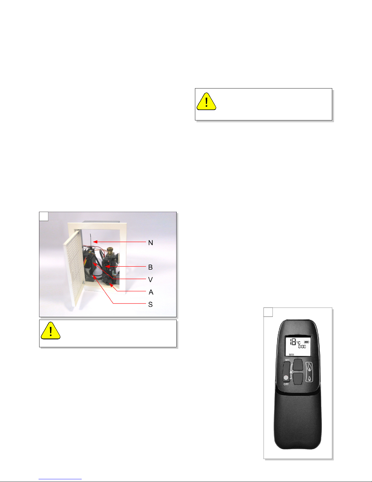
The receiver is located in the control hatch (See
Fig. A1) or is placed under the appliance.
TO REPLACE THE RECEIVER BATTERIES
If the receiver’s batteries are low, you will hear
3 short beep sounds when attempting to light
the burner.
The receiver is situated in the optional Control
Hatch on the side of the chimney breast (See
Fig. A1). If your appliance does not have a
control hatch the receiver will be under the fire.
The receiver is fitted with 4 AA batteries.
Pick up the receiver and slide the cover off.
Remove the old batteries and replace all 4
batteries at the same time using new alkaline
AA or equivalent batteries, DO NOT mix old and
new batteries.
When fitting the new batteries, ensure correct
polarity by referring to the polarity diagrams
inside the battery compartment. Replace the
cover and place the receiver back in the location
it came from.
Do not place the antenna (N) too close to the
ignition cable and/or metal parts. Ensure the
antenna is pointing upwards (for the correct
position, see Fig. A1).
Ensure the ignition cable is not running over/
alongside metal parts: this will weaken the
spark.
Do not lay the ignition cable over the receiver:
this could damage the receiver
TO REPLACE THE HANDSET BATTERY
If the handset battery requires replacing turn
the handset over and remove the battery cover.
Pull out the battery and carefully disconnect it
from the lead. The replacement battery must be
a new alkaline PP3 or equivalent battery.
REMOTE CONTROL OPERATION
The appliance’s standard functions such as
ignition, controlling the flame height, standby
(pilot burner) position and switching off are
performed in the MAN
position, the manual
control of the remote
control (see Fig. A2).
In addition, the remote
control can also be
used to set a number of
additional functions:
Temperature display in
degrees Celsius or
Fahrenheit, time,
thermostat function and
timer for thermostat
function.
CAUTION
Before reporting a fault on your fire
ensure the batteries are in good
condition.
CAUTION
Batteries are regarded as “small
chemical waste” and must not be
disposed of in the household rubbish.
A2
A1
Page 5
5
Although highly improbable, we cannot rule out
Although highly improbable, we cannot rule out Although highly improbable, we cannot rule out
Although highly improbable, we cannot rule out
that your appliance’s ignition process can be
that your appliance’s ignition process can be that your appliance’s ignition process can be
that your appliance’s ignition process can be
started unintentionally through other remote
started unintentionally through other remote started unintentionally through other remote
started unintentionally through other remote
controls.
controls. controls.
controls. Unintended ignition of your appliance
is solved by setting a new communication code
between remote control and receiver (see
below)
If leaving your appliance unattended for a long
period, set knob A on the gas control to the
position MAN (see Ignition below)
If the appliance will not be used for a longer
period, close the gas isolation valve next to your
appliance.
Observe stated precautions / safety instructions,
even when the appliance is not in use.
SETTING THE COMMUNICATION CODE
Prior to using your appliance a communication
code must be set between the Remote Receiver
and the Remote Handset. The code is chosen
randomly from the 65000 available codes. As a
result, the chance that other remote controls
near you are using the same code and affect the
operation of your appliance is very small.
The code should already have been set by your
installer but if it hasn’t or your have bought a
replacement handset or receiver then the code
will need to be set again. Follow this procedure
to set the code:
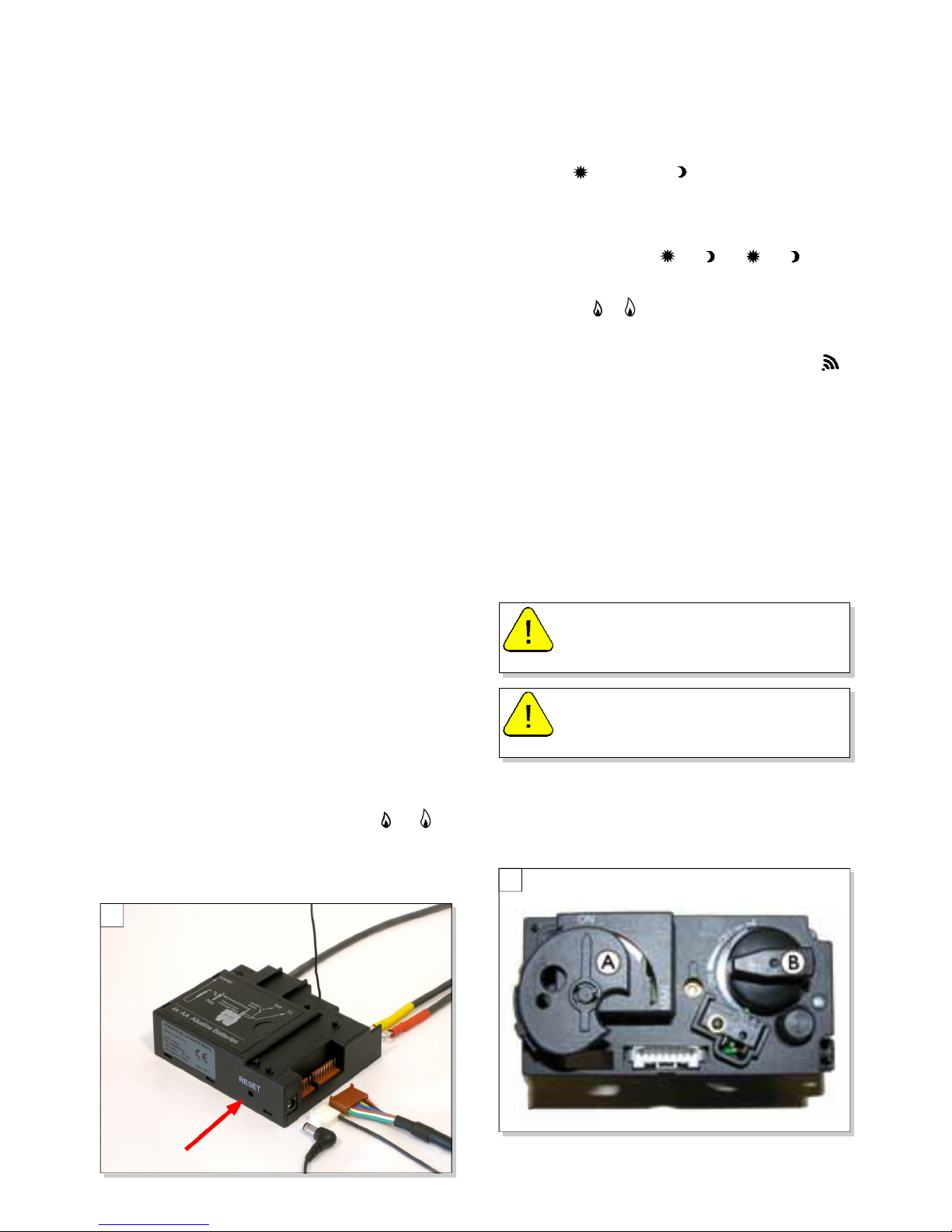
Hold down the reset button on the receiver, until
you hear two consecutive sound signals (see
Fig. A3).
After the second, longer signal, let go of the
reset button. Then press and hold the or
button on the remote control within 20 seconds,
until you hear an extra long sound signal. This is
confirmation that the code has been set.
MAN POSITION
By briefly pressing the SET button on the
handset, you will go through the following
functions:
MAN → TEMP → TEMP → (P*)
TIMER → MAN
where, depending on the timer setting:
(P*) is displayed as P1 , P1 , P2 , P2 .
You can also go back to the MAN position by
pressing the or button.
When pressing the buttons (with the exception
of the SET button), the transmission symbol
will appear to indicate that transmission is
taking place between the remote control and
the receiver.
The receiver acknowledges the transmission
with a sound signal.
The appliance will automatically enter the
standby position, if there is no transmission for
6 hours.
Set the remote control to the MAN position.
IGNITION
IGNITE THE APPLIANCE AS FOLLOWS
Set knob A on the gas control to ON (knob B is
controlled automatically) (see Fig. A4).
A3
Always wait 5 minutes after the pilot
flame has gone out, before you
reignite the appliance.
WARNING
During the ignition process, you are
not allowed to operate control knob B
on the gas control manually. Fig A4
WARNING
A4
Page 6
6
The gas control is located in the control hatch
or is placed under the appliance.
Simultaneously press the OFF and (large
flame) buttons on the remote control.
Let go of the buttons when a short sound signal
indicates that the ignition process has been
started.
The ignition process continues as follows:
The continuous signals will indicate that the
ignition process is active.
A short sound signal will indicate that the
ignition process has finished.
The appliance will automatically switch to the
highest position of the main burner, which will
start to burn in a few seconds.
FLAME HEIGHT ADJUSTMENT / STANDBY
The flame height can be adjusted continuously
by using the buttons and . By continuing to
lower the flame height, the appliance can be set
to the standby position. This means that only the
pilot burner will remain alight.
Press and hold the (small flame) button to
lower the flame height and/or to set the
appliance in the standby position.
Press and hold the (large flame) button to
raise the flame height and/or to switch on the
main burner from the standby (pilot burner)
position.
SWITCHING OFF
Switch the appliance off by pressing the OFF
button. The pilot burner will also go out.
TEMPERATURE DISPLAY
The room temperature can be indicated on the
display in degrees Celsius (°C) using a 24 hour
clock or degrees Fahrenheit (°F) using a 12 hour
clock. To change between these options,
simultaneously press OFF and (small flame),
until the desired display appears.
TIME
The display will indicate the current time.
After fitting the battery or simultaneously
pressing (large flame) and (small flame),
the time indication will flash on the display and
you will be able to adjust the time.
Simultaneously press and until the time
indication flashes on the display.
Press the (large flame) button to set the hour.
Press the (small flame) button to set the
minutes.
Press OFF to return to the MAN position, or wait
for the system to automatically return to the
MAN position.
THERMOSTAT FUNCTION
Using the thermostat function you can set a day
temperature and a night temperature and the
system will automatically adjust the appliance
to maintain the room at the set temperature.
The TEMP and TEMP symbols on the display
refer to day and night temperature respectively.
To be able to use the day/night temperature
function, the appliance must be in the standby
position. Always leave the remote control
handset in a position where it can sense the
room temperature. Make sure this position is
free from temperature influences such as
draughts, heat from radiators and direct
sunlight.
CAUTION
If the pilot burner is not burning after
3 ignition attempts, you must close
the gas tap and contact your installer.
CAUTION
When igniting the pilot burner, you will
hear sound signals. After the last
short sound signal, the main burner
should be largely ignited within about
10 seconds. If this is not the case, you
must close the gas tap and contact
your installer.
CAUTION
If the appliance ignites with a pop
sound, you must close the gas tap and
contact your installer.
If you continue to hold down the
(large flame) button on the remote
control, the main burner should be
largely ignited within about 10
seconds. If this is not the case, you
must close the gas tap and contact
your installer.
CAUTION
CAUTION
If the appliance ignites with a pop
sound, you must close the gas tap and
contact your installer.
Page 7

7
Example:
Setting the TEMP function you can keep the
day temperature in the room at 20 °C; while you
use the TEMP function at night to maintain a
room temperature of 15 °C.
SETTING DAY/NIGHT TEMPERATURE
By using the SET button, you will go through the
following functions:
MAN → TEMP → TEMP → (P*)TIMER →
MAN
Briefly press the SET button to enter the
TEMP or the TEMP position.
Press the SET button until the temperature on
the display flashes.
Set the required temperature by using the
buttons (large flame) and (small flame).
The minimum temperature you can set is 5 °C /
40 °F;
Control of the night temperature is switched off
by lowering the temperature until
--
----
--
appears on
the display.
Press the OFF button or wait until position
TEMP or TEMP appears on the display.
ACTIVATING THE THERMOSTAT FUNCTION
For activating the thermostat function, you must
proceed with the following steps:
Place the appliance in the standby (pilot burner)
position using the (small flame) button.
Set the day/night temperature.
Choose the TEMP or TEMP function using
the SET button.
TIMER FOR THERMOSTAT FUNCTION
Using the timer enables you to set two times
per 24 hours for switching on the day
temperature and two times per 24 hours for
switching on the night temperature.
In order to control the night temperature, it
should be set to at least 5 °C / 40 °F.
If the night temperature is set to the
--
----
--
position,
the appliance will remain in the standby
position. The appliance will only switch on at the
next switch-on time of the day temperature.
The appliance must be in standby position in
order to be controlled by the timer.
Example of switch times:
You have set a day temperature and night
temperature of, for example, 20 °C and 15 °C.
P1 TIMER = 7 hours; the temperature will go
to 20 °C at 7 am.
P1 TIMER = 9 hours; the temperature will go
to 15 °C at 9 am.
P2 TIMER = 17 hours; the temperature will go
to 20 °C at 5 pm.
P2 TIMER = 22 hours; the temperature
returns to 15 °C at 10 pm.
SETTING TIMES FOR THE TIMER
To set the timer, proceed as follows:
Set the day and night temperature as described
above.
Briefly press the SET button to enter the (P*)
TIMER position.
Press the SET button until P1 TIMER is
displayed and the time flashes.
Set the first switch on time of the day
temperature using the buttons (large flame)
and (small flame).
Briefly press the SET button to set the next time
of the cycle, P1 TIMER.
Continue to set the times P2 TIMER and P2
TIMER.
Press the OFF button or wait until position (P*)
TIMER appears on the display.
ACTIVATING THE TIMER MODE
Follow the steps below for activating the timer
control:
Place the appliance in the standby (pilot burner)
position using the (small flame) button.
Set the day/night temperature if you have not
yet done so; for this, see above
Set the timer times P1 TIMER, P1 TIMER, P2
TIMER and P2 TIMER.
Choose the (P*) TIMER function using the SET
button.
Page 8

8
SERVICING
Replacement parts are available from your
supplier or through our mail order service.
Always quote the product code and serial
number when ordering new parts. This
information is on the burner data badge.
Servicing should be carried out at least
annually, but depending upon site conditions
more frequently.
As user, you are only allowed to clean the
appliance on the outside:
Do not use corrosive detergents.
Paint damaged, resulting from objects
falling/placed against the appliance are not
covered by the warranty.
ENVIRONMENT
Packaging materials must be disposed off in
accordance with local regulations.
Batteries are considered as small chemical
waste and must not be disposed of in the
household waste.
When the appliance has reached the end of its
life, you should have it processed sensibly, so
that the appliance or parts of it can be recycled.
GUARANTEE
Your Brilliant appliance is guaranteed for 12
months from the date of purchase against faulty
materials or workmanship. Please report any
fault to your dealer.
If your appliance is found to be defective within
the guarantee period we will repair or replace
the faulty component. Should a component or
the appliance need to be returned to our works
it must be sent carriage paid. Labour charges
are not included.
The guarantee is subject to the provisions that
the appliance has been correctly installed and
used in accordance with the manufacturers
instructions and has not been misused,
modified or inexpertly repaired.
This guarantee does not cover reimbursement
of any third party repair or replacement costs
that we haven’t agreed to in writing, nor does it
cover compensation or consequential losses,
stress and inconvenience arising from delays
caused by factors outside our reasonable
control. Your statutory rights are not affected.
Page 9
9
INTRODUCTION
This fire is CE approved to the European
Standard EN 613 and meets the essential
requirements of the Gas Appliance Directive.
The fire must be installed and serviced by a
qualified Gas Safe
Gas SafeGas Safe
Gas Safe registered installation
engineer in accordance with National
and Local Regulations.
www.GasSafeRegister.co.uk
Servicing should be carried out at least
annually, but depending upon site conditions
more frequently.
RELEVANT STANDARDS
Building Regulations Part J
BS 5440 : Part 1 : Flues
BS 5440 : Part 2 : Air Supply
BS 5871 : Part 1 : Installation of gas appliances
BS 6891 : Gas Installation
Before installation ensure that the local
distribution conditions (identification of the type
of gas and pressure) and the adjustment of the
appliance are compatible.
The Gas Category of this fire is I2H and is set for
Natural Gas (G20). Check the Gas Type on the
burner data badge is correctly marked for your
gas supply.
TECHNICAL INFORMATION
NATURAL GAS (G20)
Appliance Classification: C11/C31
Heat Input Max (gross): 8.4 kW
Heat Input Min (gross): 7.6 kW
Heat Output: 6.0 kW
Consumption on High: 0.790 m3/h
Inlet Pressure: 20.0 mbar
Burner Pressure: 15.3 mbar
Burner Injector Size: 2 × Ø1.60mm
Consumption on Low: 0.352 m3/h
Low Setting Injector: Ø1.50mm
Pilot Injector Code: 51
Efficiency: Class 2
Gas Connection Size: 15mm
Weight: 62kg
BATTERY REQUIREMENTS
Control Box: 4 × AA
Remote Handset: 1 × 9V PP3
SITE REQUIREMENTS
Always place the appliance in front of a wall
constructed from non-combustible materials or
properly shielded using 12mm Supalux® or
equivalent heat-resistant material.
Always place the appliance with a minimum
distance of 500 mm from combustible objects or
materials.
Do not cover the appliance or wrap it in an
insulation blanket or any other material.
Make sure that the appliance is stable when
fixed in position.
The fire must be installed in a purpose built
chimney breast using non-combustible and
12mm Supalux® or equivalent heat resisting
materials for the construction, including the top
of the chimney breast, the material inside the
chimney breast and the back wall against which
the appliance will be placed.
A minimum chimney breast ventilation area of
200cm2 is required. The ventilation holes must
be placed as high as possible but the top of the
holes should be at least 30cm from the ceiling
of the room.
The control hatch (optional extra) should be
placed as low as possible. The bottom of the
hatch should not be fitted higher than the top
surface of the appliance burner.
FLUE
The flue system is a concentric pipe system
which can terminate either with a roof terminal
or a wall terminal. The flue system should be
constructed from the spigot of the appliance. If
however the flue needs to be fitted prior to the
appliance for constructional reasons then a
telescopic flue section will be required to
connect the appliance at the time of fitting.
The flue system must comply with the allowable
configurations outlined in Tables 2 and 3
INSTALLATION INSTRUCTIONS B
Page 10
10
GAS SUPPLY
The gas connection to the fire must be in 15mm
copper pipe in accordance with National
Regulations. Any additional pipework must be of
a diameter to ensure adequate pressure at the
fire. Note: The end of the pipe must be covered
to ensure that debris cannot enter the pipe
when being passed through masonry.
An isolation valve (not supplied) must be fitted
adjacent to the appliance, which when closed,
allows the fire to be disconnected for
maintenance or repair in accordance with
National Regulations.
Only use the concentric flue pipe
system supplied by Brilliant. This
system has been tested in conjunction
with the appliance. Brilliant cannot
guarantee proper and safe operation
of other systems and does not accept
any responsibility or liability for the
use of other systems.
WARNING
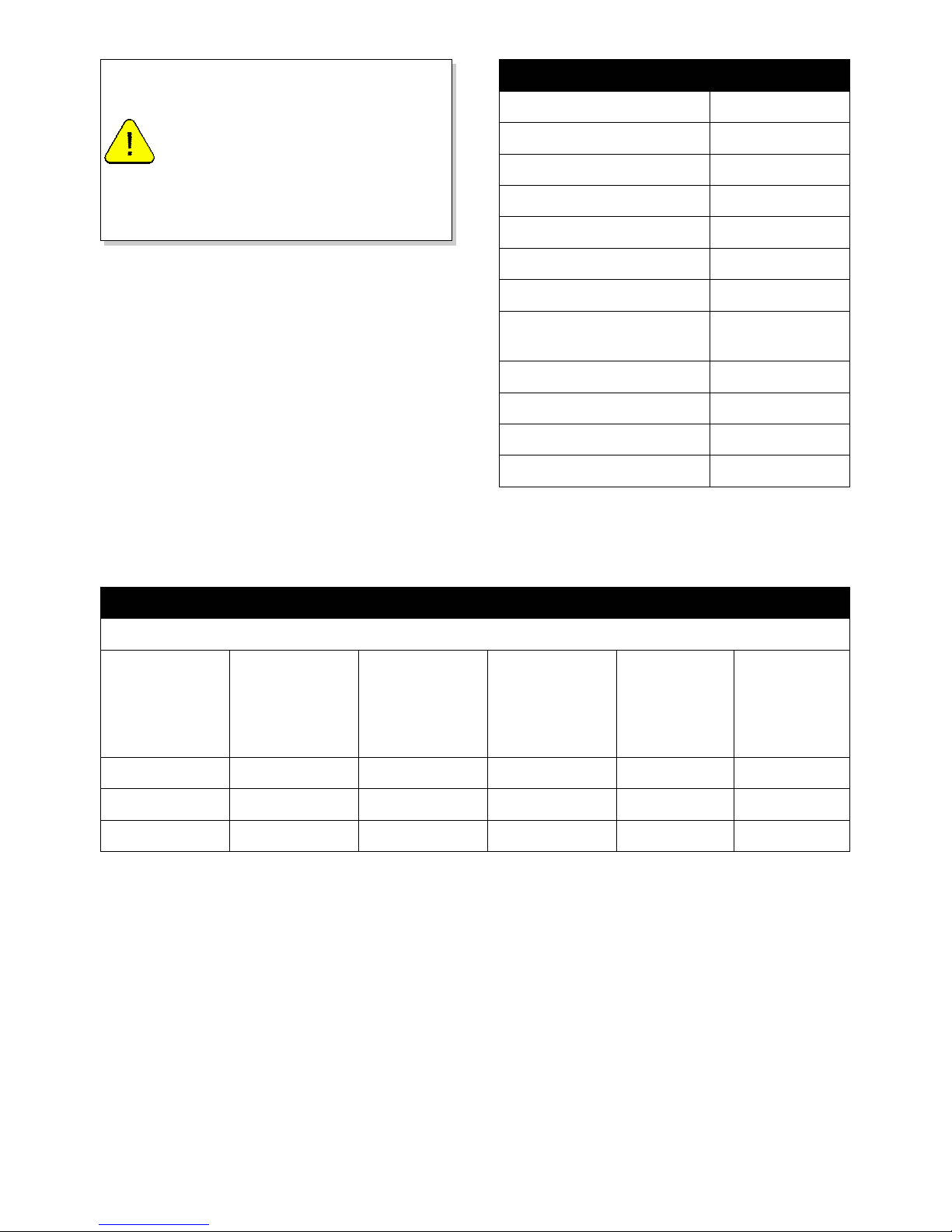
Table 1: Parts included with the delivery
Table 1: Parts included with the deliveryTable 1: Parts included with the delivery
Table 1: Parts included with the delivery
Part
PartPart
Part Quantity
QuantityQuantity
Quantity
Wood Set 1×
Control Hatch Optional
Control Hatch Manual Optional
User and Installation Manual 1×
Gas Inlet adaptor (3/8” - 15mm) 1×
Restrictor Slide 1×
Spare self-tapping screws for
mounting the glass windows
6×
Socket spanner 8mm 1×
Remote control with receiver 1×
9V block battery 1×
AA battery 4×
Table 2: Conditions for setting the appliance
Table 2: Conditions for setting the applianceTable 2: Conditions for setting the appliance
Table 2: Conditions for setting the appliance
Total number of
meters vertical
pipe length
Total number of
metres horizontal
pipe length
(excluding wall
terminal
See figure Air Inlet guide Restrictor slide
Distance of
restriction in
mm
0 0
1)
4 NO NO OPEN
1-4 0
2)
4 YES NO OPEN
1-4 1-3 4 NO NO OPEN
G20
Page 11
11
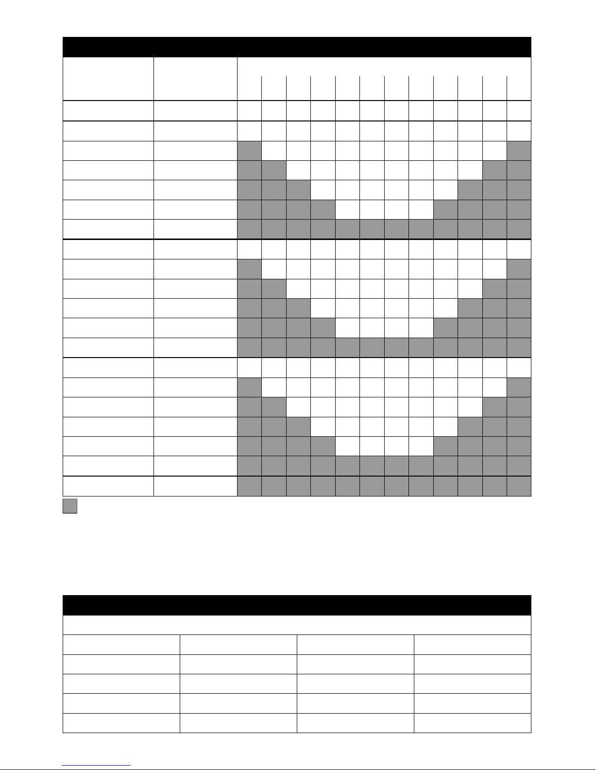
Table 3: Determining permissibility of concentric flue system
Table 3: Determining permissibility of concentric flue systemTable 3: Determining permissibility of concentric flue system
Table 3: Determining permissibility of concentric flue system
G20
Total No. of meters vertical and/or sloping pipe length
11) 2 3 4 5 6 7 8 9 10 11 12
No bends 0 B B B C C C C C D D D D
2 bends 0 A A B B C C C C C C D D
1 A B B B B C C C C C
2 A A B B B C C C
3 A A B B B C
4 A A B B
5
3 bends 0 A A A B B B C C C C C D
1 A A A B B B C C C C
2 A A A B B B C C
3 A A A B B B
4 A A A B
5
4 bends 0 A A A A B B B C C D C C
1 A A A A B B B C C C
2 A A A A B B B C
3 A A A A B B
4 A A A A
5
5 bends -
Total No. of
meters horizontal
pipe length
= Situation not permissible
1)
In this configuration, an unpainted stainless steel wall terminal must be applied.
Table 4: Conditions for the adjustment of the appliance with a roof terminal
Table 4: Conditions for the adjustment of the appliance with a roof terminalTable 4: Conditions for the adjustment of the appliance with a roof terminal
Table 4: Conditions for the adjustment of the appliance with a roof terminal
G20
Situation Air inlet guide Restrictor slide Distance restrictor in mm
A NO NO OPEN
C YES YES 29
D YES YES 25
B YES YES 38
Page 12
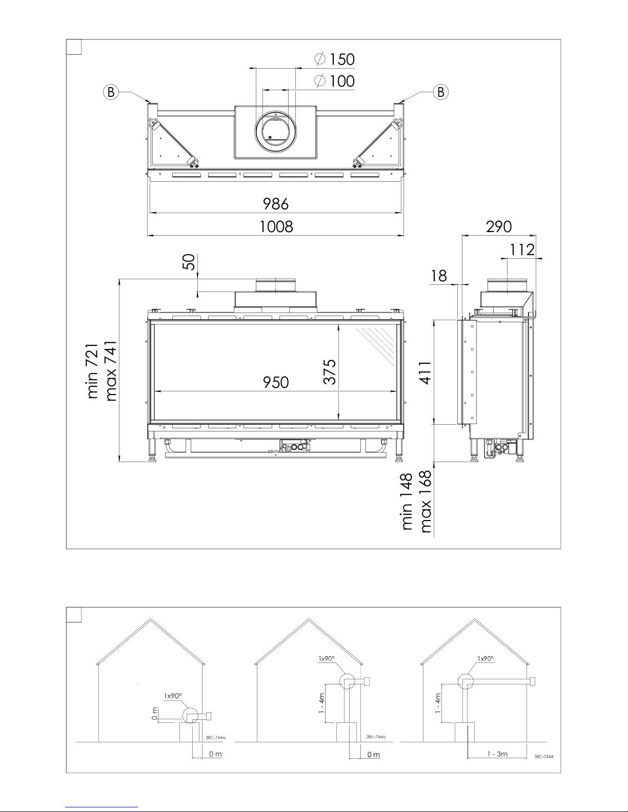
12
B1
B2
Page 13
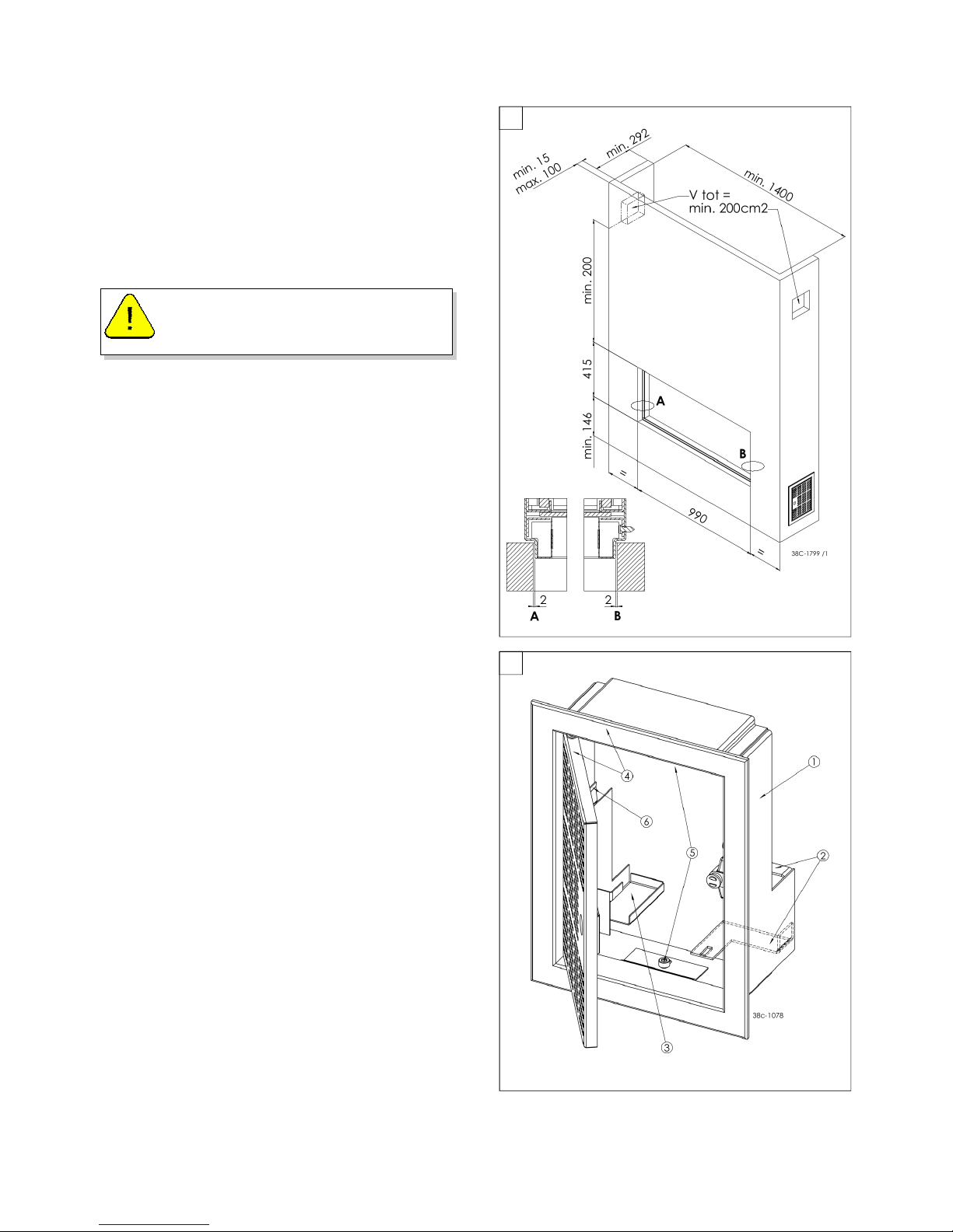
13
The gas control is mounted underneath the
appliance. It must be taken out for fitting in the
control hatch at a later time.
Follow this procedure:
Disconnect the pipes from the gas control
(flexible gas pipe, aluminium pilot burner pipe
and thermocouple 1);
Disconnect the gas control from the burner
mounting plate by unscrewing the self-tapping
screw.
Carefully unwind the red and black wire of
thermocouple 2.
Carefully lay the gas control together with the
wires of thermocouple 2, the ignition cable, the
flexible gas hose, the aluminium pilot burner
pipe and the data plate plus chain in the
direction of the control hatch.
Make sure there is no dirt in gas pipes and
connections, avoid kinks in the pipes.
Make sure the ignition cable doesn’t come into
contact with other wires.
The data plate must remain attached to the
chain.
Set the height and level the appliance using the
adjustable feet.
Do not ignite the appliance before the flue
connections have been fully installed.
CHIMNEY BREAST
In order for efficient operation there must be
sufficient space around the appliance. The
chimney breast must have a minimum
ventilation area of 200cm2. The ventilation holes
must be positioned as high as possible with the
top a minimum of 30cm from the ceiling.
Ideally you should have ventilation holes on both
sides of the chimney breast. Ventilation grills
are available as optional extras.
Ensure that the appliance is not carrying the
weight of the chimney breast.
INSTALLATION
- (WITH OPTIONAL CONTROL HATCH)
C
WARNING
The red wire of thermocouple 2 must
remain connected to the gas control.
C1
C2
Page 14
14
Prior to completely closing the chimney breast,
complete the flue system as described in
Section D and ensure all clamps and fixing
brackets are securely fixed.
Connect the appliance to the wall using wall
brackets (B) (see Fig. 1).
The control hatch (optional extra) should be
placed as low as possible. The bottom of the
hatch should not be fitted higher than the top
surface of the appliance burner.
A number of components are placed in the
control hatch, such as data plate, gas control
and receiver.
To fit the control hatch, make an opening in the
chimney breast of 285mm high x 194mm wide.
Refer to figures C1 and C.2
Unscrew bolts (5) to remove the inner frame (1).
Fit the inner frame into the opening in the
chimney breast.
If the chimney breast is built from bricks, the
inner frame can be built in at the same time.
When using other materials, you can glue the
inner frame or fix it with four flush screws.
Mount the gas control to the brackets of the
inner frame (2) and reconnect the pipes to the
gas control avoid kinking the pipes.
When connecting the thermocouple to the gas
control, first screw it in until hand tight then
tighten it a quarter turn using a suitable
spanner.
The pilot burner pipe must be protected against
possible corrosive influences as a result of, for
example, humidity, cement that has fallen down,
dirt that has fallen down from the chimney, etc.
The pilot burner pipe should remain
permanently free from the ground and the walls
of the room in which the appliance is built in.
CONNECT THE GAS SUPPLY
Make sure there is no dirt in the gas inlet pipe
and connections. Connect the gas inlet pipe to
the gas control. Bleed any air from the gas line.
Place the receiver in the holder (3); for
connections, see Section F.
Place the data plate in its intended clamp (6).
Fix the outer frame with door (4) to the inner
frame using 2 socket cap screws (5).
You can place the outer frame in such a way,
that the door turns to the left or to the right.
Do not plaster on or over the edges of
the construction frame, because:
a) The heat of the appliance could
cause the plaster to crack.
b) It will no longer be possible to
remove/replace the glass panel.
WARNING
WARNING
When using a plaster finish, allow the
chimney breast to dry for at least six
weeks prior to using the appliance in
order to prevent cracks.
Page 15
15
DESIGN OF THE FLUE SYSTEM
Depending on the design of the flue system, the
appliance will have to be further adjusted with
the addition of a Restrictor Slide or Air Inlet
Guide.
See Tables 2 and 4 to determine the correct
adjustment and Section E - Adjustment of the
appliance.
The flue system is a concentric pipe system
which can terminate either with a roof terminal
or a wall terminal.
Before constructing the flue system determine
the minimum initial vertical pipe run for your
chosen Terminal version. Secondly, determine
the permissibility of the required flue
installation. Refer to Table 2 for Wall Terminal
and Table 3 for Roof Terminal for all allowable
configurations.
POSITIONING OF THE FLUE SYSTEM
Use heat-resistant insulation material when
passing through combustible material;
When the Wall Terminal
Wall TerminalWall Terminal
Wall Terminal is to be fitted on a
combustible wall, the clearance around the flue
pipe is larger than the wall plate on the wall
terminal. Therefore you must fit a intermediate
non-combustible panel which is large enough to
seal the opening. The wall terminal can then be
sealed to the intermediate panel.
The Roof Terminal
Roof Terminal Roof Terminal
Roof Terminal can be supplied with a
sealing plate for a flat roof or with a universal
tile for a sloping roof.
CONSTRUCTING THE FLUE SYSTEM
The flue system should be constructed from the
spigot of the appliance. If however the flue
needs to be fitted prior to the appliance for
constructional reasons then a telescopic flue
section will be required to connect the
appliance at the time of fitting.
Connect the concentric pipe pieces and bends
as required for your installation.
Only use the concentric flue pipe
system supplied by Brilliant. This
system has been tested in conjunction
with the appliance. Brilliant cannot
guarantee proper and safe operation
of other systems and does not accept
any responsibility or liability for the
use of other systems.
WARNING
When using a Wall Terminal
Wall TerminalWall Terminal
Wall Terminal, the following
applies:
The maximum vertical pipe length can be
found in Table 4. In that case, a 90° bend will
be connected after the vertical part;
The maximum horizontal pipe length can be
found in Table 4 (excluding the wall terminal
length) see also Appendix 3, fig. 4.
When using a Roof Terminal
Roof TerminalRoof Terminal
Roof Terminal, the following
applies:
The chosen configuration of the roof terminal
flue system, must be permissible according to
Table 3. (See the method of working described
below)
1) Count the number of 45° and 90° bends
required.
2) Count the total number of whole metres of
horizontal pipe length.
3) Count the total number of metres of
vertical and/or sloping pipe length (roof
terminal excluded).
4) In the first 2 columns of Table 3, look for
the number of bends required and the
total horizontal pipe length.
5) In the top row of Table 3, look for the
required total vertical and/or sloping pipe
length.
6) If you end up in a box with a letter, the
concentric system chosen by you is
permissible.
7) Use Table 4 to determine how the
appliance should be adjusted
Maintain a distance of at least 50 mm
between the outside of the flue pipe
and the walls and/or ceiling. If the flue
system is enclosed, the enclosure
must be constructed from noncombustible material.
WARNING
FLUE SYSTEM INSTALLATION D
Page 16
16
On each connection, apply a clip binding with
silicon sealing ring.
Use a self-tapping screw to fix the clip binding
to the pipe on locations that cannot be reached
after installation.
Apply sufficient wall brackets, so that the weight
of the flue does not rest on the appliance.
Determine the remaining length for the Wall
Wall Wall
Wall
Terminal
TerminalTerminal
Terminal or Roof Terminal
Roof TerminalRoof Terminal
Roof Terminal and cut it to size,
make sure the correct insertion length is
maintained.
The Wall Terminal
Wall Terminal Wall Terminal
Wall Terminal must be fitted with the
(groove/folded) seam at the top.
The Wall Terminal must be fitted with
a downward slope of 1cm/metre
towards the outside, in order to
prevent rain water from entering the
flue system or appliance.
CAUTION
Page 17
17
SETTING THE APPLIANCE E
GLASS PANEL
Use the supplied socket spanner for removing
and refitting the self-tapping screws on the
panel decorative strips and clamp brackets.
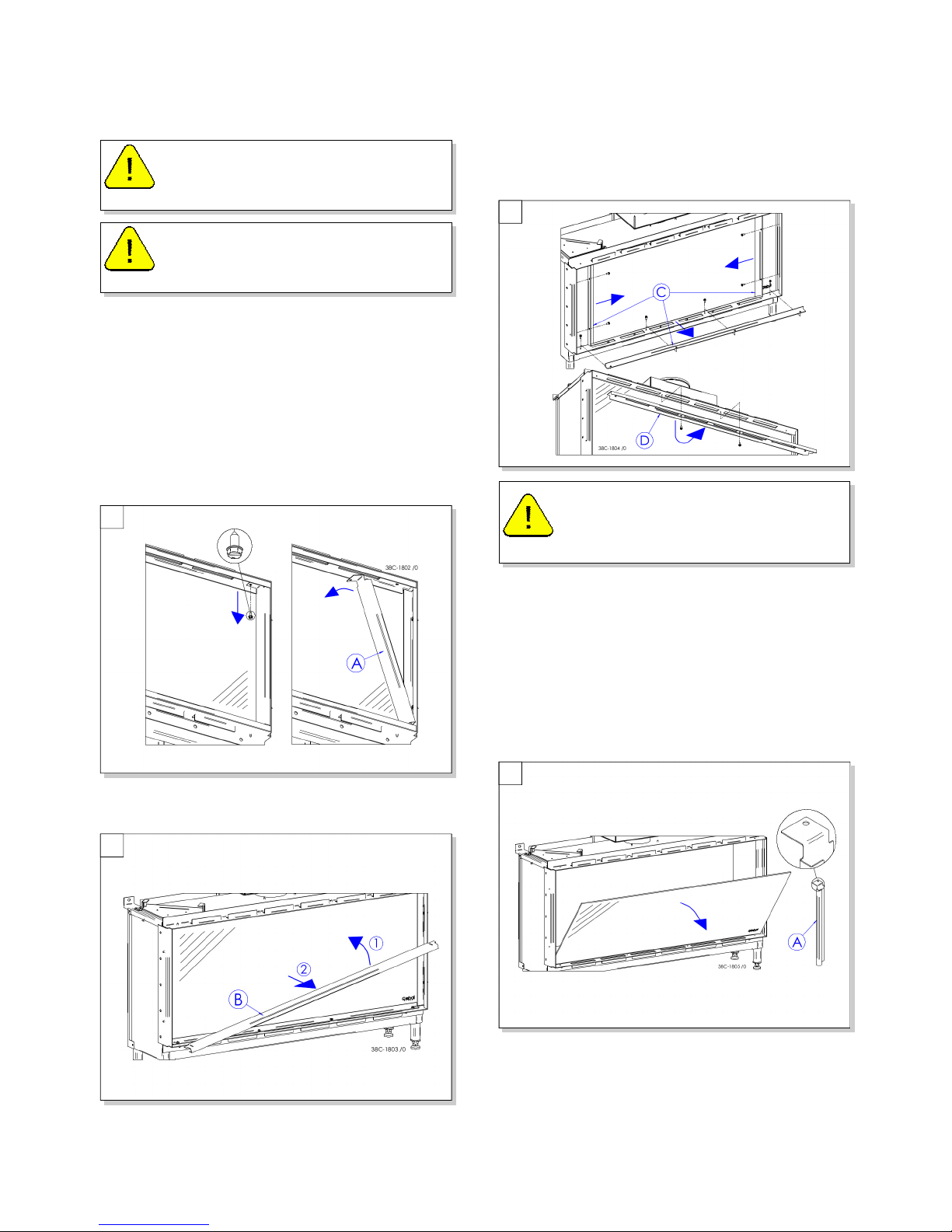
REMOVING THE GLASS PANEL
(See Fig. E1 to E4)
Unscrew the self-tapping screw from the side
decorative strip (A) and remove the side
decorative strip. Repeat this on the other side.
Tilt the lower decorative strip (B) upwards and
remove it from the frame at an angle.
Unscrew the 8 self-tapping screws of the 3
panel clamps (C) from the frame and first
remove the lower clamp strip and then the side
clamp strips of the frame;
Unscrew the 2 central self-tapping screws from
the top of the frame and remove the panel
clamp strip above (D). Tilt the glass panel
towards the front and remove it.
If the glass panel remains stuck, you can use
one of the side decorative strips (A) as a hook in
order to pull the glass panel towards the front.
REFITTING THE GLASS PANEL
After completing the setting of the appliance,
refit the glass panel in the reverse order of
removing the glass panel described above. The
self-tapping screws should not be over
tightened as damage may occur.
Handle the glass panel with care to
avoid damaging it when removing and
reinstalling.
WARNING
Fingerprints on the glass panel will
permanently burn into the glass when
the appliance is used. Clean them off!
WARNING
Before proceeding, you must ensure
the glass panel is supported on the
next step to prevent it from falling out.
CAUTION
E1
E4
E2
E3
Page 18
18
SETTING THE APPLIANCE
The appliance has to be set in such a way that it
works correctly in combination with the flue
system configuration used. The Restrictor Slide
and/or the Air Inlet Guide need to be set as
specified in tables 2, 3 and 4 to match your
installation.
This appliance is suitable for Powervent®. For
more information, see the Powervent®
installation manual.
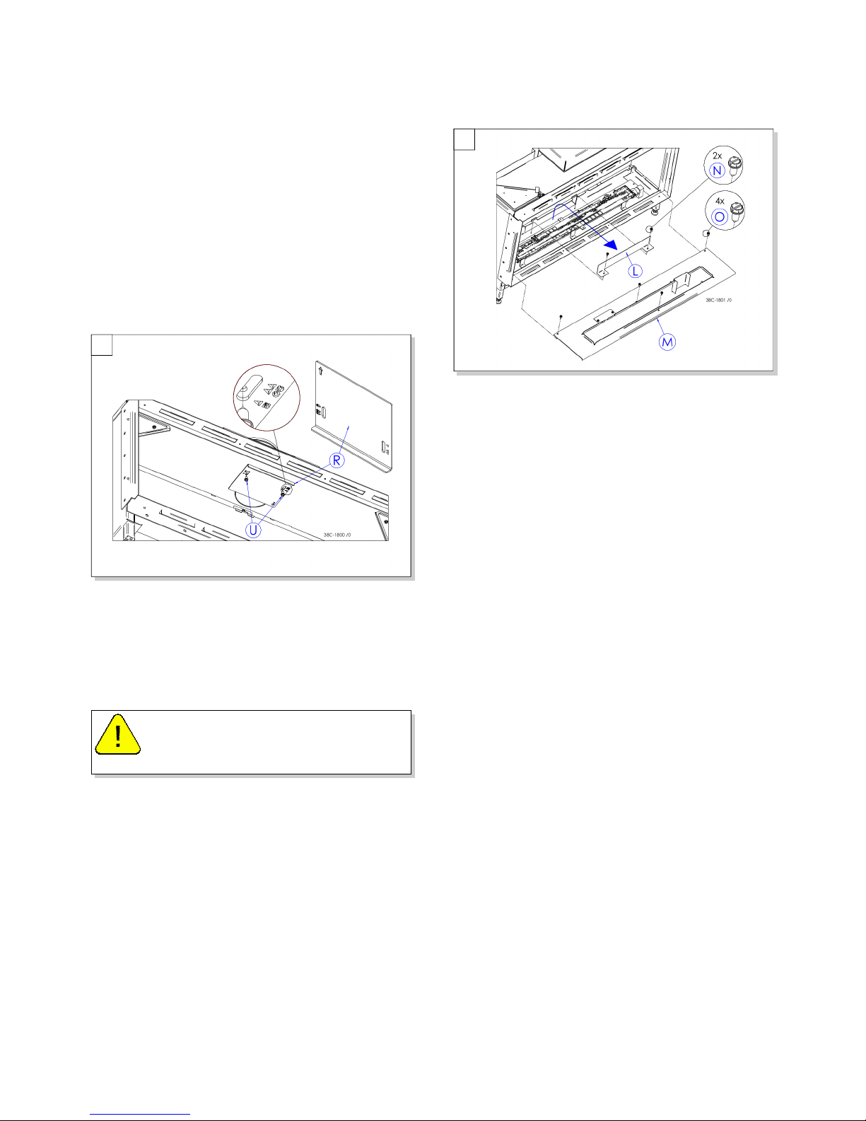
RESTRICTION SLIDE (R)
The baffle (R) is supplied separately. It is
mounted as follows (see Fig. E9):
Unscrew the 2 self-tapping screws (U) which
are already fitted to the combustion chamber.
Place the Restrictor Slide (R). It will partly cover
the hole of the exhaust pipe. Partially tighten
the 2 self-tapping screws (U) by a few turns.
Adjust the position of the restriction slide (R)
using situations B to D in Table 2. The letter of
the position on the restriction slide corresponds
with the letter of the flue configuration in Table
6.
Make sure that the point of the triangle of the
required Restrictor Slide position and the centre
of the self-tapping screw are aligned. Tighten
the 2 self-tapping screws (U).
AIR INLET GUIDE (L)
The Air Inlet Guide (L) is fitted at the factory and
is located at the back of the burner under the
tray (M).
If the instruction in table 2 or 4 says to remove
the Air Inlet Guide, proceed as follows (See Fig
10)
Unscrew the 4 self-tapping screws (O) of the
vermiculite tray (M) and remove the tray (M)
from the combustion chamber
Unscrew the 2 self-tapping screws (N) of the air
inlet guide (L) and remove the air inlet guide.
Refit the 2 self-tapping screws (N) of the air
inlet guide in the combustion chamber.
Replace the tray (M) and re-tighten the 4 selftapping screws (O) around the burner.
When fitting, the arrow on the
Restrictor Slide should point away
from you (See Fig. 9).
CAUTION
E5
E6
Page 19
19
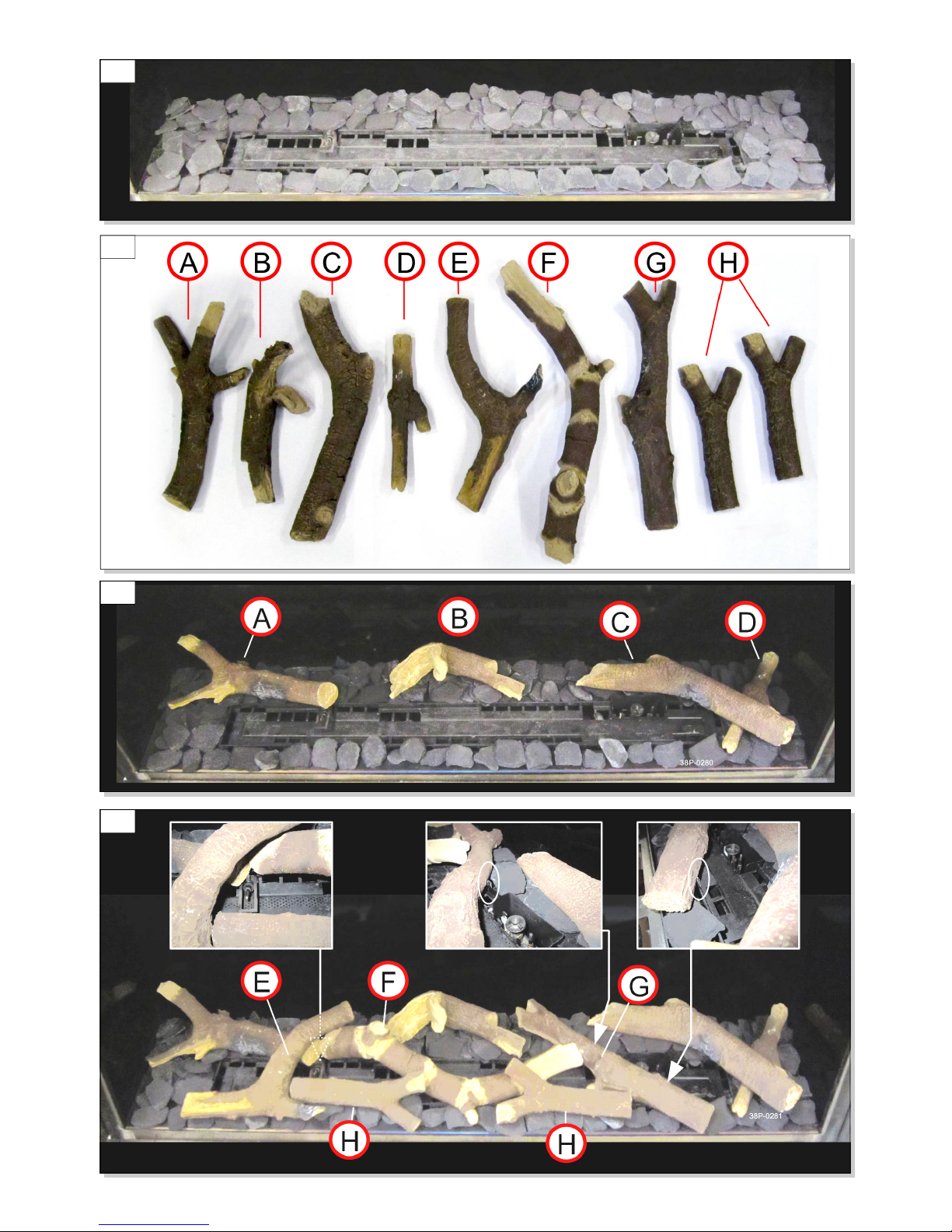
PLACING THE LOG FUEL EFFECT
A fuel effect is supplied with the appliance and
consists of chips and a number of logs.
Fill the vermiculite tray with chips; spread the
chips evenly (See Fig. E9).
Identify the logs A up to H by using Fig. E10. Use
the burn marks on the logs for identification.
Place branches A up to D around the (main)
burner (See Fig. 11).
Place log F on the left against log A so that
thermocouple 2 is free (See Fig. 12).
Place log G against the indicated ridges on the
vermiculite tray (See Fig. 12).
Next position logs E and H (See Fig. 12).
The logs should not completely cover the burner
deck as this will prevent the main burner from
igniting properly. This could result in unsafe
situations, the appliance producing a lot of soot
and a poor flame picture.
Strictly observe the following
instructions to prevent unsafe
situations.
Only ever use the supplied fuel effect
and place it exactly as described
WARNING
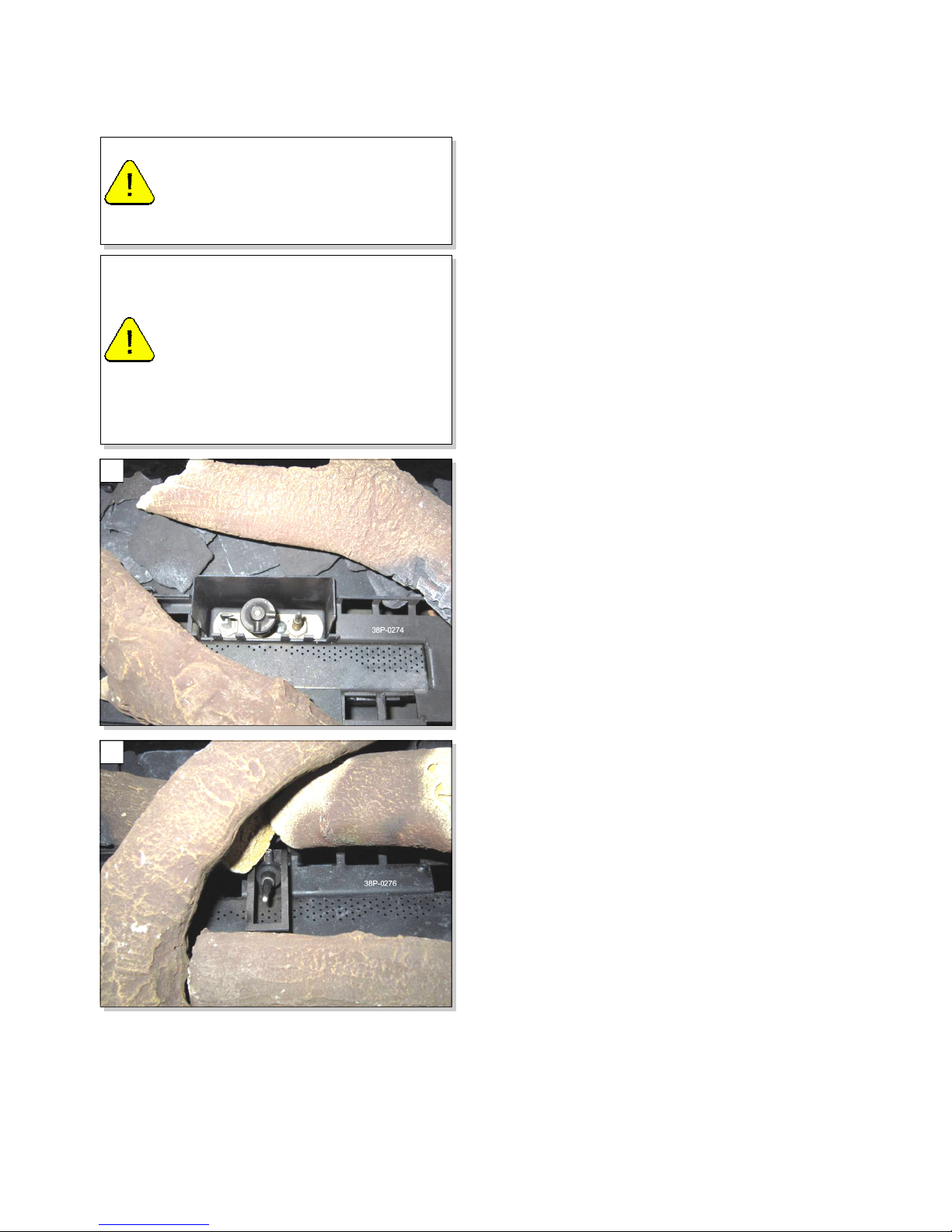
Ensure the pilot burner and the
surrounding space remain free (See
Fig. E7).
Ensure thermocouple 2 and the
surrounding space remain free (See
Fig. E8).
Make sure that the air vents between
the burner and the vermiculite tray
are kept free.
CAUTION
E8
E7
Page 20
20
E9
E10
E11
E12
Page 21
21
WIRELESS REMOTE CONTROL
F
The appliance is supplied with a wireless
remote control.
Controlling the flame height, igniting and
switching off take place through a remote
handset that controls a receiver.
The User Manual describes the operation of the
appliance and how you should use the remote
control.
CONNECTING THE RECEIVER
Your appliance is equipped with electronic
ignition through the remote control.
The receiver should be connected to the
appliance, before installing the batteries.
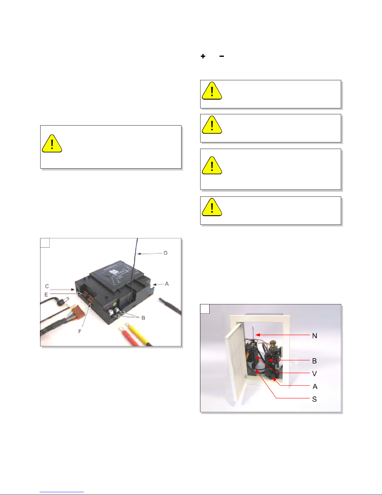
Connect the receiver according to Fig. F1.
Bend the antenna (N) out of the clips and place
it erect (Fig. F2).
The plugs have different sizes that correspond
with the connectors.
The size of the eye corresponds with the size of
the screw, and the colours of eye and screw
correspond too.
After all the connections have been made, insert
the batteries into the receiver unit as follows:
Slide the cover off the Receiver.
Insert 4 new AA
AAAA
AA batteries observing the correct
and orientation as shown in the battery
compartment.
Replace the cover.
Ensure that the wires of thermocouple 2 cannot
come into contact with hot parts
Avoid formation of dust on or in the receiver,
ensure it is covered when performing work.
Place the receiver in its intended holder under
the appliance or in the control hatch according
to Fig. F2.
An optional power adapter is available from
Brilliant to replace the need for batteries. Only
an adapter supplied by Brilliant will guarantee a
proper operation of the receiver.
Do not ignite the appliance before the
flue system connections have been
fully installed. First observe the
procedure described in Section G
Commissioning
WARNING
Use alkaline batteries only.
Rechargeable batteries are not
allowed.
WARNING
Batteries are regarded as "small
chemical waste" and therefore cannot
be disposed of in the household waste.
CAUTION
Do not place the ignition cable over
and/or along metal, stone or concrete
parts: this will weaken the spark. It
must be hanging freely.
CAUTION
Keep the ignition cable at least 10 cm
away from the antenna, in order to
avoid damaging the receiver.
CAUTION
F1
F2
Page 22
22
SETTING THE COMMUNICATION CODE
Prior to putting the appliance into operation, a
communication code must be set between the
remote control and the receiver. If the receiver
or the remote control are replaced, a new code
will have to be set.
Follow the procedure below:
Fit the 9V PP3 battery into the remote handset
as described in the User Manual
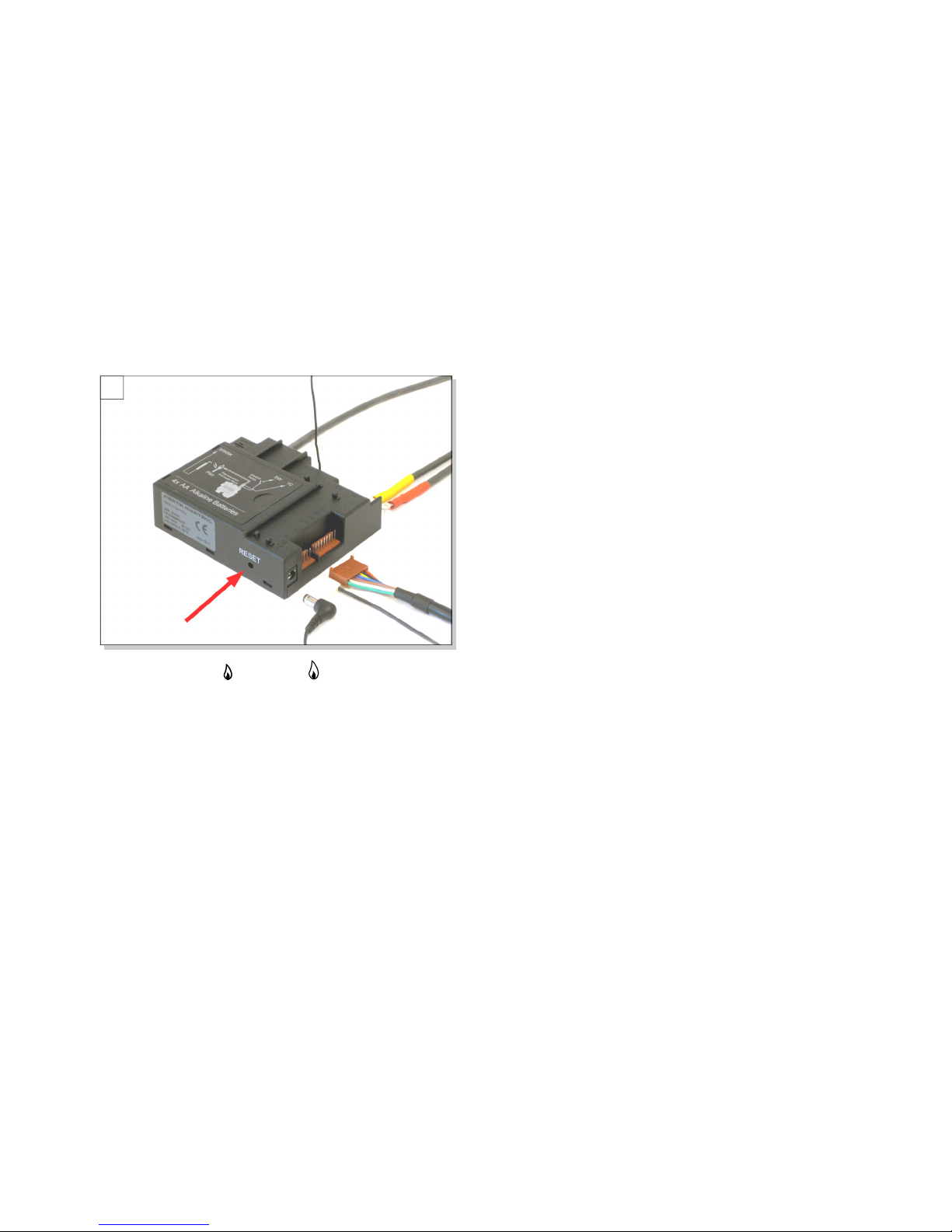
Hold down the reset button on the receiver, until
you hear two consecutive sound signals (See
Fig. F3). After the second, longer signal, let go
of the reset button.
Press the button or button on the remote
control within 20 seconds, until you hear an
extra long sound signal: this is the confirmation
of a correct communication.
F3
Page 23
23
COMMISIONING
In order to check whether the appliance is
working properly and safely, you must perform
the following inspections before the appliance is
used.
GAS SOUNDNESS
Check all the connections for gas soundness.
The gas control can be subjected to a maximum
pressure of 50 mbar.
GAS PRESSURE/LINE-PRESSURE
The burner pressure is set at the factory; see
data plate.
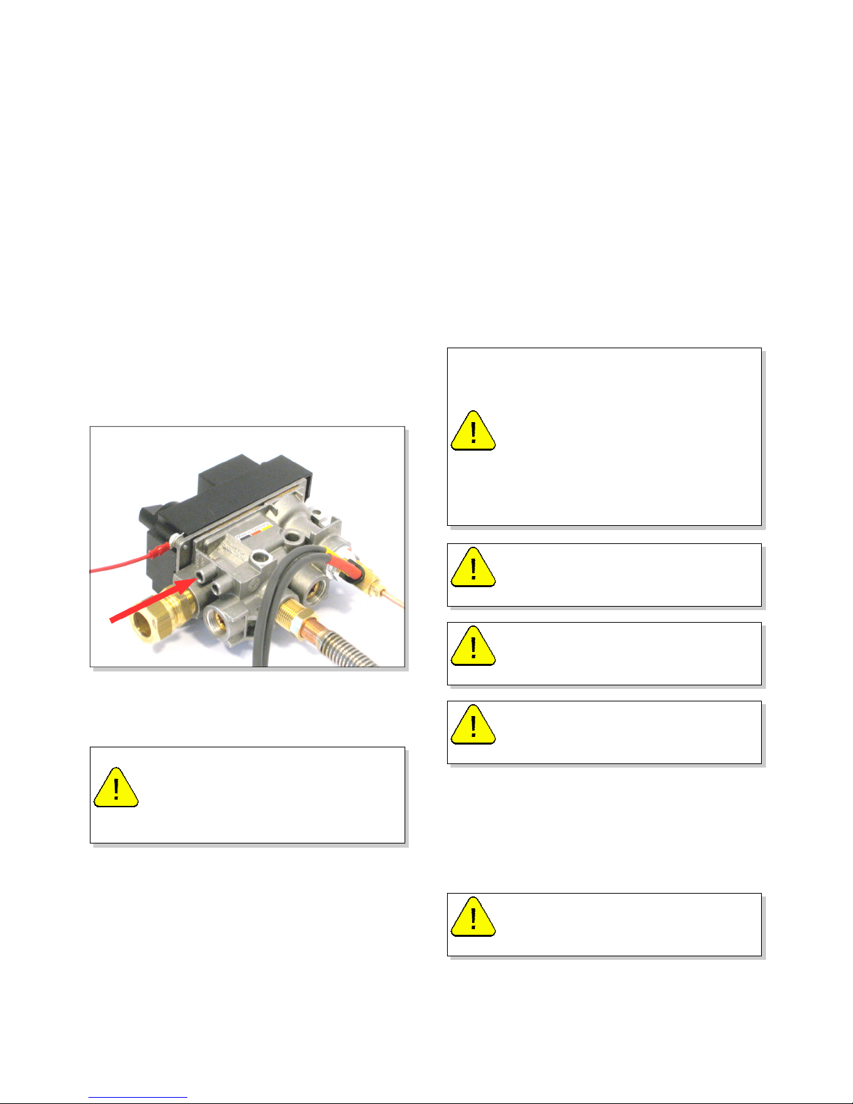
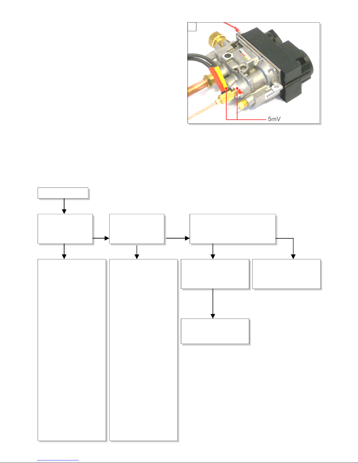
Check the line-pressure; See Fig. G1 for the
measuring nipple on the gas control. Contact
the gas company if the is not correct.
IGNITION PILOT AND MAIN BURNER
For igniting the pilot and main burner, see the
User Manual.
Remove the glass panel as described in Section
E
Start the ignition procedure as described in the
User Manual.
If the pilot flame does not ignite, repeat the
ignition procedure until the pilot burner ignites.
If the pilot doesn’t light after repeated attempts
consult the fault finding diagram in Section H.
After igniting the pilot flame, the main burner
will ignite during the ignition procedure after
approx 25 seconds.
Check whether the main burner continues to
burn.
If the main burner does not continue to burn,
repeat the ignition procedure until the main
burner continues to burn.
If the main burner does not remain alight then
consult the malfunction search diagram in
Section H.
Switch off the appliance and replace the glass
panel as described in Section E
Repeat the ignition procedure a few times and
perform the Main Burner checks below.
MAIN BURNER
The main burner(s) flame must cross the full
burner smoothly and without popping and
continue to burn.
COMMISSIONING AND SERVICING G
After installation, or after work has
been performed, you must ignite the
appliance for the first time without the
glass panel. If necessary, bleed the
gas supply to expel any air.
WARNING
When checking whether the main
burner continues to burn, it is possible
that it still switches off after 22
seconds. This may happen because
the appliance is equipped with a
second thermocouple and the glass
window has not been fitted. In this
case you may presume that the main
burner will continue to burn.
INFO
DO NOT adjust the pilot flame lower
by using the settings on the gas
control.
WARNING
Always wait 5 minutes after the pilot
flame has gone out, before you
reignite the appliance.
WARNING
During the ignition process, you are
not allowed to operate control knob B
on the gas control manually.
WARNING
The pilot burner should ignite the
main burner within a couple of
seconds, and without popping.
WARNING
Page 24
24
After opening the gas valve, the main burner
should burn within a few seconds.
When the gas valve is opened, the motor will
start to run; this is audible.
The flame picture and a good flame transfer can
only be properly judged if the glass panel is
installed.
Use the fault finding diagrams in Section H if
the ignition of the main burner does not comply
with the abovementioned requirements.
FLAME PICTURE
The flame picture can only really be assessed
when the appliance has been burning for
several hours. Volatile components from paint,
materials, etc., which evaporate in the first
hours, will affect the flame picture.
Check whether the flame picture is acceptable.
and consult the fault finding in Section H if it
isn’t acceptable.
MAINTENANCE
The fire must be serviced by a qualified Gas
Gas Gas
Gas
Safe
SafeSafe
Safe registered engineer in accordance
with National and Local Regulations.
www.GasSafeRegister.co.uk
Servicing should be carried out at
least annually, but depending upon site
conditions more frequently.
Check whether the appliance is working
properly and safely.
Check the gas soundness after repair.
After replacing thermocouple 1 you should first
tighten the gland nut by hand and then give it
another quarter turn with a suitable spanner.
If required, clean the following components:
THE PILOT BURNER
The space surrounding the pilot burner.
THE GLASS PANEL.
Remove the deposit on the inside of the glass
panel with a damp cloth or a non-abrasive
detergent such as copper polish or a ceramic
hot plate cleaner.
Replace broken or cracked glass panels.
Inspect the entire flue system.
PARTS
Replacement parts are available from your
supplier or through our mail order service.
Always quote the product code and serial
number when ordering new parts. This
information is on the burner data badge.
HANDOVER TO USER
You must explain to the user how to operate the
appliance. You must give them instructions on
proper operation, the safety measures, the
operation of the remote control and annual
servicing (see the User Manual).
Point out the precautions in the user manual
against unintended ignition by other wireless
remote controls such as car keys and garage
door openers.
WARNING
When using a plaster finish, allow the
chimney breast to dry for at least six
weeks prior to using the appliance in
order to prevent cracks.
DO NOT adjust the pilot flame lower
by using the settings on the gas
control.
WARNING
Always isolate the gas supply to the
appliance during servicing.
WARNING
Remove and replace the glass panel
as described in Section E
CAUTION
Fingerprints on the glass panel will
permanently burn into the glass when
the appliance is used. Clean them off!
WARNING
If necessary, reset the fuel effect set
correctly. See Section E
CAUTION
You must always perform a final
inspection.
CAUTION
Tell the user to close the gas isolation
valve immediately and contact the
installer in case of malfunctions/poor
operation to prevent unsafe situations.
Indicate the location of the gas
isolation valve.
WARNING
Page 25
25
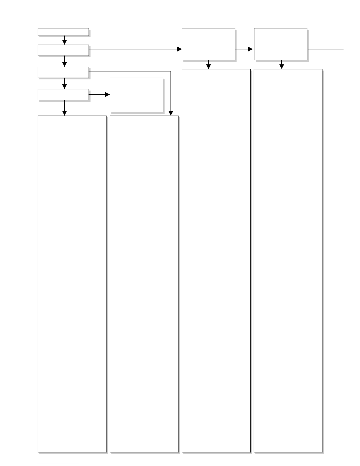
FAULT FINDING - STARTUP CYCLE H
YES
NO
YES
NO
NO
YES
YES
1.01
Does receiver beep?
1.05
Short beeps, 1sec after another, followed
by clicking noise of gas valve opening,
possibly followed by ticking sounds of
ignition attempts.
1.06
Three swift short beeps
(within 1 sec time)
1.08
Remote control system is OK.
Continue with "Fires with
electronic ignition, fault
finding ignition and burning"
1.07
Replace batteries
1.04 Check
All appliances
All appliancesAll appliances
All appliances
- 8 wire cable between receiver
and gas control not
connected, poor contact, or
one wire loose in connector.
(check by pulling wire by
wire).
- Wiring of thermocouple
circuit interrupted, or poor
contact.
Check thermocouple,
thermocouple interrupter
and wiring.
See box 2.05.
- Micro switch on gas control
defective.
Appliances with 2nd
Appliances with 2nd Appliances with 2nd
Appliances with 2nd
thermocouple only
thermocouple onlythermocouple only
thermocouple only
- 2nd thermocouple not cooled
down sufficiently. Wait till
cooled down (voltage < 1.2mV,
measure between black
extension wire and earth).
- Wiring of 2nd couple
interrupted. Check wiring,
see box 2.13.
- Else: receiver damaged,
replace.
1.02
Receiver
ReceiverReceiver
Receiver
- Batteries missing or empty.
Replace by 4 x AA.
When replacing batteries
short beep: no beep: receiver
defective.
Replace by new one.
- Replace rechargeable by
alkaline batteries.
- Communication code
between remote and receiver
has to be (re)set:
Press reset button on
receiver until brief beep
followed by long beep.
Release reset button and
press 'flame low' button on
remote within 20 seconds
- Then 2 short beeps and brief
noise of servomotor to
confirm that communication
code was set successfully.
Remote set
Remote setRemote set
Remote set
- Battery 9V empty (see
indication on display)
Several
SeveralSeveral
Several
- After switching off/going out
the remote set is locked for
120 sec. (older versions 60
sec).
Wait 2 minutes before
reigniting.
Start
StartStart
Start
1.03
One long 5 second beep,
(possibly preceded by 7
short beeps)
When the user starts the appliance for the first
time, point out that;
In order to avoid cracks in a chimney breast
made of stone-like materials or finished with
plaster, it should dry for at least 6 weeks prior
to putting the appliance into operation.
When the appliance is lit for the first time,
volatile components evaporate from paint, and
other constructional materials. This normal and
will wear off after a few hours of use with the
appliance set to the highest level.
The room should be well ventilated during this
initial burn off time.
Give the manual to the user (the manual should
be stored near the appliance).
G1
Page 26
26
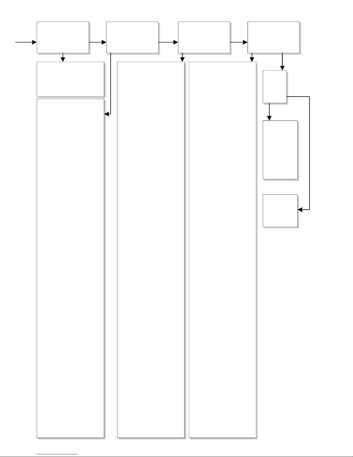
FAULT FINDING: IGNITION AND BURNING
YES
NO
YES
NO
YES
NO
YES
NO
YES
NO
2.04
Check:
Receiver
ReceiverReceiver
Receiver
- Replace missing, weak or
rechargeable batteries (not
enough power to open
thermoelectric valve)
Presence of gas on pilot burner
Presence of gas on pilot burnerPresence of gas on pilot burner
Presence of gas on pilot burner
Check pilot on presence of gas
at normal ignition cycle or in
Manual Mode (turn oval knob on
gas control to MAN and keep
safety shut off valve opened with
a screwdriver) and ignite pilot
with a lighter.
- Pilot flame not on: Step 1
- Pilot flame on: Step 2
Step 1: Pilot has no gas
Step 1: Pilot has no gasStep 1: Pilot has no gas
Step 1: Pilot has no gas
- Gas tap open?
- Gas at gas control (line
pressure at measuring point
on gas control).
- Check presence of gas at
pilot burner, by igniting in
Manual mode:
Turn oval knob on gas control
on MAN, open safety shut off
valve with a screwdriver and
try to ignite pilot with a
lighter.
Not alight, then check the
following:
- Blocking of pilot tube (kink or
dirt)
- Gas flowing out of gas
control?
(by loosening pilot tube at gas
control)
- If not: check adjustment
screw pilot flame (under
black cover): sealing not to be
broken.
Sealing broken: screw should
be fully open.
- If this does not help: replace
gas control.
Step 2: Pilot has gas, but no
Step 2: Pilot has gas, but noStep 2: Pilot has gas, but no
Step 2: Pilot has gas, but no
ignition
ignitionignition
ignition
- Electrode with 90° tip:
bend tip 1mm higher
- Spark too weak (thin and
reddish). Act as if 'no spark'
in box 2.05 and perform
actions described for ignition
cable and ignition electrode.
- Pilot flame too weak (dirty).
Remove injector (remove
gland nut and the pilot tube).
See that it does not fall away.
Clean with compressed air.
Rectify. Retry.
2.03 Only one spark?
2.02 Sparking?
2.01 Can Pilot be lit?
Start
StartStart
Start
2.03a
- Loosen and retighten
earth screw on gas
control.
- If this does not work:
Replace receiver.
2.05 Check:
Ignition cable
Ignition cableIgnition cable
Ignition cable
- Present and connected
- Being free from metal parts
or concrete.
- Too long: cut away all
excessive length at receiver
end, and reconnect.
- Shorting out to earth; replace
ignition cable.
- Spark in wrong position
- Slide rubber sleeve on
ignition cable over ceramic of
electrode.
- Replace electrode if
necessary.
Ignition electrode
Ignition electrodeIgnition electrode
Ignition electrode
- Straight
Straight Straight
Straight electrode:
- Oxidation (roughen electrode
with file or sand paper)
- Position 4 mm from pilot
burner
- Cracks in ceramic (not
always
visible), replace electrode.
Thermocouple circuit
Thermocouple circuit Thermocouple circuit
Thermocouple circuit
interrupted
interruptedinterrupted
interrupted
- Check connection between:
- Thermocouple and
interrupter
- Interrupter and gas control
Is it tight? (hand tight + half a
turn)
- Black wires (yellow/red end)
not (well) connected in
thermocouple interrupter, in
right position on receiver (in
right position)
- Thermocouple broken inside
thermocouple interrupter:
Replace.
- Thermocouple interrupter
defective.
Check by screwing
thermocouple directly in gas
control and ignition in Manual
mode (see 2.04).
Starting procedure
Starting procedureStarting procedure
Starting procedure
After switching off/going out the
remote is locked for 120 sec.
(older versions 60 sec).
Wait 2 minutes before reigniting.
2.07 Check thermocouple
thermocouple thermocouple
thermocouple
system
systemsystem
system
Step 1: Check pilot flame and
Step 1: Check pilot flame andStep 1: Check pilot flame and
Step 1: Check pilot flame and
thermocouple
thermocouplethermocouple
thermocouple
- Pilot flame too small
- Pilot dirty. Rectify (see 2.04)
- Check for pilot gas tube
soundness
- Pilot tube kinks or dirt inside
- Line pressure too low
- Tip not in (correct!) pilot
flame.
Bend into flame.
Step 2: Check circuit for
Step 2: Check circuit forStep 2: Check circuit for
Step 2: Check circuit for
interruptions or short circuiting
interruptions or short circuitinginterruptions or short circuiting
interruptions or short circuiting
- Thermocouple tight in
interrupter
- Interrupter tight in gas
control
- Black wires (yellow/red end)
- Connected to interrupter +
receiver
- Short circuiting at interrupter
Step 3: Check receiver
Step 3: Check receiverStep 3: Check receiver
Step 3: Check receiver
Dismount black-red and -yellow
control cables from receiver and
link together. Ignite fire in
Manual Mode (see 2.04, light
pilot with a lighter):
- Pilot stays on: the receiver is
defective (replace) , and the
rest of the thermocouple
system is OK.
- Pilot goes out: Step 4.
Step 4
Step 4Step 4
Step 4: Check thermocouple
: Check thermocouple : Check thermocouple
: Check thermocouple
and gas control
and gas controland gas control
and gas control
Screw thermocouple directly in
gas control and light in Manual
Mode (see 2.04, light pilot with a
lighter):
- Pilot stays on: Thermocouple
interrupter defective.
- Pilot goes out:
- Thermocouple defective
- Thermo-electric device
defective Go to step 5.
Step 5: Check thermocouple
Step 5: Check thermocoupleStep 5: Check thermocouple
Step 5: Check thermocouple
Check thermocouple by
replacing or by measuring
output voltage (>5mV, with
thermocouple connected). See
Figure G1.
Step 6
Step 6Step 6
Step 6
If thermocouple is not the cause
the thermo-electric device is
defective.
Replace gas control.
8888----Wire black control cable
Wire black control cableWire black control cable
Wire black control cable
- 8-wire cable between
receiver and gas control not
connected.
- Poor contact of connector.
Check for pins on receiver
not being bent.
- One of eight wires loose in
connector.
Check by pulling wire by wire at
both ends of cable.
2.06 Pilot can be lit.
Does it stay alight?
2.08 Does main burner
ignite immediately?
2.09 Ignition procedure
2.09 Ignition procedure2.09 Ignition procedure
2.09 Ignition procedure
- Oval knob on gas control is
on "MAN". Set to "ON" and
restart.
Retarded ignition of main
Retarded ignition of main Retarded ignition of main
Retarded ignition of main
burner
burnerburner
burner
Gas to main burner opens 3-5
seconds after servo motor
operating the gas valve starts
running (sound of motor!). After
this the main burner is to ignite
(at least partially) within 10
seconds and not with a firm
noise WHOOF.
If not: no or delayed cross
lighting of main burner.
Hazardous situation. Stop
ignition procedure straight away
and first check for:
- Position of logs or pebbles
- Burner holes (locally)
blocked. Remove vermiculite
dust.
- Vermiculite missing
- Chips on burner
- Vermiculite not distributed
evenly across burner(s)
PowerVent® (if present)
PowerVent® (if present)PowerVent® (if present)
PowerVent® (if present)
Consult PowerVent®
installation manual how to carry
out the checks below.
Check:
- 230V to fan controller unit
and fan.
- Silicon pressure
measurement hoses
swapped leaking or barred
- Pressure difference set too
high
- Resistance of flue system too
high
adjustment of appliance
damper and air inlet guides)
flue length or number of
bends too large
dirty (e.g. cobwebs)
- Operation of the fan
- Operation of solenoid gas
valve
- Operation of fan controller
unit
- Operation of pressure
measurement gauge
Page 27
27
YES
NO
YES
NO
YES
NO YES NO
YES
NO
2.11 No proper cross lighting
of main burner(s)
Go to box 2.09 and take
actions act as described for
'retarded ignition of main
burner'.
2.13 Check cross lighting main
2.13 Check cross lighting main2.13 Check cross lighting main
2.13 Check cross lighting main
burner and 2nd thermocouple
burner and 2nd thermocoupleburner and 2nd thermocouple
burner and 2nd thermocouple
system.
system.system.
system.
Wiring
WiringWiring
Wiring
- The black and red extension
wire of the 2nd thermocouple
is connected to:
- The 2nd thermocouple (both
wires)
- The receiver (black wire, can
be forgotten during
installation)
- Earth (red wire)
Flame transfer main burner
Flame transfer main burnerFlame transfer main burner
Flame transfer main burner
- Is flame transfer main burner
OK?
Flame must heat 2nd couple
within approx. 18 sec. (after
servomotor starts to run).
If not, check:
- 2nd thermocouple free from
vermiculite or chips
- Placement of wood blocks.
- Burner holes (locally)
blocked.
Remove (vermiculite) dust
- Vermiculite is missing
- Chips on burner
- Lack of combustion air. See
2.15
- Vermiculite not spread evenly
over burner(s).
Voltage 2nd thermocouple
Voltage 2nd thermocoupleVoltage 2nd thermocouple
Voltage 2nd thermocouple
- Measure the voltage of the
2nd thermocouple just before
the appliance turns off.
- Measure between black
extension wire and earth.
Voltage <1,8mV Glass window
Voltage <1,8mV Glass windowVoltage <1,8mV Glass window
Voltage <1,8mV Glass window
mounted!
mounted!mounted!
mounted!
- Flame transfer main burner
too low.
See above. Correct this fault,
before taking further action!!
- Flame suffocates, see 2.15.
Correct, before taking further
action!!
- Burner pressure (too high or
too low)
- 2nd thermocouple defective
(output: 0 mV)
- 2nd thermocouple not
correct position.
Bend into correct position (see
Appendix 3, fig. 43).
- 2nd thermocouple in correct
position.
Bend deeper into flame (on
the condition that flame
transfer and flame picture
are in order!! See 2.17)
Voltage >1,8mV
Voltage >1,8mVVoltage >1,8mV
Voltage >1,8mV
- Receiver defective. Replace.
2.10 Main burner(s)
ignite smoothly and
across the full length
after first ignition by
pilot burner?
2.12 Does appliance
switch off
exactly 22 sec after
servomotor starts
running?
2.15 Check
Gas supply
Gas supplyGas supply
Gas supply
- Supply pressure does not
drop away as main burner (or
other appliance) lights,
causing pilot flame to
shorten.
- Burner pressure (too high or
too low)
Flames suffocating, lack of air.
Flames suffocating, lack of air.Flames suffocating, lack of air.
Flames suffocating, lack of air.
Dancing flames on burner.
- Lack of combustion air.
Check:
- Flue system permissible
- Proper flue terminal used
- Terminal correctly sited on
roof or wall relative to
obstructions.
- Integrity of the flue system
(no interruptions, not
blocked, cobwebs)
- Air inlet guides
- Flue restrictor/damper
- Throttle rings
PowerVent®
PowerVent®PowerVent®
PowerVent®
Check if pressure difference set
too high
See manual for specific
requirements.
Pilot burner
Pilot burnerPilot burner
Pilot burner
- Pilot burner dirty. Weak pilot
flame being drawn away by
flames main burner. Clean
with compressed air.
See 2.04
2.14 Does main burner
go out
after 'some time'?
2.17 Check
Flames: too low
Flames: too lowFlames: too low
Flames: too low
- Supply pressure does not
drop away as main burner or
other appliances in the
building light, causing flames
to shorten.
- Burner pressure (too low)
- False air: Check soundness
glass window gasket /
soundness of the connection
of the glass windows of two /
three sided appliances
(no slots allowed)
Flames: too high
Flames: too highFlames: too high
Flames: too high
- Line pressure
- Burner pressure
Flames: no even distribution/out
Flames: no even distribution/outFlames: no even distribution/out
Flames: no even distribution/out
on part of burner(s)
on part of burner(s)on part of burner(s)
on part of burner(s)
- Position of logs or pebbles.
- Burner holes (locally)
blocked.
Remove vermiculite dust.
- Vermiculite not distributed
evenly across burner(s)
- Adjustment of throttle ring(s)
Remove (vermiculite) dust.
- Vermiculite not distributed
evenly across burner(s)
- Adjustment of throttle ring(s)
Flames: too blue/too yellow or
Flames: too blue/too yellow orFlames: too blue/too yellow or
Flames: too blue/too yellow or
sooting
sootingsooting
sooting
- Air inlet guides
- Flue restrictor/damper
- Throttle rings
Flames: suffocating:
Flames: suffocating:Flames: suffocating:
Flames: suffocating: lack of air
lack of air lack of air
lack of air
You see dancing flames on
burner, seeking for air. See 2.15
Flame picture 'restless'
Flame picture 'restless'Flame picture 'restless'
Flame picture 'restless'
Indication of too much draught.
Check:
- Adjustment of appliance
damper and air inlet guides)
- Vertical flue length allowed
(<12m)
- Window glass not mounted
gas tight
PowerVent®? Check:
PowerVent®? Check:PowerVent®? Check:
PowerVent®? Check:
- Pressure difference set too
high
- Silicon pressure
measurement hoses leaking
Consult PowerVent®
installation manual for more
info.
2.19 Replace
gas control
(thermoelectric valve
does not
shut down
quick enough
because
of some
permanent
magnetism)
2.20 Perfect!
You have a well
functioning
fire
2.18 Can
fire be
switched
off?
2.16 Is flame picture
OK?
Page 28
28
12 03 2013
Brilliant Fires Limited
Thwaites Close
Blackburn BB1 2QQ
England
tel +44 (0)1254 682384
fax +44 (0)1254 672647
www.brilliantfires.co.uk
[email protected]
 Loading...