

Page 1

Home Control
Installation Guide
TWO SWITCHES
Page 2

Please confirm the following:
Welcome!
This short installation guide will
help you upgrade your home
with Brilliant.
It is important that you first
review all of the instructions
to ensure you are comfortable
with the required steps.
If you are unsure about or
uncomfortable with the
installation, go to
brilliant.tech/install for more
instructions, and/or help with
finding a qualified electrician.
Thank you!
The Brilliant Team
Is your circuit 120V?
A 120V circuit is required, and is standard in North
American homes.
Is your wiring up to code, with Neutral and
Ground wires?
Both Neutral and Ground wires are required, and
present in most modern homes. Refer to Steps 5
and 6 for more details about wires.
Are you replacing a single or 3-way/multi-way
switch?
If you are replacing a 3-way/multi-way switch,
meaning that you can control the same light(s)
from more than one switch, you should confirm
that the Brilliant can support your configuration.
Refer to Step 1 for pictures of the supported
configurations.
Do you have the right tools?
A size 2 screwdriver is needed to remove your old
switch, and to install Brilliant.
Is your gang box a standard size?
A gang box is the electrical box in the wall, behind
the light switch. The box must have an interior
width of no less than 91mm, and an interior height
of no less than 70mm. Standard sizes will work.
Page 3

In the Box
10 STEPS
To A Better Home
Warning / Attention
FaceplateBase
It’s important to only
use supplied screws.
x2
8 Wire Nuts 8 Extra Wires
(optional)
(optional)
Installing this product involves handling high voltage wiring.
Each step of the enclosed instructions must be followed
carefully. To avoid fire, personal injury, or death, turn o your
circuit breakers and follow the proper safety precautions
UNSURE ABOUT HANDLING ELECTRICAL WIRING?
L’installation de ce produit requiert la manipulation
de câbles électriques à haute tension. Veuillez suivre
soigneusement les instructions ci-jointe étape par étape.
Afin d’éviter tout risque d’incendie, de blessure, ou de mort,
coupez votre disjoncteur ou coupe-circuit et suivez les
VOUS AVEZ DES DOUTES AU SUJET DE VOTRE CÂBLAGE
TRAVAILLEZ AVEC UN ÉLECTRICIEN QUALIFIÉ.
before proceeding.
CONSULT A QUALIFIED ELECTRICIAN.
consignes de sécurité avant de continuer.
ÉLECTRIQUE?
Page 4
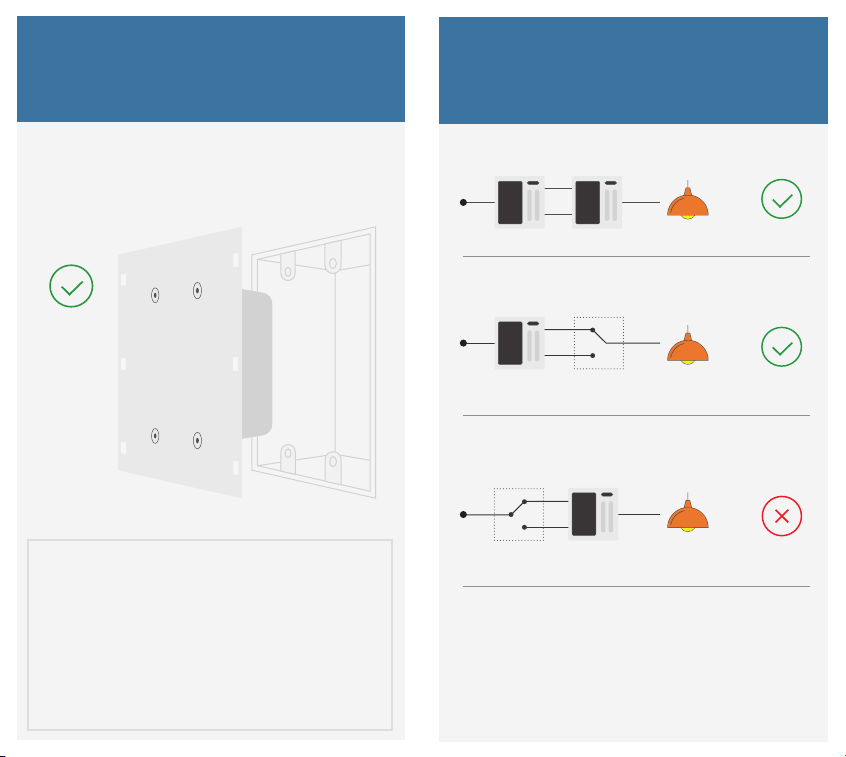
1 Check Compatibility
If your light is controlled by...
2 Switches
Make sure Brilliant is compatible with
the location where you’re installing it.
If the 120V switch you are going to replace
activates a light that other switches also
control (often referred to as 3-way or
multi-way lighting), please find the picture
of your setup on the next pages to confirm
compatibility.
Will work: Two Brilliant controllers
Will work: Brilliant and non-dimming switch
(at either end)
Non-Dimming
Won’t work: Brilliant and dimming switch
(at either end)
Dimming
One circuit shown for simplicity.
See Step 6b, or visit
http://support.brilliant.tech
for more info on wiring multi-way circuits.
Page 5
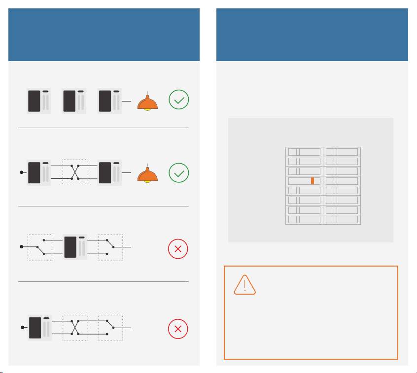
If your light is controlled by...
3 or More Switches
Base
2 Turn O Power
Will work: All Brilliant controllers
(connected through WiFi)
Will work: Brilliant at either end (or both ends) and a
non-dimming switch
Non-Dimming
Won’t work: Brilliant in the middle
Won’t work: Brilliant at the end, with a dimmer
anywhere else
Dimming
Turn the circuit breaker to OFF.
Kitchen
TV Room
Dining
Bedroom
Stairwell
Guest
Patio
Garage
Confirm you’ve turned o the right breaker by flipping your
light switch on and o. If you have turned o the correct
breaker, your light won’t turn on.
Confirmez que le bon coupe-circuit est éteint en utilisant
l’interrupteur à remplacer. Si le bon coupe-circuit est
eectivement éteint, vos lumières ne devraient pas s’allumer.
ON OFF ON OFF
Before Proceeding
Avant de continuer
Page 6

Base
3 Remove Light Switch
4 Identify Each Circuit
Unscrew your old switch cover and
light switch from the wall.
Pull the light switch out from the gang
box, and take pictures of the wires, in case
you need to reference them later. Then,
disconnect the attached wires, and remove
your old light switch.
Single Pole (Go to 5a)
One light switch that controls a light or
set of lights.
3-Way/Multi-Way (Go to 6a)
Two or more light switches that control the
same set of lights.
Note that one switch could be single pole, and the other 3-way/multi-way.
Page 7

Single Pole
Single Pole
5a Identify Your Wires
Ground wire(s) (exposed green or copper)
typically come from the wall box
Line and load wires (black or red)
are connected to your old switch
for each circuit.
x2
x2
Neutral wire(s) (white)
typically come in a bundle and are fastened together
by a wire nut. You must connect all of them.
5b Connect Wires
Black or Red Black or Red
L1 L1L2 L2
N
C C
When connecting
only one circuit,
connect the closest
terminals to ground.
Black White Black
Symbol
Ground
Line/Load*
C
Line/Load*
L1
N
Neutral
*Line and Load are interchangeable.
Brilliant will automatically sense which is which.
Wall Wires
Green/Copper
Black or Red
Black or Red
White
Green or Copper
Page 8

Wires and Wire Nuts
Wires and Wire Nuts are used to connect
two or more wires together, or extend the
length. They are not usually needed, but
you will often use them for Neutral wires.
Select a wire extension from the box.
Match the color of the wires you’re
connecting.
Holding the wires together and parallel,
twist them together. Insert them into a
wire nut, and twist the wire nut clockwise
until secure. Double check by tugging on
the wires.
Base
Single Pole
5c Screws and Wires
Step 1
Place wires in hole as deep as possible.
Step 2
Turn screw clockwise with screwdriver.
Step 3
Tighten until wires are secure. Test by tugging.
Then go to Step 7
Tuck the bundle into the back of the
gang box.
Warning: Short Circuits – Multiple Supply Terminals – Connect All Supply Terminals to the SAME Phase Branch Circuit
Only – Do Not Connect to Dierent Phase Branch Supply Circuits.
Attention: Court Circuits – Lors de L’Utilisation d’un Interrupteur Avec Multiples Terminaux de Raccordement – Connectez
a un Circuit de Phase UNIQUE – Ne Connectez Pas a Plusieurs Circuits de Phase Diérents.
Page 9

3-Way/Multiway
Base
3-Way/Multiway
6a Identify Your Wires
Ground wire(s) (exposed green or copper)
typically come from the wall box
Common (black)
is connected to your old switch
for each circuit.
x2
Traveler wires
(black and red)
are connected to
your old switch
x2
2 travelers for each
3-way circuit
Neutral wire(s) (white)
typically come in a pair and are fastened together
by a wire nut. You must connect all of them.
6b Connect Wires
Red Traveler
Remove 3-way
Sticker
L2 L2
L1 L1
N
White
Symbol
Ground
Common
C
Traveler 1*
L1
N
Neutral
Traveler 2*
L2
*Traveler wires are interchangeable.
Brilliant will automatically sense which is which.
Black Traveler
CC
Black Common
Wall Wires
Remove 3-way
Green or Copper
When connecting
only one circuit,
connect the closest
terminals to ground.
Green/Copper
Black Common
Black Traveler
White
Red Traveler
Sticker
Page 10

Wires and Wire Nuts
Wires and Wire Nuts are used to connect
two or more wires together, or extend the
length. They are not usually needed, but
you will often use them for Neutral wires.
Select a wire extension from the box.
Match the color of the wires you’re
connecting.
Holding the wires together and parallel,
twist them together. Insert them into a
wire nut, and twist the wire nut clockwise
until secure. Double check by tugging on
the wires.
Base
3-Way/Multiway
6c Screws and Wires
Step 1
Place wires in hole as deep as possible.
Step 2
Turn screw clockwise with screwdriver.
Step 3
Tighten until wires are secure. Test by tugging.
Tuck the bundle into the back of the
gang box.
Warning: Short Circuits – Multiple Supply Terminals – Connect All Supply Terminals to the SAME Phase Branch Circuit
Only – Do Not Connect to Dierent Phase Branch Supply Circuits.
Attention: Court Circuits – Lors de L’Utilisation d’un Interrupteur Avec Multiples Terminaux de Raccordement – Connectez
a un Circuit de Phase UNIQUE – Ne Connectez Pas a Plusieurs Circuits de Phase Diérents.
Page 11

7 Install Base
Place wires in the gang box
and attach the Base.
Strain Reliefs
8 Test Lights
Press
Each
Button
Before Proceeding
The strain reliefs are designed to bend to accommodate
dierences in gang box styles and mountings. Some bending of
the strain reliefs is normal, but be careful not to overtighten. Once
the strain reliefs start to bend, you can stop.
Les décharges de traction sont étudiées afin de permettre à
notre produit de s’adapter à diérents types de corets de
branchement. Un certain fléchissement des décharges est
normal, mais prenez garde de ne pas serrer trop fort. Des que les
décharges commencent à fléchir, vous pouvez arrêter de serrer.
Avant de continuer
Turn the circuit breaker back on to
provide power to the Base. Press the white
buttons in the center to turn the lights on
and o. If the lights do not turn on/o, do
not install the Faceplate. Instead, turn the
breaker o, remove the screws, and recheck your wire connections.
Page 12

9 Secure Faceplate
10 Configure Brilliant
Test the Base and secure the Faceplate.
Side Front
Line up the brackets on the Base with the
holes on the Faceplate. Press the Faceplate
into the brackets and slide down until it
clicks. The Faceplate will start up.
Begin Configuration
Tap the “Begin Configuration”
button to start the process,
and follow the prompts.
Connect Wi-Fi
Next, it will ask you to
connect to Wi-Fi, and it is
important to do this so you
can access your other smart
home devices.
Configuration complete
Once the configuration is
complete, you can “Add
Devices” to connect Brilliant to
your supported smart home
devices.
Page 13

Congratulations, you’re
Make your whole
home Brilliant
Once you’ve set Brilliant up, it’s easy to add
more. They’ll automatically set themselves
up and give you all the benefits of Brilliant
throughout your home, including room-to-room
video intercom and more.
For help, educational videos, and additional
product information
visit us: http://support.brilliant.tech
done with installation.
Use the Brilliant App to complete setup.
You can download the Brilliant App on
your iOS or Android device.
Have a more pressing question?
email: support@brilliant.tech
1 switch 3 switches 4 switches
Page 14

Removing and
replacing the display
frame with a new color
Step 1
Before proceeding, remove the Faceplate
from the Base. Put one hand above it, and
grab both sides with the other hand. Then,
slide it up and o.
Step 2
Next, with two hands and your fingers on
the lower edge of the frame, gently pull
slightly down on the rear edge of the frame
until the clips come loose, and the bottom
edge of the frame releases from the display.
Step 3
Pull forward. Once the lower edge comes
loose, continue to rotate the bottom
edge up until you can easily unclip the
upper hooks from the top edge of the
Faceplate.
To attach a new frame, clip the top clips
onto the top edge of the Faceplate and
then rotate it down until the frame is
seated. To ensure the frame is properly
clipped on, first squeeze the lower two
corners and then squeeze the upper
two corners. You can now reattach the
Faceplate to the wall.
6+ replaceable color frame options, such
as ivory, black, and silver, are available at
http://www.brilliant.tech
Side ViewSide View
Page 15

www.brilliant.tech
Contains FCC ID:VPYLB1DX
NOTE: This equipment has been tested and found to comply with the
limits for a Class B digital device, pursuant to part 15 of the FCC Rules.
Operation is subject to the following two conditions: (1) This device may
not cause harmful interference, and (2) this device must accept any
interference received, including interference that may cause undesired
operation. These limits are designed to provide reasonable protection
against harmful interference in a residential installation. This equipment
generates, uses and can radiate radio frequency energy and, if not
installed and used in accordance with the instructions, may cause harmful
interference to radio communications. However, there is no guarantee that
interference will not occur in a particular installation. If this equipment
does cause harmful interference to radio or television reception, which
can be determined by turning the equipment o and on, the user is
encouraged to try to correct the interference by one or more of the
following measures:
—Reorient or relocate the receiving antenna.
—Increase the separation between the equipment and receiver.
—Connect the equipment into an outlet on a circuit dierent from that to
which the receiver is connected.
—Consult the dealer or an experienced radio/TV technician for help.
FCC CAUTION
Changes or modifications not expressly approved by the party
responsible for compliance could void the user’s authority to operate
the equipment. This transmitter must not be co-located or operated in
conjunction with any other antenna or transmitter.
510-00002 REV8
 Loading...