


INVERTER
SWIMMING POOL HEAT PUMP
USER MANUAL
Illustrative photo
i
Read the instructions
EN
VERZE 8. 6. 2017 / REVIZE: 3. 11. 2017

2
Thank you to choose the Inverter swimming pool heat pump for your pool heating, it will
heat your pool water and keep the constant temperature when ambient temperature at
-10°C to 35°C.
Regulation (EU) n° 517/2014 of 16/04/14 on fluorinated greenhouse gases and repealing
Regulation (EC) n° 842/2006

3
ATTENTION: This manual includes all the necessary information with the use
and installation of your heat pump .
1. The installer must read the manual and attentively follow the instruction in implementation
and maintenance.
2. The installer is responsible for the installation of the product and should follow all the instructions
of the errors due to the installation that disobey the manual guideline. Any use that is without
conformity at the origin of its manufacturing will be regarded as dangerous.
WARNING : Please always empty the water in the heat pump during winter time or when
the ambient temperature drops below 0°C, or else the Titanium exchanger will be
damaged because of being frozen ,in such case ,your warranty will be lost.
WARNING : Please always cut the power supply if you want to open the cabinet to reach inside
the heat pump, because there is high voltage electricity inside.
WARNING : Please well keep the display controller in a dry area ,or well close the insulation
cover to protect the display controller from being damaged by humidity.
Index
1. Specification ......................................................................................................................................... 4
2. Dimension ..............................................................................................................................................7
3. Installation ............................................................................................................................................. 8
4. Adjust the by-pass kit ........................................................................................................................ 10
5. Initial operation ................................................................................................................................ 10
6. Controller Operation ........................................................................................................................ 12
7. Operation logic ................................................................................................................................ 15
8. Malfunction and Trouble shooting ................................................................................................. 16
9. Electrical Wiring ............................................................................................................................... 18
10. Maintenance .................................................................................................................................... 19
11. Exploded view .................................................................................................................................. 20

4
1. Specification
Model XHPFD 80 E XHPFD 100 E XHPFD 140 E
* Performance at Air 27°C, Water 27°C, Humidity 80%
Heating (Max./Std./Min.) kW - 10-2,3 -
Power consumption (Std.) kW - 1,52-0,18 -
C.O.P. (Std.) - 13-6,6 -
* Performance at Air 15°C, Water 26°C, Humidity 70%
Heating (Max./Std./Min.) kW - 7,1-1,9 -
Power consumption (Std.) kW - 1,4-0,25 -
C.O.P. (Std.) - 7,5-5,1 -
When water flows m
3
/h - 3.00 -
Voltage 220 ~ 240 V/50 Hz/1 PH
Std. Current Input A 3,7 4,6 5,4
Maximum Current A - 6,65 -
Minimum fuse A 18 18 18
Water in-out connection mm 50
Fan quantity 1
Ventilation type Horizontal
Compressor brand GMCC GMCC GMCC
Compressor type DC inverter Rotary
Noise level at 1m dB(A) 40-52 40-52 40-52
Coolant (R410a) kg 1,05 1,05 1,05
GWP 2088 2088 2088
CO2 Ekvivalent - tun 2,19
Net dimension mm 1045 x 415 x 695 1045 x 415 x 695
Net weight kg 65 65 78
Packing dimension mm 1140 x 430 x 745 1140 x 430 x 745
Gross weight
kg
70 77 83
* Above data may be modified without notice.
* Obsahuje fluorované skleníkové plyny

5
Model XHPFD 160 E XHPFD 210 E XHPFD 260 E
* Performance at Air 27°C, Water 27°C, Humidity 80%
Heating (Max./Std./Min.) kW 17-3,8 - -
Power consumption (Std.) kW 2,54-0,29 - -
C.O.P. (Std.) 13-6,7 - -
* Performance at Air 15°C, Water 26°C, Humidity 70%
Heating (Max./Std./Min.) kW 11,5-3 - -
Power consumption (Std.) kW 2,2-0,37 - -
C.O.P. (Std.) 8.2-5.2 - -
When water flows m
3
/h 5.00
Voltage 220 ~ 240 V/50 Hz/1 PH
Std. Current Input A 7,2 9 11,9
Maximum Current A 11,31 25 32
Minimum fuse A 31
Water in-out connection mm 50
Fan quantity 1 2
Ventilation type Horizontální
Compressor brand MITSUBISHI MITSUBISHI PANASONIC
Compressor type stejnosměrný, se střídačem, rotační
Noise level at 1m dB(A) 41-56 41-56 41-56
Coolant (R410a) kg 1,7 1,7 1,7
GWP 2088 2088 2088
CO2 Ekvivalent - tun 3,55
Net dimension mm 1070 x 410 x 850
Net weight kg 95 - 130
Packing dimension mm 1140 x 430 x 990 1150 x 450 x 1360
Gross weight
kg
110 - 142
* Above data may be modified without notice.
* Obsahuje fluorované skleníkové plyny

6
Model XHPFD 260 EII XHPFD 350 E XHPFD 350 EII
* Performance at Air 27°C, Water 27°C, Humidity 80%
Heating (Max./Std./Min.) kW 26-13 33-16,5 33-6,5
Power consumption (Std.) kW 2,56 3,26 3,26
C.O.P. (Std.) 7,6 7, 6 7,6
* Performance at Air 15°C, Water 26°C, Humidity 70%
Heating (Max./Std./Min.) kW 20-10 25-12,5 25-12,5
Power consumption (Std.) kW 2,67 3,34 3,34
C.O.P. (Std.) 5,6 5,6 5,6
When water flows m
3
/h
Voltage 380 V/50 Hz/3 PH 220 ~ 240 V/50 Hz/1 PH 380 V/50 Hz/3 PH
Std. Current Input A 5,1 14,9 6,4
Maximum Current A 15 40 18
Minimum fuse A
Water in-out connection mm 50
Fan quantity 2
Ventilation type Horizontální
Compressor brand PANASONIC
Compressor type stejnosměrný, se střídačem, rotační
Noise level at 1m dB(A) 52 52 52
Coolant (R410a) kg
GWP
CO2 Ekvivalent - tun
Net dimension mm 1050 x 430 x 1215
Net weight kg 130 145 145
Packing dimension mm 1150 x 450 x 1360
Gross weight
kg
142 157 157
* Above data may be modified without notice.
* Obsahuje fluorované skleníkové plyny

7
2. Dimension
XHPFD 100 E
XHPFD 160 E

8
3. Installation
(1) The heat pump unit must be installed by professional technicians .otherwise unit may be
damaged or body injured, even dead
(2) The unit is designed for outdoor location with good ventilation. Recirculation of cold
discharge air back into evaporator coil will greatly reduce heating capacity and efficiency
of the unit, which will void the compressor warranty.
(3) The unit can be installed almost anywhere in the outdoors. To get a good performance, it
needs to meet the three factors :
a) Good ventilation
b) Stable and reliable power supply
c) Recycled water system
The difference from gas water heater, it should not bring environmental pollution or have
the installing problems in-windy areas.
(4) The unit should not be installed in a limited air ventilation area ,or placed in a bush where
it will block the air inlet .
These location deny the unit of a continuous source of fresh air .When seasons changing, it
may stick leaves on the evaporator coil , thereby reducing its efficiency and impact of its
service life .
(5) For indoor installation, please consult more instruction from technicians.
(6) When install a bypass, it should be not exceed 30% of nominal flow rate.
(7) Must make Water level higher than the circulation pump location.
(8) Below picture show the minimum required distance on each side of pool heat pump unit.
(9) Typically, the pool heat pump unit should be installed aside the pools, less than 7.5 meters
distance.
(10) To get the best heat exchange of heat pump unit, it should be matched the normal rate of
water flow recommended in specification sheet.
(11) It is required to increase the discharge pipe to prevent freezing in cold season, to put T
fitting and ball valve to facilitate changing the water in winter or emptying the water out
of system to prevent freezing when HP stop operating at the ambient temperature below
zero ,otherwise the unit may be damaged .
(12) It is suggested to install the quick adapter in front of water in-out connection, which could
discharge water easily to prevent water freezing, and be convenient for maintenance and service.
(13) When unit running ,there will be some condensation water discharged from the bottom,
please hold the drainage nozzle (accessory ) into the hole and clip well ,and then connect
a pipe to drain the condensation water out.

9
(14) If water pressure is over 10 KPA, or water flow rate is more than 11 cubic meters through
heat exchanger, it is necessary to install the by-pass pipe in water system.
(15) Installation illustration
NOTE: The factory only provides the heat pump unit. The other items in the
illustration are necessary spare parts for the water system which are provided
by users or installers.
ATTENTION: Please follow these steps when operating the first time :
1. Open the derivation valves for charge water and close the valve (direct)
2. Make sure that the pump and the water-in pipe have been filled with water
3. Start the unit
(16) The location of chemical’s instruction to your system is also critical to the heater’s life.
If an automatic chlorinator or brominates is used, it must be located downstream
of the heater.
A trap must be installed between the chlorinator and the heater to prevent chlorine return
into the heat pump. (See below pictures)
A. Bypass connection
1. Sump
2. Filter
3. Return valve
4. Return valve
5. Water treatment
6. Pump
B. Series connection (in-line)
7. Sump
8. Filter
9. Return valve
10. Water treatment
11. Pump
2.
4.
1.
3.
5.
6.
8.
11.
7.
9.
10.
A.
B.
A Swimming pool
B Filter
C Pump
D Heat pump
A
B
D
C

10
4. Adjusting the bypass
Use the following procedure to adjust the bypass:
• fully open all three valves
• slowly close valve 1 until the water pressure is increased by approximately 100 to 200 g
• Close valve 3 approximately half-way to adjust the gas pressure in the cooling system
• If the display shows „ON“ or error code EE3, close step by step the valve 2, to increase
water flow and stop when the code disappear.
Optimal operation of the heat pump occurs when the cooling gas pressure is 22 ±2 bar.
This pressure can be read on the pressure gauge next to the control heat pump panel. Under
these conditions the water flow through the unit is also optimal.
Note: Operation without a bypass or with improper bypass adjustment may result in sub-optimal heat
pump operation and possibly damage to the heat pump, which renders the warranty null and void.
5. Initial operation
Note: In order to heat the water in the pool (or hot tub), the filter pump must be running to
cause the water to circulate through the heat pump. The heat pump will not start up if the
water is not circulating.
After all connections have been made and checked, carry out the following procedure:
1. Switch on the filter pump. Check for leaks and verify that water is flowing from and to the
swimming pool.
2. Connect power to the heat pump and press the On/Off button on the electronic control
panel. The unit will start up after the time delay expires (see below).
3. After a few minutes, check whether the air blowing out of the unit is cooler.
4. When turn off the filter pump , the unit should also turn off automatically, if not, then
adjust the flow switch.
5. Allow the heat pump and the filter pump to run 24 hours a day until the desired water
temperature is reached. The heat pump will stop running at this point. After this, it will
restart automatically (as long as the filter pump is running) whenever the swimming pool
water temperature drops 2 degree below the set temperature.
BYPASS
6
Discharge connection
7 8
1
2
3
4 5
1. Valve 1
2. Valve 2
3. Valve 3
4. Outside
5. Inside
6. Pump
7. To swimming pool
8. From the filter

11
Depending on the initial temperature of the water in the swimming pool and the air temperature,
it may take several days to heat the water to the desired temperature. A good swimming pool
cover can dramatically reduce the required length of time.
Water Flow Switch:
It is equipped with a flow switch for protecting the HP unit running with adequate water flow
rate .It will turn on when the pool pump runs and shut it off when the
pump shuts off. If the pool water level higher than 1 m above or below the heat
pump’s automatic adjustment knob, your dealer may need to adjust its initial
startup.
Time delay
The heat pump has a built-in 3-minute start-up delay to protect the circuitry and avoid excessive
contact wear. The unit will restart automatically after this time delay expires. Even a brief
power interruption will trigger this time delay and prevent the unit from restarting immediately.
Additional power interruptions during this delay period do not affect the 3-minute duration of
the delay.
Condensation
The air drawn into the heat pump is strongly cooled by the operation of the heat pump for
heating the pool water, which may cause condensation on the fins of the evaporator. The
amount of condensation may be as much as several liters per hour at high relative humidity.
This is sometimes mistakenly regarded as a water leak.
Pressure gauge display (R410A
Examine the pressure gauge which indicates the refrigerant gas pressure of the unit, the below
table shows the normal value of the gas pressure (R410A) when the machine is in power off or
running conditions.
Unit Condition Power Off
Ambient (°C) -5 ~ 5 5 ~ 15 15 ~ 25 25 ~ 35
Water temp (°C) / / / /
Pressure gauge (Mpa) 0,68 ~ 0,93 0,93 ~ 1,25 1,25 ~ 1,64 1,64 ~ 2,1
Unit Condition Running
Ambient (°C) / / / / /
Water temp (°C) 10 ~ 15 15 ~ 20 20 ~ 25 25 ~ 30 30 ~ 35
Pressure gauge (Mpa) 1,3 ~ 1,8 1,5 ~ 1,9 1,6 ~ 2,3 1,9 ~ 2,8 2,1 ~ 3,5

12
6. Controller Operation
6.1
button
Press
to start the heat pump unit, the LED display shows the desired water temperature
for 5 seconds, then shows the inlet water temperature and the operation mode.
Press
to stop the heat pump unit and show “OFF”
During the parameter checking and setting, press the
to quick-exit and save the current
setting.
Press
again to turn on/off the machine.
6.2
button
It will be under function only with other button.
6.3
and
button
Clock/unclock the display:
Hold
and for 5 seconds to lock/Unlock the display.
Water temperature setting:
Press
or
to set the water temperature directly.
6.4
Symbol of heating, the light will be on when it is in operation.
When defrosting, the light will flash.
6.5
Symbol of cooling, the light will be on when it is in operation.
6.6
Symbol of automatic stop when it is light.
6.7
Symbol of automatic start when it is light.
6.8 Parameter checking
Press
first, then press to check the “ User parameter from d0 to d11.

13
Parameter code Condition Range Remarks
d1 IPM mould temperature 0-120 °C
Real testing value
d1 Inlet water temperature -9-99 °C
d2 Outlet water temperature -9-99 °C
d3 Ambient temperature -30 °C-70 °C
d4 Gas return temperature -30 °C-70 °C
d5 Pipe temperature -30 °C-70 °C
d6 Gas exhaust temperature 0-C5 °C (125 °C)
d7 Steps of electronic expansion valve 0-99 N*5
d8
Compressor operating frequency
Powerful: 65, 70, 75 Hz
Smart: 50, 55, 60 Hz
Silent: 30, 35, 40, 45 Hz
0-99 Hz
Real testing value
d9 Compressor current 0-30 A
d10 Current fan speed 01200RPM Real testing value
d11 Error code for last time All error code
6.9 Press first, then press to check/adjust the “ User parameter from P1 to P7
Parameter code Condition Range Default Remarks
P1 Working mode 01 1 1 Heating mode, 0 cooling mode
P2 Timer on/o 01 0
1 Timer on/o is under function,
0 Timer on/o is out of function
(The setting of P4 and P5 won’t
work)
P3 Water pump 01 0
1 Always running,
0 Depends on the running
of compressor
P4 Current time HH:MM 00:00 023:059
P5 Timer on HH:MM 00:00 023:059
P6 Timer o HH:MM 00:00 023:059
P7
Inlet water temp. correction
9~9 0 Default setting: 0
ATTENTION: If the current time is in the range of time OFF, the heat pump will be turn
OFF automatically after setting the time of automatic start and the time of
automatic stop. Whereas the heat pump will operate normally.
14
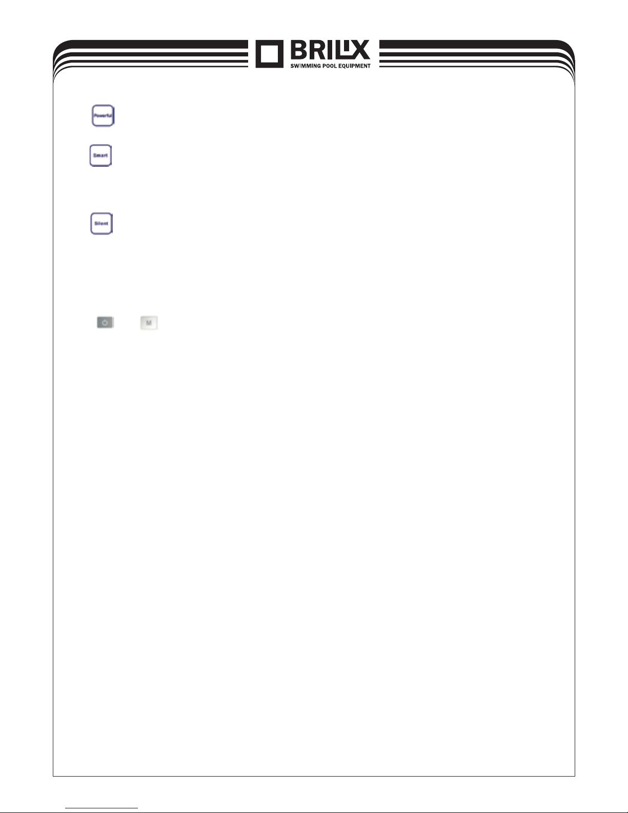
6.10
Press this button, the light will be flash, the heat pump will operate in ‘Full output’ only.
6.11
While you choose the Smart, the heat pump will just operate in ‘Medium output’ and ‘Full output’.
When in ‘Medium output’, the light of Smart will flash.
When in ‘Full output’, the lamp of Smart is lighting, the lamp of Powerful will be flash.
6.12
While you choose the Silent , the heat pump will just operate in ‘Medium output’ and ‘Small
output’.
When in ‘Small output’, the light of Silent will flash.
When in ‘Medium output’, the lamp of Silent is lighting, the lamp of Smart will be flash.
6.13 System reset function
Press
and in 10s, the system will reset and display “0000” on the controller.

15
7. Operation logic
7.1 The heating operation logic
Working status Working mode Water in temperature Heat pump working level
1
Start-up of heat
pump
Smart
<
=
setT - 1 Powerful
2 setT - 1 < a < setT + 1 Smart
3
>
=
setT + 1 Standby
4
Silent
<
=
setT - 1 Smart
5 setT - 1 < a < setT + 1 Silent
6
>
=
setT + 1 Standby
7
Powerful
< setT + 1 Powerful
8
>
=
setT + 1 Standby
9
Re-start to heat
water in standby
status
Smart
> setT - 1 Standby
10 setT - 3 < a
<
=
setT - 1 Smart
11
<
=
setT - 3 Powerful
12
Silent
> setT - 1 Standby
13 setT - 3 < a
<
=
setT - 1 Silent
14
<
=
setT - 3 Smart
15 Powerful
<
=
setT - 1 Powerful
7.2 The Cooling operation logic
Working status Working mode Water in temperature Heat pump working level
1
Start-up of heat
pump
Smart
<
=
setT - 1 Standby
2 setT - 1 < a < setT + 1 Smart
3
>
=
setT + 1 Powerful
4
Silent
<
=
setT - 1 Standby
5 setT - 1 < a < setT + 1 Silent
6
>
=
setT + 1 Smart
7
Powerful
> setT + 1 Powerful
8
<
=
setT + 1 Standby
9
Re-start to cool
water in standby
status
Smart
>
=
setT + 1 a < setT + 3 Smart
10
>
=
setT + 3 Powerful
11
Silent
>
=
setT + 1 a < setT + 3 Smart
12
>
=
setT + 3 Powerful
13
Powerful
>
=
setT + 1 Powerful
14 Standby
NOTE :
setT = Setting water temperature
setT-1 = less 1°C than Setting temperature
setT+1= more 1°C than Setting temperature
NOTE:
Water temperature rise k Water temperature drop

16
7.3 The operating logistic of shift between Silent, Smart and Powerful mode: the default
setting in factory is in Smart operating mode.
If you choose the Silent, the heat pump will just operate at silent and smart mode.
If you choose the Smart mode, the heat pump will just operate at Smart and Powerful mode.
If you choose the Powerful mode, the heat pump will just operate at powerful mode.
8. Malfunction and Trouble shooting
8.1 Error code display on LED wire controller
Faults
Remark
Reason Solution
Sensor error inlet water temperature PP01 The sensor is open or short circuited Check or replace the sensor
Sensor error outlet water temperature PP02 The sensor is open or short circuited Check or replace the sensor
Sensor error heating condenser PP03 The sensor is open or short circuited Check or replace the sensor
Sensor error gas return PP04 The sensor is open or short circuited Check or replace the sensor
Sensor error ambient temperature PP05 The sensor is open or short circuited Check or replace the sensor
Sensor error gas at the condenser output PP06 The sensor is open or short circuited Check or replace the sensor
Frost protection in winter PP07
Ambient temperature or water inlet temperature
is too low
Protection from cold temperatures PP08
Ambient temperature or water inlet temperature
is too low
Cooling pipe temperature too high protection PP10 Check the system
High pressure error EE01
1. Too much refrigerant,
2. Too high water or environment temperature,
3. Operating frequency is too high,
4. Motor failure
1. Drain excess refrigerant,
2. Clean air heat exchanger,
3. Check and reconnect the electrical cables
from the high pressure switch,
4. Replace the high pressure switch.
Low pressure error EE02
1. Not enough refrigerant,
2. Insufficient flow,
3. Dirty filter,
4. EEV failure,
5. Fan motor fault,
6. Low pressure switch failure
1. Check that there are no gas leaks, have a
specialised company change add refrigerant,
2. Clean air heat exchanger,
3. Replace the filter,
4. Check and reconnect the electrical cables
from the low pressure switch,
5. Replace the low pressure switch
Impaired water flow
EE03or
„ON“
Weak flow of water, flow in the wrong direction
or flow switch failure
1. Make sure the water flow is sufficient
2. Make sure the water flow switch is connected
correctly
3. Check the wiring to the water flow switch
4. Replace with a new water flow switch.
The water temperature is heated above the
temperature in heating mode
EE04 The water flow is insufficient, or there is no water
1. Check and repair pump
2. Clean water pipe system
3. Check the water flow switch
Failure of exhaust gas temperature sensor EE05
1. Defrosting is not working properly,
2. Insufficient gas,
3. The throttle device is jammed,
4. Weak flow of water
1. Manual defrost,
2. Refill the gas,
3. Replace the throttle device
4. Check the water pump
Regulator fault EE06
1. Electrical connection is not working properly
2. Regulator fault
1. Check or replace cable
2. Restart power
3. Replace the regulator
Compressor check EE07 The compressor downstream is too high
Turn off the heat pump for 10 seconds and
then turn it on again
Communication error between the cable
controller and the instrument panel
EE08
1. Bad cable connection,
2. Control error
1. Check or replace the connecting cable,
2. Turn off the heat pump for 10 seconds and
then turn it on again, or replace the controller
Communication error between the instrument panel and control panel
EE09 Bad cable connection
Reconnect the cables or replace
the instrument panel
Protection against high voltage EE10 The voltage is too high. Check the power supply
IPM module protection EE11 Bad or corrupted data
Turn off the heat pump for 10 seconds and
then turn it on, or replace the instrument
panel
Protection against too low voltage EE12 The voltage is too low.
Check the power supply
Protection against overcurrent EE13
The voltage is too low,
the heat pump is overloaded
1. Check the power
2. Make sure the water temperature is not
too high

17
Faults
Remark
Reason Solution
IPM module output circuit temperature
sensor failure
EE14 The sensor output is abnormal Check the instrument panel or replace
Protection against excessively high IPM
module temperatures
EE15 Check the instrument panel or replace
Protection of PFC module EE16 Check the instrument panel or replace
DC fan error EE17 Check the instrument panel or replace
IPM module input circuit temperature sensor
failure
EE18 Check the instrument panel or replace
Protection against excessively high PFC
module temperatures
EE19 Check the instrument panel or replace
Electrical power failure EE20 The supply voltage is too variable Check the instrument panel or replace
Software check error EE21 The compressor runs outside of preset steps Check the instrument panel or replace
Current detection circuit fault EE22 Abnormal amplification of the output voltage Check the instrument panel or replace
Compressor switch fault EE23 Check the instrument panel or replace
Ambient temperature thermometer control
unit failure
EE24
Compressor phase error EE25
1. Badly connected wiring,
2. Connection of one or two phases
Monitor the controller
Defrosting symbol, heater check is lit
Defrosting of glass
8.2 Other Malfunctions and Solutions (No display on LED wire controller)
Malfunctions Observing Reasons Solution
Heat pump is
not running
LED wire controller
no display.
No power supply
Check cable and circuit breaker if
it is connected
LED wire controller.
displays the actual time.
Heat pump under standby status Startup heat pump to run.
LED wire controller
displays the actual
water temperature.
1. Water temperature is reaching
to setting value, HP under constant temperature status.
2. Heat pump just starts to run.
3. Under defrosting.
1. Verify water temperature
setting.
2. Startup heat pump after a few
minutes.
3. LED wire controller should
display „Defrosting“.
Water temperature is cooling
when HP runs under heating
mode
LED wire controller displays
actual water temperature and no
error code displays.
1. Choose the wrong mode.
2. Figures show defects.
3. Controller defect.
1. Adjust the mode to proper
running
2. Replace the defect LED wire
controller, and then check the
status after changing the running
mode, verifying the water inlet
and outlet temperature.
3. Replace or repair the heat
pump unit
Short running
LED displays actual water
temperature, no error code
displays.
1. Fan NO running.
2. Air ventilation is not enough.
3. Refrigerant is not enough.
1. Check the cable connections
between the motor and fan, if
necessary, it should be replaced.
2. Check the location of heat
pump unit, and eliminate all obstacles to make good air ventilation.
3 Replace or repair the heat pump
unit.
water stains Water stains on heat pump unit.
1. Concreting.
2. Water leakage.
1. No action.
2. Check the titanium heat
exchanger carefully if it is any
defect.
Too much ice on evaporator Too much ice on evaporator.
1. Check the location of heat
pump unit, and eliminate all obstacles to make good air ventilation.
2. Replace or repair the heat
pump unit.

18
9. Electrical Wiring
XHPFD 100 E, XHPFD 140 E, XHPFD 160 E
A
Transformer
B
Compressor
C
Electronic Expansion Valve
D
Ambient temperature
E
Heating pipe temperature
F
Temperature of exhaust gases
G
Water out temperature
H
Water in temperature
I
Display, Control
J
Water flow switch
K
Defrost switch
L
Low Pressure switch
M
High Pressure switch
N
Crankcase heater
O
Base Electric Heater
P
4way valve
B
A
* The dotted line part are only used in some models
C
DEF
G
H
JLK
M
O
N
P
I

19
Electrical connection
Note: Although the heat pump is electrically isolated from the rest of the swimming pool system,
this only prevents the flow of electrical current to or from the water in the pool. Earthing is
still required for protection against short-circuits inside the unit. Always provide a good earth
connection.
Before connecting the unit, verify that the supply voltage matches the operating voltage of the
heat pump.
NOTE:
(1) Above electrical wiring diagram only for your reference, please subject machine posted
the wiring diagram.
(2) The swimming pool heat pump must be connected ground wire well, although the unit
heat exchanger is electrically isolated from the rest of the unit .Grounding the unit is still
required to protect you against short circuits inside the unit .Bonding is also required.
Disconnect:
: A disconnect means (circuit breaker, fused or un-fused switch) should be located within sight
of and readily accessible from the unit .This is common practice on commercial and residential
heat pumps. It prevents remotely-energizing unattended equipment and permits turning off
power at the unit while the unit is being serviced.
10. Maintenance
(1) You should check the water supply system regularly to avoid the air entering the system
and occurrence of low water flow, because it would reduce the performance and reliability
of HP unit.
(2) Clean your pools and filtration system regularly to avoid the damage of the unit as a result
of the dirty of clogged filter.
(3) You should discharge the water from bottom of water pump if HP unit will stop running for
a long time (specially during the winter season).
(4) In another way, you should check the unit is water fully before the unit start to run again.
(5) After the unit is conditioned for the winter season, he is preconize to cover the heat pump
with special winter heat pump.
20
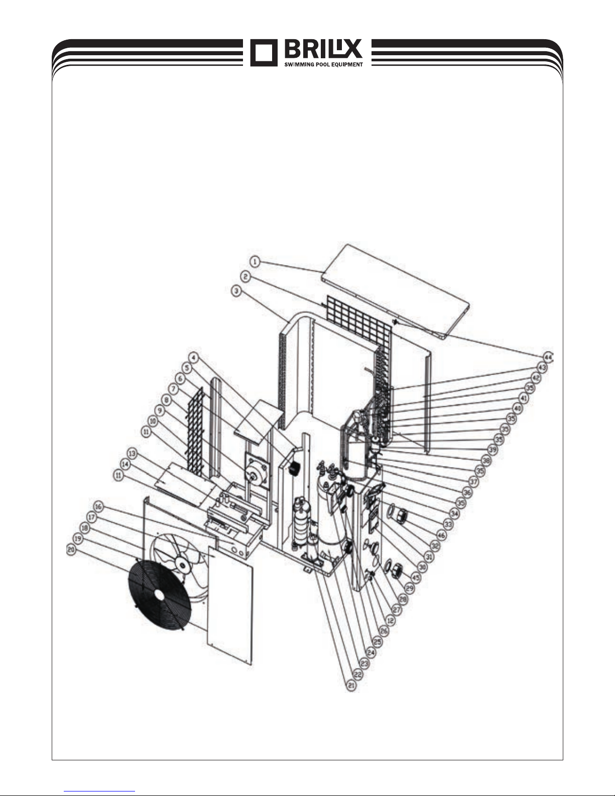
11. Exploded view

21
No. Part name No. Part name
1 Top cover 26 Wiring terminal
2 Rear grille 27 Intake valve
3 Vaporiser 28 Pressure gauge
4 Insulation plate 29 Blue sealing lip
5 PFC coil 30 Cover for wiring power supply
6 Pillar 31 Watertight box
7 Fan motor handle 32 Red sealing lip
8 Side grille 33 Regulator
9 Fan motor 34 Flow switch
10 Base 35 Copper pipes
11 Lead 36 High pressure switch
12 Drainage stopper 37 Low pressure switch 1
13 PC inverter board 38 Low pressure switch 2
14 Regulator box cover 39 Filter
16 Regulator box 40 Temperature sensor handle
17 Distribution board 41 4-way valve
18 Front panel 42 Rear panel
19 Fan blade 43 Electronic expansion valve
20 Fan grille 44 Ambient temperature sensor handle
21 Tank for liquid 45 Discharge water connection nut
22 Compressor 46 Water supply connection nut
23 Titanium exchanger
24 Terminal block
25 5-position electric terminal

 Loading...