

Page 1
Fixed
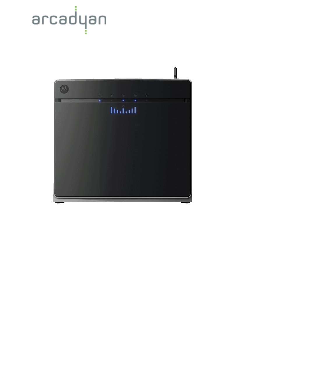
FXT-850W
MOTOROLA
Wireless Terminal
July 2010
MRV7517PW22-B1
FW R01
Page 2

Copyright Notice
Copyright of all the contents and materials published in the manual is owned
by Arcadyan. None of the materials provided on this manual may be
duplicated, reproduced or transmitted, either partially or completely, in any
form or by any means.
2010 Copyright Arcadyan Technology Corporation
Disclaimers
Arcadyan makes no warranty as to the materials and information in this
manual, including representations of the materials or information. The
materials or information are provided “as is”. There are no implied warranties
or conditions of merchantability, fitness for particular purpose or noninfringement. Arcadyan assumes no responsibility for the accuracy and
completeness of the information. Arcadyan may change the materials or
products mentioned therein at any time without notice. Arcadyan shall not be
liable for any special, indirect or consequential damages, including, without
limitation, damages resulting from use of or reliance on the information
presented, loss of profits or revenues or costs.
Submission of Information
Except as otherwise agreed by Arcadyan in writing, any material, information
or other communication you transmit or post to this manual will be deemed
non-confidential and non-proprietary (“Non-confidential Information”).
Arcadyan shall have no obligations with respect to the Non-confidential
Information. Arcadyan will be free to copy, disclose, distribute, incorporate
and otherwise use the Non-confidential Information and all data, images,
sounds, text, and other things embodied therein for any and all commercial or
non-commercial purposes.
Manufactured by Arcadyan Technology Corporation
4F No. 9 Park Avenue II,
Hsinchu Science Park
Hsinchu, Taiwan
Trademarks:
The Arcadyan brand name, logos, trademarks and service marks
(“Trademark”) used and displayed in this manual are registered and
unregistered trademark of Arcadyan. Arcadyan is not granting you a license
to use them in any way or function.
Other product and company names are trademarks or registered trademarks
of their respective holders.
Page 3

Table of Contents
CHAPTER 1 Introduction . . . . . . . . . . . . . . . . . . . . . . . . . . . . . . . . . . . . . . . . . . . . . . 1
About the Broadband Router. . . . . . . . . . . . . . . . . . . . . . . . . . . . . . .1
Features and Benefits . . . . . . . . . . . . . . . . . . . . . . . . . . . . . . . . . . . .2
Applications . . . . . . . . . . . . . . . . . . . . . . . . . . . . . . . . . . . . . . . . . . . .3
CHAPTER 2 Installation . . . . . . . . . . . . . . . . . . . . . . . . . . . . . . . . . . . . . . . . . . . . . . . 5
Hardware Installation. . . . . . . . . . . . . . . . . . . . . . . . . . . . . . . . . . . . .5
Package Contents . . . . . . . . . . . . . . . . . . . . . . . . . . . . . . . . . . . . . . . . . . 5
System Requirements . . . . . . . . . . . . . . . . . . . . . . . . . . . . . . . . . . . . . . . 6
Hardware Description . . . . . . . . . . . . . . . . . . . . . . . . . . . . . . . . . . . . . . . 7
ISP Settings. . . . . . . . . . . . . . . . . . . . . . . . . . . . . . . . . . . . . . . . . . . . . . 11
Connect the System . . . . . . . . . . . . . . . . . . . . . . . . . . . . . . . . . . . . . . . 11
Software Installation . . . . . . . . . . . . . . . . . . . . . . . . . . . . . . . . . . . .13
Configuring Client PC . . . . . . . . . . . . . . . . . . . . . . . . . . . . . . . . . . . . . . 13
Window XP . . . . . . . . . . . . . . . . . . . . . . . . . . . . . . . . . . . . . . . . . . . . . . 14
Window Vista . . . . . . . . . . . . . . . . . . . . . . . . . . . . . . . . . . . . . . . . . . . . . 14
Macintosh Computer . . . . . . . . . . . . . . . . . . . . . . . . . . . . . . . . . . . . . . . 17
CHAPTER 3 Web Management . . . . . . . . . . . . . . . . . . . . . . . . . . . . . . . . . . . . . . . 18
Navigating the Web Browser Interface . . . . . . . . . . . . . . . . . . . . . .19
Making Configuration Changes . . . . . . . . . . . . . . . . . . . . . . . . . . . .19
Start . . . . . . . . . . . . . . . . . . . . . . . . . . . . . . . . . . . . . . . . . . . . . . . . .20
Status. . . . . . . . . . . . . . . . . . . . . . . . . . . . . . . . . . . . . . . . . . . . . . . . . . . 20
WLAN . . . . . . . . . . . . . . . . . . . . . . . . . . . . . . . . . . . . . . . . . . . . . . . . . . 22
i
Page 4

Table of Contents
LAN . . . . . . . . . . . . . . . . . . . . . . . . . . . . . . . . . . . . . . . . . . . . . . . . . . . 32
Data. . . . . . . . . . . . . . . . . . . . . . . . . . . . . . . . . . . . . . . . . . . . . . . . .35
Firewall. . . . . . . . . . . . . . . . . . . . . . . . . . . . . . . . . . . . . . . . . . . . . . . . . 36
DNS & DDNS . . . . . . . . . . . . . . . . . . . . . . . . . . . . . . . . . . . . . . . . . . . . 51
NAT . . . . . . . . . . . . . . . . . . . . . . . . . . . . . . . . . . . . . . . . . . . . . . . . . . . 52
Wireless . . . . . . . . . . . . . . . . . . . . . . . . . . . . . . . . . . . . . . . . . . . . . . . . 58
Extras . . . . . . . . . . . . . . . . . . . . . . . . . . . . . . . . . . . . . . . . . . . . . . .61
HSPA Modem. . . . . . . . . . . . . . . . . . . . . . . . . . . . . . . . . . . . . . . . . . . . 62
Password Settings . . . . . . . . . . . . . . . . . . . . . . . . . . . . . . . . . . . . . . . 65
Time Settings . . . . . . . . . . . . . . . . . . . . . . . . . . . . . . . . . . . . . . . . . . . 66
Remote Management. . . . . . . . . . . . . . . . . . . . . . . . . . . . . . . . . . . . . . 67
Firmware Upgrade . . . . . . . . . . . . . . . . . . . . . . . . . . . . . . . . . . . . . . . 68
Diagnostic Utility. . . . . . . . . . . . . . . . . . . . . . . . . . . . . . . . . . . . . . . . . . 70
Reboot . . . . . . . . . . . . . . . . . . . . . . . . . . . . . . . . . . . . . . . . . . . . . . . . . 72
UPnP . . . . . . . . . . . . . . . . . . . . . . . . . . . . . . . . . . . . . . . . . . . . . . . . . . 73
Product Specifications. . . . . . . . . . . . . . . . . . . . . . . . . . . . . . . . . . . . . . . . . . . . . . 75
Compliance . . . . . . . . . . . . . . . . . . . . . . . . . . . . . . . . . . . . . . . . . . . . . . . . . . . . . . . 79
Federal Communication Commission Interference Statement. . . . . . . 79
ii
Page 5

CHAPTER 1 Introduction
Thank you for your purchase of the Fixed Wireless Terminal. We
are proud to provide you with a powerful yet simple communication
device for connecting your local area network (LAN) to the Internet. For
those who want to surf the Internet in the most secure way, this
Broadband Router provides a convenient and powerful solution. The
Broadband Router also enables service providers to provide their
residential and small office home office (SOHO) customers with 3G
mobile phone service as well as the high-quality VoIP service using
traditional analog telephones and fax machines.
About the Broadband Router
The Broadband Router provides Internet access to multiple users by
sharing a single-user account. It provides many secure and cost-effective
functions. It is simple to configure and can be up and running in
minutes. Support is provided for both wired and wireless devices. The
Broadband Router is compatible with 3GPP UMTS/HSPA+ and
compliant with IEEE 802.11n specification while maintaining full
backwards compatibility with the IEEE 802.11b/g standards. This
wireless networking standard utilizes advanced MIMO (multiple-in,
About the Broadband Router
1
Page 6

Introduction
multiple-out) technology to deliver incredible speed and range. With
wireless speeds up to 300Mbps - five times faster than 802.11g, the
Broadband Router provides sufficient bandwidth to listen to digital
music, play online games, transfer large files and surf the Internet
simultaneously. This device also provides wireless security via Wired
Equivalent Privacy (WEP), Wi-Fi Protected Access (WPA) and WPA2
encryption, and MAC address filtering.
Features and Benefits
• HSPA+ (High-Speed Packet Access) embedded for using mobile RAN
(Radio Access Network)
• WCDMA/HSPA as primary radio access and GSM/GPRS/EDGE as
fall-back
• Supports CSoHS (Circuit-Switched voice service over HSPA) air
interface of improving data and voice service system capacity.
• IEEE802.11n compliant
• Wireless speeds up to 300 Mbps
• Increased speed and coverage - up to 15 times the speed of IEEE
802.11g
• Fully backwards compatible with 802.11b/g wireless networks
• Allows you to stream HD video, listen to digital music, play online
games, transfer large files, make VoIP calls and surf the Internet
simultaneously
• Wi-Fi Multimedia (WMM) for wireless quality-of-service
• Local network connection via a 10/100 Mbps Ethernet port
• DHCP for dynamic IP configuration, and DNS for domain name
mapping
• Firewall with Stateful Packet Inspection, client privileges, intrusion
detection, and NAT
• NAT also enables multi-user Internet access via a single user
account, and virtual server functionality (providing protected access
to Internet services such as web, FTP, email, and Telnet)
Features and Benefits
2
Page 7

Introduction
• VPN transparent pass-through (IPSec-ESP Tunnel mode, L2TP,
PPTP)
• User-definable application sensing tunnel supports applications
requiring multiple connections
• Easy setup through a web browser on any operating system that
supports TCP/IP
• Compatible with all popular Internet applications
Applications
Many advanced networking features are provided by this Broadband
Router:
• Wired and Wireless LAN
The Broadband Router provides connectivity to 10/100 Mbps devices,
and wireless connection speed up to 300 Mbps. This router is fully
compliant with specifications defined in IEEE 802.11b, IEEE 802.11g
and IEEE 802.11n draft v2.0 standards, making it easy to create a
network in small offices or homes.
• Internet Access
This device UMTS (Universal Mobile Telecommunication System)
interface for your Internet connection.
• Shared IP Address
The Broadband Router provides Internet access for up to 253 users
via a single shared IP address. Using only one ISP account, multiple
users on your network can browse the web at the same time.
Applications
3
Page 8

Introduction
• Virtual Server
If you have a fixed IP address, you can set the Broadband Router to
act as a virtual host for network address translation. Remote users
access various services at your site using a constant IP address.
Then, depending on the requested service (or port number), the
Broadband Router can route the request to the appropriate server (at
another internal IP address). This secures your network from direct
attack by hackers, and provides more flexible management by
allowing you to change internal IP addresses without affecting
outside access to your network.
• DMZ Host Support
Allows a networked computer to be fully exposed to the Internet. This
function is used when NAT and firewall security prevent an Internet
application from functioning correctly.
• Security
The Broadband Router supports security features that deny Internet
access to specified users, or filter all requests for specific services that
the administrator does not want to serve. The Broadband Router’s
firewall also blocks common hacker attacks, including IP Spoofing,
Land Attack, Ping of Death, IP with zero length, Smurf Attack, UDP
port loopback, Snork Attack, TCP null scan, and TCP SYN flooding.
WPA/WPA2, IEEE802.1x, WEP, SSID, and MAC filtering provide
security over the wireless network.
Applications
4
Page 9

CHAPTER 2 Installation
123 4
Before installing the Broadband Router, verify that you have all the
items listed under “Package Contents.” If any of the items are missing
or damaged, contact your local distributor. Also be sure that you have all
the necessary cabling before installing the Broadband Router. After
installing the Broadband Router, refer to “Web Management” on
page 18 for detailed configuration.
Hardware Installation
Package Contents
Hardware Installation
5
Page 10

Installation
After unpacking the Broadband Router, check the contents of the box to
be sure you have received the following components:
1.Fixed Wireless Terminal
2. Power adapter
3. One CAT-5 Ethernet cable (RJ-45)
4. One documentation CD
Immediately inform your dealer in the event of any incorrect, missing,
or damaged parts. If possible, please retain the carton and original
packing materials in case there is a need to return the product.
System Requirements
To install and connect to the Broadband Router, you must have:
• 3G SIM card for UMTS (Univeral Mobile Telecommunication
System) connection.
• A computer with a CD-ROM drive.
• Windows 2000 or later, or Mac OS 9.x or later.
• An up to date web browser: Internet Explorer 5.5 or later, or
• Mozilla 1.7/Firefox 1.0 or later.
Hardware Installation
6
Page 11

Installation
Hardware Description
The Broadband Router connects to an Ethernet connection using it’s
RJ-45 LAN port. It can be connected directly to your PC or to a local
area network using the Fast Ethernet LAN ports.
The Broadband Router contains an integrated modem and connects to
the Internet or to a remote site using its RJ-11 port.
Data passing between devices connected to your local area network can
run at up to 100 Mbps over the Fast Ethernet port and up to 300 Mbps
over the built-in wireless access point.
The HSPA+ implementation of this Broadband Router offers 5.36 Mbps
in the uplink and 7.2 Mbps in the downlink.
The Broadband Router includes an LED display on the front panel for
system power and port indications that simplifies installation and
network troubleshooting.
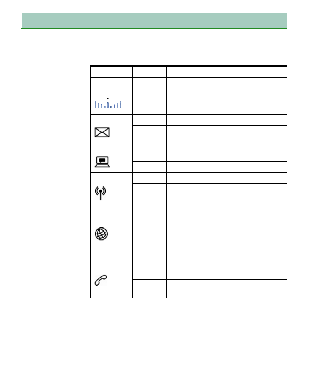
LED Indicators
The status LED indicators on the front panel are illustrated in the
following figure and table.
FIGURE 1. Front View
Hardware Installation
7
Page 12
Installation
The LED indicators on the top panel are illustrated by the following
table.
LED Status Description
Signal
Quality
Voice Mail Flashing Got voice mail message.
WAN Flashing The Broadband Router is establishing an
WLAN On Wireless LAN (WLAN) link.
Internet On Internet connection is functioning
On Shows the strength of the connection of
3G mobile network.
Flashing Browsing mobile network.
Off No message.
mobile network link.
Off No mobile network link.
Flashing The Broadband Router is sending or
receiving data via WLAN.
Off No WLAN link.
correctly.
Flashing The Broadband Router is establishing an
Internet link.
Off No Internet link.
Phone Line On Telephone line is off-hook, i.e., call in
progress.
Off Telephone line is on-hook. No call in
progress.
Hardware Installation
8
Page 13
Installation
Warning: Using the
wrong type of
power adapter may
cause damage.
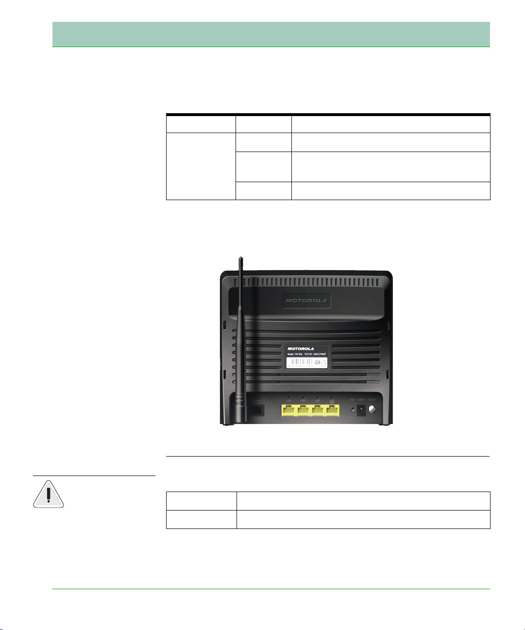
The LAN port LED indicators on the rear panel are illustrated by the
following table.
LED Status Description
LAN 1~4 On Ethernet link.
Flashing The LAN port is sending or receiving
data.
Off No Ethernet link.
Network Connectivity
The Broadband Router contains the following ports on the rear panel:
FIGURE 2. Rear View
The Broadband Router contains the following ports and buttons:
Item Description
Phone Port RJ-11 voice interface.
Hardware Installation
9
Page 14
Installation
Warning: Be sure
to insert the SIM
card into the card
socket before power
on the Broadband
Router.
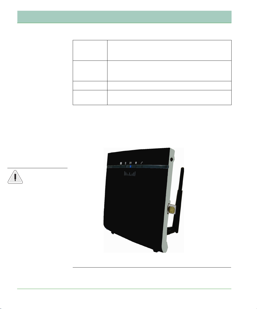
LAN Ports Fast Ethernet ports (RJ-45). Connect devices on your
local area network to these ports (i.e., a PC, hub,
switch or IP set top box).
Reset Button Use this button to reset the power and restore the
default factory settings. To reset without losing
configuration settings, see “Reboot” on page 72.
Power Inlet Connect the included power adapter to this inlet.
On/Off
Press this button to power on/off the device.
Button
SIM Card Slot
The embeded SIM card socket is located on the side panel as shown
below. It supports push-in/push-out mechanism. It is easy to insert and
to take out your SIM card by pressing the card into the slot.
FIGURE 3. Side View
Hardware Installation
10
Page 15

Installation
ISP Settings
Please collect the following information from your ISP before setting up
the Broadband Router:
• ISP account user name and password
• PIN code and UMTS account information
• Protocol, encapsulation and VPI/VCI circuit numbers
• DNS server address
• IP address, subnet mask and default gateway (for fixed IP users only)
Connect the System
The Broadband Router can be positioned at any convenient location in
your office or home. No special wiring or cooling requirements are
needed. You should, however, comply with the following guidelines:
• Keep the Broadband Router away from any heating devices.
• Do not place the Broadband Router in a dusty or wet environment.
• You should also remember to turn off the power, remove the power
cord from the outlet, and keep your hands dry when you install the
Broadband Router.
Hardware Installation
11
Page 16
Installation
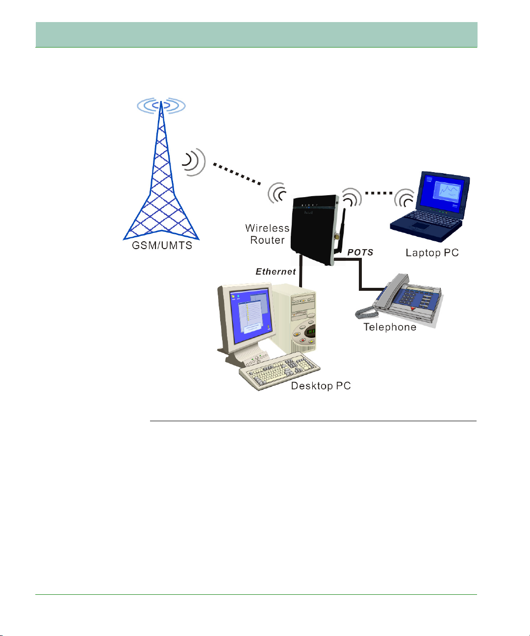
FIGURE 4. Application Diagram
Connect the Phone Line
Connect the phone line (RJ-11) cable from the port labelled Phone on the
Broadband Router to your telephone. When inserting the plug, be sure
the tab on the plug clicks into position to ensure that it is properly
seated.
Attach to Your Network Using Ethernet Cabling
The four LAN ports on the Broadband Router auto-negotiate the
connection speed to 10 Mbps or 100 Mbps, as well as the transmission
mode to half duplex or full duplex.
Hardware Installation
12
Page 17

Installation
Warning: Do not
plug a phone jack
connector into an
RJ-45 port. This
may damage the
Router.
Warning: keep your
hands dry when
you install the
Broadband Router.
Use RJ-45 cables to connect any of the four LAN ports on the Broadband
Router to an Ethernet adapter on your PC. Otherwise, cascade any of
the LAN ports on the Router to an Ethernet hub or switch, and then
connect your PC or other network equipment to the hub or switch. When
inserting an RJ-45 connector, be sure the tab on the connector clicks into
position to ensure that it is properly seated.
Use 100-ohm shielded or unshielded twisted-pair cable with RJ-45
connectors for all Ethernet ports. Category 5 cable is recommended.
Make sure each twisted-pair cable length does not exceed 100 meters
(328 feet).
Connect the Power Adapter
Plug the power adapter into the power socket on the rear of the
Broadband Router, and the other end into a power outlet.
In case of a power input failure, the Broadband Router will
automatically restart and begin to operate once the input power is
restored.
Software Installation
Configuring Client PC
After completing the hardware setup by connecting all your network
devices, you need to configure your computer to connect to the Router.
Depending on your operating system, see:
“Window XP” on page 14 ,
“Window Vista” on page 14
“Macintosh Computer” on page 17
Software Installation
13
Page 18
Installation
To access the Internet through the Router, you must configure the
network settings of the computers in your LAN to use the same IP
subnet as the Router. The default IP settings for the Router are:
IP address: 192.168.2.1
Subnet mask: 255.255.255.0
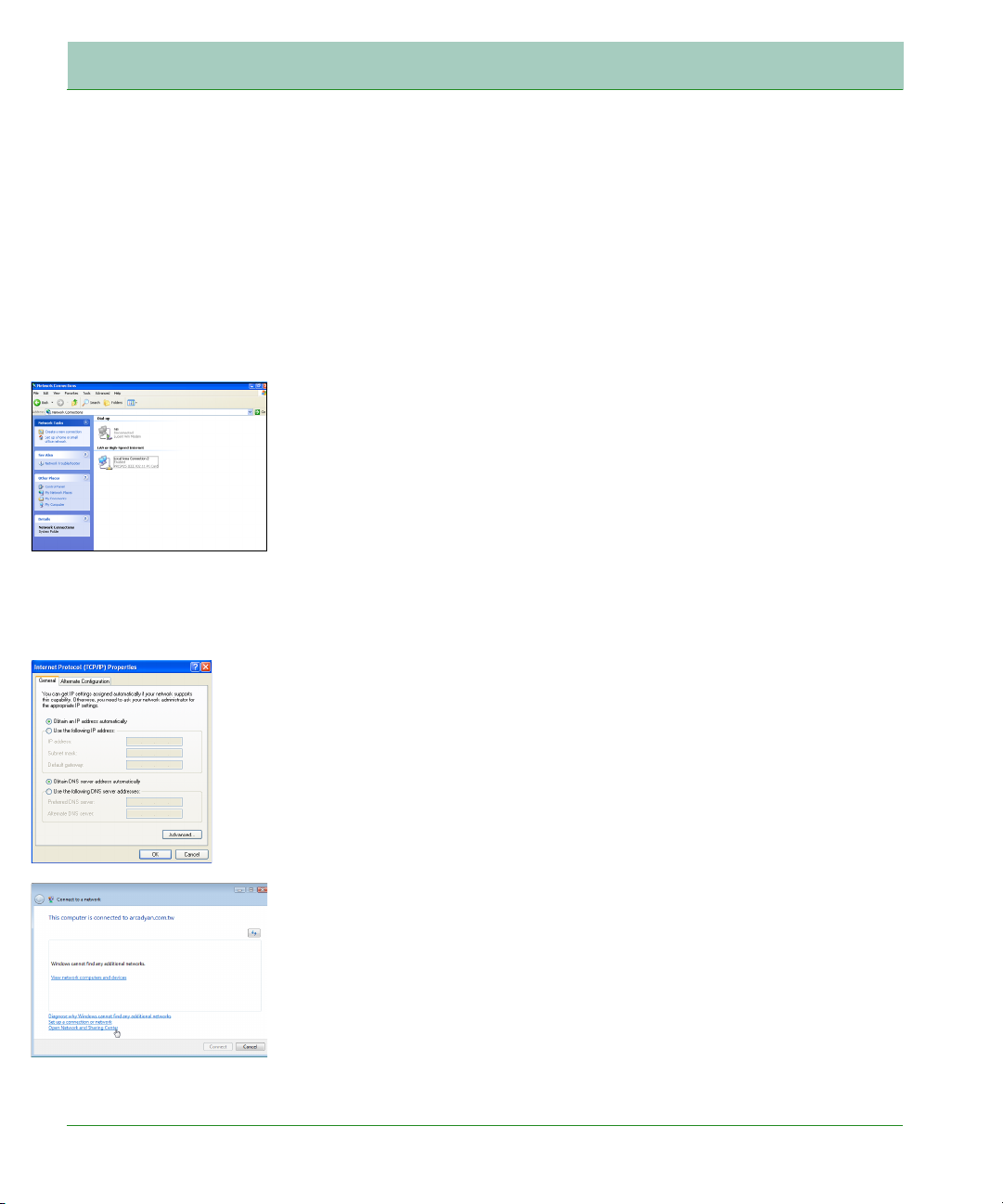
Window XP
1. On the Windows desktop, click Start/Control Panel.
2. In the Control Panel window, click Network and Internet
Connections.
3. The Network Connections window will open. Double-click the
connection for this device.
4. On the connection status screen, click Properties.
5. Double-click Internet Protocol (TCP/IP).
6. If Obtain an IP address automatically and Obtain DNS server
address automatically are already selected, your computer is already
configured for DHCP. If not, select this option.
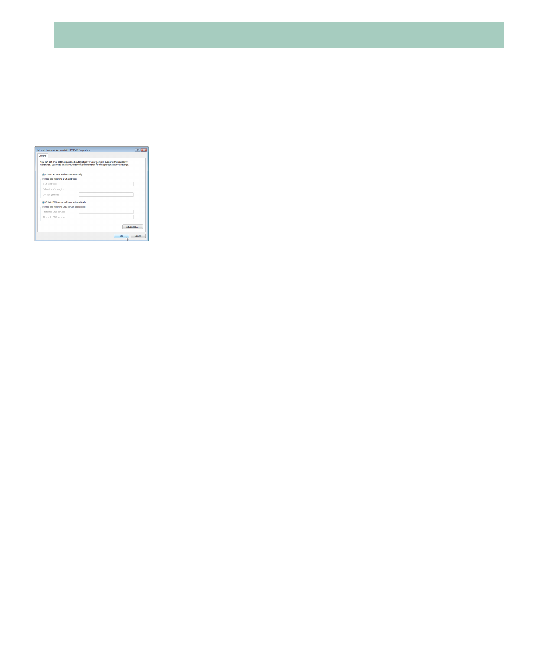
Window Vista
1. On the Windows desktop, click Start/Connet To.
2. The Connect to a network window will open. Click Open Network and
Sharing Center.
3. Click Manage network connections on the left menu bar of the screen.
Software Installation
14
Page 19
Installation
4. The LAN or High-Speed Internet window will open. Double-click the
connection for this device.
5. On the connection status screen, click Properties.
6. Double-click Internet Protocol (TCP/IP).
7. If Obtain an IPv6 address automatically and Obtain DNS server
address automatically are already selected, your computer is already
configured for DHCP. If not, select the options.
Obtain IP Settings From Your Wireless Broadband Router
Now that you have configured your computer to connect to your Router,
it needs to obtain new network settings. By releasing old DHCP IP
settings and renewing them with settings from your Router, you can
verify that you have configured your computer correctly.
1. On the Windows desktop, click Start/Programs/Accessories/
Command Prompt.
2. In the Command Prompt window, type ipconfig /release and press
the Enter key.
3. Type ipconfig /renew and press the Enter key. Verify that your IP
Address is now 192.168.2.xxx, your Subnet Mask is 255.255.255.0
and your Default Gateway is 192.168.2.1. These values confirm that
your Wireless Broadband Router is functioning correctly.
4. Type exit and press the Enter key to close the Command Prompt
window.
Your computer is now configured to connect to the Router.
Manual TCP/IP Settings
1. Follow steps 1-5 in “Window XP” on page 14.
2. Select Use the following IP Address.
3. Enter an IP address based on the default network 192.168.2.x (where
x is between 2 and 254), and use 255.255.255.0 for the subnet mask.
Use 192.168.2.1 for the Default gateway field.
Software Installation
15
Page 20

Installation
4. Select Use the following DNS server addresses.
5. Enter the IP address for the Wireless Broadband Router in the
Preferred DNS server field. This automatically relays DNS requests
to the DNS server(s) provided by your ISP. Otherwise, add a specific
DNS server into the Alternate DNS Server field and click OK to close
the dialog boxes.
Record the configured information in the following table.
TCP/IP Configuration Setting
IP Address____.____.____.____
Subnet Mask____.____.____.____
Preferred DNS Server____.____.____.____
Alternate DNS Server____.____.____.____
Default Gateway____.____.____.____
Software Installation
16
Page 21
Installation
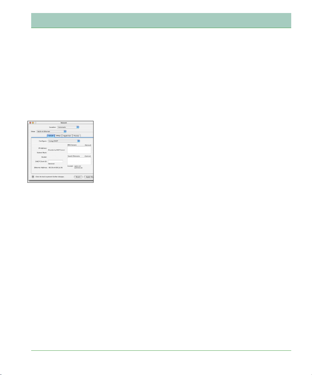
Macintosh Computer
You may find that the instructions here do not exactly match your
operating system. This is because these steps and screen shots were
created using Mac OS 10.2. Mac OS 7.x and above are similar, but may
not be identical to Mac OS 10.2.
Follow these instructions:
1. Pull down the Apple Menu . Click System Preferences.
2. Double-click the Network icon in the Systems Preferences window.
3. If Using DHCP Server is already selected in the Configure field, your
computer is already configured for DHCP. If not, select this option.
4. Your new settings are shown in the TCP/IP tab. Verify that your IP
Address is now 192.168.2.xxx, your Subnet Mask is 255.255.255.0
and your Default Gateway is 192.168.2.1. These values confirm that
your Wireless Broadband Router is functioning.
5. Close the Network window.
Now your computer is configured to connect to the Wireless Broadband
Router.
Disable HTTP Proxy
You need to verify that the “HTTP Proxy” feature of your web browser is
disabled. This is so that your browser can view the Router’s HTML
configuration pages. The following steps are for Internet Explorer.
Internet Explorer
1. Open Internet Explorer and click the Stop button. Click Explorer/
Preferences.
2. In the Internet Explorer Preferences window, under Network, select
Proxies.
3. Uncheck all check boxes and click OK.
Software Installation
17
Page 22
CHAPTER 3 Web Management
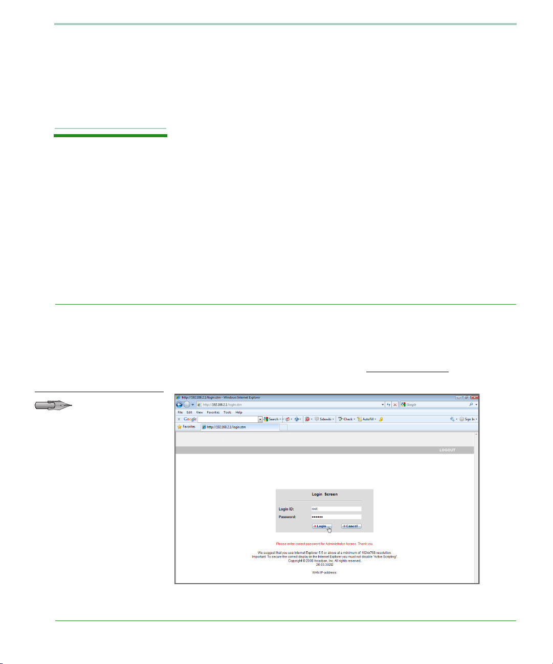
Note: The user
name is root and
the password is
123456 by default.
After you have configured TCP/IP on a client computer, you can
configure the Broadband Router using your web browser.
To access the Broadband Router’s management interface, enter the
default IP address in your web browser: http://192.168.2.1
user name and password, then click Login.
. Enter the
18
Page 23
Web Management
Navigating the Web Browser Interface
The Broadband Router’s management interface contains four main
sections:
• Start (on page 20)
• Data (on page 35)
• Extras (on page 61)
• Logout - click this to log out of the management interface.
Making Configuration Changes
Configurable parameters have a dialog box or a drop-down list. Once a
configuration change has been made on a screen, click the Apply or
Save Settings or Next button at the bottom of the screen to enable the
new setting.
To ensure proper screen refresh after a command entry, be sure that
Internet Explorer is configured as follows: Under the menu Tools/
Internet Options/General/Temporary Internet Files/Settings, the setting
for Check for newer versions of stored pages should be Every visit to the
page.
Navigating the Web Browser Interface
19
Page 24
Web Management
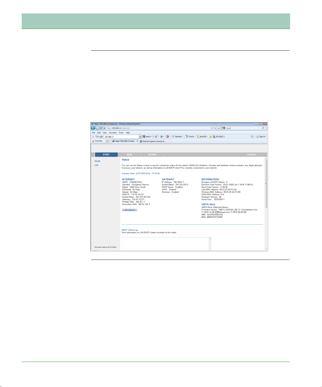
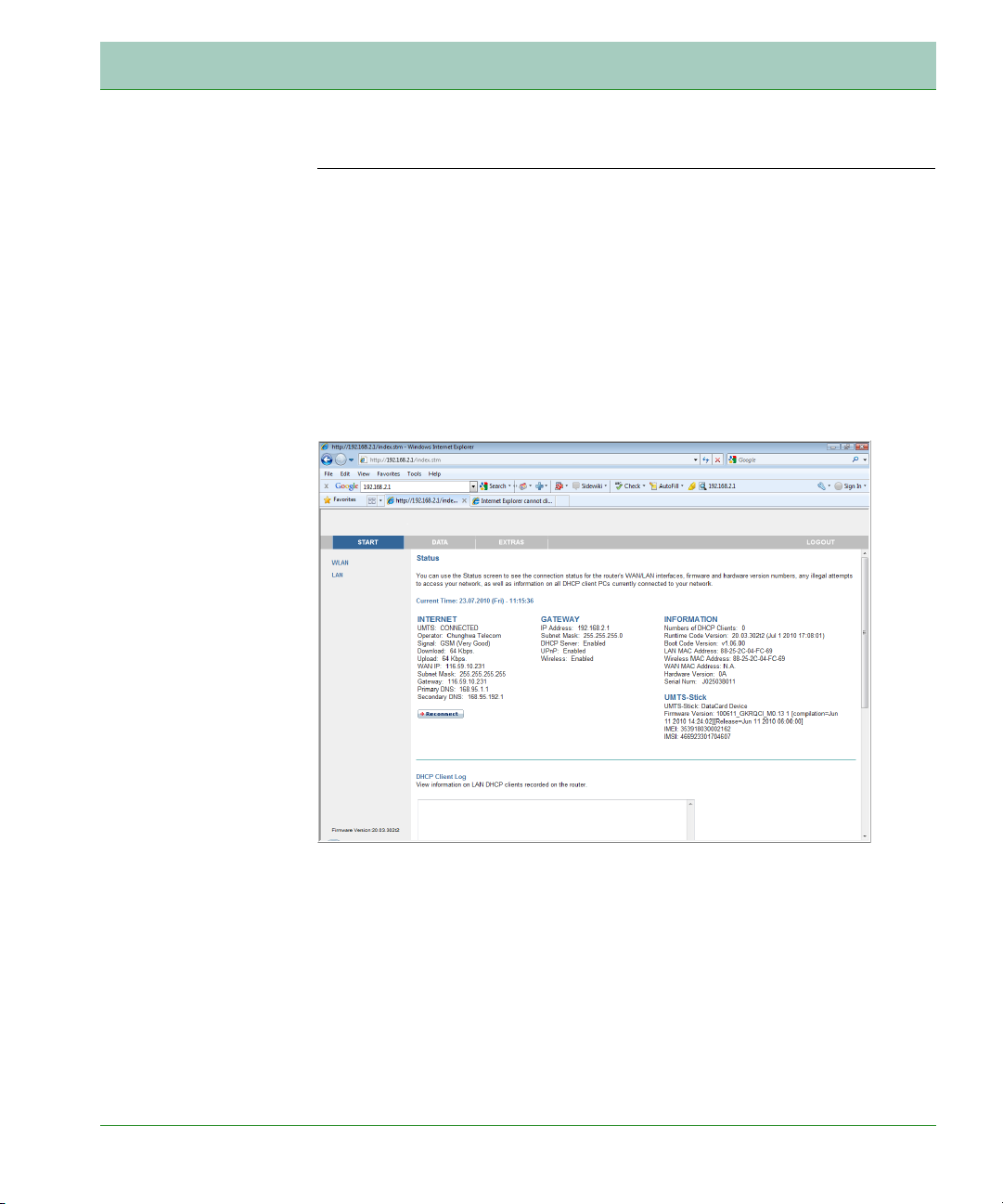
Start
On the left-hand side of the screen, the first menu item is Start. Click on
the Start menu, and the Status screen appears.
Status
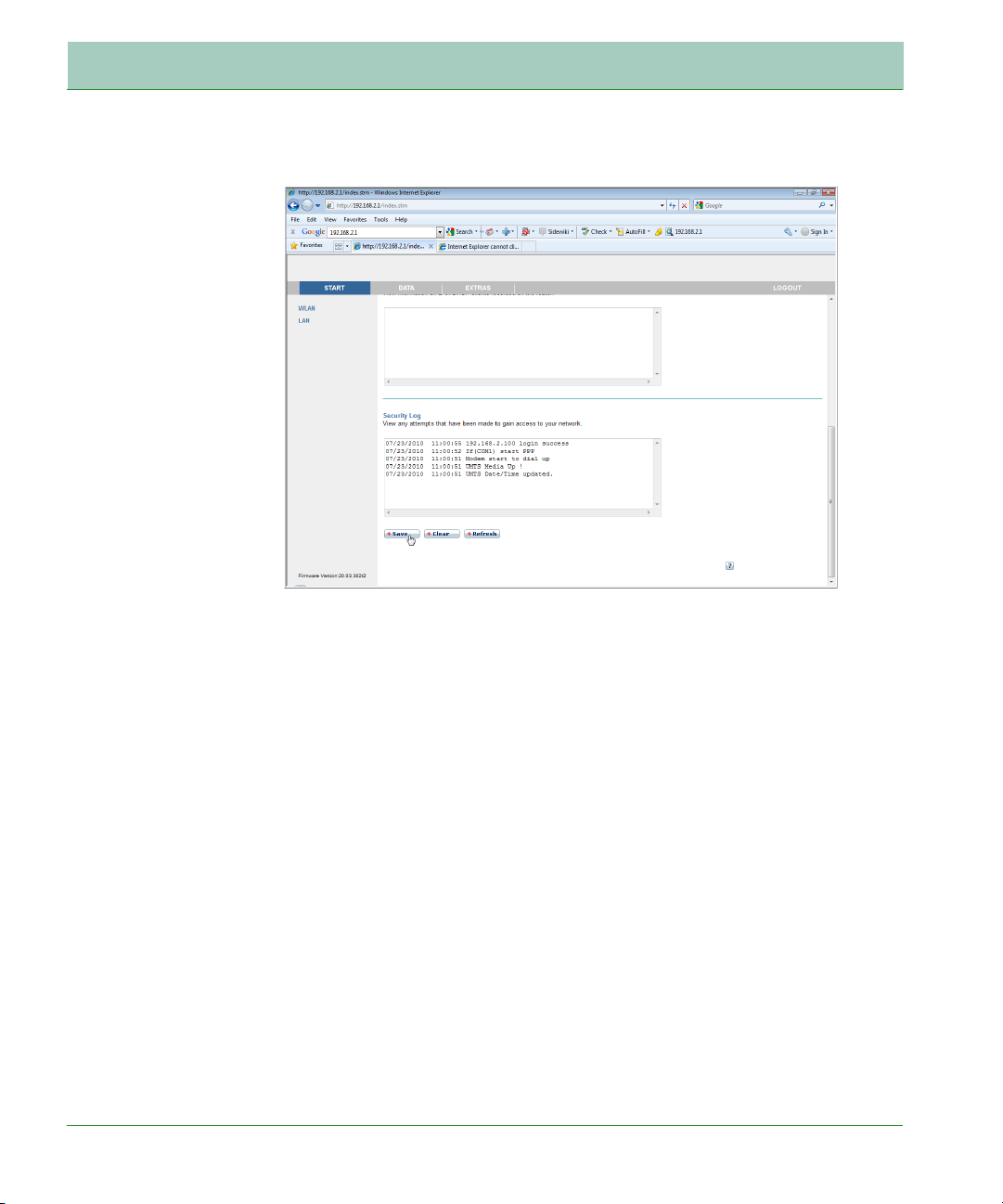
The Status screen displays WAN/LAN connection status, firmware and
hardware version numbers, illegal attempts to access your network, as
well as information on DHCP clients. The security log may be saved to a
file by clicking Save and choosing a location.
Start
20
Page 25
Web Management
Start21Start
Page 26

Web Management
WLAN
The Broadband Router operates as a wireless access point, allowing
wireless computers to communicate with each other. To configure this
function, you need to enable the wireless function, define the SSID and
the security options.
Parameter Description
SSID Specify a radio SSID (Service Set ID) to be used by
the Broadband Router and all of its wireless clients.
Note: Configure all of its clients to the same values.
Network
Security
• Pre-shared key type: Select the key type to
Passphrase or Hex.
• Pre-shared Key: Enter the key here.
22
Page 27

Web Management
Settings
Specify a common radio channel and SSID (Service Set ID) for the
Broadband Router, and all of its wireless clients. Be sure to configure
all of its clients to the same values.
Parameter Description
SSID
Broadcast
Wireless Mode This device supports 11n, 11g and 11b wireless
Bandwidth Set the bandwidth to 20 MHz, or 20/40 MHz.
Enable or disable the broadcasting of the SSID.
Disabling SSID broadcast will provide increased
security by hiding the SSID of your wireless network.
networks. Make your selection depending on the type
of wireless network that you have. We recommend
using “Mixed (11n+11g+11b) mode” to provide
compatibility with 11n, 11b and 11g wireless clients.
Start
23
Page 28

Web Management
Parameter Description
Channel The radio channel used by the wireless Router and
its clients to communicate with each other. This
channel must be the same on the Router and all of its
wireless clients. The Router will automatically assign
itself a radio channel, or you may select one
manually.
Extension
Channe
Protected
Mode
802.11e/WMM
QoS
Separated IP
Addresses for
LAN and
WLAN
Select the extension channel, if the bandwidth is set
to 20/40 MHz.
Enabling this function to ensure the best
performance of your 11n throughput in case there is
a lot of interference from the 11g and 11b devices in
the wireless network.
Enable or disable the use of QoS. The QoS (Quality of
Service) function allows you to differentiate WMM
(Wi-Fi Multimedia) traffic and provide it with highpriority forwarding service
Enabling this function for automatically separating
the IP addresses for LAN and WLAN connections.
Start
24
Page 29

Web Management
Note: Selecting the
Disabled option
will turn off the
wireless security
function. We suggest that you turn
on the security
function to protect
your wireless communication.
Security
To make your wireless network safe, you should turn on the security
function. The Broadband Router supports WEP (Wired Equivalent
Privacy), WPA (Wi-Fi Protected Access) and WPA2 security
mechanisms. This Router also supports WPS (Wi-Fi Protected Setup).
Enable WPS Function: check this box to enable WPS. Enter the PIN in
the WPS-PIN field, and click Start to establish WPS.
WPS-PIN for External Registrar: click Generate to create a new PIN.
Or you can click Default to restore the default PIN. Take this PIN you
see on the screen, and enter it on the client side.
The following security options are available:
• WPA/WPA2
• WPA2 Only
• WPA Only
• WEP
• Disabled
Start
25
Page 30

Web Management
Authentication: this is the authentication method used by clients.
If the Allowed Client Type is set to WPA/WPA2 or WPA2 Only or
WPA Only, then you should set the authentication to 802.1X or PSK.
WPA/WPA2, WPA2 Only, WPA Only (PSK)
Wi-Fi Protected Access (WPA) combines temporal key integrity protocol
(TKIP) and 802.1X mechanisms. It provides dynamic key encryption
and 802.1X authentication service.
Wi-Fi Protected Access 2 (WPA2) is a product certification that is
available through the Wi-Fi Alliance. WPA2 certifies that wireless
equipment is compatible with the IEEE 802.11i standard. The WPA2
product certification formally replaces Wired Equivalent Privacy (WEP)
and the other security features of the original IEEE 802.11 standard.
The goal of WPA2 certification is to support the additional mandatory
security features of the IEEE 802.11i standard that are not already
included for products that support WPA.
Parameter Description
Authentication
Choose 802.1X or Pre-shared Key to use as the
authentication method.
802.1X: for the enterprise network with a RADIUS
server.
Pre-shared key (PSK): for the SOHO network
environment without an authentication server.
Start
26
Page 31

Web Management
WPA/WPA2, WPA2 Only, WPA Only with 802.1X
If 802.1X is used in your network, you can configure the settings in this
screen.
Parameter Description
Authentication
Session Idle
timeout
ReAuthentication
Period
Quiet Period Defines a maximum period of time for which the
Server IP The IP address of your authentication server.
Server Port The port used for the authentication service.
Choose 802.1X authentication option.
Defines a maximum period of time for which the
connection is maintained during inactivity.
Defines a maximum period of time for which the
authentication server will dynamically re-assign a
session key to a connected client.
Router will wait between failed authentications.
Start
27
Page 32

Web Management
Parameter Description
Secret Key The secret key shared between the authentication
server and its clients.
NAS-ID Defines the request identifier of the Network Access
Server.
WEP-Dynamic
If you want to use WEP to protect your wireless network, you need to set
the same parameters for the Router and all your wireless clients.
Parameter Description
WEP Mode Select 64-bit or 128-bit key to use for encryption.
Key
Provisioning
Select Dynamic to enable 802.1X function.
Start
28
Page 33

Web Management
Parameter Description
Session Idle
timeout
ReAuthentication
Period
Quiet Period Defines a maximum period of time for which the
Server IP The IP address of your authentication server.
Server Port The port used for the authentication service.
Secret Key The secret key shared between the authentication
NAS-ID Defines the request identifier of the Network Access
Defines a maximum period of time for which the
connection is maintained during inactivity.
Defines a maximum period of time for which the
authentication server will dynamically re-assign a
session key to a connected client.
Router will wait between failed authentications.
server and its clients.
Server.
Start
29
Page 34

Web Management
WEP-Static
Parameter Description
WEP Mode Select 64-bit or 128-bit key to use for encryption.
Key
Provisioning
Select Static if there is only one fixed key for
encryption.
Start
30
Page 35

Web Management
Timer
You can also control the wireless function of the Broadband Router
based on a time schedule.
Check the day of the week, and enter the start/end time, and click on
Add/Configure icon to set the schedule.
For the existing entry, you can edit the parameters, or delete that entry.
During the above times the wireless function will be:
• If you set this to activated, the wireless function will be on in the
configured time schedule.
• If you select deactivated, the wireless function will then be off in
that configured time period.
Start
31
Page 36

Web Management
LAN
The LAN settings screen allows you to change the default IP address of
the Router and modify the DHCP server settings.
Start
32
Page 37

Web Management
Parameter Description
LAN IP:
IP Address The IP address of the Router.
IP Subnet
Mask
Host Name Enter the name of the Router.
DHCP
Server
The subnet mask of the Router.
Check this option to enable the DHCP server
function on this Router.
Start
33
Page 38

Web Management
Parameter Description
DHCP Server Parameters:
Address Pool
Start IP
Address Pool
End IP
Lease Time Allows you to select a pre-defined lease time for IP
Domain
Name
Static DHCP You can assign a static IP to a certain MAC address
Specify the start IP address of the DHCP pool. Do not
include the gateway address of the Router in the
client address pool. If you change the pool range,
make sure the first three octets match the gateway’s
IP address, i.e., 192.168.2.xxx.
Specify the end IP address of the DHCP pool.
addresses assigned using DHCP. For home networks
this may be set to Forever, which means there is no
time limit on the IP address lease.
If your network uses a domain name, enter it here.
Otherwise, leave this field blank.
within your network. You can enter up to 10 entries
here in this table.
Start
34
Page 39

Web Management
Data
The Advanced configuration section, on the left-hand side displays the
main menu and the right-hand side shows descriptive information.
The Data section contains the following menu items as described in the
following table.
Parameter Description
WAN Specifies the Internet connection settings.
Firewall Configures a variety of security and specialized
functions including: Access Control, URL blocking,
Internet access control scheduling, intruder detection
and DMZ.
SNMP Community string and trap server settings.
DNS & DDNS Configures the DNS and DDNS function.
Data
35
Page 40

Web Management
Note: The firewall
does not significantly affect system performance,
so we advise
enabling the prevention features to
protect your network.
Parameter Description
NAT Configures address mapping, virtual server and
special applications.
Wireless Configures the radio frequency, SSID, and security
for wireless communications.
Firewall
The firewall inspects packets at the application layer, maintains TCP
and UDP session information including time-outs and the number of
active sessions, and provides the ability to detect and prevent certain
types of network attacks. Network attacks that deny access to a network
device are called Denial-of-Service (DoS) attacks. DoS attacks are aimed
at devices and networks with a connection to the Internet. Their goal is
not to steal information, but to disable a device or network so users no
longer have access to network resources.
It also protects against the following DoS attacks: IP Spoofing, Land
Attack, Ping of Death, IP with zero length, Smurf Attack, UDP port
loopback, Snork Attack, TCP null scan and TCP SYN flooding.
Data
36
Page 41

Web Management
The firewall function is enabled by default. This feature does not
significantly affect system performance, so we advise leaving this
function enabled to protect your network.
Access Control
The following items are displayed on the Access Control screen.
Parameter Description
Enable
Filtering
Function
Normal
Filtering Table
Click Add PC on the Access Control screen to view the following screen.
Data
Enables or disables the filtering function.
Displays the IP address (or an IP address range)
filtering table.
37
Page 42

Web Management
Access Control/Add PC
To create a new access control rule:
1. Click Add PC on the Access Control screen. The Access Control Add
PC screen will appear.
2. Define the appropriate settings for client PC services.
3. Click OK and then click SAVE SETTINGS to save your settings.
Data
38
Page 43

Web Management
MAC Filter
The MAC Filter allows you to define what client PC’s can access the
Internet. When enabled only the MAC addresses defined in the MAC
Filtering table will have access to the Internet. All other client devices
will be denied access.
You can enter up to 32 MAC addresses in this table.
Data
39
Page 44

Web Management
URL Blocking
The VoIP Router allows the user to block access to web sites from a
particular PC by entering either a full URL address or just a keyword.
This feature can be used to protect children from accessing violent or
pornographic web sites.
To configure the URL Blocking feature, use the table below to specify
the web sites (www.somesite.com) and/or keywords you want to filter on
your network.
To complete this configuration, you will need to create or modify an
access rule in “Access Control” on page 37. From the Access Control,
Add PC section, check the option for WWW with URL Blocking in the
Client PC Service table to filter out the web sites and keywords selected.
You can define up to 30 sites here.
Data
40
Page 45

Web Management
Schedule Rule
You may filter Internet access for local clients based on rules.
Each access control rule may be activated at a scheduled time. Define
the schedule on the Schedule Rule screen, and apply the rule on the
Access Control screen.
Data
41
Page 46

Web Management
Edit Schedule Rule
You can create and edit schedule rules on this screen.
1. Click Add Schedule Rule icon on the Schedule Rule screen. The
Edit Schedule Rule screen will appear.
2. Define the appropriate settings for a schedule rule.
3. Click Apply to save your settings.
Data
42
Page 47

Web Management
Intrusion Detection
The Broadband Router’s firewall inspects packets at the application
layer, maintains TCP and UDP session information including timeouts
and number of active sessions, and provides the ability to detect and
prevent certain types of network attacks such as Denial-of-Service (DoS)
attacks.
Data
43
Page 48

Web Management
Network attacks that deny access to a network device are called DoS
attacks. DoS attacks are aimed at devices and networks with a
connection to the Internet. Their goal is not to steal information, but to
disable a device or network so users no longer have access to network
resources.
The Broadband Router protects against DoS attacks including: Ping of
Death (Ping flood) attack, SYN flood attack, IP fragment attack
(Teardrop Attack), Brute-force attack, Land Attack, IP Spoofing attack,
Data
44
Page 49

Web Management
IP with zero length, TCP null scan (Port Scan Attack), UDP port
loopback, Snork Attack.
Parameter Defaults Description
Enable SPI and
Anti-DoS
firewall
protection
Yes The Intrusion Detection feature of the
Router limits the access of incoming
traffic at the WAN port. When the
Stateful Packet Inspection (SPI) feature
is turned on, all incoming packets are
blocked except those types marked with a
check in the Stateful Packet Inspection
section at the top of the screen.
Data
45
Page 50

Web Management
Parameter Defaults Description
Stateful Packet
Inspection
This option allows you to select different
application types that are using dynamic
port numbers. If you wish to use Stateful
Packet Inspection (SPI) for blocking
packets, click on the Yes radio button in the
“Enable SPI and Anti-DoS firewall
protection” field and then check the
inspection type that you need, such as
Packet Fragmentation, TCP Connection,
UDP Session, FTP Service, H.323 Service,
and TFTP Service.
It is called a “stateful” packet inspection
because it examines the contents of the
packet to determine the state of the
communication; i.e., it ensures that the
stated destination computer has previously
requested the current communication. This
is a way of ensuring that all
communications are initiated by the
recipient computer and are taking place
only with sources that are known and
trusted from previous interactions. In
addition to being more rigorous in their
inspection of packets, stateful inspection
firewalls also close off ports until a
connection to the specific port is requested.
When particular types of traffic are
checked, only the particular type of traffic
initiated from the internal LAN will be
allowed. For example, if the user only
checks FTP Service in the Stateful Packet
Inspection section, all incoming traffic will
be blocked except for FTP connections
initiated from the local LAN.
Data
46
Page 51

Web Management
Parameter Defaults Description
Hacker Prevention Feature
Discard Ping
from WAN
RIP Defect Enabled If the router does not reply to an IPX RIP
When hackers attempt to enter your network, we can alert you by
email
Your E-mail
Address
SMTP Server
Address
POP3 Server
Address
User Name Enter your email account user name.
Discard Prevents a ping on the Router’s WAN
port from being routed to the network.
request packet, it will stay in the input
queue and not be released. Accumulated
packets could cause the input queue to
fill, causing severe problems for all
protocols. Enabling this feature prevents
the packets accumulating.
Enter your email address.
Enter your SMTP server address (usually
the part of the email address following
the “@” sign).
Enter your POP3 server address (usually
the part of the email address following
the “@” sign).
Password Enter your email account password.
Connection Policy
Fragmentation
half-open wait
10 secs Configures the number of seconds that a
packet state structure remains active.
When the timeout value expires, the
router drops the unassembled packet,
freeing that structure for use by another
packet.
Data
47
Page 52

Web Management
Parameter Defaults Description
TCP SYN wait 30 secs Defines how long the software will wait
for a TCP session to reach an established
state before dropping the session.
TCP FIN wait 5 secs Specifies how long a TCP session will be
managed after the firewall detects a FINexchange.
TCP connection
idle timeout
UDP session
idle timeout
H.323 data
channel idle
timeout
DoS Detect Criteria
Total incomplete
TCP/UDP
sessions HIGH
Total incomplete
TCP/UDP
sessions LOW
Incomplete TCP/
UDP sessions
(per min.) HIGH
3600 secs
(1 hour)
30 secs The length of time for which a UDP
180 secs The length of time for which an H.323
300
sessions
250
sessions
250
sessions
The length of time for which a TCP
session will be managed if there is no
activity.
session will be managed if there is no
activity.
session will be managed if there is no
activity.
Defines the rate of new unestablished
sessions that will cause the software to
start deleting half-open sessions.
Defines the rate of new unestablished
sessions that will cause the software to
stop deleting half-open sessions.
Maximum number of allowed incomplete
TCP/UDP sessions per minute.
Incomplete TCP/
UDP sessions
(per min.) LOW
Data
200
sessions
Minimum number of allowed incomplete
TCP/UDP sessions per minute.
48
Page 53

Web Management
Parameter Defaults Description
Maximum
incomplete TCP/
UDP sessions
number from
same host
Incomplete TCP/
UDP sessions
detect sensitive
time period
Maximum halfopen
fragmentation
packet number
from same host
Half-open
fragmentation
detect sensitive
time period
Flooding cracker
block time
30 Maximum number of incomplete TCP/
UDP sessions from the same host.
900
msecs
20 Maximum number of half-open
10000
msecs
300 secs Length of time from detecting a flood
Length of time before an incomplete TCP/
UDP session is detected as incomplete.
fragmentation packets from the same
host.
Length of time before a half-open
fragmentation session is detected as halfopen.
attack to blocking the attack.
Data
49
Page 54

Web Management
DMZ
If you have a client PC that cannot run an Internet application properly
from behind the firewall, you can open the client up to unrestricted twoway Internet access. Enter the IP address of a DMZ (Demilitarized
Zone) host on this screen. Adding a client to the DMZ may expose your
local network to a variety of security risks, so only use this option as a
last resort.
Data
50
Page 55

Web Management
DNS & DDNS
DNS
A Domain Name Server (DNS) is an index of IP addresses and web site
addresses. If you type a web site address into your browser, such as
www.abc.de, a DNS server will find that name in its index and find the
matching IP address: 111.222.333.444. Most ISP’s provide a DNS server
for speed and convenience. Since your ISP may connect to the Internet
with dynamic IP settings, it is likely that the DNS server IP’s are also
provided dynamically. However, if there is a DNS server that you would
rather use, you need to specify the IP address here.
DDNS
Dynamic Domain Name Service (DDNS) provides users on the Internet
with a method to tie their domain name to a computer or server. DDNS
allows your domain name to follow your IP address automatically by
having your DNS records changed when your IP address changes.
This DNS feature is powered by DynDNS.org or TZO.com. With a DDNS
connection you can host your own web site, email server, FTP site, and
more at your own location even if you have a dynamic IP address.
Data
51
Page 56

Web Management
NAT
Network Address Translation allows multiple users to access the
Internet sharing one public IP.
• Enable NAT function : click on the checkbox to enable this function.
Data
52
Page 57

Web Management
Address Mapping
Address mapping allows one or more public IP addresses to be shared by
multiple internal users. This also hides the internal network for
increased privacy and security.
Enter a range of internal IPs that will share the global IP, and then
enter the Public IP address you wish to share into the global IP field.
Data
53
Page 58

Web Management
Port Mapping
You can configure the Router as a virtual server so that remote users
accessing services such as the web or FTP at your local site via public IP
addresses can be automatically redirected to local servers configured
with private IP addresses. In other words, depending on the requested
service (TCP/UDP port number), the Router redirects the external
service request to the appropriate server (located at another internal IP
address). This tool can support both port ranges, multiple ports and
combinations of the two. For example:
• Port Ranges: e.g. 100-150
• Multiple Ports: e.g. 25,110,80
• Combination: e.g. 25-100,80
Click Configure/add icon to add a new entry.
Data
54
Page 59

Web Management
Data55Data
Page 60

Web Management
Special Applications
Some applications, such as Internet gaming, videoconferencing, Internet
telephony and others, require multiple connections. These applications
cannot work with Network Address Translation (NAT) enabled. If you
need to run applications that require multiple connections, use the
following screen to specify the additional public ports to be opened for
each application.
Specify the public port number normally associated with an application
in the Trigger Port field. Set the protocol type to TCP or UDP, then
enter the ports that the application requires.
Popular applications requiring multiple ports are listed in the Popular
applications field. From the drop-down list, choose the application and
then choose a row number to copy this data into.
56
Page 61

Web Management
NAT Mapping Table
NAT Mapping Table displays the current NAPT (Network Address Port
Translation) address mappings. As the NAT mapping is dynamic, a
Refresh button is provided to refresh the NAT Mapping Table with the
most up-to-date values.
The content of the NAT Mapping Table is described as follows:
• Protocol - protocol of the flow.
• Local IP - local (LAN) host’s IP address for the flow.
• Local Port - local (LAN) host’s port number for the flow.
• Pseudo IP - translated IP address for the flow.
• Pseudo Port - translated port number for the flow.
• Peer IP - remote (WAN) host’s IP address for the flow.
• Peer Port - remote (WAN) host’s port number for the flow.
Data
57
Page 62

Web Management
Note: There is a
WLAN button
located on the
device, you can set
to activate or deactivate this button.
Wireless
WLAN
The Router also operates as a wireless access point, allowing wireless
computers to communicate with each other. To configure this function,
all you need to do is enable the wireless function, define the SSID, and
the security options.
• WLAN Function: select to enable or to disable the wireless function,
or you can use this function based on a time schedule.
• SSID: Service Set ID, this is the name of your wireless network.
Specify the SSID to be used by the Router and all of its wireless
clients. Be sure you configure all of its clients to the same values.
• Network Security: if WPA/WPA2 and PSK is used as your wireless
security method, select Passphrase or HEX to use as your key entry
method. Refer to “Security” on page 25 for more details.
Data
58
Page 63

Web Management
Access Control
Using the Access Control functionality, you can restrict access based on
MAC address. Each PC has an unique identifier known as a Medium
Access Control (MAC) address. With MAC filtering enabled, the
computers whose MAC address you have listed in the filtering table will
be able to connect (or will be denied access) to the Broadband Router.
• Enable MAC Filtering: select to enable or disable this function.
• Access Rule for registered MAC address: select to allow/deny access
for the registered MAC addresses. Selecting Allow means only MAC
addresses registered here will be able to connect to the Broadband
Router.
Data
59
Page 64

Web Management
• Selecting Deny means only the MAC addresses registered here will
be denied access to the Broadband Router.
• MAC Filtering Table: you can enter up to 32 addresses here in the
table. Click Enter for the Add currently associated MAC stations
option to quickly copy the entry to the MAC Filtering table.
WDS
The Wireless Distribution System (WDS) provides means to extend the
range of a Wireless Local Area Network (WLAN). WDS allows an Access
Point (AP) to establish a direct link to other APs and to allow stations to
roam freely within the area covered by the WDS.
• Enable WDS function: check this box to enable this function.
• Rescan: click this button to refresh the list of available access points.
Available access points will show up on the AP MAC Address Table,
check the box to add that particular access point to the WDS.
Data
60
Page 65

Web Management
Extras
The Broadband Router supports the following extra functions described
in the table below:
Menu Description
HSPA Modem The high-speed packet access (HSPA) delivers
5.8 Mbps of the uplink and 14 Mpbs in the downlink.
Password
Settings
Time Settings Sets the local time zone, etc.
Remote
Management
Firmware
Upgrade
Diagnostic
Utility
Reboot Performs system reboot if the Router stops
UPnP Enables/disables the Universal Plug and Play
Sets the password for administrator access.
Enables/disables remote management of the Router.
Allows you to upgrade your firmware version.
Allows you to test network connection status.
responding.
function.
Extras
61
Page 66

Web Management
HSPA Modem
UMTS-Stick
Universal Mobile Telecommunications System (UMTS) is one of the
third-generation (3G) mobile telecommunications technologies. It
combines three different air interfaces, GSM’s Mobile Application Part
(MAP) core, and the GSM family of speech codecs.
The Broadband Router enables a connection with a UMTS-Stick for
Internet and Voice over the UMTS mobile network. Please insert the
SIM card into the UMTS jack of the Router. Then, enter the PIN code of
the SIM card on the screen.
Enter the PIN code of your SIM card on the screen. Check the Store
PIN box to store the PIN. Thus, this Router will remember the PIN
code.
Extras
62
Page 67

Web Management
Click on Change PIN Code if required by your ISP. The following
screen will appear. Click Apply to save your setting.
See the following table for additional parameters that needs to be
configured.
Parameter Description
Backup
connection
This sets how the UMTS connection is used
primarily.
APN Access Point Name, this is the name used to identify
a general packet radio service (GPRS) bearer service
in the GSM mobile network. The APN defines the
type of service that is provided in the packet data
connection. This information should be provided by
your ISP.
Phone Number This is the number to dial to connect to your ISP.
This information should be provided by your ISP.
Extras
63
Page 68

Web Management
Parameter Description
Idle Time
(Minutes)
User Name/
Password
Confirm
Password
The service information is displayed in the Network Operator section
on the screen. Click Rescan/Refresh to update the information.
This is the time period in which there is no Internet
connection activity before the mobile connection goes
to automatic termination.
Enter user name and password.
Enter your password again.
Select your telecommunications service and click Apply for the HSPA
connection.
Extras
64
Page 69

Web Management
Note: If you lost the
password, or you
cannot gain access
to the user interface, press the reset
button on the rear
panel, holding it
down for at least 10
seconds to restore
the factory
defaults. The
default user name
is root, and password is 123456.
Password Settings
Use this screen to change the password for accessing the management
interface. Passwords can contain from 3~12 alphanumeric characters
and are case sensitive.
Enter a maximum Idle Time Out (in minutes) to define a maximum
period of time for which the login session is maintained during
inactivity. If the connection is inactive for longer than the maximum idle
time, it will perform system logout, and you have to log in again to
access the management interface. (Default: 10 minutes)
Extras
65
Page 70

Web Management
Time Settings
Select your local time zone from the drop down list. This information is
used for log entries and client filtering.
For accurate timing of log entries and system events, you need to set the
time zone. Select your time zone from the drop down list.
If you want to automatically synchronize the Broadband Router with a
public time server, check the Enable Automatic Time Server
Maintenance box.
Click Apply.
Extras
66
Page 71

Web Management
Note: If you check
Enabled and specify an IP address of
0.0.0.0, any remote
host can manage
the Broadband
Router.
Remote Management
By default, management access is only available to users on your local
area network. However, you can also manage the Broadband Router
from a remote host by entering the IP address of a remote computer on
this screen.
Check the Enabled box, and enter the IP address of the Host Address
and Port Number, then click Apply.
For remote management via WAN IP address you need to connect using
port 8080. Simply enter WAN IP address followed by: 8080, for example,
211.20.16.1:8080.
Extras
67
Page 72

Web Management
Firmware Upgrade
Extras
68
Page 73

Web Management
Note: Be sure to
remove the mobile
SIM card from the
slot before click on
the Restore button.
• Firmware Upgrade: this allows you to upgrade to the latest
firmware.
To update the firmware:
1. Download the upgrade file from company web site, and save it to your
hard drive.
2. Then click Browse... to look for the downloaded file. Click Apply to
begin the upgrade.
• HSPA Modem Firmware Upgrade:
To update the HSPA firmware:
1. Remove the SIM card from the jack slot.
2. Download the upgrade file from company web site, and save it to your
hard drive.
3. Then click Browse... to look for the downloaded file. Click Apply to
begin the upgrade.
• Check the Status screen Information section to confirm that the
upgrade process was successful.
• Backup Configuration of Broadband Router: this allows you to save
the system configuration to a file. To backup the configuration file,
just click the Backup button on the screen.
• Restore Configuration of Broadband Router: this function is used to
restore the previously saved backup configuration file. To restore the
configuration file: click Browse... to locate the previously saved file.
• Restore to Factory Defaults: this resets the Broadband Router back
to the original default settings. Click the Restore button to restore
the default factory settings. Note that all of the user configurations
and settings will be lost.
Extras
69
Page 74

Web Management
Diagnostic Utility
This tool allows you to test network connection status. You can specify a
domain name or a valid IP address of the remote host for ping test.
Extras
70
Page 75

Web Management
• WAN Packet Capture: select the interface, start/stop capturing, then
download the file.
• Ping Test: enter the destination address, then click the execute
button. The result will be displayed on the Execution Result field.
Extras
71
Page 76

Web Management
Reboot
Click Reboot Router to reboot the Router, if the device becomes
unresponsive. The reboot will be completed when the power LED stops
blinking.
Extras
72
Page 77

Web Management
UPnP
The Universal Plug and Play architecture offers pervasive peer-to-peer
network connectivity of PCs of all form factors, intelligent appliances,
and wireless devices.
UPnP enables seamless proximity network in addition to control and
data transfer among networked devices in the office, home and
everywhere within your network.
Extras
73
Page 78

Product Specifications
IEEE Standards
IEEE 802.3 10 BASE-T Ethernet
IEEE 802.3u 100 BASE-TX Fast Ethernet
IEEE 802.3, 802.3u, 802.11g, 802.1D
Mobile Standards
GSM 850, 900, 1800,1900
WCDMA 850, 900,1900, 2100
AWS Band
HSDPA 7.2: Category 7
HSUPA 5.76 : Category 6
LAN Interface
4 RJ-45 10 BASE-T/100 BASE-TX ports: Auto-negotiates the connection speed to 10 Mbps
Ethernet or 100 Mbps Fast Ethernet, and the transmission mode to half-duplex or full-duplex
WAN Interface
One RJ-11 FXS port
ADSL Features
Supports DMT line modulation
Supports Annex A Full-Rate ADSL: up to 8 Mbps downstream, up to
1 Mbps upstream (G.992.1 &T1.413, Issue 2) and ADSL2 (G.992.3) and ADSl2+ (G.992.5)
Supports G.Lite ADSL: up to 1.5 Mbps downstream, up to 512 Kbps upstream
Dying GASP support
74
Page 79

Product Specifications
ATM Features
RFC1483 Encapsulation (IP, Bridging and encapsulated routing)
PPP over ATM (LLC &VC multiplexing) (RFC2364)
Classical IP (RFC1577)
Traffic shaping (UBR, CBR)
OAM F4/F5 support
PPP over Ethernet Client
Indicator Panel
Voice mail, Mobile, WLAN, Internet, Phone, LAN 1~4 (on the rear panel)
Dimensions
188 x 185 x 33 mm (7.40 x 7.28 x 1.30 in)
Weight
0.285 kg (0.764 lbs)
Input Power
9 V 1 A
Power Consumption
8 Watts maximum
Advanced Features
Dynamic IP Address Configuration – DHCP, DNS
Firewall – Client privileges, hacker prevention and logging,
Stateful Packet Inspection
Virtual Private Network – PPTP, L2TP, IPSec pass-through, VPN pass-through
Internet Standards
RFC 826 ARP, RFC 791 IP, RFC 792 ICMP, RFC 768 UDP, RFC 793 TCP, RFC 783 TFTP,
RFC 1661 PPP, RFC 1866 HTML, RFC 2068 HTTP
75
Page 80

Product Specifications
Radio Features
Wireless RF module Frequency Band
• 802.11n Radio: 2.4GHz
• 802.11g Radio: 2.4GHz
• 802.11b Radio: 2.4GHz
• USA - FCC: 2412~2462MHz (Ch1~Ch11)
• Canada - IC: 2412~2462MHz (Ch1~Ch11)
• Europe - ETSI: 2412~2472MHz (Ch1~Ch13)
• Japan - STD-T66/STD-33: 2412~2484MHz (Ch1~Ch14)
Modulation Type
OFDM, CCK
Operating Channels IEEE 802.11n Compliant:
11 channels (US, Canada, Europe, Japan)
Operating Channels IEEE 802.11g Compliant:
11 channels (US, Canada)
13 channels (Europe, Japan)
Operating Channels IEEE 802.11b Compliant:
11 channels (US, Canada)
13 channels (Europe)
14 channels (Japan)
Standards Compliance
Safety: LVD
Environmental
CE Mark
Temperature
Operating 0 to 40 °C (32 to 104 °F)
Storage -40 to 70 °C (-40 to 158 °F)
76
Page 81

Humidity
5% to 95% (non-condensing)
Vibration
IEC 68-2-36, IEC 68-2-6
Shock
IEC 68-2-29
Drop
IEC 68-2-32
Product Specifications
77
Page 82

Compliance
Federal Communication Commission Interference Statement
This equipment has been tested and found to comply with the limits for a Class B digital device,
pursuant to Part 15 of the FCC Rules. These limits are designed to provide reasonable protection
against harmful interference in a residential installation. This equipment generates, uses and
can radiate radio frequency energy and, if not installed and used in accordance with the
instructions, may cause harmful interference to radio communications. However, there is no
guarantee that interference will not occur in a particular installation. If this equipment does
cause harmful interference to radio or television reception, which can be determined by turning
the equipment off and on, the user is encouraged to try to correct the interference by one of the
following measures:
• Reorient or relocate the receiving antenna.
• Increase the separation between the equipment and receiver.
• Connect the equipment into an outlet on a circuit different from that to which the receiver is
connected.
• Consult the dealer or an experienced radio/TV technician for help.
This device complies with Part 15 of the FCC Rules. Operation is subject to the following two
conditions: (1) This device may not cause harmful interference, and (2) this device must accept
any interference received, including interference that may cause undesired operation.
FCC Caution: Any changes or modifications not expressly approved by the party responsible for
compliance could void the user’s authority to operate this equipment.
IMPORTANT NOTE:
FCC Radiation Exposure Statement:
This equipment complies with FCC radiation exposure limits set forth for an uncontrolled
environment. This equipment should be installed and operated with minimum distance 20 cm
between the radiator & your body. This transmitter must not be co-located or operating in
conjunction with any other antenna or transmitter. For product available in the USA market,
only channel 1~11 can be operated. Selection of other channels is not possible.
78
Page 83

Technical Support Information
Taiw a n He a dqu ar ter
Address: 4F., No.9 Park Avenue II, Science Park, Hsinchu, Taiwan
TEL: +886 3 5787000
FAX: +886 3 5637326
Sales : sales_hq@arcadyan.com
Press contact : press_hq@arcadyan.com
Employment : hr_hq@arcadyan.com
................................................................................................................................
EU Sales Office
Address: Hauptstrasse 30, 65760 Eschborn, Germany
TEL: +49 (0)6196 - 7693133
FAX: +49 (0)6196 - 8871870
Sales: sales_eu@arcadyan.com
................................................................................................................................
US Sales Office
Address: Suite 110, 2160 Lundy Ave., San Jose, CA 95131
TEL: +1 408 548 9950
FAX: +1 408 747 1091
Sales: sales_us@arcadyan.com
 Loading...