

Brightline i-Series, i-S/48/D, i-S/48, i-S/36, i-S/22 Operation And Installation Manual
...
i-Series Videoconference Fixture
TM
Operation and Installation Guide
580 Mayer Street, Building #7, Bridgeville, PA 15017 • Phone: 412.206.0106 • Fax: 412.206.0146
© 2
011 Brightline, LP All rights reserved. Patent pending.www.brightlines.com

Safety
To prevent risk of fire or electric shock, do not expose this fixture to water or moisture. i-Series fixtures are
listed for indoor use only.
Do not open fixtures, as this may damage internal components and will void the warranty.
Owner’s Record
The model number for this product can be found on top of the power supply. You should note the model
number in the space provided and retain this book for future reference as a permanent record of your
purchase.
Model No.
Date of Purchase
Product Description
i-Series Fixture
The i-Series, a sleek, cool-to-the-touch, energy efficient LED fixture, is scalable to virtually any monitor or
display. The i-Series fixtures make it easy to look your best on camera, allowing individuals to conference
remotely without sacrificing critical visual details.
i-S/48/D
i-S/48
i-S/36
i-S/22
580 Mayer Street, Building #7, Bridgeville, PA 15017 • Phone: 412.206.0106 • Fax: 412.206.0146
i-S/16
© 2011 Brightline, LP All rights reserved. Patent pending.www.brightlines.com
1

Specifications
Housing:
.078” thick aluminum extrusion, aluminum cast end caps.
Reflector:
.09” aluminum reflector, powder-coated gloss-white.
Finish:
Fixture body and end caps are painted with a smooth, gloss-black powder-coating.
Transformer:
A low-voltage transformer with a 6-foot power cord. The plug is a NEMA 1/15P (single pin
connection). Input: 100-240 VAC 50/60Hz
Lamp:
LED - Warm white. 3200K - 50,000 hours
Optional Accessories:
VESA mounting bracket plate in 75mm - 100mm, 100mm-200mm sizes (i-S/16 and i-S/22 only)
VESA large pattern brackets
Dimensions:
Overall body dimensions are:
i-S/16: 16” x 1.71” x 3.5” (406.4mm x 43.44mm x 88.9mm)
i-S/22: 22” x 1.71” x 3.5” (558.8mm x 43.44mm x 88.9mm)
i-S/36: 36” x 1.71” x 3.5” (914.4mm x 43.44mm x 88.9mm)
i-S/48: 48” x 1.71” x 3.5” (1219.2mm x 43.44mm x 88.9mm)
i-S/48/D: 48” x 3.21“ x 3.5” (1219.2mm x 81.54mm x 88.9mm)
Labels:
CE, UL, cUL, CCC, and PSE certifications pending. Patent pending.
580 Mayer Street, Building #7, Bridgeville, PA 15017 • Phone: 412.206.0106 • Fax: 412.206.0146
© 2011 Brightline, LP All rights reserved. Patent pending.www.brightlines.com
2
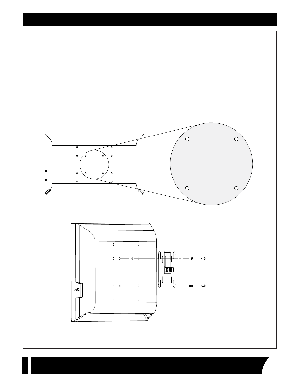
Installation - Small Pattern VESA
ATTACHING VESA PLATE TO MONITOR
Unpack the fixture.
1.
Locate the VESA plate and mounting screws.
2.
On the reverse of the monitor, locate the VESA mounting pattern (figure 1).
3.
Align VESA plate to mounting pattern. Use provided screws to attach the VESA plate to the monitor.
4.
Make sure that the attached VESA bracket angle is facing away from the monitor and that it is
oriented to achieve the desired fixture position (figure 2).
NOTE: Flip VESA bracket for additional height options
Figure 1 - 100mm VESA pattern shown
Figure 2 - Attaching VESA plate to monitor
580 Mayer Street, Building #7, Bridgeville, PA 15017 • Phone: 412.206.0106 • Fax: 412.206.0146
© 2011 Brightline, LP All rights reserved. Patent pending.www.brightlines.com
3
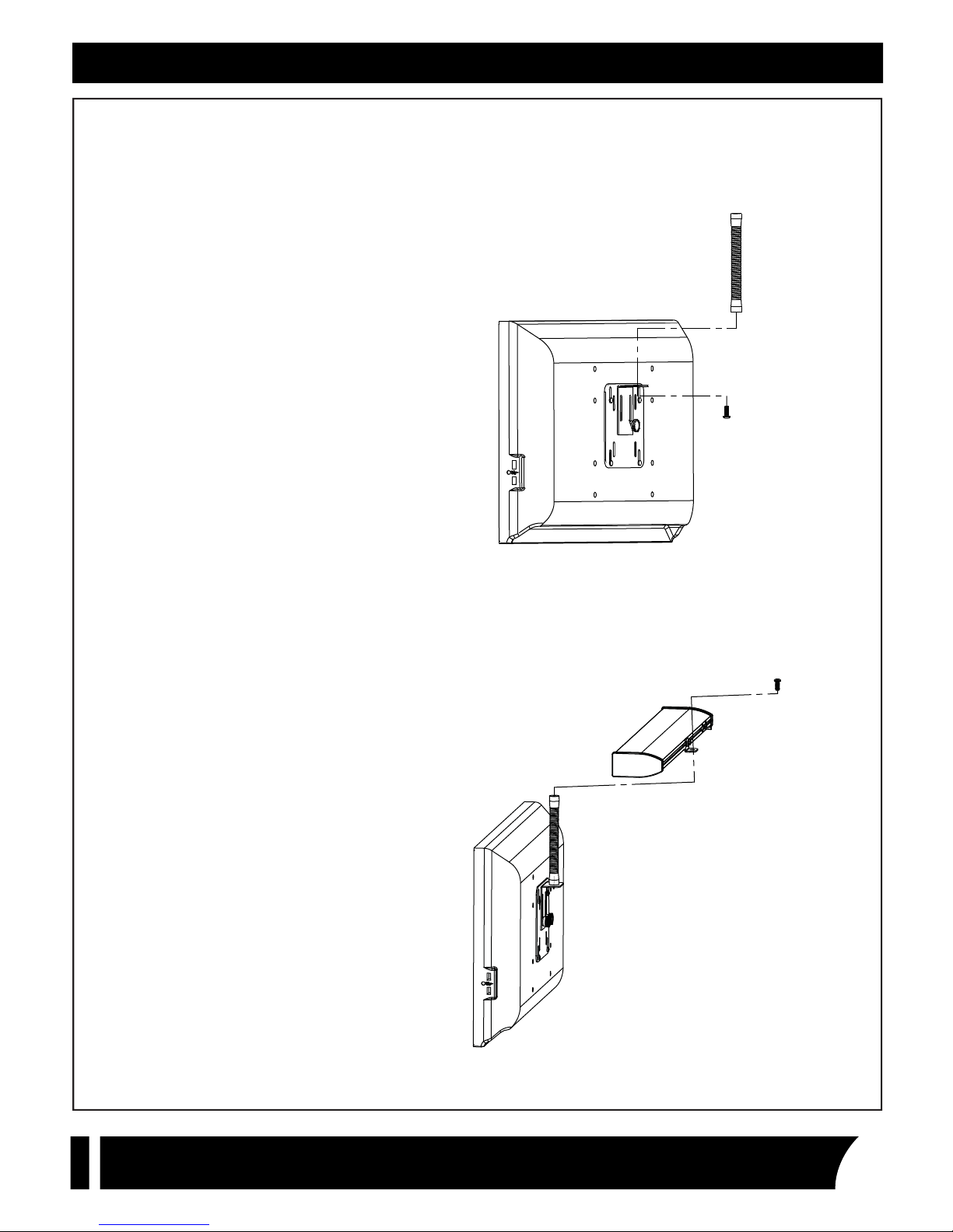
Installation - Small Pattern VESA
ATTACHING THE FLEX ARM
Using the bracket angle, the provided screw, and
the provided Allen wrench, attach the flex arm to
the bracket angle as shown (figure 3).
ATTACHING THE FIXTURE
Attach to the fixture to the flex arm with the
provided screw. Secure through bracket on the
back of the fixture (figure 4).
Figure 3 - Attaching the flex arm to the VESA plate
580 Mayer Street, Building #7, Bridgeville, PA 15017 • Phone: 412.206.0106 • Fax: 412.206.0146
Figure 4 - Attaching the fixture to the flex arm
© 2011 Brightline, LP All rights reserved. Patent pending.www.brightlines.com
4
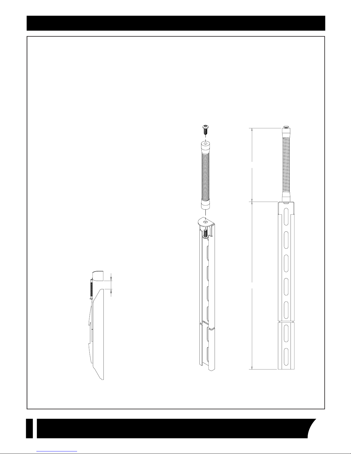
Installation - Large Pattern VESA
ATTACHING FLEX ARMS TO BRACKETS
It’s strongly recommended that you attach the
flex arms to the brackets before attempting any
installation. You can use the top of the flex arm to
guage the approximate location of the fixture
when adjusting the height on the brackets.
Locate the flex arms, brackets and hex head
1.
screws.
2.
Use the provided Allen wrench to attach each
flex arm to a bracket.
3.
Insert, but do not over tighten, the remaining
hex head screws into the top of both flex
arms.
6.18”
Note the dimensions in figure 7 when positioning
the brackets. If the top flange of the bracket falls
below 6” under the top of the display, there may
be interference with the i-Series fixture. To
achieve the best possible user experience, install
the brackets so that 1” to 3” of the flex arm are
exposed above the display. This will provide the
best possible articulation (figure 5).
1“ - 3”
14.13”
580 Mayer Street, Building #7, Bridgeville, PA 15017 • Phone: 412.206.0106 • Fax: 412.206.0146
Figure 6 - Assembling the bracket and flex armFigure 5 - Recommended Height Figure 7 - Bracket dimensions
© 2011 Brightline, LP All rights reserved. Patent pending.www.brightlines.com
5
Installation - Large Pattern VESA
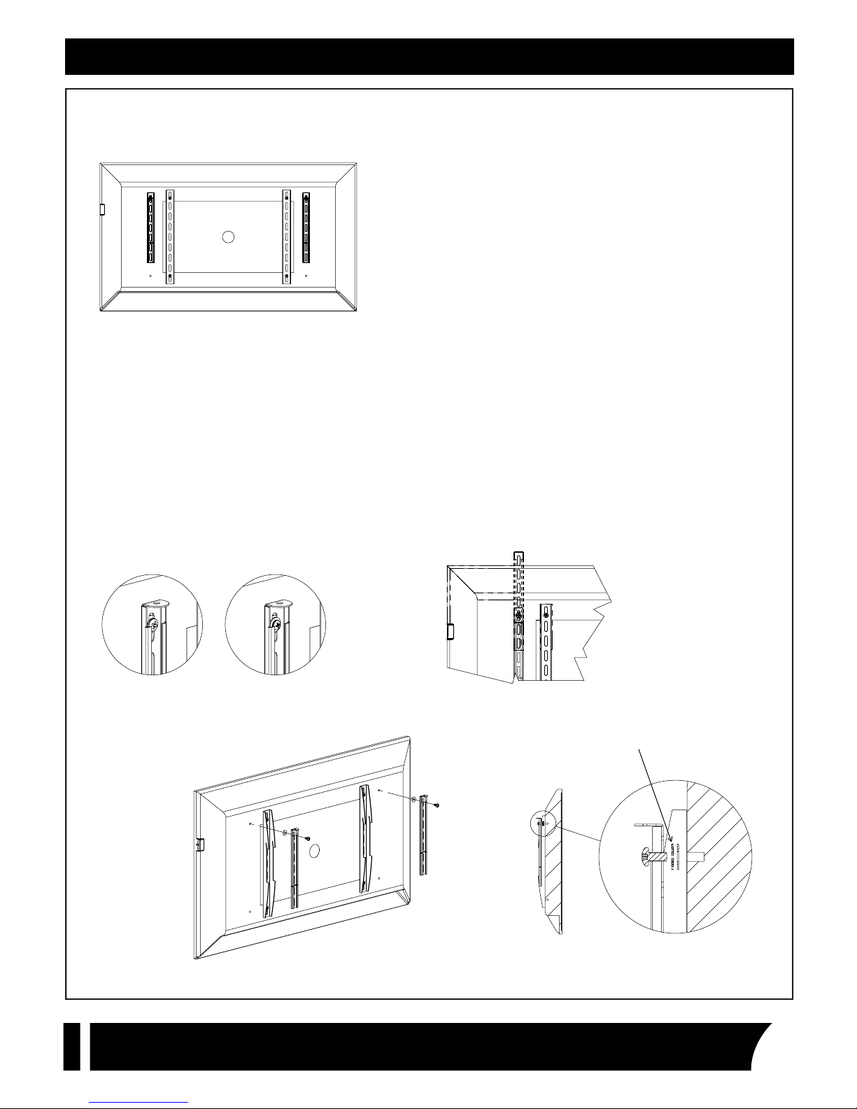
INSTALLING BRACKETS WITH AVAILABLE VESA HOLES
If your display has multiple VESA patterns (e.g., 400x600 &
400x800) or if your display is not wall-mounted, you may
mount the i-Series brackets to the unused holes without
uninstalling your existing VESA bracket (if applicable).
Unpack fixture and and accessories.
1.
Unmount your display (If necessary) and place face-down on a clean, soft surface.
2.
If your display takes size M6 screws, use the M6x12mm screws to mount the brackets. If your display takes
3.
size M8, use the M8x16mm screws. When using the M6, you must also use the metal washer (figure 8).
Take two (2) nylon washers and align them with the topmost unused holes. They should be evenly spaced
4.
from the center (figure 9). If you have more than one set available, use the widest set.
Position bracket with flat side facing display. Align appropriate slot with the hole depending on your
5.
height requirement (figure 10). Use only the top five (5) slots.
Secure with screws provided. Ensure brackets are parallel before tightening. If your mounting hole is too
6.
shallow, insert another nylon washer (figure 11). Add only as many as you need. Screw should be as deep
as possible.
Figure 8 - LEFT: M8 - RIGHT: M6 with washer
Figure 9 - Components in line with mount holes
580 Mayer Street, Building #7, Bridgeville, PA 15017 • Phone: 412.206.0106 • Fax: 412.206.0146
Figure 10 - Adjusting height of bracket
© 2011 Brightline, LP All rights reserved. Patent pending.www.brightlines.com
Figure 11 - Additional washer
6

Installation - Large Pattern VESA
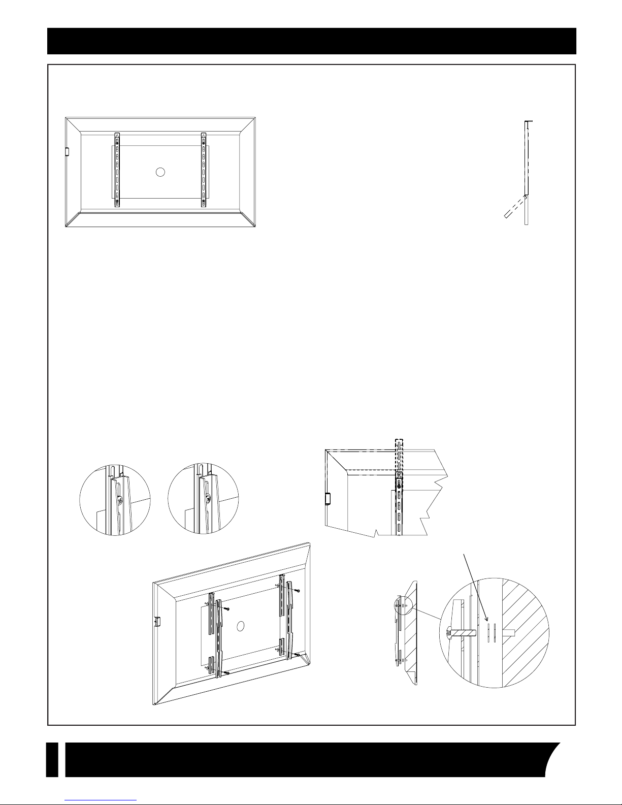
INSTALLING BRACKETS WITH EXISTING VESA BRACKETS
If your display has only one VESA pattern and it
is in use by an existing VESA bracket, you may
install the i-Series bracket one of two ways. If the
VESA bracket is wide enough and there is no
interference with the mounting apparatus
(figure 12), then the i-Series bracket can nest
within the VESA bracket. If the VESA bracket is
too narrow or too shallow or otherwise incompatiple with this method, please see page 3.
Unpack fixture and and accessories.
1.
Unmount your display (If necessary) and place face-down on a clean, soft surface.
2.
If your display takes size M6 screws, use the M6x16mm screws to mount the brackets. If your display takes
3.
size M8, use the M8x20mm screws. When using the M6, you must also use the metal washer (figure 13). If
the screws used to install your VESA brackets are longer than our provided size, you may reuse them.
Remove all screws used to install your VESA bracket. Separate them from the screws provided with the
4.
i-Series bracket.
Take four (4) nylon washers and align them with the VESA holes (figure 14).
5.
Reposition VESA brackets on top of nylon washers. Position i-Series brackets in VESA brackets with flat
6.
side facing display. Align appropriate slot with the topmost hole depending on your height requirement
(figure 15). Use only the top five (5) slots.
Secure VESA bracket and i-Series bracket with screws provided. Ensure brackets are parallel before tight-
7.
ening. If your mounting hole is too shallow, insert another nylon washer for each screw (figure 16). Add
only as many as you need. Screw should be as deep as possible.
Figure 12 - i-Series
bracket nested inside
VESA bracket : no interference
.4375”
Figure 13 - LEFT: M8 - RIGHT: M6 with washer
Figure 14 - Components in line with mount holes
580 Mayer Street, Building #7, Bridgeville, PA 15017 • Phone: 412.206.0106 • Fax: 412.206.0146
Figure 15 - Adjusting height of bracket
© 2011 Brightline, LP All rights reserved. Patent pending.www.brightlines.com
Figure 16 - Additional washer
7
Installation - Large Pattern VESA
INSTALLING BRACKETS WITH EXISTING VESA BRACKETS (PART 2)
If your display has only one VESA pattern and it
is in use by an existing VESA bracket, you may
install the i-Series bracket one of two ways. If the
VESA bracket is too narrow to nest the i-Series
bracket inside it or if the mounting aparatus
would interfere with the i-Series bracket if
nested, you may mount the bracket between the
VESA brackets and the display.
Unpack fixture and and accessories.
1.
Unmount your display (if necessary) and place face-down on a clean, soft surface.
2.
Take i-Series bracket and snap off lower portion on each (figure 17). Do not discard either portion.
3.
If your display takes size M6 screws, use the M6x25mm screws to mount the brackets. If your display takes
4.
size M8, use the M8x30mm screws. When using the M6, you must also use the metal washer (figure 18). If
the screws used to install your VESA brackets are longer than our provided size, you may reuse them.
Remove all screws used to install your VESA bracket. Separate them from the screws provided with the
5.
i-Series bracket.
Take four (4) nylon washers and align them with the VESA holes (figure 19).
6.
Position i-Series brackets with flat side facing display. Align appropriate slot with the topmost hole
7.
depending on your height requirement (figure 20). Use only the top five (5) slots. Use the smaller,
snapped-off portion as a shim on the lower holes.
Reposition VESA brackets on top of i-Series brackets. Make sure the VESA bracket is fully supported by
8.
both the i-Series bracket and the shim.
Secure with screws provided. Ensure brackets are parallel before tightening. If your mounting hole is too
9.
shallow, insert another nylon washer for each screw (figure 21). Add only as many as you need. Screw
should be as deep as possible.
Figure 17 - Bend back and
forth to snap off
Figure 18 - LEFT: M8 - RIGHT: M6 with washer
Figure 19 - Components in line with mount holes
580 Mayer Street, Building #7, Bridgeville, PA 15017 • Phone: 412.206.0106 • Fax: 412.206.0146
Figure 20 - Adjusting height of bracket
© 2011 Brightline, LP All rights reserved. Patent pending.www.brightlines.com
Figure 21 - Additional washer
8

Installation - Wall
INSTALLING BRACKETS TO WALL BEHIND DISPLAY
1.
Unpack fixture and and accessories.
2.
Mount your display, if it is not already mounted, and mark its top edge on the wall behind it. Use a tape
measure to find the center line. Unmount your display and put aside in a safe place.
3.
Place one i-Series bracket against wall with round flange facing up and position to your preference. This
flange shoud be no lower than 5” below the line indicating the top of the display (figure 22).
4.
Mark the two slots indicated in figure 23 and mark a line indicating the top flange of the bracket. Measure
the distance from the center.
5.
Repeat for the other bracket, using the line you marked for the top flange as a reference. Brackets must
be no less than 20” apart for the I-36 and the I-46. Brackets must be no more than 32” apart for the I-36
and no more than 44” apart for the I-48 (figure 3).
6.
Install bracket hardware as determined by what type of surface to which you are mounting.
When you are unable or unwilling to use any of the VESA mount
options, you may also mount the brackets to a wall behind the
display. Brightline does not provide any hardware for wallmounting your i-Series brackets. It is recommended that you
consult with a professional regarding the correct type of
hardware to suit your needs. Make sure your hardware will fit.
NOTE: With wall mounting, you will need to bend the goosenecks forward so that the power connector
does not press into the wall when plugged in. This is normal. Typical large display i-Series installations
require that the fixture is bent forward to illuminate the target as best as possible.
.34”
5.00”
1.10”
USE THESE SLOTS
.75”
Figure 22 - Adjusting height
Figure 23 - Mounting Bracket
Figure 24 - Maximum mounting distance
I-36: MAX 32”
I-48: MAX 44”
580 Mayer Street, Building #7, Bridgeville, PA 15017 • Phone: 412.206.0106 • Fax: 412.206.0146
© 2011 Brightline, LP All rights reserved. Patent pending.www.brightlines.com
9

Installation - Large Pattern VESA
ATTACHING THE FIXTURE
NOTE: It is recommended that you have one other
person assist in the installation.
Measure the distance between the two flex arms
1.
from the center of one screw the the center of the
other (figure 25).
Loosen nuts on the brackets on the back of the
2.
fixture (figure 26).
Slide the brackets to the distance measured from
3.
the display. Double check by holding the fixture
over the flex arms. Retighten the nuts (figure 27).
Remove hex head screws from the tops of the flex
4.
arms.
While one person holds the fixture in place, attach
5.
fixture to flex arms with the provided hex head
screws. Tighten with Allen wrench.
Figure 25 - Measure the distance
Figure 26 - Nuts on sliding brackets
Figure 27 - Postion the brackets
580 Mayer Street, Building #7, Bridgeville, PA 15017 • Phone: 412.206.0106 • Fax: 412.206.0146
Figure 28 - Assembly with a multi-pattern VESA setup
© 2011 Brightline, LP All rights reserved. Patent pending.www.brightlines.com
10

Intallation
Insert the plug into the fixture and into the wall. Use the control on the power cord to dim and to turn the
fixture on and off (figure 29).
POWERING THE FIXTURE
Figure 29 - Powering a fixture with a small VESA bracket
580 Mayer Street, Building #7, Bridgeville, PA 15017 • Phone: 412.206.0106 • Fax: 412.206.0146
© 2011 Brightline, LP All rights reserved. Patent pending.www.brightlines.com
11

WARRANTY
Brightline guarantees all its products to be free from defects in materials and
workmanship for a period of one (1) year from the date of shipment.
PROCEDURES
If any product is found to be unsatisfactory under this warranty, the buyer must notify
Brightline immediately. Once a course of action has been determined, if it is necessary
to return the product to Brightline , a Return Authorization (RA) will be issued. Ship the
product directly to
RA
number should be marked on the shipping carton. The unit will be replaced or put into
proper operating condition, free of charges. The correction of any defects through repair
replacement by Brightline shall constitute fulfillment of all obligations and liability of
or
Brightline to the buyer under this warranty and the contract of sale.
Brightline, 580 Mayer Street, Building #7, Bridgeville, PA 15017. The
DISCLAIME
Brightline is not responsible for damage to its products caused by improper installation,
tenance, or use; by improper electrical hookups; or by unauthorized repairs.
main
Failure to notify Brightline of unsatisfactory operation or any improper or unauthorized
tallation, maintenance, use, repairs, or adjustments shall terminate the warranty and
ins
Brightline shall have no further responsibility under the warranty.
Brightline shall not be liable for special or consequential damages in any claim, action,
suit, or p
lia
to replacement. Brightline makes no other warranty of any kind whatsoever, expressed
or implied, and all implied
pu
disclaimed
All shipments, unless otherwise noted, are F.O.B. factory.
The customer is advised to inspect for shipping damage, apparent and/or hidden. If
de
roceeding arising under this warranty or contract of sale, nor shall
ble for claims of labor, loss of profits or goodwill, repairs, or other expenses incidental
warranties of mechantability and fitness for a particular
rpose that exceed the obligation specifically described in this warranty are hereby
by Brightline and excluded from this agreement.
tected, notify the transportation company and file your claim.
RS
Brightline be
580 Mayer Street, Building #7, Bridgeville, PA 15017 • Phone: 412.206.0106 • Fax: 412.206.0146
© 2011 Brightline, LP All rights reserved. Patent pending.www.brightlines.com
12
 Loading...