

Page 1
M3500 Issue 2 - Feb 2006
Last reviewed: Oct 2010 / Next review Oct 2013
1
Operating, Maintenance and
Spare Parts Manual for the
Bright
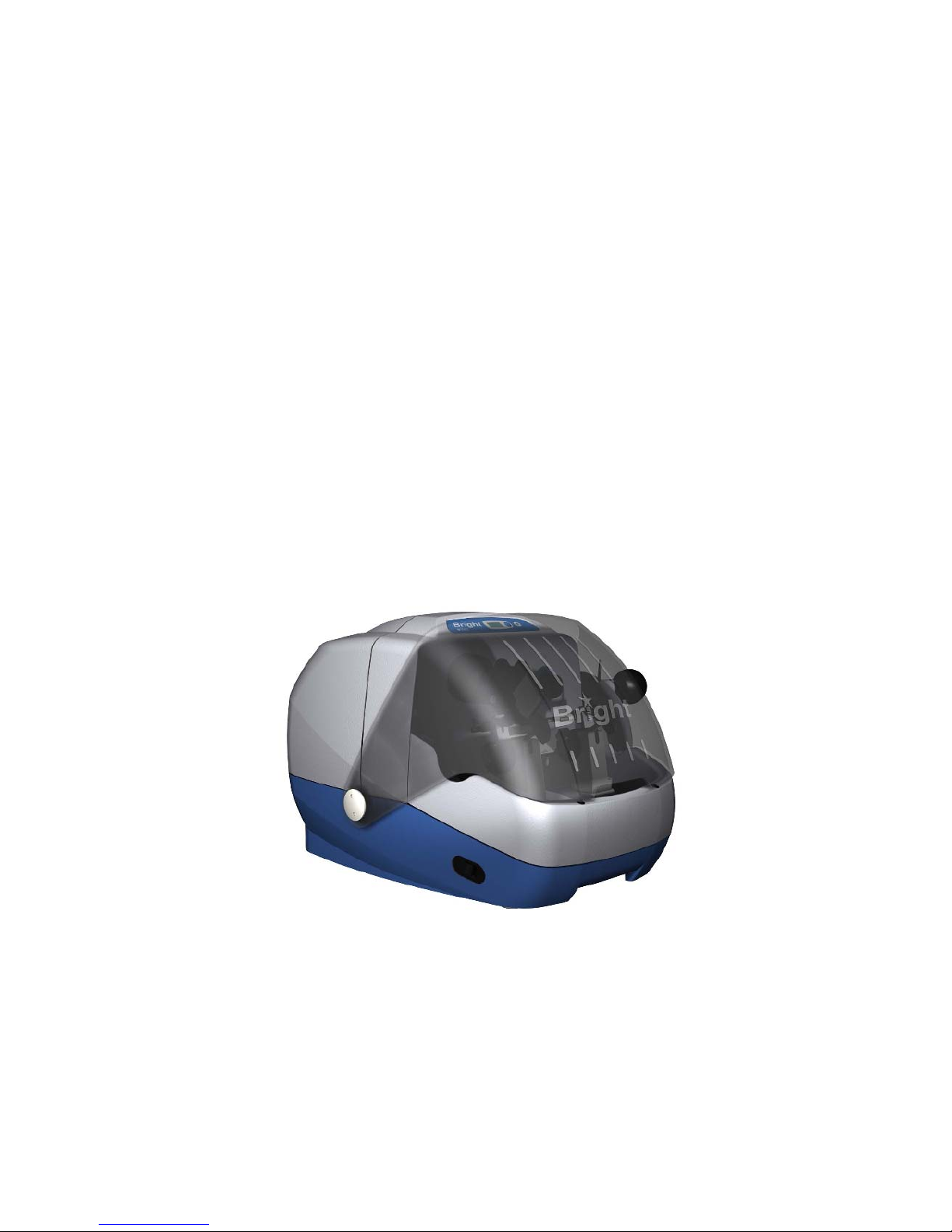
M3500 MICROTOME
Serial Number: ………………………
Page 2

M3500 Issue 2 - Feb 2006
Last reviewed: Oct 2010 / Next review Oct 2013
2
CONTENTS
OPERATING, MAINTENANCE AND .............................................................. 1
SPARE PARTS MANUAL FOR THE .............................................................. 1
BRIGHT ........................................................................................................... 1
M3500 MICROTOME ....................................................................................... 1
Serial Number: ……………………… ................................................................................................. 1
CONTENTS ........................................................................................... 2,3 & 4
SAFETY AND GENERAL INFORMATION ..................................................... 6
Consumer Protection .......................................................................................................................... 6
ELECTRICAL .................................................................................................................................... 6
MICROTOME KNIVES/BLADES ...................................................................................................... 6
OPERATION .......................................................................................................................................... 7
ACCESSORIES ...................................................................................................................................... 7
PRODUCT SAFETY SUGGESTIONS ................................................................................................ 7
DECONTAMINATION CERTIFICATES .......................................................................................... 7
WARRANTY .......................................................................................................................................... 8
1. INTRODUCTION ....................................................................................... 9
1.1 Receipt and Unpacking ...................................................................................................... 9
1.1.1 Receipt ............................................................................................................................. 9
1.1.2 Unpacking ....................................................................................................................... 9
1.1.3 Lifting .............................................................................................................................. 9
1.2 ASSEMBLY AND INSTALLATION ........................................................ 9
1.2 Electrical connections ......................................................................................................... 9
1.2.1 Electrical requirements .................................................................................................. 9
1.2.2 Electrical Safety .............................................................................................................. 9
1.2.3 Switching on .................................................................................................................... 9
2. OPERATING INSTRUCTIONS .................................................................. 9
2.1 Front Control Panel .......................................................................................................... 10
2.2 REAR FUSE PANEL ............................................................................ 10
2.1.1 Mains Switch ................................................................................................................. 10
2.1.2 Fuse ................................................................................................................................ 10
2.3 PRE-USE CHECKS .............................................................................. 11
2.4 MICROTOME CONTROLS ................................................................... 11
2.4.1 Specimen cassette .......................................................................................................... 11
2.4.2 Knife Holder .................................................................................................................. 11
2.4.3 Disposable Blades ......................................................................................................... 11
2.4.4 Rewind Control (Manual) ............................................................................................ 12
2.4.5 Section Thickness Control ........................................................................................... 12
Page 3

M3500 Issue 2 - Feb 2006
Last reviewed: Oct 2010 / Next review Oct 2013
3
2.5 MOTORISED ADVANCE/REWIND (WHERE FITTED) ........................ 12
2.5.1 General .......................................................................................................................... 12
2.5.2 Motorised Specimen Cassette Rewind ........................................................................ 12
2.5.3 Motorised Specimen Cassette Advance ...................................................................... 12
2.6 OTHER FEATURES ............................................................................. 12
2.6.1 Debris Trays .................................................................................................................. 12
2.6.2 Visor ............................................................................................................................... 13
2.6.3 Hand wheel .................................................................................................................... 13
2.7 CUTTING AND COLLECTING SECTIONS .......................................... 13
2.7.1 Set Up ............................................................................................................................. 13
2.7.2 Wax Cassette Set Up ..................................................................................................... 13
2.7.3 Trimming ....................................................................................................................... 13
2.7.4 Section Cutting .............................................................................................................. 13
3. GENERAL MAINTENANCE .................................................................... 14
3.1 Daily Care .......................................................................................................................... 14
3.2 Microtome Knives and Blades ......................................................................................... 14
3.2.1 Conventional Knives ..................................................................................................... 15
3.2.2 Disposable Blades ......................................................................................................... 15
3.3 SERVICING AND REPAIRS ................................................................. 15
3.3.1 Routine Servicing .......................................................................................................... 15
3.3.2 Repairs ........................................................................................................................... 15
3.4 DECONTAMINATION .......................................................................... 16
3.4.1 Disinfectant ................................................................................................................... 16
4. SECTIONING ........................................................................................... 16
A PROBLEM SOLVING QUIDE ....................................................................................................... 16
4.1 CHECK LIST ........................................................................................ 16
4.1.1 Specimen ........................................................................................................................ 16
4.1.2 Knife............................................................................................................................... 16
4.1.3 General Factors ............................................................................................................. 16
4.2 THICK / THIN SECTIONS .................................................................... 17
INTERMITTENT FAILURE TO CUT .............................................................................................. 17
4.3 SECTIONS CRUMBLING OR NOT FORMING .................................... 17
4.4 EXCESSIVE COMPRESSION OF SECTIONS ..................................... 17
4.5 UNEVEN THICKNESS ACROSS SECTION ........................................ 17
4.6 VERTICAL SCORE MARKS ON SECTIONS ....................................... 17
4.7 SECTIONS FAIL TO FLATTEN AND PASS DOWN KNIFE ................ 18
5.0 MISCELLANEOUS SERVICING INSTRUCTIONS .............................. 18
5.1 Advance Pawl Replacement ............................................................................................. 18
5.2 Pawl Release Lever (Advance)......................................................................................... 18
Page 4

M3500 Issue 2 - Feb 2006
Last reviewed: Oct 2010 / Next review Oct 2013
4
5.3 Calibration ........................................................................................................................ 18
9. SPECIFICATIONS ..................................................................................... 21
Accessories ........................................................................................................................................ 22
MATERIAL SAFETY DATA SHEET ............................................................. 23
Name: CRYO-M-BED .............................................................................................................. 23
MATERIAL SAFETY DATA SHEET ............................................................. 24
Name: CRYOSPRAY ............................................................................................................... 24
MATERIAL SAFETY DATA SHEET ............................................................. 25
Name: Low temperature Grease ............................................................................................. 25
Knives / Blades .................................................................................................................................. 26
DECONTAMINATION CERTIFICATE ........................................................... 27
DECONTAMINATION PROCEDURES ......................................................... 28
Microtomes ............................................................................................................................................ 28
Microtome Knives ................................................................................................................................ 28
QUALITY SURVEY REPORT........................................................................ 29
Annexe:
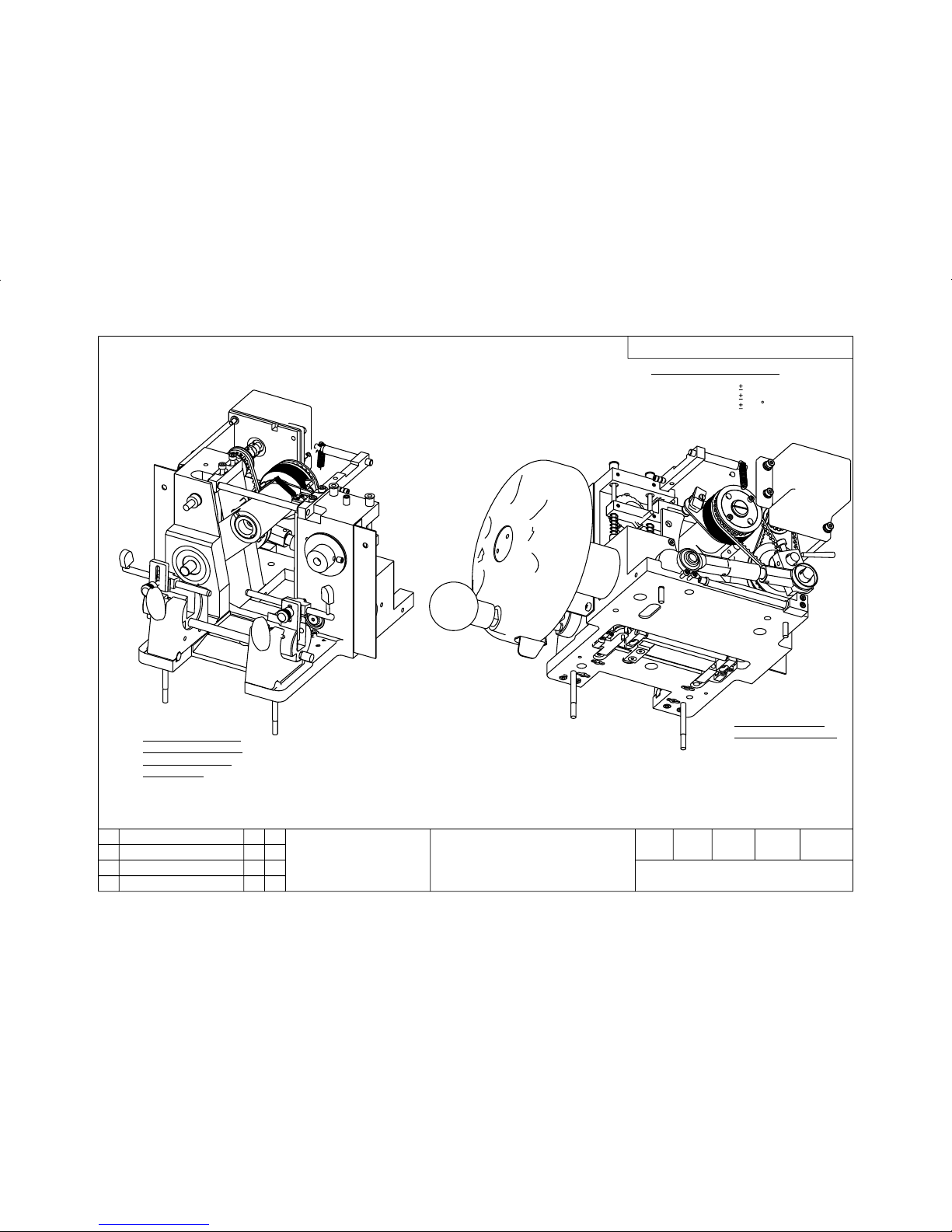
Drawing 212-040 M3500 Microtome Assembly 1 of 3 30, 31 & 32
Part List 212-040-PL 33 & 34
Drawing 51937 Cutting Arm Assembly 35
Part List 51937-PL 36
Drawing 212-041 Microtome Motor Rewind Sub-Assembly 37
Part List 212-041-PL 38
Drawing 212-046 CQRS Non-Orientating Assembly 39
Part List 212-046-PL 40
Drawing 212-047 CQRS Orientating Head Assembly M3500 41
Part List 212-047-PL 42
Drawing 212-051 Pawl Release Assembly 43
Part List 212-051-PL 44
Drawing 212-054 M3500 Knife Block Retract Model Sub-Assembly 45
Part List 212-054-PL 46 & 47
Drawing 212-061 M3500 Input Drive Shaft (Hand wheel) Assembly 48
Part List 212-061-PL 49
Wiring Diagram 50
Page 5
M3500 Issue 2 - Feb 2006
Last reviewed: Oct 2010 / Next review Oct 2013
5
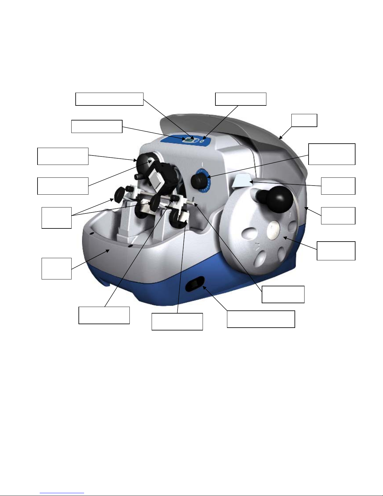
Power Indicator Section Counter Reset
Section Counter
Visor
Thickness
Selector Knob
Locking
L
eve
r
Rear
Cove
r
Cutting
Handwheel
RH Advance/Rewind
Switc
h
50230 Standard
Knif
e
RH Knife
Guard
Knife Guard
H
eight
Knob
Debris
Tray
Knife
Clamps
Cassette Release
L
eve
r
Manual
A
dv/Rwd
Knob
Page 6

M3500 Issue 2 - Feb 2006
Last reviewed: Oct 2010 / Next review Oct 2013
6
SAFETY AND GENERAL INFORMATION
Consumer Protection
The Consumer Protection Act 1987 Part 1. refers to Product Liability. This legislation was
issued as a direct result of an EC Directive to all member states and has been in force with
effect from 1 March 1988.
The Bright Instrument Company Limited, ever mindful of the need to ensure that their
products are not subject to misuse and/or incorrect handling, have made it their aim to
communicate any possible dangers to their customers.
Whilst the Bright Instrument Company Limited markets products manufactured to the highest
safety standards, it is in the interest of the purchaser that he is aware of the resultant dangers
of misuse and/or incorrect handling of these products.
Your attention is therefore drawn to the following precautions:
ELECTRICAL
a. Warning - A warning notice is fixed to the instrument (where applicable) stating that
it should be disconnected from the mains supply before removing the panels. This
warning should be strictly observed.
b. Fuses – Fuse ratings are clearly indicated on all fuse panels adjacent to the fuse
holder. If and when replacement is necessary, the correct fuse rating and type must
be adhered to.
c. Earthing (Grounding) – A protective earth terminal is fitted and must be used in all
two-wire installations.
MICROTOME KNIVES/BLADES
The microtome knife/blade can be a hazard in the laboratory. Personnel should be made
aware of the dangers and observe the following warnings:
a. DO NOT leave the microtome unattended with an exposed knife/blade in position.
Remove the knife/blade, or cover with the guards or visor provided.
b. DO NOT leave unboxed knives/blades lying around. Place knives/blades that are not
in use in their boxes or packets.
c. DO NOT carry knives/blades unless secure in the box or packet provided.
d. DO NOT clean the knife/blade along its length. Wipe the knife/blade from the back
edge to the cutting edge.
e. REMEMBER that even used knives and blades are dangerous. The are still sharp
and may have been used to cut potentially infectious specimens.
f. DISPOSE of used knives and blades with the same care as other sharp objects. On
no account should used knives or blades be placed in waste bins.
Page 7

M3500 Issue 2 - Feb 2006
Last reviewed: Oct 2010 / Next review Oct 2013
7
OPERATION
When placing specimen cassettes in the microtome, when orientating, manipulating or in any
way placing fingers in a position above the knife/blade edge – ensure that the hand wheel is
locked and knife guards are in position.
ACCESSORIES
The instrument has the following accessories as standard:
Low temperature grease: (please refer to the material safety data information, towards the
back of this instructions manual, for further information).
Long series ball driver tool, to remove / fit rear cover
2 pin tool, to remove / fit the hand wheel and visor
Allen keys, fuse and brush
PRODUCT SAFETY SUGGESTIONS
All Bright Instrument Company Limited personnel are encouraged to make suggestions
regarding product safety. We also welcome such suggestions from our customers. They may
be submitted by completing the appropriate (Safety) section of the Quality Survey Record
Form supplied with all Bright instruments, or alternatively, by letter, telephone, fax or email. All
communications should be direct to our Quality Assurance Department and will be
acknowledged.
DECONTAMINATION CERTIFICATES
IMPORTANT
If the instrument or any part of it is to be returned to Bright Instrument Company Limited, a
decontamination certificate must accompany it, and please note the following:
1. If the instrument or any part of it has been exposed to or been in contact with potential
pathogenic or radioactive material, it is essential that it be decontaminated.
2. Set procedures are laid down by the Health and Safety Executive for decontamination.
The “Howie code” and the “Code of Practise for the Prevention of Infection in Clinical
Laboratories and Post-mortem Rooms”, ISBN 0 11 320464 7) explain the correct
procedures to be used. For the avoidance of doubt, we ask that a completed
decontamination certificate should accompany instruments or parts returned to us. A copy
of this can be found at the back of this instruction manual and we suggest you use a
photocopy of this when returning parts. Alternatively we would be pleased to either post or
fax you another copy should you require.
3. Should the instrument or any part of it be received in a condition that Bright Instrument
Company Limited, consider to be a potential biological hazard, the instrument or part will
be returned unrepaired at the expense of the customer.
4. Customer’s declarations must indicate that the package contains ‘British Returned
Goods’. Failure to do so will involve customs duty payable by us, which will be invoiced to
the sender.
Page 8

M3500 Issue 2 - Feb 2006
Last reviewed: Oct 2010 / Next review Oct 2013
8
WARRANTY
The Warranty relating to the instrument is outlined in our Terms and Conditions of Sale
paragraph 6.
i) The Seller‘s products are carefully inspected and submitted to its standard tests.
II) The Seller warrants all its products to be free from defects in workmanship and
materials under normal conditions of use and service provided always:
a. that if any of the goods so manufactured is alleged to be defective in workmanship
and material and is returned carriage paid, and protected against damage in transit to
the Seller’s works at Huntingdon, England within 12 months from the date of despatch
and if after examination by the Seller that goods or part of them are found to be so
defective then the Seller will repair or replace them free of charge and will return them
to the Buyer , carriage paid.
b. where any part of the goods manufactured by the Seller is repaired or replaced under
the terms of the foregoing warranty, such warranty shall thereafter be limited to a
period of six months from the date when the goods shall have been re-delivered to
the Buyer.
c. this warranty does not apply to any defects caused by wear and tear, incorrect
installation abnormal conditions of working, accident, misuse or neglect.
d. that save as in this clause herein before expressed, the Seller shall not be under any
liability for negligence or otherwise in respect of defects in goods delivered or for any
injury, damage or loss resulting from such defects and the Seller’s liability under this
clause shall be in lieu of any warranty or condition implied by law as to the quality or
fitness for any particular purpose of such goods.
e. this warranty is expressly in lieu of all other warranties, guarantees or liabilities
expressed or implied by any of the Seller’s Representatives or Agents.
Please see our separate Product Warranty sheet for deliveries to the mainland UK.
WARNING
Before proceeding to Operating Instructions, ensure you are familiar with the contents
of the pages marked ‘Safety Information’. This instrument must only be used by
competent persons.
Page 9

M3500 Issue 2 - Feb 2006
Last reviewed: Oct 2010 / Next review Oct 2013
9
1. INTRODUCTION
1.1 Receipt and Unpacking
This instrument received a final test and inspection prior to despatch from the factory. The
following instructions are given for the re-assembly of the instrument, adjustments and its
correct use. If the instrument is received before preparations for installation are completed, it
should be stored in a clean, dry place and not exposed to dirty or damp conditions.
1.1.1 Receipt
Immediately upon receipt of the instrument, make a careful examination for evidence of
damage encountered in transit. If any damage is found or suspected, notify both the carrier
and Bright Instrument Company Limited.
1.1.2 Unpacking
All packing must be carefully removed and parts checked against the enclosed packing list. If
any damage or discrepancy is noted, please inform our agent/distributor, or Bright Instrument
Company Limited, direct, immediately.
1.1.3 Lifting
The instrument has been designed with two main lifting points as hand holds at the front and
rear of the instrument. The instrument weight less than 25Kgs, but care should be taken when
lifting by following manual handling guide lines. If in doubt contact your Health & Safety
Officer.
1.2 ASSEMBLY AND INSTALLATION
The microtome is delivered virtually ready for use with only the accessories required for use in
need of fitting.
1.2 Electrical connections
1.2.1 Electrical requirements
The supply cord of the instrument should be connected to any ordinary electrical outlet (max
13 amps). Check the voltage stamped on the nameplate, located on the underside of the
instrument, with your supply:
The connections are:
Brown - Positive [live]
Blue - Negative [neutral]
Yellow/Green - Earth [ground]
1.2.2 Electrical Safety
Where earth connections are taken through connectors, then the connector must be rated to
take the maximum fault current. The machine should be disconnected before such connectors
are separated for servicing purposes.
1.2.3 Switching on
Switch on by using the Mains Power switch located on the rear fuse panel. This is applicable
only to Motorised Advance/Rewind models.
For instruments with a section counter only, this is operated by 2 AA batteries located on the
rear panel at the bottom of the plinth.
2. OPERATING INSTRUCTIONS
On receipt of your new Bright instrument, please refer to section 1.1 (Receipt and Unpacking)
and section 1.2 (Assembly and Installation).
Page 10

M3500 Issue 2 - Feb 2006
Last reviewed: Oct 2010 / Next review Oct 2013
10
As part of its policy of continual improvement, Bright Instrument Company Limited, reserves
the right to incorporate changes, or make additions to, without prior notice. There may,
therefore, be minor details differences between the information in this manual and your
instrument. These differences will not affect the safety and use of the instrument.
2.1 Front Control Panel
This panel houses the section counter, the re-set button to zero the counter and a Mains
Power LED for indicating purposes.
2.2 REAR FUSE PANEL
2.1.1 Mains Switch
The mains power switch provides power to the motorised advance/rewind control only.
2.1.2 Fuse
The single fuse is for the Main Power only.
Main - All circuits
If the fuse blows, replace it with a new one of exactly the same rating. In the event of
repeated fuse blowing, consult a qualified electrical engineer.
On NO account must the fuse be replaced with anything other than a correctly rated
substitute.
Page 11
M3500 Issue 2 - Feb 2006
Last reviewed: Oct 2010 / Next review Oct 2013
11
2.3 PRE-USE CHECKS
With the instrument on the work surface open the visor and ensure that the cutting arm will
strike no objects. With the section thickness dial set at zero and using the mechanical
advance/rewind knob, advance the lead screw body from the cutting arm.
Unlock the hand wheel and rotate in direction of arrow. Ensure hand wheel runs smoothly and
the section counter is operating.
For models with Motorised Advance/Rewind, ensure you have the correct power supply and
fuse rating before plugging in and applying power.
With power applied ensure the section thickness dial is set at zero and the cutting arm in the
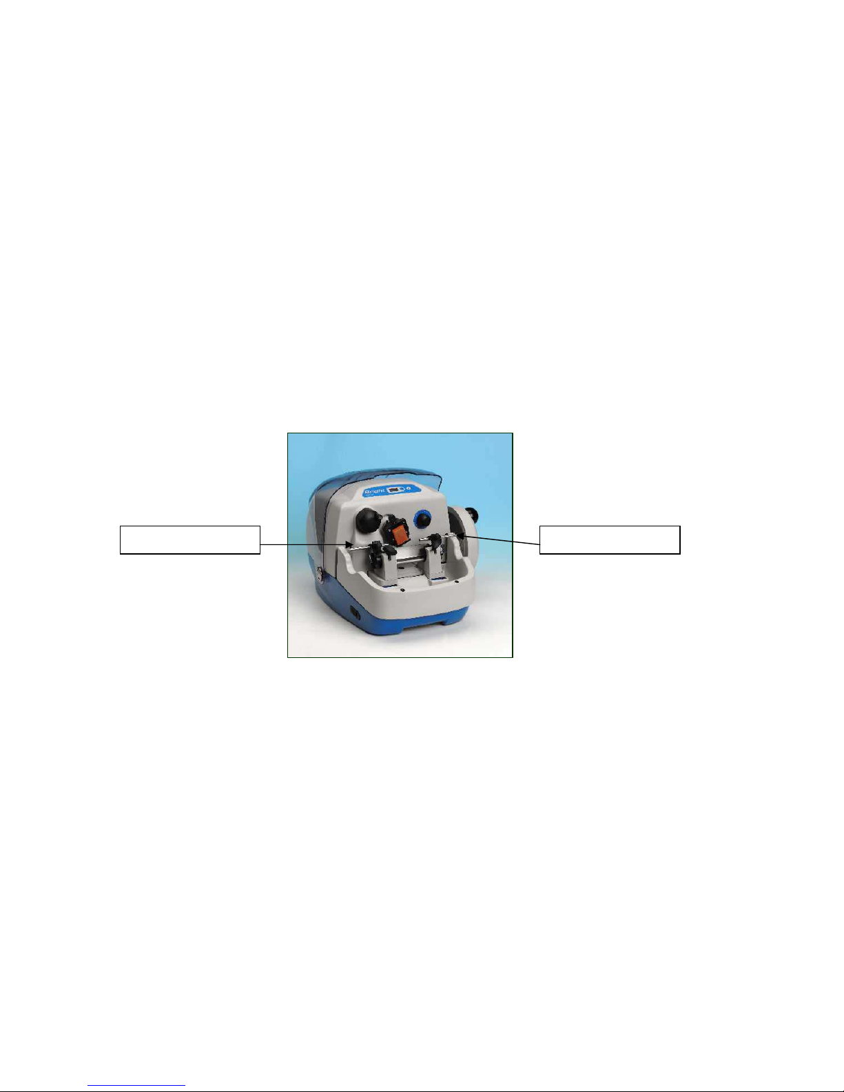
top position, repeat operation above using either of the Advance/Rewind switches located on
the left hand and right hand side of the Plinth.
2.4 MICROTOME CONTROLS
2.4.1 Specimen cassette
IMPORTANT: Ensure knife guards are in a central position if a knife is installed.
To install a specimen cassette, pull the release lever forward with your finger. Place the
cassette in position and release the lever.
To orientate (if option ordered) the specimen cassette, move the lever to the left to release
the clamp, then move the cassette to the desired position. Re-lock the lever.
2.4.2 Knife Holder
To install a knife or disposable blade holder, loosen the clamp screws, slide the knife guards
to the centre, and slide knife through from the left.
Before re-tightening clamp screws, set knife tilt angle (against the degree scale graduated 025º). The correct setting of the knife tilt angle is essential for obtaining good results. With a
Bright 50230 knife, set an angle of 15º. With a Bright Lever Release Feather Blade Holder cat
no. 57903 the angle should be set to 5º.
2.4.3 Disposable Blades
The M3500 can be fitted with the Bright ‘Magnacut’ disposable blade system (not
recommended on Wax) or with a suitable alternative holder for ‘Feather’ blades, some
experimentation may be required for optimum results. Generally a knife tilt angle of 5º is a
good starting point.
Push towards centre Push towards centre
Page 12

M3500 Issue 2 - Feb 2006
Last reviewed: Oct 2010 / Next review Oct 2013
12
IMPORTANT: Knife guards must be used whenever a knife or disposable blades are in
position. Take care to guard the central portion of the knife whenever sections are not being
cut.
2.4.4 Rewind Control (Manual)
The rewind control is used to reset the microtome advance system and for trimming
specimens.
NB: Lock the hand wheel in the three o’clock position and section thickness to zero – this
ensures the advance mechanism is disengaged.
2.4.5 Section Thickness Control
Select section thickness required by turning the knob to the appropriate position. There are
increments of 2µm for 2 - 30µm (or if option ordered for 1µm for 1 -15µm lead screws).
2.5 MOTORISED ADVANCE/REWIND (where fitted)
2.5.1 General
The motor used on this machine is a Pulse DC Stepper Motor. As with all stepped motors,
there is an inherent noise which you may find distracting at first. This minimal noise is caused
by the ’pulsing’ of the motor which is particularly noticeable when the motor is no longer
‘driving’. It in no way affects the operation of the microtome, or has any other adverse effects.
The motor is operated by using either of the two switches located on the left and right hand
sides of the Plinth.
The Motorised Advance/Rewind should only be operated with the cutting head below
the 3 o’clock position and the section thickness control set to 0.
2.5.2 Motorised Specimen Cassette Rewind
- to rewind the cassette follow instructions above
- for small rewind increments, press and quickly release the switch.
2.5.3 Motorised Specimen Cassette Advance
- set specimen thickness control to 0µm
- rewind specimen as required
- with microtome knife set at the correct angle with the specimen in position, use the
switch to ‘advance’ until a minimum clearance has been achieved
- begin trimming by pressing and releasing ‘advance’ switch whilst rotating hand wheel
2.6 OTHER FEATURES
2.6.1 Debris Trays
Two debris trays are provided – one is the internal part of the microtome that surrounds the
knife block.
The second tray is internal and sits under the Main Cutting Arm with the sole purpose of
collecting any stray debris that may have found its way past the Debris Blind. To access the
second tray, you must remove the External Debris Tray.
Page 13

M3500 Issue 2 - Feb 2006
Last reviewed: Oct 2010 / Next review Oct 2013
13
The debris trays can easily be lifted out for emptying and cleaning, but first brush most of the
debris into the deeper sections of the trays.
Do not expose the trays to temperatures in excess of 60ºC (see section 3.4)
2.6.2 Visor
The visor is a plastic translucent moulding which can be usd as a safety feature by closing
when the unit is not in use to prevent someone inadvertently touching the settings, blade etc.
2.6.3 Hand wheel
The operating hand wheel on the right side of the Microtome can be locked with the thumb
lever. There are ten locking positions including tip and bottom. The hand wheel should always
be turned clockwise.
2.7 CUTTING AND COLLECTING SECTIONS
We recommend the following cutting angles when using:
a. leaver release Feather blade - 5º
b. solid knife [Bright 50230] - 15º
2.7.1 Set Up
- fit a sharp knife in position, ensuring knife guards are in central position
- check hand wheel is locked with specimen cassette in top position
- move knife guards to the side
2.7.2 Wax Cassette Set Up
- place the wax cassette in the quick release holder with the angled end pointing down
- set the section thickness to zero
- slowly turn the operating handle to lower the cassette in proximity to the blade or
knife
- wind the advance/rewind control to take the wax block so that it just touches the back
of the blade or knife. At the same time move the operating hand wheel with a gentle
backwards and forwards motion so that the cassette goes gently up and down.
2.7.3 Trimming
- use the advance/rewind control to carefully increment the wax cassette towards the
blade or knife while fully turning the operating hand wheel. Avoid taking too large
‘bites’ at the wax.
- alternatively, if Motorised advance/rewind is fitted, the wax cassette can be
incremented towards the blade or knife by briefly pressing one of the advance/rewind
switches.
- Another method is simply to set the section thickness control to 14µm and turn the
operating hand wheel until the specimen is suitably exposed.
Take care while trimming , particularly with small specimens or hard/tough tissues.
2.7.4 Section Cutting
- after trimming, set the section thickness control to the desired position and turn the
operating hand wheel slowly
Page 14

M3500 Issue 2 - Feb 2006
Last reviewed: Oct 2010 / Next review Oct 2013
14
- once sections are seen to be cut as required proceed to cut sections
NB: For best results the wax cassettes should be cooled to their optimum sectioning
temperature
Keep the knife clear of debris by brushing upwards with the knife cleaning brush. NEVER
brush along the knife, always brush upwards.
3. GENERAL MAINTENANCE
3.1 Daily Care
Routine daily care consists of removing sectioning debris from the working area, brushing
debris from the knife and cleaning as appropriate.
- first remove the microtome knife/blade holder and clean it (see section 3.4)
- remove the debris trays and clean
- wipe covers and remove excess debris as required
- wipe visor if required
Note that the microtome requires no other routine maintenance.
3.2 Microtome Knives and Blades
Great care must be exercised when handling knives and or disposable blades.
- knives/blades must be stored in their boxes when not in use
- knives /blades fitted to the microtome must be properly guarded
- particular care must be taken during cleaning and knife sharpening
Page 15

M3500 Issue 2 - Feb 2006
Last reviewed: Oct 2010 / Next review Oct 2013
15
3.2.1 Conventional Knives
Conventional microtome knives are usually made from carbon steel and will corrode in moist
conditions
Bright Instrument Company Limited offer a knife sharpening service, please contact Sales for
further information.
3.2.2 Disposable Blades
Take particular care to clean the contact surfaces of disposable blade holders. A build up of
debris can prevent the blade from seating properly and cuases instability during section
cutting.
3.3 SERVICING AND REPAIRS
3.3.1 Routine Servicing
With the exception of items mentioned in section 3.1, there is no requirement for periodical
checks.
3.3.2 Repairs
In the event of a breakdown, a qualified person should be called. For electrical and
mechanical problems contact either your local agent/distributor or bright Instrument Company
Limited. Please provide the following information:
Model
Serial Number
Date of Installation
Nature of Fault
The following tasks can be carried out by competent personnel:
- changing fuses
1. switch off power
2. unscrew fuse holder
3. replace fuse with correct fuse rating
4. screw back in fuse holder
If the microtome or any part of it is returned to the agent/distributor or manufacturer, it is
important to observe the precautions in section 3.4 to minimise the risk of infection.
NB: A completed decontamination certificate must be attached to the exterior of the
microtome. Work on the instrument will not proceed until satisfactory notification of
decontamination has been received.
Page 16

M3500 Issue 2 - Feb 2006
Last reviewed: Oct 2010 / Next review Oct 2013
16
3.4 DECONTAMINATION
It is the responsibility of the user to ensure that a decontamination procedure is employed
which is appropriate to the nature of the work carried out.
Hypochlorite (bleach) solutions are corrosive to many metals and should be avoided.
Do not expose the debris trays to temperatures in excess of 60ºC.
3.4.1 Disinfectant
There are many wide-spectrum biocidal disinfectants on the market that are used in
microbiological and clinical departments. These may be used to disinfect the microtome.
- Make up the solution according to the manufacturers instructions
- Wipe around the microtome with a cloth or paper towel wetted with the solution.
Ensure all debris is collected and all surfaces have ample contact with the solution.
- Wipe over again with clean water.
- Alcohol may be used as an alternative.
- Debris screens are fitted to the microtome, which stop section trimmings etc from
entering, so the interior of the microtome should not require decontamination but
please check the internal debris tray.
4. SECTIONING
A PROBLEM SOLVING QUIDE
Cutting sections requires skill and practice, and some tissues are particularly difficult. In all
cases the quality of the result depends on a number of factors.
The notes which follow deal with the more commonly encountered difficulties, and suggest a
systematic approach to problem solving.
4.1 CHECK LIST
First check all the basic factors:
4.1.1 Specimen
- has it become loose on the cassette ?
- is the cassette tightly clamped ?
- is the orientation lever locked ? [if applicable]
- has the specimen dehydrated ?
4.1.2 Knife
- has it become dull ?
- is it nicked or chipped ?
- is the knife tilt angle incorrect ?
- is the knife loose ?
- is there a build-up of frost or debris on the knife ?
4.1.3 General Factors
- is the cutting motion too fast/slow/uneven ?
Page 17

M3500 Issue 2 - Feb 2006
Last reviewed: Oct 2010 / Next review Oct 2013
17
- has the microtome reached the end of its travel ?
- is the section thickness setting appropriate ?
4.2 THICK / THIN SECTIONS
INTERMITTENT FAILURE TO CUT
- knife/blade not sharp enough
- knife/blade tilt angle too high/low
- clamping screws too loose
- cassette loose on holder
4.3 SECTIONS CRUMBLING OR NOT FORMING
- specimen dehydrated
- knife/blade not sharp enough
- cutting motion too fast or uneven
- knife/blade tilt angle too high/low
4.4 EXCESSIVE COMPRESSION OF SECTIONS
- knife/blade not sharp enough
- knife/blade tilt angle too high
- knife/blade surfaces debris built up
4.5 UNEVEN THICKNESS ACROSS SECTION
- clamping screws too loose
- cassette loose in holder
- knife/blade not sharp enough
- knife/blade edge too thin
- cutting motion uneven
4.6 VERTICAL SCORE MARKS ON SECTIONS
- knife/blade edge nicked or chipped
- knife/blade faces have build up of debris or frost
- tissue contains hard, fine particles (eg: bone fragments)
NB: When removing debris always brush up the knife, NEVER down or along
Page 18
M3500 Issue 2 - Feb 2006
Last reviewed: Oct 2010 / Next review Oct 2013
18
4.7 SECTIONS FAIL TO FLATTEN AND PASS DOWN KNIFE
- knife/blade surface has build up debris
5.0 MISCELLANEOUS SERVICING INSTRUCTIONS
5.1 Advance Pawl Replacement
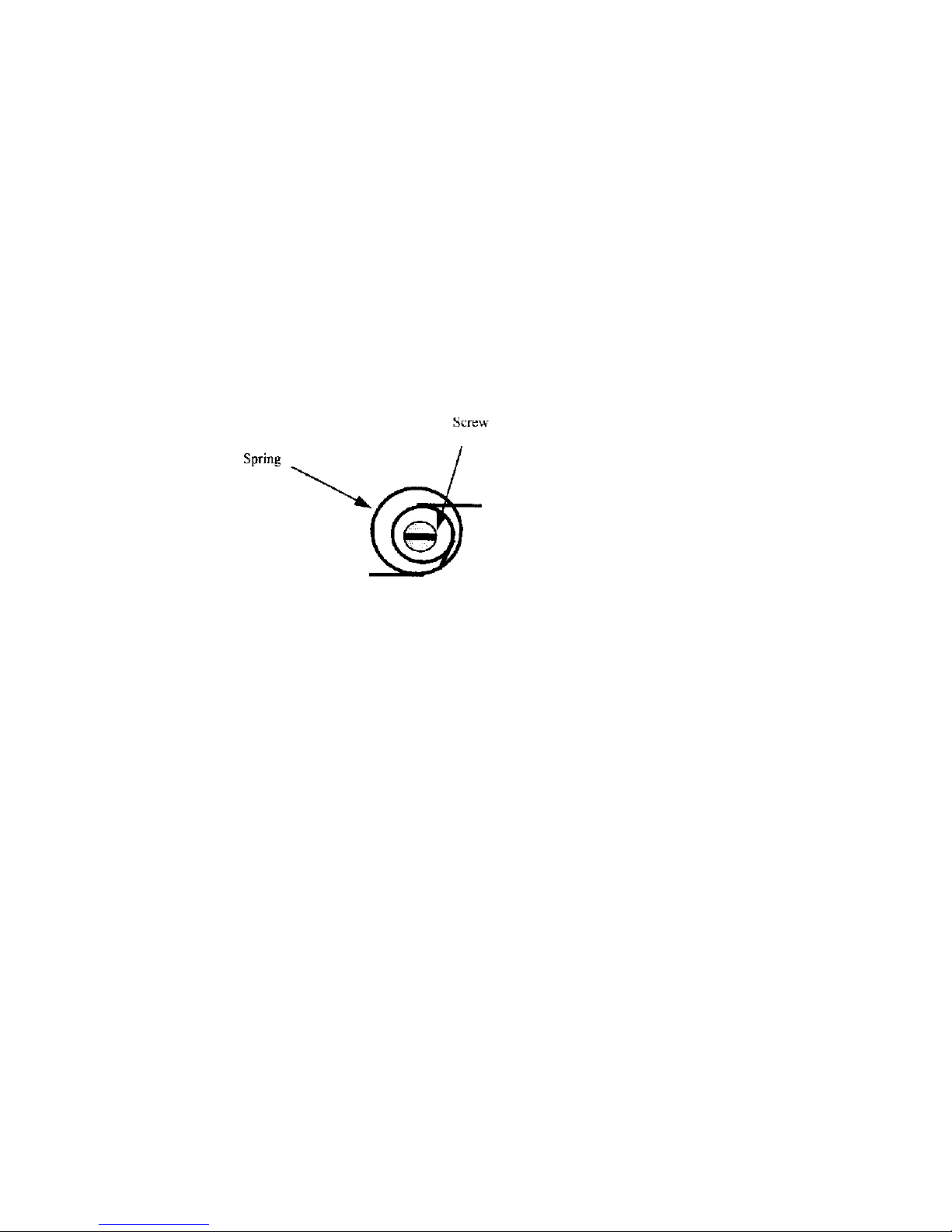
a. Remove rear cover by removing the 4 securing screws (rear 2 screws under visor
stoppers) and raise and support Drive Arm.
b. Using a thin bladed screwdriver, lever the spring from the hole in the bottom of the
pawl. Unscrew the slotted screw and remove slowly, being careful not to lose the
spacer.
c. Position the pawl so the spring is located in the hole at bottom of the pawl. Put the
screw into the pawl so that the screw comes into the middle of the spring levers, slide
the spacer onto the screw and
attach to the pawl arm
assembly, tighten the screw.
d. Carry out a functional check and if satisfactory replace rear cover.
5.2 Pawl Release Lever (Advance)
This lever is attached to the underside of the Long debris Blind Roller Support. 0µm and the
main arm is in the top position, the short lever holds the pawl away from the ratchet wheel.
This will leave a sufficient gap as to let the ratchet wheel rotate freely. Adjust the short lever
as required by moving the lever towards or away from the ratchet wheel at its pivot point.
5.3 Calibration
Calibration is set by selecting 2µm. One click from the pawl and ratchet wheel should be
heard.
Check by cutting wax sections so you can actually see the thickness change through micron
settings of 2, 4 & 6µm and that it is not cutting at zero thickness.
Page 19
M3500 Issue 2 - Feb 2006
Last reviewed: Oct 2010 / Next review Oct 2013
19
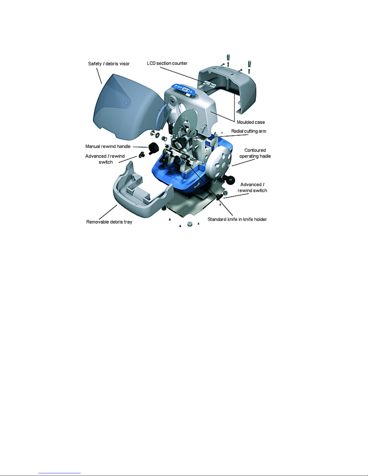
6 Exploded Diagram
Page 20
M3500 Issue 2 - Feb 2006
Last reviewed: Oct 2010 / Next review Oct 2013
20
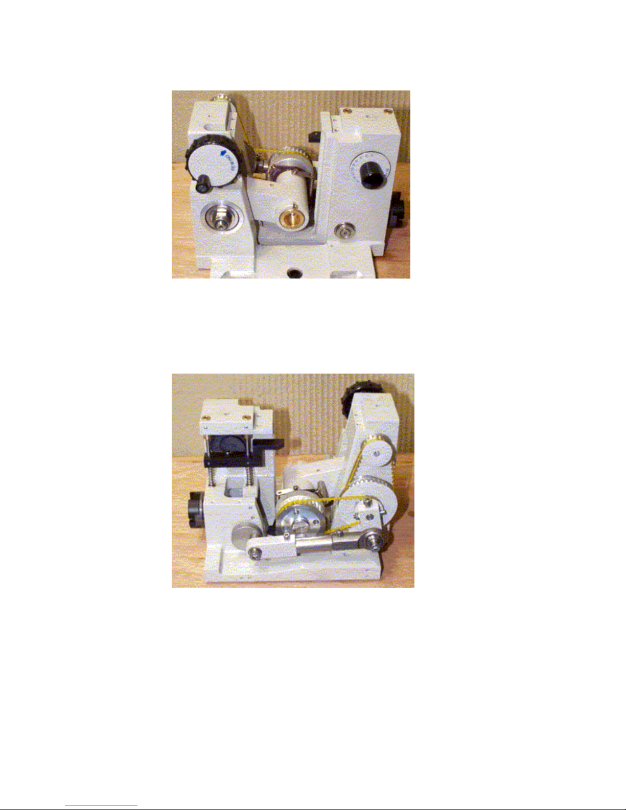
7. Internal Construction - Front
8. Internal Construction – Rear
Page 21

M3500 Issue 2 - Feb 2006
Last reviewed: Oct 2010 / Next review Oct 2013
21
9. SPECIFICATIONS
M3500 MICROTOME
Movement
●
Radial, flat cutting with retraction, manual hand wheel
operation
Cutting Stroke
●
57mm
Section thickness range
●
2µm to 30µm in 2µm increments (standard)
●
1µm to 15µm in 1µm increments (Special)
Total feed range
●
25mm at 0º knife tilt angle
Specimen holders
●
Quick release non-orientating holder (standard)
Other Notes:
●
Standard Knife
●
Disposable blades
●
Lever release Feather blade holder available on request
●
Manual & mortised advance/rewind facility
●
Height adjustable knife guards
●
Safety visor
DIMENSIONS
General
●
Overall height - 300mm
●
Overall width - 450mm
●
Overall depth - 440mm
Weight
●
<24Kgs
ELECTRICAL
Voltage
●
220-240v, 110-115v, 100v
●
50/60Hz
●
13amp
Batteries
●
2 x AA (for section counter)
Fuse
●
Motorised advance/rewind stepper
Page 22

M3500 Issue 2 - Feb 2006
Last reviewed: Oct 2010 / Next review Oct 2013
22
Accessories
Code Description
212-048 Standard vice clamp, can be fitted instead of quick
release cassette holder at no extra cost
212-049 Standard vice clamp with orientation
212-046 Cassette quick release holder
212-047 Cassette quick release holder with orientation
50230 Standard knife with box, C
profile
50724 Knife sharpening back for 50230
52671 Knife sharpening kit
57612 Coarse abrasive 6 grms net
57611 Fine abrasive 6grms net
57610 Honing compound 6grms net
50239 Clock oil 6grms net
57903 Lever release Feather blade holder
50241 Pack of 50 feather blades
138404-16 Spare fuses 1
amp(T)
52658 Vertical vice clamp
52632 Vertical vice clamp 45°
57713-1 Bright Cryospray 134, 300ml aerosol can
57713 Bright Cryospray 134, 300ml aerosol can, carton of 12 cans
57355 Low temperature grease, 5gms net
57344 Knife cleaning brush
Page 23

M3500 Issue 2 - Feb 2006
Last reviewed: Oct 2010 / Next review Oct 2013
23
MATERIAL SAFETY DATA SHEET
Name: CRYO-M-BED
Part Number: 53581
Product Information
By: Bright Instrument Company Limited
Address: St Margaret’s Way, Huntingdon, Cambs, PE29 6EU, England
Telephone: 01480 454 528 / 451 499 / 451 980
Emergency: 999
Fax: 01480 456 031
Email: [email protected]
Trade/Type: EMBEDDING COMPOUND
Container: Disposable plastic bottles
Uses: Embedding compound for frozen tissue
specimens
Data Sheet: 3
Description: Colourless viscous liquid
Information on Ingredients Physical and Chemical Properties
Blend of polyviol alcohol 217, thymol and water
Colourless viscous liquid
Hazards Identification: Stability and Reactivity
Skin: Can cause skin irritation May react with oxidising materials
Respiratory: May cause difficulty in breathing if
exposed to very high concentration
Ingest: May be harmful by ingestion
Eyes: Eye irritation
First Aid procedures Toxicoloigical Information
Skin: Wash thoroughly, with soap and
water
No harmful effects if handled correctly. May give off toxic
fumes in the case of fire
Respiratory: Move to fresh air
Ingest: Rinse mouth out with water, in
sever cases seek medical attention
Eyes: Flush copiously for at least 15
minutes
Fire Fighting Measures Ecological Information
Hazards: May cause toxic fumes Degradable, miscible in all proportions
Equipment: Water spray, foam, dry powder,
Co2
Accidental Release Measures Disposal Considerations
Spill: Absorb on an inert absorbent, bag
and arrange disposal. Wash area
in water and detergent
Waste: Bag and dispose of in accordance
with local authority requirements
Handling and Storage Transport Information
Special
Requirements:
NONE No restrictions
Exposure Controls Regulatory Information
OES: Not assigned (long term, 8 hour
TWA)
NONE
Skin: Avoid contact
Respiratory: Avoid very high concentrations
Ingest: Do not eat, drink or smoke
Eyes: Goggles should be worn
Additional Information/Comments:
Information given is, to the best of the Company’s knowledge and belief, accurate and reliable. However, no
warranty, guarantee or representation is made to it’s accuracy, reliability of completeness.
Issue 6 /June 2000 - Last reviewed: Sept 2010 / Next review: Sept 2012
Page 24

M3500 Issue 2 - Feb 2006
Last reviewed: Oct 2010 / Next review Oct 2013
24
MATERIAL SAFETY DATA SHEET
Name: CRYOSPRAY
Part Number: 57713
Product Information
By: Bright Instrument Company Limited
Address: St Margaret’s Way, Huntingdon, Cambs, PE29 6EU, England
Telephone: 01480 454 528 / 451 499 / 451 980
Emergency: 999
Fax: 01480 456 031
Email: [email protected]
Trade/Type: Bright Cryospray 134 Aerosol Freezing Agent
Container: Aerosol
Uses: Rapid Freezing of tissue specimens to –52ºC
Data Sheet: 48
Description: Colourless viscous liquid
Information on Ingredients Physical and Chemical Properties
1, 1, 1, 2 – Tetrafluoroethane – contents 80-100%
Appearance: Aerosol
Odour: Characteristic
Hazards Identification: Stability and Reactivity
May cause frost bite if intentionally misused Avoid powdered metal, alkali metals alkali earth metals
Avoid heat, flames and other sources of ignition
First Aid procedures Toxicoloigical Information
Skin: Wash thoroughly, with soap and water May cause frost bite if intentionally misused No harmful
effect if handled correctly. May give off toxic fumes in the
case of fire
Respiratory: Provide rest, warmth and fresh air If
discomfort continues, seek medical
attention
Ingest: Rinse mouth out with water, in sever
cases seek medical attention
Eyes: Flush copiously for at least 15 minutes
SEEK MEDICAL ADVICE
Fire Fighting Measures Ecological Information
This product is not classed as flammable under current
regulations. Special
Fire Fighting Procedures : use water to keep fire exposed
containers cool and disperse vapours. Breathing apparatus
should be worn if exposure of fumes s likely.
Unusual Fire Explosion Hazards: Possible risk of can
rupture when exposed to fire/high temperatures.
Hazardous Decomposition Products: Fire or high
temperatures create halogenated hydrocarbons, oxides of
carbon
Water Hazard Classification: Discharge of product will enter
the atmosphere and will not result I long term aqueous
contamination
Global Warming Potential: 0.28 (R11=1) (1,1,1,2 –
Tetrafluorethane) Ozone Depletion Potential 0 (R11=1)
(1,1,1,2 – Tetrafluorethane)
Accidental Release Measures Disposal Considerations
Spill: Let evaporate and ventilate area well Waste: DO NOT pierce or burn empty cans. Dispose
of in accordance with local authority
requirements.
Handling and Storage Transport Information
Usage Precautions: CAUTION pressurised container DO
NOT expose to temperatures exceeding 50ºC
DO NOT puncture or incinerate even when empty
DO NOT spray onto naked flame or any incandescent
material
Spray in short bursts to prevent cooling of the can
STORAGE PRECAUTIONS: Store in a cool dry place,
away from all sources of heat, including direct sunlight
Road: UN No.1950 CEFUC TEC (R) No.20G26-1 ADR
Class 2 ADR ITEM No.5A
Air: UN Air No.1950 Air Transport Class 2
Sea: UN Sea No.1950 Sea Transport Class No.2 IMDG
Page No.2102
Exposure Controls Regulatory Information
1,1,1,2 – Tetrafluoroethane (HFC 134a) OED: Long term
exp (8hours TWA ref period) 1000ppm (rec)/4240mg/m3
Skin: Avoid contact, it is advised to wear gloves
Respiratory: Good ventilation required if used in confined
space
Ingest: Do not eat, drink or smoke
Eyes: Wear goggles during use if there is any risk of eye
contact, but not generally required under normal use.
CHIP: S23 DO NOT breathe gas/fumes/vapour/spray
CHIP: S24/S25 Avoid contact with skin and eyes
CHIP: S51 use only in well ventilated areas
COSHH Regulations 1999
Additional Information/Comments:
Information given is, to the best of the Company’s knowledge and belief, accurate and reliable. However, no
warranty, guarantee or representation is made to it’s accuracy, reliability of completeness.
Issue 7 /Jan 2004 - Last reviewed: Sept 2010 /Next review: Sept 2012
Page 25
M3500 Issue 2 - Feb 2006
Last reviewed: Oct 2010 / Next review Oct 2013
25
MATERIAL SAFETY DATA SHEET
Name: Low temperature Grease
Part Number: 57355
Product Information
By: Bright Instrument Company Limited
Address: St Margaret’s Way, Huntingdon, Cambs, PE29 6EU, England
Telephone: 01480 454 528 / 451 499 / 451 980
Emergency: 999
Fax: 01480 456 031
Email: [email protected]
Trade/Type: OPTITEMP TTI
Container: Plastic Tube
Uses: For lubrication of microtomes and remote
control spindles
Data Sheet: 87
Description: Lubrication at arctic to high temperature
ranges
Information on Ingredients Physical and Chemical Properties
Lubricant grease based on synthetic oil
Physical form: Paste
Density: @20ºC, 965Kg/m3
Odour: Mild
Colour: Brown
Flashpoint: (closed) 215 (Mineral)
Water Solubility: Insoluble
Hazards Identification: Stability and Reactivity
This product is NOT classified as hazardous Stable: Yes will not polymerise
Conditions to Avoid: Temperatures above 215ºC
Materials to Avoid: Strong oxidising agents
Hazardous Decomposition/Combustion Products:
NONE with correct use.
First Aid procedures Toxicoloigical Information
Skin: Wash thoroughly, with soap and
water
Health effects:
EYES: May cause transient irritation.
SKIN: Unlikely to irritate on brief or occasional exposure
INHALATION: Low volatility make inhalation unlikely at
ambient temperatures.
INGESTION: May cause nausea, vomiting and diarrhoea
CHRONIC: Repeated and prolonged skin contact may
lead to skin disorders.
OTHER: NONE known
Respiratory: Remove from exposure
Ingest: DO NOT induce vomiting. Seek
medical advise immediately
Eyes: Flush copiously for at least 15
minutes. If irritation persists
SEEK MEDICAL ADVISE
Fire Fighting Measures Ecological Information
FIRE: Extinguish fires with foam, dry
powder, CO2 or water fog - do not
use water jets
When used and disposed of as intended, no adverse
environmental effects are foreseen
Accidental Release Measures Disposal Considerations
Spill: Avoid entry into drains and
waterways, spilt product will
present a slip hazard
Waste: Dispose of in accordance with local
authority requirements
Handling and Storage Transport Information
Handling:
Storage:
No special precautions
Store out of direct sunlight, do not
leave container unsealed
Not classified as dangerous to transport
Exposure Controls Regulatory Information
None of the ingredients of this product have an
occupational exposure limit
This product is a preparation and is NOT classified
according to EEC Guideline 88/379
Additional Information/Comments:
Information given is, to the best of the Company’s knowledge and belief, accurate and reliable. However, no
warranty, guarantee or representation is made to it’s accuracy, reliability of completeness.
Issue 2 /March 2000 - Last reviewed: Sept 2010 / Next review: Sep 2012
Page 26

M3500 Issue 2 - Feb 2006
Last reviewed: Oct 2010 / Next review Oct 2013
26
Knives / Blades
SAFETY WARNING
EXTREMELY SHARP KNIVES / BLADES
USE KNIFE / BLADE GUARDS AT ALL TIMES
USE CORRECT TOOLS FOR REMOVAL AND
INSERTION OF KNIVES / BLADES
DO NOT LEAVE KNIVES / BLADES LAYING
AROUND
PLACE KNIVES / BLADES NOT IN USE, INTO
BOX / WALLET PROVIDED
Page 27

M3500 Issue 2 - Feb 2006
Last reviewed: Oct 2010 / Next review Oct 2013
27
QA028/ISSUE5/OCT00(F003)
HEALTH AND SAFETY AT WORK ACT
DE
CO
NTAMINATION CERTIFICATE
Any product which is to be returned to Bright Instrument Company Limited or serviced on site,
must be cleaned and decontaminated in the appropriate manner. This certificate, duly
completed, must be either sent in advance (fixed to the outer packing containing the product),
or handed to the service engineer.
Packages will not be opened nor servicing commenced until the Company or service engineer have
received a satisfactory certificate. Should returned goods be considered a hazard by the Company, they
will be returned immediately to the customer at his/her expense. NB: Microtome knives must be in
boxes.
Description:
Product Code: Serial Number:
Order Number: Quantity:
Tick Box A if applicable. Otherwise complete all parts of B, providing further information as requested or
appropriate.
A
This equipment has not been in contact with unfixed biological samples.
B 1. This equipment has been exposed internally or externally to hazardous materials as indicated
below:
YES/NO Blood, body fluids, pathological samples Provide further details here:
YES/NO Other biohazards
YES/NO Chemicals/substances hazardous to health
YES/NO Other hazards
2. This equipment has been cleaned and decontaminated:
YES/NO If YES, give details of the methods:
Provide further details here:
If NO*, please indicate why not:
* Such equipment must not be returned without the written agreement of Bright Instrument Company Limited.
3. The equipment has been prepared to ensure safe handling/transportation.
YES/NO
Signed: Institute:
Department:
Address:
Name: Postcode:
Position: Telephone: Extn:
Date: Facsimile:
Page 28

M3500 Issue 2 - Feb 2006
Last reviewed: Oct 2010 / Next review Oct 2013
28
DECONTAMINATION PROCEDURES
Cryostats & Ultra Low Temperature Freezing Units
If decontamination is required carry out the standard procedures as practised in your
laboratory. It is the responsibility of the customer to use a decontamination procedure
appropriate to his/her work. The following decontamination method is as recommended in the
‘Code of Practise for the Prevention of Infection in Clinical Laboratories and Post-mortem
Rooms’, ISBN 0 11 320464 7.
1 Bring the cryostat to room temperature.
2 Place 50-100ml of formalin BP in a flat dish inside the chamber. Close the window.
3 Leave for at least 24 hours, preferably 48 hours.
4 Open the window and place a beaker containing 10ml of ammonia SG.880 in the chamber. Close
the window.
5 Leave for one hour. The cryostat is now decontaminated.
Microtomes
If decontamination is required carry out the standard procedures as practised in your
laboratory. It is the responsibility of the customer to use a decontamination procedure
appropriate to his/her work.
Microtome Knives
If decontamination is required carry out the standard procedures as practised in your laboratory. It is
the responsibility of the customer to use a decontamination procedure appropriate to his/her work.
For further information regarding alternative decontamination procedures please refer to ‘Safe
Working and the Prevention of Infection in Clinical Laboratories’, ISBN 0 11 885446 1.
Page 29

M3500 Issue 2 - Feb 2006
Last reviewed: Oct 2010 / Next review Oct 2013
29
QA023/ISSUE 4/AUG99(F018)
QUALITY SURVEY REPORT
Our watchword is QUALITY. In our continuing endeavour to improve the quality and performance of our
processes and products, we would welcome any initial comments on the following aspects of our service
and products. As you have only just received the product we do not feel that you could asses the actual
workings of the instrument accurately, so we will follow up in approximately six months with a Customer
Feedback – Voice of the Customer questionnaire. If, of course, you have any comments to make prior to
receiving the questionnaire, please feel free to contact us.
Please return this form either by post or by fax on 01480-456031, for the attention of the QA Manager.
Model: Serial Number:
Institute: Department:
Address:
Postcode:
Telephone: Extension:
Aspect Comments and Suggestions
Purchasing: Did the purchasing process
run smoothly with respect to our
involvement? e.g. correct advice, lead
times, payment arrangements etc.
Delivery: Was the instrument in a
satisfactory condition on arrival?
Installation: Did we install the
instrument? If so was adequate pre-use
instruction given?
User information: Did you receive an
operating manual? Do you believe it is
comprehensive enough for your use?
Safety: Any comments?
Miscellaneous: Any other aspect you
would like to comment on, e.g.
appearance, first impressions etc.
Signed:………………….…………….…. Name:………………………..….…..…….
Position:……….……….……………..…….
Thank you for helping us to help you in the future
Page 30
EMOTORCIM 0053M
YLBMESSA
040-212
RAER NO WEIV
EDISREDNU MORF
20 YAM
JJT
3 FO 1 THS
TNORF NO WEIV
THGIR POT MORF
ELDNAH EVIRD
DEVOMER
200-212 & 100-212 NO DESU TXEN YLBMESSA SIHT
SGNIWARD SIHT FO 3 & 2 STEEHS OT REFER SLIATED ROF
NWARD
DECART
DEKCEHCDEVORPPAETAD
EUSSI
NOITPIRCSED
TSIL STRAP EES -: LAIRETAM
NAELC -: HSINIF
2:1 ELACS
mm NI SNOISNEMID LLA
NOITCEJORP ELGNA dr3
.DTL .OC TNEMURTSNI THGIRB
ELTIT
.oN GNIWARD
DETATS SSELNU SECNARELOT
D'PPA
ETAD
JJT
1732 NC
3
50/9
DEVRESER STHGIR LLA - DETCETORP THGIRYPOC
! ELACS TON OD
!KSA - TBUOD NI FI
-: LAMICED
-: soN ELOHW
-: RALUGNA
01,0
05,0
5,0
-: SETON
.SEGDE DNA SRENROC PRAHS ,SRRUB LLA EVOMER .1
.EERF HCTARCS DNA NAELC EB OT SECAFRUS LLA .2
Page 31
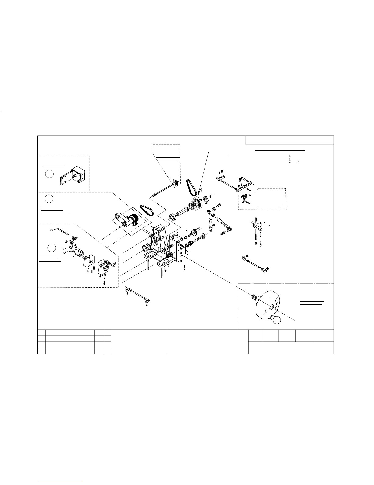
t
f
a
h
S
k
n
a
r
C
EMOTORCIM 0053M
YLBMESSA
e
v
i
r
D
t
u
p
n
I
)
l
e
e
h
w
d
n
a
H
(
tf
a
h
S
n
i
a
M
t
f
a
h
S
s
i
x
A
YLBMESSA-BUS EES
03325 oN TP OT
YLBMESSA -BUS EES
85915 oN TP OT
YLBMESSA-BUS EES
140-212 oN TP OT
YSSA BUS MRA NIAM
73915 oN TP EES
WEIV 'DEDOLPXE' ROF
YLBMESSA-BUS EES
160-212 oN TP OT
YLBMESSA -BUS EES
150-212 oN TP OT
TCARTER EES
YLBMESSA-BUS
450-212 oN TP OT
s
i
x
A
m
r
A
n
i
a
M
tf
a
h
S
n
i
a
M
s
i
x
A
t
f
a
h
S
n
i
a
M
t
f
a
h
S
w
e
R
/
v
d
A
w
e
R
/
v
d
A
t
f
a
h
S
040-212
JJT
20 YAM
3 FO 2 THS
GNIWARD SIHT FO 1 TEEHS EES YSSA TXEN ROF
SIHT NI SMETI FO SLIATED ROF
3 TEEHS EES AERA
SIHT NI SMETI FO SLIATED ROF
3 TEEHS EES AERA
SIHT NI SMETI FO SLIATED ROF
3 TEEHS EES AERA
51
21
96
86
76
07
27
4,11
3
4222 NC
JJT
50,5
JJT
4
0032 NC
60,3
JJT
1732 NC DEWEIVER
4
t
f
a
h
S
s
s
e
n
k
c
i
h
T
NWARD
DECART
DEKCEHCDEVORPPAETAD
EUSSI
NOITPIRCSED
TSIL STRAP TNEVELER EES -:LAIRETAM
NAELC -: HSINIF
5:1 ELACS
mm NI SNOISNEMID LLA
NOITCEJORP ELGNA dr3
.DTL .OC TNEMURTSNI THGIRB
ELTIT
.oN GNIWARD
DETATS SSELNU SECNARELOT
D'PPA
ETAD
DEVRESER STHGIR LLA - DETCETORP THGIRYPOC
! ELACS TON OD
!KSA - TBUOD NI FI
-: LAMICED
-: soN ELOHW
-: RALUGNA
01,0
05,0
5,0
-: SETON
.SEGDE DNA SRENROC PRAHS ,SRRUB LLA EVOMER .1
.EERF HCTARCS DNA NAELC EB OT SECAFRUS LLA .2
Page 32
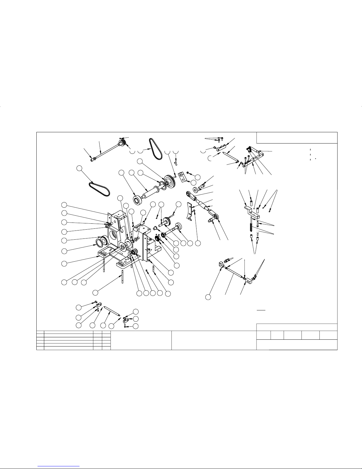
SNOITISOP EERHT NI
.EDIS HCAE
SNSOP 3 NI
SNSOP OWT NI
10502 & 9402 NC ,GNIWARD WEN
JJT
20,5
4
2
?
05
84
04
?
24
9405
04
?
81
11
9
22
01
21
12
81
25
04
64
74
?
24
?
04
64
74
1
01
11
5
6
4
06
16
65
?
?
13
72
03
75
45
8
03
92
82
15
85
73
95
918
55
54
33
44
3323
05
43
42
5383
42
73
63
62
52
34
93
24
04
14
34
72
35
35
06
36
46
26
40,11
JJT
.SON METI WEN HTIW NWD'R 4222 NC
2
41
72
50,5JJT
3
0032 NC
56
60,3
JJT
1732NC
4
NWARD
DECART
DEKCEHC
DEVORPPA
ETAD
.DTL .OC TNEMURTSNI THGIRB
JJT
3 FO 3 THS
EMOTORCIM 0053M
YLBMESSA
.oN GNIWARD
040-212
SETON
20.5.31
DEVRESER STHGIR LLA-DETCETORP THGIRYPOC
ELTIT
.SEHCTARCS MORF EERF DNA NAELC EB OT SECAFRUS LLA .1
.SEGDE PRAHS DNA SRENROC PRAHS ,SRRUB LLA EVOMER .2
.DETATS ESIWREHTO SSELNU SECNARELOT
LAMICED
.oN ELOHW
.RALUGNA
01,0
05,0
5,0
EUSSI
NOITPIRCSEDD'PPAETAD
!ELACS TON OD
!KSA - TBUOD NI FI
GWD SIHT F0 2 THS -:ON YSSA NO DESU TSRIF
TSIL STRAP EES :LAIRETAM
NAELC :HSINIF
5,2:1 ELACS
mm NI SNOISNEMID LLA
.NOITCEJORP ELGNA dr3
Page 33

Part List
ReferenceItem
ode
212-040 ** ASSEMBLY, M3500MICROTOME
Qt
y
-PL
11 M3500 BASE CASTING RETRACT 51901-1
12 M3500 REWIND SHAFT 212-445
13 THICKNESS DISC LABEL SET 212-811
24 3020 REWIND SHAFT BUSH 51951
15 3020 REWIND SHAFT COLLAR 51952
26 PTFE WASHER (REWIND) 52013
17 M3500 THICKNESS DIAL HUB 212-411
28 THICKNESS CAM BUSH 50818
1 in 519149 3020 MAIN SHAFT 51909
210 3020 OIL RETAINING RING 52210
211 TAPER ROLLER RACE 32004XA 51990
1 in 5191412 3020 REWIND PULLEY ASSEMBLY 51958
1 in 5191413 3020 DRIVE ARM 51910
114 3020 THICKNESS CAM 51938
115 3020 REWIND SHAFT PULLEY ASSY 52330
1 in 5191416 CLINICUT/ STARLET TAPER PIN 51911
1 in 5191417 M5 X 10 SKT CAP HD ST/ST 55105
218 3T5/255 TIMING BELT 56563
220 CAM PLATFORM BUSH 51945-2
221 CAM PLATFORM BUSH 51945-1
222 CAM PLATFORM SPRING 51993
623 M4 x 4 SOCKET GRUB SCREW BZP 55000
124 M3500 CRANKSHAFT 212-479
125 3020 INPUT DRIVE GEAR 51904
226 BALL RACE BEARING 50991
127 M3500 CRANKSHAFT CAM 212-474
128 M3500 CRANKSHAFT CONNECTING SCREW 212-463
2 in 5233429 M3500/3020 CON ROD END 52334
130 3500/3020 KNOCK OFF CAM 52011
131 3020 CAM PLATFORM 51943
232 CAM PLATFORM PILLAR 51944
433 M3 X 5 GRUB SCREW BZP 50947
134 BALL (5/32")ST/ST =(4MM) 50956
135 3020 DEBRIS ROLLER SUPPORT LH 52117
636 3020 DEBRIS ROLLER BEARING 52120
137 3020 DEBRIS ROLLER SUPPORT RH 52118
338 3020 DEBRIS BLIND ROLLER 51997
439 M3 x 10 SKT CAP HD ST/ST 55241
1 in 5190840 3020 CON ROD LINK 51907
141 M3500 DRIVE ARM SCREW 212-462
242 3020 DEBRIS ROLLER SUPPORT 3M 52119
243 M3 X 12 SKT CAP HD ST/ST 55120
Page 1 of 2
BRIGHT INSTRUMENT Co Ltd - COPYRIGHT PROTECTED - ALL RIGHTS RESERVED
ISSUE CHECKED APPROVED AUTHORISED DATE
3 TJJ DJS CN 2371 07/03/2006
Page 34

Part List Continued
ReferenceItem
ode
212-040 ** ASSEMBLY, M3500MICROTOME
Qt
y
-PL
145 3020 DEBRIS ROLLER SUPP LH 51996
146 3020 DEBRIS ROLLER SUPP RH 51995
547 M4 X 10 SKT CAP HD ST/ST 55100
1 in 5191448 M4 PLAIN WASHER ST/ST 55616
1 in 5191449 M4 HEX FULLNUT ST/ST 55514
250 M5 X 6 GRUB SCREW BZP 55006
151 E CLIP 5/16" BZP 56403
152 M3500 FRONT COVER RIGHT BRACKET 212-104
153 M3500 FRONT COVER LEFT BRACKET 212-105
654 M4 x 8 PAN HD POZI ST/ST 55239
155 PLUNGER BALL 6MM 51341
156 M3500 PAWL RELEASE KNOCK OFF PIN 212-450
257 M3500 LONG MICROTOME STUD 212-416
258 M3500 SHORT MICROTOME STUD 212-417
159 3020 DEBRIS BLIND SUPP PIN 51999
160 PAWL ARM EXTENSION SPRING 58274
161 DEBRIS BLIND EXTENSION SPRING 58275
162 OILITE TIE BUSH 50532
168 ** M3500, MOTOR REWIND ASSEMBLY 212-041
169 ** M3500, PAWL RELEASE ASSEMBLY 212-051
170 ** M3500 KNIFE BLOCK RETRACT ASSY 212-054
172 ** M3500, INPUT DRIVESHAFT
(HANDWHEEL) ASSEMBLY
212-061
Page 2 of 2
BRIGHT INSTRUMENT Co Ltd - COPYRIGHT PROTECTED - ALL RIGHTS RESERVED
ISSUE CHECKED APPROVED AUTHORISED DATE
3 TJJ DJS CN 2371 07/03/2006
Page 35
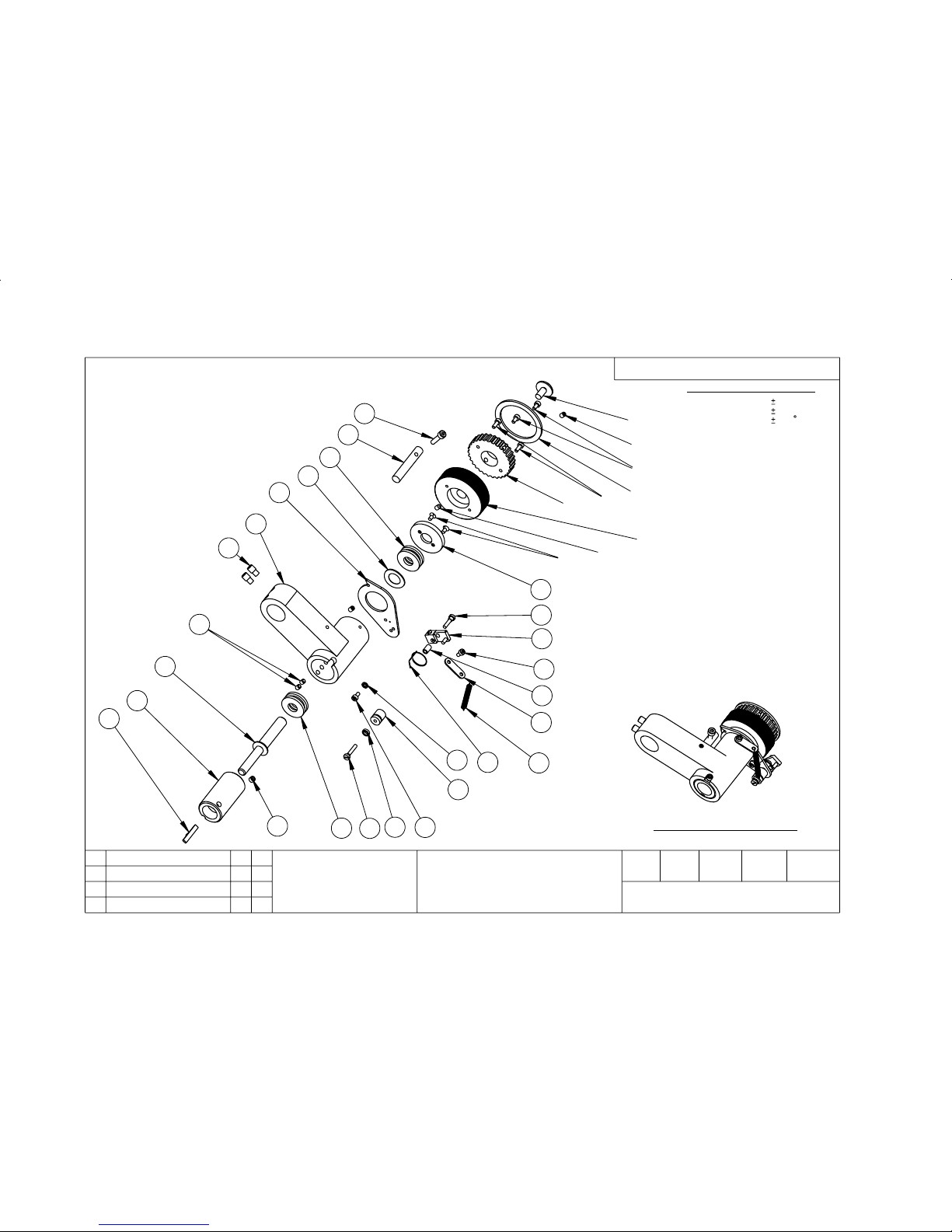
YLBMESSA MRA GNITTUC
0053M & 0203
73915
1
2
82
52
42
52
12
22
81
91
32
51
02
92
31
21
71
3
4
2
5
11
01
6
03
7
2
8
9
41
13
51
4.1732 NC
JJT
60,2
61
72
62
JJT
YLBMESSA MRA GNITTUC
6,3,6
NWARD
DECART
DEKCEHCDEVORPPAETAD
EUSSI
NOITPIRCSED
TSIL STRAP EES :LAIRETAM
NAELC :HSINIF
2:1 ELACS
mm NI SNOISNEMID LLA
NOITCEJORP ELGNA dr3
.DTL .OC TNEMURTSNI THGIRB
ELTIT
.oN GNIWARD
DETATS SSELNU SECNARELOT
D'PPAETAD
DEVRESER STHGIR LLA - DETCETORP THGIRYPOC
! ELACS TON OD
!KSA - TBUOD NI FI
-: SETON
.SEGDE DNA SRENROC PRAHS ,SRRUB LLA EVOMER .1
.EERF HCTARCS DNA NAELC EB OT SECAFRUS LLA .2
-: LAMICED
-: soN ELOHW
-: RALUGNA
01,0
05,0
5,0
Page 36

Part List
ReferenceItem
ode
51937 3020 MAIN ARM ASSEMBLY
Qt
y
-PL
** Use Assembly Drawing 51937 **
11 3020 RATCHET WHEEL SCREW 51923
42 M3 X 6 SOCKET CAP HEAD ST/ST 50952
1 3-11/21/313 3020 PAWL SCREW 51928
14 3020 PAWL PLASTIC 51927
15 3020 PAWL SPACER 51929
16 5040/5030 PAWL TENSION SPRING 50414
17 CLINICUT CAM ROLLER SPACER 51933
18 ANTI-ROLL MICRO BEARING 51270
19 3020 CAM ROLLER SCREW 51932
110 PAWL ARM SPRING 51992
111 3020 SPRING PLATE 51935
112 M3500/3020 LEADSCREW BODY 2 TO 30 51917
113 M3500/3020 LEADSCREW 2 TO 30 51918
114 3020 MAIN ARM KEY 52086
215 THRUST RACE SINGLE SKF 51100 51989
216 3020 MAIN ARM SCREW 51936
117 3020 MAIN ARM MACHINED 51916
118 M4 X 16 SKT CAP HD ST/ST 55104
119 3020 PAWL STOP PIN 51925
120 3020 PAWL ARM 51919
221 M3 X 6 CSK SLTD HEAD ST/ST 51550
122 3020 PAWL ARM RETAINER 51920
123 CRINKLE WASHER M12 51233
124 M3500 RATCHET WHEEL 212-432
325 M4 X 6 GRUB SCREW BZP 55001
126 M3500 RATCHET WHEEL PULLEY 212-433
127 3020 RATCHET PULLEY PLATE 51924
228 M3 x 8 SKT CAP HD ST/ST 55101
229 M4 X 5 SOCKET SET SCREWS ST/ST 55037
130 M3 PLAIN WASHER ST/ST MAX OD 7mm 55610
131 M5 X 5 GRUB SCREW BZP 50958
Page 1 of 1
BRIGHT INSTRUMENT Co Ltd - COPYRIGHT PROTECTED - ALL RIGHTS RESERVED
ISSUE CHECKED APPROVED AUTHORISED DATE
4 TJJ DJS CN 2371 06/03/2006
Page 37
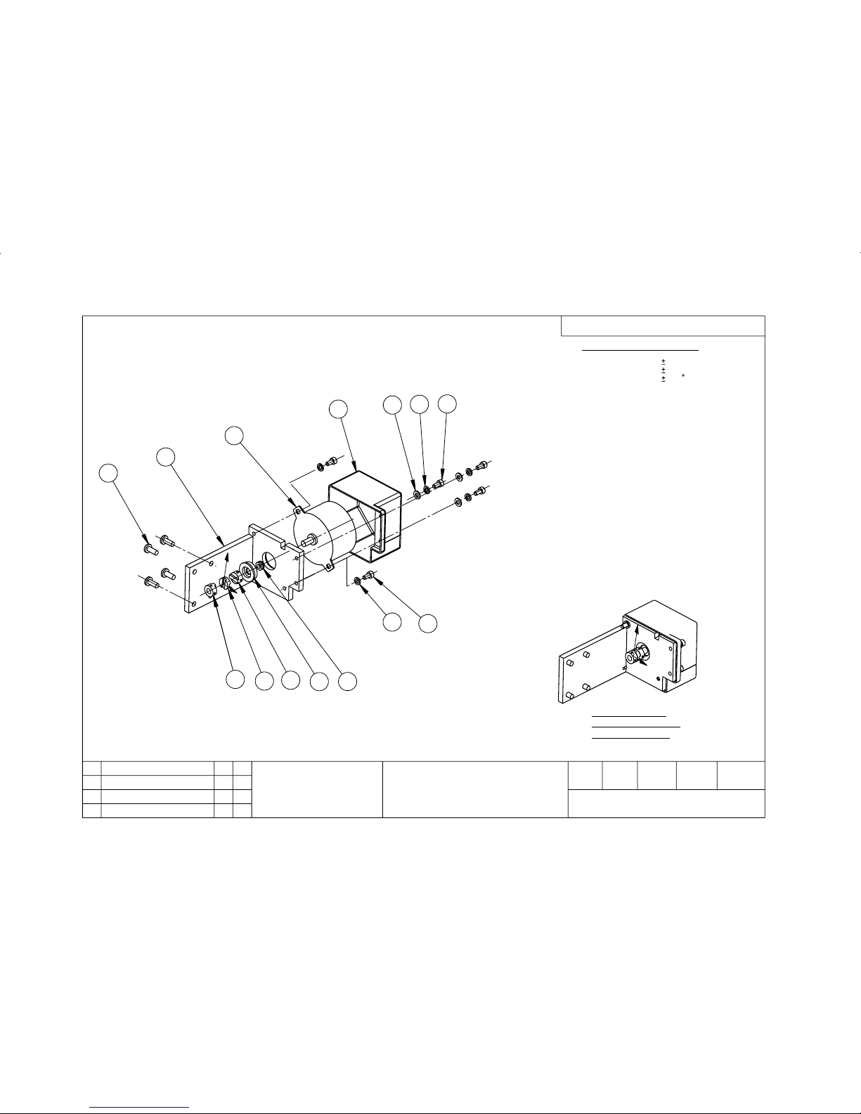
9
1
2
3
21
11
01
11
01
5
8
7
4
6
140-212
EMOTORCIM
DNIWER ROTOM
YLBMESSA BUS
JJT20/5/2
NWARD
DECART
DEKCEHCDEVORPPAETAD
EUSSI
NOITPIRCSED
TSIL STRAP EES -:LAIRETAM
NAELC :HSINIF
1:1 ELACS
mm NI SNOISNEMID LLA
NOITCEJORP ELGNA dr3
EMOTORCIM
DNIWER ROTOM
YLBMESSA-BUS
.DTL .OC TNEMURTSNI THGIRB
ELTIT
.oN GNIWARD
DETATS SSELNU SECNARELOT
D'PPA
ETAD
60,2
JJT
DOM1732 NC .
2
20,5
JJT
0502 NC .GRD WEN
1
DEVRESER STHGIR LLA - DETCETORP THGIRYPOC
! ELACS TON OD
!KSA - TBUOD NI FI
-: LAMICED
-: soN ELOHW
-: RALUGNA
01,0
05,0
5,0
-: SETON
.SEGDE DNA SRENROC PRAHS ,SRRUB LLA EVOMER .1
.EERF HCTARCS DNA NAELC EB OT SECAFRUS LLA .2
Page 38

Part List
ReferenceItem
ode
212-041 ** M3500, MOTOR REWIND ASSEMBLY
Qt
y
-PL
11 3020 MOTOR BRACKET 52534-1
12 STEPPER MOTOR ADV/REW 138103-01
13 M3500 / 3020 MOTOR REWIND COVER 52159
14 OLDHAM COUPLING 6.00MM BORE 50434-03
15 OLDHAM COUPLING NYLON DISC 50434-04
16 OLDHAM COUPLING 1/4" BORE 50434-01
17 V-RING SEAL V6A 52158
18 ** M3500 MOTOR LOCATOR 52550-1
49 M5 X 12 PAN HD POZI BZP 55219
510 M4 X 8 SKT CAP HD ST/ST 55033
511 M4 PLAIN WASHER ST/ST 55616
312 M4 NYLON WASHER 55633
Page 1 of 1
BRIGHT INSTRUMENT Co Ltd - COPYRIGHT PROTECTED - ALL RIGHTS RESERVED
ISSUE CHECKED APPROVED AUTHORISED DATE
1 TJJ DJS CN2371 17/02/2006
Page 39
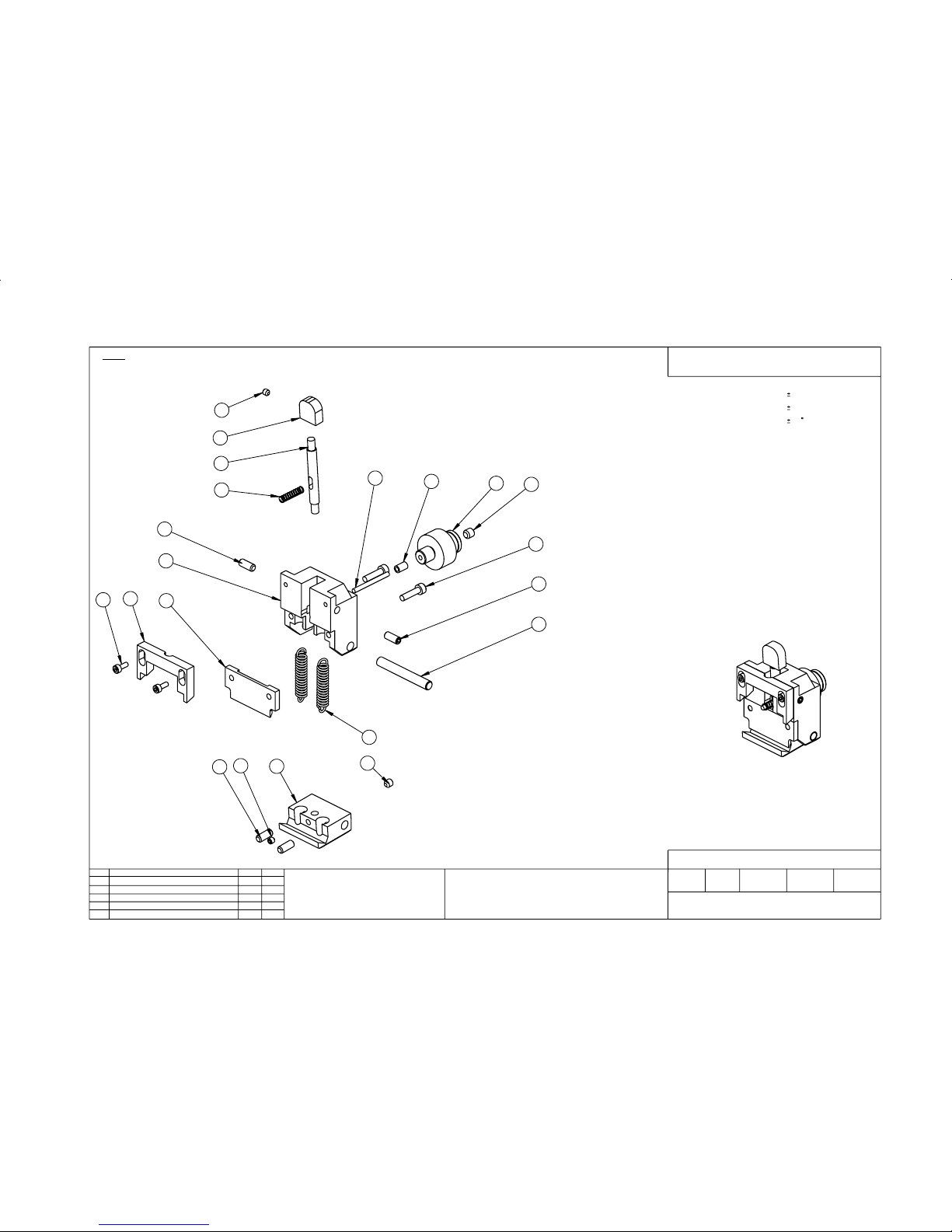
2
2
2
2
71
5
7
21
81
6
9
31
8
61
01
61
1
41
3
4
11
61
71
2
51
2
1732NC . NWARDERJJT
60,3
GNITATNEIRO -NON SRQC
YLBMESSA
GNITATNEIRO -NON SRQC
YLBMESSA
NWARD
DECARTDEKCEHC
DEVORPPA
ETAD
.DTL .OC TNEMURTSNI THGIRB
JJT
FO THS
.oN GNIWARD
640 - 212
SETON
20/01/82
DEVRESER STHGIR LLA-DETCETORP THGIRYPOC
ELTIT
.SEHCTARCS MORF EERF DNA NAELC EB OT SECAFRUS LLA .1
.SEGDE PRAHS DNA SRENROC PRAHS ,SRRUB LLA EVOMER .2
.DETATS ESIWREHTO SSELNU SECNARELOT
LAMICED
.oN ELOHW
.RALUGNA
01,0
05,0
5,0
EUSSI
NOITPIRCSEDD'PPAETAD
!ELACS TON OD
!KSA - TBUOD NI FI
-:ON YSSA NO DESU TSRIF LIATED SIHT
mm NI SNOISNEMID LLA
.NOITCEJORP ELGNA dr3
Page 40

Part List
ReferenceItem
ode
212-046 M3500 HOLDER CASSETTE QUICK RELEASE
Qt
y
-PL
11 M3500 CQRS BODY 212-434
12 M3500 CQRS LOWER CLAMP 212-435
13 M3500 CQRS UPPER CLAMP 212-436
14 M3500 CQRS SUPPORT CLAMP 212-437
15 M3500 CQRS KNOB 212-438
16 M3500 CQRS NON ORIENTATING ADAPTOR 212-439
17 M3500 CQRS HANDLE 212-440
18 M3500 CQRS RELEASE PIN 212-441
19 M3500 CQRS RELEASE PIN SLEEVE 212-442
110 CQRS RETAINING PIN 50697
211 SPRING FOR CQRS 52657
112 M3500 COMPRESSION SPRING CQRS 58173
213 M4 X 16 SKT CAP HD ST/ST 55104
214 M3 x 8 SKT CAP HD ST/ST 55101
115 M5 X 5 GRUB SCREW BZP 55004
416 M5 X 12 GRUB SCREW BZP 55007
217 M4 x 4 SOCKET GRUB SCREW BZP 55000
118 M6 X 6 GRUB SCREW BZP 55008
Page 1 of 1
BRIGHT INSTRUMENT Co Ltd - COPYRIGHT PROTECTED - ALL RIGHTS RESERVED
ISSUE CHECKED APPROVED AUTHORISED DATE
2 TJJ DJS CN2371 07/03/2006
Page 41
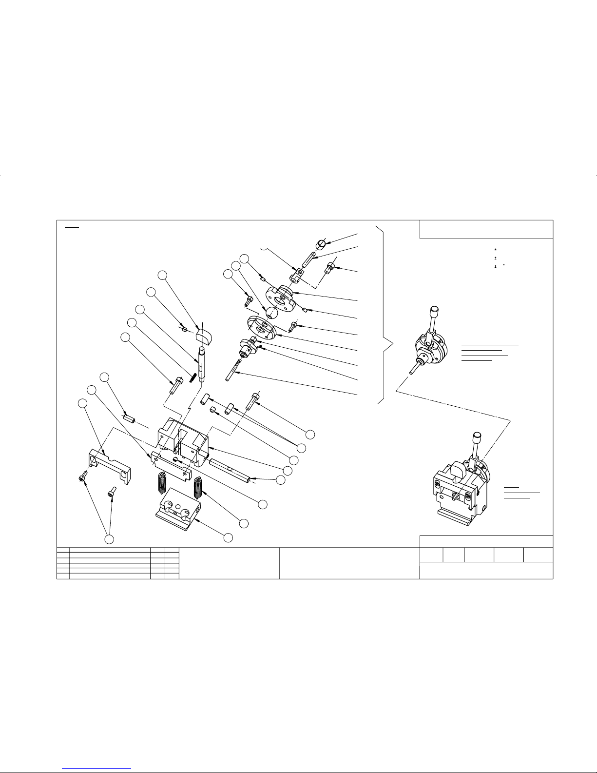
SNSOP 2 NI
SNSOP 2 NI
42
12
22
32
8
52
52
51
51
9
62
11
01
5
81
6
71
41
61
71
41
1
21
3
51
2
31
4
02
7
81
PMALC GNITATNEIRO
- YLBMESSA BUS
REBMUN TRAP OT
100-740-212
1
0502NC .GNIWARD WEN
YLBMESSA DAEH GNITATNEIRO SRQC
0053M
SRQC
GNITATNEIRO
YLBMESSA
JJT
20,01
NWARD
DECARTDEKCEHC
DEVORPPA
ETAD
.DTL .OC TNEMURTSNI THGIRB
JJT
FO THS
.oN GNIWARD
740 - 212
SETON
20/01/82
DEVRESER STHGIR LLA-DETCETORP THGIRYPOC
ELTIT
.SEHCTARCS MORF EERF DNA NAELC EB OT SECAFRUS LLA .1
.SEGDE PRAHS DNA SRENROC PRAHS ,SRRUB LLA EVOMER .2
.DETATS ESIWREHTO SSELNU SECNARELOT
LAMICED
.oN ELOHW
.RALUGNA
01,0
05,0
5,0
EUSSI
NOITPIRCSEDD'PPAETAD
!ELACS TON OD
!KSA - TBUOD NI FI
-:ON YSSA NO DESU TSRIF LIATED SIHT
TSIL STRAP EES :LAIRETAM
NAELC : HSINIF
1:1 ELACS
mm NI SNOISNEMID LLA
.NOITCEJORP ELGNA dr3
Page 42

Part List
ReferenceItem
ode
212-047 M3500 QUICK RELEASE CASETTE
Qt
y
-PL
11 M3500 CQRS BODY 212-434
12 M3500 CQRS LOWER CLAMP 212-435
13 M3500 CQRS UPPER CLAMP 212-436
14 M3500 CQRS SUPPORT CLAMP 212-437
15 M3500 CQRS KNOB 212-438
16 M3500 CQRS HANDLE 212-440
17 COMPRESSION SPRING M3500 58175
18 M3500 ORIENTATING HEAD REAR CLAMP 212-456
19 M3500 ORIENTATING HEAD FRONT CLAMP 212-457
110 M3500 CQRS ORIENTATING RELEASE PIN 212-460
111 M3500 CQRS ORIENTATING ADAPTOR 212-459
112 CQRS RETAINING PIN 50697
213 SPRING FOR CQRS 52657
214 M4 X 16 SKT CAP HD ST/ST 55104
415 M3 x 8 SKT CAP HD ST/ST 55101
116 M5 X 5 GRUB SCREW BZP 55004
417 M5 X 12 GRUB SCREW BZP 55007
218 M4 x 4 SOCKET GRUB SCREW BZP 55000
120 ORIENT OBJECT HOLDER BALL 51983
121 ORIENT OH LOCK LEVER 52097
122 3020 ORIENT OH LOCK SCREW 52261
123 3020 ORIENT OH LOCK 52260
124 3020 ORIENT OH LOCK KNOB 52098
225 M3 X 5 GRUB SCREW BZP 50947
126 1/16 X 1/4 SPRINGPIN ST/ST 55904
Page 1 of 1
BRIGHT INSTRUMENT Co Ltd - COPYRIGHT PROTECTED - ALL RIGHTS RESERVED
ISSUE CHECKED APPROVED AUTHORISED DATE
2 TJJ DJS CN2371 07/03/2006
Page 43
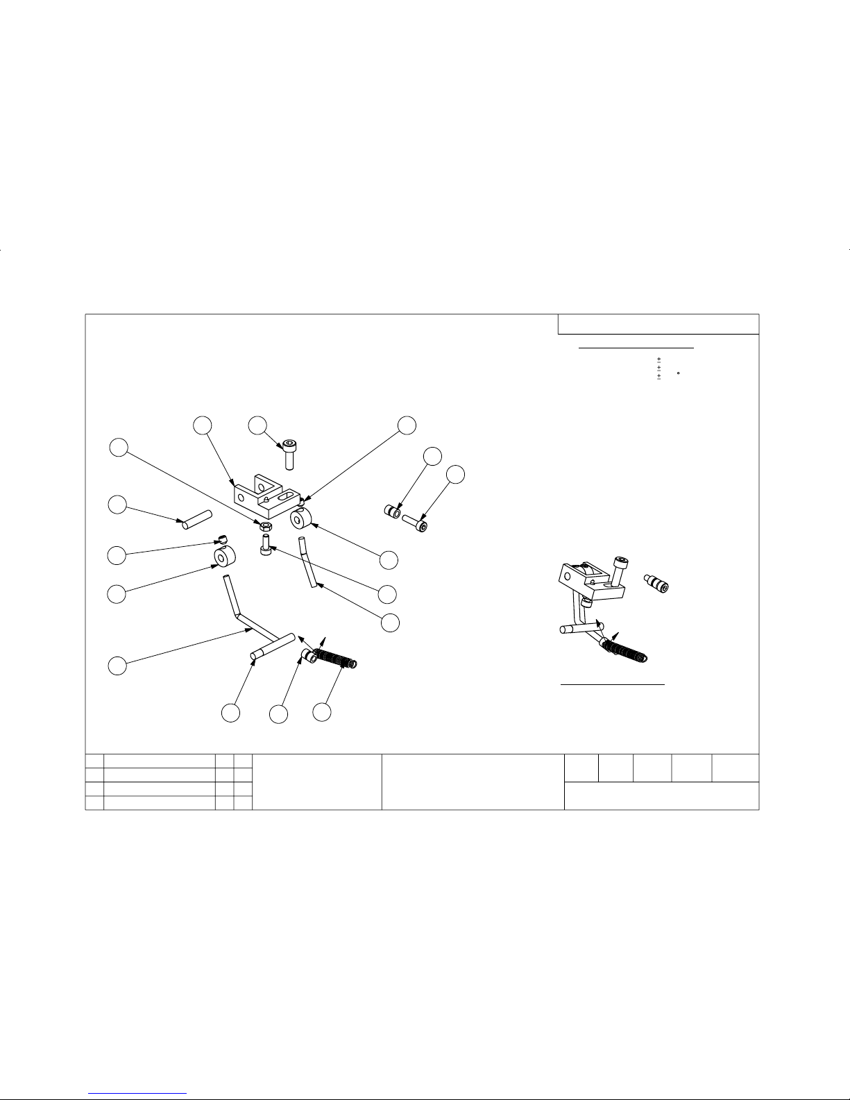
5
19
11
7
2
6
8
11
7
31
21
3
01
4
6
YSSA ESAELER LWAP
150 - 212
YSSA ESAELER LWAP
1
0502 NC ,EUSSI WENJJT
20/01
20/5
JJT
20/5
JJT
NWARD
DECART
DEKCEHCDEVORPPAETAD
EUSSI
NOITPIRCSED
TSIL STRAP EES -:LAIRETAM
NAELC -:HSINIF
1:1 ELACS
mm NI SNOISNEMID LLA
NOITCEJORP ELGNA dr3
.DTL .OC TNEMURTSNI THGIRB
ELTIT
.oN GNIWARD
DETATS SSELNU SECNARELOT
D'PPA
ETAD
DEVRESER STHGIR LLA - DETCETORP THGIRYPOC
! ELACS TON OD
!KSA - TBUOD NI FI
-: LAMICED
-: soN ELOHW
-: RALUGNA
01,0
05,0
5,0
-: SETON
.SEGDE DNA SRENROC PRAHS ,SRRUB LLA EVOMER .1
.EERF HCTARCS DNA NAELC EB OT SECAFRUS LLA .2
Page 44

Part List
ReferenceItem
ode
212-051 ** M3500, PAWL RELEASE ASSEMBLY
Qt
y
-PL
11 M3500 PAWL RELEASE BRACKET 212-447
12 M3500 PAWL RELEASE LEVER LONG 212-448
13 M3500 PAWL RELEASE LEVER SHORT 212-449
14 M3500 PAWL RELEASE KNOCK OFF PIN 212-450
15 M3500 PAWL RELEASE PIVOT PIN 212-451
26 M3500 PAWL RELEASE SPRING HOLDER 212-452
27 M3500 PAWL RELEASE LEVER BOSS 212-453
18 PAWL ARM SPRING 51992
19 M4 X 12 SKT CAP HD BZP 55103
110 M3 X 12 SKT CAP HD ST/ST 55120
211 M4 x 4 SOCKET GRUB SCREW BZP 55000
112 M3 x 8 SKT CAP HD ST/ST 55101
113 M3 FULL NUT ST/ST 50942
Page 1 of 1
BRIGHT INSTRUMENT Co Ltd - COPYRIGHT PROTECTED - ALL RIGHTS RESERVED
ISSUE CHECKED APPROVED AUTHORISED DATE
1 TJJ DJS CN2371 20/02/2006
Page 45
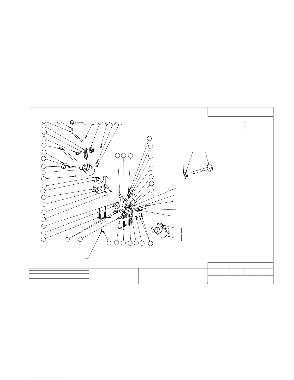
2
2
4
2
2
KCOLB EFINK 0203 / 0053 M
LEDOM TCARTER
YLBMESSA - BUS
NI NWOHS SA 2
SNOITISOP 2
SNOITISOP 2
NWOHS SA 2
SNSOP 2 NI
SNOITISOP 2
2
3
4
32
91
42
11
12
02
21
01
9
6
81
62
2
61
5
7
71
71
8
4
22
42
52
41
31
32
91
42
9
MORF DNA HTAENEB MORF NWOHS SI YLBMESSA
.TINU FO RAER EHT
1 METI DENIHCAM ) ESAB EMOTORCIM ( GNITSAC NIAM EHT
.YTIRALC NI TSISSA OT DETTIMO NEEB SAH TSIL STRAP FO
7
8
84
83
82
13
03
64
92
73
63
23
43
53
54
44
33
14
34
24
72
51
74
DETCURTSNOC ,ESIWREHTO
EDIS HR REP SA
94
SIHT DERIUQER METI
DNAH THGIR NI
YLNO KCOLB EFINK
1
4
8732 NC .DEIFIDOM
JJT
60,4
20,01
3602 NC .GNIWARD WEN
JJT
3
2332 NC & 0332 NC .DEIFIDOM
JJT
50.90
2
4922 NC .DEIFIDOM
JJT
50.50
TSIL STRAP EES :LAIRETAM
NAELC :HSINIF
1:1 ELACS
NWARD
DECART
DEKCEHC
DEVORPPA
ETAD
.DTL .OC TNEMURTSNI THGIRB
JJT
FO THS
.oN GNIWARD
450 - 212
SETON
20,01,9
DEVRESER STHGIR LLA-DETCETORP THGIRYPOC
ELTIT
.SEHCTARCS MORF EERF DNA NAELC EB OT SECAFRUS LLA .1
.SEGDE PRAHS DNA SRENROC PRAHS ,SRRUB LLA EVOMER .2
.DETATS ESIWREHTO SSELNU SECNARELOT
LAMICED
.oN ELOHW
.RALUGNA
01,0
05,0
5,0
EUSSI
NOITPIRCSEDD'PPAETAD
!ELACS TON OD
!KSA - TBUOD NI FI
-:ON YSSA NO DESU TSRIF LIATED SIHT
mm NI SNOISNEMID LLA
.NOITCEJORP ELGNA dr3
Page 46

Part List
ReferenceItem
ode
212-054 ** M3500 KNIFE BLOCK RETRACT ASSY
Qt
y
-PL
11 M3500 BASE CASTING RETRACT 51901-1
12 M3500 KNIFE BLOCK LH RETRACT 212-466
13 M3500 KNIFE BLOCK RH RETRACT 212-467
24 M3500 PIVOT BAR KNIFE BLOCK RETRACT 212-468
15 M3500 KNIFE BLOCK RETRACT LEVER LH 212-469
16 M3500 KNIFE BLOCK RETRACT LEVER RH 212-470
27 M3500 CONNECT ROD HOLDER 212-471
28 M3500 ADJUSTER SCREW PAD 212-472
29 ** M4 X 8 PTD GRUB SCREW BZP 55002-1
110 M3500 KNIFE BLOCK RETRACT PUSH ROD
PAD
212-481
111 M3500 PUSH ROD 212-482
112 M3500 PUSH ROD LOCATION PIN 212-473
113 M3500 CRANKSHAFT 212-479
114 M3500 CRANKSHAFT CAM 212-474
415 M3500 SPRING HOLDER 212-475
116 M3500 CONNECT ROD 212-476
217 M3500 OILITE BUSH 212-477
118 M3500 CONNECT ROD SUPPORT 212-478
419 TENSION SPRING 58135
120 MICRO BEARING DOUBLE SHIELDED 50940
121 ST/ST DOWEL PIN 2.5mm x 8mm 50489-1
422 M3 X 12 SKT CAP HD ST/ST 55120
423 M4 X 10 SKT CAP HD ST/ST 55100
624 M4 X 12 GRUB SCREW BZP 55003
225 M4 x 4 SOCKET GRUB SCREW BZP 55000
226 M4 x 6 SOCKET HEAD C/SUNK ST/ST 55030
127 3020 KNIFE CLAMP LH 52234
128 3020 KNIFE CLAMP RH 52235
129 TIE BAR 50442
230 5040/3020 KNIFE CLAMP SCREW 52195
231 LOCKING KEY KNOB 53779
132 M3500 WAX KNIFE GUARD BRACKET RH 212-426
233 M3500 WAX KNIFE GUARD HOLDER 212-428
234 M3500 KNIFE GUARD ROD 212-429
235 M3500 KNIFE GUARD HANDLE 212-430
236 M3500 KNIFE GUARD STUD 212-431
237 M4 KNOB 51542
238 M5 X 5 GRUB SCREW BZP 50958
241 PLUNGER BALL 4mm 51443
242 M3 X 6 CSK SLTD HEAD ST/ST 51550
243 M3 X 6 SOCKET CAP HEAD ST/ST 50952
Page 1 of 2
BRIGHT INSTRUMENT Co Ltd - COPYRIGHT PROTECTED - ALL RIGHTS RESERVED
ISSUE CHECKED APPROVED AUTHORISED DATE
4 TJJ DJS CN2378 08/05/2006
Page 47

Part List Continued
ReferenceItem
ode
212-054 ** M3500 KNIFE BLOCK RETRACT ASSY
Qt
y
-PL
244 005X1/8 HAMMER DRIVE BRASS 56100
245 3020 KNIFE GUARD KNOB 52244
246 M6 x ID F/R COILTHREAD WIRE INSERT 55005
147 M3500 WAX KNIFE GUARD BRACKET L H 212-427
148 5040 KNIFE BLOCK POINTER 50526
149 PLUNGER BALL 6MM 51341
Page 2 of 2
BRIGHT INSTRUMENT Co Ltd - COPYRIGHT PROTECTED - ALL RIGHTS RESERVED
ISSUE CHECKED APPROVED AUTHORISED DATE
4 TJJ DJS CN2378 08/05/2006
Page 48
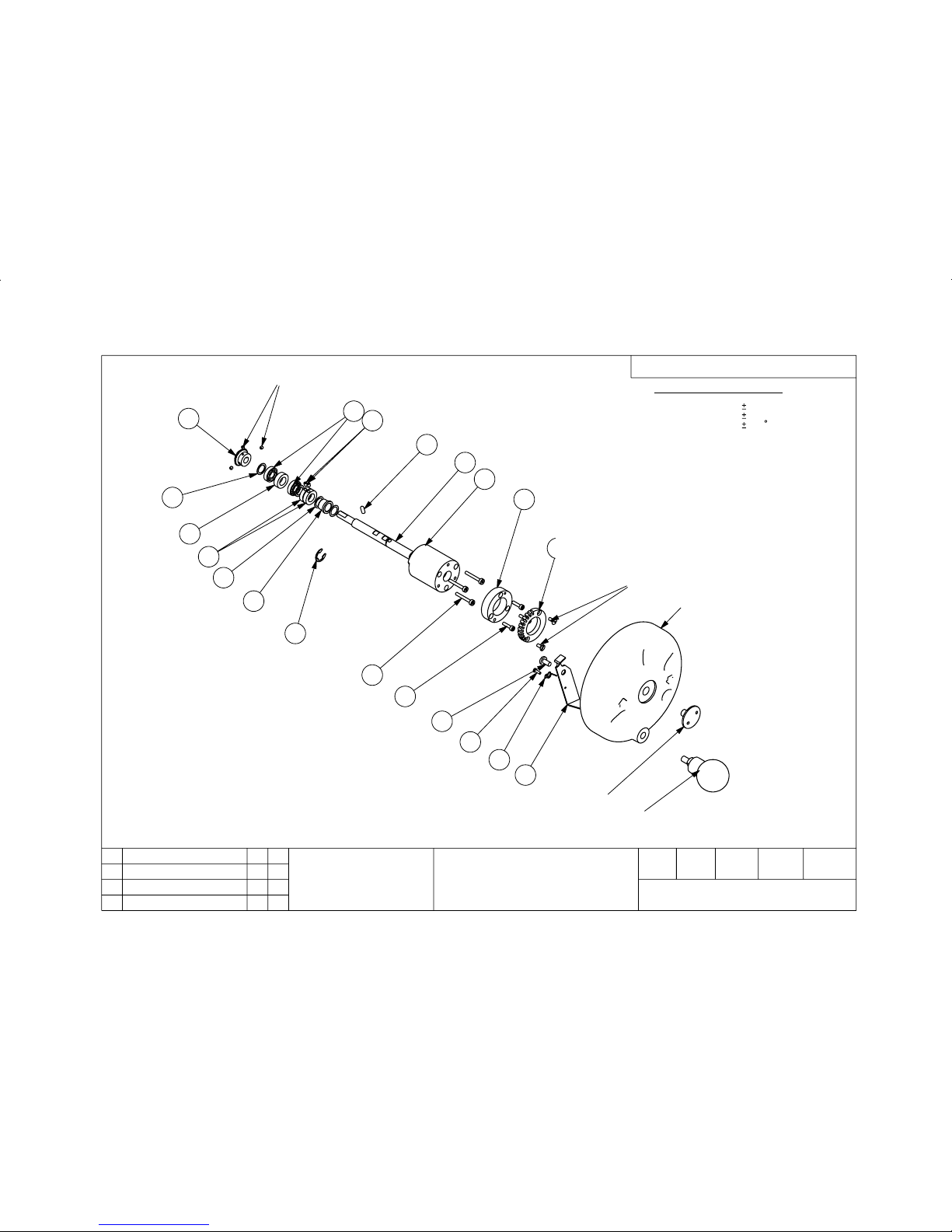
TFAHS EVIRD TUPNI
YSSA )LEEHWDNAH(
0053M
3
3
3
2
2
160-212
42
32
12
22
02
52
81
41
61
51
8
9
21
11
62
31
3
4
2
1
7
6
5
JJT
2/5/2
-: SETON
.SEGDE DNA SRENROC PRAHS ,SRRUB LLA EVOMER .1
.EERF HCTARCS DNA NAELC EB OT SECAFRUS LLA .2
.YSSA LANIF TA DETTIF EB YAM EVISULCNI NEVES OT 1 SMETI .3
EB OT DEEN LLIW SMETI ESEHT , REILRAE DETTIF FI
REVOC GNINOITISOP RETFA DETTIFER DNA DETNUOMSID
91
1
2,5,2
JJT
0502 NC
71
NWARD
DECART
DEKCEHCDEVORPPAETAD
EUSSI
NOITPIRCSED
TSIL STRAP EES : LAIRETAM
NAELC : HSINIF
2:1 ELACS
mm NI SNOISNEMID LLA
NOITCEJORP ELGNA dr3
.DTL .OC TNEMURTSNI THGIRB
ELTIT
.oN GNIWARD
DETATS SSELNU SECNARELOT
D'PPA
ETAD
DEVRESER STHGIR LLA - DETCETORP THGIRYPOC
! ELACS TON OD
!KSA - TBUOD NI FI
-: LAMICED
-: soN ELOHW
-: RALUGNA
01,0
05,0
5,0
Page 49

Part List
ReferenceItem
ode
212-061 ** M3500, INPUT DRIVESHAFT (HANDWHEEL)
ASSEMBLY
Qt
y
-PL
11 M3500/OTF5000 H/ WHEEL CASTING 212-403
12 HANDWHEEL TRIGGER 50033
13 M6 X 12 ROOFING BOLT BZP 55701
14 M3 x 10 PAN POZI ST/ST 55240
15 HANDWHEEL TRIGGER SPRING 50530
16 BALL GRIP P111/47+X-M10 52252
17 M3500/OTF5000 HANDWHEEL SCREW 212-413
18 M3500 HANDWHEEL BUSH HOLDER 212-423
19 M3500 STOP RING HOLDER 212-422
110 STOP RING 50622
311 M4 X 30 SOCKET CAP HEAD ST/ST 55099
312 M4 X 16 SKT CAP HD ST/ST 55104
213 M4 X 10 CSK HD SLTD BZP 55212
114 M3500 HANDWHEEL SHAFT 212-421
115 PEG TOP SHAFT CUTTING HANDWHEEL 50593
116 E CLIP 1/2" BZP 56402
217 PTFE WASHER 3/8" 3020 52083
118 5040 DRIVE SPINDLE BUSH 51058
219 PTFE WASHER DRIVE 1/2" 52014
220 M3500 HANDWHEEL SHAFT SPACER 212-424
221 BALL RACE BEARING 50991
122 3020 BEARING SPACER 51903
123 3020 INPUT DRIVE GEAR 51904
324 M4 x 4 SOCKET GRUB SCREW BZP 55000
225 M4 X 6 GRUB SCREW BZP 55001
Page 1 of 1
BRIGHT INSTRUMENT Co Ltd - COPYRIGHT PROTECTED - ALL RIGHTS RESERVED
ISSUE CHECKED APPROVED AUTHORISED DATE
3 TJJ DJS CN2371 20/02/2006
 Loading...