

Page 1
sv
en
Not for
Reproduction
Operator’s Manual
da
de
el
es
fi
fr
it
nl
no
pt
Betjeningsvejledning
Bedienungsanleitung
Εγχειρίδιο χρήσης
Manual del operario
Käyttöohjekirja
Manuel d’utilisation
Manuale per l’operatore
Gebruikershandleiding
Brukerens veiledning
Manual do Operador
Handbok
Copyright © 2017 Briggs & Stratton Corporation
Milwaukee, WI, USA. All rights reserved.
80026888WST
Revision A
Page 2
1
Not for
Reproduction
A
M
L
K
J
I
H
B
C
2
G
F
C
B
A
A
D
E
32
C
A
B
www.snapper.com2
Page 3
4
Not for
Reproduction
8
5
A
B
9
A
B
A
A
6
7
A
B
10
11
A
A
A
B
3
Page 4
12
Not for
Reproduction
15
A
B
A
13
14
B
A
B
16
B
A
17
A
A
www.snapper.com4
Page 5
18
Not for
Reproduction
2322
A
E
B
19
20
C
G
A
B
C
C
B
A
A
23
A
C
A
D
F
D
B
E
C
21
24
B
A
A
5
Page 6
25
Not for
Reproduction
26
29
C
B
A
30
A
B
A
27
28
A
A
A
31
B
A
www.snapper.com6
Page 7
32
Not for
Reproduction
35
C
C
E
33
A
B
B
A
C
36
E
C
B
D
D
A
A
B
34
X
C
D
A
X-1/8”
B
37
A
B
C
7
Page 8
38
Not for
Reproduction
39
41
D
C
A
B
B
A
42
B
40
B
A
A
B
A
C
Page 9

Thank You for purchasing this quality-built Snapper®
Not for
Reproduction
product. We’re pleased that you placed your confidence
in the Snapper brand. When operated and maintained
according to the instructions in this manual, your Snapper
product will provide many years of dependable service.
Products Covered by this Manual
2691382-00
2691383-00
This manual contains safety information to make you
aware of the hazards and risks associated with the
machine and how to avoid them. This machine is designed
and intended only for finish cutting of established lawns
and is not intended for any other purpose. It is important
that you read and understand these instructions thoroughly
before attempting to start or operate this equipment. Save
these original instructions for future reference.
The Illustrated Parts List for this machine can be downloaded from www.snapper.com. Please provide model
and serial number when ordering replacement parts.
Date of Purchase________________________________
Retailer________________________________________
Retailer’s Phone Number__________________________
Equipment
Model Number____________________________
Serial Number____________________________
Table of Contents
Operator Safety .......................................................... 10
Features and Controls ............................................... 15
Operation ....................................................................15
Maintenance ...............................................................18
Safety Interlock Systems Check .............................. 21
Troubleshooting ......................................................... 26
Warranty ......................................................................28
Specifications ............................................................. 30
Engine
Model__________________________________
Type___________________________________
Code___________________________________
en
9
Page 10
Operator Safety
Not for
Reproduction
WARNING: This powerful cutting machine is capable of amputating hands and feet and can throw objects
!
that can cause injury and damage! Failure to comply with the following SAFETY instructions could result
in serious injury or death to the operator or other persons. The owner of the machine must understand
these instructions and must allow only persons who understand these instructions to operate machine.
Each person operating the machine must be of sound mind and body and must not be under the influence
of any substance, which might impair vision, dexterity or judgment.
WARNING
POISONOUS GAS HAZARD. Engine exhaust contains carbon
monoxide, a poisonous gas that could kill you in minutes. You
CANNOT see it, smell it, or taste it. Even if you do not smell exhaust
fumes, you could still be exposed to carbon monoxide gas. If you
start to feel sick, dizzy, or weak while using this product, shut it
off and get to fresh air RIGHT AWAY. See a doctor. You may have
carbon monoxide poisoning.
• Operate this product ONLY outside far away from windows, doors and vents
to reduce the risk of carbon monoxide gas from accumulating and potentially
being drawn towards occupied spaces.
• Install battery-operated carbon monoxide alarms or plug-in carbon monoxide
alarms with battery back-up according to the manufacturer’s instructions.
Smoke alarms cannot detect carbon monoxide gas.
• DO NOT run this product inside homes, garages, basements, crawlspaces,
sheds, or other partially-enclosed spaces even if using fans or opening doors
and windows for ventilation. Carbon monoxide can quickly build up in these
spaces and can linger for hours, even after this product has shut off.
• ALWAYS place this product downwind and point the engine exhaust away
from occupied spaces.
Protection for Children
Tragic accidents can occur if the operator is not alert to
the presence of children. Children are often attracted to
the machine and the mowing activity. Children who have
been given rides in the past may suddenly appear in the
mowing area for another ride and be run over or backed
over by the machine. Never assume that children will
remain where you last saw them.
1. KEEP children out of the mowing area and under the
watchful care of a responsible adult other than the
operator.
2. DO NOT allow children in yard when machine is operated (even with the blade OFF).
3. DO NOT allow children or others to ride on machine,
attachments or towed equipment (even with the blades
OFF). They may fall and be seriously injured.
4. DO NOT allow pre-teenage children to operate
machine.
5. ALLOW only responsible adults & teenagers with
mature judgment under close adult supervision to
operate machine.
6. DO NOT operate blades in reverse. STOP BLADES.
LOOK and SEE behind and down for children, pets
and hazards before and while backing.
7. USE EXTRA CARE when approaching blind corners,
shrubs, trees, or other objects that may obscure vision.
Protection against Tipovers
Slopes are a major factor related to loss-of-control and
tip-over accidents, which can result in severe injury or
death. All slopes require extra CAUTION. If you cannot
back up the slope or if you feel uneasy on the slope, DO
NOT mow it. Use extra care with grass catchers or other
attachments; these affect the handling and the stability of
the machine.
1. DO NOT operate machine on slopes exceeding 10
degrees (18% grade).
2. Turn blades OFF when traveling uphill. Use a slow
speed and avoid sudden or sharp turns.
3. DO NOT operate machine back and forth across face
of slopes. Operate up and down. Practice on slopes
with blades off.
4. AVOID starting, stopping or turning on slopes. If
machine stops going uphill or tires lose traction, turn
blades OFF and back slowly straight down the slope.
5. STAY ALERT for holes and other hidden hazards. Tall
grass can hide obstacles. Keep away from ditches,
washouts, culverts, fences and protruding objects.
6. KEEP A SAFE DISTANCE (at least two mower widths)
away from edge of ditches and other drop offs. The
machine could turn over if an edge caves in.
7. Always begin forward motion slowly and with caution.
8. Use weights or a weighted load carrier in accordance with instructions supplied with a grass catcher.
DO NOT operate machine on slopes exceeding 10
degrees (18% grade) when equipped with grass catcher.
9. DO NOT put your foot on the ground to try to stabilize
the machine.
10. DO NOT operate machine on wet grass. Reduced
traction could cause sliding.
11. Choose a low enough speed setting so that you will
not have to stop or shift on a slope. Tires may lose
traction on slopes even though the brakes are functioning properly.
12. DO NOT operate machine under any condition where
traction, steering or stability is doubtful.
13. Always keep the machine in gear when going down
slopes. DO NOT shift to neutral (or actuate hydro roll
release) and coast downhill.
Preparation
1. Read, understand, and follow instructions and warnings in this manual and on the machine, engine and
attachments. Know the controls and the proper use of
the machine before starting.
2. Only mature, responsible persons shall operate the
machine and only after proper instruction.
3. Data indicates that operators age 60 and above,
are involved in a large percentage of mower-related
injuries. These operators should evaluate their ability
to operate the mower safely enough to protect them-
www.snapper.com10
Page 11

selves and others from serious injury.
Not for
Reproduction
4. Handle fuel with extra care. Fuels are flammable
and vapors are explosive. Use only an approved fuel
container. DO NOT remove fuel cap or add fuel with
engine running. Add fuel outdoors only with engine
stopped and cool. Clean spilled fuel from machine. DO
NOT smoke.
5. Practice operation of machine with BLADES OFF to
learn controls and develop skills.
6. Check the area to be mowed and remove all objects
such as toys, wire, rocks, limbs and other objects that
could cause injury if thrown by blade or interfere with
mowing.
7. Keep people and pets out of mowing area.
Immediately STOP blades, STOP engine, and STOP
machine if anyone enters the area.
8. Check shields, deflectors, switches, blade controls and
other safety devices frequently for proper operation
and location.
9. Make sure all safety decals are clearly legible. Replace
if damaged.
10. Protect yourself when mowing and wear safety glasses, a dust mask, long pants and substantial footwear.
11. Know how to STOP blades and engine quickly in
preparation for emergencies.
12. Use extra care when loading or unloading the
machine into a trailer or truck.
13. Check grass catcher components frequently for signs
of wear or deterioration and replace as needed to prevent injury from thrown objects going through weak or
worn spots.
Safe Handling of Gasoline
To avoid personal injury or property damage, use extreme
care in handling gasoline. Gasoline is extremely flammable and the vapors are explosive.
1. Extinguish all cigarettes, cigars, pipes and other sources of ignition.
2. Use only an approved fuel container.
3. DO NOT remove fuel cap or add fuel with the engine
running. Allow the engine to cool before refueling.
4. DO NOT refuel the machine indoors.
5. DO NOT store the machine or fuel container inside
where there is an open flame, spark or pilot light such
as on a water heater or other appliances.
6. DO NOT fill fuel containers inside a vehicle or on a
truck or trailer bed with a plastic liner. Always place the
containers on the ground away from the vehicle before
filling.
7. Remove gas-powered equipment from the vehicle or
trailer and refuel it on the ground. If this is not possible, then refuel equipment using a portable container,
rather than a gasoline dispenser nozzle.
8. DO NOT start gas powered equipment in enclosed
vehicles or trailers.
9. Keep the nozzle in contact with the rim of the fuel tank
or container opening at all times until fueling is complete. DO NOT use a nozzle lock-open device
10. If fuel is spilled on clothing, change clothing immediately.
11. Never overfill a fuel tank. Replace fuel cap and tighten
securely.
Operation
1. Mount and dismount machine from left side. Keep
clear of discharge opening at all times.
2. Start engine from operator’s seat, if possible. Make
sure blades are OFF and parking brake is set.
3. DO NOT leave machine with engine running. STOP
engine, STOP blades, SET brake, and remove key
before leaving operators position for any reason.
4. DO NOT operate machine unless properly seated with
feet on feet rests or pedal(s).
5. STOP BLADES and ENGINE and make sure blades
have stopped before removing grass catcher or
unclogging mower to prevent loss of fingers or hand.
6. Blades must be OFF except when cutting grass. Set
blades in highest position when mowing over rough
ground.
7. Keep hands and feet away from rotating blades
underneath deck. DO NOT place foot on ground while
BLADES are ON or machine is in motion.
8. DO NOT operate machine without entire grass catcher
or guards in place and working. DO NOT point discharge at people, passing cars, windows or doors.
9. Slow down before turning.
10. Watch out for traffic when near or crossing roadways.
11. STOP engine immediately after striking an obstruction. Inspect machine and repair damage before
resuming operation.
12. Operate machine only in daylight or with good artificial
light.
13. Move joystick (if equipped) SLOWLY to maintain control during speed and directional changes.
14. Exercise CAUTION when pulling loads. Limit loads to
those you can safely control and attach loads to hitch
plate as specified with attachment instructions.
15. On slopes, the weight of the towed equipment may
cause loss of traction and loss of control. When towing,
travel slowly and allow extra distance to stop.
16. DO NOT operate engine in enclosed areas. Engine
exhaust gases contain carbon monoxide, a deadly
poison.
17. DO NOT discharge material against a wall or obstruction. Material may ricochet back towards the operator.
18. Only use accessories approved by the manufacturer.
See manufacturer’s instructions for proper operation
and installation of accessories.
Towing
1. Tow only with a machine that has a hitch designed for
towing. DO NOT attach towed equipment except at the
hitch point.
2. Follow the manufacturer’s recommendation for weight
limits for towed equipment and towing on slopes.
3. DO NOT allow children or others on towed equipment.
4. On slopes, the weight of the towed equipment may
cause loss of traction and loss of control.
5. Travel slowly and allow extra distance to stop.
en
11
Page 12

Maintenance
Not for
Reproduction
1. DO NOT store machine or fuel container inside where
fumes may reach an open flame, spark or pilot light
such as in a water heater, furnace, clothes dryer or
other gas appliance. Allow engine to cool before storing machine in an enclosure. Store fuel container out
of the reach of children in a well ventilated, unoccupied
building.
2. Keep engine free of grass, leaves or excess grease to
reduce fire hazard and engine overheating.
3. When draining fuel tank, drain fuel into an approved
container outdoors and away from open flame.
4. Check brakes frequently; adjust, repair or replace as
needed.
5. Keep all bolts, nuts and screws properly tight. Check
that all cotter pins are in proper position.
6. Always provide adequate ventilation when running
engine. Exhaust gases contain carbon monoxide, an
odorless and deadly poison.
7. Disconnect negative (black) cable from battery before
performing maintenance or service. Cranking engine
could cause injury.
8. DO NOT work under machine without safety blocks.
9. Service engine and make adjustments only when
engine is stopped. Remove spark plug wire(s) from
spark plug(s) and secure wire(s) away from spark
plug(s).
10. DO NOT change engine governor speed settings or
overspeed engine.
11. Lubricate machine at intervals specified in manual to
prevent controls from binding.
12. Mower blades are sharp and can cut. Wrap the blades
or wear heavy leather gloves and use CAUTION when
handling them.
13. DO NOT test for spark by grounding spark plug next
to spark plug hole; spark plug could ignite gas exiting
engine.
14. Have machine serviced by an authorized dealer at
least once a year and have the dealer install any new
safety devices.
15. Maintain or replace safety and instruction labels as
necessary.
16. Use only factory authorized replacement parts or like
parts when making repairs.
www.snapper.com12
Page 13
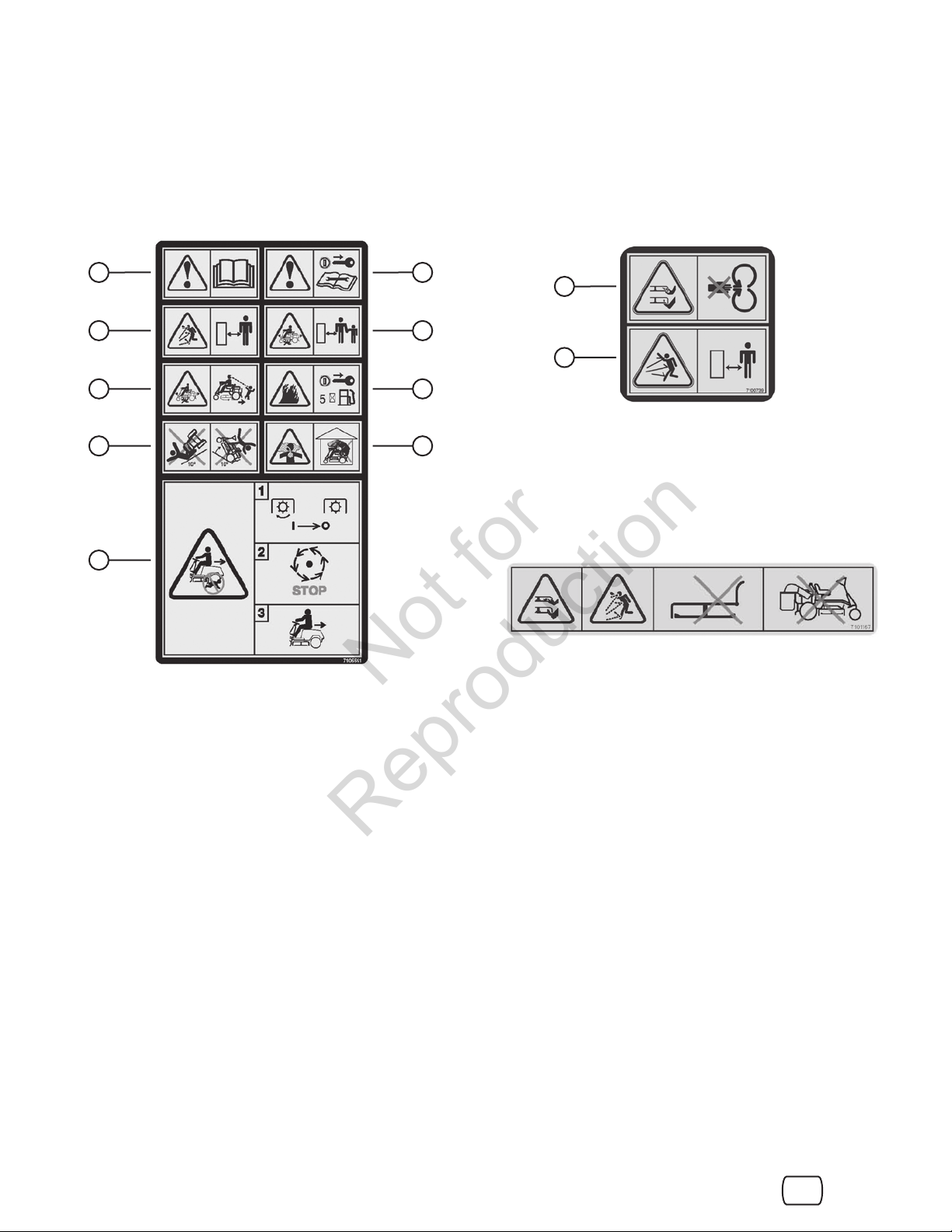
Safety and Instructional Decals
Not for
Reproduction
All DANGER, WARNING, CAUTION and instructional
messages on your rider and mower should be carefully
read and obeyed. Personal bodily injury can result when
these instructions are not followed. The information is for
your safety and it is important! The safety decals below
are on your rider and mower.
A
C
E F
G
B
D
H
If any of these decals are lost or damaged, replace them
at once. See an authorized dealer for replacements.
These labels are easily applied and will act as a constant
visual reminder to you, and others who may use the
equipment, to follow the safety instructions necessary for
safe, effective operation.
A
B
Deck Warning - 7100739
A. Danger: Dismemberment. This mower deck can ampu-
tate limbs. Keep hands and feet away from blades.
B. Danger: Thrown Objects. This machine is capable of
throwing objects and debris. Keep bystanders away.
I
Safety Instructions - 7101166
A. Warning: Read Operator’s Manual. Read and
understand the Operator’s Manual before using this
machine.
B. Warning: Remove Key Before Servicing. Remove the
key and consult technical literature before performing
repairs or maintenance.
C. Danger: Thrown Objects. This machine is capable of
throwing objects and debris. Keep bystanders away.
D. Danger: Dismemberment. This machine can ampu-
tate limbs. Keep bystanders and children away when
engine is running.
E. Danger: Do not mow in reverse unless absolutely
necessary. Look down and behind – before and while
backing.
F. Danger: Fire Hazard. Do not add fuel while engine is
hot or running. Stop engine and allow to cool for 5 minutes prior to adding fuel.
G. Danger: Machine Rollover. Do not use this machine on
slopes greater than 10°.
H. Danger: Carbon Monoxide Poisoning. Do not operate
the engine in an unventilated area.
I. Caution: Disengage mower blades and stop forward
motion before shifting unit into reverse.
Warning - 7101167
Danger: Dismemberment and Thrown Objects Hazard.
Do not mow without discharge chute or entire grass
catcher in place.
en
13
Page 14
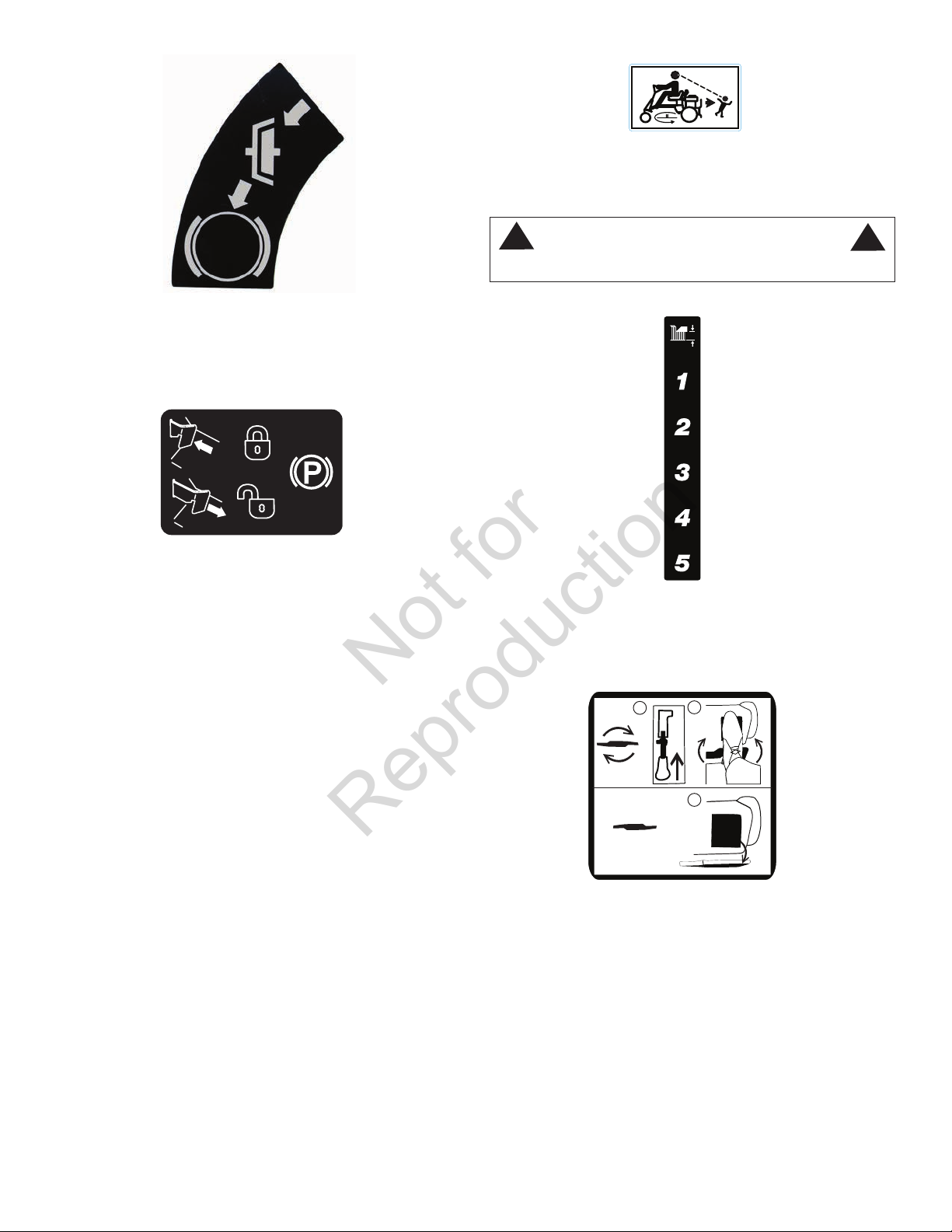
7103440
7104796
Not for
Reproduction
Reverse Lockout Override - 7104796
Identifies location of Reverse Lockout Override Lever.
Refer to “Reverse Lockout Mechanism”.
Clutch/Brake - 7028514
Shows operation of Clutch/Brake pedal. Depress
Clutch/Brake pedal to disengage clutch and apply
brake.
7103219
Park Brake - 7103219
Shows operation of park brake latch. Refer to “Setting
the Park Brake”.
!
Do not mow in reverse unless absolutely necessary.
Identifies height of cut positions. Refer to “Cutting
Height Adjustment”.
WARNING
Height of Cut - 7103440
!
1
1760758
Blade On/Blade Off - 1760758
Shows operation of mower blade. Refer to “Engaging
the Mower Blade” and “Stopping the Engine, Wheel
Drive and Mower Blade”.
2
1
www.snapper.com14
Page 15

Features and Controls
Not for
Reproduction
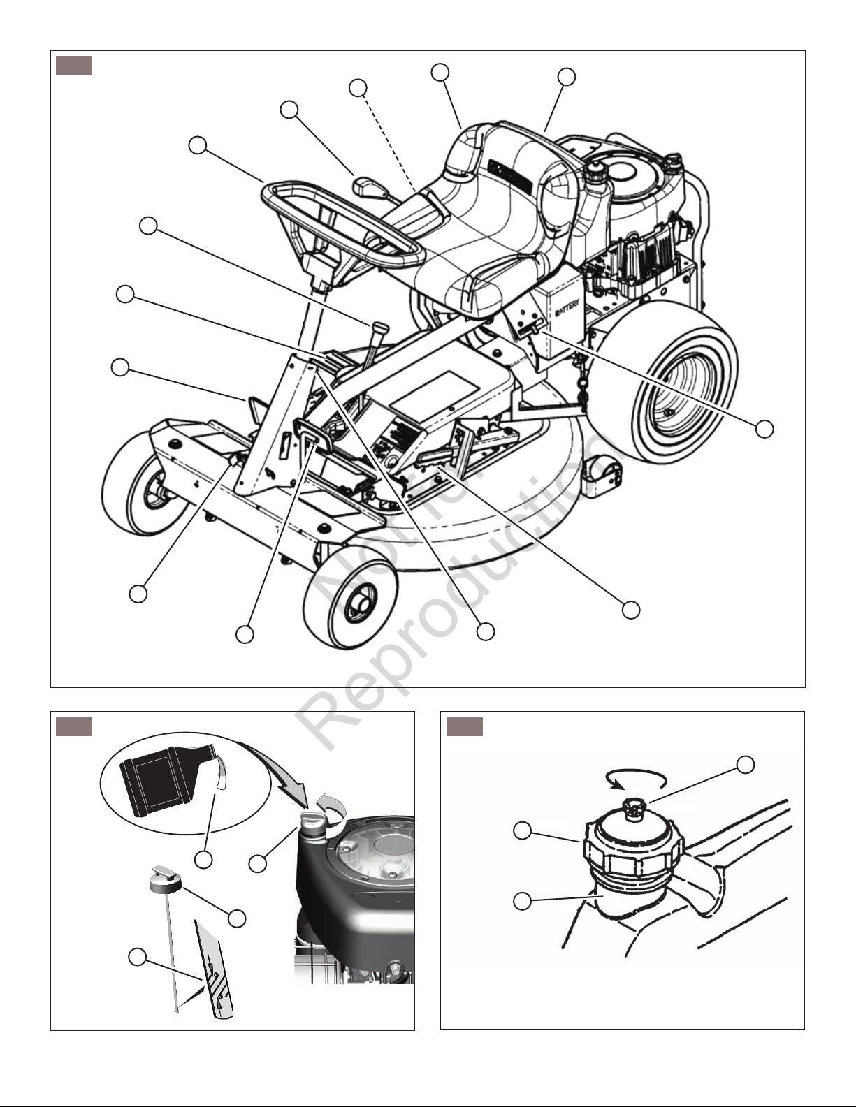
Compare Figure 1 with the table below.
NOTE: The figures and illustrations in this manual are provided for reference only and may differ from your specific
model. Contact your dealer if you have questions.
Ref. Description Icon(s) Icon Definition
L Transmission Shift
Lever - selects transmission speed and
direction
Forward ground
speed
Neutral (no
ground speed)
Ref. Description Icon(s) Icon Definition
A Operator Seat -- --
B Fuel Tank -- --
C Engine Speed
Control - controls
engine speed
D Cutting Height Adjust
Lever (hidden from
view) - adjusts cutting
height
E Ignition Switch (hid-
den from view) starts engine
F Clutch/Brake Pedal -
engages clutch and
brake
G Parking Brake Latch -
locks brake
Choke on
(closed)
Engine speed
fast
Engine speed
low
Cutting height
Engine off
Engine on (run)
Engine start
Clutch engaged
Brake on
(engaged)
Parking brake
on (engaged)
Reverse ground
speed
M Reverse Lockout
Override Lever (hidden from view) - temporarily allows mower
blade to operate
with transmission in
reverse
-- --
Operation
Before Starting
Make the following checks and perform the service
required before each start-up:
1. Check the tire pressure; add or release air as needed
to bring pressure to 15 PSI in front and 12 PSI in rear.
2. Check guards, deflectors and covers to make sure all
are in place and securely tightened.
3. Check engine oil and add oil as needed. Refer to
“How To Check/Add Oil”.
4. Adjust the seat as needed to the most comfortable
position. Refer to “Operator Seat Adjustment”.
5. Check the blade control to insure it works freely. If the
blade pedals are depressed, the blade lever can be
moved manually from “ON” to “OFF” to stop the blade.
6. Check the Reverse Lockout Mechanism. With the
blade pedals depressed, the shift lever must not go
into reverse.
7. Clean the exterior surfaces of the cutting deck and
engine of any accumulation of dirt, grass, oil, etc.
Keep the engine air intake screen and cooling fins
clear at all times.
8. Add fuel to the fuel tank. Refer to “How to Add Fuel”.
H Blade Pedal - locks
mower blade lever in
engage position
I Mulching Cover -- --
J Blade Lever - engag-
es mower blade
K Steering Wheel -
controls direction of
unit
-- --
-- --
Blade on
(engaged)
Blade off (disengaged
Oil Recommendations
We recommend the use of Briggs & Stratton Warranty
Certified oils for best performance. Other high-quality
detergent oils are acceptable if classified for service SF,
SG, SH, SJ or higher. Do not use special additives.
en
15
Page 16
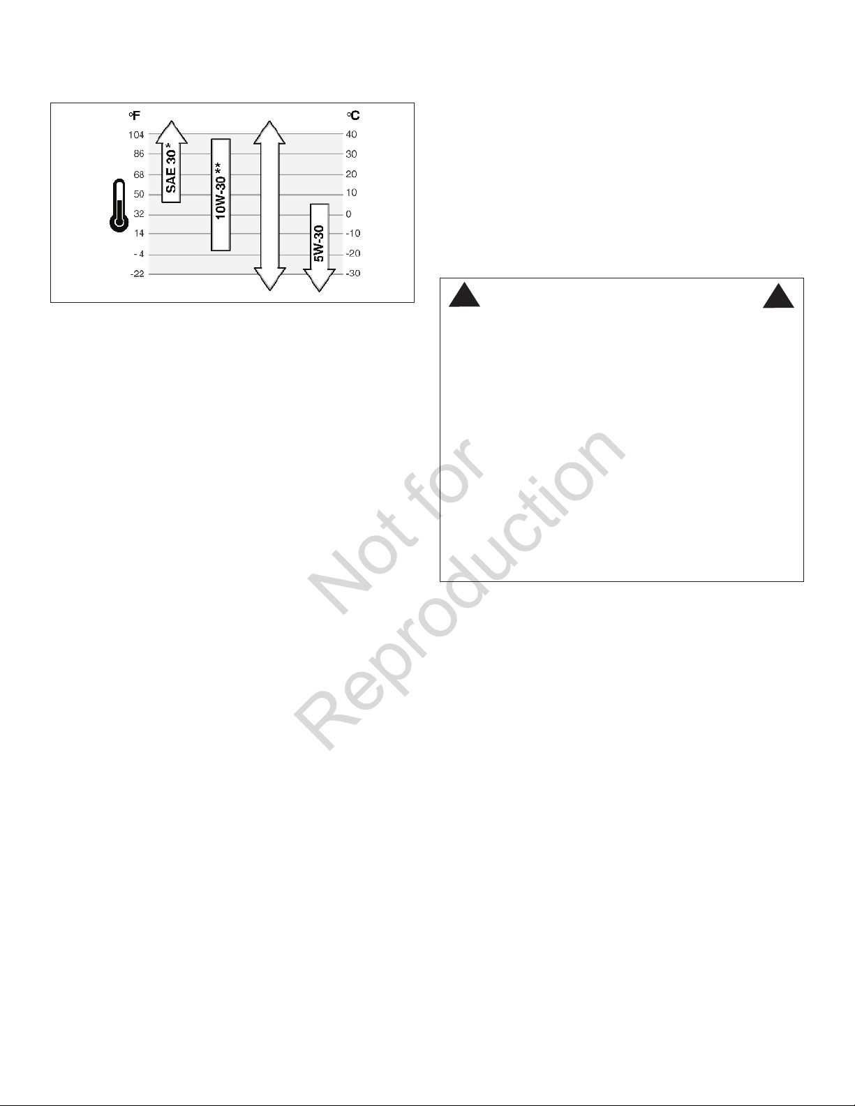
Outdoor temperatures determine the proper oil viscosity for
Not for
Reproduction
the engine. Use the chart to select the best viscosity for the
outdoor temperature range expected.
Synthetic 5W-30
High Altitude
At altitudes over 5,000 feet (1524 meters), a minimum 85
octane/85 AKI (89 RON) gasoline is acceptable. To remain
emissions compliant, high altitude adjustment is required.
Operation without this adjustment will cause decreased
performance, increased fuel consumption, and increased
emissions. See a Briggs & Stratton Authorized Dealer for
high altitude adjustment information.
Operation of the engine at altitudes below 2,500 feet (762
meters) with the high altitude kit is not recommended.
How To Add Fuel
* Below 40°F (4°C) the use of SAE 30 will result in hard starting.
** Above 80°F (27°C) the use of 10W-30 may cause increased oil con-
sumption. Check oil level more frequently.
How To Check/Add Oil
Before adding or checking the oil
• Place engine level.
• Clean the oil fill area of any debris.
1. Remove the dipstick (A, Figure 2) and wipe with a
clean cloth.
2. Insert and tighten the dipstick.
3. Remove the dipstick and check the oil level. It should
be at the top of the full indicator (B, Figure 2) on the
dipstick.
4. If low, add oil slowly into the engine oil fill (C, Figure
2). Do not overfill. After adding oil, wait one minute
and then recheck the oil level.
5. Replace and tighten the dipstick.
Fuel Recommendations
Fuel must meet these requirements:
• Clean, fresh, unleaded gasoline.
• A minimum of 87 octane/87 AKI (91 RON). High altitude use, see below.
• Gasoline with up to 10% ethanol (gasohol) is acceptable.
CAUTION: Do not use unapproved gasolines, such as E15
and E85. Do not mix oil in gasoline or modify the engine to
run on alternate fuels. This will damage the engine components and void the engine warranty.
To protect the fuel system from gum formation, mix a fuel
stabilizer into the fuel. Refer to “Storage”. All fuel is not the
same. If starting or performance problems occur, change
fuel providers or change brands. This engine is certified to
operate on gasoline. The emissions control system for this
engine is EM (Engine Modifications)
!
Fuel and its vapors are extremely flammable and explosive.
Fire or explosion can cause severe burns or death.
When Adding Fuel
• Turn engine off and let engine cool at least 5 minutes
before removing the fuel cap.
• Fill fuel tank outdoors or in well-ventilated area.
• Do not overfill fuel tank. To allow for expansion of the
fuel, do not fill above the bottom of the fuel tank neck.
• Keep fuel away from sparks, open flames, pilot lights,
heat, and other ignition sources.
• Check fuel lines, tank, cap, and fittings frequently for
cracks or leaks. Replace if necessary
• If fuel spills, wait until it evaporates before starting
engine.
1. Clean the fuel cap area of dirt and debris. Remove the
fuel cap (A, Figure 3).
2. Fill the fuel tank with fuel. To allow for expansion of the
fuel, do not fill above the bottom of the fuel tank neck
(B, Figure 3).
3. Reinstall the fuel cap. Make sure the vent (C, Figure
3) is open after refueling.
WARNING
!
Operator Seat Adjustment
1. With the engine stopped, loosen the two adjusting
knobs (A, Figure 4) and move the seat to the desired
position. After adjustment, tighten the knobs securely.
NOTE: If the seat does not move after loosening the knobs,
it may be necessary to loosen the 5/16” patch lock screws
or hex nuts (B, Figure 4) located at the rear of the seat.
www.snapper.com16
Page 17
Starting the Engine
Not for
Reproduction
WARNING
POISONOUS GAS HAZARD. Engine exhaust contains carbon
monoxide, a poisonous gas that could kill you in minutes. You
CANNOT see it, smell it, or taste it. Even if you do not smell exhaust
fumes, you could still be exposed to carbon monoxide gas. If you
start to feel sick, dizzy, or weak while using this product, shut it
off and get to fresh air RIGHT AWAY. See a doctor. You may have
carbon monoxide poisoning.
• Operate this product ONLY outside far away from windows, doors and vents
to reduce the risk of carbon monoxide gas from accumulating and potentially
being drawn towards occupied spaces.
• Install battery-operated carbon monoxide alarms or plug-in carbon monoxide
alarms with battery back-up according to the manufacturer’s instructions.
Smoke alarms cannot detect carbon monoxide gas.
• DO NOT run this product inside homes, garages, basements, crawlspaces,
sheds, or other partially-enclosed spaces even if using fans or opening doors
and windows for ventilation. Carbon monoxide can quickly build up in these
spaces and can linger for hours, even after this product has shut off.
• ALWAYS place this product downwind and point the engine exhaust away
from occupied spaces.
Electric Start
IMPORTANT: When the ignition key is turned to “START”,
the engine will turn over, but will not start unless the Clutch/
Brake pedal is pressed all the way down, and the Blade
Lever is in the “OFF” position. The operator should be in
the seat.
Start the engine as follows:
1. Open the vent (B, Figure 3) on the fuel filler cap (A)
by turning counterclockwise.
IMPORTANT: Failure to open the vent on the fuel filler cap
can cause the engine to stall.
2. Move the transmission shift lever to the (N) Neutral
position. Refer to “Wheel Drive”.
IMPORTANT: DO NOT start the engine with the transmission shift lever in a drive position.
!
It is possible to start the engine with the transmission
shift lever in a drive position. Follow starting instructions
carefully.
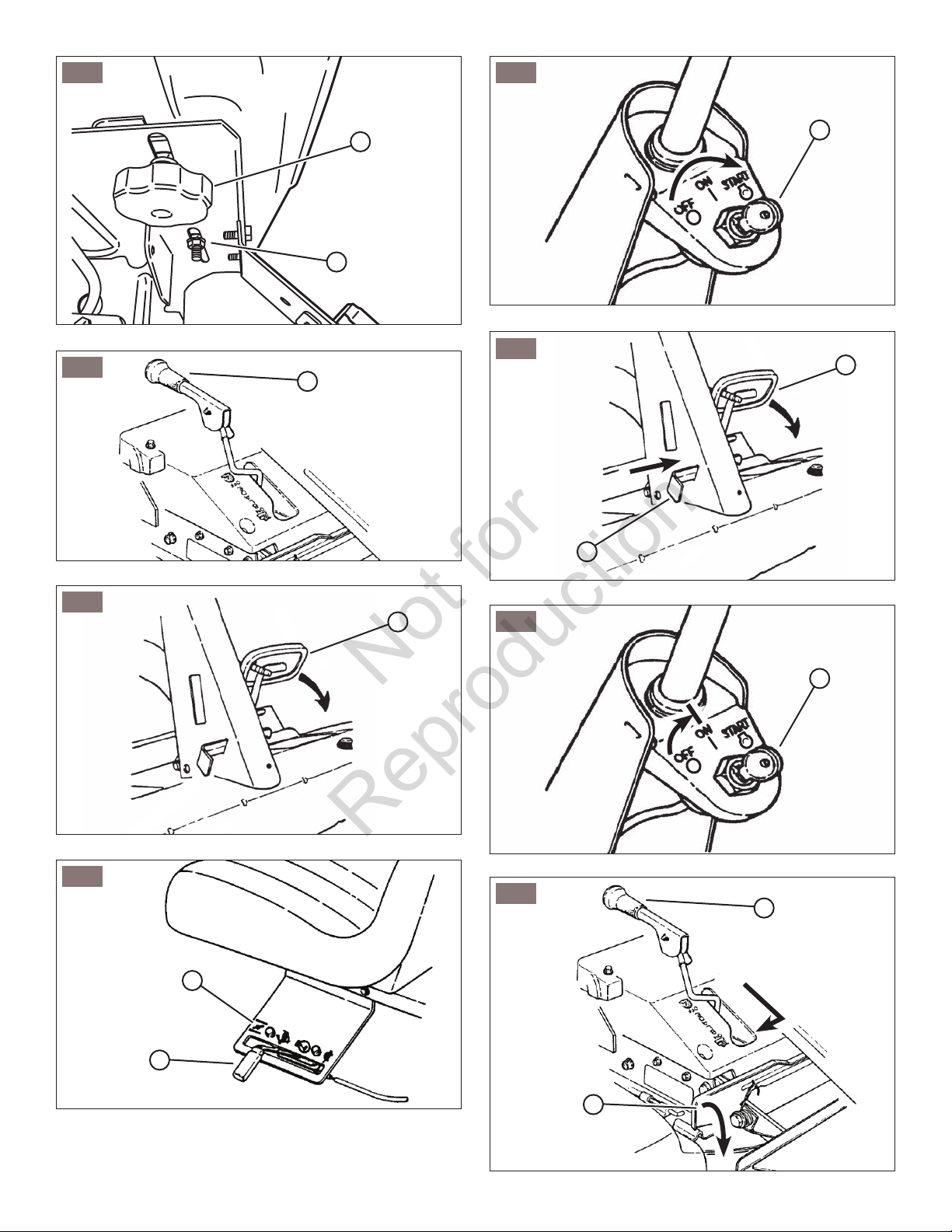
3. Make certain the Blade Lever (A, Figure 5) is in the
“OFF” position.
4. Depress the Clutch/Brake Pedal (A, Figure 6) all the
way down and hold while starting the engine.
5. Move the engine speed control (A, Figure 7) to the
choke position (B) to start a cold engine.
6. Turn the ignition key (A, Figure 8) to the “START”
position until the engine starts.
NOTE: If after 5 seconds of cranking the engine does not
start, release the key, make sure the Clutch/Brake Pedal is
fully depressed, and attempt starting again after waiting for
approximately 20 seconds.
7. After the engine starts, move the engine speed control
to the “FAST” position and allow a brief warm-up until
engine runs smooth.
8. Should the battery be too weak to start the engine,
WARNING
!
refer to “Engine (Manual Start)” to manually start the
electric start engines.
9. On Model E2813523BVE, the engine is equipped
with a fuel shut-off solenoid. If the battery is dead, the
engine can be started with the recoil back-up starter if
the engine speed control is in the choke position (HOT
engine or COLD engine).
Manual Start
IMPORTANT: When the key is turned to “ON”, and the
recoil handle is pulled, the engine will turn over, but will not
start unless the Clutch/Brake Pedal is pressed all the way
down with the Park Brake engaged, and the Blade Lever is
in the “Off” position.
Start the engine as follows:
1. Open the vent (B, Figure 3) on the fuel filler cap (A)
by turning counterclockwise.
IMPORTANT: Failure to open the vent on the fuel filler cap
can cause the engine to stall.
2. Move the transmission shift lever to the (N) Neutral
position. Refer to the section entitled “Wheel Drive”.
IMPORTANT: DO NOT start the engine with the transmission shift lever in a drive position.
!
It is possible to start the engine with the transmission
shift lever in a drive position. Follow starting instructions
carefully.
3. Make certain the Blade Lever (A, Figure 5) is in the
“OFF” position.
4. Depress the Clutch/Brake Pedal (A, Figure 9) all the
way down, move the park brake latch (B) over, and
release the clutch/brake pedal to set the park brake.
5. Move the engine speed control (A, Figure 7) to the
choke position (B) to start a cold engine.
6. Turn the key (A, Figure 10) to the “ON” position.
7. Pull the starter rope, located on the engine recoil, with
a smooth, even motion until the engine starts.
NOTE: Always guide the starter rope back into the recoil
housing. Never allow rope to snap back.
After the engine starts, move the engine speed control
to the “FAST” position.
8. Allow a brief warm-up until the engine runs smooth.
WARNING
!
Engaging the Mower Blade
!
Once blade is disengaged, it should come to a complete stop in 3 seconds or less. If the blade continues to
rotate after 3 seconds, the blade brake must be adjusted. Return machine to an authorized dealer for adjustment. DO NOT CONTINUE to operate machine until
blade brake is adjusted and functioning properly.
WARNING
en
!
17
Page 18
1. With the engine running, move the engine speed con-
Not for
Reproduction
trol to the “FAST” position.
2. Move the blade lever (A, Figure 11) forward to the
“ON” position, then press the blade pedals (B) to hold
the blade lever in the “ON” position.
Engaging the Wheel Drive
1. With the engine running, adjust the engine speed control to the “FAST” position.
2. Depress the clutch/brake pedal (A, Figure 6).
3. Place the transmission shift lever (A, Figure 12) into
the first forward speed notch (B).
4. Release the clutch/brake pedal to begin forward
motion.
5. During forward motion, the transmission shift lever
may be placed in any desired forward speed without
depressing the clutch/brake pedal.
NOTE: For best cutting results, move the transmission
shift lever into a slow forward speed and the engine speed
control to a fast position. This combination will allow the
mower blades to lift the grass while cutting smoothly and
evenly.
!
DO NOT operate blades in reverse. STOP BLADES.
LOOK and SEE behind and down for children, pets and
hazards before and while backing.
WARNING
!
Stopping the Engine,
Wheel Drive and Mower Blade
!
DO NOT leave the machine with the engine running.
STOP Blade. STOP engine. Shift to neutral and engage
park brake. Remove key.
Engine
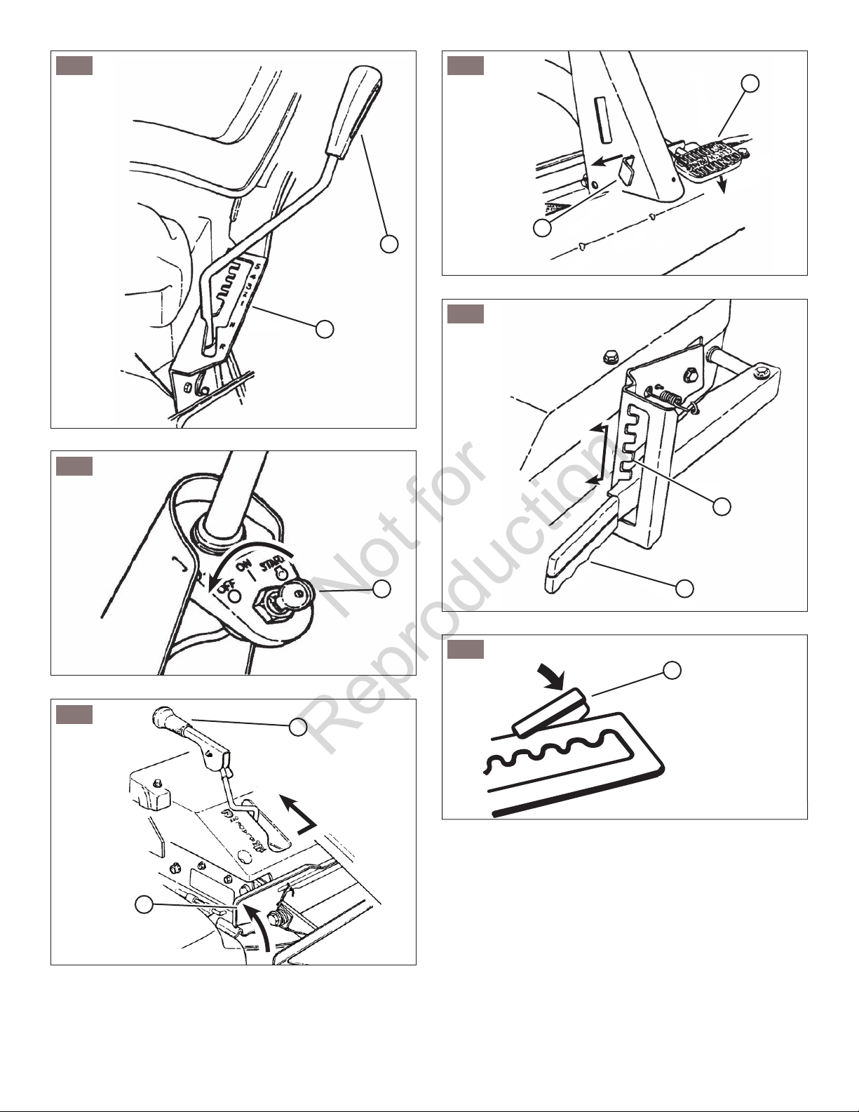
1. Stop the engine by turning the key (A, Figure 13) to
the “OFF” position.
Wheel Drive
1. Stop motion of the Rear Engine Rider by pushing the
clutch/brake pedal (A, Figure 6) all the way down to
apply the brake.
Mower Blade
1. Stop the mower blade by releasing the blade pedals
(A, Figure 14) or moving the blade lever (B) rearward
to the “OFF” position.
WARNING
!
!
Once blade is disengaged, it should come to a complete stop in 3 seconds or less. If the blade continues to
rotate after 3 seconds, the blade brake must be adjusted. Return machine to an authorized dealer for adjustment. DO NOT CONTINUE to operate machine until
blade brake is adjusted and functioning properly.
WARNING
!
Setting the Park Brake
1. To set the park brake, depress the clutch/brake pedal
(A, Figure 9) all the way down, slide the park brake
latch (B) all the way in to the engaged position, and
release the clutch/brake pedal. A detent in the park
brake latch will keep the park brake engaged.
!
DO NOT park the machine on slopes.
2. Release the park brake by pressing down firmly on the
clutch/brake pedal (A, Figure 15). The park brake
latch (B) is spring-loaded, and will slide back to the
disengaged position unassisted.
WARNING
!
Cutting Height Adjustment
1. Adjust the cutting height by raising or lowering the
deck lift lever (A, Figure 16) into the desired height of
cut notch (B).
Reverse Lockout Mechanism
This riding mower has a Reverse Lockout Mechanism,
which prevents the mower from being shifted into reverse
with the blade running. However, if you operate your
mower near roadways or use attachments that require
quicker shifting to reverse, there is an override lever provided. This lever will allow reverse operation until the blade
pedals are released, at which time the system will return to
its Reverse Lockout mode.
This feature should never be selected unless you are
absolutely sure that no children or others are present in the
mowing area and that all children are away and supervised
by a responsible adult.
Reverse Lockout Mechanism Override
1. Stop the machine. Stop the blade.
2. Depress and hold the Override Lever (A, Figure 17).
3. Depress and hold the Blade Pedals. Release the
Override Lever.
4. Move the blade lever forward to “ON” position.
LOOK and SEE behind and down for children, pets and
hazards before and while backing.
!
WARNING
!
www.snapper.com18
Page 19
IMPORTANT: DO NOT use the Reverse Lockout
Not for
Reproduction
Mechanism Override as the normal operating mode. To
return to the Reverse Lockout Mechanism mode, release
blade pedals to turn blade off. The Override will reset to
Reverse Lockout. Check the Reverse Lockout Mechanism
frequently for proper function. With the blade pedals
depressed, the shift lever must not go into reverse. DO
NOT operate machine if Reverse Lockout Mechanism is
not functioning properly. Contact your authorized dealer for
assistance.
!
LOOK and SEE behind and down for children, pets and
hazards before and while backing.
BLADES must be turned off before backing machine.
DO NOT allow children on machine (even with blades
off) or in yard when mowing.
DANGER
!
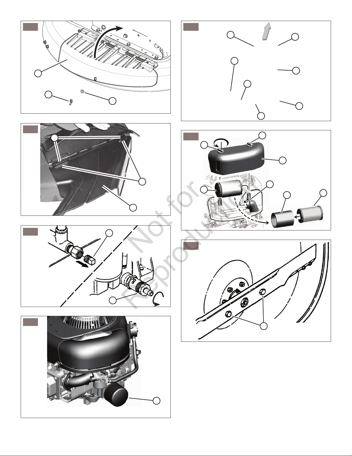
Discharge Deflector Installation
!
DO NOT attempt any adjustments, maintenance, service
or repairs with the engine running. STOP engine. STOP
blade. Engage parking brake. Remove key. Remove
spark plug wire from spark plug and secure away from
plug. Engine and components are HOT. Avoid serious
burns, allow all parts to cool before working on machine.
Fuel Filler Cap and vent must be closed securely to prevent fuel spillage.
1. Remove the nut (A, Figure 18) and washer (B) securing the bottom edge of the mulching cover (C) to the
mower deck.
WARNING
!
Maintenance
Maintenance Chart
!
DO NOT attempt any adjustments, maintenance, service
or repairs with the engine running. STOP engine. STOP
blade. Engage parking brake. Remove key. Remove
spark plug wire from spark plug and secure away from
plug. Engine and components are HOT. Avoid serious
burns, allow all parts to cool before working on machine.
Fuel Filler Cap and vent must be closed securely to prevent fuel spillage.
TRACTOR AND MOWER
Every 8 Hours or Daily
Check safety interlock system
Clean debris off tractor and mower deck
Clean debris from engine compartment
Every 25 Hours or Annually *
Check tire pressure
Check mower blade stopping time
Check tractor and mower for loose hardware
Every 50 Hours or Annually *
Clean battery and cables
Check tractor brakes
See Dealer Annually to
Lubricate tractor and mower
Check mower blades **
WARNING
!
!
The mulching cover must remain on the machine at all
times. Do not remove.
2. Raise the mulching cover. Replace the washer and nut
onto the retaining bolt in the deck, tightening securely.
3. Install the discharge deflector (A, Figure 19) to the
mower deck, making sure that the slots (B) in the
deflector fit over the locking tabs (C) on the mulching
cover hinge bracket.
4. Lower the mulching cover.
5. To remove the discharge deflector:
• Raise the mulching cover.
• Lift and remove the discharge deflector from the
mower deck.
• Remove the nut and washer from the retaining bolt in
the deck.
• Lower the mulching cover, securing with the washer
and nut. Tighten securely.
WARNING
!
* Whichever comes first
** Check blades more often in regions with sandy soils or
high dust conditions.
en
19
Page 20
ENGINE
Not for
Reproduction
First 5 Hours
Change engine oil
Every 8 Hours or Daily
Check engine oil level
Every 25 Hours or Annually *
Clean engine air filter and pre-cleaner **
Every 50 Hours or Annually *
Change engine oil
Replace oil filter
Annually
Replace air filter
Replace pre-cleaner
See Dealer Annually to
Inspect muffler and spark arrester
Replace spark plug
Replace fuel filter
Clean engine air cooling system
* Whichever comes first
** Clean more often in dusty conditions or when airborne
debris is present.
Change Oil Filter (if equipped)
Some models are equipped with oil filter. For replacement
intervals, see the Maintenance chart.
1. Drain the oil from the engine. Refer to “Change Engine
Oil”.
2. Remove the oil filter (A, Figure 21) and dispose of
properly.
3. Before you install the new oil filter, lightly lubricate the
oil filter gasket with fresh, clean oil.
4. Install the oil filter by hand until the gasket contacts
the oil filter adapter, then tighten the oil filter 1/2 to 3/4
turns.
5. Add oil. Refer to “How to Check/Add Oil” in the
Operation section.
6. Start and run the engine. As the engine warms up,
check for oil leaks.
7. Stop the engine and check the oil level. It should be at
the top of the full indicator on the dipstick.
Service Air Filter
!
Fuel and its vapors are extremely flammable and explosive.
Fire or explosion can cause severe burns or death.
• Never start or run the engine with the air cleaner
assembly (if equipped) or the air filter (if equipped)
removed.
WARNING
!
Engine Maintenance
!
DO NOT attempt any adjustments, maintenance, service
or repairs with the engine running. STOP engine. STOP
blade. Engage parking brake. Remove key. Remove
spark plug wire from spark plug and secure away from
plug. Engine and components are HOT. Avoid serious
burns, allow all parts to cool before working on machine.
Fuel Filler Cap and vent must be closed securely to prevent fuel spillage.
WARNING
!
Change Engine Oil
Used oil is a hazardous waste product and must be disposed of properly. Do not discard with household waste.
Check with your local authorities, service center, or dealer
for safe disposal/recycling facilities.
1. Place bricks or wooden blocks under the front wheels
to lower the rear of the engine.
2. Loosen or remove the oil fill cap on the engine.
3. Place a 2 quart minimum capacity container under the
end of the oil drain (Figure 20).
4. Remove or open the oil drain plug (A or B, Figure
20), depending upon the type of oil drain plug the
engine is equipped with.
5. After all the oil has drained, replace or close the
drain plug, and wipe up any oil that may have spilled.
Dispose of used oil properly.
6. Fill the engine with new oil. Refer to “How To Check/
Add Oil” in the Operation Section.
NOTICE: Do not use pressurized air or solvents to clean
the filter. Pressurized air can damage the filter and solvents
will dissolve the filter.
The air filter system uses either a flat or a cylindrical cartridge air filter. Some models are also equipped with a precleaner that can be washed and reused.
Flat Air Filter
1. Pull up on the cover handle (A, Figure 22). Rotate the
cover handle toward the engine and then remove the
cover (B).
2. Remove the pre-cleaner (C, Figure 22), if equipped,
and the filter (D).
3. To loosen debris, gently tap the filter on a hard surface.
If the filter is excessively dirty, replace with a new filter.
4. Wash the pre-cleaner in liquid detergent and water.
Then allow it to thoroughly air dry. Do not oil the precleaner.
5. Assemble the dry pre-cleaner and the filter into the
engine base (E, Figure 22).
6. Align the tabs (F, Figure 22) on the cover with the
slots (G) in the blower housing. Rotate the cover handle back and push down to lock in place.
Cylindrical Cartridge Air Filter
1. Remove the fasteners (A, Figure 23) and the air filter
cover (B).
2. To remove the filter (C, Figure 23), lift the end of the
filter and then pull the filter off the intake (D).
3. Remove the pre-cleaner (E, Figure 23), if equipped,
from the filter.
www.snapper.com20
Page 21
4. To loosen debris, gently tap the filter on a hard surface.
Not for
Reproduction
If the filter is excessively dirty, replace with a new filter.
5. Wash the pre-cleaner in liquid detergent and water.
Then allow it to thoroughly air dry. Do not oil the precleaner.
6. Assemble the dry pre-cleaner to the filter.
7. Install the filter on the intake. Push the end of the filter
into the base as shown. Make sure filter fits securely in
the base.
8. Install air filter cover and secure with fasteners.
Rider Maintenance
!
Once blade is disengaged, it should come to a complete stop in 3 seconds or less. If the blade continues to
rotate after 3 seconds, the blade brake must be adjusted. Return machine to an authorized dealer for adjustment. DO NOT CONTINUE to operate machine until
blade brake is adjusted and functioning properly.
2. If the blade continues to rotate longer than 3 seconds
do not operate the machine. Contact your dealer for
assistance.
WARNING
!
!
DO NOT attempt any adjustments, maintenance, service
or repairs with the engine running. STOP engine. STOP
blade. Engage parking brake. Remove key. Remove
spark plug wire from spark plug and secure away from
plug. Engine and components are HOT. Avoid serious
burns, allow all parts to cool before working on machine.
Fuel Filler Cap and vent must be closed securely to prevent fuel spillage.
WARNING
!
Check Mower Blade
1. Follow the WARNING statement found on this page.
2. Check the fuel level in the tank. If over 3/4 full, remove
the tank. Refer to “Removing Fuel Tank”. If 3/4 or less,
proceed to the next step.
3. Carefully stand the Rear Engine Rider on the rear bumper.
!
Remove the battery if the Rear Engine Rider will be left
standing on the rear bumper for longer than 2 hours.
Refer to “Battery Removal”. DO NOT use a cutting
blade that shows signs of excessive wear or damage
on the Rear Engine Rider. Refer to the “Mower Blade
Replacement” for proper blade inspection and service
procedures.
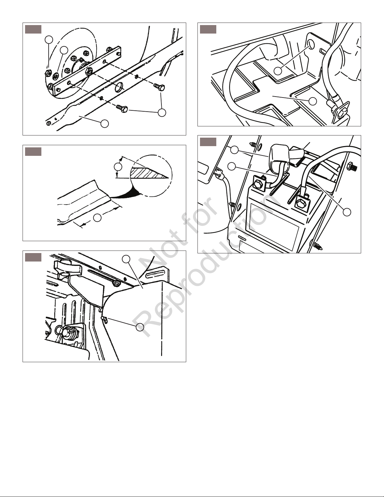
4. Check the torque of the blade mounting bolts (A,
Figure 24). As necessary, torque to 30 to 40 ft. lbs.
5. Check the blade for sharpness, wear and damage.
Refer to “Blade Wear Limits”.
6. Check the blade for straightness. Refer to “Adjusting
Mower Blade”.
DANGER
!
Blade Brake
Service Brake / Park Brake
1. Check the machine brake for proper function:
• Engage the park brake, and push the machine. The
rear tires should skid.
• Drive the machine forward and apply the brake.
The machine should come to a complete stop in
less than 5 ft.
2. If the brakes are not functioning properly, brake
adjustment must be completed before operating the
machine. Contact your authorized dealer.
Safety Interlock System Checks
Perform the following interlock system checks periodically during the operating season. Contact your authorized
Snapper dealer if you have questions.
!
DO NOT operate machine if any safety interlock or
safety device is not in place and functioning properly.
DO NOT attempt to defeat, modify or remove any safety
device.
Engine must not start if:
1. The Clutch/Brake Pedal is not fully depressed OR,
2. The Blade Control is in the “ON” (blades engaged)
position.
Engine should start if:
1. The Blade Control is in the “OFF” (blades disengaged)
position AND,
2. The Clutch/Brake Pedal is fully depressed.
Engine and blades must stop if:
1. The operator rises off of seat with Blade Control in
“ON” (blades engaged) position OR,
2. The operator rises off of seat with Clutch/Brake Pedal
not fully depressed.
WARNING
!
!
The following procedure requires the engine and blades
to be operated. Exercise extreme caution. Clear area of
loose parts & tools first. Only operate blades when seated
in the operator’s seat.
1. Check the blade brake for proper function. The blade
should stop rotating in 3 seconds or less after moving
the blade control lever to the “OFF” position or after
releasing the blade pedals.
WARNING
!
Reverse Lockout Mechanism
Check the function of the Reverse Lockout Mechanism
with the engine off.
1. Depress and hold the blade pedals.
2. Depress and hold the clutch/brake pedal.
3. With Steps 1 and 2 performed, the shift lever must not
go into reverse.
en
21
Page 22
!
Not for
Reproduction
DO NOT operate machine if Reverse Lockout
Mechanism is not functioning properly. Contact your
dealer immediately for assistance.
WARNING
!
Battery Maintenance
Perform battery maintenance as required. Refer to
“Battery”.
Mower Deck Levelness
Check the mower deck for proper level. Adjust as
required. Refer to “Mower Deck Adjustment – Levelness”.
Clean Mower Deck
!
DO NOT attempt any adjustments, maintenance, service
or repairs with the engine running. STOP engine. STOP
blade. Engage parking brake. Remove key. Remove
spark plug wire from spark plug and secure away from
plug. Engine and components are HOT. Avoid serious
burns, allow all parts to cool before working on machine.
Fuel Filler Cap and vent must be closed securely to prevent fuel spillage.
1. Check the fuel level in the tank. If over 3/4 full, remove
the tank. Refer to “Removing Fuel Tank”. If 3/4 or less,
proceed to the next step.
2. Carefully stand the Rear Engine Rider on the rear bumper.
3. Clean the underside of the mower deck, removing all
accumulation of grass clippings and debris.
4. Clean the top of the deck, removing all grass clippings
and debris.
WARNING
!
Fuel Filter
IMPORTANT: Service the fuel filter on a COLD ENGINE
ONLY!
IMPORTANT: To stop the flow of fuel, the fuel tank (C,
Figure 25) may be removed from the bracket and set on
the floor so the fuel level will be below the filter. Refer to
“Removing Fuel Tank”.
1. Remove the hose clamps (B, Figure 25) from the fuel
filter (A).
2. Remove the fuel lines from filter. Discard the filter.
3. Install a new fuel filter.
4. Reinstall the fuel tank into the bracket (if removed).
5. Carefully reinstall the fuel clamps.
6. Check the fuel system for leaks.
Lubrication – Grease Fittings
The following components on the Rear Engine Rider are
equipped with grease fittings and require periodic lubrication. Apply General Purpose grease (NLGI No.2) with a
grease gun.
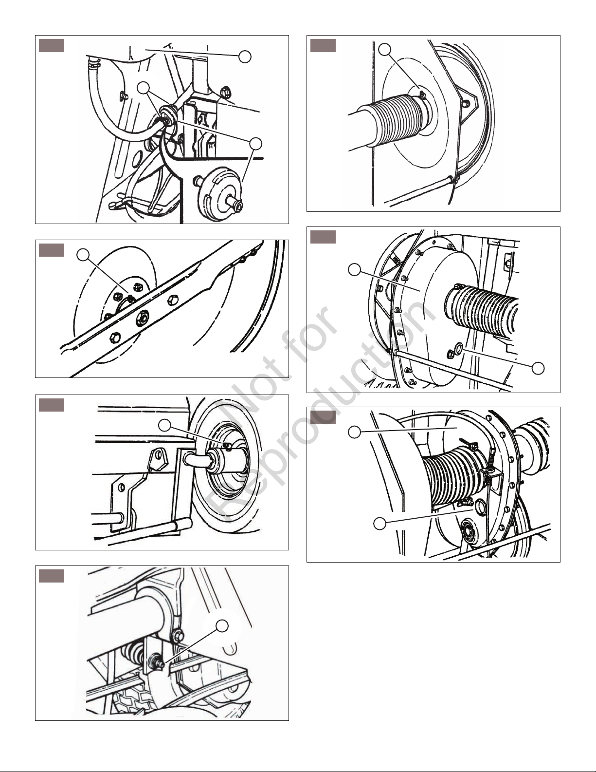
1. Mower Blade Spindle
1. Follow the WARNING statement found on this page.
2. Check the fuel level in tank. If over 3/4 full, remove the
tank. Refer to “Removing Fuel Tank”. If 3/4 or less, proceed to the next step.
3. Carefully stand the Rear Engine Rider on the rear bumper.
4. Lubricate the spindle grease fitting (A, Figure 26) with
three shots of general purpose grease from a grease
gun.
NOTE: Some models are equipped with sealed spindle
bearings, which do not require lubrication.
IMPORTANT: If the Rear Engine Rider will be on its rear
bumper for longer than two hours, remove the battery.
Refer to “Battery Removal”.
2. Front Wheel Bearing
Lubricate the front wheel grease fittings (A, Figure 27)
with five shots of general purpose grease, from a grease
gun.
3. Shift Lever
Lubricate the shift lever grease fitting (A, Figure 28) with
two shots of general purpose grease from a grease gun.
4. Rear Axle Bearing
1. The grease fitting (A, Figure 29) on the left rear axle
bearing requires three shots of general purpose grease
from grease gun.
2. The right rear axle bearing is lubricated by the
differential lubricant and requires no grease.
Lubrication - Mower Deck Linkage
Lubricate all mower deck linkage pivot points with a light
coat of motor oil.
Lubrication - Differential / Chain Case
1. Stand the rear engine rider on its rear bumper and
check the fill/level plug (A, Figure 30) on the differential (B) for cracks and wear. Replace the fill/level plug if
signs of wear are visible.
IMPORTANT: If the Rear Engine Rider will be on its rear
bumper for longer than two hours, remove the battery.
Refer to “Battery Removal”.
2. To check lubricant, remove the fill/level plug and visually inspect for lubricant on the internal parts of the
differential. If no lubricant is visible on the internal parts
of the differential, add transmission grease as needed.
IMPORTANT: Overfilling of the differential with lubricant
will cause lubricant to leak onto drive components of the
Rear Engine Rider.
3. Check the fill/level plug (A, Figure 31) on the chain
case (B) for damage. If signs of wear or cracks are visible, replace with a new plug.
4. To check lubricant in the chain case, remove the fill/
level plug and look for lubricant on the internal components of the chain case. If no lubricant is visible, add
transmission grease as needed.
www.snapper.com22
Page 23
Miscellaneous Items
Not for
Reproduction
In addition to regular maintenance, the following
components of the Rear Engine Rider should be carefully
inspected regularly for wear or damage.
1. All bushings and pivot areas.
2. Check both front wheel king pins.
3. Transmission shift lever and detent.
4. Clutch disc.
5. Clutch yoke.
6. Mower deck linkage and pivot areas.
Replace worn or damaged parts. Use only factory authorized replacement parts or like parts when making repairs.
Removing the Fuel Tank
NOTE: Before removing the fuel tank from the rear engine
rider, move the rider outdoors where fumes can easily dissipate.
1. From the left side of the machine, pull the fuel tank (A,
Figure 32) straight up and away from the fuel tank
bracket (B).
2. Holding the fuel tank, remove the fuel filler cap (C,
Figure 32) and pour any remaining fuel into an
approved container.
Storage
Note: If desired, the Rear Engine Rider can be stored on
the rear bumper.
1. Thoroughly clean the Rear Engine Rider by removing
all grass clippings and debris.
2. Perform maintenance and lubrication as required.
3. Drain the fuel from the fuel tank (unless using a fuel
stabilizer - Refer to “Fuel System”).
4. Start the engine and allow it to run until the engine runs
out of fuel. This allows the carburetor and fuel system
to remain clean during storage.
5. Remove the battery. Refer to “Battery Storage”.
6. Close the vent on the fuel filler cap.
7. If desired, carefully stand the Rear Engine Rider on its
rear bumper in the desired location for storage.
Fuel System
Fuel can become stale when stored over 30 days. Stale
fuel causes acid and gum deposits to form in the fuel
system or on essential carburetor parts. To keep fuel
fresh, use Briggs & Stratton® Advanced Formula Fuel
Treatment & Stabilizer, available wherever Briggs &
Stratton genuine service parts are sold.
For engines equipped with a FRESH START® fuel cap,
use Briggs & Stratton FRESH START® available in a
drip concentrate cartridge.
There is no need to drain gasoline from the engine if a
fuel stabilizer is added according to instructions. Run the
engine for 2 minutes to circulate the stabilizer throughout
the fuel system before storage.
If gasoline in the engine has not been treated with a fuel
stabilizer, it must be drained into an approved container.
Run the engine until it stops from lack of fuel. The use of a
fuel stabilizer in the storage container is recommended to
maintain freshness.
Engine Adjustments and Repairs
Engine adjustments and/or repairs should be performed by
an authorized dealer.
Mower Deck and Component Adjustments
!
DO NOT attempt any adjustments, maintenance, service
or repairs with the engine running. STOP engine. STOP
blade. Engage parking brake. Remove key. Remove
spark plug wire from spark plug and secure away from
plug. Engine and components are HOT. Avoid serious
burns, allow all parts to cool before working on machine.
Fuel Filler Cap and vent must be closed securely to prevent fuel spillage.
The following mower deck and component adjustments
and repairs can be made by the owner. However, if there
is difficulty in achieving these adjustments and repairs, it
is recommended that these repairs be made by an authorized dealer.
WARNING
!
Mower Deck Adjustment (Side-To-Side
Levelness)
Before making deck leveling adjustments, check the tire
pressure. Front tires 15 PSI, rear tires 12 PSI. If tires are
properly inflated and mowing is still uneven, adjust side-toside deck levelness.
1. Place the Rider on a smooth level surface.
2. Turn the engine off and remove the key. Remove the
spark plug wire from the spark plug and secure the
wire away from the plug.
3. Place a piece of angle iron, pipe, or similar object
under the rear center of the deck.
4. Remove the rear hanger chains (A, Figure 34) and
allow rear center of the deck to rest on the angle iron.
5. Measure the distance from the blade tips to the floor.
If the measurement is within 1/8” from side-to-side, the
deck attitude is satisfactory. If difference from side-toside is greater than 1/8”, continue with adjustment.
6. Loosen the hardware (A, Figure 33) that retains the
left side of the blade pedal (B).
7. Move the lift arm (C, Figure 33) up or down as
required until the blade tips are within 1/8” of each
other.
8. Tighten the hardware loosened in Step 6. Recheck
both sides of the deck for correct levelness.
9. Readjust the rear hanger chain pivots (B, Figure 34)
to align with the holes in the support brackets (D).
10.Remove the angle iron, pipe, or similar object, and proceed to check front to rear levelness.
en
23
Page 24
Mower Deck Adjustment (Front-to-Rear
Not for
Reproduction
Levelness)
With the Rear Engine Rider on a smooth, level surface,
rotate the blade until the blade tips are at the front and rear
of the deck. Measure the distance from the blade tips to
the floor (Figure 34). The distance should be the same, or
the rear 1/8” to 1/4” lower than the front. If the rear blade
tip is higher than the front, or is more than 1/4” lower than
the front, proceed with adjustment.
1. Remove the rear hanger chains (A, Figure 34).
2. Turn each hanger pivot (B, Figure 34) the same num-
ber of rotations on the eye-bolt to raise or lower the
rear of the deck.
3. Reinstall the rear hanger chains and measure the
blade tips again.
4. Repeat Steps 1 through 3 until proper levelness is
obtained.
Rear Engine Rider Drive Components
!
DO NOT attempt any adjustments, maintenance, service
or repairs with the engine running. STOP engine. STOP
blade. Engage parking brake. Remove key. Remove
spark plug wire from spark plug and secure away from
plug. Engine and components are HOT. Avoid serious
burns, allow all parts to cool before working on machine.
Fuel Filler Cap and vent must be closed securely to prevent fuel spillage.
Service Brake / Park Brake Adjustment
Test the wheel brake on a dry concrete surface. When
properly adjusted, the Rear Engine Rider will stop within 5
feet from fastest speed. If stopping distance is more than 5
feet, the wheel brake should be adjusted as follows:
1. Follow the WARNING statement found on this page.
2. Check the fuel level in tank. If over 3/4 full, remove
tank. Refer to “Removing The Fuel Tank”. If 3/4 or
less, proceed to the next step.
3. Carefully stand the Rear Engine Rider on its rear bumper.
4. Depress the clutch/brake pedal (A, Figure 9) all the
way down. Move and hold the park brake lever (B) in
the “ON” position and release the clutch/brake pedal to
set the park brake.
5. Measure the distance (A, Figure 35) between the
end of the clutch/brake cable (B) and the bottom of
the housing (C). The measurement should be no less
than 1/2” and no greater than 3/4”.
NOTE: The cotter pin, brake spring, and clutch yoke (D, E,
and F, Figure 33) are noted for reference purposes only.
6. If the measurement is less than 1/2” or greater than
3/4”, loosen the two jam-nuts (A, Figure 36). Hold the
clutch/brake cable (B) to the chain case bracket.
7. Adjust the cable up or down using the jam-nuts to
obtain a distance of 1/2” to 3/4” between the end of the
clutch/brake cable (adjustment shown in inset of Figure
WARNING
!
37) and the bottom of the housing.
8. After adjustment is complete, securely tighten the
cable jam-nuts.
9. Retest the wheel brake.
Mower Blade Replacement
!
Wear heavy leather gloves when handling or working
around cutting blades. Blades are extremely sharp and
can cause severe injury. DO NOT use a cutting blade
that shows signs of excessive wear or damage.
Blade Wear Limits
1. Inspect the blade frequently for signs of excessive
wear or damage (Figure 37):
(A) New blade;
(B) Wear limit (notch starts);
(C) Dangerous condition - do not use on mower!
Replace with new blade.
Blade Sharpening
1. Follow the WARNING statements found on this page.
2. Check the fuel level in the tank. If over 3/4 full, remove
the tank. Refer to “Removing The Fuel Tank”. If 3/4 or
less, proceed to the next step.
3. Carefully stand the Rear Engine Rider on its rear
bumper.
4. Remove the bolts (B, Figure 38), washers (C) and
nuts (D) securing the mower blade (A) to the spindle.
5. Inspect the condition of the blade (Figure 37).
6. If the blade is in good condition, sharpen at 22 to 28
degrees (B, Figure 39). DO NOT sharpen beyond
existing cutting edge (A).
7. Check blade balance after sharpening. If necessary,
correct blade balance by grinding the heavy end of the
blade.
8. Reinstall the blade. Torque the blade mounting bolts to
the recommended range of 30 to 40 ft. lbs.
WARNING
!
Battery
Battery Removal
1. Carefully pull each side of the battery cover (A, Figure
40) away from the ratchet fasteners (B) and remove
the cover.
2. Remove the hardware (A, Figure 41) securing the battery holddown bracket (B), and remove the bracket.
3. Disconnect the BLACK (Negative) cable (C, Figure
42) from the negative battery terminal. Retain the
mounting hardware.
!
Always disconnect the BLACK negative (-) battery cable
first.
4. Disconnect the RED (Positive) cable (A, Figure 42)
from the positive battery terminal. Retain the mounting
hardware.
WARNING
!
www.snapper.com24
Page 25
5. Remove the battery from the battery compartment.
Not for
Reproduction
Battery Installation
1. Slide the battery into the battery compartment.
2. Connect the RED positive (+) cable (A, Figure 42)
to the positive terminal (+) on the battery with the
removed hardware.
!
Always connect the RED positive (+) battery cable
first.
3. Connect the black negative (-) cable (C, Figure 42)
to the negative terminal (-) on the battery with the
removed hardware.
4. Apply a small amount of grease over the terminals to
prevent corrosion.
5. Reinstall the positive terminal cover (B, Figure 42)
over the positive terminal.
6. Reinstall the battery holddown bracket (B, Figure 41),
securing with the removed hardware (A).
7. Reinstall the battery cover (A, Figure 40).
!
Always shield the positive terminal with the positive terminal cover.
WARNING
WARNING
!
!
en
25
Page 26

Troubleshooting
Not for
Reproduction
PROBLEM PROBABLE CAUSE CORRECTIVE ACTION
Engine Will
Not Start
Using Recoil
Starter.
Engine Will
Not Start
Using Electric
Starter.
Engine Stalls
After Running.
Engine Loses
Power.
Engine
Backfires
When Turned
To “STOP”.
Excessive
Vibration.
1. Fuel tank empty. 1. Fill fuel tank with fresh fuel to proper level.
2. Engine needs choking. 2. Move engine speed control to CHOKE position.
3. Spark plug wire disconnected. 3. Place spark plug wire onto spark plug.
4. Faulty parking brake, blade or ignition switch. 4. Contact authorized dealer.
5. Park brake not engaged. 5. Engage park brake.
6. Ignition is in the OFF position. 6. Turn ignition switch to the RUN position.
1. Fuel tank empty. 1. Fill fuel tank with fresh fuel to proper level.
2. Engine needs choking. 2. Move engine speed control to CHOKE position.
3. Spark plug wire disconnected. 3. Place spark plug wire onto spark plug.
4. Faulty parking brake, blade or ignition switch. 4. Contact authorized dealer.
5. Park brake not engaged. 5. Engage park brake.
6. Blown Fuse. 6. Replace with new 20 AMP fuse.
7. Faulty interlock module. 7. Contact authorized dealer.
8. Ignition is in the OFF position. 8. Turn ignition switch to the START position.
9.Battery is weak or dead. 9. Charge or replace with new battery.
10. Battery cables loose, broken disconnected
or corroded.
11. Faulty electric starter or starter solenoid. 11. Contact authorized dealer.
12. Starter cable loose, broken or disconnected. 12. Connect starter cable. If broken, replace with new
13. Electrical wiring harness disconnected or
broken.
1. Operator not in seat. 1. Sit in operator’s seat.
2. Engine speed control in CHOKE position. 2. Move engine speed control to FAST position.
3. Fuel tank empty. 3. Fill fuel tank with fresh fuel to proper level.
4. Engine air pre-cleaner and or air cleaner dirty. 4. Clean free of all debris.
5. Spark plug defective or gap set improperly. 5. Service spark plug.
6. Fuel filter restricted. 6. Replace fuel filter.
7. Water, debris or stale fuel in fuel system. 7. Drain and clean fuel system.
1. Excessive load on engine. 1. Lessen load.
2. Engine air pre-cleaner or air cleaner dirty. 2. Clean or replace filters.
3. Spark plug faulty. 3. Service spark plug.
4. Water, debris or stale fuel in fuel system. 4. Drain and clean fuel system. Replace filter.
5. Debris build up on engine cooling screen. 5. Clean all debris from engine cooling screen.
1. Engine speed control set to FAST. 1. Set engine speed control to SLOW and allow engine
1. Damaged, out of balance or bent mower
blades.
2. Loose blade components. 2. Service and tighten loose parts.
3. Loose or missing air lift (if equipped). 3. Replace air lifts. Tighten to proper torque.
4. Lumpy or frayed belt. 4. Replace belt. Contact authorized dealer.
5. Bent Idler, stationary or spindle pulley. 5. Replace pulley. Contact authorized dealer.
10. Clean and connect battery cables. If broken,
replace with new battery cables.
starter cable.
13. Connect or replace with new wiring harness.
to idle. Then, turn key to “OFF”.
1. Service mower blade(s).
www.snapper.com26
Page 27

PROBLEM PROBABLE CAUSE CORRECTIVE ACTION
Not for
Reproduction
Rider Will Not
Move Or Loss
of Traction.
Blade(s) Not
Cutting.
Cutting Grass
Improperly.
Poor Grass
Discharge.
Oil Leaking. 1. Leaking chain case or differential plugs. 1. Verify plugs are not cracked & are in good shape.
1. Drive disc worn or damaged. 1. Replace drive disc.
2. Rubber drive disc is not tracking properly on
drive disc.
3. Tapered axle bolt and nut missing. 3. Contact authorized dealer.
4. Axle bearing seized. 4. Contact authorized dealer.
5. Insufficient lubrication in chain case or
transmission/differential.
1. Blade engagement lever in the “OFF” position.
2. Mower belt slipping. 2. Adjust or replace mower belt. Contact authorized
3. Cutting blade is dull, worn or damaged. 3. Sharpen or replace cutting blade.
1. Uneven tire pressure. 1. Bring to proper pressure. 15 PSI (1,03 bar) front tire
2. Cutting height too low or high. 2. Adjust cutting height.
3. Engine speed too slow. 3. Move engine speed control to FAST position.
4. Forward speed too fast. 4. Move transmission shift lever to a slower speed.
5. Terraced cut, side to side. 5. Adjust side to side level.
6. Excessive deck pitch, front to rear. 6. Adjust front to rear level.
7. Cutting blade(s) dull or damaged. 7. Sharpen cutting edges or replace blade(s).
8. Mower belt slipping. 8. Adjust tension or replace mower belt. Contact
1. Engine speed too slow. 1. Move engine speed control to FAST position.
2. Forward speed too fast. 2. Move transmission shift lever to a slower speed.
3. Grass is wet. 3. Mow when grass is dry.
4. Excessively dull, worn or damaged blade(s). 4. Service mower blade.
5. Build up of grass clippings and debris under
deck.
6. Improper blade installed on deck. 6. Install proper blades.
2. Leaking engine block. 2. Contact authorized dealer.
2. Adjust rubber drive disc.
5. Contact authorized dealer.
1. Move lever to the “ON” position.
dealer.
& 12 PSI (0,83 bar) rear tire.
authorized dealer.
5. Clean the underside of deck.
Check gaskets.
en
27
Page 28

BRIGGS & STRATTON PRODUCTS WARRANTY POLICY January 2014
Not for
Reproduction
LIMITED WARRANTY
Briggs & Stratton warrants that, during the warranty period specified below, it will repair or replace, free of charge, any part that is defective in material or workmanship
or both. Transportation charges on product submitted for repair or replacement under this warranty must be borne by purchaser. This warranty is effective for and is
subject to the time periods and conditions stated below. For warranty service, find the nearest Authorized Service Dealer in our dealer locator map at www.Snapper.
com. The purchaser must contact the Authorized Service Dealer, and then make the product available to the Authorized Service Dealer for inspection and testing.
There is no other express warranty. Implied warranties, including those of merchantability and fitness for a particular purpose, are limited to the warranty
period listed below, or to the extent permitted by law. Liability for incidental or consequential damages are excluded to the extent exclusion is permitted
by l aw. Some states or countries do not allow limitations on how long an implied warranty lasts, and some states or countries do not allow the exclusion or limitation of
incidental or consequential damages, so the above limitation and exclusion may not apply to you. This warranty gives you specific legal rights and you may also have
other rights which vary from state to state or country to country.**
WARRANTY PERIOD
Item Consumer Use Commercial Use
Equipment 36 months 3 months
Engine* 24 months
Battery (if equipped) 12 months 12 months
* Applies to Briggs & Stratton engines only. Warranty coverage of non-Briggs & Stratton engines is provided by that engine manufacturer. Emissions-related components
are covered by the Emissions Warranty Statement.
** In Australia - Our goods come with guarantees that cannot be excluded under the Australian Consumer Law. You are entitled to a replacement or refund for a major
failure and for compensation for any other reasonably foreseeable loss or damage. You are also entitled to have the goods repaired or replaced if the goods fail to be
of acceptable quality and the failure does not amount to a major failure. For warranty service, find the nearest Authorized Service Dealer in our dealer locator map at
BRIGGSandSTRATTON.COM, or by calling 1300 274 447, or by emailing or writing to salesenquires@briggsandstratton.com.au, Briggs & Stratton Australia Pty Ltd, 1
Moorebank Avenue, NSW, Australia, 2170.
The warranty period begins on the date of purchase by the first retail or commercial consumer. “Consumer use” means personal residential household use by a retail
consumer. “Commercial use” means all other uses, including use for commercial, income producing or rental purposes. Once a product has experienced commercial use, it
shall thereafter be considered as a commercial use product for purposes of this warranty.
To ensure prompt and complete warranty coverage, register your product at the website shown above or at www.onlineproductregistration.com, or mail the completed
registration card (if provided), or call 1-800-743-4115 (in USA).
Save your proof of purchase receipt. If you do not provide proof of the initial purchase date at the time warranty service is requested, the manufacturing date of the product
will be used to determine the warranty period. Product registration is not required to obtain warranty service on Briggs & Stratton products..
12 months
ABOUT YOUR WARRANTY
Warranty service is available only through Snapper Authorized Service Dealers. This warranty covers only defects in materials or workmanship. It does not cover damage
caused by improper use or abuse, improper maintenance or repair, normal wear and tear, or stale or unapproved fuel.
Improper Use and Abuse - The proper, intended use of this product is described in the Operator’s Manual. Using the product in a way not described in the Operator’s
Manual or using the product after it has been damaged will not be covered under this warranty. Warranty coverage will also not be provided if the serial number on the
product has been removed or the product has been altered or modified in any way, or if the product has evidence of abuse such as impact damage or water/chemical
corrosion damage.
Improper Maintenance or Repair - This product must be maintained according to the procedures and schedules provided in the Operator’s Manual, and serviced or
repaired using genuine Briggs & Stratton parts or equivalent. Damage caused by lack of maintenance or use of non-original parts is not covered by warranty.
Normal Wear and Tear - Like most mechanical devices, your unit is subject to wear even when properly maintained. This warranty does not cover repairs when normal
use has exhausted the life of a part or the equipment. Maintenance and wear items such as filters, belts, cutting blades, and brake pads (except engine brake pads) are not
covered by warranty due to wear characteristics alone, unless the cause is due to defects in material or workmanship.
Stale or Unapproved Fuel - In order to function correctly, this product requires fresh fuel that conforms to the criteria specified in the Operator’s Manual. Engine or
equipment damage caused by stale fuel or the use of unapproved fuels (such as E15 or E85 ethanol blends) is not covered by warranty.
Other Exclusions - This warranty excludes damage due to accident, abuse, modifications, alterations, improper servicing, freezing or chemical deterioration. Attachments
or accessories that were not originally packaged with the product are also excluded. There is no warranty coverage on equipment used for primary power in place of utility
power or on equipment used in life support applications. This warranty does not include used, reconditioned, second-hand, or demonstration equipment or engines. This
warranty also excludes failures due to acts of God and other force majeure events beyond the manufacturer’s control.
80006005_EN Rev A
www.snapper.com28
Page 29

California, U.S. EPA, and Briggs & Stratton Corporation Emissions Control Warranty Statement
Not for
Reproduction
For Briggs & Stratton Engine Models with “B” or “G” Trim Designation
(Model-Type-Trim Representation xxxxxx xxxx Bx or xxxxxx xxxx Gx)
Your Warranty Rights And Obligations
The California Air Resources Board, U.S. EPA, and Briggs & Stratton (B&S) are pleased to
explain the emissions control system warranty on your 2017-2019 engine. In California, new
small off-road engines and large spark ignited engines less than or equal to 1.0 liter must be
designed, built, and equipped to meet the State’s stringent anti-smog standards. B&S must
warrant the emissions control system on your engine for the periods of time listed below
provided there has been no abuse, neglect, or improper maintenance of your engine.
Your exhaust emissions control system may include parts such as the carburetor or fuel
injection system, ignition system, and catalytic converter. Also included may be hoses, belts,
connectors, sensors, and other emissions-related assemblies.
Where a warrantable condition exists, B&S will repair your engine at no cost to you including
diagnosis, parts, and labor.
Manufacturer’s War ranty Coverage:
Small off-road engines and large spark ignited engines less than or equal to 1.0 liter, are
warranted for two years, or for the time period listed in the respective engine or product
warranty statement, whichever is greater. If any emissions-related part on your B&S engine
is defective, the part will be repaired or replaced by B&S.
Briggs & Stratton Emissions Control Warranty Provisions
The following are specific provisions relative to your Emissions Control Warranty Coverage.
It is in addition to the B&S engine warranty for non-regulated engines found in the Operator’s
Manual.
1. Warranted Emissions Parts
Coverage under this warranty extends only to the parts listed below (the emissions control
systems parts) to the extent these parts were present on the B&S engine.
a. Fuel Metering System
• Cold start enrichment system (soft choke)
• Carburetor or fuel injection system
• Oxygen sensor
• Electronic control unit
• Fuel pump module
b. Air Induction System
• Air cleaner
• Intake manifold
c. Ignition System
• Spark plug(s)
• Magneto ignition system
d. Catalyst System
• Catalytic converter
• Exhaust manifold
• Air injection system or pulse valve
e. Miscellaneous Items Used in Above Systems
• Vacuum, temperature, position, time sensitive valves and switches
• Connectors and assemblies
2. Length of Coverage
Coverage is for a period of two years from the date of original purchase, or for the time
period listed in the respective engine or product warranty statement, whichever is greater.
B&S warrants to the original purchaser and each subsequent purchaser that the engine is
designed, built, and equipped so as to conform with all applicable regulations adopted by
the Air Resources Board; that it is free from defects in material and workmanship that could
cause the failure of a warranted part; and that it is identical in all material respects to the
Owner’s Warranty Responsibilities:
• As the engine owner, you are responsible for the performance of the required
maintenance listed in your Operator’s Manual. B&S recommends that you retain all
receipts covering maintenance on your engine, but B&S cannot deny warranty solely
for the lack of receipts or your failure to ensure the performance of all scheduled
maintenance.
• As the engine owner, you should however be aware that B&S may deny you warranty
coverage if your engine or a part has failed due to abuse, neglect, improper maintenance,
or unapproved modifications.
• You are responsible for presenting your engine to a B&S distribution center, servicing
dealer, or other equivalent entity, as applicable, as soon as a problem exists.The
warranty repairs should be completed in a reasonable amount of time, not to exceed 30
days. If you have any questions regarding your warranty rights and responsibilities, you
should contact B&S at 1-800-444-7774 (in USA) or BRIGGSandSTRATTON.com.
engine described in the manufacturer’s application for certification. The warranty period
begins on the date the engine is originally purchased.
The warranty on emissions-related parts is as follows:
• Any warranted part that is not scheduled for replacement as required maintenance in
the Operator’s Manual supplied, is warranted for the warranty period stated above. If
any such part fails during the period of warranty coverage, the part will be repaired or
replaced by B&S at no charge to the owner. Any such part repaired or replaced under the
warranty will be warranted for the remaining warranty period.
• Any warranted part that is scheduled only for regular inspection in the Operator’s Manual
supplied, is warranted for the warranty period stated above. Any such part repaired or
replaced under warranty will be warranted for the remaining warranty period.
• Any warranted part that is scheduled for replacement as required maintenance in
the Operators’s Manual supplied, is warranted for the period of time prior to the first
scheduled replacement point for that part. If the part fails prior to the first scheduled
replacement, the part will be repaired or replaced by B&S at no charge to the owner. Any
such part repaired or replaced under warranty will be warranted for the remainder of the
period prior to the first scheduled replacement point for the part.
• Add-on or modified parts that are not exempted by the Air Resources Board may not
be used. The use of any non-exempted add-on or modified parts by the owner will be
grounds for disallowing a warranty claim.The manufacturer will not be liable to warrant
failures of warranted parts caused by the use of a non-exempted add-on or modified part.
3. Consequential Coverage
Coverage shall extend to the failure of any engine components caused by the failure of any
warranted emissions parts.
4. Claims and Coverage Exclusions
Warranty claims shall be filed according to the provisions of the B&S engine warranty
policy.Warranty coverage does not apply to failures of emissions parts that are not original
equipment B&S parts or to parts that fail due to abuse, neglect, or improper maintenance as
set forth in the B&S engine warranty policy. B&S is not liable for warranty coverage of failures
of emissions parts caused by the use of add-on or modified parts.
Look For Relevant Emissions Durability Period and Air Index Information
On Your Small Off-Road Engine Emissions Label
Engines that are certified to meet the California Air Resources Board (CARB) small off-road
Emissions Standard must display information regarding the Emissions Durability Period
and the Air Index. Briggs & Stratton makes this information available to the consumer on our
emissions labels.The engine emissions label will indicate certification information.
The Emissions Durability Period describes the number of hours of actual running time for
which the engine is certified to be emissions compliant, assuming proper maintenance in
accordance with the Operator’s Manual.The following categories are used:
Moderate:
Engines at or less than 80 cc displacement are certified to be emissions compliant for 50
hours of actual engine running time. Engines greater than 80 cc displacement are certified to
be emissions compliant for 125 hours of actual engine running time.
Intermediate:
Engines at or less than 80 cc displacement are certified to be emissions compliant for 125
hours of actual engine running time. Engines greater than 80 cc displacement are certified to
be emissions compliant for 250 hours of actual engine running time.
Extended:
Engines at or less than 80 cc displacement are certified to be emissions compliant for 300
hours of actual engine running time. Engines greater than 80 cc displacement are certified to
be emissions compliant for 500 hours of actual engine running time.
For example, a typical walk-behind lawn mower is used 20 to 25 hours per year. Therefore,
the Emissions Durability Period of an engine with an intermediate rating would equate to
10 to 12 years.
Briggs & Stratton engines are certified to meet the United States Environmental Protection
Agency (USEPA) Phase 2 or Phase 3 emissions standards. The Emissions Compliance
Period referred to on the Emissions Compliance label indicates the number of operating
hours for which the engine has been shown to meet Federal emissions requirements.
For engines at or less than 80 cc displacement:
Category C = 50 hours, Category B = 125 hours, Category A = 300 hours
For engines greater than 80 cc displacement and less than 225 cc displacement:
Category C = 125 hours, Category B = 250 hours, Category A = 500 hours
For engines of 225 cc or more displacement:
Category C = 250 hours, Category B = 500 hours, Category A = 1000 hours
80008114EN (Rev F)
en
29
Page 30

Product Specifications 2691382-00 2691383-00
Not for
Reproduction
Deck Size (in / cm) 28 / 71 33 / 84
Height of Cut (in / cm) 1.5 - 4.0 / 3,8 - 10,2 1.5 - 4.0 / 3,8 - 10,2
Transmission Type Variable-speed disc drive Variable-speed disc drive
Ground Speed - Forward (mph / kph) 0.85 - 3.85 / 1,4 - 6,2 0.85 - 3.85 / 1,4 - 6,2
Ground Speed - Reverse (mph / kph) 0 - 1.6 / 0 - 2,6 0 - 1.6 / 0 - 2,6
Engine Displacement (cc) 344 500
Spark Plug Gap (in / mm) 0.030 / 0.76 0.030 / 0.76
Spark Plug Torque ( lb-in / Nm) 180 / 20 180 / 20
Oil Capacity - with filter (oz / l) 46 - 48 / 1,36 - 1,40 46 - 48 / 1,36 - 1,40
Fuel Tank Capacity (qt / l) 5 / 4,7 5 / 4,7
Power Ratings: The gross power rating for individual gasoline engine models is labeled in accordance with SAE
(Society of Automotive Engineers) code J1940 Small Engine Power & Torque Rating Procedure, and is rated in accordance with SAE J1995. Torque values are derived at 2600 RPM for those engines with “rpm” called out on the label and
3060 RPM for all others; horsepower values are derived at 3600 RPM. The gross power curves can be viewed at www.
BRIGGSandSTRATTON.COM. Net power values are taken with exhaust and air cleaner installed whereas gross power
values are collected without these attachments. Actual gross engine power will be higher than net engine power and is
affected by, among other things, ambient operating conditions and engine-to-engine variability. Given the wide array of
products on which engines are placed, the gasoline engine may not develop the rated gross power when used in a given
piece of power equipment. This difference is due to a variety of factors including, but not limited to, the variety of engine
components (air cleaner, exhaust, charging, cooling, carburetor, fuel pump, etc.), application limitations, ambient operating
conditions (temperature, humidity, altitude), and engine-to-engine variability. Due to manufacturing and capacity limitations, Briggs & Stratton may substitute an engine of higher rated power for this engine.
www.snapper.com30
Page 31

Tak for at du har købt dette kvalitetsprodukt fra Snapper®.
Not for
Reproduction
Det glæder os at du har tillid til Snapper mærket. Hvis du
bruger og vedligeholder dit Snapper-produkt ifølge instruktionerne i denne vejledning, vil det give dig mange års pålidelig drift.
Denne manual indeholder sikkerhedsinformationer som
gør dig opmærksom på farer og risici forbundet med brug
af maskinen samt hvordan de kan undgås. Denne maskine
er kun konstrueret og beregnet til klipning af etablerede
græsplæner og er ikke beregnet til noget andet formål.. Det
er vigtigt, at du læser og forstår disse instruktioner fuldt ud
inden du forsøger at starte eller betjene dette udstyr. Gem
disse originale anvisninger til fremtidig brug.
Den illustrerede reservedelsliste til denne maskine kan
downloades fra www.snapper.com. Oplys venligst model
og serienummer ved bestilling af reservedele.
Købsdato______________________________________
Forhandler_____________________________________
Forhandlers telefonnummer________________________
Omfattede produkter i denne
manual
2691382-00
2691383-00
Indholdsfortegnelse
Førersikkerhed ...........................................................10
Funktioner og betjeningsanordninger ..................... 15
Betjening ..................................................................... 15
Vedligeholdelse .......................................................... 18
Kontrol af sikkerhedslåsesystem ............................. 21
Fejlfinding ...................................................................26
Garanti ......................................................................... 28
Specifikationer............................................................30
Udstyr
Modelnummer____________________________
Serienummer_____________________________
Motor
Model__________________________________
Type___________________________________
Kode___________________________________
da
9
Page 32

Førersikkerhed
Not for
Reproduction
ADVARSEL: Denne kraftige klippemaskine kan amputere hænder og fødder samt kaste gen-
!
stande, som kan forårsage kvæstelser og skader! Manglende overholdelse af nedenstående
SIKKERHEDSINSTRUKTIONER kan medføre alvorlige kvæstelser eller dødsfald for føreren eller andre
personer. Ejeren af maskinen skal forstå disse instruktioner og må kun tillade at personer, der forstår disse
instruktioner at bruge maskinen. Alle personer der bruger maskinen skal være fysisk og psykisk raske og
må ikke være påvirket af stoffer, der kan forringe synet, fingerfærdigheden eller dømmekraften.
ADVARSEL
FARE FOR GIFTIGE GASSER. Motorudstødning indeholder kulilte,
som er en giftig gas der kan dræbe på få minutter. Du KAN HVERKEN se den, lugte den eller smage den. Selv om du ikke kan lugte
udstødningsgasser, kan du stadigvæk være udsat for kulilteforgiftning. Hvis du begynder at føle dig utilpas, svimmel eller svag
under betjening af denne maskine, skal du stoppe den og sørge for
at få frisk luft OMGÅENDE. Søg lægehjælp. Du kan være udsat for
kulilteforgiftning.
• Betjen KUN denne maskine udendørs langt væk fra døre, vinduer og ventilatorer for at undgå faren for kulilteforgiftning fra akkumulering og evt. blive
tiltrukket af steder med personer.
• Installer batteridrevne kuliltealarmer eller strømtilsluttede alarmer med batterisupport i henhold til producentens vejledning. Røgalarmer kan ikke registrere
kulilte.
• DU MÅ IKKE betjene denne maskine indendørs i hjem, garager, kældre, krybekældre, skure eller på andre delvist lukkede steder også selvom du bruger ventilatorer eller har åbne døre og vinduer for at sikre ordentlig ventilation. Kulilte
kan hurtigt akkumuleres på sådanne steder og kan vare ved i timevis efter at
maskinen er blevet afbrudt.
• Anbring ALTID denne maskine nedad og sørg for at udstødningen peger væk
fra steder med personer
Beskyttelse for børn
Der kan ske alvorlige ulykker hvis føreren ikke er opmærksom på børns tilstedeværelse. Børn tiltrækkes ofte til
maskinen og aktiviteterne i forbindelse med græsslåning.
Børn, som før har fået en køretur, kan pludselig dukke op
i græsslåningsområdet for at få en tur mere og blive kørt
ned eller bakket ned af maskinen. Gå aldrig ud fra at børn
vil blive, hvor du så dem sidst.
1. HOLD børn væk fra området, hvor der slås græs og er
under opsyn af en anden ansvarlig voksen end føreren.
2. TILLAD IKKE ikke at der er børn i haven, når maskinen
kører (selv om kniven er slået fra (OFF))
3. TILLAD IKKE at børn eller andre får køreture på maskinen, tilkoblet udstyr eller påhængt udstyr (selv om kniven er slået fra (OFF)). De kan falde af og blive alvorligt
kvæstet.
4. LAD IKKE børn under teenager-alderen bruger maskinen.
5. TILLAD KUN at ansvarlige voksne og teenagere med
moden dømmekraft betjener maskinen under tæt
opsyn af en voksen.
6. Brug IKKE knivene mens du bakker. STOP KNIVENE.
KIG og SE bagud og ned efter børn, kæledyr og farer
inden og under bakning.
7. UDVIS EKSTRA FORSIGTIGHED, når du nærmer dig
hjørner med dårligt sigt, buske, træer eller andre genstande, der kan blokere dit udsyn.
Beskyttelse mod at tippe over
Skråninger er en væsentlig årsag til ulykker hvor man
mister herredømmet eller vælter og som kan medføre
alvorlige kvæstelser eller død. Enhver skråning kræver
ekstra FORSIGTIGHED. Hvis du ikke kan bakke op ad
skråningen eller hvis du ikke er tryg ved den, skal du ikke
slå græsset på den. Vær ekstra forsigtig med opsamlere
eller andet udstyr; disse påvirker manøvrering og maskinens stabilitet.
1. Denne maskine MÅ IKKE bruges på skråninger, der
hælder mere end 10 grader (18 % grader).
2. Slå knivene fra når, der køres op ad bakke. Kør langsomt og undgå pludselige og skarpe omdrejninger.
3. BRUG IKKE maskinen frem og tilbage på langs af
skråningen. Kør op og ned. Øv dig på skråninger med
knivene slået fra.
4. UNDGÅ at starte, stoppe eller dreje på skråninger.
Hvis maskinen stopper op ad bakke eller hvis dækkene mister deres grev. skal du slå knivene fra og bakke
langsomt tilbage lige ned af skråningen.
5. VÆR OPMÆRKSOM på huller og andre skjulte farer.
Højt græs kan skjule forhindringer. Hold afstand til grøfter, bortskylninger, stenkister, hegn og fremspringende
genstande.
6. HOLD EN SIKKERHEDSAFSTAND (på mindst 1 m)
væk fra kanten af grøfter og andre skrænter. Maskinen
kan vælte, hvis en kant styrter sammen.
7. Begynd altid kørsel fremad langsomt og udvis forsigtighed.
8. Brug vægte eller vægtet belastning monteret i overensstemmelse med instruktioner leveret med en opsamleren. Denne maskine MÅ IKKE bruges på skråninger,
der hælder mere end 10 grader (18 %), når den er
udstyret med en opsamler.
9. Du MÅ IKKE forsøge at stabilisere maskinen ved at
sætte din fod på jorden.
10. Denne maskine MÅ IKKE bruges på vådt græs.
Nedsat trækkraft kan medføre at du glider.
11. Vælg en hastighedsindstilling der er langsom nok
til at du ikke skal stoppe eller skifte på en skråning.
Dækkene kan miste deres greb på skråninger, selvom
bremserne fungerer korrekt.
12. BRUG IKKE maskinen under nogen forhold, hvor der
er tvivl om trækkraft, styring eller stabilitet.
13. Maskinen skal altid være i gear, især ved kørsel ned
ad skråninger. LAD IKKE maskinen løbe i frigear (eller
udløs Hydro roll) ned ad bakke.
Klargøring
1. Du skal læse, forstå og følge instruktioner og advarsler
i manualerne og på maskinen, motoren og tilkoblet
udstyr. Du skal være bekendt med kontrolanordningerne og den korrekte brug af maskinen inden du starter.
www.snapper.com10
Page 33

2. Kun voksne og ansvarlige personer må bruge maski-
Not for
Reproduction
nen og kun efter korrekt vejledning.
3. Det har vist sig at brugere på 60 år og ældre er involveret i en stor procent del af kvæstelserne i forbindelse
med plæneklippere. Disse brugere bør overveje deres
evne til at betjene plæneklipperen sikkert nok til at
beskytte sig selv og andre mod alvorlige kvæstelser.
4. Du skal være forsigtig, når du omgås brændstof.
Brændstoffer er brændbare og dampene kan eksplodere. Brug kun en godkendt brændstofbeholder. UNDLAD
at fjerne benzindækslet eller at fylde brændstof på når
motoren kører. Fyld kun brændstof på udendørs med
motoren stoppet og kold. Tør spildt brændstof op fra
maskinen. Ryg IKKE.
5. Øv dig i at bruge maskinen med knivene slået fra for at
lære betjeningsanordninger at kende og opøve evner.
6. Kontroller området der skal slås og fjern alle genstande
som legetøj, kabler, sten, grene og andre genstande
som kan forårsage kvæstelser, hvis de kastes af knivene eller være i vejen for græsslåningen.
7. Hold folk og kæledyr væk fra området, hvor der slås
græs. Hvis der kommer nogen ind på området skal
du straks STOPPE knivene, STOPPE motoren og
STOPPE maskinen.
8. Kontroller ofte at skjolde, skærme, kontakter, knivenes
betjeningsanordninger og andre sikkerhedsanordninger fungerer korrekt og er placeret korrekt.
9. Sørg for at alle sikkerhedsskilte er tydeligt læselige. De
skal udskiftes, hvis de er beskadiget.
10. Beskyt dig selv under græsslåning med sikkerhedsbriller, støvmaske, lange bukser og kraftigt fodtøj.
11. Lær, hvordan du hurtigt STOPPER knive og motor, så
du er forberedt i nødsituationer.
12. Vær forsigtig når du læsser maskinen af eller på en
anhænger eller lastbil.
13. Kontroller ofte opsamlerens dele for tegn på slitage
eller forringelse og udskift om nødvendigt for at forebygge kvæstelser fra kastede genstande, der går gennem svage eller udslidte punkter.
Sikker Omgang med Benzin
For at undgå personskade eller beskadigelse af ejendom,
skal du være meget forsigtig ved omgang med benzin.
Benzin er ekstremt brændbart og benzindampe kan eksplodere.
1. Sluk alle cigaretter, cigarer, piber og andre antændelseskilder.
2. Brug kun en godkendt brændstofbeholder.
3. UNDLAD at fjerne benzindækslet eller at fylde brændstof på når motoren kører. Lad motoren køle ned før du
fylder benzin på.
4. UNDLAD at påfylde brændstof indendørs.
5. OPBEVAR ALDRIG maskinen eller brændstofbeholder
hvor der er åben ild, gnist eller et vågeblus, som f.eks.
nær en vandvarmer eller andre el-apparater.
6. DU MÅ ALDRIG fylde brændstofbeholdere inde i et
køretøj eller på ladet af en lastbil med ladbeklædning
af plastik. Du skal altid placere beholderne på jorden
og væk fra køretøjet før du fylder dem.
7. Fjern benzindrevet udstyr fra køretøjet eller anhænge-
ren og fyld det op på jorden. Hvis dette ikke er muligt,
skal du fylde udstyret op med en benzindunk, i stedet
for direkte fra en benzinpumpe.
8. START IKKE benzindrevet udstyr i lukkede køretøjer
eller anhængere.
9. Hold pumpens tud mod kanten af tankens eller beholderens åbning uafbrudt indtil du er færdig med at fylde
op. BRUG IKKE en tudlås-åbningsindretning.
10. Hvis du har spildt brændstof på tøjet skal du øjeblikkelig skifte tøj.
11. Overfyld aldrig en benzintank. Sæt brændstofdækslet
på igen og stram det forsvarligt.
Betjening
1. Stå på og af maskinen fra venstre side. Hold til enhver
tid afstand fra udkaståbningen.
2. Start om muligt motoren fra førersædet. Sørg for at
knivene er slået fra (OFF) og at parkeringsbremsen er
trukket an.
3. FORLAD IKKE maskinen med motoren i gang. STOP
motoren, STOP knivene, TRÆK bremsen an og tag
nøglen ud, inden du af en eller anden årsag forlader
førersædet.
4. BRUG IKKE maskinen med mindre du sidder korrekt
på sædet med fødderne placeret i fodstøtter eller
pedaler.
5. STOP knive og motor og vær sikker på at knivene er
stoppet inden du fjerner opsamler eller rensning af
plæneklipperen, så tab af finger eller hånd undgås.
6. Knivene skal altid være slået FRA (OFF), undtagen
under selve græsslåningen. Indstil knivene i højeste
stilling, når der slås græs på ujævnt terræn.
7. Hold hænder og fødder væk fra de roterende knive
nedenunder aggregatet. ANBRING IKKE din fod på jorden mens KNIVENE er SLÅET TIL (ON) eller maskinen
er i bevægelse.
8. Maskinen MÅ IKKE bruges uden at hele opsamleren
eller alle skærme er på plads og virker. RET IKKE
udkastet mod folk, passerende biler, vinduer eller døre.
9. Sænk farten af inden du drejer.
10. Hold øje med trafik når er nær ved, eller krydser en
vej.
11. STOP motoren straks efter at du har ramt en forhindring. Undersøg maskinen og foretag reparationer før
du genoptager arbejdet.
12. Brug kun maskinen i dagslys eller god kunstlys.
13. Bevæg joystickket (hvis udstyret) LANGSOMT for at
bevare kontrollen under hastigheds- og retningsændringer.
14. Udvis FORSIGTIGHED når der trækkes et læs.
Begræns læssene til dem, som du kan styre sikkert
og påsæt læsset på påhængskrogen som angivet i
MURRAYs vejledninger for tilslutning af redskaber.
15. På skråninger kan vægten af påhængsudstyr medføre
at maskinen mister grebet og føreren mister herredømmet. Kør langsomt ved bugsering og påregn ekstra
afstand til at stoppe.
16. BETJEN IKKE motoren i et lukket område.
Motorudstødningsgasser indeholder kulilte, som er en
dødbringende gift.
da
11
Page 34

17. UDKAST IKKE materiale mod en væg eller forhindring.
Not for
Reproduction
Materialet kan blive kastet tilbage mod føreren.
18. Brug kun tilbehør der er godkendt af producenten. Se
producentens vejledninger for korrekt installation og
brug af tilbehør.
Tilbehør
1. Brug kun en maskine til bugsering hvis den har en
tilkoblingsanordning beregnet til at bugsere med. Du
må ikke koble påhængsudstyr til andet end tilkoblingspunktet.
2. Følg producentens anbefalinger angående vægtbegrænsninger for påhængsudstyr og bugsering på skråninger.
3. TILLAD IKKE at børn eller andre på påhængt udstyr.
4. På skråninger kan vægten af påhængsudstyr medføre
at maskinen mister grebet og føreren mister herredømmet.
5. Kør langsomt og påregn ekstra afstand til at stoppe.
Vedligeholdelse
1. OPBEVAR ALDRIG maskinen eller brændstofbeholder
indendørs hvor dampe komme i kontakte med åben ild,
gnist eller et vågeblus, som f.eks. nær en vandvarmer,
fyr, tørretumbler eller andre gasapparater. Lad motoren
køle ned, før den opbevares i et indelukke. Opbevar
brændstofbeholderen uden for børns rækkevidde i en
ubenyttet bygning med god ventilation.
2. Hold maskinen fri for græs, blade eller overskydende
olie for at mindske brandfaren og overophedning af
motoren.
3. Tøm ved tømning af brændstoftanken brændstof ned i
en godkendt beholder udendørs og væk fra åben flamme.
4. Undersøg ofte bremserne; justér, reparér eller udskift
efter behov.
5. Hold alle bolte, møtrikker og skruer forsvarligt fastspændt. Undersøg at alle splitter er på plads.
6. Sørg altid for tilstrækkelig ventilation når motoren kører.
Motorudstødning indeholder kulilte, der er en lugtfri,
dødbringende gift.
7. Frakobl det negative (sorte) kabel fra batteriet inden,
der fortages vedligeholdelse eller service. En tørnende
motor kan forårsage kvæstelser.
8. ARBEJD IKKE under maskinen uden sikkerhedsblokke.
9. Servicer og juster kun motoren, når den er stoppet.
Fjern tændrørsledninger fra tændrør(ene) og fastgør
dem i afstand til tændrøret(ene).
10. Du må ikke ændre motorens regulatorindstilling eller
overskride motorens tilladte hastighed.
11. Smør maskinen med de intervaller, der er angivet i
manualen for at forebygge at betjeningsanordninger
binder.
12. Plæneklipperknive er skarpe og kan skære. Pak knivene ind eller brug kraftige læderhandsker og udvis
FORSIGTIGHED under arbejdet med dem.
13. TEST IKKE for gnist ved at jorde tændrøret ved siden
af tændrørshullet; tændrøret kan antænde der kommer
ud af motoren.
14. Få maskinen serviceret af en autoriseret forhandler
mindst en gang om året og lad forhandleren installere
al nyt sikkerhedsudstyr.
15. Vedligehold eller udskift sikkerheds- og instruktionsmærkater efter behov.
16. Brug kun producentens autoriserede reservedele eller
tilsvarende reservedele under reparationsarbejde.
www.snapper.com12
Page 35

Sikkerheds- og vejledningsmærkater
Not for
Reproduction
Alle FARE, ADVARSEL, BEMÆRK og vejledende
meddelelser på din rider og plæneklipper bør læses
grundigt og efterleves. Det kan medføre personskade
hvis disse vejledninger ikke efterleves. Informationen
er med henblik på din egen sikkerhed og den er vigtig!
Sikkerhedsmærkaterne nedenfor findes på din rider og
plæneklipper.
A
C
E F
G
B
D
H
Hvis nogle af disse mærker forsvinder eller beskadiges
skal de omgående udskiftes. Kontakt en autoriseret forhandler med henblik på udskiftning.
Mærkerne er nemme at påsætte og vil være en vedvarende iøjnefaldende påmindelse til dig, og andre som måtte
bruge udstyret, om at følge sikkerhedsinstruktionerne der
er nødvendige for sikker og effektiv drift.
A
B
Aggregat advarsel - 7100739
A: Fare: Lemlæstelser. Denne plæneklipper kan amputere
lemmer. Hold hænder og fødder væk fra knivene.
B: Fare: Slyngede genstande. Denne maskine er i stand til
at slynge genstande og affald. Hold omkringstående på
afstand.
I
Sikkerhedsinstruktioner - 7101166
A. Advarsel: Læs betjeningsvejledningen Læs og gør dig
bekendt med betjeningsvejledningen inden du bruger
denne maskine.
B. Advarsel: Tag nøglen ud inden servicering. Tag nøglen
ud og læs den tekniske beskrivelse inden du foretager
reparationer eller vedligeholdelse.
C: Fare: Slyngede genstande. Denne maskine er i stand
til at slynge genstande og affald. Hold omkringstående
på afstand.
D: Fare: Lemlæstelser. Denne maskine kan amputere
lemmer. Hold omkringstående og børn på afstand, når
motoren kører.
E: Fare: Slå ikke græs i bakgear medmindre det er ube-
tinget nødvendigt. Kig dig tilbage og nedad inden du
begynder at køre baglæns.
F: Fare: Brandfare. Påfyld ikke brændstof når motoren er
varm eller kører. Stop motoren og lad den afkøle i fem
(5) minutter, inden påfyldning af brændstof.
G: Fare: Maskinen kan vælte. Denne maskine må ikke
bruges på skråninger, der hælder mere end 10°.
H: Fare: Kulilte Forgiftning. Undlad at betjene maskinen
på et område uden ventilation.
I. Forsigtig: Frakobl plæneklipperens skær og stands
bevægelsen i fremadgående retning inden du skifter til
baglæns bevægelse.
Advarsel - 7101167
Fare: Amputation og fare for slyngede genstande.
Undlad at slå græs hvis affaldsslisken eller selve
opsamleren ikke er på plads.
da
13
Page 36

7103440
7104796
Not for
Reproduction
Baglæns tilsidesættelse af lås - 7104796
Finder frem til placeringen af baglæns tilsidesættelse
af låsehåndtaget. Se venligst "Baglæns låsemekanisme".
Kobling/bremse - 7028514
Viser driften af kobling/bremsepedal. Træd kobling/
bremsepedal ned for at frakoble koblingen og bremse.
7103219
Parkeringsbremse - 7103219
Viser driften af parkeringsbremselås. Se venligst
"Indstilling af håndbremse".
!
Slå ikke græs i bakgear medmindre det er ubetinget nødvendigt.
Finder frem til positioner for klippehøjde. Se venligst
"Justering af klippehøjde".
ADVARSEL
Klippehøjde - 7103440
!
1
1760758
Skær til/skær fra - 1760758
Viser driften af plæneklipperens skær. Se venligst
”Tilkobling af plæneklipperens skær” og ”Slukning af
motoren, drivhjul og plæneklipperens skær”.
2
1
www.snapper.com14
Page 37

Funktioner og betjeningsanordninger
Not for
Reproduction
Sammenlign figur 1 med nedenstående tabel.
BEMÆRK: Figurerne og illustrationerne i denne brugsanvisning er udelukkende til referencebrug og kan være
anderledes end din model. Henvend dig hos din forhandler
hvis du har nogen spørgsmål.
Ref. Beskrivelse Ikon(er) Ikon beskrivelse
A Førersædet -- --
B Brændstoftank -- --
C Motorhastighedskontrol
- kontrollerer motorhastigheden
D Håndtag til justering af
afklipningshøjde (vises
ikke) - tilpasses til afklipningshøjde
E Tændingskontakt (vises
ikke) - starter motoren
F Kobling/bremsepedal
- aktiverer kobling og
bremse
G Parkeringsbremselås -
fastlåser bremse
H Pedal til skær - fastlåser
plæneklipperens skær i
tilkoblingsposition
I Mulchdæksel -- --
J Håndtag til skær - akti-
verer plæneklipperens
skær
Choker til (lukket)
Motorhastighed
hurtig
Motorhastighed
langsom
Afklipningshøjde
Motor fra
Motor til (kør)
Motor start
Kobling er tilkoblet
Bremse til (tilkoblet)
Parkeringsbremse
til (tilkoblet)
-- --
Skær til (tilkoblet)
Skær fra (frakoblet)
Ref. Beskrivelse Ikon(er) Ikon beskrivelse
L Gearskiftehåndtag -
vælger transmissionshastighed og retning
M Baglæns tilsidesættelse
af låsehåndtag (vises
ikke) - muliggør midlertidigt at plæneklipperens
skær kan fungere i bakgear.
Fremadrettet kørselshastighed
Neutral (ingen
kørselshastighed)
Baglæns kørselshastighed
-- --
Betjening
Inden start
Foretag følgende kontroller og udfør den krævede service
hver gang inden start af maskinen:
1. Kontroller dæktrykket, påfyld eller frigør luft efter behov
for at bringe lufttrykket på 15 psi på forhjulene og 12
psi på baghjulene.
2. Kontroller skærme, udkastskærme og dæksler for at
sikre at de alle sidder på deres pladser og er ordentligt
fastgjort.
3. Kontroller motorolie og påfyld efter behov. Se venligst
"Hvordan man kontrollerer og påfylder olie".
4. Juster sædet til den mest behagelige position. Se venligst "Justering af førersædet".
5. Kontroller skærenes betjeningsanordninger for at sikre
at de er funktionsdygtige. Når pedalen til skæret trykkes ned, kan håndtaget til skæret flyttes manuelt fra
"TIL" til "FRA" for at standse skæret.
6. Kontroller den baglæns låsemekanisme. Når pedalen
til skæret er trykket ned, må skiftehåndtaget ikke være i
baglæns position.
7. Rengør de udvendige overflader på klippeaggregatet
og motoren for evt. snavs, græs, olie osv. Hold skærmen og kølefinnerne til motorens luftindtag frie hele
tiden.
8. Påfyld brændstof på tanken. Se venligst "Hvordan man
påfylder olie".
Olie anbefalinger
Vi anbefaler brugen af Briggs & Stratton garanti certificerede olier til optimal ydelse. Andre olier af tilsvarende høj
kvalitet er acceptable hvis de er klassificeret til service SF,
SG, SH, SJ eller højere. Undlad at bruge specielle tilsætningsstoffer.
K Rat - Gør dig i stand til
at styre maskinen
-- --
da
15
Page 38

Udendørstemperatuer er afgørende for den passende
Not for
Reproduction
olieviskositet til motoren. Brug diagrammet til at vælge den
bedste viskositet til det forventede udendørstemperatur
interval.
Højder
Ved højder over 1.524 m (5.000 fod) er en minimum 85
oktan/85 AKI (89 RON) benzin acceptabel. For at være i
overensstemmelse med tilladte emissioner, er det nødvendigt at foretage højdejustering. Drift uden disse justeringer
vil medføre en nedgang i ydelse, en stigning i brændstofforbrug og øget emissioner. Besøg en Briggs & Stratton
autoriseret forhandler for oplysninger om højdejusteringer.
Drift af motoren i højder under 762 m (2.500 fod) med højdeudstyret monteret kan ikke anbefales.
Syntetisk 5W-30
* Under 4° C (40° F) vil brugen af SAE 30 gøre det vanskeligt at star-
te.
** Ved temperaturer over 27 °C (80 °F) kan brugen af 10W-30 medføre
et øget olieforbrug. Kontrollér olieniveau oftere.
Hvordan man kontrollerer og påfylder olie
Inden påfyldning og kontrol af olie
• Placer motorniveau.
• Rengør oliepåfyldningsområdet for affaldsrester.
1. Tag oliemåleren (A, figur 2) ud og aftør den med en
ren klud.
2. Sæt oliepinden tilbage på plads og stram den.
3. Træk oliepinden op og kontroller olieniveauet. Det
bør gå op til fuld mærket på oliepinden (B, fig. 2) på
oliepinden.
4. Hvis olieniveauet er lavt, så hæld olien langsomt i
oliepåfyldningen (C, fig. 2). Undgå at overfylde. Efter
oliepåfyldningen vent et minut og kontroller så olieniveauet.
5. Sæt oliepinden tilbage på plads og stram den.
Anbefalet brændstof
Brændstoffet skal opfylde disse krav:
• Ren, frisk blyfri benzin.
• Minimum 87 oktan/87 AKI (91 RON). Skal kunne
anvendes i højder, se nedenfor.
• Benzin med op til 10 % ætanol (gasohol) er acceptabelt.
FORSIGTIG: Der må ikke bruges ikke-godkendt benzin,
som for eksempel E15 og E85. Der må ikke blandes olie i
benzin, og der må ikke foretages ændringer af motoren for
at køre med alternative brændstoffer. Dette skader motorens komponenter og bevirker at garanti bortfalder.
For at beskytte brændstofsystemet mod dannelse af
gummi kan en stabilisator iblandes brændstoffet. Se venligst "Opbevaring". Brændstoffer er forskellige. Såfremt
du oplever start- eller driftproblemer, så skift brændstof
leverandør eller mærke. Motoren er certificeret til drift med
benzin. Emissionskontrolsystemet for denne motor er EM
(Engine Modifications).
Påfyldning af brændstof
!
Benzin og benzindampe er ekstremt brændbare og eksplosive.
Brand eller eksplosion kan forårsage alvorlige forbrændinger eller dødsfald.
Under påfyldning af brændstof
• Sluk motoren og lad den køle af i mindst 5 minutter,
før benzindækslet fjernes.
• Påfyld brændstof udendørs eller på et sted med
ordentlig ventilation..
• Undgå at overfylde brændstoftanken. For at give
plads til udvidelse, undlad at fylde op over bunden af
tankens brændstofkant.
• Hold benzin væk fra gnister, åben ild, vågeblus,
varme eller andre antændelseskilder.
• Kontroller hyppigt brændstofslanger, tank, dæksel og
fittings for revner eller lækage. Udskift hvis nødvendigt.
• Hvis der bliver spildt brændstof, skal du vente til det
er fordampet, før motoren startes.
1. Rengør brændstofdækslet for snavs og affaldsrester.
Fjern brændstofdækslet (A, figur 3).
2. Fyld brændstoftanken op. For at give plads til udvidelse, undlad at fylde op over bunden af tankens brændstofkant (B, fig. 3).
3. Sæt dækslet tilbage på plads. Sørg for at udluftningen
(C, fig. 3) er åben efter påfyldning af brændstof.
ADVARSEL
!
Førersædejustering
1. Med slukket motor løsnes de to justeringsknapper (A,
fig, 4) og sædet flyttes til den ønskede position. Efter
endt justering strammes knapperne omhyggeligt.
BEMÆRK: Hvis det ikke er muligt at flytte sædet efter at
have løsnet knapperne, kan det være nødvendigt at løsne
de 5/16" sekskantede skruer (B, fig. 4) der sidder på bag-
siden af sædet.
www.snapper.com16
Page 39

Start af motoren
Not for
Reproduction
ADVARSEL
FARE FOR GIFTIGE GASSER. Motorudstødning indeholder kulilte,
som er en giftig gas der kan dræbe på få minutter. Du KAN HVERKEN se den, lugte den eller smage den. Selv om du ikke kan lugte
udstødningsgasser, kan du stadigvæk være udsat for kulilteforgiftning. Hvis du begynder at føle dig utilpas, svimmel eller svag
under betjening af denne maskine, skal du stoppe den og sørge for
at få frisk luft OMGÅENDE. Søg lægehjælp. Du kan være udsat for
kulilteforgiftning.
• Betjen KUN denne maskine udendørs langt væk fra døre, vinduer og ventilatorer for at undgå faren for kulilteforgiftning fra akkumulering og evt. blive
tiltrukket af steder med personer.
• Installer batteridrevne kuliltealarmer eller strømtilsluttede alarmer med batterisupport i henhold til producentens vejledning. Røgalarmer kan ikke registrere
kulilte.
• DU MÅ IKKE betjene denne maskine indendørs i hjem, garager, kældre, krybekældre, skure eller på andre delvist lukkede steder også selvom du bruger ventilatorer eller har åbne døre og vinduer for at sikre ordentlig ventilation. Kulilte
kan hurtigt akkumuleres på sådanne steder og kan vare ved i timevis efter at
maskinen er blevet afbrudt.
• Anbring ALTID denne maskine nedad og sørg for at udstødningen peger væk
fra steder med personer
Elektrisk Start
VIGTIGT: Når tændingsnøglen drejes til "START", vil moto-
ren dreje rundt men den vil ikke starte med mindre kobling/
bremsepedalen er presset helt i bund og håndtaget til skær
befinder sig i positionen OFF "FRA". Føreren skal sidde i
sædet.
Start motoren på følgende måde:
1. Åben udluftningen (B, fig. 3) på brændstofopfyldnings-
dækslet (A) ved at dreje det mod urets retning.
VIGTIGT: Hvis du ikke åbner udluftningen på brændstofopfyldningsdækslet kan det være motoren standser.
2. Flyt gearstangen til neutral (N) stilling. Se venligst
"Drivhjul".
VIGTIGT: UNDLAD at starte motoren med gearstangen i
positionen kør.
!
Det kan lade sig gøre at starte motoren med gearstangen i positionen kør. Følg nøje startinstruktionerne.
3. Sørg for at håndtaget til skæret (A, fig. 5) befinder sig i
positionen "FRA".
4. Tryk koblingen/bremsepedalen (A, fig. 6) ned så langt
den kan komme og hold mens du starter motoren.
5. Flyt motorhastighedskontrollen (A, fig. 7) hen på cho-
ker positionen (B) for at starte en kold motor.
6. Drej tændingen (A, fig. 8) på "START" positionen indtil
motoren starter.
BEMÆRK: Hvis motoren ikke starter indenfor 5 sekunder,
skal du give slip på tændingsnøglen, sørge for at kobling/
bremsepedalen er helt trykket ned og så forsøge at starte
motoren igen efter ca. 20 sekunders ventetid.
7. Efter motoren starter, flyttes motorhastighedskontrollen
hen på "HURTIG" position og lad den varme op et øjeblik indtil den kører jævnt.
8. Hvis batteriet skulle blive for svagt til at starte motoren,
ADVARSEL
!
se venligst "Motor (manuel start)" til manuel start af
den elektriske startmotor.
9. På model E2813523BVE er motoren udstyret med en
brændstofafbryder spoleenhed. Hvis batteriet er tomt,
kan motoren startes med startsnor hvis motorhastighedskontrollen befinder sig i chokerposition (VARM
eller KOLD motor).
Manuel start
VIGTIGT: Når tændingsnøglen drejes til ON "TIL" og der
trækkes i startsnoren vil motoren dreje rundt men den vil
ikke starte med mindre kobling/bremsepedalen er presset
helt i bund og håndtaget til skær befinder sig i positionen
OFF "FRA".
Start motoren på følgende måde:
1. Åben udluftningen (B, fig. 3) på brændstofopfyldnings-
dækslet (A) ved at dreje det mod urets retning.
VIGTIGT: Hvis du ikke åbner udluftningen på brændstofopfyldningsdækslet kan det være motoren standser.
2. Flyt gearstangen til neutral (N) stilling. Se venligst
afsnittet "Drivhjul".
VIGTIGT: UNDLAD at starte motoren med gearstangen i
positionen kør.
!
Det kan lade sig gøre at starte motoren med gearstangen i positionen kør. Følg nøje startinstruktionerne.
3. Sørg for at håndtaget til skæret (A, fig. 5) befinder sig i
positionen OFF "FRA".
4. Pres kobling/bremsepedalen helt ned (A, fig. 9) og
flyt parkeringsbremselåsen (B) over og frigør kobling/
bremsepedalen for at indstille parkeringsbremsen.
5. Flyt motorhastighedskontrollen (A, fig. 7) hen på cho-
ker positionen (B) for at starte en kold motor.
6. Drej nøglen (A, fig. 10) hen på positionen "TÆND".
7. Træk i håndtaget på startsnoren med en jævn fast
bevægelse indtil motoren starter.
BEMÆRK: Sørg altid for at hjælpe startsnoren tilbage på
plads. Du må aldrig lade snoren komme tilbage med stor
kraft.
Med motoren kørende skal du flytte motorhastigheds-
kontrollen til "HURTIG" position.
8. Lad motoren varme op indtil den kører jævnt.
ADVARSEL
!
Tilkobling af plæneklipperens skær
!
Når først skæret er blevet frakoblet, skulle det standse
fuldstændigt indenfor mindre end 3 sekunder. Hvis
skæret fortsætter med at rotere efter 3 sekunder, skal
skærets bremse justeres. Bring maskinen med til en
autoriseret forhandler med henblik på justering. UNDLAD
AT FORTSÆTTE med at benytte maskinen indtil skærets
bremse er blevet justeret og fungerer ordentligt.
ADVARSEL
da
!
17
Page 40

1. Med motoren kørende skal du flytte motorhastigheds-
Not for
Reproduction
kontrollen til HURTIG position.
2. Flyt håndtaget til skæret (A, fig. 11) fremad til positio-
nen "TIL" og tryk derefter på pedalerne til skærene (B)
for at holde håndtaget til skæret i "TIL" positionen.
Tilkobling af drivhjulet
1. Med motoren kørende skal du flytte motorhastighedskontrollen til HURTIG position.
2. Pres koblingen/bremsepedalen ned (A, fig. 6).
3. Anbring gearstangen (A, fig. 12) i det første fremadret-
tede hastighedshak (B).
4. Frigør koblingen/bremsepedalen for at starte fremadrettet kørsel.
5. Under fremadrettet bevægelse kan du bevæge gearstangen i hvilken som helst fremadrettet hastighed du
ønsker uden at aktivere koblingen/bremsepedalen.
!
Når først skæret er blevet frakoblet, skulle det standse
fuldstændigt indenfor mindre end 3 sekunder. Hvis
skæret fortsætter med at rotere efter 3 sekunder, skal
skærets bremse justeres. Bring maskinen med til en
autoriseret forhandler med henblik på justering. UNDLAD
AT FORTSÆTTE med at benytte maskinen indtil skærets
bremse er blevet justeret og fungerer ordentligt.
ADVARSEL
!
Indstilling af håndbremsen
1. For at indstille håndbremsen skal man presse helt ned
på kobling/bremsepedalen (A, fig. 9), skyde hånd-
bremselåsen (B) helt ind i tilkoblet stilling og give slip
på kobling/bremsepedalen. En låsepal på håndbremsen vil sørge for at håndbremsen forbliver tilkoblet.
BEMÆRK: Det bedste resultat opnås når gearstangen
flyttes til en lav fremadrettet hastighed og motorhastighedskontrollen er indstillet på hurtig. Denne kombination lader
plæneklipperens skær løfte græsset samtidig med at det
bliver afskåret jævnt og fejlfrit.
!
Brug IKKE knivene mens du bakker. STOP KNIVENE.
KIG og SE bagud og ned efter børn, kæledyr og farer
inden og under bakning.
ADVARSEL
!
Slukning af motoren,
Drivhjul og plæneklipperens skær
!
FORLAD IKKE maskinen mens motoren kører. STOP
skær. STOP motor. Skift til neutral og træk håndbremsen.
Udtag nøgle.
Motor
1. Stands motoren ved at dreje nøglen (A, fig. 13) hen på
positionen "FRA".
Drivhjul
1. Stands den baghjulstrukne plæneklipper ved at skubbe
kobling/bremsepedalen (A, fig. 6) helt ned for at akti-
vere bremsen.
Plæneklipperknive
1. Stands plæneklipperskæret ved at give slip på pedalen
til skæret (A, fig. 14) eller flytte håndtaget til skæret
(B) tilbage til positionen "FRA".
ADVARSEL
!
!
UNDLAD venligst at parkere maskinen på en skråning.
2. Giv slip på håndbremsen ved at presse hårdt ned på
kobling/bremsepedalen (A, fig. 15). Håndbremselåsen
(B) er fjederbelastet og vil vende tilbage til den frakoblede position uden hjælp.
ADVARSEL
!
Klippehøjdejustering
1. Juster klippehøjden ved at løfte eller sænke klippeag-
gregathåndtaget (A, fig. 16) til den ønskede klippehøjde (B).
Bakgear låsemekanisme
Denne mekanisme forhindrer plæneklipperen i at kunne
skifte til bakgear mens skæret kører. Hvis du betjener din
plæneklipper i nærheden af veje eller bruger tilbehør der
kræver hurtigere omskift til bakgear, findes der et håndtag
til tilsidesættelse. Dette håndtag kan anvendes inden man
starter skæret og tillader baglæns kørsel indtil pedalen til
skæret aktiveres, hvorefter systemet vender tilbage til bakgear låsemekanismen.
Denne funktion bør aldrig benyttes med mindre du er
fuldstændig sikker på at der ikke findes nogen personer i
nærheden og at alle børn er på behørig afstand og under
opsyn af en voksen.
Baglæns tilsidesættelse af låns
1. Stop maskinen. Stop skæret.
2. Pres og hold tilsidesættelseshåndtaget (A, fig. 17).
3. Pres og hold pedaler til skæret. Giv slip på tilsidesættelseshåndtaget.
4. Flyt håndtaget til skæret fremad til positionen "TIL".
!
KIG og SE bagud og ned efter børn, kæledyr og farer
inden og under bakning.
ADVARSEL
!
www.snapper.com18
Page 41

VIGTIGT: UNDLAD at bruge baglæns tilsidesættelse af lås
Not for
Reproduction
som den almindelige driftstilstand. For at vende tilbage til
bakgear låsemekanisme tilstand, frigøres pedaler til skæret
og skæret standses. Tilsidesættelsen vil nulstille til bakgear
låsemekanisme. Kontroller bakgear låsemekanisme med
jævne mellemrum for korrekt funktion. Når pedalen til skæret er trykket ned, må skiftehåndtaget ikke være i baglæns
position. UNDLAD at benytte maskinen hvis bakgear låsemekanismen ikke fungerer ordentligt. Kontakt en autoriseret forhandler hvis du har brug for hjælp.
!
KIG og SE bagud og ned efter børn, kæledyr og farer
inden og under bakning.
SKÆRENE skal afbrydes inden man bakker maskinen.
UNDLAD at lade børn sidde på maskinen (selv hvis skæret er koblet fra) eller på gårdspladsen under bevægelse.
FARE
!
Montering af udkastskærm
!
UNDLAD at forsøge at justere, vedligeholde, servicere eller reparere mens motoren kører. STOP motor.
STOP skær. Træk parkeringsbremsen. Udtag nøgle.
Udtag tændrørskablet fra tændrøret og hold det
på afstand af tændrøret. Motor og komponenter er
VARME. Undgå alvorlige forbrændinger og lad alle
dele afkøle inden du udfører arbejde på maskinen.
Brændstofopfyldningsdækslet og afluftningsdækslet skal
være forsvarligt lukkede for at undgå at spilde brændstof.
1. Udtag møtrikken og spændeskiven (A, figur 18) fastgørelse af bunden på mulchdækslet (B) på klippeaggregatet (C).
!
Mulchdækslet skal altid sidde på maskinen. Undlad at
fjerne.
ADVARSEL
ADVARSEL
!
!
Vedligeholdelse
Vedligeholdelsesskema
!
UNDLAD at forsøge at justere, vedligeholde, servicere eller reparere mens motoren kører. STOP motor.
STOP skær. Træk parkeringsbremsen. Udtag nøgle.
Udtag tændrørskablet fra tændrøret og hold det
på afstand af tændrøret. Motor og komponenter er
VARME. Undgå alvorlige forbrændinger og lad alle
dele afkøle inden du udfører arbejde på maskinen.
Brændstofopfyldningsdækslet og afluftningsdækslet skal
være forsvarligt lukkede for at undgå at spilde brændstof.
TRAKTOR OG PLÆNEKLIPPER
Hver 8. time eller dagligt
Kontroller sikkerhedslåsesystemet
Rengør traktor og plæneklipper
Rengør motorafdelingen
Hver 25. time eller årligt *
Kontrollér dæktrykket
Afprøv klipperknivenes bremsetid.
Kontroller traktor og plæneklipper for løst hardware
Hver 50. time eller årligt *
Rens batteri og kabler
Kontroller traktorens bremser
Besøg en forhandler en gang om året for at
Smør traktor og plæneklipper
Kontrollér plæneklipperens knive **
* Hvad der end måtte komme først.
** Kontroller skærene oftere i tilfælde af meget sandet jord
eller høje forekomster af støv.
ADVARSEL
!
2. Løft mulchdækslet. Udskift spændeskiven og møtrikken
på fastspændingsbolten på aggregatet, og stram forsvarligt.
3. Monter udkastskærmen (A, figur 19) på klippeaggregatet, idet du sørger for at åbningerne (B) på udkastskærmen passer over låsetappen (C) på mulchdæksel
hængselsbeslaget.
4. Sænk mulchdækslet.
5. Afmontering af udkastskærmen:
• Løft mulchdækslet.
• Løft og fjern udkastskærmen fra klippeaggregatet.
• Fjern møtrikken og spændeskiven fra fastspændingsbolten på aggregatet.
• Sænk mulchdækslet, og fastgør det med pakning og
spændeskive. Stram omhyggeligt.
da
19
Page 42

MOTOR
Not for
Reproduction
Første 5 timer
Skift motorolie
Hver 8. time eller dagligt
Kontrollér motorens olieniveau
Hver 25. time eller årligt *
Rengør motorens luftfilter og forfilter **
Hver 50. time eller årligt *
Skift motorolie
Udskift oliefilteret
Årligt
Udskift luftfilter
Udskift forfilter
Besøg en forhandler en gang om året for at
Kontroller lydpotte og gnistfanger
Udskifte tændrør
Udskift brændstoffilter
Rengør motorens luftkølingssystem
* Hvad der end måtte komme først.
** Hyppigere rengøring er påkrævet i støvede omgivelser
eller hvis der er urenheder i luften.
Vedligeholdelse af motor
!
UNDLAD at forsøge at justere, vedligeholde, servicere eller reparere mens motoren kører. STOP motor.
STOP skær. Træk parkeringsbremsen. Udtag nøgle.
Udtag tændrørskablet fra tændrøret og hold det
på afstand af tændrøret. Motor og komponenter er
VARME. Undgå alvorlige forbrændinger og lad alle
dele afkøle inden du udfører arbejde på maskinen.
Brændstofopfyldningsdækslet og afluftningsdækslet skal
være forsvarligt lukkede for at undgå at spilde brændstof.
ADVARSEL
!
Skift Motorolie
Brugt olie er et farligt affaldsprodukt og skal bortskaffes på
passende måde. Undgå at bortkaste sammen med husholdningsaffald. Undersøg med de lokale myndigheder,
servicecenter eller forhandler hvordan man kan komme af
med det på en genbrugsstation.
1. Anbring mursten eller træblokke under forhjulene for at
sænke bagenden på maskinen.
2. Løsn eller fjern olieopfyldningsdækslet på maskinen.
3. Anbring minimum en 1,9 l beholder under enden af
oliedrænet (Fig. 20).
4. Fjern eller åben oliedrænproppen (A eller B, fig. 20)
afhængig af hvilken oliedrænproptype motoren er
udstyret med.
5. Efter at olien er blevet drænet, udskiftes eller lukkes
drænproppen og tør al spildt olie op. Bortskaf spildolien på forsvarlig vis.
6. Fyld motorens med frisk olie. Se venligst "Hvordan
man kontrollerer og påfylder olie" i afsnittet Drift.
Udskift oliefilter (hvis det findes)
Visse modeller er udstyrede med et oliefilter. Oplysninger
om udskiftningsintervaller, se Vedligeholdelses diagrammet.
1. Tøm motoren for olie. Se venligst
"Motorolieudskiftning".
2. Afmonter oliefilteret (A, figur 21) og bortskaf på passende måde.
3. Inden du monterer det nye oliefilter, bør du smøre oliefilterets pakning let med frisk ren olie.
4. Monter oliefilteret med hånden indtil pakningen har
kontakt med oliefilter tilpasningsstykket, fastgør derefter oliefilteret med 1/2 til 3/4 omgang.
5. Påfyld olie. Se venligst "Hvordan man kontrollerer og
påfylder olie" i afsnittet Drift.
6. Start motoren og lad den køre. Efterhånden som motoren bliver varm kontrolleres for lækager.
7. Stop motoren og kontroller olieniveauet igen. Det bør
gå op til fuld mærket på oliepinden.
Servicer Luftfilter
!
Benzin og benzindampe er ekstremt brændbare og eksplosive.
Brand eller eksplosion kan forårsage alvorlige forbrændinger eller dødsfald.
• Start aldrig motoren eller lad den køre uden luftrensningsmontagen (hvis den findes) eller uden luftfilteret
(hvis det findes).
BEMÆRK: Undlad at bruge komprimeret luft eller rengøringsmidler til rengøring af filteret. Komprimeret luft kan
beskadige filteret og rengøringsmidler vil opløse filteret.
Luftfiltersystemet bruger enten en flad eller en cylindrisk
patron som luftfilter. Nogle modeller er også udstyrede med
et forfilter der kan vaskes og genbruges.
Fladt luftfilter
1. Træk op i håndtaget på dækslet (A, fig. 22). Roter
håndtaget til dækslet mod motoren og fjern derefter
dækslet (B).
2. Fjern forfilteret (C, fig. 22) hvis det findes og filteret
(D).
3. For at løsne rester bankes filteret forsigtigt mod en hård
overflade. Hvis filteret er meget snavset bør det udskiftes med et nyt.
4. Vask forfilteret i vand med opvaskemiddel. Lad det lufttørre ordentligt. Undlad at smøre forfilteret.
5. Monter det tørre forfilter og filteret på motorfundamentet (E, fig. 22).
6. Juster fligene (F, fig. 22) på dækslet med åbningerne
(G) på blæserhuset. Drej håndtaget til dækslet tilbage
og tryk ned for at låse det på plads.
Cylindrisk patron luftfilter
1. Fjern fastgørelseselementer (A, fig. 23) og dækslet til
luftfiltret (B).
ADVARSEL
!
www.snapper.com20
Page 43

2. For at fjerne filteret (C, fig. 23), løft enden af filtret og
Not for
Reproduction
træk så filtret væk fra indsugningen (D).
3. Fjern forfilteret (E, fig. 23) hvis det findes fra filteret.
4. For at løsne rester bankes filteret forsigtigt mod en hård
overflade. Hvis filteret er meget snavset bør det udskiftes med et nyt.
5. Vask forfilteret i vand med opvaskemiddel. Lad det lufttørre ordentligt. Undlad at smøre forfilteret.
6. Monter det tørre forfilter på filtret.
7. Monter filtret på indsugningen. Skub enden af filtret ind
i underdelen som vist. Sørg for at filteret passer præcist
i underdelen.
8. Monter dækslet til luftfiltret og fastgør med fastgørelseselementerne.
Skærets bremse
!
Følgende procedurer kræver at motoren og skæret kører.
Udvis stor forsigtighed. Sørg for at der ikke findes nogen
løse dele eller værktøjer i nærheden. Tilkobl først skæret
når du befinder dig i førerens sæde.
1. Kontroller skærets bremse for korrekt funktion. Skæret
bør standse rotationen i løbet af 3 sekunder eller mindre efter flytning af håndtaget til skærenes betjeningsanordninger til "FRA" positionen eller efter frigørelse af
skærets pedaler.
ADVARSEL
!
Rider vedligeholdelse
!
UNDLAD at forsøge at justere, vedligeholde, servicere eller reparere mens motoren kører. STOP motor.
STOP skær. Træk parkeringsbremsen. Udtag nøgle.
Udtag tændrørskablet fra tændrøret og hold det
på afstand af tændrøret. Motor og komponenter er
VARME. Undgå alvorlige forbrændinger og lad alle
dele afkøle inden du udfører arbejde på maskinen.
Brændstofopfyldningsdækslet og afluftningsdækslet skal
være forsvarligt lukkede for at undgå at spilde brændstof.
ADVARSEL
Kontrollér plæneklipperens knive
1. Følg ADVARSEL instruktionerne på denne side.
2. Kontroller brændstofniveauet i tanken. Hvis den
er over 3/4 fuld, så afmonter tanken. Se venligst
"Afmontering af brændstoftank". Hvis den er 3/4 fuld
eller mere, så gå videre til næste trin.
3. Anbring forsigtigt den baghjulstrukne plæneklipper på
den bageste kofanger.
!
Udtag batteriet hvis den baghjulstrukne plæneklipper
efterlades stående på den bageste kofanger i over
to timer. Se venligst "Batteri afmontering". UNDLAD
at anvende et skær der viser tegn på slidtage eller
skade på den baghjulstrukne plæneklipper. Se venligst
"Udskiftning af skær på plæneklipper" for information om
inspektion af skær og serviceprocedurer.
4. Kontroller drejningsmomentet på monteringsmøtrikkerne til skæret (A, fig. 24). Om nødvendigt, stram til 40 til
54 Nm.
5. Kontroller skæret for skarphed, slid og skader. Se venligst "Grænser for skærets slid".
6. Kontroller om skæret er lige. Se venligst "Justering af
plæneklipperens skær".
FARE
!
!
Når først skæret er blevet frakoblet, skulle det standse
!
fuldstændigt indenfor mindre end 3 sekunder. Hvis
skæret fortsætter med at rotere efter 3 sekunder, skal
skærets bremse justeres. Bring maskinen med til en
autoriseret forhandler med henblik på justering. UNDLAD
AT FORTSÆTTE med at benytte maskinen indtil skærets
bremse er blevet justeret og fungerer ordentligt.
2. Hvis skæret fortsætter med at rotere i længere tid end
3 sekunder må du ikke betjene maskinen. Kontakt forhandleren for assistance.
ADVARSEL
!
Servicebremse/parkeringsbremse
1. Kontroller maskinens bremse for korrekt funktion:
• Træk håndbremsen og skub maskinen. Det bageste
hjul skulle skride ud.
• Kør maskinen fremad og brug bremsen. Maskinen
skal holde helt stille på under 1,5 m (5 fod).
2. Hvis bremserne ikke virker ordentligt, skal der udføres
bremsejustering inden man må betjene maskinen.
Henvend dig hos en autoriseret forhandler.
Kontrol af sikkerhedslåsesystem
Udfør følgende kontrol på sikkerhedslåsesystemet med
jævne mellemrum under betjeningsperioden. Henvend dig
hos din autoriseret Snapper forhandler hvis du har nogen
spørgsmål.
!
UNDLAD at betjene maskinen hvis sikkerhedslåse eller
sikkerhedsanordninger ikke er på plads eller fungerer
som de skal. UNDGÅ at omgå, ændre eller fjerne sikkerhedsanordninger.
Motor må ikke starte hvis:
1. Kobling/bremsepedalen er ikke fuldt trykket ned
ELLER
2. Skærenes betjeningsanordninger befinder sig i "TIL"
(skærene er tilkoblede) positionen.
Motor bør starte hvis:
1. Skærenes betjeningsanordninger befinder sig i "FRA"
(skærene er frakoblede) position OG
2. Kobling/bremsepedalen er fuldt trykket ned.
ADVARSEL
!
da
21
Page 44

Motor og skær må standse hvis:
Not for
Reproduction
1. Føreren rejser sig fra sit sæde med skærenes betjeningsanordninger i "TIL" (skærene er tilkoblede) position ELLER
2. Føreren rejser sig fra sit sæde med kobling/bremsepedalen ikke fuldt trykket ned.
Bakgear låsemekanisme
Kontroller bakgear låsemekanismefunktionen med motoren
slukket.
1. Pres og hold pedaler til skæret.
2. Tryk bremse-/koblingspedalen ned.
3. Med trin 1 og 2 udført må gearstangen ikke være i bakgear.
!
UNDLAD at benytte maskinen hvis bakgear låsemekanismen ikke fungerer ordentligt. Kontakt omgående din
forhandler for assistance.
ADVARSEL
!
Vedligeholdelse af Batteri
Udfør batterivedligeholdelse efter behov. Se venligst
"Batteri".
Klippeaggregatets jævnhed
Kontroller klippeaggregatet for ordentlig jævnhed. Juster
efter behov. Se venligst "Klippeaggregatjustering - jævnhed".
Rengør klippeaggregat
!
UNDLAD at forsøge at justere, vedligeholde, servicere eller reparere mens motoren kører. STOP motor.
STOP skær. Træk parkeringsbremsen. Udtag nøgle.
Udtag tændrørskablet fra tændrøret og hold det
på afstand af tændrøret. Motor og komponenter er
VARME. Undgå alvorlige forbrændinger og lad alle
dele afkøle inden du udfører arbejde på maskinen.
Brændstofopfyldningsdækslet og afluftningsdækslet skal
være forsvarligt lukkede for at undgå at spilde brændstof.
1. Kontroller brændstofniveauet i tanken. Hvis den
er over 3/4 fuld, så afmonter tanken. Se venligst
"Afmontering af brændstoftank". Hvis den er 3/4 fuld
eller mere, så gå videre til næste trin.
2. Anbring forsigtigt den baghjulstrukne plæneklipper på
den bageste kofanger.
3. Rengør undersiden på klippeaggregatet, fjern alle
ophobninger af græsaffald og urenheder.
4. Rengør toppen på aggregatet, fjern alle ophobninger af
græs og urenheder.
ADVARSEL
!
Brændstoffilter
VIGTIGT: Udfør KUN service på brændstoffilteret på en
KOLD MOTOR!
VIGTIGT: For at standse brændstofstrømmen, kan man
afmontere brændstoftanken (C, fig. 25) fra holderen og
stille den på jorden således at brændstofniveauet er under
filteret. Se venligst "Afmontering af brændstoftank".
1. Fjern slangeklemmerne (B, fig. 25) fra brændstoffilte-
ret (A).
2. Fjern brændstofledningerne fra filteret. Smid filteret ud.
3. Påmonter et nyt filter.
4. Genplacer brændstoftanken på holderen (hvis den blev
fjernet).
5. Monter brændstofklemmerne omhyggeligt.
6. Kontroller brændstofsystemet for utætheder.
Smøring - Smørenipler
Følgende komponenter på plæneklipperen er udstyrede
med smørenipler og kræver smøring med jævne mellemrum. Brug et smøremiddel til generelt brug (NLGI nr. 2) med
en smørepistol.
1. Plæneklipperskæraksel
1. Følg ADVARSEL instruktionerne på denne side.
2. Kontroller brændstofniveauet i tanken. Hvis den
er over 3/4 fuld, så afmonter tanken. Se venligst
"Afmontering af brændstoftank". Hvis den er 3/4 fuld
eller mere, så gå videre til næste trin.
3. Anbring forsigtigt den baghjulstrukne plæneklipper på
den bageste kofanger.
4. Smør plæneklipperknivenes smørenippel (A, fig. 26)
med tre skud smøremiddel til generelt brug med en
smørepistol.
BEMÆRK: Visse modeller er udstyrede med forseglede
aksellejer som ikke kræver smøring.
VIGTIGT: Hvis den baghjulstrukne plæneklipper skal stå
på den bageste kofanger i over to timer, skal du fjerne batteriet. Se venligst "Batteri afmontering".
2. Forhjulsaksel
Smør forhjulenes smørenipler (A, fig. 27) med tre skud
smøremiddel til generelt brug med en smørepistol.
3. Gearstang
Smør plæneklipperknivenes smørenippel (A, fig. 28) med
to skud smøremiddel til generelt brug med en smørepistol.
4. Bagaksellejer
1. Smørenippelen (A, fig. 29) på det venstre bagakselleje
kræver tre skud multiformålssmørelse med en smørepistol.
2. Det højre bagakselleje smøres med differentialesmøremidlet og kræver ingen smøring.
Smøring - Klippeaggregattilkobling
Smør alle klippeaggregatets tilkoblingskugleled med et
tyndt lag motorolie.
Smøring - Differentiale/kædekasse
1. Anbring den baghjulstrukne plæneklipper på den bageste kofanger og kontroller opfyldnings/niveauproppen
(A, fig. 30) på differentialet (B) for revner og slid.
Udskift opfyldnings/niveauproppen hvis der findes syn-
www.snapper.com22
Page 45

lige tegn på slid.
Not for
Reproduction
VIGTIGT: Hvis den baghjulstrukne plæneklipper skal stå
på den bageste kofanger i over to timer, skal du fjerne batteriet. Se venligst "Batteri afmontering".
2. For at kontrollere smøring, fjernes opfyldnings/
niveauproppen og manuel inspektion af smørelse på
den indvendige del af differentialet udføres. Hvis der
ikke kan ses smøremiddel på den indvendige side af
differentialet, påfyldes smøremiddel efter behov.
VIGTIGT: Overfyldning af differentialet med smøremiddel,
vil bevirke at smøremidlet lækker ud på plæneklipperens
komponenter.
3. Kontroller opfyldnings/niveauproppen (A, fig. 31) på
kædekassen (B) for skader. Hvis der findes synlige
tegn på revner eller slid, udskiftes med en ny prop.
4. For at kontrollere smøremidlet i kædekassen, fjernes
opfyldnings/niveauproppen og der ses efter for smøremiddel på de indvendige komponenter i kædekassen.
Hvis der ikke findes synlige tegn på smøremiddel,
påfyldes gearkasse smøremiddel efter behov.
Diverse punkter
Udover almindelig vedligeholdelse, bør følgende komponenter på den baghjulstrukne plæneklipper omhyggeligt
undersøges jævnligt for slid og skader.
1. Alle lejer og drejearealer.
2. Kontroller begge forhjuls splitter.
3. Gearskiftehåndtag og spærhane.
4. Koblingsdisk
5. Koblingsgaffel.
6. Plæneklipperaggregat og drejeområder.
Udskift slidte og beskadigede dele. Brug kun producentens autoriserede reservedele eller tilsvarende reservedele
under reparationsarbejde.
Afmontering af brændstoftank
BEMÆRK: Inden du fjerner brændstoftanken fra plæneklipperens bagende, skal du flytte plæneklipperen udenfor
hvor dampe let kan sprede sig.
1. Fra den venstre side af maskinen, trækkes brændstoftanken (A, fig. 32) lige op og væk fra brændstoftankbeslaget (B).
2. Mens man holder brændstoftanken, fjernes brændstofopfyldningsdækslet (C, fig. 32) og hæld evt. over-
skydende brændstof i en godkendt beholder.
Opbevaring
Bemærk: Hvis man ønsker det, kan plæneklipperen blive
opbevaret på den bageste kofanger.
1. Rengør plæneklipperen ved at fjerne alt græsaffald og
urenheder.
2. Udfør vedligeholdelse og smøring efter behov.
3. Tøm brændstoffet fra brændstoftanken (med mindre du
bruger en brændstofstabilisator - se venligst afsnittet
"Brændstofsystem").
4. Start motoren og lad den køre indtil motoren løber
tør for brændstof. Dette muliggør at karburatoren og
brændstofsystemet forbliver rene under opbevaring.
5. Fjern batteriet. Se venligst "Batteriopbevaring".
6. Luk udluftningen på brændstofopfyldningsdækslet.
7. Hvis du ønsker det kan du anbringe plæneklipperen på
den bageste kofanger på det ønskede sted.
Brændstofsystem
Brændstof kan blive forældet når det opbevares i over 30
dage. Gammelt brændstof kan forårsage dannelse af syreog gummiaflejringer i brændstofsystemet eller på væsentlige karburatordele. For at bevare brændstoffet frisk, skal du
anvende Briggs & Stratton® avanceret brændstoffor-
mel og stabilisator, der fås hos enhver autoriseret Briggs
& Stratton forhandler der sælger reservedele.
På maskiner der er udstyrede med et FRESH START®
brændstofdæksel, brug Briggs & Stratton FRESH
START® der fås som drypkoncentratpatron.
Der er ingen grund til at tømme motoren for brændstof hvis
en brændstof stabilisator anvendes ifølge vejledningen.
Lad motoren køre i 2 minutter for at stabilisatoren kan cirkulere gennem brændstofsystemet inden opbevaring.
Hvis benzinen i motoren ikke er blevet behandlet med en
brændstof stabilisator, skal den udtømmes i en godkendt
beholder. Lad motoren køre indtil der ikke er mere brændstof tilbage. Brugen af en brændstof stabilisator i opbevaringsbeholderen anbefales for at bevare det frisk.
Motorjusteringer og reparationer
Motorjusteringer og/eller reparationer bør udføres af en
autoriseret forhandler.
Klippeaggregat og komponentjusteringer
!
UNDLAD at forsøge at justere, vedligeholde, servicere eller reparere mens motoren kører. STOP motor.
STOP skær. Træk parkeringsbremsen. Udtag nøgle.
Udtag tændrørskablet fra tændrøret og hold det
på afstand af tændrøret. Motor og komponenter er
VARME. Undgå alvorlige forbrændinger og lad alle
dele afkøle inden du udfører arbejde på maskinen.
Brændstofopfyldningsdækslet og afluftningsdækslet skal
være forsvarligt lukkede for at undgå at spilde brændstof.
Følgende klippeaggregat- og komponentjusteringer samt
reparationer kan udføres af ejeren. Hvis der imidlertid er
problemer med at foretage disse justeringer og reparationer, anbefales det at disse reparationer udføres af en autoriseret forhandler.
ADVARSEL
!
Justering af klippeaggregatet (fra side til
side jævnhed)
Inden du foretager justering af klippeaggregatets jævnhed,
bør du kontrollere dæktrykket. Forhjul 15 psi, baghjul 12
psi. Hvis dækkene er korrekt oppumpede med luft og klipningen fortsat er ujævn, justeres side ti side jævnheden.
da
23
Page 46

1. Parkér plæneklipperen på en plan overflade.
Not for
Reproduction
2. Stands motoren og tag nøglen ud. Udtag tændrørskablet fra tændrøret og hold det på afstand af tændrøret.
3. Anbring et stykke vinkeljern, et rør eller en lignende
genstand under bagenden af klippeaggregatet.
4. Fjern de bageste hængekæder (A, fig. 34) og lad det
bageste center af klippeaggregatet hvile på vinkeljernet.
5. Mål afstanden fra skærets spids til jorden. Hvis målingen ligger indenfor 1/8" fra side til side, er klippeaggregatet i orden. Hvis forskellen fra side til side er større
end 1/8", fortsæt med justeringen.
6. Løsn hardwaren (A, fig. 33) der holder den venstre
side af skærets pedal (B).
7. Flyt løftearmen (C, fig. 33) op eller ned efter behov
indtil skærets spidser befinder sig indenfor 1/8" fra hinanden.
8. Stram hardwaren du løsnede i trin 6. Kontroller igen
begge sider af aggregatet for korrekt jævnhed.
9. Juster de bageste hængekæde drejetapper (B, fig. 34)
så de er på linje med hullerne på støttebeslagene (D).
10. Fjern vinkeljernet, røret eller lignende genstand og
fortsæt med at kontrollere jævnheden foran og bagpå.
Justering af klippeaggregatet (front til bagende jævnhed)
Placer plæneklipperen på en plan og jævn overflade, drej
skæret indtil spidsen på skæret befinder sig på fronten og
bagenden af klippeaggregatet. Mål afstanden fra skærets spids til jorden (Figur 34). Afstanden skal være den
samme eller bagenden skal være 1/8" til 1/4" lavere end
fronten. Hvis skærets spids på bagenden er højere end
fronten eller er mere end 1/4" lavere end fronten, så fortsæt
med justeringen.
1. Fjern de bageste hængekæder (A, fig. 34).
2. Drej hver hængekæde drejetap (B, fig. 34) det samme
antal omgange på øjemøtrikken for at løfte eller sænke
bagenden på klippeaggregatet.
3. Genmonter den bageste hængekæde og mål skærets
spids igen.
4. Gentag trin 1 til 3 indtil en passende jævnhed opnås.
Baghjulstrukken plæneklipper drevkomponenter
!
UNDLAD at forsøge at justere, vedligeholde, servicere eller reparere mens motoren kører. STOP motor.
STOP skær. Træk parkeringsbremsen. Udtag nøgle.
Udtag tændrørskablet fra tændrøret og hold det
på afstand af tændrøret. Motor og komponenter er
VARME. Undgå alvorlige forbrændinger og lad alle
dele afkøle inden du udfører arbejde på maskinen.
Brændstofopfyldningsdækslet og afluftningsdækslet skal
være forsvarligt lukkede for at undgå at spilde brændstof.
ADVARSEL
!
Servicebremse/parkeringsbremsejustering
Undersøg hjulbremsen på en tør betonoverflade. Når den
er korrekt justeret, vil plæneklipperen standse indenfor 1,5
m ved højeste hastighed. Hvis standselængden er over
1,5 m, skal hjulbremsen justeres på flg. måde:
1. Følg ADVARSEL instruktionerne på denne side.
2. Kontroller brændstofniveauet i tanken. Hvis den er
over 3/4 fuld, så afmonter tanken. Se venligst afsnittet
"Afmontering af brændstoftank". Hvis den er 3/4 fuld
eller mere, så gå videre til næste trin.
3. Anbring forsigtigt den baghjulstrukne plæneklipper på
den bageste kofanger.
4. Pres koblingen/bremsepedalen helt ned (A, fig. 9) så
langt den kan komme. Flyt og hold håndbremsen (B) i
positionen "TIL" og giv slip på kobling/bremsepedalen
for at indstille håndbremsen.
5. Mål afstanden (A, fig. 35) mellem enden af kobling/
bremsekablet (B) og bunden af huset (C). Afstanden
bør ikke være mindre end 1/2" og ikke større end 3/4".
BEMÆRK: Splitter, bremsefjederen og koblingsgaffelen (D,
E og F, fig. 33) bliver kun nævnt af hensyn til referencer.
6. Hvis afstanden er mindre end 1/2" eller større end 3/4",
løsn de to låsemøtrikker (A, fig. 36). Hold kobling/
bremsekablet (B) til kædekassebeslaget.
7. Juster kablet op eller ned ved hjælp af låsemøtrikkerne
for at opnå en afstand på 1/2" til 3/4" mellem enden af
kobling/bremsekablet (justering vist på indsats på fig.
37) og bunden af huset.
8. Efter justeringen er udført, strammes kabellåsemøtrikkerne omhyggeligt.
9. Kontroller hjulbremsen igen.
Udskiftning af plæneklipperens skær
!
Brug kraftige arbejdshandsker når du håndterer skærene. Skærene er meget skarpe og kan forårsage alvorlig
personskade. Undlad at bruge et skær der viser tegn på
udbredt slid eller skade.
Grænser for skærets slid
1. Undersøg skæret med jævne mellemrum for tegn på
overdreven slid eller skader (Figur 37):
(A) Nyt skær;
(B) Grænser for slid (hak starter);
(C) Farlig tilstand - brug ikke på plæneklipper! Udskift
med et nyt skær.
Slibning af skær
1. Følg ADVARSEL instruktionerne der findes på denne
side.
2. Kontroller brændstofniveauet i tanken. Hvis den
er over 3/4 fuld, så afmonter tanken. Se venligst
"Afmontering af brændstoftank". Hvis den er 3/4 fuld
eller mere, så gå videre til næste trin.
3. Anbring forsigtigt den baghjulstrukne plæneklipper på
den bageste kofanger.
ADVARSEL
www.snapper.com24
!
Page 47

4. Fjern boltene (B, fig. 38), spændeskiver (C) og møtrik-
Not for
Reproduction
ker (D) der fastholder skæret på plæneklipperen (A) til
akslen.
5. Undersøg skærets tilstand (Figur 37).
6. Hvis skæret er i god stand, skal det slibes i en vin-
kel på 22 til 28 grader (B, fig. 39). UNDLAD at slibe
udover den nuværende skærekant (A).
7. Kontroller skærets balance efter slibning. Om nødvendigt korriger skærets balance ved at slibe den tunge
ende på skæret.
8. Sæt skæret på plads igen. Stram monteringsboltene til
skæret til det anbefalede interval mellem 40 og 54 Nm.
Batteri
Batteriafmontering
1. Træk omhyggeligt i hver side på batteridækslet (A, fig.
40) væk fra skraldefastgørelseselementerne (B) og
fjern dækslet.
2. Fjern hardwaren (A, fig. 41) idet du holder batteribe-
slaget (B) og fjern beslaget.
3. Afbryd det SORTE (negative) kabel (C, figur 42) fra
den negative batteriterminal. Gem monteringshardwaren.
!
Afbryd altid det SORTE negative (-) kabel.
først.
4. Afbryd det RØDE (positive) kabel (A, figur 42) fra den
negative batteriterminal. Gem monteringshardwaren.
5. Fjern batteriet fra batterirummet.
Batterimontering
1. Skyd batteriet over batterirummet.
2. Tilslut det RØDE positive (+) kabel (A, figur 42) til den
positive terminal (+) på batteriet med den afmonterede
hardware.
!
Forbind altid det RØDE positive (+) kabel først.
3. Forbind det negative sorte (-) kabel (C, figur 42) til
den negative terminal (-) på batteriet, ved hjælp af den
afmonterede hardware.
4. Anvend en lille mængde smøremiddel på terminalerne
for at forebygge rustdannelse.
5. Genplacer det positive terminaldæksel (B, figur 42)
over den positive terminal.
6. Genplacer batteribeslaget (B, fig. 41), idet du fastgør
med den afmonterede hardware (A).
7. Genmonter batteridækslet (A, fig. 40).
ADVARSEL
ADVARSEL
!
!
!
Beskyt altid den positive terminal med det positive terminaldæksel.
ADVARSEL
!
da
25
Page 48

Fejlfinding
Not for
Reproduction
PROBLEM SANDSYNLIG ÅRSAG FEJLRETNING
Motoren vil ikke
starte ved hjælp
af startsnor.
Motoren vil ikke
starte ved hjælp
af elektrisk
start.
1. Tom brændstoftank. 1. Opfyld tanken med frisk brændstof til passende niveau.
2. Motoren har brug for choker. 2. Flyt motorens hastighedskontrol hen på CHOKER position.
3. Tændrørskabel frakoblet. 3. Forbind tændrørskabel til tændrøret.
4. Defekt håndbremse, skær eller tændingskontakt. 4. Henvend dig til en autoriseret forhandler.
5. Håndbremsen ikke trukket. 5. Træk håndbremsen.
6. Tændingen er i FRA position. 6. Drej tændingskontakten til KØR-stilling.
1. Tom brændstoftank. 1. Opfyld tanken med frisk brændstof til passende niveau.
2. Motoren har brug for choker. 2. Flyt motorens hastighedskontrol hen på CHOKER position.
3. Tændrørskabel frakoblet. 3. Forbind tændrørskabel til tændrøret.
4. Defekt håndbremse, skær eller tændingskontakt. 4. Henvend dig til en autoriseret forhandler.
5. Håndbremsen ikke trukket. 5. Træk håndbremsen.
6. Sikring sprunget. 6. Udskift med en ny 20 amp sikring.
7. Defekt låsemodul. 7. Henvend dig til en autoriseret forhandler.
8. Tændingen er i FRA position. 8. Drej tændingskontakten til START-position.
9. Batteriet er svagt eller tomt. 9. Oplad eller udskift med et nyt batteri.
10. Batterikabel er løst, knækket, afbrudt eller rustent. 10. Rens batteri og forbind kabler. Hvis beskadigede udskift
med nye batterikabler.
11. Defekt elektrisk starter eller starter solenoide. 11. Henvend dig til en autoriseret forhandler.
12. Startkabel er løst, knækket eller afbrudt. 12. Forbind startkablet. Hvis beskadiget udskift med et nyt
startkabel.
13. Elektrisk ledningsnet er afbrudt eller ødelagt. 13. Forbind eller udskift med et nyt ledningsnet.
Motoren sætter
ud efter at have
kørt.
Motoren mangler kraft.
Motoren knalder
når den drejes
hen på "STOP"
For kraftig
vibration.
1. Fører ikke i sædet. 1. Sæt dig i førersædet.
2. Motorens hastighedskontrol i CHOKER position. 2. Flyt motorens hastighedskontrol hen på HURTIG position.
3. Tom brændstoftank. 3. Opfyld tanken med frisk brændstof til passende niveau.
4. Motor forfilter og/eller luftfilter er snavsede. 4. Rengør og fjern alle urenheder.
5. Tændrør er defekt eller tændrørsmellemrummet er
ukorrekt indstillet.
6. Brændstoffilter er begrænset. 6. Udskift brændstoffilter
7. Vand, affald eller gammelt brændstof i systemet. 7. Tøm og rengør brændstofsystemet.
1. For stor belastning af motoren. 1. Formindsk belastning.
2. Motor forfilter og/eller luftfilter er snavsede. 2. Rengør eller udskift filtre.
3. Tændrør er defekt. 3. Vedligehold tændrøret.
4. Vand, affald eller gammelt brændstof i systemet. 4. Tøm og rengør brændstofsystemet. Udskift filtret.
5. Ophobning af affald på motorkøleskærmen. 5. Rengør og fjern alle urenheder fra motorens køleskærm.
1. Motorens hastighedskontrol er indstillet på
HURTIG.
1. Beskadigede (bøjede) eller ubalancerede plæne-
klipperskær
2. Løse skærkomponenter. 2. Servicer og stram løse dele.
3. Løse eller manglende løftevinger (hvis de er udsty-
rede).
4. Ujævn eller flosset rem. 4. Udskift rem. Henvend dig til en autoriseret forhandler.
5. Bøjet mellemhjul, stationær eller strammerulle. 5. Udskift remskive. Henvend dig til en autoriseret forhandler.
5. Vedligehold tændrøret.
1. Indstil gasregulering på LANGSOM og lad motoren køre i
tomgang. Drej derefter nøglen på positionen "FRA".
1. Skæret skal serviceres.
3. Udskift luftfiltre. Stram til passende drejningsmoment.
www.snapper.com26
Page 49

PROBLEM SANDSYNLIG ÅRSAG FEJLRETNING
Not for
Reproduction
Plæneklipperen
vil ikke slå græs
eller mangler
trækkraft.
Skær klipper
ikke.
Græsslåning er
ujævn.
Ringe græsudkast.
Der lækkes olie. 1. Utæt kædekasse eller differentialebundprop. 1. Kontroller bundpropper ikke er revnede men er i god stand.
1. Drivdisk er slidt eller beskadiget. 1. Udskift drivdisken.
2. Gummidrivdisken trækker ikke ordentligt på drivdisken.
3. Konisk akselbolt og møtrik mangler. 3. Henvend dig til en autoriseret forhandler.
4. Akselleje griber fat. 4. Henvend dig til en autoriseret forhandler.
5. Utilstrækkelig smøring på kædekasse eller gearkasse/differentiale.
1. Tilkoblingshåndtaget til skær er i "FRA" position. 1. Flyt håndtaget til "TIL" position.
2. Plæneklipperens rem slipper. 2. Juster eller udskift remmen. Henvend dig til en autoriseret
3. Skæret er sløvt, slidt eller beskadiget. 3. Slib eller udskift skæret.
1. Forkert/forskellig dæktryk. 1. Fyld luft i dækkene. Forhjul 1,03 bar (15 psi), baghjul 0,83
2. Klippehøjden er for lav eller for høj. 2. Juster klippehøjden.
3. Motorhastighed for lav. 3. Flyt motorens hastighedskontrol hen på HURTIG position.
4. For høj kørselshastighed. 4. Flyt gearstangen til en lavere hastighed.
5. Terrasseklipning fra side til side. 5. Juster side til side niveau.
6. Overdreven hældning på aggregat front til bagende.
7. Skæret er sløvt eller beskadiget. 7. Udskift eller slib skær(ene).
8. Plæneklipperens rem slipper. 8. Juster spænding eller udskift remmen. Henvend dig til en
1. Motorhastighed for lav. 1. Flyt motorens hastighedskontrol hen på HURTIG position.
2. For høj kørselshastighed. 2. Flyt gearstangen til en lavere hastighed.
3. Græsset er vådt. 3. Slå græsset når det er tørt.
4. Overdrevne sløve, slidte eller beskadigede skær. 4. Skæret skal serviceres.
5. Ophobning af græsaffald og rester under aggregatet.
6. Forkert skær monteret på aggregatet. 6. Monter det/de rigtige skær.
2. Utæt motorblok. 2. Henvend dig til en autoriseret forhandler.
2. Juster gummi drivdisk.
5. Henvend dig til en autoriseret forhandler.
forhandler.
bar (12 psi).
6. Juster front til bag udjævning.
autoriseret forhandler.
5. Rengør undersiden af aggregatet.
Kontroller pakninger.
da
27
Page 50

Januar 2014
Not for
Reproduction
Briggs & Stratton vil i den nedenfor angivne garantiperiode uden betaling reparere og/eller udskifte enhver del, som har materialedefekter, fremstillingsdefekter eller
begge dele. Transportomkostninger i forbindelse med et produkt, som indleveres til reparation eller udskiftning under denne garanti, afholdes af køberen. Denne garanti
er gyldig inden for tidsperioderne og underlagt nedenstående betingelser. I forbindelse med garantiservice henvises du til den nærmeste autoriserede serviceforhandler
i vores område på www.Snapper.com. Køberen skal kontakte den autoriserede serviceforhandler og derefter stille produktet til rådighed for den autoriserede
serviceforhandler til inspektion og test.
.
Visse stater eller lande tillader ikke begrænsninger på, hvor lang tid en underforstået garanti varer, og visse stater
eller lande tillader ikke udelukkelse eller begrænsning af tilfældig skade eller følgeskade, så ovenstående begrænsning og udelukkelse er måske ikke gældende for dig.
Denne garanti giver dig specifikke lovmæssige rettigheder, og du kan også have andre rettigheder, der varierer fra land til land.**
Udstyr 36 måneder 3 måneder
Motor* 24 måneder
Batteri (hvis dette medfølger) 12 måneder 12 måneder
* Gælder kun for Briggs & Stratton-motorer. Garantidækning af ikke-Briggs & Stratton-motorer gives af den motorproducent. Emissionsrelaterede komponenter er dækket
af Emissions Warranty Statement.
** I Australien - Vores produkter leveres med garantier, der ikke kan udelukkes under den australske forbrugerlov. Du har ret til en erstatning eller refusion for en større
defekt og til godtgørelse af eventuelle andre tab eller skader, der med rimelighed kan forudses. Du er også berettiget til at få produktet repareret eller udskiftet, hvis
produktet ikke er af acceptabel kvalitet, og defekten ikke udgør en større defekt. Alle henvendelser i forbindelse med garantiservice skal foregå til den nærmeste
autoriserede serviceforhandler, der kan ses på vores kort på BRIGGSandSTRATTON.com, eller ved at ringe på 1300 274 447 eller skrive til salesenquires@
briggsandstratton.com.au eller Briggs & Stratton Australia Pty Ltd, 1 Moorebank Avenue, NSW, Australien, 2170.
Garantiperioden starter på købsdatoen for den første almindelige eller erhvervsmæssige forbruger. "Privat brug" betyder brug i personlig beboelsesmæssig husholdning
af en detailkunde. "Erhvervsmæssig brug" betyder al anden form for brug inklusive erhvervsmæssigt, indkomstdannende eller lejebaseret formål. Så snart et produkt har
været i erhvervsmæssig brug, vil det herefter blive betragtet som værende i erhvervsmæssig brug, hvad angår denne garanti.
Registrer dit produkt på ovenstående websted eller på www.onlineproductregistration.com, eller send det udfyldte registreringskort (hvis medfølger), eller ring til 1-800743-4115 (i USA) for at sikre øjeblikkelig og komplet garantidækning.
Gem dit købsbevis. Hvis du ikke kan fremvise dokumentation for den oprindelige købsdato på det tidspunkt, hvor garantikravet gøres gældende, vil produktets
fremstillingsdato blive brugt som grundlag for garantiperioden. Produktregistrering kræves ikke for at opnå garantiservice på produkter fra Briggs & Stratton.
12 måneder
Garantiservice er kun til rådighed gennem Snapper autoriserede serviceforhandlere. De fleste garantireparationer håndteres rutinemæssigt, men nogle gange er
anmodninger om garantiservice ikke gyldige. Denne garanti dækker kun materiale- og fabrikationsfejl. Den dækker ikke skader, der er opstået som følge af ukorrekt brug
eller mishandling, forkert vedligeholdelse eller reparation, normalt slid samt gammelt eller ikke godkendt brændstof.
- Den korrekte, beregnede anvendelse af produktet beskrives i betjeningsvejledningen. Ved anvendelse af produktet på en måde, der ikke er
beskrevet i betjeningsvejledningen, eller ved anvendelse af et beskadiget produkt, bortfalder garantien. Garantien er ugyldig, hvis produktets serienummer er fjernet, hvis
produktet på nogen måde er ændret eller modificeret, bærer tegn på mishandling som f.eks. stødskader eller korrosionsskader pga. vand eller kemikalier.
- Produktet skal vedligeholdes i overensstemmelse med procedurerne og planerne, der er beskrevet i betjeningsvejledningen
og skal serviceres eller repareres med brug af originale dele fra Briggs & Stratton eller tilsvarende. Skader, der er opstået som følge af manglende vedligeholdelse eller
brug af uoriginale reservedele, dækkes ikke af garantien.
- Som med det meste mekaniske udstyr er dette udstyr udsat for slitage, selv om det vedligeholdes korrekt. Denne garanti dækker ikke reparationer, hvor
normal brug har forårsaget udløb af levetiden for en del af eller hele maskinen. Vedligeholdelses- og sliddele som f.eks. filtre, remme, knive og bremseklodser (motorens
bremseklodser er omfattet) dækkes ikke af garantien ved tegn på slitage alene med mindre årsagen er materiale- eller fremstillingsfejl.
- For at kunne fungere korrekt kræver dette produkt friskt brændstof, som overholder kriterierne, der er angivet i
betjeningsvejledningen. Skader på udstyr eller motor, der skyldes brug af gammelt eller ikke godkendt brændstof (som E15- eller E85-etanolblandinger) dækkes ikke af
garantien.
Garantien omfatter ikke skader som følge af uheld, misbrug, modifikationer, ændringer, forkert service, frysning eller kemisk nedbrydning.
Påmonteret udstyr og tilbehør, der ikke fulgte med i produktets originalemballage, er også undtaget. Der er ingen garantidækning på udstyr, der anvendes til primærstrøm i
stedet for strømforsyningen eller på udstyr, der anvendes i livsopretholdende applikationer. Garantien omfatter ikke brugt, tilpasset, videresolgt eller demonstrationsudstyr
eller -motorer. Denne garanti udelukker fejl og svigt på grund af naturbegivenheder eller andre force majeure-begivenheder uden for producentens kontrol.
80006005_DA Rev A
www.snapper.com28
Page 51

Not for
Reproduction
da
29
Page 52

Produktspecifikationer 2691382-00 2691383-00
Not for
Reproduction
Aggregatets størrelse (cm / tommer) 28 / 71 33 / 84
Klippehøjde (cm / tomme) 1,5 - 4,0 / 3,8 - 10,2 1,5 - 4,0 / 3,8 - 10,2
Transmissionstype Indstillelig hastigheds diskdrev Indstillelig hastigheds diskdrev
Hastighedskontrol - Fremad (mph / km/t) 0,85 - 3,85 / 1,4 - 6,2 0,85 - 3,85 / 1,4 - 6,2
Hastighedskontrol - Bakgear (mph / km/t) 0 - 1,6 / 0 - 2,6 0 - 1,6 / 0 - 2,6
Motorens slagvolumen (cc) 344 500
Tændrørsmellemrum (tommer / mm) 0,030 / 0,76 0,030 / 0,76
Tændrørsdrejningsmoment (lb-in / Nm) 180 / 20 180 / 20
Oliekapacitet - med filter (oz / l) 46 - 48 / 1,36 - 1,40 46 - 48 / 1,36 - 1,40
Brændstoftankens kapacitet (qt / l) 5 / 4,7 5 / 4,7
Koblingseffekt: Mærkater med bruttomotoreffekten for individuelle benzinmotormodeller er i overensstemmelse med SAE
(Society of Automotive Engineers) forskrift J1940 Normeringsprocedure for Effekt & Drejningsmoment for Mindre Motorer
og er i overensstemmelse med SAE J1995. Drejningsmomentværdier er målt ved 2.600 o/min. for motorer med "o/min."
angivet på mærkaten og 3.060 o/min. for alle andre; hestekræftværdier er angivet ved 3.600 o/min. Bruttoeffektkurverne
kan ses på www.BRIGGSandSTRATTON.COM. Netto kraftværdier bliver malt med udstødnings- og luftfilter monteret hvorimod brutto kraftværdier bliver malt uden disse anordninger. Faktisk bruttomotoreffekt kan være lavere og er bl.a. påvirket
af lokale driftsforhold og variationer fra motor til motor. På grund af det store udvalg af ekstraudstyr der kan benyttes sammen med motorer, yder benzinmotoren måske ikke den forventede bruttoeffekt når den anvendes med et bestemt stykke
ekstraudstyr. Denne forskel skyldes en mangfoldighed af omstændigheder, bl.a. tilbehør (luftfilter, udstødning, opladning,
køling, karburator, brændstofpumpe osv.), anvendelsesbegrænsninger, lokale driftsforhold (temperatur, luftfugtighed, højde
over havet) og variationer fra motor til motor. På grund af begrænset fabrikation og kapacitet, kan Briggs & Stratton erstatte
en motor med højere effekt end for denne motorserie.
www.snapper.com30
Page 53

Vielen Dank für den Kauf eines hochwertigen Snapper®-
Not for
Reproduction
Produkts. Wir freuen uns, dass Sie Vertrauen in die Marke
Snapper haben. Beim Betrieb gemäß den Anweisungen in
diesem Handbuch wird Ihr Snapper-Mäher viele Jahre lang
einen zuverlässigen Service liefern.
Diese Anleitung enthält Sicherheitsinformationen, die
Sie über die Gefahren und Risiken beim Betrieb dieser Maschine informieren, und wie diese vermieden
werden. Diese Maschine wurde für den Nachschnitt von
angelegten Rasenflächen entwickelt und sollte zu keinem anderen Zweck verwendet werden. Es ist wichtig,
dass Sie diese Bedienungsanleitung durchlesen und
zur Kenntnis nehmen, bevor Sie die Maschine in Betrieb
nehmen oder nutzen. Heben Sie diese Anweisungen als
Nachschlagewerk auf.
Die Liste der abgebildeten Bauteile für diese Maschine
kann unter diesem Link runtergeladen werden: www.
snapper.com. Bitte geben Sie das Modell und die
Seriennummer bei der Bestellung von Ersatzteilen an.
Kaufdatum: ____________________________________
Verkaufsstelle: _________________________________
Produkte, für die diese
Bedienungsanleitung gilt
2691382-00
2691383-00
Inhaltsverzeichnis
Bedienersicherheit .....................................................10
Funktionen und Bedienelemente ............................. 15
Bedienung ................................................................... 15
Wartung ....................................................................... 18
Kontrollen am Sicherheitsverriegelungssystem .... 21
Fehlersuche und -behebung .....................................26
Garantie .......................................................................28
Technische Daten ......................................................30
Telefonnummer der Verkaufsstelle: _________________
Gerät
Modellnummer: __________________________
Seriennummer: __________________________
Motor
Modell: ________________________________
Typ: ___________________________________
Code: __________________________________
de
9
Page 54

Bedienersicherheit
Not for
Reproduction
ACHTUNG:Diese leistungsstarke Mähmaschine kann Hände und Füße abtrennen und Objekte auswerfen, die Verletzungen
!
und Schäden verursachen können! Die Nichteinhaltung der folgenden SICHERHEITSANWEISUNGEN könnte zu schweren
Verletzungen oder zum Tod des Bedieners oder anderer Personen führen. Der Eigentümer der Maschine muss diese
Anweisungen verstehen und darf nur solchen Personen, die diese Anweisungen verstehen, den Betrieb der Maschine
erlauben. Jede Person, die die Maschine bedient, muss bei klarem Verstand sein und darf nicht unter dem Einfluss irgendeiner Substanz stehen, welche das Sehvermögen, die Geschicklichkeit oder das Urteilsvermögen beeinträchtigen könnte.
WARNUNG
GEFAHR GIFTIGER GASE Motorabgase enthalten Kohlenmonoxid,
ein giftiges Gas, das Sie innerhalb von Minuten töten kann. Es
ist unsichtbar, geruch- und geschmacklos. Auch wenn Sie keine
Abgase riechen, können Sie trotzdem Kohlenmonoxid ausgesetzt
sein. Sobald Sie sich während der Benutzung dieses Geräts übel,
schwindlig oder schwach fühlen, schalten Sie es aus und gehen
Sie sofort an die frische Luft. Wenden Sie sich an einen Arzt. Sie
könnten eine Kohlenmonoxidvergiftung haben.
• Setzen Sie dieses Produkt NUR im Freien in angemessener Entfernung von
Fenstern, Türen und Lüftungsöffnungen ein, damit sich Kohlenmonoxid nicht
ansammeln und möglicherweise in Räume eindringen kann, in denen sich
Menschen aufhalten.
• Bringen Sie batteriebetriebene Kohlenmonoxid-Warnmelder oder netzbetriebene Warnmelder mit Batterie-Notstromversorgung entsprechend den
Herstelleranweisungen an. Rauchmelder reagieren nicht auf Kohlenmonoxid.
• Lassen Sie dieses Gerät NICHT in Wohnungen, Garagen, Kellern, Zwischenräumen, Schuppen oder anderen teilweise geschlossenen Räumen laufen,
selbst wenn Sie Ventilatoren oder offene Fenster zur Belüftung verwenden.
Kohlenmonoxid kann sich schnell in diesen Räumen ansammeln und dort
stundenlang bleiben, auch nachdem diese Maschine ausgeschaltet wurde.
• Stellen Sie dieses Produkt IMMER in Windrichtung auf und richten Sie den
Motorauspuff weg von Räumen, in denen sich Menschen aufhalten.
Schutz für Kinder
Unzureichende Aufmerksamkeit des Bedieners in der Nähe von
Kindern kann zu tragischen Unfällen führen. Kinder werden oft durch
die Maschine und das Rasenmähen angezogen. Kinder, die in der
Vergangenheit mitfahren durften, können plötzlich im Mähbereich
erscheinen, weil sie nochmals mitgenommen werden wollen, und
könnten dabei überfahren oder umgeworfen werden. Gehen Sie
niemals davon aus, dass Kinder dort bleiben, wo Sie sie zuletzt
gesehen haben.
1. HALTEN Sie Kinder außerhalb des Mähbereiches und unter
der sorgfältigen Obhut eines anderen verantwortlichen
Erwachsenen.
2. Lassen Sie Kinder beim Betrieb der Maschine NICHT in
den Mähbereich (selbst dann nicht, wenn das Messer
AUSGERÜCKT ist).
3. Erlauben Sie Kindern und anderen Personen NICHT, auf der
Maschine, Zubehörteilen oder geschleppten Geräten zu sitzen
(selbst dann nicht, wenn das Messer AUSGERÜCKT ist). Sie
könnten herunterfallen und schwer verletzt werden.
4. LASSEN Sie Kinder unter 10 Jahren nicht die Maschine bedienen.
5. Nur verantwortlichen Erwachsenen und Teenagern mit gesundem Urteilvermögen unter strikter Aufsicht durch Erwachsene
den Betrieb der Maschine GESTATTEN.
6. Verwenden Sie die Mähmesser NICHT beim Rückwärtsfahren.
STOPPEN SIE DAS MÄHMESSER. SCHAUEN Sie bevor und
während Sie rückwärts fahren nach hinten und nach unten, ob
sich Kinder, Tiere oder Gefahren in der Nähe befinden.
7. Seien Sie BESONDERS VORSICHTIG, wenn Sie sich unübersichtlichen Ecken, Büschen, Bäumen oder anderen Objekten
nähern, die die Sicht behindern.
Schutz vor Umkippen
Hangflächen (Abhänge, Steigungen) sind häufig Ursache für
den Verlust der Kontrolle und das Umkippen der Maschine, was
zu schweren Verletzungen und zum Tod führen kann. An allen
Abhängen/Steigungen ist daher zusätzliche VORSICHT geboten. Falls Sie Steigungen nicht rückwärts hinauf bzw. hinunter
fahren können oder falls Sie sich am Abhang unsicher fühlen,
mähen Sie dort NICHT. Seien Sie besonders vorsichtig mit
Grasfangeinrichtungen und anderen Anbauten; diese beeinträchtigen die Handhabung und die Stabilität der Maschine.
1. Betreiben Sie die Maschine NICHT an Abhängen/Steigungen
von mehr als 10 Grad (18 %).
2. Rücken Sie das Messer AUS, wenn Sie einen Berg hinauf
fahren. Fahren Sie bei niedriger Geschwindigkeit und vermeiden
Sie plötzliche oder scharfe Kehrtwendungen.
3. Betreiben Sie die Maschine an Abhängen/Steigungen NICHT
quer über den Abhang. Betreiben Sie die Maschine auf
Abhängen in einer Auf- und Abwärts-Bewegung. Üben Sie auf
Abhängen mit ausgerücktem Messer.
4. VERMEIDEN SIE es, an Abhängen zu starten, anzuhalten oder
umzudrehen. Falls die Maschine beim bergauf fahren anhält
oder die Räder den Kraftschluss verlieren, rücken Sie das
Messer AUS und fahren Sie den Abhang langsam und gerade
rückwärts herunter.
5. ACHTEN Sie auf Löcher und andere verborgene Gefahren.
Hindernisse können durch hohes Gras verdeckt sein. Halten Sie
sich von Gräben, Auswaschungen, Abflusskanälen, Zäunen und
vorstehenden Gegenständen fern.
6. HALTEN SIE EINEN SICHERHEITSABSTAND (mindestens
2 Mäherbreiten) von Grabenrändern und anderen steilen
Abhängen. Die Maschine könnte umkippen, falls sie mit einer
Seite dort hinein gerät.
7. Beginnen Sie das Vorwärtsfahren immer langsam und vorsichtig.
8. Verwenden Sie Gewichte oder einen gewichtsbelasteten
Lastträger in Übereinstimmung mit der im Lieferumfang enthaltenen Bedienungsanleitung der Grasfangeinrichtung. Betreiben
Sie die Maschine NICHT an Abhängen / Steigungen von mehr
als 10 Grad (18 %), wenn sie mit einer Grasfangeinrichtung ausgerüstet ist.
9. Betreten Sie NICHT den Boden, um die Maschine zu stabilisieren.
10. Betreiben Sie die Maschine NICHT auf nassem Gras. Der verminderte Kraftschluss könnte zum Rutschen führen.
11. Wählen Sie eine Geschwindigkeit, die niedrig genug ist, sodass
Sie an einem Abhang / einer Steigung nicht anhalten oder
umschalten müssen. Die Räder könnten den Kraftschluss verlieren, selbst wenn die Bremsen ordnungsgemäß funktionieren.
12. Betreiben Sie die Maschine NICHT unter Bedingungen, bei
denen Bedenken bezüglich Kraftschluss, Lenkung oder Stabilität
bestehen.
13. Lassen Sie die Maschine immer eingekuppelt, wenn Sie
Abhänge hinunter fahren. Schalten Sie beim Hinunterfahren
NICHT in den Leerlauf (oder betätigen die Kupplung).
Vorbereitung
1. Lesen, verstehen und befolgen Sie alle Anweisungen in diesem Handbuch und an der Maschine, am Motor und den
Zubehörteilen. Lernen Sie die Bedienelemente und die ordnungsgemäße Benutzung der Maschine kennen, bevor Sie
beginnen.
2. Nur Erwachsene, verantwortungsbewusste Personen dürfen die
Maschine nach ordnungsgemäßer Anweisung bedienen.
www.snapper.com10
Page 55

3. Erhebungen zeigen, dass Personen ab 60 Jahre überpropor-
Not for
Reproduction
tional oft in Unfälle mit Rasenmähern verwickelt werden. Diese
Bedienpersonen sollten einschätzen, ob sie den Mäher sicher
genug bedienen können, um sich und andere vor Verletzungen
zu schützen.
4. Gehen Sie besonders vorsichtig mit Kraftstoff um. Kraftstoff ist
entflammbar und seine Dämpfe sind explosiv. Verwenden Sie
nur einen zulässigen Kraftstoffbehälter. Nehmen Sie bei laufendem Motor NIEMALS den Tankdeckel ab oder füllen Kraftstoff
nach. Tanken Sie nur im Freien, wenn der Motor abgestellt und
abgekühlt ist. Wenn Kraftstoff verschüttet wurde, die Maschine
sofort säubern. NICHT rauchen.
5. Üben Sie die Bedienung der Maschine mit AUSGERÜCKTEM
MESSER, um die Bedienelemente kennen zu lernen und
Fähigkeiten zu entwickeln.
6. Kontrollieren Sie den zu mähenden Bereich und entfernen Sie
Gegenstände wie Spielsachen, Kabel, Steine, Äste und andere
Gegenstände, die Verletzungen verursachen könnten, wenn
sie durch das Messer weg geschleudert werden, oder die beim
Mähen stören könnten.
7. Halten Sie Personen und Tiere vom zu mähenden Bereich fern.
HALTEN Sie die Messer sofort AN, STOPPEN Sie den Motor
und STOPPEN Sie die Maschine, wenn irgendjemand den
Bereich betritt.
8. Überprüfen Sie die Abdeckungen, Ablenkbleche, Schalter,
Messerbedienelemente und andere Sicherheitsvorrichtungen
häufig auf ordnungsgemäße Funktion und Lage.
9. Stellen Sie sicher, dass alle Sicherheitsschilder deutlich lesbar
sind. Ersetzen Sie diese, falls sie beschädigt sind.
10. Schützen Sie sich beim Mähen und tragen Sie eine
Sicherheitsbrille, eine Staubmaske, lange Hosen und festes
Schuhwerk.
11. Lernen Sie, wie Sie das Messer und den Motor schnell
STOPPEN können, um im Notfall schnell reagieren zu können.
12. Seien Sie besonders vorsichtig beim Be- und Entladen der
Maschine auf/von einem Anhänger oder Transporter.
13. Überprüfen Sie die Grasfangeinrichtung häufig auf Zeichen von
Abnutzung oder Verschleiß und ersetzen Sie sie wie erforderlich,
um Verletzungen durch geschleuderte Gegenstände zu vermeiden.
Sicherer Umgang mit Kraftstoff
Um Verletzungen und Sachschäden zu vermeiden, lassen Sie beim
Umgang mit Kraftstoff besondere Vorsicht walten. Kraftstoff ist
hochgradig entflammbar, und seine Dämpfe sind explosiv.
1. Löschen Sie alle Zigaretten, Pfeifen und anderen Zündquellen.
2. Verwenden Sie nur einen zulässigen Kraftstoffbehälter.
3. Nehmen Sie bei laufendem Motor NIEMALS den Tankdeckel
ab oder füllen Kraftstoff nach. Lassen Sie den Motor vor dem
Auftanken abkühlen.
4. Nur im Freien, NICHT in geschlossenen Räumen tanken.
5. Lagern Sie die Maschine oder den Kraftstoffbehälter nicht in
Räumen, in denen eine offene Flamme, Funken oder eine
Zündflamme (z. B. an einem Warmwasserbereiter oder an
anderen Geräten) vorhanden ist.
6. Befüllen Sie Kraftstoffbehälter NIE innerhalb eines Fahrzeugs
oder auf einem LKW oder Anhänger mit Kunststoffauskleidung.
Stellen Sie die Behälter immer auf den Boden, von Ihrem
Fahrzeug entfernt, bevor Sie ihn befüllen.
7. Nehmen Sie die Maschine mit Verbrennungsmotor vom LKW
oder Anhänger und betanken Sie es auf dem Boden. Falls dies
nicht möglich ist, betanken Sie die Maschine aus einem tragbaren Behälter statt mit einer Zapfpistole.
8. Starten Sie Maschinen mit Verbrennungsmotor NICHT in
geschlossenen Fahrzeugen oder Anhängern.
9. Achten Sie darauf, dass die Düse bis zum Ende des Auftankens
immer mit dem Rand des Kraftstofftanks oder Behälters im
Kontakt bleibt. Verwenden Sie kein Gerät mit Düsenverriegelung
10. Falls Kraftstoff auf Ihre Kleidung gelangt, wechseln Sie diese
bitte sofort.
11. Kraftstofftanks niemals überfüllen. Schrauben Sie den
Tankdeckel wieder sicher zu.
Bedienung
1. Steigen Sie auf der linken Seite auf die Maschine auf und davon
herunter. Halten Sie sich immer von der Auswurföffnung fern.
2. Starten Sie den Motor möglichst vom Bedienersitz aus.
Stellen Sie sicher, dass das Messer AUSGERÜCKT und die
Feststellbremse eingerastet ist.
3. Verlassen Sie die Maschine NICHT bei laufendem Motor.
STOPPEN Sie den Motor, HALTEN Sie die Klingen an,
STELLEN Sie die Bremse FEST und ziehen Sie den Schlüssel
ab, bevor Sie den Fahrersitz aus irgendeinem Grund verlassen.
4. Betreiben Sie die Maschine NICHT, solange Sie nicht sicher mit
den Füßen auf den Fußrasten oder Pedalen sitzen.
5. STOPPEN SIE MESSER UND MOTOR und stellen Sie sicher,
dass das Messer still steht, bevor Sie die Grasfangeinrichtung
entfernen oder Blockierungen lösen, um ein Abtrennen von
Fingern und Händen zu vermeiden.
6. Außer beim Gras schneiden muss das Messer immer
AUSGERÜCKT sein. Stellen Sie das Messer auf die höchste
Position, wenn Sie über unebenen Boden fahren.
7. Halten Sie Hände und Füße vom rotierenden Messer unter dem
Mähwerk fern. Betreten Sie mit den Füßen NICHT den Boden,
solange das MESSER NOCH ROTIERT oder die Maschine noch
in Bewegung ist.
8. Betreiben Sie die Maschine NICHT, wenn die
Grasfangeinrichtung bzw. die Schutzbleche nicht installiert und
funktionsfähig sind. Richten Sie den Auswurfschacht NICHT auf
Personen, vorbeifahrende Autos, Fenster oder Türen.
9. Verlangsamen Sie die Fahrt, bevor Sie wenden.
10. Achten Sie auf den Verkehr, wenn Sie in der Nähe von Straßen
arbeiten oder Straßen überqueren.
11. STOPPEN Sie den Motor sofort, wenn Sie ein Hindernis berühren. Untersuchen Sie die Maschine und reparieren Sie Schäden,
bevor Sie den Betrieb wieder aufnehmen.
12. Betreiben Sie die Maschine nur bei Tageslicht oder unter guten
künstlichen Beleuchtungsverhältnissen.
13. Bewegen Sie den Joystick (sofern vorhanden) LANGSAM, um
die Kontrolle bei Geschwindigkeits- und Richtungsänderungen
zu behalten.
14. Gehen Sie beim Ziehen von Lasten vorsichtig vor. Beschränken
Sie Lasten auf solche, die Sie sicher kontrollieren können und
hängen Sie die Lasten in Übereinstimmung mit den entsprechenden Anleitungen an die Anhängerkupplung an.
15. An Abhängen / Steigungen kann das Gewicht des gezogenen
Geräts zum Verlust des Kraftschlusses und somit zum Verlust
der Kontrolle über das Fahrzeug führen. Fahren Sie langsam
und beachten Sie, dass Sie einen längeren Bremsweg haben,
wenn Sie Geräte abschleppen.
16. Betreiben Sie den Motor NICHT in geschlossenen Räumen.
Motorabgase enthalten Kohlenmonoxid, ein tödliches Gift.
17. Richten Sie den Auswurf NICHT gegen eine Wand oder ein
Hindernis. Objekte können gegen die Bedienperson zurückgeschleudert werden.
18. Verwenden Sie nur vom Hersteller zugelassenes Zubehör. Die
korrekte Funktionsweise und Anbringung dieser Zubehörteile in
der Herstelleranleitung nachlesen.
Abschleppen
1. Schleppen Sie nur mit einer Maschine ab, die über eine dafür
geeignete Anhängerkupplung verfügt. Hängen Sie Zubehör nur
an der Anhängerkupplung an.
2. Befolgen Sie die Herstellerempfehlungen in Bezug auf
Gewichtsbeschränkungen für gezogenes Equipment und Ziehen
an Abhängen / Steigungen.
3. Erlauben Sie Kindern und anderen NICHT, auf das gezogene
Gerät zu steigen.
4. An Abhängen / Steigungen kann das Gewicht des gezogenen
Geräts zum Verlust des Kraftschlusses und somit zum Verlust
de
11
Page 56

der Kontrolle über das Fahrzeug führen.
Not for
Reproduction
5. Fahren Sie langsam und beachten Sie, dass Sie einen längeren
Bremsweg haben.
Wartung
1. Lagern Sie die Maschine oder den Kraftstoffbehälter NICHT in
Räumen, in denen die Dämpfe eine offene Flamme, Funken
oder eine Zündflamme (wie an einem Warmwasserbereiter, in
einem Ofen, an einem Wäschetrockner oder an gasbetriebenen
Geräten) erreichen könnten. Lassen Sie den Motor abkühlen,
bevor Sie die Maschine in irgendeinem Schuppen lagern. Lagern
Sie Kraftstoffbehälter außerhalb der Reichweite von Kindern in
einem gut belüfteten, nicht bewohnten Gebäude.
2. Säubern Sie den Motor von Gras, Blättern und zu viel
Schmiermittel, um Feuergefahr und Überhitzungen zu vermeiden.
3. Wenn Sie den Kraftstofftank entleeren, lassen Sie den Kraftstoff
im Freien und abseits von offenen Flammen in einen zugelassenen Behälter ab.
4. Die Bremsen häufig überprüfen; einstellen, reparieren oder auswechseln wie erforderlich.
5. Halten Sie alle Muttern und Schrauben fest angezogen.
Überprüfen Sie, ob alle Splinte in der richtigen Position sitzen.
6. Bei laufendem Motor immer für gute Belüftung sorgen.
Motorabgase enthalten Kohlenmonoxid, ein geruchloses aber
tödliches Gift.
7. Das negative (schwarze) Kabel von der Batterie abziehen, bevor
diese gewartet wird. Das Durchdrehen des Motors könnte sonst
zu Verletzungen führen.
8. NICHT ohne Unterstellböcke unter der Maschine arbeiten.
9. Wartungen und Einstellungen am Motor nur bei abgestelltem
Motor vornehmen. Zündkabel abziehen und von Zündkerzen
entfernt befestigen.
10. Verändern Sie die Motordrehzahleinstellungen NICHT und
touren Sie den Motor nicht zu hoch.
11. Um ein Klemmen der Bedienelemente zu verhindern, die
Maschine in den im Handbuch angegebenen Intervallen schmieren.
12. Die Mähmesser sind scharf und können Schnittverletzuungen
verursachen. Wenn Sie mit den Messern umgehen, umwickeln
Sie deshalb die Messer oder tragen Sie Lederhandschuhe und
lassen Sie VORSICHT walten.
13. Testen Sie NICHT den Zündfunken durch Erden der Zündkerze
neben der Zündkerzenbohrung – Der Zündfunke könnte aus
dem Motor entweichendes Gas entzünden.
14. Lassen Sie die Maschine mindestens einmal jährlich durch
einen autorisierten Händler warten und lassen Sie den Händler
alle neuen Sicherheitsvorrichtungen einbauen.
15. Belassen Sie Sicherheits- und Anleitungsaufkleber an ihrem
Platz oder ersetzen Sie sie, falls es erforderlich ist.
16. Verwenden Sie nur vom Hersteller zugelassene oder gleichwertige Austauschteile für Reparaturen.
www.snapper.com12
Page 57

Schilder mit Sicherheits- und Bedienungshinweisen
Not for
Reproduction
Alle mit GEFAHR, WARNUNG, VORSICHT gekennzeichneten
Meldungen und Anleitungen
auf Ihrem Aufsitzmäher und Mäher sollten sorgfältig gelesen und
befolgt werden. Werden diese Anweisungen nicht befolgt,
besteht Verletzungsgefahr. Die Informationen
dienen Ihrer Sicherheit und sind wichtig! Die unten aufgelisteten
Sicherheitsaufkleber befinden Sich an Ihrem Aufsitzmäher und
Mäher.
A
C
E F
G
I
B
D
H
Falls einer dieser Aufkleber verloren oder beschädigt wurde, ist er
sofort zu ersetzen. Wenden Sie für den Austausch von Aufklebern
an einen Vertragshändler.
Diese Aufkleber sind leicht anzubringen und erinnern
Sie und andere Personen, die dieses Gerät bedienen, an die
Befolgung der Sicherheitshinweise, was für einen sicheren und effizienten Betrieb erforderlich ist.
A
B
Warnschild auf dem Mähwerk – 7100739
A. Gefahr: Verstümmelungsgefahr! Dieses Mähwerk kann
Gliedmaßen abschneiden. Halten Sie Hände und Füße in einem
sicheren Abstand von den Messern.
B. Gefahr: Gefahr durch umher geschleuderte Gegenstände! Diese
Maschine kann Gegenstände und Steine umher schleudern.
Halten Sie zu anderen Personen einen sicheren Abstand.
Sicherheitshinweise – 7101166
A. Warnung: Bedienungsanleitung lesen. Lesen und verstehen Sie
die Bedienungsanleitung, bevor Sie diese Maschine verwenden.
B. Warnung: Vor Wartungsarbeiten Schlüssel entfernen!
Ziehen Sie den Schlüssel ab und schlagen Sie in den technischen Anleitungen nach, bevor Sie Reparaturen oder
Wartungsarbeiten durchführen.
C. Gefahr: Gefahr durch umher geschleuderte Gegenstände! Diese
Maschine kann Gegenstände und Steine umher schleudern.
Halten Sie zu anderen Personen einen sicheren Abstand.
D. Gefahr: Verstümmelungsgefahr! Diese Maschine kann
Gliedmaßen abschneiden. Halten Sie Zuschauer und Kinder
fern, wenn der Motor läuft.
E. Gefahr: Mähen Sie nie rückwärts, sofern es nicht unbedingt
notwendig ist. Schauen Sie nach unten und hinten, bevor und
während Sie rückwärts fahren.
F. Gefahr: Brandgefahr! Füllen Sie keinen Kraftstoff bei heißem
oder laufendem Motor ein. Stellen Sie den Motor ab und lassen
Sie ihn 5 Minuten abkühlen, bevor Sie Kraftstoff auffüllen.
G. Gefahr: Umkippen der Maschine! Betreiben Sie diese Maschine
nicht auf Neigungen von über 10°.
H. Gefahr: Kohlenmonoxidvergiftung! Lassen Sie den Motor nicht in
unbelüfteten Bereichen laufen.
I. Vorsicht: Rücken Sie die Mähmesser aus und stoppen Sie
die Vorwärtsbewegung, bevor Sie die Maschine in den
Rückwärtsgang schalten.
Warnung – 7101167
Gefahr: Verstümmelungsgefahr und Gefahr durch umher
geschleuderte Gegenstände! Mähen Sie nicht, wenn der
Auswurfeinsatz oder die vollständige Grasfangeinrichtung nicht
ordnungsgemäß montiert sind.
de
13
Page 58

7103440
7104796
Not for
Reproduction
Aufhebung der Rückfahrm-Msserverriegelung – 7104796
Zeigt die Anordnung des Freigabehebels für die Rückfahr-
Messerverriegelung an. Siehe „Rückfahr-Messerverriegelung“.
Kupplung/Bremse – 7028514
Zeigt die Bedienung des Kupplungs-/Bremspedals. Drücken
Sie das Kupplungs-/Bremspedal nieder, um die Kupplung auszurücken und die Bremse anzuziehen.
7103219
Feststellbremse – 7103219
Zeigt die Bedienung des Feststellbremsensperre. Siehe
„Einrasten der Feststellbremse“.
!
Mähen Sie nie rückwärts, sofern es nicht unbedingt notwendig ist.
Zeigt die Schnitthöhenpositionen an. Siehe
„Schnitthöheneinstellung“.
WARNUNG
Schnitthöhe – 7103440
!
1
1760758
Mähmesser eingerückt/Mähmesser ausgerückt – 1760758
Zeigt die Bedienung des Mähmesser. Siehe „Einrücken des
Mähmessers“ und „Abstellen des Motors Radantrieb und
Mähmesser“.
2
1
www.snapper.com14
Page 59

Funktionen und Bedienelemente
Not for
Reproduction
Vergleichen Sie Abbildung 1 mit der Tabelle unten.
HINWEIS: Die Abbildungen und Illustrationen in dieser Anleitung
dienen nur zur Orientierung und können vom jeweiligen Modell
abweichen. Wenden Sie sich bei Fragen an Ihren Händler.
Ref. Beschreibung Symbol(e) Symboldefinition
L Schalthebel – damit wird
die Fahrgeschwindigkeit
bzw. -richtung ausgewählt
Fahrgeschwindigkeit
vorwärts
Leerlauf (keine
Fahrgeschwindigkeit)
Ref. Beschreibung Symbol(e) Symboldefinition
A Bedienersitz -- --
B Kraftstofftank -- --
C Motordrehzahlsteller –
steuert die Motordrehzahl
D Schnitthöheneinstellhebel
(nicht sichtbar) – stellt die
Schnitthöhe ein
E Zündschalter (nicht sicht-
bar) – startet den Motor
F Kupplungs-/Bremspedal
– rückt die Kupplung und
Bremse ein
G Feststellbremsensperre –
rastet die Bremse ein
H Messerpedal – arretiert
den Mähmesserhebel in
der eingerückten Position
I Mulchabdeckung -- --
J Messerhebel – rückt das
Mähmesser ein
K Lenkrad – steuert
die Fahrrichtung der
Maschine
-- --
-- --
Choke (geschlossen)
Motordrehzahl
(schnell)
Motordrehzahl
(langsam)
Schnitthöhe
Motor aus
Motor ein (Lauf)
Motor anlassen
Kupplung eingerückt
Bremse betätigt
Feststellbremse
angezogen
Mähmesser
eingerückt
Mähmesser ausgerückt
Fahrgeschwindigkeit
rückwärts
M Feigabehebel
für die RückfahrMesserverriegelung
– ermöglicht vorübergehend den Messerbetrieb
während des
Rückwärtsfahrens
-- --
Bedienung
Vor der Inbetriebnahme
Führen Sie vor jeder Inbetriebnahme die folgenden Kontrollen und
Wartungsarbeiten durch:
1. Kontrollieren Sie den Reifenluftdruck. Der Druck muss für die
Vorderräder 15 PSI und für die Hinterräder 12 PSI betragen.
Bringen Sie die Reifen durch Zugabe oder Ablassen von Luft auf
die richtigen Luftdruckwerte.
2. Kontrollieren Sie, dass sich alle Schutzvorrichtungen, Abweiser
und Abdeckungen an Ort und Stelle befinden und sicher befestigt sind.
3. Kontrollieren Sie den Ölstand und füllen Sie ggf. Öl auf. Siehe
„Überprüfung des Ölstandes/Nachfüllen von Öl“.
4. Stellen Sie ggf. den Sitz auf die bequemste Stellung ein. Siehe
„Bedienersitzeinstellung“.
5. Kontrollieren Sie den Messerbedienhebel, um sicherzustellen,
dass er frei beweglich ist. Wenn die Messerpedale gedrückt
sind, kann der Messerbedienhebel manuell von „EIN“ (ON) auf
„AUS“ (OFF) bewegt werden, um das Messer anzuhalten.
6. Kontrollieren Sie die Rückfahr-Messerverriegelung. Wenn die
Messerpedale durchgedrückt sind, darf es nicht möglich sein,
den Schalthebel in den Rückwärtsgang zu bewegen.
7. Beseitigen Sie alle Ansammlungen von Schmutz, Gras, Öl usw.
von den Außenflächen des Mähwerks und des Motors. Halten
Sie das Luftansaugsieb und die Kühlrippen des Motors stets
sauber.
8. Füllen Sie Kraftstoff in den Kraftstofftank. Siehe „Auffüllen von
Kraftstoff“.
Empfehlungen zum Öl
Um eine bestmögliche Leistung zu garantieren, empfehlen wir die
Verwendung von durch die Briggs & Stratton-Garantie abgedeckten
Ölen. Andere hochwertige, waschaktive Ölsorten sind zulässig, wenn
sie für die Serviceklassen SF,
SG, SH, SJ oder höher klassifiziert sind. Verwenden Sie keine speziellen Additive.
Die Lufttemperaturen bestimmen die richtige Ölviskosität für den
Motor. Verwenden Sie die Tabelle, um die beste Viskosität für den
erwarteten Außentemperaturbereich auszuwählen.
de
15
Page 60

Synthetisch 5W-30
Not for
Reproduction
Große Höhenlagen
Bei Höhen über 1524 m über NN ist ein Kraftstoff mit mindestens 85
Oktan/85 AKI (89 RON) zulässig. Damit die Emissionen im zulässigen Bereich bleiben, ist eine Anpassung für große Höhenlagen
erforderlich. Der Betrieb ohne diese Anpassung führt zu verringerter
Leistung, erhöhtem Kraftstoffverbrauch und erhöhten Emissionen.
Nähere Informationen zur Anpassung an große Höhenlagen erhalten
Sie bei einem autorisierten Briggs & Stratton-Händler.
Der Betrieb des Motors in Höhen unter 762 m über NN mit dem Kit
für große Höhenlagen wird nicht empfohlen.
Auffüllen von Kraftstoff
* Bei Temperaturen unter 4 °C führt die Verwendung von SAE 30 zu
Startschwierigkeiten.
** Über 27 °C kann die Verwendung von 10W-30 zu einem höheren
Ölverbrauch führen. Überprüfen Sie den Ölstand öfter.
Überprüfung des Ölstandes/Nachfüllen von
Öl
Vor dem Nachfüllen von Öl bzw. der Ölstandskontrolle
• Stellen Sie den Motor waagerecht.
• Entfernen Sie Schmutz vom Öleinfüllbereich.
1. Nehmen Sie den Ölmessstab (A, Abbildung 2) heraus und
wischen Sie ihn mit einem sauberen Tuch ab.
2. Setzen Sie den Ölmessstab ein und ziehen Sie ihn fest.
3. Ziehen Sie den Ölmessstab heraus und kontrollieren Sie den
Ölstand. Er sollte oben an der Markierung (B, Abbildung 2) auf
dem Ölmessstab liegen.
4. Gießen Sie bei einem niedrigen Ölstand das Öl langsam in den
Öleinfüllstutzen (C, Abbildung 2). Nicht überfüllen. Warten
Sie nach dem Auffüllen des Öls ca. 1 Minute und kontrollieren
Sie dann den Ölstand erneut.
5. Setzen Sie den Ölmessstab wieder ein und ziehen Sie ihn fest.
Empfehlungen zum Kraftstoff
Kraftstoff muss diese Anforderungen erfüllen:
• Sauberes, frisches, bleifreies Benzin.
• Mindestens 87 Oktan/87 AKI (91 RON). Bei Verwendung in
großer Höhenlage, siehe unten.
• Benzin mit bis zu 10 % Ethanol (Gasohol) ist zulässig.
VORSICHT: Verwenden Sie keine ungenehmigten Benzinsorten, wie
zum Beispiel E15 und E85. Vermischen Sie kein Öl mit Benzin und
modifizieren Sie den Motor nicht, damit er mit anderen Kraftstoffen
läuft. Dies schadet den Motorenkomponenten und führt zur
Ungültigkeit der Garantie.
Um das Kraftstoffsystem vor Harzbildung zu schützen, mischen
Sie dem Kraftstoff einen Stabilisator zu. Siehe „Lagerung“. Nicht
jeder Kraftstoff ist gleich. Bei Anlass- oder Leistungsproblemen den
Kraftstofflieferanten oder die Kraftstoffsorte wechseln. Der Motor ist
für den Betrieb mit Benzin zugelassen. Das Emissionskontrollsystem
für diesen Motor ist EM (Engine Modifications).
!
Kraftstoff und Kraftstoffdämpfe sind leicht entzündlich und es
besteht Explosionsgefahr.
Brand oder Explosionen können zu schweren Verbrennungen oder
Tod führen.
Beim Auftanken
• Den Motor abschalten und mindestens 5 Minuten lang abkühlen lassen, bevor der Tankdeckel abgenommen wird.
• Füllen Sie den Tank im Freien oder an einem gut belüfteten Ort
auf.
• Überfüllen Sie den Kraftstofftank nicht. Füllen Sie den Kraftstoff
nicht über die Unterkante des Tankstutzens auf, damit sich das
Benzin ausdehnen kann.
• Halten Sie den Kraftstoff von Funken, offenen Flammen,
Zündflammen, Hitze oder anderen Zündquellen fern.
• Überprüfen Sie die Kraftstoffleitungen, den Tank, den
Tankdeckel und die Anschlüsse regelmäßig auf Risse und
Undichtheiten. Teile gegebenenfalls auswechseln.
• Sollte Kraftstoff auslaufen, warten Sie ab, bis dieser verdunstet
ist und starten Sie erst dann den Motor.
1. Reinigen Sie den Bereich um den Tankdeckel von Schmutz und
Ablagerungen. Nemen Sie den Tankdeckel (A, Abbildung 3)
ab.
2. Befüllen Sie den Tank mit Kraftstoff. Füllen Sie den Kraftstoff
nicht über die Markierung am Tankstutzen (B, Abbildung 3)
auf, damit sich das Benzin ausdehnen kann.
3. Bringen Sie den Tankdeckel wieder an. Achten Sie darauf, die
Entlüftungsöffnung (C, Abbildung 3) nach dem Betanken zu
öffnen.
WARNUNG
!
Einstellen des Bedienersitzes
1. Stellen Sie den Motor ab und lösen Sie dann die beiden
Einstellknöpfe (A, Abbildung 4). Anschließend kann der Sitz
in die gewünschte Stellung verschoben werden. Ziehen Sie die
Einstellknöpfe nach der Einstellung wieder fest an.
HINWEIS: Wenn sich der Sitz nach dem Lösen der Einstellknöpfe
nicht bewegen lässt, müssen u. U. die 5/16-Zoll-Schlossschrauben
bzw. Sechskantmuttern (B, Abbildung 4) an der Rückseite des
Sitzes gelöst werden.
www.snapper.com16
Page 61

Anlassen des Motors
Not for
Reproduction
WARNUNG
GEFAHR GIFTIGER GASE Motorabgase enthalten Kohlenmonoxid,
ein giftiges Gas, das Sie innerhalb von Minuten töten kann. Es
ist unsichtbar, geruch- und geschmacklos. Auch wenn Sie keine
Abgase riechen, können Sie trotzdem Kohlenmonoxid ausgesetzt
sein. Sobald Sie sich während der Benutzung dieses Geräts übel,
schwindlig oder schwach fühlen, schalten Sie es aus und gehen
Sie sofort an die frische Luft. Wenden Sie sich an einen Arzt. Sie
könnten eine Kohlenmonoxidvergiftung haben.
• Setzen Sie dieses Produkt NUR im Freien in angemessener Entfernung von
Fenstern, Türen und Lüftungsöffnungen ein, damit sich Kohlenmonoxid nicht
ansammeln und möglicherweise in Räume eindringen kann, in denen sich
Menschen aufhalten.
• Bringen Sie batteriebetriebene Kohlenmonoxid-Warnmelder oder netzbetriebene Warnmelder mit Batterie-Notstromversorgung entsprechend den
Herstelleranweisungen an. Rauchmelder reagieren nicht auf Kohlenmonoxid.
• Lassen Sie diese Maschine NICHT in Wohnungen, Garagen, Kellern, Zwischenräumen, Schuppen oder anderen teilweise geschlossenen Räumen laufen,
selbst wenn Sie Ventilatoren oder offene Fenster zur Belüftung verwenden.
Kohlenmonoxid kann sich schnell in diesen Räumen ansammeln und dort
stundenlang bleiben, auch nachdem diese Maschine ausgeschaltet wurde.
• Stellen Sie dieses Produkt IMMER in Windrichtung auf und richten Sie den
Motorauspuff weg von Räumen, in denen sich Menschen aufhalten.
Elektrisches Anlassen
WICHTIG:Wird der Zündschlüssel auf „START“ gedreht, wird der
Motor durchgedreht, springt aber erst an, nachdem das Kupplungs-/
Bremspedal ganz durchgedrückt wurde und der Messerhebel in der
Stellung „AUS“ (OFF) steht. Der Bediener muss auf dem Sitz sitzen.
Lassen Sie den Motor wie folgt an:
1. Öffnen Sie die Entlüftungsöffnung (B, Abbildung 3) am
Kraftstofftankdeckel (A) durch Drehung entgegen dem
Uhrzeigersinn.
WICHTIG: Wenn die Entlüftungsöffnung am Kraftstofftankdeckel
nicht geöffnet wird, kann der Motor abgewürgt werden.
2. Bewegen Sie den Schalthebel in die Neutralstellung (N). Siehe
„Radantrieb“.
WICHTIG: Lassen Sie den Motor NICHT an, solange sich der
Gangschalthebel in einer Fahrstellung befindet.
!
Es ist möglich, den Motor zu starten, wenn sich der Schalthebel
in einer Fahrstellung befindet. Befolgen Sie die Anleitungen zum
Starten sorgfältig.
3. Vergewissern Sie sich, dass der Messerhebel (A, Abbildung 5)
in der Position „AUS“ (OFF) steht.
4. Drücken Sie das Kupplungs-/Bremspedal (A, Abbildung 6)
ganz durch und halten Sie es während des Anlassens des
Motors in dieser Stellung.
5. Bewegen Sie den Motordrehzahlstellhebel (A, Abbildung 7) in
die Choke-Stellung (B), um einen kalten Motor anzulassen.
6. Drehen Sie den Zündschlüssel (A, Abbildung 8) in die Position
„START“, bis der Motor anspringt.
HINWEIS: Wenn nach 5 Sekunden Durchdrehen der Motor nicht
anspringt, lassen Sie den Schlüssel los, überzeugen Sie sich, dass
das Kupplungs-/Bremspedal vollständig durchgedrückt ist und versuchen Sie nach ungefähr 20 Sekunden den Motor erneut zu starten.
7. Nachdem der Motor angesprungen ist, schieben Sie den
Motordrehzahlstellhebel in die Position „SCHNELL“ (FAST) und
lassen Sie den Motor kurz warmlaufen, bis er rund läuft.
8. Ist die Batterie für den Start des Motors zu schwach, lesen Sie
unter „Motor (manuelles Anlassen)“ wie Motoren mit elektrischem Anlasser manuell angelassen werden können.
WARNUNG
!
9. Beim Modell 2813523BVE ist der Motor mit einem
Kraftstoffabsperrmagnetventil ausgestattet. Wenn die Batterie
entladen ist, kann der Motor mit dem Reserve-Seilzugstarter
gestartet werden. Der Motordrehzahlstellhebel muss dabei in der
Choke-Stellung stehen (unabhängig davon, ob der Motor warm
oder kalt ist).
Manuelles Anlassen
WICHTIG:Wenn der Schlüssel in die Stellung „EIN“ (ON) gedreht
und am Seilzugstartergriff gezogen wird, wird der Motor durchgedreht, springt aber erst an, wenn das Kupplungs-/Bremspedal ganz
durchgedrückt wird, die Feststellbremse eingerastet ist und der
Messerhebel in der Stellung „AUS“ (OFF) steht.
Lassen Sie den Motor wie folgt an:
1. Öffnen Sie die Entlüftungsöffnung (B, Abbildung 3) am
Kraftstofftankdeckel (A) durch Drehung entgegen dem
Uhrzeigersinn.
WICHTIG:Wenn die Entlüftungsöffnung am Kraftstofftankdeckel nicht
geöffnet wird, kann der Motor abgewürgt werden.
2. Bewegen Sie den Schalthebel in die Neutralstellung (N). Siehe
Abschnitt „Radantrieb“.
WICHTIG:Lassen Sie den Motor NICHT an, solange sich der
Gangschalthebel in einer Fahrstellung befindet.
!
Es ist möglich, den Motor anzulassen, wenn sich der Schalthebel
in einer Fahrstellung befindet. Befolgen Sie die Anleitungen zum
Anlassen des Motors sorgfältig.
3. Vergewissern Sie sich, dass der Messerhebel (A, Abbildung 5)
in der Position „AUS“ (OFF) steht.
4. Drücken Sie das Kupplungs-/Bremspedal (A, Abbildung 9)
ganz durch, schieben Sie die Feststellbremsensperre (B)
darüber und lassen Sie das Kupplungs-/Bremspedal los, um die
Feststellbremse einzurasten.
5. Bewegen Sie den Motordrehzahlstellhebel (A, Abbildung 7) in
die Choke-Stellung (B), um einen kalten Motor anzulassen.
6. Drehen Sie den Schlüssel (A, Abbildung 10) in die Stellung
„EIN“ (ON).
7. Ziehen Sie mit einer zügigen und gleichmäßigen Bewegung am
Starterseil, welches sich am Motorseilzugstarter befindet, bis der
Motor anspringt.
HINWEIS: Führen Sie das Starterseil immer zurück in das
Seilzugstartergehäuse. Lassen Sie das Seil auf keinen Fall zurückschnellen.
Nachdem der Motor angesprungen ist, bewegen Sie den
Motordrehzahlstellhebel in die Stellung „SCHNELL“ (FAST).
8. Lassen Sie den Motor kurz warmlaufen, bis er rund läuft.
WARNUNG
!
Einrücken des Mähmessers
!
Nach Ausrücken des Mähmessers muss es innerhalb von höchstens 3 Sekunden zum Stillstand kommen. Wenn das Mähmesser
nach 3 Sekunden weiter rotiert, muss die Messerbremse eingestellt werden. Bringen Sie die Maschine zur Einstellung zu
einem Vertragshändler. Betreiben Sie die Maschine NICHT weiter,
solange die Messerbremse noch nicht eingestellt wurde und nicht
richtig funktioniert.
WARNUNG
!
de
17
Page 62

1. Bewegen Sie bei laufendem Motor den Motordrehzahlstellhebel
Not for
Reproduction
in die Stellung „SCHNELL“ (FAST).
2. Bewegen Sie den Messerhebel (A, Abbildung 11) nach vorn
in die Stellung „EIN“ (ON) und drücken Sie anschließend die
Messerpedale (B) durch, um den Messerhebel in der Stellung
„EIN“ (ON) zu halten.
Einrücken des Radantriebs
1. Bewegen Sie bei laufendem Motor den Motordrehzahlstellhebel
in die Stellung „SCHNELL“ (FAST).
2. Drücken Sie das Kupplungs-/Bremspedal (A, Abbildung 6)
durch.
3. Stellen Sie den Gangschalthebel (A, Abbindung 12) in die
Kerbe des ersten Vorwärtsgangs (B).
4. Lassen Sie das Kupplungs-/Bremspedal los, um das
Vorwärtsfahren zu starten.
5. Während des Vorwärtsfahrens kann der Gangschalthebel in
jeden gewünschten Vorwärtsgang geschaltet werden, ohne dass
das Kupplungs-/Bremspedal gedrückt werden muss.
!
Nach Ausrücken des Mähmessers muss es innerhalb von höchstens 3 Sekunden zum Stillstand kommen. Wenn das Mähmesser
nach 3 Sekunden weiter rotiert, muss die Messerbremse eingestellt werden. Bringen Sie die Maschine zur Einstellung zu
einem Vertragshändler. Betreiben Sie die Maschine NICHT weiter,
solange die Messerbremse noch nicht eingestellt wurde und nicht
richtig funktioniert.
WARNUNG
Einrasten der Feststellbremse
1. Um die Feststellbremse einzurasten, drücken Sie das
Kupplungs-/Bremspedal (A, Abbildung 9) ganz durch.
Schieben Sie danach die Feststellbremsensperre (B) vollständig in die eingerastete Stellung und lassen Sie das Kupplungs-/
Bremspedal los. Eine Arretierung in der Feststellbremsensperre
hält die Feststellbremse eingerastet.
!
HINWEIS: Bewegen Sie für optimale Mähergebnisse den
Gangschalthebel in einen niedrigen Vorwärtsgang und den
Motordrehzahlstellhebel in eine schnelle Stellung. Durch diese
Kombination kann das Mähmesser das Gras anheben und gleichze-
itig problemlos und gleichmäßig schneiden.
!
Verwenden Sie die Mähmesser NICHT beim Rückwärtsfahren.
STOPPEN SIE DAS MÄHMESSER. SCHAUEN Sie bevor und
während Sie rückwärts fahren nach hinten und nach unten, ob sich
Kinder, Tiere oder Gefahren in der Nähe befinden.
WARNUNG
!
Abstellen des Motors
Radantrieb und Mähmesser
!
Verlassen Sie die Maschine NICHT bei laufendem Motor. Stoppen
Sie das Mähmesser. Stellen Sie den Motor ab. Schalten Sie in den
Neutralgang und rasten Sie die Feststellbremse ein. Ziehen Sie
den Schlüssel ab.
Motor
1. Stellen Sie den Motor durch Drehen des Schlüssels (A,
Abbildung 13) in die Stellung „AUS“ (OFF) ab.
Radantrieb
1. Stoppen Sie die Bewegung des Aufsitzmähers mit Heckantrieb
durch vollständiges Durchdrücken des Kupplungs-/Bremspedals
(A, Abbildung 6) zum Anziehen der Bremse.
Mähmesser
1. Stoppen Sie das Mähmesser durch Loslassen der Messerpedale
(A, Abbildung 14) oder Bewegen des Messerhebels (B) nach
hinten in die Stellung „AUS“ (OFF).
WARNUNG
!
!
Parken Sie die Maschine NICHT auf Neigungen.
2. Lösen Sie die Feststellbremse durch festes Drücken auf
das Kupplungs-/Bremspedal (A, Abbildung 15). Die
Feststellbremsensperre (B) ist federbelastet und gleitet selbsttätig in die ausgerastete Stellung zurück.
WARNUNG
!
Einstellen der Schnitthöhe
1. Stellen Sie die Schnitthöhe durch das Anheben oder Absenken
des Mähwerkverstellhebels (A, Abbildung 16) in die gewünschte Schnitthöhenkerbe (B) ein.
Rückfahr-Messerverriegelung
Dieser Aufsitzmäher hat eine Rückfahr-Messerverriegelung,
die verhindert, dass der Mäher bei laufendem Messer in den
Rückwärtsgang geschaltet wird. Für den Fall, dass Sie den Mäher in
der Nähe von Straßen betreiben oder Anbaugeräte verwenden, die
ein schnelleres Schalten in den Rückwärtsgang erfordern, gibt es
einen Freigabehebel. Mit diesem Hebel ist Rückwärtsfahrt möglich,
bis die Messerpedale losgelassen werden, wodurch die RückfahrMesserverriegelung aktiviert wird.
Diese Funktion darf niemals ausgewählt werden, wenn Sie sich nicht
absolut sicher sind, dass sich keine Kinder oder andere Lebewesen
im Mähbereich aufhalten und alle Kinder durch einen verantwortlichen Erwachsenen beaufsichtigt werden.
Freigabe der Rückfahr-Messerverriegelung
1. Halten Sie die Maschine an. Stoppen Sie das Mähmesser.
2. Drücken und halten Sie den Freigabehebel (A, Abbildung 17).
3. Drücken Sie die Messerpedale und halten Sie diese gedrückt.
Lassen Sie den Freigabehebel los.
4. Bewegen Sie den Messerhebel nach vorn in die Stellung „EIN“
(ON).
!
SCHAUEN Sie bevor und während Sie rückwärts fahren nach
hinten und nach unten, ob sich Kinder, Tiere oder Gefahren in der
Nähe befinden.
WARNUNG
!
www.snapper.com18
Page 63

WICHTIG: Verwenden Sie die Freigabe der Rückfahr-
Not for
Reproduction
Messerverriegelung NICHT als normalen Betriebsmodus. Um in den
Modus mit Rückfahr-Messerverriegelung zurückzukehren, lassen Sie
die Messerpedale los, um das Messer zu stoppen. Der Freigabehebel
wird zurückgesetzt auf die Rückfahr-Messerverriegelung. Überprüfen
Sie die Rückfahr-Messerverriegelung häufig auf ordnungsgemäße
Funktion. Wenn die Messerpedale durchgedrückt sind, darf es
nicht möglich sein, den Schalthebel in den Rückwärtsgang zu
bewegen. Betreiben Sie die Maschine NICHT, wenn die RückfahrMesserverriegelung nicht richtig funktioniert. Für detailliertere
Informationen wenden Sie sich and einen Vertragshändler.
!
SCHAUEN Sie bevor und während Sie rückwärts fahren nach
hinten und nach unten, ob sich Kinder, Tiere oder Gefahren in der
Nähe befinden.
Die Messer müssen ausgeschaltet sein, bevor die Maschine rückwärts gefahren wird.
Lassen Sie keine Kinder auf die Maschine (selbst mit ausgeschalteten Messern) oder in den Mähbereich.
GEFAHR
!
Montage des Auswurfabweisers
!
Führen Sie bei laufendem Motor KEINE Einstellungen, Wartungs-,
Service- oder Reparaturarbeiten durch. Stellen Sie den Motor ab.
Stoppen Sie das Mähmesser. Aktivieren Sie die Feststellbremse.
Ziehen Sie den Schlüssel ab. Lösen Sie das Zündkabel von der
Zündkerze und sichern Sie es abseits von der Kerze. Der Motor
und andere Komponenten sind heiß. Vermeiden Sie schwere
Verbrennungen, lassen Sie alle Teile abkühlen, bevor Sie an der
Maschine arbeiten. Der Tankdeckel und die Entlüftungsöffnung
müssen geschlossen sein, um das Auslaufen von Kraftstoff zu
verhindern.
1. Nehmen Sie die Gehäusemutter (A, Abbildung 18) und
Unterlegscheibe (B) ab, mit denen die Unterkante der
Mulchklappe (C) am Mäher befestigt wird.
!
Die Mulchklappe muss immer an der Maschine angebracht sein.
Sie darf nicht entfernt werden.
2. Heben Sie die Mulchklappe an. Tauschen Sie
die Gehäusemutter und Unterlegscheibe auf der
Befestigungsschraube im Mäher aus und ziehen Sie diese fest
an.
3. Bringen Sie die Auswurfklappe (A, Abbildung 19) am Mäher
an und stellen Sie dabei sicher, dass die Schlitze (B) in der
Klappe über die Arretierzungen (C) auf der Scharnierklemme
der Mulchklappe passen.
4. Senken Sie die Mulchklappe.
5. Abnehmen des Auswurfabweisers:
• Heben Sie die Mulchklappe an.
• Heben Sie die Auswurfklappe vom Mäher hoch und nehmen
diese ab.
• Nehmen Sie die Gehäusemutter und Unterlegscheibe von der
Befestigungsschraube im Mäher ab.
• Senken Sie die Mulchklappe und sichern Sie diese mit der
Unterlegscheibe und Gehäusemutter. Ziehen Sie diese sicher
fest.
WARNUNG
WARNUNG
!
!
Wartung
Wartungsplan
!
Führen Sie bei laufendem Motor KEINE Einstellungen, Wartungs-,
Service- oder Reparaturarbeiten durch. Stellen Sie den Motor ab.
Stoppen Sie das Mähmesser. Aktivieren Sie die Feststellbremse.
Ziehen Sie den Schlüssel ab. Lösen Sie das Zündkabel von der
Zündkerze und sichern Sie es abseits von der Kerze. Der Motor
und andere Komponenten sind heiß. Vermeiden Sie schwere
Verbrennungen, lassen Sie alle Teile abkühlen, bevor Sie an der
Maschine arbeiten. Der Tankdeckel und die Entlüftungsöffnung
müssen geschlossen sein, um das Auslaufen von Kraftstoff zu
verhindern.
AUFSITZMÄHER UND MÄHWERK
Alle 8 Betriebsstunden oder täglich
Kontrolle des Sicherheitsverriegelungssystems
Beseitigung von Ablagerungen vom Aufsitzmäher und
Mähwerk
Entfernung von Schmutz aus dem Motorraum
Alle 25 Betriebsstunden oder jährlich*
Kontrolle des Reifendrucks
Überprüfung der Zeit bis zum Stillstand der Mähmesser
Kontrolle des Aufsitzmähers und des Mähwerks auf lose
Teile
Alle 50 Betriebsstunden oder jährlich*
Reinigung der Batterie und der Kabel
Kontrolle der Bremsen des Traktors
Händler jährlich für folgende Aufgaben aufsuchen:
Schmierung des Aufsitzmähers und Mähwerks
Kontrolle der Mähmesser**
* Je nachdem, was zuerst eintritt
** Die Messer sind in Gegenden mit sandigen Böden oder
starker Staubbelastung öfter zu kontrollieren.
WARNUNG
!
de
19
Page 64

MOTOR
Not for
Reproduction
Erste 5 Betriebsstunden
Motoröl wechseln
Alle 8 Betriebsstunden oder täglich
Motorölstand prüfen.
Alle 25 Betriebsstunden oder jährlich*
Reinigung des Motorluftfilters und Vorfilters**
Alle 50 Betriebsstunden oder jährlich*
Motoröl wechseln
Ölfilter ersetzen
Jährlich
Luftfilter ersetzen
Vorfilter ersetzen
Händler jährlich für folgende Aufgaben aufsuchen:
Kontrolle des Schalldämpfers und Funkenschutzes
Austausch der Zündkerze
Austausch des Kraftstofffilters
Reinigung des Motorluftkühlsystems
* Je nachdem, was zuerst eintritt
** Bei staubigen Umgebungsbedingungen oder wenn in
der Luft schwebende feste Teilchen vorhanden sind,
häufiger reinigen.
Wartung des Motors
!
Führen Sie bei laufendem Motor KEINE Einstellungen, Wartungs-,
Service- oder Reparaturarbeiten durch. Stellen Sie den Motor ab.
Stoppen Sie das Mähmesser. Aktivieren Sie die Feststellbremse.
Ziehen Sie den Schlüssel ab. Lösen Sie das Zündkabel von der
Zündkerze und sichern Sie es abseits von der Kerze. Der Motor
und andere Komponenten sind heiß. Vermeiden Sie schwere
Verbrennungen, lassen Sie alle Teile abkühlen, bevor Sie an der
Maschine arbeiten. Der Tankdeckel und die Entlüftungsöffnung
müssen geschlossen sein, um das Auslaufen von Kraftstoff zu
verhindern.
WARNUNG
!
Wechseln des Motoröls
Altöl ist Sondermüll, der ordnungsgemäß entsorgt werden muss.
Entsorgen Sie es nicht im Hausmüll. Informationen zur Entsorgung
von Altöl erhalten Sie bei Behörden, Werkstätten oder Fachhändlern.
1. Legen Sie Ziegelsteine oder Holzblöcke unter die Vorderräder,
um die Rückseite des Motors abzusenken.
2. Lösen oder entfernen Sie die Öleinfüllkappe am Motor.
3. Stellen Sie einen Behälter mit einem Mindestfassungsvermögen
von 2 Litern unter den Ölablass (Abbildung 20).
4. Entfernen oder öffnen Sie den Ölablassstopfen (A oder B,
Abbildung 20) je nachdem, mit welchem Typ Ölablassstopfen
der Motor ausgestattet ist.
5. Nachdem das gesamte Öl abgelassen wurde, setzen Sie den
Ölablassstopfen wieder ein bzw. schließen Sie ihn und wischen
Sie eventuell verschüttetes Öl auf. Entsorgen Sie das Altöl
sachgemäß.
6. Füllen Sie den Motor mit neuem Öl. Siehe „Überprüfung des
Ölstandes/Nachfüllen von Öl“ im Abschnitt „Bedienung“.
Wechseln des Ölfilters (sofern vorhanden)
Einige Modelle sind mit einem Ölfilter ausgestattet.
Austauschintervalle finden Sie in der Wartungstabelle.
1. Lassen Sie das Öl aus dem Motor ab. Siehe „Wechseln des
Motoröls“.
2. Entfernen Sie den Ölfilter (A, Abbildung 21) und entsorgen Sie
Ihn ordnungsgemäß.
3. Schmieren Sie die Gummidichtung des Ölfilters leicht mit frischem, sauberem Öl, bevor Sie den neuen Ölfilter montieren.
4. Schrauben Sie den Ölfilter per Hand fest, bis die Dichtung den
Ölfilteradapter berührt. Ziehen Sie anschließend den Ölfilter mit
einer 1/2 bis 3/4 Drehung fest.
5. Füllen Sie Öl nach. Siehe „Überprüfung des Ölstandes/
Nachfüllen von Öl“ im Abschnitt „Bedienung“.
6. Starten Sie den Motor und lassen Sie ihn warm laufen.
Überprüfen Sie auf auslaufendes Öl, während der Motor warm
läuft.
7. Stellen Sie den Motor ab und kontrollieren Sie den Ölstand. Er
sollte oben an der Voll-Markierung auf dem Ölmessstab liegen.
Wartung des Luftfilters
!
Kraftstoff und Kraftstoffdämpfe sind leicht entzündlich und es
besteht Explosionsgefahr.
Brand oder Explosionen können zu schweren Verbrennungen oder
Tod führen.
• Starten Sie niemals den Motor, wenn der Luftreiniger (falls
vorhanden) oder der Luftfilter (falls vorhanden) entfernt wurde.
HINWEIS: Verwenden Sie keine Druckluft oder Lösungsmittel, um
den Filter zu reinigen. Druckluft kann den Filter beschädigen und
Lösungsmittel lösen den Filter auf.
Das Luftfiltersystem verwendet entweder einen Luftfilter mit flacher
oder zylindrischer Patrone. Einige Modelle sind auch mit einem
Vorreiniger ausgestattet, der ausgewaschen und wiederverwendet
werden kann.
Flacher Luftfilter
1. Ziehen Sie am Abdeckungsgriff (A, Abbildung 22). Drehen
Sie den Abdeckungsgriff in Richtung Motor und nehmen Sie
anschließend die Abdeckung (B) ab.
2. Entfernen Sie den Vorreiniger (C, Abbildung 22), sofern
vorhanden, und den Filter (D).
3. Klopfen Sie mit dem Filter leicht gegen eine harte Oberfläche,
um Ablagerungen zu entfernen. Falls der Filter extrem schmutzig
ist, ersetzen Sie ihn durch einen neuen Filter.
4. Waschen Sie den Vorfilter in einer Lösung aus Spülmittel und
Wasser. Lassen Sie ihn anschließend an der Luft trocknen. Ölen
Sie den Vorfilter nicht.
5. Montieren Sie den trockenen Vorreiniger und den Filter in den
Motorblock (E, Abbildung 22).
6. Richten Sie die Zungen (F, Abbildung 22) an der Abdeckung
mit den Schlitzen (G) im Lüftergehäuse aus. Drehen Sie den
Abdeckungsgriff zurück und drücken Sie darauf, damit die
Abdeckung einschnappt.
Luftfilter mit zylindrischer Patrone
1. Entfernen Sie die Befestigungselemente (A, Abbildung 23) und
die Luftfilterabdeckung (B).
2. Zum Ausbau des Filters (C, Abbildung 23) heben Sie das
Filterende an und ziehen Sie dann den Filter vom Einlass (D) ab.
3. Entfernen Sie den Vorreiniger (E, Abbildung 23), sofern
vorhanden, und den Filter.
WARNUNG
!
www.snapper.com20
Page 65

4. Klopfen Sie mit dem Filter leicht gegen eine harte Oberfläche,
Not for
Reproduction
um Ablagerungen zu lösen. Falls der Filter extrem schmutzig ist,
ersetzen Sie ihn durch einen neuen Filter.
5. Waschen Sie den Vorfilter in einer Lösung aus Spülmittel und
Wasser. Lassen Sie ihn anschließend an der Luft trocknen. Ölen
Sie den Vorfilter nicht.
6. Montieren Sie den trockenen Vorfilter am Luftfilter.
7. Befestigen Sie den Filter auf dem Einlass. Drücken Sie das Ende
des Filters wie dargestellt in den Träger. Stellen Sie sicher, dass
der Filter fest auf dem Träger sitzt.
8. Montieren Sie die Luftfilterabdeckung mit den
Befestigungselementen.
das Messer innerhalb von höchstens 3 Sekunden zum Stillstand
kommen.
!
Nach Ausrücken des Mähmessers muss es innerhalb von höchstens 3 Sekunden zum Stillstand kommen. Wenn das Mähmesser
nach 3 Sekunden weiter rotiert, muss die Messerbremse eingestellt werden. Bringen Sie die Maschine zur Einstellung zu
einem Vertragshändler. Betreiben Sie die Maschine NICHT weiter,
solange die Messerbremse noch nicht eingestellt wurde und nicht
richtig funktioniert.
WARNUNG
!
Wartung des Aufsitzmähers
!
Führen Sie bei laufendem Motor KEINE Einstellungen, Wartungs-,
Service- oder Reparaturarbeiten durch. Stellen Sie den Motor ab.
Stoppen Sie das Mähmesser. Aktivieren Sie die Feststellbremse.
Ziehen Sie den Schlüssel ab. Lösen Sie das Zündkabel von der
Zündkerze und sichern Sie es abseits von der Kerze. Der Motor
und andere Komponenten sind heiß. Vermeiden Sie schwere
Verbrennungen, lassen Sie alle Teile abkühlen, bevor Sie an der
Maschine arbeiten. Der Tankdeckel und die Entlüftungsöffnung
müssen geschlossen sein, um das Auslaufen von Kraftstoff zu
verhindern.
WARNUNG
Überprüfen des Mähmessers
1. Befolgen Sie den WARNHINWEIS auf dieser Seite.
2. Kontrollieren Sie den Kraftstoffstand im Tank. Wenn er mehr
als drei Viertel gefüllt ist, nehmen Sie den Tank ab. Siehe
„Abnehmen des Kraftstofftanks“. Wenn er weniger als drei
Viertel gefüllt ist, gehen Sie zum nächsten Schritt.
3. Stellen Sie den Aufsitzmäher mit Heckmotor vorsichtig auf die
hintere Stoßstange.
!
Bauen Sie die Batterie aus, wenn der Aufsitzmäher mit Heckmotor
länger als 2 Stunden auf der hinteren Stoßstange stehen soll.
Siehe „Batterieausbau“. Mähmesser, die Anzeichen von übermäßigen Verschleiß oder Beschädigungen aufweisen, dürfen
NICHT am Aufsitzmäher mit Heckmotor verwendet werden.
Hinweise zur Inspektion des Messers und entsprechende
Instandhaltungsverfahren finden Sie unter „Auswechseln des
Mähmessers“.
4. Kontrollieren Sie das Anzugsmoment der
Messerbefestigungsschrauben (A, Abbildung 24). Ziehen Sie
diese ggf. mit 40 bis 54 Nm nach.
5. Kontrollieren Sie das Messer auf Schärfe, Verschleiß und
Beschädigungen. Siehe „Messerverschleißgrenzen“.
6. Kontrollieren Sie die Geradheit des Messers. Siehe „Einstellen
des Mähmessers“.
GEFAHR
Messerbremse
2. Wenn sich das Messer länger als 3 Sekunden weiter dreht, darf
die Maschine nicht weiter betrieben werden. Wenden Sie sich
zur Unterstützung an Ihren Fachhändler.
!
Wartung der Bremse/Feststellbremse
1. Kontrollieren Sie die Maschinenbremse auf ordnungsgemäße
Funktion:
• Rasten Sie die Feststellbremse ein und schieben Sie die
Maschine. Die Hinterräder sollten rutschen.
• Fahren Sie die Maschine vorwärts und ziehen Sie die Bremse
an. Die Maschine sollte innerhalb von höchstens
1,5 Meter vollständig stoppen.
2. Wenn die Bremsen nicht richtig funktionieren, muss vor dem
Weiterbetreiben der Maschine eine Bremseneinstellung
vorgenommen werden. Wenden Sie sich an Ihren
Vertragshändler.
Kontrollen am
Sicherheitsverriegelungssystem
Führen Sie die folgenden Kontrollen am
Sicherheitsverriegelungssystem während der Betriebssaison
regelmäßig durch. Wenden Sie sich bei Fragen an Ihren autorisierten
Snapper-Händler.
!
!
Betreiben Sie die Maschine NICHT, wenn eine
Sicherheitsverriegelung bzw. -einrichtung fehlt oder nicht richtig
funktioniert. Sicherheitseinrichtungen dürfen NICHT umgangen,
modifiziert oder entfernt werden.
Der Motor darf nicht anspringen, wenn:
1. das Kupplungs-/Bremspedal nicht vollständig durchgedrückt ist;
ODER
2. der Messerhebel in der Stellung „EIN“ (ON) (Messer eingerückt)
steht.
Der Motor sollte anspringen, wenn:
1. der Messerhebel in der Stellung „AUS“ (OFF) (Messer ausgerückt) steht UND
2. das Kupplungs-/Bremspedal vollständig durchgedrückt wird.
Der Motor und das Messer müssen zum Stillstand kommen, wenn:
1. sich der Bediener vom Sitz erhebt und der Messerhebel in der
Stellung „EIN“ (ON) (Messer eingerückt) steht ODER
2. sich der Bediener vom Sitz erhebt und das Kupplungs-/
Bremspedal nicht vollständig durchgedrückt ist.
WARNUNG
!
!
Das folgende Verfahren erfordert, dass der Motor und die Messer
laufen. Dabei ist äußerste Vorsicht geboten. Säubern Sie den
Bereich zuerst von losen Teilen und Werkzeugen. Lassen Sie die
Messer nur laufen, wenn Sie im Bedienersitz sitzen.
1. Kontrollieren Sie die Messerbremse auf ordnungsgemäße
Funktion. Nach Bewegung des Messerhebels in die Stellung
„AUS“ (OFF) oder nach dem Loslassen der Messerpedale muss
WARNUNG
!
Rückfahr-Messerverriegelung
Prüfen Sie die Funktion der Rückfahr-Messerverriegelung bei
abgestelltem Motor.
1. Drücken und halten Sie die Messerpedale.
2. Drücken und halten Sie das Kupplungs-/Bremspedal.
3. Nach Durchführung der Schritte 1 und 2, darf der
Gangschalthebel nicht in den Rückwärtsgang schaltbar sein.
de
21
Page 66

!
Not for
Reproduction
Betreiben Sie die Maschine NICHT, wenn die RückfahrMesserverriegelung nicht richtig funktioniert. Wenden Sie sich zur
Unterstützung sofort an den für Sie zuständigen Vertragshändler.
WARNUNG
!
Batteriewartung
Führen Sie die Batteriewartung entsprechend den Erfordernissen
durch. Siehe „Batterie“.
Horizontale Mähwerkausrichtung
Kontrollieren Sie das Mähwerk auf seine richtige waagerechte
Ausrichtung. Nehmen Sie die erforderliche Anpassung vor. Siehe
„Mähwerkseinstellung – horizontale Ausrichtung“.
Reinigen des Mähwerks
1. Mähmesserspindel
1. Befolgen Sie den WARNHINWEIS auf dieser Seite.
2. Kontrollieren Sie den Kraftstoffstand im Tank. Wenn er mehr
als drei Viertel gefüllt ist, nehmen Sie den Tank ab. Siehe
„Abnehmen des Kraftstofftanks“. Wenn er weniger als drei
Viertel gefüllt ist, gehen Sie zum nächsten Schritt.
3. Stellen Sie den Aufsitzmäher mit Heckmotor vorsichtig auf die
hintere Stoßstange.
4. Schmieren Sie das Schmiernippel an der Spindel (A, Abbildung
26) mit drei Schüssen Mehrweckfett aus der Fettpresse.
HINWEIS: Einige Modelle sind mit abgedichteten Spindellagern ausgestattet, die keine Schmierung erfordern.
WICHTIG: Wenn der Aufsitzmäher mit Heckmotor länger als zwei
Stunden auf seiner hinteren Stoßstange stehen soll, bauen Sie die
Batterie aus. Siehe „Batterieausbau“.
2. Vorderradlager
Schmieren Sie die Schmiernippel an den Vorderrädern (A,
Abbildung 27) mit fünf Schüssen Mehrweckfett aus der Fettpresse.
!
Führen Sie bei laufendem Motor KEINE Einstellungen, Wartungs-,
Service- oder Reparaturarbeiten durch. Stellen Sie den Motor ab.
Stoppen Sie das Mähmesser. Aktivieren Sie die Feststellbremse.
Ziehen Sie den Schlüssel ab. Lösen Sie das Zündkabel von der
Zündkerze und sichern Sie es abseits von der Kerze. Der Motor
und andere Komponenten sind heiß. Vermeiden Sie schwere
Verbrennungen, lassen Sie alle Teile abkühlen, bevor Sie an der
Maschine arbeiten. Der Tankdeckel und die Entlüftungsöffnung
müssen geschlossen sein, um das Auslaufen von Kraftstoff zu
verhindern.
1. Kontrollieren Sie den Kraftstoffstand im Tank. Wenn er mehr
als drei Viertel gefüllt ist, nehmen Sie den Tank ab. Siehe
„Abnehmen des Kraftstofftanks“. Wenn er weniger als drei
Viertel gefüllt ist, gehen Sie zum nächsten Schritt.
2. Stellen Sie den Aufsitzmäher mit Heckmotor vorsichtig auf die
hintere Stoßstange.
3. Reinigen Sie die Unterseite des Mähwerks, entfernen Sie alle
Ansammlungen von Grasschnitt und Schmutz.
4. Reinigen Sie die Oberseite des Mähwerks, entfernen Sie
Grasschnitt und Schmutz.
WARNUNG
!
Kraftstofffilter
WICHTIG: Führen Sie Wartungsarbeiten am Kraftstofffilter NUR AN
EINEM ABGEKÜHLTEN MOTOR durch!
WICHTIG: Um den Kraftstofffluss zu stoppen, kann der Kraftstofftank
(C, Abbildung 25) vom Träger abgenommen und auf den Boden
gestellt werden, so dass sich der Kraftstoffpegel unter dem
Filterniveau befindet. Siehe „Abnehmen des Kraftstofftanks“.
1. Entfernen Sie die Schlauchschellen (B, Abbildung 25) vom
Kraftstofffilter (A).
2. Lösen Sie die Kraftstoffleitungen vom Filter. Entsorgen Sie den
Filter.
3. Montieren Sie einen neuen Kraftstofffilter.
4. Montieren Sie den Kraftstofftank wieder auf dem Träger (sofern
er abgenommen wurde).
5. Montieren Sie die Schlauchschellen wieder sorgfältig an die
Kraftstoffleitungen.
6. Kontrollieren Sie das Kraftstoffsystem auf Undichtigkeiten.
Schmierung – Schmiernippel
Die folgenden Komponenten am Aufsitzmäher mit Heckmotor sind
mit Schmiernippeln ausgestattet und erfordern eine regelmäßige
Schmierung. Verwenden Sie Mehrzweckfett (NLGI No.2) mithilfe
einer Fettpresse.
3. Gangschalthebel
Schmieren Sie das Schmiernippel Gangschalthebel (A, Abbildung
28) mit zwei Schüssen Mehrweckfett aus der Fettpresse.
4. Hinterachslager
1. Der Schmiernippel (A, Abbildung 29) am linken
Hinterachslager benötigt drei Schüsse Mehrzweckfett aus der
Fettpresse.
2. Das rechte Hinterachslager wird durch das
Differenzialschmiermittel geschmiert und benötigt kein Fett.
Schmierung – Mähwerkgestänge
Schmieren Sie alle Drehpunkte des Mähwerkgestänges mit einer
dünnen Schicht Motoröl.
Schmierung – Differenzial / Kettengehäuse
1. Stellen Sie den Aufsitzmäher mit Heckmotor auf seine hintere
Stoßstange und kontrollieren Sie den Schmiermittel-Einfüll- bzw.
-Kontrollstopfen (A, Abbildung 30) am Differenzial (B) auf
Risse und Verschleiß. Ersetzen Sie den Schmiermittel-Einfüllbzw. -Kontrollstopfen, wenn Anzeichen von Verschleiß sichtbar
sind.
WICHTIG: Wenn der Aufsitzmäher mit Heckmotor länger als zwei
Stunden auf seiner hinteren Stoßstange stehen soll, bauen Sie die
Batterie aus. Siehe „Batterieausbau“.
2. Um den Schmiermittelstand zu kontrollieren, entfernen Sie den
Schmiermittel-Einfüll- bzw. -Kontrollstopfen und untersuchen Sie
die inneren Teile des Differenzials auf Schmiermittel. Wenn an
den inneren Teilen des Differenzials kein Schmiermittel sichtbar
ist, geben Sie ggf. Getriebeschmiermittel hinzu.
WICHTIG: Durch eine Überfüllung des Differenzials mit Schmiermittel
tritt Schmiermittel auf die Antriebskomponenten des Aufsitzmähers
mit Heckmotor aus.
3. Kontrollieren Sie den Schmiermittel-Einfüll-/-Kontrollstopfen
(A, Abbildung 31) am Kettengehäuse (B) auf Schäden. Wenn
Anzeichen von Verschleiß oder Risse sichtbar sind, ersetzen Sie
ihn durch einen neuen.
4. Um den Schmiermittelstand im Kettengehäuse zu kontrollieren, entfernen Sie den Schmiermittel-Einfüll-/-Kontrollstopfen
und schauen Sie, ob an den inneren Komponenten des
Kettengehäuses Schmiermittel zu sehen ist. Wenn kein
Schmiermittel sichtbar ist, geben Sie ggf. Getriebeschmiermittel
hinzu.
www.snapper.com22
Page 67

Sonstige Punkte
Not for
Reproduction
Zusätzlich zur regelmäßigen Wartung sollten die folgenden
Komponenten des Aufsitzmähers mit Heckmotor regelmäßig und
sorgfältig auf Verschleiß oder Schäden überprüft werden.
1. Alle Buchsen und Gelenkbereiche
2. Beide Achsschenkelbolzen der Vorderräder
3. Gangschalthebel und Rastung
4. Kupplungsscheibe
5. Kupplungsgabel
6. Mähwerkgestänge und Gelenkbereiche
Tauschen Sie verschlissene oder beschädigte Teile aus.
Verwenden Sie nur vom Hersteller zugelassene oder gleichwertige
Austauschteile für Reparaturen.
Abnehmen des Kraftstofftanks
HINWEIS: Bewegen Sie den Aufsitzmäher mit Heckmotor vor dem
Abnehmen des Kraftstofftanks ins Freie, wo Dämpfe leicht abziehen
können.
1. Ziehen Sie den Kraftstofftank (A, Abbildung 32) von der
linken Seite der Maschine gerade nach oben und weg vom
Kraftstofftankträger (B).
2. Halten Sie den Kraftstofftank, entfernen Sie den Tankdeckel
(C, Abbildung 32) und gießen Sie den gesamten verbliebenen
Kraftstoff in einen zugelassenen Behälter.
Einstell- und Reparaturarbeiten am Motor
Motoreinstellungen und -reparaturen sollten durch einen autorisierten
Händler vorgenommen werden.
Einstellungen am Mähwerk und
Komponenten
!
Führen Sie bei laufendem Motor KEINE Einstellungen, Wartungs-,
Service- oder Reparaturarbeiten durch. Stellen Sie den Motor ab.
Stoppen Sie das Mähmesser. Aktivieren Sie die Feststellbremse.
Ziehen Sie den Schlüssel ab. Lösen Sie das Zündkabel von der
Zündkerze und sichern Sie es abseits von der Kerze. Der Motor
und andere Komponenten sind heiß. Vermeiden Sie schwere
Verbrennungen, lassen Sie alle Teile abkühlen, bevor Sie an der
Maschine arbeiten. Der Tankdeckel und die Entlüftungsöffnung
müssen geschlossen sein, um das Auslaufen von Kraftstoff zu
verhindern.
Die folgenden Einstell- und Reparaturarbeiten können vom Besitzer
am Mähwerk und seinen Komponenten durchgeführt werden. Wenn
bei diesen Einstell- und Reparaturarbeiten jedoch Schwierigkeiten
auftreten, wird deren Durchführung durch einen autorisierten
Fachhändler empfohlen.
WARNUNG
!
Lagerung
Hinweis: Sofern es gewünscht wird, kann der Aufsitzmäher mit
Heckmotor auf seiner hinteren Stoßstange aufbewahrt werden.
1. Reinigen Sie den Aufsitzmäher mit Heckmotor gründlich, indem
Sie Grasschnitt und Schmutz entfernen.
2. Führen Sie ggf. Wartungs- und Schmierarbeiten durch.
3. Lassen Sie den Kraftstoff aus dem Tank ab (außer Sie verwen-
den einen Kraftstoffstabilisator – siehe „Kraftstoffanlage“).
4. Starten Sie den Motor und lassen Sie ihn laufen, bis er wegen
Kraftstoffmangel ausgeht. Dies ermöglicht, dass der Vergaser
und die Kraftstoffanlage während der Lagerung sauber bleiben.
5. Nehmen Sie die Batterie heraus. Siehe „Batterielagerung“.
6. Schließen Sie die Entlüftungsöffnung im Tankdeckel.
7. Falls gewünscht, stellen Sie den Aufsitzmäher mit Heckmotor im
gewählten Lagerbereich vorsichtig auf seine hintere Stoßstange.
Kraftstoffsystem
Kraftstoff kann bei der Lagerung von mehr als 30 Tagen altern.
Abgestandener Kraftstoff führt dazu, dass sich Säure und
Harzablagerungen im Kraftstoffsystem oder auf wichtigen Teilen des
Vergasers bilden. Um Kraftstoff frisch zu halten, verwenden Sie den
Kraftstoffstabilisator mit verbesserter Formel von Briggs &
Stratton®, der überall dort erhältlich ist, wo Originalteile von Briggs
& Stratton verkauft werden.
Bei Motoren mit einem FRESH START® Tankdeckel muss Briggs &
Stratton FRESH START® verwendet werden, das als Konzentrat in
einer Tropfpatrone erhältlich ist.
Es ist nicht nötig, den Kraftstoff aus dem Motor abzulassen, wenn
ein Kraftstoffstabilisator gemäß den Anweisungen hinzugefügt wird.
Lassen Sie den Motor 2 Minuten lang laufen, um den Stabilisator im
Kraftstoffsystem zu verteilen, bevor Sie die Maschine lagern.
Falls der Kraftstoff im Motor nicht mit einem Kraftstoffstabilisator
behandelt wurde, muss er in einen zugelassenen Behälter
abgelassen werden. Lassen Sie den Motor so lange laufen, bis
er aufgrund von Kraftstoffmangel stoppt. Die Verwendung eines
Kraftstoffstabilisators im Lagerungsbehälter wird empfohlen, um die
Frische aufrecht zu erhalten.
Mähwerkeinstellung (horizontale
Ausrichtung von einer Seite zur anderen)
Kontrollieren Sie vor der Durchführung von Einstellungen zur horizontalen Ausrichtung des Mähwerks den Reifenluftdruck. Vorderräder:
15 PSI, Hinterräder 12 PSI. Wenn der Schnitt bei richtigem
Reifenluftdruck immer noch ungleichmäßig ist, stellen Sie die horizontale Ausrichtung des Mähwerks von einer Seite zur anderen ein.
1. Stellen Sie den Mäher auf eine ebene, waagerechte Fläche.
2. Stellen Sie den Motor ab und ziehen Sie den Schlüssel ab.
Ziehen Sie das Zündkabel von der Zündkerze und sichern Sie
es abseits der Zündkerze.
3. Legen Sie ein Stück Winkeleisen, Rohr oder einen ähnlichen
Gegenstand hinten unter die Mitte des Mähwerks.
4. Entfernen Sie die hinteren Abhängeketten (A, Abbildung 34)
und lassen Sie das hintere Mittelteil des Mähwerks auf das
Winkeleisen ab.
5. Messen Sie den Abstand der Messerspitzen zum Boden. Wenn
die Abweichung des Messwerts von einer Seite zur anderen
nicht größer als 3 mm ist, arbeitet das Mähwerk zufriedenstellend. Ist die Differenz von einer Seite zur anderen größer als 3
mm, fahren Sie mit der Einstellung fort.
6. Lösen Sie das Befestigungselement (A, Abbildung 33), das die
linke Seite des Messerpedals (B) hält.
7. Bewegen Sie den Hebearm (C, Abbildung 33) je nach
Erfordernis nach oben oder unten, bis die Differenz zwischen
den Messerspitzen unter 3 mm liegt.
8. Ziehen Sie die in Schritt 6 gelösten Befestigungsteile fest. Prüfen
Sie, ob beide Seiten des Mähwerks gleich hoch und damit
waagrecht sind.
9. Stellen Sie die hinteren Abhängekettendrehzapfen (B,
Abbildung 34) neu ein, damit Sie mit den Löchern in den
Tragarmen (D) übereinstimmen.
10. Entfernen Sie das Winkeleisen bzw. das andere Objekt und
fahren Sie mit der Kontrolle der horizontalen Ausrichtung von
vorn nach hinten fort.
de
23
Page 68

Mähwerkeinstellung (horizontale
Not for
Reproduction
Ausrichtung von vorn nach hinten)
Stellen Sie den Aufsitzmäher mit Heckmotor auf eine glatte,
waagerechte Fläche und drehen Sie das Messer, bis die
Messerspitzen zur Vorder- und Rückseite des Mähwerks zeigen.
Messen Sie den Abstand der Messerspitzen zum Boden (Abbildung
34). Der Abstand muss gleich sein bzw. hinten 3 bis 6 mm kleiner
als vorn. Wenn die hintere Messerspitze höher oder mehr als 6 mm
niedriger als die vordere steht, ist mit der Einstellung fortzufahren.
1. Entfernen Sie die hinteren Abhängeketten (A, Abbildung 34).
2. Drehen Sie jeden Abhängedrehzapfen (B, Abbildung 34) um
die gleiche Anzahl Umdrehungen an der Ösenschraube, um die
Rückseite des Mähwerks anzuheben oder abzusenken.
3. Montieren Sie die hinteren Abhängeketten wieder und messen
Sie den Messerspitzenabstand erneut.
4. Wiederholen Sie die Schritte 1 bis 3, bis eine akzeptable horizontale Ausrichtung erreicht ist.
Antriebskomponenten des Aufsitzmähers mit
Heckmotor
!
Führen Sie bei laufendem Motor KEINE Einstellungen, Wartungs-,
Service- oder Reparaturarbeiten durch. Stellen Sie den Motor ab.
Stoppen Sie das Mähmesser. Aktivieren Sie die Feststellbremse.
Ziehen Sie den Schlüssel ab. Lösen Sie das Zündkabel von der
Zündkerze und sichern Sie es abseits von der Kerze. Der Motor
und andere Komponenten sind heiß. Vermeiden Sie schwere
Verbrennungen, lassen Sie alle Teile abkühlen, bevor Sie an der
Maschine arbeiten. Der Tankdeckel und die Entlüftungsöffnung
müssen geschlossen sein, um das Auslaufen von Kraftstoff zu
verhindern.
Einstellung der Betriebs-/Feststellbremse
Testen Sie die Radbremse auf einer trockenen Betonoberfläche.
Wenn sie richtig eingestellt ist, hält der Aufsitzmäher mit Heckmotor
mit der schnellsten Geschwindigkeit innerhalb von 1,5 m an. Wenn
der Bremsweg länger als 1,5 m ist, muss die Radbremse wie folgt
eingestellt werden:
1. Befolgen Sie den WARNHINWEIS auf dieser Seite.
2. Kontrollieren Sie den Kraftstoffstand im Tank. Wenn er mehr
als drei Viertel gefüllt ist, nehmen Sie den Tank ab. Siehe
„Abnehmen des Kraftstofftanks“. Wenn er weniger als drei
Viertel gefüllt ist, gehen Sie zum nächsten Schritt.
3. Stellen Sie den Aufsitzmäher mit Heckmotor vorsichtig auf seine
hintere Stoßstange.
4. Drücken Sie das Kupplungs-/Bremspedal (A, Abbildung 9) vollständig durch. Bewegen Sie den Feststellbremsenhebel (B) in
die Stellung „EIN“ (ON) und halten Sie ihn dort. Lassen Sie das
Kupplungs-/Bremspedal los, um die Feststellbremse einzurasten.
5. Messen Sie den Abstand (A, Abbildung 35) zwischen dem
Ende des Kupplungs-/Bremsseilzuges (B) und der Unterkante
des Gehäuses (C). Der Abstand darf nicht geringer als 12,7 mm
und nicht größer als 19 mm sein.
HINWEIS: Der Splint, die Bremsenfeder und die Kupplungsgabel (D,
E und F, Abbildung 33) sind nur zur Orientierung dargestellt.
6. Wenn der gemessene Abstand kleiner als 12,7 mm oder
größer als 19 mm ist, lösen Sie die beiden Kontermuttern (A,
Abbildung 36). Halten Sie den Kupplungs-/Bremsseilzug (B)
am Kettengehäusehalter.
7. Stellen Sie den Seilzug mit den Kontermuttern nach oben oder
unten ein, um einen Abstand zwischen 12,7 mm und 19 mm
zwischen dem Ende des Kupplungs-/Bremsseilzuges und der
Unterkante des Gehäuses (Einstellung dargestellt im Detail in
Abbildung 37) zu erreichen.
WARNUNG
!
8. Ziehen Sie nach Abschluss der Einstellung die
Seilzugkontermuttern wieder sicher fest.
9. Überprüfen Sie die Radbremse erneut.
Auswechseln des Mähmessers
!
Tragen Sie schnittfeste Lederhandschuhe, wenn Sie mit den oder
in der Nähe der Messer arbeiten. Die Messer sind äußerst scharf
und können schwere Verletzungen verursachen. Messer, die
Anzeichen von übermäßigen Verschleiß oder Schäden aufweisen,
dürfen nicht verwendet werden.
Messerverschleißgrenzen
1. Kontrollieren Sie das Messer häufig auf Anzeichen von übermäßigen Verschleiß oder Schäden (Abbildung 37):
(A) Neues Messer;
(B) Verschleißgrenze (Kerbe beginnt);
(C) Gefährlicher Zustand – nicht weiter am Mäher verwenden!
Durch neues Messer ersetzen.
Schleifen der Messer
1. Befolgen Sie die WARNHINWEISE auf dieser Seite.
2. Kontrollieren Sie den Kraftstoffstand im Tank. Wenn er mehr
als drei Viertel gefüllt ist, nehmen Sie den Tank ab. Siehe
„Abnehmen des Kraftstofftanks“. Wenn er weniger als drei
Viertel gefüllt ist, gehen Sie zum nächsten Schritt.
3. Stellen Sie den Aufsitzmäher mit Heckmotor vorsichtig auf seine
hintere Stoßstange.
4. Entfernen Sie die Schrauben (B, Abbildung 38), Scheiben (C)
und Muttern (D), mit denen das Mähmesser (A) an der Spindel
befestigt ist.
5. Kontrollieren Sie den Zustand des Messers (Abbildung 37).
6. Wenn das Messer einen guten Zustand aufweist, schleifen Sie
es in einem Winkel von 22 bis 28 Grad (B, Abbildung 39).
Schleifen Sie NICHT über die vorhandene Schneidkante (A)
hinaus.
7. Überprüfen Sie die Auswuchtung des Messers nach dem
Schleifen. Korrigieren Sie ggf. eine Unwucht durch Schleifen am
schweren Ende des Messers.
8. Bringen Sie das Messer wieder an. Ziehen Sie die
Befestigungsschrauben des Messers im empfohlenen Bereich
von 40 bis 54 Nm an.
WARNUNG
!
Batterie
Batterieausbau
1. Ziehen Sie beide Seiten der Batterieabdeckung (A, Abbildung
40) vorsichtig weg von den Befestigungsteilen (B) und nehmen
Sie die Abdeckung ab.
2. Entfernen Sie die Befestigungsteile (A, Abbildung 41), mit
denen die Batterie-Niederhaltehalterung (B) gesichert ist, und
entfernen Sie die Halterung.
3. Trennen Sie das SCHWARZE Kabel (Minuskabel) (C,
Abbildung 42) von der Batterieminusklemme ab. Bewahren Sie
die Befestigungsteile auf.
!
Trennen Sie immer zuerst das SCHWARZE Minuskabel (-)
zuerst ab.
4. Trennen Sie die ROTEN Pluskabel (A, Abbildung 42) von der
Batterieplusklemme ab. Bewahren Sie die Befestigungsteile auf.
5. Nehmen Sie die Batterie aus dem Batteriefach heraus.
WARNUNG
!
www.snapper.com24
Page 69

Batterieeinbau
Not for
Reproduction
1. Bauen Sie die Batterie wieder in das Batteriefach ein.
2. Schließen Sie die ROTEN Positivkabel (+) (A, Abbildung 42)
am positiven Pol (+) der Batterie mit den abgenommenen Teilen
an.
!
Schließen Sie stets das positive (+) Batteriekabel
zuerst an.
3. Schließen Sie das schwarze Minuskabel (-) (C, Abbildung 42)
am Minuspol (-) der Batterie mit den abgenommenen Teilen an.
4. Geben Sie auf die Pole eine kleine Menge Fett, um Korrosion zu
vermeiden.
5. Montieren Sie die Pluspolabdeckung (B, Abbildung 42) wieder
über dem positiven Pol.
6. Befestigen Sie die Batterie-Niederhaltehalterung (B, Abbildung
41) mit den entfernten Befestigungsteilen (A).
7. Bringen Sie die Batterieabdeckung (A, Abbildung 40) wieder
an.
!
Schützen Sie den positiven Pol immer mit der Pluspolabdeckung.
WARNUNG
WARNUNG
!
!
de
25
Page 70

Fehlersuche und -behebung
Not for
Reproduction
PROBLEM MÖGLICHE URSACHE ABHILFE
Motor springt bei
Verwendung des
Seilzugstarters
nicht an
Motor springt
bei Verwendung
des elektrischen
Starters nicht an
1. Kraftstofftank ist leer. 1. Frischen Kraftstoff bis zum richtigen Füllstand in den
2. Der Choke muss aktiviert werden. 2. Motordrehzahlhebel in die Stellung „SCHNELL“ (FAST) bewegen.
3. Zündkabel abgezogen. 3. Zündkabel auf die Zündkerze stecken.
4. Feststellbremse, Messer oder Zündschalter fehlerbehaftet.
5. Feststellbremse nicht eingerastet. 5. Feststellbremse einrasten.
6. Zündschalter steht in der Stellung „AUS“ (OFF). 6. Zündschalter in die Stellung „BETRIEB“ (RUN) stellen.
1. Kraftstofftank ist leer. 1. Frischen Kraftstoff bis zum richtigen Füllstand in den
2. Der Choke muss aktiviert werden. 2. Motordrehzahlhebel in die Stellung „SCHNELL“ (FAST) bewegen.
3. Zündkabel abgezogen. 3. Zündkabel auf die Zündkerze stecken.
4. Feststellbremse, Messer oder Zündschalter fehlerbehaftet.
5. Feststellbremse nicht eingerastet. 5. Feststellbremse einrasten.
6. Sicherung durchgebrannt 6. Sicherung durch eine neue 20-A-Sicherung ersetzen.
7. Verriegelungsmodul fehlerbehaftet. 7. Wenden Sie sich an einen autorisierten Händler.
8. Zündschalter steht in der Stellung „AUS“ (OFF). 8. Zündschalter in die Stellung „START“ stellen.
9. Batterie hat einen niedrigen Ladezustand oder ist vollständig entladen.
10. Batteriekabel locker, gebrochen, getrennt oder korrodiert.
11. Elektrostarter oder Magnet fehlerbehaftet. 11. Wenden Sie sich an einen autorisierten Händler.
12. Starterkabel locker, gebrochen oder getrennt. 12. Starterkabel anschließen. Wenn es gebrochen ist, durch ein
13. Elektrischer Kabelbaum getrennt oder unterbrochen. 13. Kabelbaum anschließen oder durch einen neuen ersetzen.
Kraftstofftank einfüllen.
4. Wenden Sie sich an einen autorisierten Händler.
Kraftstofftank einfüllen.
4. Wenden Sie sich an einen autorisierten Händler.
9. Batterie laden oder durch eine neue ersetzen.
10. Batteriekabel reinigen und anschließen. Wenn sie gebrochen
sind, durch neue Batteriekabel ersetzen.
neues Starterkabel ersetzen.
Motor wird
abgewürgt, nachdem er gelaufen
ist
Leistungsverlust
des Motors
Motor hat
Fehlzündungen,
wenn er abgestellt
wird (STOP).
Zu starke
Vibration.
1. Bediener befindet sich nicht auf dem Sitz. 1. Auf den Bedienersitz setzen.
2. Motordrehzahlhebel in „CHOKE“-Stellung. 2. Motordrehzahlhebel in die Stellung „SCHNELL“ (FAST) bewegen.
3. Kraftstofftank ist leer. 3. Frischen Kraftstoff bis zum richtigen Füllstand in den
4. Vorreiniger und/oder Luftfilter am Motor verschmutzt. 4. Gesamten Schmutz beseitigen.
5. Zündkerze defekt oder Elektrodenabstand falsch eingestellt.
6. Kraftstofffilter blockiert. 6. Kraftstofffilter austauschen.
7. Wasser, Schmutz oder abgestandener Kraftstoff im
Kraftstoffsystem
1. Belastung des Motors zu hoch 1. Belastung verringern.
2. Vorreiniger oder Luftfilter am Motor verschmutzt. 2. Filter reinigen oder ersetzen.
3. Zündkerze fehlerbehaftet. 3. Zündkerze warten.
4. Wasser, Schmutz oder abgestandener Kraftstoff im
Kraftstoffsystem
5. Schmutz hat sich auf den Kühlrippen des Motors
abgelagert.
1. Den Motordrehzahlhebel auf „SCHNELL“ (FAST) einstellen.
1. Mähmesser beschädigt, Unwucht am Mähmesser oder
Mähmesser verbogen
2. Lose Messerkomponenten 2. Wartung durchführen und lose Teile festziehen.
3. Lose oder fehlende Stoßdämpfer (sofern vorhanden) 3. Stoßdämpfer ersetzen. Auf richtiges Anzugsmoment anziehen.
4. Riemen läuft unrund oder ist ausgefranst. 4. Riemen ersetzen. Wenden Sie sich an einen autorisierten
5. Spannrolle oder Riemenscheibe verbogen. 5. Riemenscheibe ersetzen. Wenden Sie sich an einen autorisierten
Kraftstofftank einfüllen.
5. Zündkerze warten.
7. Kraftstoffsystem ablassen und reinigen.
4. Kraftstoffsystem ablassen und reinigen. Filter ersetzen.
5. Den gesamten Schmutz von den Kühlrippen des Motors entfernen.
1. Motordrehzahlhebel auf „LANGSAM“ (SLOW) stellen und Motor
in den Leerlauf kommen lassen. Danach den Schlüssel auf „AUS“
(OFF) stellen.
1. Mähmesser warten.
Händler.
Händler.
www.snapper.com26
Page 71

PROBLEM MÖGLICHE URSACHE ABHILFE
Not for
Reproduction
Aufsitzmäher
fährt nicht los
oder hat keine
Traktion
Messer schneiden
nicht
Gras wird nicht
richtig geschnitten
Schlechter
Grasauswurf
Ölundichtheit 1. Kettengehäuse- oder Differenzialstopfen undicht. 1. Prüfen, dass die Stopfen keine Risse aufweisen und ansonsten in
1. Antriebsscheibe verschlissen oder beschädigt 1. Antriebsscheibe ersetzen.
2. Gummiantriebsscheibe wird nicht richtig von der
Antriebsscheibe mitgenommen
3. Der konische Achsbolzen und die Mutter fehlen. 3. Wenden Sie sich an einen autorisierten Händler.
4. Achslager festgefressen. 4. Wenden Sie sich an einen autorisierten Händler.
5. Unzureichende Schmierung im Kettengehäuse oder im
Getriebe/Differenzial.
1. Messereinrückhebel steht in der Stellung „AUS“ (OFF). 1. Hebel in die Stellung „EIN“ (ON) bringen.
2. Mäherriemen rutscht. 2. Mäherriemen einstellen oder ersetzen. Wenden Sie sich an einen
3. Mähmesser stumpf, verschlissen oder beschädigt. 3. Mähmesser schleifen oder ersetzen.
1. Ungleichmäßiger Reifenluftdruck. 1. Reifen auf richtigen Luftdruck bringen: Die Vorderräder müssen
2. Schnitthöhe zu niedrig oder zu hoch eingestellt. 2. Schnitthöhe einstellen.
3. Motordrehzahl ist zu niedrig. 3. Motordrehzahlhebel in die Stellung „SCHNELL“ (FAST) bewegen.
4. Vorwärtsfahrgeschwindigkeit zu schnell. 4. Gangschalthebel in einen langsameren Gang bewegen.
5. Stufenförmiges Schnittbild. 5. Horizontale Ausrichtung von Seite zu Seite einstellen.
6. Zu große Mähwerkneigung von vorn nach hinten. 6. Nivellieren Sie von vorne nach hinten.
7. Mähmesser stumpf oder beschädigt. 7. Mähmesserschneiden schleifen oder Messer austauschen.
8. Mäherriemen rutscht. 8. Spannung einstellen oder Mäherriemen ersetzen. Wenden Sie
1. Motordrehzahl ist zu niedrig. 1. Motordrehzahlhebel in die Stellung „SCHNELL“ (FAST) bewegen.
2. Vorwärtsfahrgeschwindigkeit zu schnell. 2. Gangschalthebel in einen langsameren Gang bewegen.
3. Gras ist nass. 3. Bei trockenem Gras mähen.
4. Messer zu stumpf, verschlissen oder beschädigt. 4. Mähmesser warten.
5. Ablagerung von Grasschnitt und Schmutz unter dem
Mähwerk
6. Ein falsches Messer wurde am Mähwerk montiert. 6. Richtige Messer montieren.
2. Motorblock undicht. 2. Wenden Sie sich an einen autorisierten Händler.
2. Gummiantriebsscheibe einstellen.
5. Wenden Sie sich an einen autorisierten Händler.
autorisierten Händler.
auf 1,03 bar (15 psi), die Hinterräder auf 0,83 bar (12 psi) aufgepumpt sein.
sich an einen autorisierten Händler.
5. Unterseite des Mähwerks reinigen.
einem guten Zustand sind. Dichtungen überprüfen.
de
27
Page 72

BRIGGS&STRATTON–GARANTIEBESTIMMUNGENFÜRPRODUKTE Januar 2014
Not for
Reproduction
BESCHRÄNKTEGARANTIE
Briggs & Stratton repariert und/oder ersetzt während des unten genannten Garantiezeitraums kostenlos jegliche Teile des Gerätes, die Fehler an Material oder
Verarbeitung oder beidem aufweisen. Die Transportkosten für das zur Reparatur oder zum Austausch eingesandte Produkt unter dieser Garantie müssen vom Käufer
getragen werden. Diese Garantie ist für die Zeiträume und unter den unten genannten Bedingungen wirksam. Für Garantieleistungen finden Sie mit Hilfe unserer
Händlersuchkarte unter www.Snapper.com den nächstgelegenen Vertragshändler. Der Käufer muss den Vertragshändler kontaktieren und diesem das Produkt für
Inspektion und Tests zur Verfügung stellen.
EsbestehtkeineandereausdrücklicheGarantie.ImplizierteGarantien,einschließlichderderallgemeinenGebrauchstauglichkeit oderEignungfür
einenbestimmtenZweck,sindaufeinJahrabdemKaufdatumoderaufdengesetzlichzugelassenenUmfangbeschränkt. DieHaftbarkeitfürFolge-oder
Begleitschädenistsoweitausgeschlossen,wiegesetzlichzulässig.In einigen Staaten ist die Dauer der implizierten Garantie bzw. die Beschränkung von Folge-
oder Begleitschäden nicht zulässig, daher könnte die oben genannte Beschränkung oder Ausnahme eventuell nicht auf Sie zutreffen. Durch diese Garantie erhalten
Sie spezielle Rechte, und von einem Staat zum anderen können Sie außerdem andere, von Land zu Land variierende Rechte haben.**
GARANTIEZEITRAUM
Element Verbraucheranwendung GewerblicherEinsatz
Gerät 36 Monate 3 Monate
Motor* 24 Monate
Batterie (falls vorhanden) 12 Monate 12 Monate
* Gilt nur für Briggs & Stratton Motoren. Die Garantieabdeckung für Motoren, die nicht von Briggs & Stratton sind, erfolgt durch den Hersteller solcher Motoren.
Emissionsbezogene Komponenten unterliegen der Garantieerklärung für Emissionen.
** In Australien - Unsere Waren werden mit Garantien geliefert, die gemäß dem australischen Verbraucherschutzgesetz (Australian Consumer Law) nicht ausgeschlossen
werden können. Bei erheblichen Fehlern haben Sie Anspruch auf Ersatz oder Erstattung sowie auf Schadensersatz bei weiteren angemessen vorhersehbaren Verlusten
oder Schäden. Darüber hinaus haben Sie Anspruch auf Reparatur oder Ersatz der Waren, falls diese nicht die zu erwartende Qualität aufweisen und der Defekt keinen
erheblichen Fehler darstellt. Für Garantieleistungen kann Ihr nächstgelegener zugelassener Kundendienst (Authorized Service Dealer) anhand unserer Kundendienstkarte
bei BRIGGSandSTRATTON.com, durch einen Anruf unter der Nummer 1300 274 447 oder per E-Mail oder einen Brief an salesenquires@briggsandstratton.com.au,
Briggs & Stratton Australia Pty Ltd, 1 Moorebank Avenue, NSW, Australia, 2170 ausfindig gemacht werden.
Der Garantiezeitraum beginnt ab Kaufdatum des ersten Einzelshandels- oder kommerziellen Kunden. „Private Verwendung“ bedeutet Benutzung in einem Haushalt durch
einen Einzelhandelskunden. „Gewerbliche Verwendung” bedeutet alle anderen Verwendungszwecke, einschließlich für gewerbliche Zwecke, Zwecke zum Erzielen eines
Einkommens oder für Maschinenverleih. Wenn das Produkt einmal kommerziell genutzt wurde, wird es danach für die Zwecke dieser Garantie als kommerziell genutztes
Produkt betrachtet.
Um eine umgehende und vollständige Garantieabdeckung zu gewährleisten, registrieren Sie Ihr Produkt auf der oben dargestellten Website Toder unter www.
onlineproductregistration.com oder senden Sie uns die ausgefüllte Registrierungskarte (falls vorliegend) zu oder rufen Sie uns an unter 1-800-743-4115 (in den USA).
Bewahren Sie einfach Ihren Kaufbeleg auf. Wenn Sie bei einer erforderlichen Garantieleistung keinen Kaufbeleg vorlegen, aus dem das Kaufdatum hervorgeht, wird das
Herstellungsdatum des Produkts zur Festlegung des Garantiezeitraums herangezogen. Eine Produktregistrierung ist nicht erforderlich, um eine Garantieleistung für Briggs
& Stratton Produkte zu erhalten.
12 Monate
ZURGARANTIE
Garantieleistungen werden ausschließlich von autorisierten Vertragshändlern von Snapper erbracht. Die meisten Garantiereparaturen werden routinemäßig
gehandhabt, manchmal sind jedoch Anträge auf Reparaturen im Rahmen der Garantie unangemessen. Diese Garantie erstreckt sich ausschließlich auf Material- und
Verarbeitungsmängel. Sie deckt keine durch unsachgemäße Verwendung oder Missbrauch des Gerätes, unsachgemäße Wartung oder Reparatur, normale Abnutzung und
Verschleiß oder alten oder nicht zugelassenen Kraftstoff entstandenen Schäden ab.
FalscherEinsatzundMissbrauch- Der korrekte, vorgesehene Einsatz dieses Produktes ist in der Betriebsanleitung angeführt. Die Verwendung des Produkts auf eine
Weise, die in der Bedienungsanleitung nicht beschrieben ist, oder die Verwendung des Produkts nach Beschädigung macht diese Garantie ungültig. Eine Garantieleistung
ist ausgeschlossen, wenn die Seriennummer des Produkts entfernt oder das Produkt auf irgendeine Weise verändert oder modifiziert wurde oder wenn das Produkt
nachweislich unsachgemäß verwendet wurde, z. B. Schäden durch äußere Einwirkung oder Korrosionsschäden durch Wasser bzw. Chemikalien aufweist.
UnsachgemäßeWartungoderReparatur- Dieses Produkt muss gemäß den in der Bedienungsanleitung angegebenen Verfahren und Terminen gewartet und unter
Verwendung von Originalersatzteilen von Briggs & Stratton oder gleichwertigen Teilen repariert werden. Durch fehlende Wartung oder die Verwendung von Nicht-OriginalErsatzteilen verursachte Schäden sind durch die Garantie nicht abgedeckt.
NormaleAbnutzung- Wie alle mechanischen Geräte unterliegt Ihre Einheit der normalen Abnutzung, selbst wenn sie ordnungsgemäß gewartet wird. Diese Garantie
deckt keine Reparaturen ab, wenn Teile oder das gesamte Gerät durch den normalen Gebrauch verschlissen sind. Wartungs- und Verschleißteile, wie Filter, Riemen,
Messer und Bremsbeläge (einschließlich Motorbremsbeläge), sind allein auf Grund ihrer Verschleißeigenschaften nicht durch die Garantie abgedeckt, es sei denn, die
Schadensursache ist auf Material- oder Verarbeitungsmängel zurückzuführen.
AlterodernichtzugelassenerKraftstoff- Für korrekte Funktionsweise muss dieses Produkt mit frischem Kraftstoff betrieben werden, der den in der Betriebsanleitung
angeführten Kriterien entspricht. Motor- oder Geräteschäden aufgrund von altem Kraftstoff oder der Verwendung von nicht zugelassenem Kraftstoff (z. B. E15 oder E85
Ethanolmischungen) sind nicht durch Garantie abgedeckt.
WeitereAusnahmen- Von dieser Gewährleistung ausgenommen sind Beschädigungen durch Unfall, Missbrauch, Modifikationen, Änderungen, unsachgemäße Wartung,
Einfrieren oder chemische Zersetzung. Anbaugeräte oder Zubehör, die nicht Teil der Originalverpackung des Produkts waren, sind von der Gewährleistung ausgenommen.
Die Gewährleistung gilt nicht für Geräte, die als Hauptenergieversorgung anstatt als Hilfsenergieversorgung verwendet werden bzw. für Geräte, die in lebenserhaltenden
Anwendungen eingesetzt werden. Diese Garantie deckt keine gebrauchten, überarbeiteten, aus zweiter Hand stammenden oder Ausstellungsgeräte oder -motoren ab.
Diese Gewährleistung schließt Schäden aus, die auf höhere Gewalt zurückzuführen sind und sich der Kontrolle durch den Hersteller entziehen.
80006005_DE Rev A
www.snapper.com28
Page 73

Not for
Reproduction
de
29
Page 74

Produktspezifikationen 2691382-00 2691383-00
Not for
Reproduction
Mähwerkgröße (Zoll/cm) 28 / 71 33 / 84
Schnitthöhe (Zoll/cm) 1,5 – 4,0 / 3,8 – 10,2 1,5 – 4,0 / 3,8 – 10,2
Art der Kraftübertragung Antriebsscheibe mit variabler Drehzahl Antriebsscheibe mit variabler Drehzahl
Fahrgeschwindigkeit – vorwärts (mph / km/h) 0,85 – 3,85 / 1,4 – 6,2 0,85 – 3,85 / 1,4 – 6,2
Fahrgeschwindigkeit – rückwärts (mph / km/h) 0 – 1,6 / 0 – 2,6 0 – 1,6 / 0 – 2,6
Hubraum (cm3) 344 500
Zündkerzenspalt (Zoll/mm) 0,030 – 0,76 0,030 – 0,76
Anzugsmoment der Zündkerze (lb-in/Nm) 180 / 20 180 / 20
Ölvolumen – mit Filter (oz/l) 46 – 48 / 1,36 – 1,40 46 – 48 / 1,36 – 1,40
Fassungsvermögen des Kraftstofftanks (Quart/l) 5 / 4,7 5 / 4,7
Nennleistungen: Die Bruttonennleistung für die einzelnen Modelle mit gasbetriebenem Motor wird in Übereinstimmung mit SAE-Code
(Society of Automotive Engineers) J1940 (Small Engine Power & Torque Rating Procedure) angegeben und gemäß SAE J1995 bewertet. Die Drehmomentwerte wurden für die Motoren, die auf dem Etikett mit „rpm“ versehen sind, bei 2600 U/min und für alle anderen
bei 3060 U/min ermittelt, die PS-Werte bei 3600 U/min. Die Leistungskennlinien sind unter www.BRIGGSandSTRATTON.COM zu
finden. Die Nettoleistungswerte wurden mit montiertem Auspuff und Luftreiniger gemessen, während die Bruttoleistungswerte ohne
diese Anbauten ermittelt wurden. Die tatsächliche Bruttomotorleistung ist höher als die Nutzleistung des Motors und wird u. a. durch
die Betriebsbedingungen und Abweichungen von Motor zu Motor bestimmt. In Anbetracht der breiten Vielfalt an Produkten, in die
Motoren eingebaut werden, kann es sein, dass der Motor nicht die bewertete Bruttoleistung entwickelt, wenn er in einem bestimmten
motorgetriebenen Gerät verwendet wird. Dieser Unterschied lässt sich auf eine Vielfalt von Faktoren zurückführen, einschließlich u. a.
Vielfalt der Motorkomponenten (Luftreiniger, Auspuff, Ladung, Kühlung, Vergaser, Kraftstoffpumpe etc.), Einschränkungen bezüglich der
Anwendung, Betriebsbedingungen (Temperatur, Luftfeuchtigkeit, Einsatzhöhe) und Abweichungen von Motor zu Motor. Auf Grund von
Herstellungs- und Leistungsbegrenzungen kann Briggs & Stratton einen Motor mit einer höheren Leistung durch den Motor dieser Serie
ersetzen.
www.snapper.com30
Page 75

Σας ευχαριστούμε που αγοράσατε αυτό το εξαιρετικής ποιό-
Not for
Reproduction
τητας προϊόν της Snapper®. Χαιρόμαστε που περιβάλλετε με
τόση εμπιστοσύνη τη φίρμα Snapper. Εφόσον ακολουθήσετε
πιστά τις οδηγίες για τη λειτουργία και τις εργασίες συντήρησης
που παρατίθενται στο παρόν εγχειρίδιο, το προϊόν της Snapper
το οποίο αγοράσατε θα λειτουργεί αξιόπιστα για πολλά χρόνια.
Το παρόν εγχειρίδιο περιέχει πληροφορίες για θέματα ασφάλειας ώστε να έχετε επίγνωση των κινδύνων και των ρίσκων
που ενέχει η χρήση του μηχανήματος και να ξέρετε πώς θα
αποφύγετε τους κινδύνους αυτούς. Αυτό το μηχάνημα έχει
σχεδιαστεί και προορίζεται μόνο για το τελείωμα του κοψίματος
ήδη υπάρχοντος γκαζόν και δεν προορίζεται για άλλους σκοπούς. Είναι σημαντικό να διαβάσετε και να κατανοήσετε τις οδηγίες αυτές προτού επιχειρήσετε να θέσετε σε λειτουργία ή να
χρησιμοποιήσετε τον συγκεκριμένο εξοπλισμό. Φυλάξτε αυτές
τις αρχικές οδηγίες γιατί θα τις χρειαστείτε στο μέλλον.
Η εικονογραφημένη λίστα εξαρτημάτων για το συγκεκριμένο μηχάνημα είναι διαθέσιμη για λήψη στον ιστότοπο www.
snapper.com. Όταν παραγγέλνετε ανταλλακτικά, πρέπει να
αναφέρετε το μοντέλο και το σειριακό αριθμό.
Ημερομηνία αγοράς___________________________________
Κατάστημα λιανικής πώλησης___________________________
Προϊόντα τα οποία καλύπτει το
εγχειρίδιο
2691382-00
2691383-00
Πίνακας περιεχομένων
Ασφάλεια χειριστή .............................................................. 10
Δυνατότητες και χειριστήρια ............................................ 15
Λειτουργία ............................................................................ 15
Συντήρηση ............................................................................ 18
Έλεγχος συστήματος ενδοασφάλισης ............................21
Αντιμετώπιση προβλημάτων ............................................. 26
Εγγύηση ................................................................................ 28
Προδιαγραφές ..................................................................... 30
Αριθμός τηλεφώνου καταστήματος λιανικής πώλησης________
Εξοπλισμός
Αριθμός μοντέλου______________________________
Σειριακός αριθμός______________________________
Κινητήρας
Μοντέλο_____________________________________
Τύπος_______________________________________
Κωδικός_____________________________________
el
9
Page 76

Ασφάλεια χειριστή
Not for
Reproduction
ΠΡΟΕΙΔΟΠΟΙΗΣΗ: Το συγκεκριμένο ισχυρό κοπτικό μηχάνημα μπορεί να προκαλέσει ακρωτηριασμό χεριών και ποδιών και να
εκσφενδονίσει αντικείμενα που ενδέχεται να προκαλέσουν τραυματισμό και υλικές ζημιές! Αν δεν τηρηθούν οι οδηγίες που ακο-
!
λουθούν και αφορούν θέματα ΑΣΦΑΛΕΙΑΣ, ο χειριστής ή άλλα άτομα διατρέχουν κίνδυνο σοβαρού τραυματισμού ή ακόμη και
θανάτου. Ο ιδιοκτήτης του μηχανήματος πρέπει να κατανοήσει πλήρως τις εν λόγω οδηγίες και οφείλει να επιτρέπει τη χρήση
του μηχανήματος μόνο σε άτομα που επίσης τις κατανοούν πλήρως. Κάθε άτομο που χειρίζεται το μηχάνημα πρέπει να είναι
υγιές σωματικά και νοητικά και δεν πρέπει να βρίσκεται υπό την επήρεια ουσιών που ενδέχεται να δυσχεραίνουν την όραση, τη
δεξιότητα ή κρίση του.
ΠΡΟΕΙΔΟΠΟΙΗΣΗ
ΚΙΝΔΥΝΟΣ ΑΠΟ ΔΗΛΗΤΗΡΙΩΔΗ ΑΕΡΙΑ. Τα αέρια της εξάτμισης
περιέχουν μονοξείδιο του άνθρακα, ένα δηλητηριώδες αέριο που
μπορεί να αποβεί θανατηφόρο μέσα σε λίγα λεπτά. ΔΕΝ ΜΠΟΡΕΙΤΕ να το δείτε, να το μυρίσετε ή να το γευτείτε. Ακόμη και αν
δεν μυρίσετε τα αέρια της εξάτμισης, υπάρχει πάντα η πιθανότητα να μείνετε εκτεθειμένοι στο μονοξείδιο του άνθρακα. Αν
αρχίσετε να νιώθετε ναυτία, ζάλη ή αδυναμία κατά τη χρήση του
προϊόντος, διακόψτε τη λειτουργία του και βγείτε ΑΥΤΟΣΤΙΓΜΕΙ
έξω στον καθαρό αέρα. Επισκεφτείτε γιατρό. Ίσως έχετε πάθει
δηλητηρίαση από μονοξείδιο του άνθρακα.
• Χρησιμοποιήστε το προϊόν ΜΟΝΟ σε εξωτερικούς χώρους μακριά από
παράθυρα, πόρτες και οπές εξαερισμού για να μειώσετε τον κίνδυνο
συγκέντρωσης μονοξειδίου του άνθρακα και εισόδου του σε κατοικημένους
χώρους.
• Εγκαταστήστε συστήματα συναγερμού σε περίπτωση ανίχνευσης διοξειδίου
του άνθρακα είτε αυτά που λειτουργούν με μπαταρία είτε άλλα που ενσωματώνονται στο μηχάνημα και διαθέτουν εφεδρική μπαταρία και ακολουθήστε τις οδηγίες του κατασκευαστή του κάθε συστήματος. Τα συστήματα
συναγερμού σε περίπτωση ανίχνευσης καπνού δεν ανιχνεύουν το μονοξείδιο
του άνθρακα.
• ΜΗ χρησιμοποιήσετε το προϊόν μέσα σε σπίτια, γκαράζ, ψηλοτάβανα ή
χαμηλοτάβανα υπόγεια, φράχτες ή άλλους μερικώς κλειστούς χώρους
ακόμη και αν χρησιμοποιείτε ανεμιστήρες ή ανοίγετε πόρτες και παράθυρα
για εξαερισμό. Το μονοξείδιο του άνθρακα συσσωρεύεται γρήγορα στους
χώρους αυτούς και μπορεί να παραμείνει για ώρες, ακόμη και αφού διακοπεί
η λειτουργία του προϊόντος.
• Το προϊόν πρέπει να είναι ΠΑΝΤΑ τοποθετημένο σε προσήνεμο σημείο και με
την εξάτμιση του κινητήρα στραμμένη μακριά από κατοικημένους χώρους.
Ασφάλεια για τα παιδιά
Υπάρχει κίνδυνος πρόκλησης τραγικών ατυχημάτων αν ο χειριστής δεν
έχει συνεχώς το νου του μήπως υπάρχουν παιδιά γύρω του. Το μηχάνημα και η δραστηριότητα της κοπής του γκαζόν συνήθως κινούν το
ενδιαφέρον των παιδιών. Αν έχετε πάει τα παιδιά βόλτα με το μηχάνημα στο παρελθόν, τότε μπορεί να εμφανιστούν ξαφνικά στην περιοχή
κοπής του γκαζόν για άλλη μια βόλτα και να τα πατήσει το μηχάνημα
καθώς κινείται είτε μπροστά είτε με την όπισθεν. Ποτέ μη θεωρήσετε
δεδομένο ότι τα παιδιά θα μείνουν εκεί όπου ήταν την τελευταία φορά
που τα είδατε.
1. ΜΗΝ ΑΦΗΝΕΤΕ τα παιδιά να πλησιάσουν στην περιοχή όπου κόβετε το γκαζόν και φροντίστε να βρίσκονται υπό την άγρυπνη επίβλεψη κάποιου άλλου υπεύθυνου ενήλικου ατόμου πλην του χειριστή.
2. ΜΗΝ επιτρέπετε στα παιδιά να κυκλοφορούν στην αυλή όταν
χρησιμοποιείτε το μηχάνημα (ούτε όταν η λεπίδα είναι ανενεργή,
δηλαδή στη θέση OFF).
3. ΜΗΝ επιτρέπετε στα παιδιά ή σε άλλα άτομα να ανεβαίνουν στο
μηχάνημα, στα προσαρτήματά του ή σε ρυμουλκούμενο εξοπλισμό (ούτε όταν η λεπίδα είναι ανενεργή, δηλαδή στη θέση OFF).
Μπορεί να πέσουν και να τραυματιστούν σοβαρά.
4. ΜΗΝ επιτρέπετε σε παιδιά προεφηβικής ηλικίας να χειρίζονται το
μηχάνημα.
5. Ο χειρισμός του μηχανήματος πρέπει να ΕΠΙΤΡΕΠΕΤΑΙ μόνο σε
υπεύθυνα ενήλικα άτομα και σε εφήβους με ώριμη κρίση υπό την
αυστηρή επίβλεψη ενήλικου ατόμου.
6. ΜΗ χρησιμοποιήσετε τις λεπίδες όταν κινείστε με την όπισθεν.
ΔΙΑΚΟΨΤΕ ΤΗ ΛΕΙΤΟΥΡΓΙΑ ΤΩΝ ΛΕΠΙΔΩΝ. Προτού κινηθείτε με
την όπισθεν και όση ώρα τη χρησιμοποιείτε, πρέπει να ΚΟΙΤΑΖΕΤΕ
πίσω και κάτω από το μηχάνημα και να ΕΛΕΓΧΕΤΕ μήπως υπάρχουν παιδιά, κατοικίδια και άλλοι κίνδυνοι.
7. Απαιτείται ΑΠΟΛΥΤΗ ΠΡΟΣΟΧΗ κατά την προσέγγιση τυφλών
στροφών, θάμνων, δέντρων ή άλλων αντικειμένων που ίσως περιορίζουν την ορατότητα.
Προστασία από ανατροπή
Η κλίση του εδάφους ευθύνεται σε μεγάλο βαθμό για ατυχήματα στα
οποία χάνει τον έλεγχο ο χειριστής ή ανατρέπεται το μηχάνημα με
πιθανή συνέπεια κάποιον σοβαρό τραυματισμό ή και θάνατο. Απαιτείται
ιδιαίτερη ΠΡΟΣΟΧΗ σε όλα τα επικλινή σημεία. Αν δεν μπορείτε ή
δεν νιώθετε σίγουροι ότι μπορείτε να κάνετε όπισθεν σε επικλινές
έδαφος, ΜΗΝ κόψετε το γκαζόν στο σημείο αυτό. Πρέπει να είστε
ιδιαίτερα προσεκτικοί όταν χρησιμοποιείτε συλλέκτες χλόης ή άλλα
προσαρτήματα γιατί επηρεάζουν τον χειρισμό και τη σταθερότητα του
μηχανήματος.
1. ΜΗ χρησιμοποιήσετε το μηχάνημα σε έδαφος με κλίση πάνω από
10 μοίρες (18%).
2. Όταν ανηφορίζετε σε επικλινές έδαφος, οι λεπίδες πρέπει να είναι
ανενεργές, δηλαδή στη θέση OFF. Κινηθείτε με αργή ταχύτητα και
αποφύγετε τις ξαφνικές ή απότομες στροφές.
3. ΜΗΝ πηγαινοέρχεστε με το μηχάνημα κατά πλάτος επικλινών επιφανειών. Κινηθείτε μόνο ανηφορικά και κατηφορικά.
Απενεργοποιήστε τις λεπίδες και εξασκηθείτε στις διαδρομές σε
επικλινές έδαφος.
4. ΑΠΟΦΥΓΕΤΕ την εκκίνηση, το σταμάτημα ή τις στροφές σε επικλινές έδαφος. Αν σταματήσει το μηχάνημα ή χάσουν την πρόσφυσή
τους οι τροχοί καθώς ανηφορίζετε σε επικλινές έδαφος, απενεργοποιήστε τις λεπίδες και κατηφορίστε αργά με την όπισθεν.
5. Πρέπει να είστε ΣΕ ΕΓΡΗΓΟΡΣΗ γιατί ενδέχεται να συναντήσετε
τρύπες και άλλους κρυφούς κινδύνους. Αν υπάρχει ψηλό γρασίδι,
μπορεί να κρύβει εμπόδια. Δεν πρέπει να πλησιάζετε σε χαντάκια,
ρέματα, αγωγούς, περιφράξεις και προεξέχοντα αντικείμενα.
6. Πρέπει να ΔΙΑΤΗΡΕΙΤΕ ΑΠΟΣΤΑΣΗ ΑΣΦΑΛΕΙΑΣ (τουλάχιστον δύο
πλάτη του χλοοκοπτικού) από την άκρη χαντακιών και άλλων ανοιχτών φρεατίων. Το μηχάνημα μπορεί να αναποδογυρίσει αν καταρρεύσει η άκρη αυτή.
7. Όταν κινείστε προς τα εμπρός, πρέπει να ξεκινάτε αργά και προσεκτικά.
8. Όποτε χρησιμοποιείτε βάρη ή φορείς σταθμισμένου φορτίου,
ακολουθήστε πιστά τις οδηγίες που συνοδεύουν τους συλλέκτες
χλόης. ΜΗ χρησιμοποιήσετε το μηχάνημα σε έδαφος με κλίση
πάνω από 10 μοίρες (18%) όταν είναι εξοπλισμένο με συλλέκτη
χλόης.
9. ΜΗΝ επιχειρήσετε να σταθεροποιήσετε το μηχάνημα κατεβάζοντας το πόδι σας στο έδαφος.
10. ΜΗ χρησιμοποιήσετε το μηχάνημα πάνω σε βρεγμένο γρασίδι.
Υπάρχει κίνδυνος να χάσουν την πρόσφυσή τους οι τροχοί, οπότε
θα γλιστρήσει το μηχάνημα.
11. Επιλέξτε μια ρύθμιση για αρκετά χαμηλή ταχύτητα ώστε να μη
χρειαστεί να σταματήσετε ή να αλλάξετε ταχύτητα πάνω σε επικλινές έδαφος. Όταν το έδαφος έχει κλίση, τα ελαστικά ενδέχεται
να χάσουν την πρόσφυσή τους ακόμη και αν τα φρένα λειτουργούν
σωστά.
12. ΜΗ θέσετε σε λειτουργία το μηχάνημα αν είναι επισφαλείς οι συνθήκες πρόσφυσης, οδήγησης ή σταθερότητας.
13. Πρέπει να έχετε πάντα ταχύτητα στο μηχάνημα, ειδικά όταν κατηφορίζετε σε επικλινές έδαφος. ΜΗ βάλετε ποτέ τη νεκρή ταχύτητα
(ή μην ενεργοποιήσετε την υδραυλική αποδέσμευση των κυλίνδρων) για να κατηφορίσετε.
Προετοιμασία
1. Φροντίστε να διαβάσετε, να κατανοήσετε και να ακολουθείτε τις
οδηγίες και τις προειδοποιήσεις που θα βρείτε στο παρόν εγχειρίδιο και στο χλοοκοπτικό, στον κινητήρα και στα προσαρτήματα.
Προτού αρχίσετε να χρησιμοποιείτε το μηχάνημα, πρέπει να γνωρίζετε καλά τη θέση όλων των χειριστηρίων και τον ορθό τρόπο
χρήσης του.
www.snapper.com10
Page 77

2. Ο χειρισμός του μηχανήματος πρέπει να γίνεται μόνο από ώριμα
Not for
Reproduction
και υπεύθυνα άτομα και μόνο μετά από κατάλληλη καθοδήγηση.
3. Τα στοιχεία ερευνών δείχνουν ότι σε μεγάλο ποσοστό ατυχημά-
των που προκύπτουν κατά τη χρήση χλοοκοπτικών μηχανημάτων
εμπλέκονται χειριστές ηλικίας 60 ετών και άνω. Οι χειριστές αυτοί
πρέπει να αξιολογούν την ικανότητά τους για τον ασφαλή χειρισμό
του χλοοκοπτικού μηχανήματος ώστε να προστατέψουν τον εαυτό
τους και τους άλλους από σοβαρούς τραυματισμούς.
4. Πρέπει να μεταχειρίζεστε τα καύσιμα με ιδιαίτερη προσοχή. Τα
καύσιμα είναι εύφλεκτα και οι υδρατμοί ενέχουν κίνδυνο έκρηξης.
Χρησιμοποιήστε μόνο εγκεκριμένο δοχείο καυσίμου. ΜΗΝ αφαιρέσετε ποτέ την τάπα του δοχείου του καυσίμου και μην προσθέσετε
καύσιμο την ώρα που λειτουργεί ο κινητήρας. Πρέπει να προσθέτετε καύσιμο σε εξωτερικούς χώρους μόνο όταν ο κινητήρας δεν λειτουργεί και είναι κρύος. Αν χυθεί καύσιμο στο μηχάνημα, καθαρίστε
το αμέσως. ΜΗΝ καπνίζετε.
5. Εξασκηθείτε στον χειρισμό του μηχανήματος με τις ΛΕΠΙΔΕΣ
ΑΝΕΝΕΡΓΕΣ για να μάθετε τα χειριστήρια και να αναπτύξετε τις
απαραίτητες δεξιότητες.
6. Ελέγξτε την περιοχή όπου θα κουρέψετε το γκαζόν και απομακρύνετε κάθε αντικείμενο, π.χ. παιχνίδια, σύρματα, πέτρες, κλαδιά, και
ό,τι άλλο ενδέχεται να προκαλέσει τραυματισμό αν εκσφενδονιστεί
από τις λεπίδες ή αν εμποδίζει την κοπή του γκαζόν.
7. Απομακρύνετε ανθρώπους και κατοικίδια από την περιοχή όπου
θα κουρέψετε το γκαζόν. Αν μπει κάποιος στον χώρο αυτό,
ΔΙΑΚΟΨΤΕ ΑΜΕΣΩΣ τη λειτουργία των λεπίδων, του κινητήρα και
του μηχανήματος.
8. Πρέπει να ελέγχετε συχνά τα προστατευτικά καλύμματα, τους
εκτροπείς, τους διακόπτες, τα χειριστήρια των λεπίδων και τις
υπόλοιπες διατάξεις ασφάλειας για να εξακριβώσετε αν όλα τα
εξαρτήματα αυτά λειτουργούν σωστά και αν είναι τοποθετημένα
στη σωστή θέση.
9. Φροντίστε να είναι ευανάγνωστες όλες οι ετικέτες για θέματα
ασφάλειας. Πρέπει να τις αντικαθιστάτε αν έχουν φθαρεί.
10. Για τη δική σας προστασία κατά τη κοπή του γκαζόν, απαιτείται να
φοράτε γυαλιά ασφαλείας, μάσκα κατά της σκόνης, μακριά παντελόνια και παπούτσια με αντιολισθητική σόλα.
11. Πρέπει να μάθετε να ΔΙΑΚΟΠΤΕΤΕ ΤΗ ΛΕΙΤΟΥΡΓΙΑ των λεπίδων
και του κινητήρα γρήγορα ώστε να είστε προετοιμασμένοι για περιπτώσεις έκτακτης ανάγκης.
12. Απαιτείται πολύ μεγάλη προσοχή κατά τη φόρτωση του μηχανήματος σε ρυμουλκούμενο όχημα ή φορτηγό ή κατά την εκφόρτωσή
του.
13. Φροντίστε να ελέγχετε συχνά τα εξαρτήματα του συλλέκτη χλόης
για να εξακριβώσετε μήπως υπάρχουν ίχνη ζημιάς ή φθοράς και να
τα αντικαθιστάτε όποτε χρειαστεί για να αποφύγετε τον κίνδυνο
τραυματισμών από αντικείμενα που ενδέχεται να εκσφενδονιστούν
μέσα από αδύναμα ή φθαρμένα σημεία.
Ασφαλής χρήση βενζίνης
Για να αποφύγετε τον κίνδυνο τραυματισμών ή υλικών ζημιών, πρέπει
να είστε ιδιαίτερα προσεκτικοί όταν χρησιμοποιείτε βενζίνη. Η βενζίνη
είναι ένα εξαιρετικά εύφλεκτο υλικό και οι υδρατμοί της είναι εύφλεκτοι.
1. Σβήστε κάθε τσιγάρο, πούρο, πίπα και άλλη πηγή ανάφλεξης.
2. Χρησιμοποιήστε μόνο εγκεκριμένο δοχείο καυσίμου.
3. Ποτέ ΜΗΝ αφαιρέσετε την τάπα του καυσίμου ή μην προσθέτετε
καύσιμο ενώ λειτουργεί ο κινητήρας. Αφήστε το μηχάνημα να κρυώσει πριν του προσθέσετε καύσιμο.
4. Ποτέ ΜΗΝ προσθέσετε καύσιμο όταν το μηχάνημα βρίσκεται σε
εσωτερικό χώρο.
5. Ποτέ ΜΗΝ αποθηκεύσετε το μηχάνημα ή το δοχείο καυσίμου σε
σημεία όπου υπάρχει γυμνή φλόγα, σπινθήρας ή φλόγιστρο, π.χ.
κοντά σε θερμαντήρα νερού ή άλλες συσκευές.
6. Ποτέ ΜΗ γεμίσετε δοχεία καυσίμου μέσα σε όχημα ή φορτηγό ή
πάνω στην πλατφόρμα ρυμουλκούμενου οχήματος με πλαστική
επένδυση. Προτού γεμίσετε τα δοχεία, πρέπει να τα τοποθετείτε
πάντα στο έδαφος μακριά από το όχημα.
7. Πρέπει να απομακρύνετε τον βενζινοκίνητο εξοπλισμό από το
όχημα ή το ρυμουλκούμενο και να συμπληρώνετε καύσιμο στο έδαφος Αν δεν είναι εφικτό, τότε συμπληρώστε καύσιμο στον εξοπλισμό χρησιμοποιώντας φορητό δοχείο και όχι ακροφύσιο διανεμητή
βενζίνης.
8. Ποτέ ΜΗΝ εκκινήσετε βενζινοκίνητο εξοπλισμό μέσα σε κλειστά
οχήματα ή ρυμουλκούμενα.
9. Φροντίστε να κρατάτε πάντα το ακροφύσιο σε επαφή με το χείλος
του στομίου της δεξαμενής ή του δοχείου καυσίμου ωσότου ολοκληρωθεί ο ανεφοδιασμός. Ποτέ ΜΗ χρησιμοποιήσετε διάταξη με
ακροφύσιο ελεγχόμενου ανοίγματος.
10. Αν χυθούν καύσιμα στα ρούχα σας, αλλάξτε αμέσως.
11. Ποτέ μη γεμίσετε υπερβολικά τη δεξαμενή καυσίμου.
Επανατοποθετήστε την τάπα της και σφίξτε την γερά.
Λειτουργία
1. Πρέπει να τοποθετείτε και να αποσυναρμολογείτε τον κινητήρα
από την αριστερή πλευρά. Φροντίστε να στέκεστε πάντα μακριά
από το στόμιο εκκένωσης.
2. Η εκκίνηση του κινητήρα πρέπει να γίνεται από το κάθισμα του
οδηγού αν είναι εφικτό. Ελέγξτε πρώτα αν είναι ΑΝΕΝΕΡΓΕΣ οι
λεπίδες και αν έχετε βάλει χειρόφρενο.
3. ΜΗΝ απομακρύνεστε από το μηχάνημα ενώ λειτουργεί ο κινητήρας. Αν για οποιονδήποτε λόγο χρειαστεί να φύγετε από τη θέση
του χειριστή, ΔΙΑΚΟΨΤΕ ΤΗ ΛΕΙΤΟΥΡΓΙΑ του κινητήρα και των
λεπίδων, ΒΑΛΤΕ χειρόφρενο και βγάλτε το κλειδί.
4. ΜΗ θέσετε σε λειτουργία το μηχάνημα προτού καθίσετε σωστά
πατώντας στα υποπόδια ή στα πεντάλ.
5. Πριν από την αφαίρεση του συλλέκτη χλόης ή την απόφραξη του
χλοοκοπτικού, ΔΙΑΚΟΨΤΕ ΤΗ ΛΕΙΤΟΥΡΓΙΑ ΤΩΝ ΛΕΠΙΔΩΝ ΚΑΙ
ΤΟΥ ΚΙΝΗΤΗΡΑ γιατί αλλιώς υπάρχει κίνδυνος να εγκλωβιστούν τα
δάχτυλα ή τα χέρια σας.
6. Οι λεπίδες πρέπει να είναι πάντα ΑΝΕΝΕΡΓΕΣ όταν δεν κόβετε
γκαζόν. Όταν κόβετε το γκαζόν σε τραχύ έδαφος, φέρτε τις λεπίδες στην υψηλότερη δυνατή θέση τους.
7. Μην πλησιάζετε τα χέρια και τα πόδια σας στις περιστρεφόμενες
λεπίδες κάτω από το ντεκ. ΜΗΝ κατεβάσετε ποτέ τα πόδια σας
στο έδαφος κατά τη ΛΕΙΤΟΥΡΓΙΑ ΤΩΝ ΛΕΠΙΔΩΝ ή ενώ κινείται το
μηχάνημα.
8. ΜΗ θέσετε ποτέ σε λειτουργία το μηχάνημα χωρίς να τοποθετήσετε και να βεβαιωθείτε ότι λειτουργούν σωστά ολόκληρη η διάταξη
του συλλέκτη χλόης ή τα προστατευτικά. ΜΗ στρέψετε ποτέ τον
αγωγό εκκένωσης στην κατεύθυνση ανθρώπων, περαστικών αυτοκινήτων, παραθύρων ή πορτών.
9. Πρέπει να μειώνετε την ταχύτητα του μηχανήματος πριν από στροφές.
10. Προσέχετε για κυκλοφορία όταν διασχίζετε δρόμους ή κοντά σε
αυτούς.
11. Αν χτυπήσετε κάποιο εμπόδιο, ΔΙΑΚΟΨΤΕ αμέσως ΤΗ ΛΕΙΤΟΥΡΓΙΑ
του κινητήρα. Προτού θέσετε ξανά σε λειτουργία του μηχάνημα,
ελέγξτε τον κινητήρα και επισκευάστε τη ζημιά.
12. Πρέπει να χρησιμοποιείτε το μηχάνημα μόνο με το φως του ήλιου
ή με πολύ καλό τεχνητό φωτισμό.
13. Μετακινήστε ΑΡΓΑ το χειριστήριο (αν υπάρχει στον εξοπλισμό) για
να διατηρήσετε τον έλεγχο όταν αλλάζετε ταχύτητα και κατεύθυνση.
14. Απαιτείται ΠΡΟΣΟΧΗ κατά την έλξη φορτίων. Περιοριστείτε μόνο
σε φορτία που μπορείτε να ελέγχετε με ασφάλεια και προσαρτήστε τα στον κοτσαδόρο με τον τρόπο που καθορίζεται στις σχετικές
οδηγίες.
15. Σε επικλινές έδαφος το βάρος του ρυμουλκούμενου εξοπλισμού
ενδέχεται να προκαλέσει απώλεια της πρόσφυσης των τροχών και
απώλεια του ελέγχου. Κατά τη ρυμούλκηση φροντίστε να κινείστε
αργά και να αφήνετε απόσταση ασφαλείας ώστε να μπορέσετε να
σταματήσετε έγκαιρα.
16. ΝΑ ΜΗΝ λειτουργείτε τον κινητήρα σε κλειστές περιοχές. Τα καυσαέρια του κινητήρα περιέχουν μονοξείδιο του άνθρακα, ένα θανατηφόρο δηλητήριο.
17. ΝΑ ΑΠΟΦΕΥΓΕΤΕ την εκκένωση υλικού σε τοίχο ή εμπόδιο. Το
υλικό μπορεί να αναπηδήσει προς τη μεριά του χειριστή.
18. Να χρησιμοποιείτε μόνο εξαρτήματα εγκεκριμένα από τον κατασκευαστή. Για την ενδεδειγμένη λειτουργία και εγκατάσταση των
παρελκομένων, ανατρέξτε στις οδηγίες του κατασκευαστή.
Ρυμούλκηση
1. Η ρυμούλκηση πρέπει να γίνεται μόνο με μηχάνημα που διαθέτει
κοτσαδόρο ειδικά σχεδιασμένο για ρυμούλκηση. ΜΗΝ προσαρτήσετε ρυμουλκούμενο εξοπλισμό σε άλλο σημείο εκτός από τον κοτσαδόρο.
el
11
Page 78

2. Ακολουθήστε τις συστάσεις του κατασκευαστή όσον αφορά τα όρια
Not for
Reproduction
βάρους για τον εξοπλισμό που ρυμουλκείτε και τη ρυμούλκηση σε
επικλινές έδαφος.
3. Ποτέ ΜΗΝ αφήσετε παιδιά ή άλλα άτομα να ανέβουν σε ρυμουλ-
κούμενο εξοπλισμό.
4. Σε επικλινές έδαφος το βάρος του ρυμουλκούμενου εξοπλισμού
ενδέχεται να προκαλέσει απώλεια της πρόσφυσης των τροχών και
απώλεια του ελέγχου.
5. Φροντίστε να κινείστε αργά και να αφήνετε απόσταση ασφαλείας
ώστε να μπορέσετε να σταματήσετε έγκαιρα.
Συντήρηση
1. Ποτέ ΜΗΝ αποθηκεύσετε το μηχάνημα ή το δοχείο καυσίμου σε
εσωτερικούς χώρους όπου τα καυσαέριά του υπάρχει κίνδυνος να
φτάσουν σε πηγές γυμνής φλόγας, σπινθήρων ή σε φλόγιστρο,
π.χ. κοντά σε θερμαντήρα νερού, λέβητα, στεγνωτήριο ρούχων ή
άλλη συσκευή που λειτουργεί με αέριο. Προτού αποθηκεύσετε το
μηχάνημα σε κλειστό χώρο, περιμένετε να κρυώσει ο κινητήρας.
Φροντίστε να αποθηκεύετε το δοχείο καυσίμου μακριά από σημεία
όπου ενδέχεται να το βρουν τα παιδιά, σε καλά εξαεριζόμενο χώρο
μη κατοικούμενου κτηρίου.
2. Για να μειωθεί ο κίνδυνος πυρκαγιάς και υπερθέρμανσης του
κινητήρα, δεν πρέπει να υπάρχουν κατάλοιπα γρασιδιού, φύλλα ή
περίσσιο λάδι στον κινητήρα.
3. Όταν αδειάζετε τη δεξαμενή καυσίμου, αποστραγγίστε το καύσιμο
σε εγκεκριμένο δοχείο σε εξωτερικό χώρο και μακριά από γυμνή
φλόγα.
4. Πρέπει να ελέγχετε συχνά τις μπαταρίας και να τις ρυθμίζετε, να
τις επισκευάζετε ή να τις αντικαθιστάτε όποτε χρειαστεί.
5. Πρέπει να ελέγχετε κάθε πίρο, παξιμάδι και βίδα και να τα σφίγγετε καλά. Επίσης πρέπει να ελέγχετε αν όλες οι ασφαλιστικές περόνες βρίσκονται στη σωστή θέση.
6. Πρέπει να διασφαλίζετε ότι υπάρχει πάντα επαρκής εξαερισμός
όταν λειτουργεί ο κινητήρας. Τα αέρια της εξάτμισης περιέχουν
μονοξείδιο του άνθρακα, ένα άοσμο και θανατηφόρο δηλητήριο.
7. Προτού εκτελέσετε εργασίες συντήρησης ή επισκευών, αποσυνδέστε το (μαύρο) καλώδιο από τον αρνητικό πόλο της μπαταρίας.
Αν θέσετε σε λειτουργία τον κινητήρα, υπάρχει κίνδυνος τραυματισμού.
8. ΜΗΝ εκτελείτε εργασίες κάτω από το μηχάνημα χωρίς να τοποθετήσετε τάκους ασφαλείας.
9. Οι εργασίες συντήρησης του κινητήρα και οι ρυθμίσεις του πρέπει
να εκτελούνται μόνο αφού σταματήσει η λειτουργία του κινητήρα.
Αφαιρέστε από τα μπουζί τα καλώδιά τους και αφήστε τα καλώδια
σε ασφαλές σημείο μακριά από τα μπουζί.
10. ΜΗΝ αλλάξετε τις ρυθμίσεις του ρυθμιστή στροφών του κινητήρα
και μην αυξήσετε υπερβολικά την ταχύτητα του κινητήρα.
11. Για να μην μπλοκάρουν τα χειριστήρια, πρέπει να βάζετε λιπαντικό
στο μηχάνημα κατά τα διαστήματα που καθορίζονται στο εγχειρίδιο.
12. Οι λεπίδες του χλοοκοπτικού είναι αιχμηρές και υπάρχει κίνδυνος
να κοπείτε. Τυλίξτε τις λεπίδες με προστατευτικό υλικό ή φροντίστε να φοράτε χοντρά δερμάτινα γάντια και ΠΡΟΣΕΞΤΕ όταν
ασχολείστε με τις λεπίδες.
13. ΜΗΝ κάνετε δοκιμές για σπινθήρα γειώνοντας το μπουζί δίπλα
στην οπή της υποδοχής του. Το μπουζί ενδέχεται να αναφλέξει τα
καυσαέρια που βγαίνουν από τον κινητήρα.
14. Αναθέστε τις εργασίες συντήρησης και επισκευών του μηχανήματος σε εξουσιοδοτημένο αντιπρόσωπο τουλάχιστον μία φορά το
χρόνο και ζητήστε του να εγκαταστήσει κάθε νέα διάταξη ασφάλειας.
15. Διατηρήστε ή αντικαταστήστε τις ετικέτες ασφάλειας και οδηγιών
όπως απαιτείται κατά περίσταση.
16. Κατά την εκτέλεση επισκευών χρησιμοποιήστε μόνο εγκεκριμένα
από το εργοστάσιο ή παρόμοια ανταλλακτικά.
www.snapper.com12
Page 79

Ετικέτες ασφάλειας και οδηγιών
Not for
Reproduction
Πρέπει να διαβάσετε προσεκτικά και να τηρείτε όλα τα μηνύματα με
την ένδειξη ΚΙΝΔΥΝΟΣ, ΠΡΟΕΙΔΟΠΟΙΗΣΗ και ΠΡΟΣΟΧΗ καθώς και
όλα τα μηνύματα οδηγιών που υπάρχουν στο μηχάνημα. Αν δεν ακολουθήσετε τις οδηγίες αυτές μπορεί να προκληθεί σωματικός τραυματισμός. Οι πληροφορίες αυτές αφορούν την ασφάλειά σας και είναι
σημαντικές! Οι ετικέτες ασφαλείας που ακολουθούν βρίσκονται πάνω
στο μηχάνημα και τη θέση του χειριστή.
Α
C
Β
D
Ε F
G
H
Αν κάποια ετικέτα χαθεί ή καταστραφεί, αντικαταστήστε τη αμέσως.
Για την αντικατάσταση εξαρτημάτων, αποταθείτε σε εξουσιοδοτημένο
αντιπρόσωπο.
Οι ετικέτες αυτές τοποθετούνται εύκολα και λειτουργούν ως συνεχής
οπτική υπενθύμιση για εσάς και όποιον άλλο χρησιμοποιεί το μηχάνημα, ώστε να ακολουθείτε τις απαραίτητες οδηγίες ασφαλείας για την
ασφαλή και αποτελεσματική λειτουργία του μηχανήματος.
Α
Β
Προειδοποίηση για το ντεκ - 7100739
Α. Κίνδυνος: Διαμελισμός. Το ντεκ του χλοοκοπτικού υπάρχει κίνδυνος
να ακρωτηριάσει τα άκρα. Μην πλησιάζετε τα χέρια και τα πόδια
σας στις λεπίδες.
Β. Κίνδυνος: Εκτόξευση αντικειμένων. Το συγκεκριμένο μηχάνημα
υπάρχει κίνδυνος να εκτοξεύσει αντικείμενα και κατάλοιπα. Μην
αφήνετε τους παριστάμενους να πλησιάσουν.
I
Οδηγίες για θέματα ασφάλειας - 7101166
Α. Προειδοποίηση: Διαβάστε το Εγχειρίδιο χειριστή. Φροντίστε να
διαβάσετε και να εμπεδώσετε το Εγχειρίδιο χειριστή προτού χρησιμοποιήσετε το συγκεκριμένο μηχάνημα.
Β. Προειδοποίηση: Βγάλτε το κλειδί προτού εκτελέσετε εργασίες
συντήρησης. Βγάλτε το κλειδί και συμβουλευτείτε τα τεχνικά
εγχειρίδια προτού εκτελέσετε οποιαδήποτε εργασία επισκευής ή
συντήρησης.
C. Κίνδυνος: Εκτόξευση αντικειμένων. Το μηχάνημα αυτό μπορεί να
πετάξει αντικείμενα και υπολείμματα. Φροντίστε οι παρευρισκόμενοι να βρίσκονται σε απόσταση.
D. Κίνδυνος: Διαμελισμός. Το συγκεκριμένο μηχάνημα υπάρχει κίν-
δυνος να ακρωτηριάσει τα άκρα. Μην αφήνετε παριστάμενους και
παιδιά να πλησιάσουν στο μηχάνημα όταν λειτουργεί ο κινητήρας.
Ε. Κίνδυνος: Μην κουρέψετε ποτέ το γκαζόν χρησιμοποιώντας την
όπισθεν αν δεν είναι απολύτως απαραίτητο. Προτού ξεκινήσετε
με την όπισθεν και όση ώρα τη χρησιμοποιείτε, πρέπει να κοιτάτε
κάτω και πίσω.
F. Κίνδυνος: Κίνδυνος πυρκαγιάς. Ποτέ μην προσθέσετε καύσιμο την
ώρα που ο κινητήρας είναι ζεστός ή λειτουργεί. Προτού προσθέσετε καύσιμο, σβήστε τον κινητήρα και αφήστε τον 3 λεπτά να κρυώσει.
G. Κίνδυνος: Ανατροπή μηχανήματος. Μη χρησιμοποιήσετε το συγκε-
κριμένο μηχάνημα σε σημεία με κλίση πάνω από 10°.
Η. Κίνδυνος: Δηλητηρίαση από μονοξείδιο του άνθρακα. Μη θέσετε σε
λειτουργία τον κινητήρα σε μη εξαεριζόμενο χώρο.
I. Προσοχή: Προτού χρησιμοποιήσετε την όπισθεν στη μονάδα, απο-
συμπλέξτε τις λεπίδες του χλοοκοπτικού και διακόψτε την κίνηση
προς τα εμπρός.
Προειδοποίηση - 7101167
Κίνδυνος: Κίνδυνος διαμελισμού και εκτόξευσης αντικειμένων. Μη
χρησιμοποιήσετε το χλοοκοπτικό αν δεν είναι τοποθετημένος ο
αγωγός εκκένωσης ή ολόκληρος ο συλλέκτης χλόης.
el
13
Page 80

7103440
7104796
Not for
Reproduction
Παράκαμψη μηχανισμού αδρανοποίησης της όπισθεν - 7104796
Παρουσιάζει τη θέση του μοχλού παράκαμψης του μηχανι-
σμού αδρανοποίησης της όπισθεν. Ανατρέξτε στην ενότητα
«Μηχανισμός αδρανοποίησης της όπισθεν».
Συμπλέκτης/Φρένο - 7028514
Δείχνει πώς λειτουργεί το πεντάλ του συμπλέκτη/φρένου. Πατήστε
το πεντάλ του συμπλέκτη/φρένου για να συμπλέξετε τον συμπλέκτη και να χρησιμοποιήσετε το φρένο.
7103219
Χειρόφρενο - 7103219
Δείχνει τη λειτουργία του μάνταλου του χειρόφρενου. Ανατρέξτε
στην ενότητα «Χρήση του χειρόφρενου».
!
Μην κουρέψετε ποτέ το γκαζόν χρησιμοποιώντας την όπισθεν αν δεν
είναι απολύτως απαραίτητο.
Επισημαίνει το ύψος των θέσεων κοπής. Ανατρέξτε στην ενότητα
«Ρύθμιση ύψους κοπής».
ΠΡΟΕΙΔΟΠΟΙΗΣΗ
Ύψος κοπής - 7103440
!
1
1760758
Ενεργοποιημένη λεπίδα/Απενεργοποιημένη λεπίδα - 1760758
Δείχνει τη λειτουργία του λεπίδα του χλοοκοπτικού. Ανατρέξτε
στην ενότητα «της λεπίδας του χλοοκοπτικού» και «Διακοπή λειτουργίας του κινητήρα σύστημα μετάδοσης κίνησης στους τροχούς
και λεπίδα χλοοκοπτικού».
2
1
www.snapper.com14
Page 81

Δυνατότητες και χειριστήρια
Not for
Reproduction
Συγκρίνετε την Εικόνα 1 με τον παρακάτω πίνακα.
ΣΗΜΕΙΩΣΗ: Τα μεγέθη και οι εικόνες στο παρόν εγχειρίδιο παρέχονται
μόνο για λόγους αναφοράς και ίσως διαφέρουν από το δικό σας μοντέλο. Αν έχετε απορίες, αποταθείτε στον αντιπρόσωπο της εταιρείας στην
περιοχή σας.
Αναφ. Περιγραφή Εικονίδιο Ορισμός εικονι-
Α Κάθισμα χειριστή -- --
Β Δεξαμενή καυσίμου -- --
C Χειριστήριο ταχύτητας
κινητήρα - ελέγχει την
ταχύτητα του κινητήρα
D Μοχλός ρύθμισης ύψους
κοπής (δεν φαίνεται) ρυθμίζει το ύψος κοπής
Ε Διακόπτης ανάφλεξης
(δεν φαίνεται) - πραγματοποιεί εκκίνηση του
κινητήρα
F Πεντάλ συμπλέκτη/
φρένου - συμπλέκει τον
συμπλέκτη και το φρένο
G Μάνταλο χειρόφρενου -
κλειδώνει το φρένο
Η Πεντάλ φρένου - κλει-
δώνει τον μοχλό του
χλοοκοπτικού στη θέση
σύμπλεξης
I Κάλυμμα θρυμματιστή -- --
J Μοχλός λεπίδας - συμπλέ-
κει τη λεπίδα του χλοοκοπτικού
K Τιμόνι - ελέγχει την κατεύ-
θυνση της μονάδας
-- --
-- --
δίου
Ενεργοποιημένο
τσοκ (κλειστό)
Υψηλή ταχύτητα
κινητήρα
Χαμηλή ταχύτητα
κινητήρα
Ύψος κοπής
Σβηστός κινητήρας
Ενεργοποιημένος
κινητήρας (σε λειτουργία)
Εκκίνηση κινητήρα
Συμπλεγμένος
συμπλέκτης
Ενεργοποιημένο
φρένο (συμπλεγμένο)
Ενεργοποιημένο
χειρόφρενο
(συμπλεγμένο)
Ενεργοποιημένη
λεπίδα (συμπλεγμένη)
Απενεργοποιημένη
λεπίδα (αποσυμπλεγμένη)
Αναφ. Περιγραφή Εικονίδιο Ορισμός εικονι-
L Μοχλός αλλαγής ταχυτή-
των - επιλέγει την ταχύτητα και την κατεύθυνση
μετάδοσης κίνησης
M Μοχλός παράκαμψης
μηχανισμού αδρανοποίησης της όπισθεν (δεν
φαίνεται) - επιτρέπει την
προσωρινή λειτουργία της
λεπίδας του χλοοκοπτικού
με την όπισθεν
-- --
δίου
Ταχύτητα κίνησης
προς τα εμπρός
Νεκρή (καμία ταχύτητα κίνησης)
Ταχύτητα κίνησης
προς τα πίσω
Λειτουργία
Πριν από την έναρξη λειτουργίας του μηχανήματος
Πριν από κάθε εκκίνηση, κάντε τους ελέγχους που ακολουθούν και
εκτελέστε τις απαιτούμενες εργασίες συντήρησης:
1. Ελέγξτε την πίεση των ελαστικών. Αν χρειαστεί, προσθέστε ή απο-
δεσμεύστε αέρα ώστε η πίεση να φτάσει στα 15 PSI στα μπροστινά
ελαστικά και στα 12 PSI στα πίσω.
2. Ελέγξτε τους προφυλακτήρες, τους εκτροπείς και τα καλύμματα
για να βεβαιωθείτε ότι είναι όλα στη θέση τους και σφιγμένα γερά.
3. Ελέγξτε τη στάθμη του λαδιού στον κινητήρα και, αν χρειαστεί,
προσθέστε λάδι. Ανατρέξτε στην παράγραφο «Πώς θα ελέγξετε/
προσθέσετε το λάδι».
4. Αν χρειαστεί, ρυθμίστε το κάθισμα φέρνοντάς το στην πιο βολική
θέση. Ανατρέξτε στην ενότητα «Ρύθμιση καθίσματος χειριστή».
5. Ελέγξτε το χειριστήριο της λεπίδας για να διασφαλίσετε ότι λειτουργεί απρόσκοπτα. Αν πατήσετε τα πεντάλ της λεπίδας, μπορείτε να φέρετε με το χέρι τον μοχλό της από τη θέση ενεργοποίησης
(ON) στη θέση απενεργοποίησης (OFF) για να ακινητοποιήσετε τη
λεπίδα.
6. Ελέγξτε τον μηχανισμό αδρανοποίησης της όπισθεν. Όταν πατήσετε τα πεντάλ της λεπίδας, ο μοχλός αλλαγής ταχυτήτων δεν
πρέπει να μπαίνει στην όπισθεν.
7. Καθαρίστε τις εξωτερικές επιφάνειες του ντεκ κοπής και του κινητήρα για να απομακρύνετε κάθε κατάλοιπο βρομιάς, γρασιδιού,
λαδιού κλπ.. Πρέπει να διατηρείτε πάντοτε καθαρά το πλέγμα εισαγωγής του αέρα και τα πτερύγια ψύξης.
8. Προσθέστε καύσιμο στη δεξαμενή καυσίμου. Ανατρέξτε στην παράγραφο «Πώς θα προσθέσετε καύσιμο».
Συστάσεις για το λάδι
Για άριστες επιδόσεις, συνιστούμε τη χρήση των εγκεκριμένων λαδιών
με την εγγύηση της Briggs & Stratton. Αποδεκτά είναι και άλλα απορρυπαντικά λάδια υψηλής ποιότητας αν έχουν ταξινόμηση για υπηρεσίες
SF, SG, SH, SJ ή ανώτερη. Μη χρησιμοποιείτε ειδικά πρόσθετα.
el
15
Page 82

Η εξωτερική θερμοκρασία καθορίζει το ιξώδες του λαδιού που ενδείκνυ-
Not for
Reproduction
ται για τον κινητήρα. Χρησιμοποιήστε το διάγραμμα για να επιλέξετε το
ιδανικό ιξώδες με βάση την περιοχή των αναμενόμενων τιμών εξωτερικής θερμοκρασίας.
Συνθετικό 5W-30
* Αν το SAE 30 χρησιμοποιηθεί σε θερμοκρασία κάτω από 4°C
(40°F), η εκκίνησή του θα γίνει με δυσκολία.
** Αν το 10W-30 χρησιμοποιηθεί σε θερμοκρασία πάνω από 27°C
(80°F), ενδέχεται να αυξηθεί η κατανάλωση λαδιού. Φροντίστε να
ελέγχετε τη στάθμη του λαδιού συχνότερα.
Πώς θα ελέγξετε/προσθέσετε το λάδι
Πριν από την προσθήκη ή τον έλεγχο του λαδιού
• Τοποθετήστε τον κινητήρα σε οριζόντια θέση.
• Καθαρίστε κάθε κατάλοιπο στην περιοχή πλήρωσης λαδιού.
1. Αφαιρέστε τη βυθομετρική ράβδο (A, Εικόνα 2) και σκουπίστε την
με καθαρό πανί.
2. Περάστε τη βυθομετρική ράβδο στη θέση της και σφίξτε την.
3. Αφαιρέστε τη βυθομετρική ράβδο και ελέγξτε τη στάθμη του
λαδιού. Πρέπει να φτάνει ως το πάνω μέρος του ενδείκτη πληρότητας (B, Εικόνα 2) στη βυθομετρική ράβδο.
4. Αν η στάθμη είναι χαμηλή, προσθέστε αργά λάδι μέσα στον χώρο
πλήρωσης του κινητήρα με λάδι (C, Εικόνα 2). Φροντίστε να μην
ξεχειλίσει. Μετά την προσθήκη λαδιού, περιμένετε ένα λεπτό και
ύστερα ελέγξτε τη στάθμη του λαδιού.
5. Επανατοποθετήστε τη βυθομετρική ράβδο και σφίξτε την.
Συστάσεις για το καύσιμο
Το καύσιμο πρέπει να πληροί τις εξής απαιτήσεις:
• Να είναι καθαρή, φρέσκια, αμόλυβδη βενζίνη.
• Να έχει τουλάχιστον 87 οκτάνια/87 AKI (91 RON). Για χρήση σε
μεγάλο υψόμετρο, δείτε παρακάτω.
• Αποδεκτή είναι η βενζίνη με έως και 10% περιεκτικότητα σε αιθανόλη (βενζόλη).
ΠΡΟΣΟΧΗ: Δεν πρέπει να χρησιμοποιήσετε μη εγκεκριμένη βενζίνη,
π.χ. E15 και E85. Δεν πρέπει να αναμειγνύετε λάδι στη βενζίνη ούτε να
τροποποιήσετε τον κινητήρα για να μπορεί να λειτουργήσει με εναλλακτικά καύσιμα. Θα προκληθεί ζημιά στα εξαρτήματα του κινητήρα και θα
ακυρωθεί η εγγύησή του.
Για να προστατέψετε το σύστημα καυσίμου από τον σχηματισμό ρητινών, ρίξτε σταθεροποιητή καυσίμων μέσα στο καύσιμο. Ανατρέξτε στην
ενότητα «Αποθήκευση». Όλα τα καύσιμα δεν είναι ίδια. Αν παρουσιαστούν προβλήματα στην εκκίνηση ή τις επιδόσεις του κινητήρα, αλλάξτε προμηθευτή ή μάρκα καυσίμου. Για τον συγκεκριμένο κινητήρα είναι
εγκεκριμένη η λειτουργία με βενζίνη. Το σύστημα ελέγχου εκπομπών
για τον συγκεκριμένο κινητήρα είναι EM (Engine Modifications, τροποποιήσεις κινητήρα).
Μεγάλο υψόμετρο
Σε υψόμετρο πάνω από τα 1.524 μέτρα (5.000 πόδια) αποδεκτή είναι
βενζίνη τουλάχιστον 85 οκτανίων/85 AKI (89 RON). Για να διατηρηθεί η
συμμόρφωση προς τις διατάξεις περί εκπομπών, απαιτείται ρύθμιση για
μεγάλο υψόμετρο. Η λειτουργία χωρίς τη ρύθμιση αυτή θα προκαλέσει
μειωμένες επιδόσεις, αυξημένη κατανάλωση καυσίμου και αυξημένες
εκπομπές. Αν χρειαστείτε πληροφορίες όσον αφορά τη ρύθμιση για
μεγάλο υψόμετρο, αποταθείτε σε εξουσιοδοτημένο αντιπρόσωπο της
Briggs & Stratton.
Σε υψόμετρο κάτω από τα 762 μέτρα (2.500 πόδια) δεν συνιστάται η
λειτουργία του κινητήρα με τη ρύθμιση για μεγάλο υψόμετρο.
Πώς θα προσθέσετε καύσιμο
!
Το καύσιμο και οι ατμοί του είναι άκρως εύφλεκτα και εκρήξιμα υλικά.
Σε περίπτωση πυρκαγιάς ή έκρηξης υπάρχει κίνδυνος πρόκλησης
σοβαρών εγκαυμάτων ή ακόμη και θανάτου.
Κατά την προσθήκη καυσίμου
• Σβήστε τον κινητήρα και αφήστε τον να κρυώσει τουλάχιστον 5
λεπτά προτού βγάλετε την τάπα του καυσίμου.
• Γεμίστε τη δεξαμενή καυσίμου σε εξωτερικό ή σε καλά εξαεριζόμενο χώρο.
• Φροντίστε να μην ξεχειλίσει η δεξαμενή καυσίμου. Για να υπάρχει
αρκετός χώρος όταν διασταλεί το καύσιμο, μη γεμίσετε τη δεξαμενή καυσίμου πάνω από τη βάση του λαιμού της.
• Φυλάξτε το καύσιμο μακριά από σπινθήρες, γυμνές φλόγες, φλόγιστρα, πηγές θέρμανσης και άλλες πηγές ανάφλεξης.
• Ελέγξτε μήπως υπάρχουν ρωγμές ή διαρροές στις γραμμές, στη
δεξαμενή, στην τάπα και στους συνδέσμους του συστήματος καυσίμου. Αν χρειαστεί, αντικαταστήστε κάποιο από τα εξαρτήματα
αυτά.
• Αν χυθεί καύσιμο, περιμένετε να εξατμιστεί προτού θέσετε σε
λειτουργία τον κινητήρα.
1. Καθαρίστε την τάπα του καυσίμου ώστε να μην υπάρχουν ακαθαρσίες και κατάλοιπα. Αφαιρέστε την τάπα του καυσίμου (A, Εικόνα
3).
2. Γεμίστε τη δεξαμενή καυσίμου. Για να υπάρχει αρκετός χώρος όταν
διασταλεί το καύσιμο, μη γεμίσετε τη δεξαμενή καυσίμου πάνω από
τη βάση του λαιμού της (Β, Εικόνα 3).
3. Επανεγκαταστήστε την τάπα του καυσίμου. Μετά τη συμπλήρωση
καυσίμου βεβαιωθείτε ότι είναι ανοιχτό το στόμιο εξαέρωσης (C,
Εικόνα 3).
ΠΡΟΕΙΔΟΠΟΙΗΣΗ
!
Ρύθμιση καθίσματος χειριστή
1. Αφού διακόψετε τη λειτουργία του κινητήρα, χαλαρώστε τα δύο
κουμπιά ρύθμισης (A, Εικόνα 4) και φέρτε το κάθισμα στην επιθυμητή θέση. Μετά τη ρύθμιση, σφίξτε γερά τα κουμπιά.
ΣΗΜΕΙΩΣΗ: Αν δεν μπορέσετε να μετακινήσετε το κάθισμα αφού χαλαρώσετε τα κουμπιά ρύθμισης, ίσως χρειαστεί να χαλαρώσετε τις βίδες
σύσφιξης ή τα εξάγωνα παξιμάδια 5/16 της ίντσας (Β, Εικόνα 4) που θα
βρείτε στην πίσω πλευρά του καθίσματος.
www.snapper.com16
Page 83

Εκκίνηση κινητήρα
Not for
Reproduction
ΠΡΟΕΙΔΟΠΟΙΗΣΗ
ΚΙΝΔΥΝΟΣ ΑΠΟ ΔΗΛΗΤΗΡΙΩΔΗ ΑΕΡΙΑ. Τα αέρια της εξάτμισης
περιέχουν μονοξείδιο του άνθρακα, ένα δηλητηριώδες αέριο που
μπορεί να αποβεί θανατηφόρο μέσα σε λίγα λεπτά. ΔΕΝ ΜΠΟΡΕΙΤΕ να το δείτε, να το μυρίσετε ή να το γευτείτε. Ακόμη και αν
δεν μυρίσετε τα αέρια της εξάτμισης, υπάρχει πάντα η πιθανότητα να μείνετε εκτεθειμένοι στο μονοξείδιο του άνθρακα. Αν
αρχίσετε να νιώθετε ναυτία, ζάλη ή αδυναμία κατά τη χρήση του
προϊόντος, διακόψτε τη λειτουργία του και βγείτε ΑΥΤΟΣΤΙΓΜΕΙ
έξω στον καθαρό αέρα. Επισκεφτείτε γιατρό. Ίσως έχετε πάθει
δηλητηρίαση από μονοξείδιο του άνθρακα.
• Χρησιμοποιήστε το προϊόν ΜΟΝΟ σε εξωτερικούς χώρους μακριά από
παράθυρα, πόρτες και οπές εξαερισμού για να μειώσετε τον κίνδυνο
συγκέντρωσης μονοξειδίου του άνθρακα και εισόδου του σε κατοικημένους
χώρους.
• Εγκαταστήστε συστήματα συναγερμού σε περίπτωση ανίχνευσης διοξειδίου
του άνθρακα είτε αυτά που λειτουργούν με μπαταρία είτε άλλα που ενσωματώνονται στο μηχάνημα και διαθέτουν εφεδρική μπαταρία και ακολουθήστε τις οδηγίες του κατασκευαστή του κάθε συστήματος. Τα συστήματα
συναγερμού σε περίπτωση ανίχνευσης καπνού δεν ανιχνεύουν το μονοξείδιο
του άνθρακα.
• ΜΗ χρησιμοποιήσετε το προϊόν μέσα σε σπίτια, γκαράζ, ψηλοτάβανα ή
χαμηλοτάβανα υπόγεια, φράχτες ή άλλους μερικώς κλειστούς χώρους
ακόμη και αν χρησιμοποιείτε ανεμιστήρες ή ανοίγετε πόρτες και παράθυρα
για εξαερισμό. Το μονοξείδιο του άνθρακα συσσωρεύεται γρήγορα στους
χώρους αυτούς και μπορεί να παραμείνει για ώρες, ακόμη και αφού διακοπεί
η λειτουργία του προϊόντος.
• Το προϊόν πρέπει να είναι ΠΑΝΤΑ τοποθετημένο σε προσήνεμο σημείο και με
την εξάτμιση του κινητήρα στραμμένη μακριά από κατοικημένους χώρους.
Ηλεκτρική εκκίνηση
ΣΗΜΑΝΤΙΚΟ: Όταν γυρίσετε το κλειδί ανάφλεξης στη θέση εκκίνησης
(START), ο κινητήρας θα περιστραφεί αλλά δεν θα γίνει η εκκίνηση του
αν δεν πατήσετε ως το τέρμα το πεντάλ του συμπλέκτη/φρένου και αν
δεν είναι στη θέση απενεργοποίησης (OFF) ο μοχλός της λεπίδας. Ο
χειριστής πρέπει να είναι στο κάθισμά του.
Προχωρήστε στην εκκίνηση του κινητήρα ως εξής:
1. Ανοίξτε το στόμιο εξαέρωσης (Β, Εικόνα) στο πώμα του χώρου
πλήρωσης καυσίμου (Α) γυρίζοντάς το προς τ' αριστερά.
ΣΗΜΑΝΤΙΚΟ: Αν ξεχάσετε να ανοίξετε το στόμιο εξαέρωσης στο πώμα
του χώρου πλήρωσης καυσίμου, υπάρχει κίνδυνος να μπουκώσει ο κινητήρας.
2. Φέρτε τον μοχλό αλλαγής ταχυτήτων στη νεκρή ταχύτητα (θέση
«Ν»). Ανατρέξτε στην ενότητα «Σύστημα μετάδοσης κίνησης
στους τροχούς».
ΣΗΜΑΝΤΙΚΟ: ΜΗ θέσετε σε λειτουργία τον κινητήρα αν ο μοχλός αλλαγής ταχυτήτων είναι στη θέση κάποιας ταχύτητας οδήγησης.
!
Η εκκίνηση του κινητήρα είναι εφικτή αν φέρετε τον μοχλό αλλαγής
ταχυτήτων στη θέση κάποιας ταχύτητας οδήγησης. Ακολουθήστε
προσεκτικά τις εναρκτήριες οδηγίες.
3. Βεβαιωθείτε ότι ο μοχλός της λεπίδας (A, Εικόνα 5) είναι στη θέση
απενεργοποίησης (OFF).
4. Πατήστε ως το τέρμα το πεντάλ του συμπλέκτη/φρένου (Α,
Εικόνα 6) και κρατήστε το πατημένο κατά την εκκίνηση του κινητήρα.
5. Για εκκίνηση κρύου κινητήρα, φέρτε το χειριστήριο ταχύτητας του
κινητήρα (Α, Εικόνα 7) στη θέση του τσοκ (Β).
6. Γυρίστε το κλειδί ανάφλεξης (Α, Εικόνα 8) στη θέση εκκίνησης
(START) ωσότου γίνει η εκκίνηση του κινητήρα.
ΣΗΜΕΙΩΣΗ: Αν ύστερα από 5 δευτερόλεπτα προετοιμασίας δεν γίνει η
εκκίνηση του κινητήρα, αποδεσμεύστε το κλειδί, φροντίστε να πατήσετε ως το τέρμα το πεντάλ του συμπλέκτη/φρένου και επιχειρήστε νέα
εκκίνηση του κινητήρα αφού περάσουν περίπου 20 δευτερόλεπτα.
7. Μετά την εκκίνηση του κινητήρα φέρτε το χειριστήριο της ταχύτητάς του στη θέση υψηλής ταχύτητας (FAST) και αφήστε τον
ΠΡΟΕΙΔΟΠΟΙΗΣΗ
!
κινητήρα να προθερμανθεί για λίγο ώστε να αρχίσει να λειτουργεί
ομαλά.
8. Αν τυχόν η ισχύς της μπαταρίας είναι πάρα πολύ χαμηλή και δεν
επαρκεί για την εκκίνηση του κινητήρα, ανατρέξτε στην ενότητα
«Κινητήρας (μη αυτόματη εκκίνηση)» για μη αυτόματη εκκίνηση
ηλεκτρικών κινητήρων.
9. Στο μοντέλο E2813523BVE ο κινητήρας διαθέτει ηλεκτρομαγνητική βαλβίδα διακοπής της παροχής καυσίμου. Αν η ισχύς της
μπαταρίας έχει εξαντληθεί, η εκκίνηση του κινητήρα μπορεί να
γίνει μέσω του εφεδρικού συστήματος εκκίνησης με μηχανισμό
ανάκρουσης αν το χειριστήριο της ταχύτητας του κινητήρα είναι
στη θέση του τσοκ (για ΖΕΣΤΟ ή ΚΡΥΟ κινητήρα).
Μη αυτόματη εκκίνηση
ΣΗΜΑΝΤΙΚΟ: Όταν γυρίσετε το κλειδί στη θέση ενεργοποίησης (ON)
και τραβήξετε τη λαβή ανάκρουσης, ο κινητήρας θα περιστραφεί αλλά
δεν θα γίνει η εκκίνηση του αν δεν πατήσετε ως το τέρμα το πεντάλ του
συμπλέκτη/φρένου και αν δεν είναι στη θέση απενεργοποίησης (OFF) ο
μοχλός της λεπίδας.
Προχωρήστε στην εκκίνηση του κινητήρα ως εξής:
1. Ανοίξτε το στόμιο εξαέρωσης (Β, Εικόνα) στο πώμα του χώρου
πλήρωσης καυσίμου (Α) γυρίζοντάς το προς τ' αριστερά.
ΣΗΜΑΝΤΙΚΟ: Αν ξεχάσετε να ανοίξετε το στόμιο εξαέρωσης στο πώμα
του χώρου πλήρωσης καυσίμου, υπάρχει κίνδυνος να μπουκώσει ο κινητήρας.
2. Φέρτε τον μοχλό αλλαγής ταχυτήτων στη νεκρή ταχύτητα (θέση
«Ν»). Ανατρέξτε στην ενότητα με τον τίτλο «Σύστημα μετάδοσης
κίνησης στους τροχούς».
ΣΗΜΑΝΤΙΚΟ: ΜΗ θέσετε σε λειτουργία τον κινητήρα αν ο μοχλός αλλαγής ταχυτήτων είναι στη θέση κάποιας ταχύτητας οδήγησης.
!
Η εκκίνηση του κινητήρα είναι εφικτή αν φέρετε τον μοχλό αλλαγής
ταχυτήτων στη θέση κάποιας ταχύτητας οδήγησης. Ακολουθήστε
προσεκτικά τις εναρκτήριες οδηγίες.
3. Βεβαιωθείτε ότι ο μοχλός της λεπίδας (A, Εικόνα 5) είναι στη θέση
απενεργοποίησης (OFF).
4. Πατήστε ως το τέρμα το πεντάλ του συμπλέκτη/φρένου (Α,
Εικόνα 9), φέρτε προς τα πάνω το μάνταλο του χειρόφρενου (Β)
και αποδεσμεύστε το πεντάλ του συμπλέκτη/φρένου για να βάλετε
χειρόφρενο.
5. Για εκκίνηση κρύου κινητήρα, φέρτε το χειριστήριο ταχύτητας του
κινητήρα (Α, Εικόνα 7) στη θέση του τσοκ (Β).
6. Γυρίστε το κλειδί (Α, Εικόνα 10) στη θέση ενεργοποίησης (ON).
7. Τραβήξτε με απαλές ομοιόμορφες κινήσεις το σχοινί του συστήματος εκκίνησης που βρίσκεται στον μηχανισμό ανάκρουσης του
κινητήρα τόσο ώστε να γίνει η εκκίνηση του κινητήρα.
ΣΗΜΕΙΩΣΗ: Φροντίστε να περνάτε πάντοτε το σχοινί του συστήματος
εκκίνησης και πάλι μέσα στο περίβλημα του μηχανισμού ανάκρουσης.
Μην αφήσετε το σχοινί να πιαστεί προς τα πίσω.
Μετά την εκκίνηση του κινητήρα, φέρτε το χειριστήριο της ταχύτη-
τας του κινητήρα στη θέση υψηλής ταχύτητας (FAST).
8. Αφήστε τον κινητήρα να προθερμανθεί για λίγο ώστε να αρχίσει να
λειτουργεί ομαλά.
ΠΡΟΕΙΔΟΠΟΙΗΣΗ
!
Σύμπλεξη της λεπίδας του χλοοκοπτικού
!
Μόλις αποσυμπλέξετε τη λεπίδα, λογικά θα ακινητοποιηθεί εντελώς
το πολύ σε 3 δευτερόλεπτα. Αν η λεπίδα συνεχίσει να περιστρέφεται
αφού περάσουν τα 3 δευτερόλεπτα, πρέπει να ρυθμίσετε το φρένο
της. Αναθέστε τη ρύθμιση του μηχανήματος σε εξουσιοδοτημένο
αντιπρόσωπο. ΜΗ ΣΥΝΕΧΙΣΕΤΕ να χρησιμοποιείτε το μηχάνημα αν
δεν ρυθμιστεί και δεν λειτουργεί σωστά το φρένο της λεπίδας.
ΠΡΟΕΙΔΟΠΟΙΗΣΗ
el
!
17
Page 84

1. Αφήνοντας τον κινητήρα να λειτουργεί, φέρτε το χειριστήριο της
Not for
Reproduction
ταχύτητας του κινητήρα στη θέση υψηλής ταχύτητας (FAST).
2. Φέρτε προς τα εμπρός τον μοχλό της λεπίδας (Α, Εικόνα 11) στη
θέση ενεργοποίησης (ON) και ύστερα πατήστε τα πεντάλ του φρένου (Β) για να κρατήσετε τον μοχλό του φρένου στη θέση ενεργοποίησης (ON).
Σύμπλεξη του συστήματος μετάδοσης κίνησης στους τροχούς
1. Αφήνοντας τον κινητήρα να λειτουργεί, φέρτε το χειριστήριο της
ταχύτητας του κινητήρα στη θέση υψηλής ταχύτητας (FAST).
2. Πατήστε το πεντάλ του συμπλέκτη/φρένου (A, Εικόνα 6).
3. Φέρτε τον μοχλό αλλαγής ταχυτήτων (A, Εικόνα 12) μέσα στην
εγκοπή της πρώτης ταχύτητας για κίνηση προς τα εμπρός (Β).
4. Αφήστε το πεντάλ του συμπλέκτη/φρένου για να αρχίσετε να
κινείστε προς τα εμπρός.
5. Στη διάρκεια της κίνησης προς τα εμπρός μπορείτε να φέρετε
τον μοχλό αλλαγής ταχυτήτων σε όποια ταχύτητα επιθυμείτε για
να κινηθείτε προς τα εμπρός χωρίς να πατήσετε το πεντάλ του
συμπλέκτη/φρένου.
ΣΗΜΕΙΩΣΗ: Για άριστα αποτελέσματα κοπής, φέρτε τον μοχλό αλλαγής
ταχυτήτων σε κάποια θέση αργής ταχύτητας προς τα εμπρός και το χειριστήριο της ταχύτητας του κινητήρας σε κάποια θέση υψηλής ταχύτητας. Με τον συνδυασμό αυτό η λεπίδα του χλοοκοπτικού θα μπορεί να
σηκώνει το γρασίδι και ταυτόχρονα να το κόβει ομαλά και ομοιόμορφα.
!
Μόλις αποσυμπλέξετε τη λεπίδα, λογικά θα ακινητοποιηθεί εντελώς
το πολύ σε 3 δευτερόλεπτα. Αν η λεπίδα συνεχίσει να περιστρέφεται
αφού περάσουν τα 3 δευτερόλεπτα, πρέπει να ρυθμίσετε το φρένο
της. Αναθέστε τη ρύθμιση του μηχανήματος σε εξουσιοδοτημένο
αντιπρόσωπο. ΜΗ ΣΥΝΕΧΙΣΕΤΕ να χρησιμοποιείτε το μηχάνημα αν
δεν ρυθμιστεί και δεν λειτουργεί σωστά το φρένο της λεπίδας.
ΠΡΟΕΙΔΟΠΟΙΗΣΗ
!
Χρήση του χειρόφρενου
1. Για να βάλετε το χειρόφρενο, πατήστε ως το τέρμα το πεντάλ του
συμπλέκτη/φρένου (Α, Εικόνα 9), φέρτε συρτά ως το τέρμα το
μάνταλο του χειρόφρενου (Β) στη θέση σύμπλεξής του και αφήστε
το πεντάλ του συμπλέκτη/φρένου. Μια εγκοπή στο μάνταλο θα
κρατήσει δεμένο το χειρόφρενο.
!
Ποτέ ΜΗ σταθμεύσετε το μηχάνημα σε επικλινές έδαφος.
2. Λύστε το χειρόφρενο πατώντας γερά προς τα κάτω το πεντάλ του
συμπλέκτη/φρένου (Α, Εικόνα 15). Το μάνταλο του χειρόφρενου
(Β) διαθέτει ελατήριο και θα επανέλθει συρτά στη θέση αποσύμπλεξης από μόνο του.
ΠΡΟΕΙΔΟΠΟΙΗΣΗ
!
!
ΜΗ χρησιμοποιήσετε τις λεπίδες όταν κινείστε με την όπισθεν.
ΔΙΑΚΟΨΤΕ ΤΗ ΛΕΙΤΟΥΡΓΙΑ ΤΩΝ ΛΕΠΙΔΩΝ. Προτού κινηθείτε με την
όπισθεν και όση ώρα τη χρησιμοποιείτε, πρέπει να ΚΟΙΤΑΖΕΤΕ πίσω
και κάτω από το μηχάνημα και να ΕΛΕΓΧΕΤΕ μήπως υπάρχουν παιδιά, κατοικίδια και άλλοι κίνδυνοι.
ΠΡΟΕΙΔΟΠΟΙΗΣΗ
!
Διακοπή λειτουργίας του κινητήρα
Σύστημα μετάδοσης κίνησης στους τροχούς και λεπίδα χλοοκοπτικού
!
ΜΗΝ εγκαταλείψετε ποτέ το μηχάνημα την ώρα που λειτουργεί ο
κινητήρας. ΔΙΑΚΟΨΤΕ ΤΗ ΛΕΙΤΟΥΡΓΙΑ της λεπίδας. ΔΙΑΚΟΨΤΕ ΤΗ
ΛΕΙΤΟΥΡΓΙΑ του κινητήρα. Φέρτε τον μοχλό στη νεκρή ταχύτητα και
βάλτε χειρόφρενο. Βγάλτε το κλειδί.
Κινητήρας
1. Διακόψτε τη λειτουργία του κινητήρα γυρίζοντας το κλειδί (A,
Εικόνα 13) στη θέση απενεργοποίησης (OFF).
Σύστημα μετάδοσης κίνησης στους τροχούς
1. Ακινητοποιήστε το χλοοκοπτικό μηχάνημα με τον κινητήρα πίσω
πατώντας ως το τέρμα το πεντάλ του συμπλέκτη/φρένου (A,
Εικόνα 6) για να χρησιμοποιήσετε το φρένο.
Λεπίδα χλοοκοπτικού
1. Διακόψτε τη λειτουργία της λεπίδας του χλοοκοπτικού αφήνοντας
τα πεντάλ της λεπίδας (Α, Εικόνα 14) ή φέρνοντας προς τα πίσω
τον μοχλό της λεπίδας (Β) στη θέση απενεργοποίησης (OFF).
ΠΡΟΕΙΔΟΠΟΙΗΣΗ
!
Ρύθμιση ύψους κοπής
1. Ρυθμίστε το ύψος κοπής ανεβάζοντας ή κατεβάζοντας τον μοχλό
ανύψωσης του ντεκ (Α, Εικόνα 16) και περνώντας τον μέσα στην
εγκοπή του επιθυμητού ύψους κοπής (Β).
Μηχανισμός αδρανοποίησης της όπισθεν
Το συγκεκριμένο χλοοκοπτικό με επιβαίνοντα χειριστή έχει μηχανισμό
αδρανοποίησης της όπισθεν που εμποδίζει το μηχάνημα να χρησιμοποιήσει την όπισθεν ενόσω λειτουργεί η λεπίδα. Ωστόσο, αν χρησιμοποιείτε το χλοοκοπτικό σας κοντά σε δρόμους ή με προσαρτήματα που
απαιτούν ταχύτερη μετάβαση στην όπισθεν, παρέχεται ένας μοχλός
παράκαμψης του εν λόγω μηχανισμού. Ο μοχλός αυτός θα επιτρέψει τη
χρήση της όπισθεν ωσότου αφήσετε τα πεντάλ της λεπίδας οπότε το
σύστημα θα επιστρέψει στη λειτουργία αδρανοποίησης της όπισθεν.
Δεν πρέπει να επιλέξετε ποτέ αυτή τη δυνατότητα αν δεν είστε απόλυτα σίγουροι ότι δεν υπάρχουν παιδιά ή άλλοι παριστάμενοι στην περιοχή
όπου κουρεύετε το γκαζόν και ότι έχετε απομακρύνει όλα τα παιδιά από
το σημείο αυτό αναθέτοντας την επίβλεψή τους σε υπεύθυνο ενήλικο
άτομο.
Παράκαμψη μηχανισμού αδρανοποίησης της όπισθεν
1. Διακόψτε τη λειτουργία του μηχανήματος. Διακόψτε τη λειτουργία
της λεπίδας.
2. Πατήστε και κρατήστε πατημένο τον μοχλό παράκαμψης (Α,
Εικόνα 17).
3. Πατήστε και κρατήστε πατημένα τα πεντάλ της λεπίδας. Αφήστε
τον μοχλό παράκαμψης.
4. Φέρτε προς τα εμπρός τον μοχλό της λεπίδας στη θέση ενεργοποίησης (ON).
!
Προτού κινηθείτε με την όπισθεν και όση ώρα τη χρησιμοποιείτε, πρέπει να ΚΟΙΤΑΖΕΤΕ πίσω και κάτω από το μηχάνημα και να
ΕΛΕΓΧΕΤΕ μήπως υπάρχουν παιδιά, κατοικίδια και άλλοι κίνδυνοι.
ΠΡΟΕΙΔΟΠΟΙΗΣΗ
!
www.snapper.com18
Page 85

ΣΗΜΑΝΤΙΚΟ: Η δυνατότητα παράκαμψης του μηχανισμού αδρανοποίη-
Not for
Reproduction
σης ΔΕΝ πρέπει να χρησιμοποιείται ως ο κανονικός τρόπος λειτουργίας.
Για να επανέλθετε στη λειτουργία του μηχανισμού αδρανοποίησης της
όπισθεν, αφήστε τα πεντάλ της λεπίδας ώστε να την απενεργοποιήσετε. Η δυνατότητα παράκαμψης θα διακοπεί και θα ισχύσει πάλι η αδρανοποίηση της όπισθεν. Πρέπει να ελέγχετε συχνά τον μηχανισμό αδρανοποίησης της όπισθεν για να εξακριβώσετε αν λειτουργεί όπως πρέπει.
Όταν πατήσετε τα πεντάλ της λεπίδας, ο μοχλός αλλαγής ταχυτήτων
δεν πρέπει να μπαίνει στην όπισθεν. ΜΗ χρησιμοποιήσετε το μηχάνημα
αν δεν λειτουργεί όπως πρέπει ο μηχανισμός αδρανοποίησης της όπισθεν. Αποταθείτε στον εξουσιοδοτημένο αντιπρόσωπο της εταιρείας
στην περιοχή σας και ζητήστε του να σας βοηθήσει.
!
Προτού κινηθείτε με την όπισθεν και όση ώρα τη χρησιμοποιείτε, πρέπει να ΚΟΙΤΑΖΕΤΕ πίσω και κάτω από το μηχάνημα και να
ΕΛΕΓΧΕΤΕ μήπως υπάρχουν παιδιά, κατοικίδια και άλλοι κίνδυνοι.
Πρέπει να απενεργοποιείτε τις ΛΕΠΙΔΕΣ πριν από τη μετακίνηση του
μηχανήματος προς τα πίσω.
ΜΗΝ επιτρέψετε ποτέ σε παιδιά να ανέβουν επάνω στο μηχάνημα
(ακόμη και όταν οι λεπίδες είναι απενεργοποιημένες) ούτε να κυκλοφορούν στην αυλή όταν κουρεύετε το γκαζόν.
ΚΙΝΔΥΝΟΣ
!
Εγκατάσταση εκτροπέας εκφόρτωσης
!
ΜΗΝ επιχειρήσετε να πραγματοποιήσετε εργασίες ρύθμισης,
συντήρησης, επιδιόρθωσης ή επισκευών την ώρα που λειτουργεί ο
κινητήρας. ΔΙΑΚΟΨΤΕ ΤΗ ΛΕΙΤΟΥΡΓΙΑ του κινητήρα. ΔΙΑΚΟΨΤΕ
ΤΗ ΛΕΙΤΟΥΡΓΙΑ της λεπίδας. Βάλτε χειρόφρενο. Βγάλτε το κλειδί.
Αφαιρέστε από το μπουζί το καλώδιό του και αφήστε το καλώδιο σε
ασφαλές σημείο μακριά από το μπουζί. Η θερμοκρασία του κινητήρα
και των εξαρτημάτων του μηχανήματος είναι ΥΨΗΛΗ. Για να αποφευχθεί ο κίνδυνος πρόκλησης σοβαρών εγκαυμάτων, πρέπει να αφήνετε όλα τα εξαρτήματα να κρυώσουν προτού εκτελέσετε εργασίες στο
μηχάνημα. Πρέπει να κλείνετε καλά το πώμα του χώρου πλήρωσης
καυσίμου και το στόμιο εξαέρωσης για να μην υπάρξει κίνδυνος διαρροής του καυσίμου.
1. Αφαιρέστε το παξιμάδι (Α, Εικόνα 20) και τη ροδέλα (Β) που
συγκρατούν το κάτω άκρο του καλύμματος του θρυμματιστή (C)
στο ντεκ του χλοοκοπτικού.
ΠΡΟΕΙΔΟΠΟΙΗΣΗ
!
Συντήρηση
Πίνακας συντήρησης
!
ΜΗΝ επιχειρήσετε να πραγματοποιήσετε εργασίες ρύθμισης,
συντήρησης, επιδιόρθωσης ή επισκευών την ώρα που λειτουργεί ο
κινητήρας. ΔΙΑΚΟΨΤΕ ΤΗ ΛΕΙΤΟΥΡΓΙΑ του κινητήρα. ΔΙΑΚΟΨΤΕ
ΤΗ ΛΕΙΤΟΥΡΓΙΑ της λεπίδας. Βάλτε χειρόφρενο. Βγάλτε το κλειδί.
Αφαιρέστε από το μπουζί το καλώδιό του και αφήστε το καλώδιο σε
ασφαλές σημείο μακριά από το μπουζί. Η θερμοκρασία του κινητήρα
και των εξαρτημάτων του μηχανήματος είναι ΥΨΗΛΗ. Για να αποφευχθεί ο κίνδυνος πρόκλησης σοβαρών εγκαυμάτων, πρέπει να αφήνετε όλα τα εξαρτήματα να κρυώσουν προτού εκτελέσετε εργασίες στο
μηχάνημα. Πρέπει να κλείνετε καλά το πώμα του χώρου πλήρωσης
καυσίμου και το στόμιο εξαέρωσης για να μην υπάρξει κίνδυνος διαρροής του καυσίμου.
ΤΡΑΚΤΕΡ ΚΑΙ ΧΛΟΟΚΟΠΤΙΚΟ
Κάθε 8 ώρες ή κάθε μέρα
Έλεγχος συστήματος ενδοασφάλισης
Απομάκρυνση υπολειμμάτων από το τρακτέρ και το ντεκ του
χλοοκοπτικού
Απομάκρυνση υπολειμμάτων από το διαμέρισμα του κινητήρα
Κάθε 25 ώρες ή ετησίως*
Έλεγχος πίεσης ελαστικών
Έλεγχος χρόνου ακινητοποίησης λεπίδων χλοοκοπτικού
Έλεγχος τρακτέρ και χλοοκοπτικού για υλικό που δεν
εφαρμόζει καλά στη θέση του
Κάθε 50 ώρες ή ετησίως*
Καθαρισμός μπαταρίας και καλωδίων
Έλεγχος φρένων τρακτέρ
Ετήσιες εργασίες που πρέπει να ανατίθενται στον
αντιπρόσωπο
Λίπανση τρακτέρ και χλοοκοπτικού
Έλεγχος λεπίδων χλοοκοπτικού**
ΠΡΟΕΙΔΟΠΟΙΗΣΗ
!
!
Το κάλυμμα του θρυμματιστή πρέπει να μένει πάντα πάνω στο μηχάνημα. Μην το αφαιρέσετε.
2. Σηκώστε το κάλυμμα του θρυμματιστή. Επανατοποθετήστε τη
ροδέλα και το παξιμάδι πάνω στον πίρο συγκράτησης στο ντεκ
σφίγγοντάς τα γερά.
3. Εγκαταστήστε τον εκτροπέα εκφόρτωσης (Α, Εικόνα 19) στο ντεκ
του χλοοκοπτικού διασφαλίζοντας ότι υποδοχές (Β) του εκτροπέα
εφαρμόζουν σωστά στις γλωττίδες ασφάλισης (C) στο αρθρωτό
υποστήριγμα του καλύμματος του θρυμματιστή.
4. Κατεβάστε το κάλυμμα του θρυμματιστή.
5. Για να αφαιρέσετε τον εκτροπέα εκφόρτωσης:
• Σηκώστε το κάλυμμα του θρυμματιστή.
• Σηκώστε τον εκτροπέα εκφόρτωσης και αφαιρέστε τον από το
ντεκ του χλοοκοπτικού.
• Αφαιρέστε το παξιμάδι και τη ροδέλα από τον πίρο συγκράτησης
στο ντεκ.
• Κατεβάστε το κάλυμμα του θρυμματιστή στερεώνοντάς το με τη
ροδέλα και το παξιμάδι. Σφίξτε τα γερά.
ΠΡΟΕΙΔΟΠΟΙΗΣΗ
!
* Όποια περίπτωση προκύψει πρώτη
** Φροντίστε να ελέγχετε πιο συχνά τις λεπίδες σε περιοχές με
αμμώδες έδαφος ή πολλή σκόνη.
el
19
Page 86

ΚΙΝΗΤΗΡΑΣ
Not for
Reproduction
Πρώτες 5 ώρες
Αλλαγή λαδιού κινητήρα
Κάθε 8 ώρες ή κάθε μέρα
Έλεγχος στάθμης λαδιού κινητήρα
Κάθε 25 ώρες ή ετησίως*
Καθαρισμός φίλτρου αέρα και προκαθαριστήρα του
κινητήρα**
Κάθε 50 ώρες ή ετησίως*
Αλλαγή λαδιού κινητήρα
Αντικατάσταση φίλτρου λαδιού
Ετησίως
Αντικατάσταση φίλτρου αέρα
Αντικατάσταση προκαθαριστήρα
Ετήσιες εργασίες που πρέπει να ανατίθενται στον
αντιπρόσωπο
Έλεγχος εξάτμισης και σήτας συγκράτησης σπινθήρων
Αντικατάσταση αναφλεκτήρα
Αντικατάσταση φίλτρου καυσίμου
Καθαρισμός συστήματος ψύξης αέρα κινητήρα
Απορρίψτε το χρησιμοποιημένο λάδι με τον ενδεδειγμένο τρόπο.
6. Γεμίστε τον κινητήρα με καινούριο λάδι. Ανατρέξτε στην παρά-
γραφο «Πώς θα ελέγξετε/προσθέσετε το λάδι» στην ενότητα
«Λειτουργία».
Αλλαγή φίλτρου αέρα (αν υπάρχει στον
εξοπλισμό)
Ορισμένα μοντέλα διαθέτουν φίλτρο λαδιού. Για να μάθετε κάθε
πότε πρέπει να γίνεται η αντικατάσταση, ανατρέξτε στο διάγραμμα
«Συντήρηση».
1. Αποστραγγίστε το λάδι από τον κινητήρα. Ανατρέξτε στην ενότητα
«Αλλαγή λαδιού κινητήρα».
2. Αφαιρέστε το φίλτρο λαδιού (Α, Εικόνα 21) και απορρίψτε το με
τον ενδεδειγμένο τρόπο.
3. Προτού εγκαταστήσετε το καινούριο φίλτρο λαδιού, απλώστε μια
ελαφριά στρώση φρέσκου, καθαρού λαδιού στη φλάντζα του φίλτρου λαδιού.
4. Εγκαταστήστε το φίλτρο λαδιού με το χέρι ωσότου η φλάντζα
έρθει σε επαφή με τον προσαρμογέα του φίλτρου λαδιού και ύστερα σφίξτε το φίλτρο λαδιού κατά 1/2 στροφή έως 3/4 της στροφής.
5. Προσθέστε λάδι. Ανατρέξτε στην παράγραφο «Πώς θα ελέγξετε/
προσθέσετε το λάδι» στην ενότητα «Λειτουργία».
6. Θέστε τον κινητήρα σε λειτουργία και αφήστε τον να δουλέψει. Την
ώρα που αρχίζει να ζεσταίνεται, ελέγξτε μήπως παρουσιάζει διαρροή λαδιού.
7. Διακόψτε τη λειτουργία του κινητήρα και ελέγξτε τη στάθμη του
λαδιού. Θα πρέπει να φτάνει ως την ένδειξη πληρότητας πάνω στη
βυθομετρική ράβδο.
Εργασίες συντήρησης στο φίλτρο αέρα
* Όποια περίπτωση προκύψει πρώτη
** Φροντίστε να καθαρίζετε τα σημεία αυτά πιο συχνά αν ο
χώρος έχει πολλή σκόνη ή αερομεταφερόμενους ρύπους.
Συντήρηση κινητήρα
!
ΜΗΝ επιχειρήσετε να πραγματοποιήσετε εργασίες ρύθμισης,
συντήρησης, επιδιόρθωσης ή επισκευών την ώρα που λειτουργεί ο
κινητήρας. ΔΙΑΚΟΨΤΕ ΤΗ ΛΕΙΤΟΥΡΓΙΑ του κινητήρα. ΔΙΑΚΟΨΤΕ
ΤΗ ΛΕΙΤΟΥΡΓΙΑ της λεπίδας. Βάλτε χειρόφρενο. Βγάλτε το κλειδί.
Αφαιρέστε από το μπουζί το καλώδιό του και αφήστε το καλώδιο σε
ασφαλές σημείο μακριά από το μπουζί. Η θερμοκρασία του κινητήρα
και των εξαρτημάτων του μηχανήματος είναι ΥΨΗΛΗ. Για να αποφευχθεί ο κίνδυνος πρόκλησης σοβαρών εγκαυμάτων, πρέπει να αφήνετε όλα τα εξαρτήματα να κρυώσουν προτού εκτελέσετε εργασίες στο
μηχάνημα. Πρέπει να κλείνετε καλά το πώμα του χώρου πλήρωσης
καυσίμου και το στόμιο εξαέρωσης για να μην υπάρξει κίνδυνος διαρροής του καυσίμου.
ΠΡΟΕΙΔΟΠΟΙΗΣΗ
!
Αλλαγή λαδιού κινητήρα
Το χρησιμοποιημένο λάδι είναι επικίνδυνο απόβλητο και η απόρριψή
του πρέπει να γίνεται με τον ενδεδειγμένο τρόπο. Μην το πετάτε μαζί
οικιακά απορρίμματα. Αποταθείτε στις αρχές, το κέντρο εξυπηρέτησης
ή τον αντιπρόσωπο της περιοχής σας για πληροφορίες σχετικά με τις
εγκαταστάσεις απόρριψης/ανακύκλωσης.
1. Τοποθετήστε τούβλα ή ξύλινους τάκους κάτω από τους μπροστι-
νούς τροχούς για να κατεβάσετε το πίσω μέρος του κινητήρα.
2. Χαλαρώστε ή αφαιρέστε την τάπα της περιοχής πλήρωσης του
κινητήρα με λάδι.
3. Τοποθετήστε δοχείο με χωρητικότητα τουλάχιστον 2 τετάρτων του
γαλονιού (quart) κάτω από το άκρο του σωλήνα αποστράγγισης του
λαδιού (Εικόνα 20).
4. Αφαιρέστε ή ανοίξτε το πώμα αποστράγγισης του λαδιού (Α ή Β,
Εικόνα 20), ανάλογα με τον τύπο του πώματος αποστράγγισης
λαδιού που διαθέτει ο κινητήρας.
5. Αφού αποστραγγιστεί όλο το λάδι, επανατοποθετήστε ή κλείστε το πώμα αποστράγγισης και σκουπίστε όσο λάδι έχει χυθεί.
!
Το καύσιμο και οι ατμοί του είναι άκρως εύφλεκτα και εκρήξιμα υλικά.
Σε περίπτωση πυρκαγιάς ή έκρηξης υπάρχει κίνδυνος πρόκλησης
σοβαρών εγκαυμάτων ή ακόμη και θανάτου.
• Ποτέ μη θέσετε σε λειτουργία τον κινητήρα ή μην τον αφήσετε
να λειτουργεί ενώ έχετε βγάλει τη διάταξη του καθαριστήρα του
αέρα (αν υπάρχει) ή το φίλτρο αέρα (αν υπάρχει).
ΣΗΜΕΙΩΣΗ: Μη χρησιμοποιήσετε πεπιεσμένο αέρα ή διαλύτες για να
καθαρίσετε το φίλτρο. Το φίλτρο υπάρχει κίνδυνος να πάθει ζημιά λόγω
πεπιεσμένου αέρα και να λιώσει λόγω των διαλυτών.
Στο σύστημα του φίλτρου αέρα χρησιμοποιείται είτε επίπεδη είτε κυλινδρική κασέτα φίλτρου αέρα. Μερικά μοντέλα διαθέτουν και προκαθαριστήρα που μπορείτε να πλύνετε και να χρησιμοποιήσετε ξανά.
Επίπεδο φίλτρο αέρα
1. Τραβήξτε προς τα πάνω τη λαβή του καλύμματος (Α, Εικόνα 22).
Περιστρέψτε τη λαβή του καλύμματος προς τον κινητήρα και ύστερα αφαιρέστε το κάλυμμα (B).
2. Αφαιρέστε τον προκαθαριστήρα (C, Εικόνα 22), αν υπάρχει στον
εξοπλισμό, και το φίλτρο (D).
3. Για να ξεκολλήσουν τα κατάλοιπα, χτυπήστε απαλά το φίλτρο
πάνω σε μια σκληρή επιφάνεια. Αν το φίλτρο είναι υπερβολικά
λερωμένο, αντικαταστήστε το με καινούριο.
4. Πλύνετε τον προκαθαριστήρα με υγρό απορρυπαντικό και νερό.
Ύστερα αφήστε τον να στεγνώσει εντελώς. Μη λιπαίνετε τον προκαθαριστήρα.
5. Συναρμολογήστε τον στεγνό προκαθαριστήρα και το φίλτρο μέσα
στη βάση του κινητήρα (Ε, Εικόνα 22).
6. Ευθυγραμμίστε τις γλωττίδες (F, Εικόνα 22) στο κάλυμμα με τις
υποδοχές (G) στο περίβλημα του φυσητήρα. Περιστρέψτε τη λαβή
του καλύμματος ώστε να επανέλθει στην αρχική της θέση και πιέστε την προς τα κάτω για να κλειδώσει.
Κυλινδρική κασέτα φίλτρου αέρα
1. Αφαιρέστε τους συνδετήρες (Α, Εικόνα 23) και το κάλυμμα του
φίλτρου αέρα (Β).
2. Για να αφαιρέσετε το φίλτρο (C, Εικόνα 23), σηκώστε το άκρο του
και ύστερα τραβήξτε το φίλτρο έξω από το στόμιο εισαγωγής (D).
3. Αφαιρέστε από το φίλτρο τον προκαθαριστήρα (Ε, Εικόνα 23), αν
υπάρχει στον εξοπλισμό.
ΠΡΟΕΙΔΟΠΟΙΗΣΗ
!
www.snapper.com20
Page 87

4. Για να ξεκολλήσουν τα κατάλοιπα, χτυπήστε απαλά το φίλτρο
Not for
Reproduction
πάνω σε μια σκληρή επιφάνεια. Αν το φίλτρο είναι υπερβολικά
λερωμένο, αντικαταστήστε το με καινούριο.
5. Πλύνετε τον προκαθαριστήρα με υγρό απορρυπαντικό και νερό.
Ύστερα αφήστε τον να στεγνώσει εντελώς. Μη λιπαίνετε τον προκαθαριστήρα.
6. Συναρμολογήστε τον στεγνό προκαθαριστήρα στο φίλτρο.
7. Εγκαταστήστε το φίλτρο στο στόμιο εισαγωγής. Σπρώξτε το
άκρο του φίλτρου μέσα στη βάση με τον υποδεικνυόμενο τρόπο.
Φροντίστε να εφαρμόσει καλά στη βάση το φίλτρο.
8. Εγκαταστήστε το κάλυμμα του φίλτρου αέρα και στερεώστε το με
τους συνδετήρες.
Συντήρηση χλοοκοπτικού με επιβαίνοντα
χειριστή
!
ΜΗΝ επιχειρήσετε να πραγματοποιήσετε εργασίες ρύθμισης,
συντήρησης, επιδιόρθωσης ή επισκευών την ώρα που λειτουργεί ο
κινητήρας. ΔΙΑΚΟΨΤΕ ΤΗ ΛΕΙΤΟΥΡΓΙΑ του κινητήρα. ΔΙΑΚΟΨΤΕ
ΤΗ ΛΕΙΤΟΥΡΓΙΑ της λεπίδας. Βάλτε χειρόφρενο. Βγάλτε το κλειδί.
Αφαιρέστε από το μπουζί το καλώδιό του και αφήστε το καλώδιο σε
ασφαλές σημείο μακριά από το μπουζί. Η θερμοκρασία του κινητήρα
και των εξαρτημάτων του μηχανήματος είναι ΥΨΗΛΗ. Για να αποφευχθεί ο κίνδυνος πρόκλησης σοβαρών εγκαυμάτων, πρέπει να αφήνετε όλα τα εξαρτήματα να κρυώσουν προτού εκτελέσετε εργασίες στο
μηχάνημα. Πρέπει να κλείνετε καλά το πώμα του χώρου πλήρωσης
καυσίμου και το στόμιο εξαέρωσης για να μην υπάρξει κίνδυνος διαρροής του καυσίμου.
ΠΡΟΕΙΔΟΠΟΙΗΣΗ
Έλεγχος λεπίδας χλοοκοπτικού
1. Τηρήστε την ΠΡΟΕΙΔΟΠΟΙΗΣΗ που θα βρείτε σ' αυτή τη σελίδα.
2. Ελέγξτε τη στάθμη του καυσίμου στη δεξαμενή. Αν είναι γεμάτη πάνω από τα 3/4, αφαιρέστε την. Ανατρέξτε στην ενότητα
«Αφαίρεση της δεξαμενής καυσίμου». Αν η δεξαμενή είναι γεμάτη
κάτω από τα 3/4, προχωρήστε στο επόμενο βήμα.
3. Στηρίξτε προσεκτικά το χλοοκοπτικό μηχάνημα με τον κινητήρα
πίσω στον πίσω προφυλακτήρα.
!
Αν πρόκειται να αφήσετε το χλοοκοπτικό που έχει τον κινητήρα πίσω
στηριγμένο στον πίσω προφυλακτήρα του για περισσότερες από 2
ώρες, αφαιρέστε την μπαταρία. Ανατρέξτε στην ενότητα «Αφαίρεση
μπαταρίας». ΜΗ χρησιμοποιήσετε ποτέ λεπίδα κοπής που παρουσιάζει σημάδια υπερβολικής φθοράς ή ζημιάς στο χλοοκοπτικό με επιβαίνοντα χειριστή και κινητήρα πίσω. Για τις ενδεδειγμένες διαδικασίες ελέγχου και συντήρησης των λεπίδων, ανατρέξτε στην ενότητα
«Αντικατάσταση ντεκ χλοοκοπτικού».
4. Ελέγξτε τη ροπή σύσφιξης των πίρων στερέωσης της λεπίδας (Α,
Εικόνα 24). Αν χρειαστεί, σφίξτε τους με τιμή ροπής 30 έως 40 ft.
lbs.
5. Ελέγξτε μήπως η λεπίδα έχει χάσει την αιχμηρότητά της και
μήπως είναι φθαρμένη ή χαλασμένη. Ανατρέξτε στην ενότητα
«Όρια φθοράς λεπίδας».
6. Ελέγξτε αν είναι ίσια η λεπίδα. Ανατρέξτε στην ενότητα «Ρύθμιση
λεπίδας χλοοκοπτικού».
ΚΙΝΔΥΝΟΣ
!
1. Ελέγξτε αν λειτουργεί όπως πρέπει το φρένο της λεπίδας. Η λεπί-
δα λογικά θα πάψει να περιστρέφεται το πολύ 3 δευτερόλεπτα
αφότου φέρετε τον μοχλό του χειριστηρίου της λεπίδας στη θέση
απενεργοποίησης (OFF) ή αφότου αφήσετε τα πεντάλ του φρένου.
!
Μόλις αποσυμπλέξετε τη λεπίδα, λογικά θα ακινητοποιηθεί εντελώς
το πολύ σε 3 δευτερόλεπτα. Αν η λεπίδα συνεχίσει να περιστρέφεται
αφού περάσουν τα 3 δευτερόλεπτα, πρέπει να ρυθμίσετε το φρένο
της. Αναθέστε τη ρύθμιση του μηχανήματος σε εξουσιοδοτημένο
αντιπρόσωπο. ΜΗ ΣΥΝΕΧΙΣΕΤΕ να χρησιμοποιείτε το μηχάνημα αν
δεν ρυθμιστεί και δεν λειτουργεί σωστά το φρένο της λεπίδας.
2. Αν η λεπίδα συνεχίσει να περιστρέφεται αφού περάσουν τα 3
δευτερόλεπτα, μη θέσετε σε λειτουργία το μηχάνημα. Αποταθείτε
στον αντιπρόσωπο της εταιρείας στην περιοχή σας και ζητήστε του
!
να σας βοηθήσει.
ΠΡΟΕΙΔΟΠΟΙΗΣΗ
!
Εργασίες συντήρησης στο φρένο/χειρόφρενο
1. Για να ελέγξετε αν λειτουργεί σωστά το φρένο του μηχανήματος:
• Βάλτε χειρόφρενο και σπρώξτε το μηχάνημα. Τα πίσω ελαστικά
λογικά θα γλιστρήσουν.
• Οδηγήστε προς τα εμπρός το μηχάνημα και χρησιμοποιήστε το
φρένο. Το μηχάνημα λογικά θα ακινητοποιηθεί εντελώς το πολύ
μετά από 1,5 μέτρο.
2. Αν τα φρένα δεν λειτουργούν όπως πρέπει, πρέπει να ολοκληρώσετε τη ρύθμισή τους προτού θέσετε σε λειτουργία το μηχάνημα.
Αποταθείτε στον εξουσιοδοτημένο αντιπρόσωπο στην περιοχή σας.
Έλεγχοι συστήματος ενδοασφάλισης
Την εποχή λειτουργίας του μηχανήματος πρέπει κατά διαστήματα να
εκτελείτε τους ελέγχους που ακολουθούν στο σύστημα ενδοασφάλισης.
Αν έχετε απορίες, αποταθείτε στον εξουσιοδοτημένο αντιπρόσωπο της
Snapper στην περιοχή σας.
!
ΜΗ θέσετε σε λειτουργία το μηχάνημα αν δεν είναι τοποθετημένη
στη σωστή θέση και δεν λειτουργεί καλά κάποια διάταξη ενδοασφάλισης ή ασφάλειας. ΜΗΝ επιχειρήσετε να παρακάμψετε, να τροποποιήσετε ή να αφαιρέσετε κάποια συσκευή ασφάλειας.
Δεν πρέπει να γίνει εκκίνηση του κινητήρα:
1. Αν δεν έχετε πατήσει ως το τέρμα το πεντάλ του συμπλέκτη/φρένου Ή
2. Αν το χειριστήριο των λεπίδων είναι στη θέση ενεργοποίησης (ON)
(δηλαδή οι λεπίδες είναι συμπλεγμένες).
Λογικά θα γίνει εκκίνηση του κινητήρα:
1. Αν το χειριστήριο των λεπίδων είναι στη θέση απενεργοποίησης
(OFF) (δηλαδή οι λεπίδες είναι αποσυμπλεγμένες) ΚΑΙ
2. Αν έχετε πατήσει ως το τέρμα το πεντάλ του συμπλέκτη/φρένου.
Η λειτουργία του κινητήρα και των λεπίδων πρέπει να διακοπεί:
1. Αν ο χειριστής σηκωθεί από το κάθισμα την ώρα που το χειριστήριο
των λεπίδων είναι στη θέση ενεργοποίησης (ON) (δηλαδή οι λεπίδες είναι συμπλεγμένες) Ή
2. Αν ο χειριστής σηκωθεί από το κάθισμα χωρίς να έχει πατήσει ως
το τέρμα το πεντάλ του συμπλέκτη/φρένου.
ΠΡΟΕΙΔΟΠΟΙΗΣΗ
!
Φρένο λεπίδας
!
Για τη διαδικασία που ακολουθεί απαιτείται η λειτουργία του κινητήρα
και των λεπίδων. Απαιτείται ιδιαίτερη προσοχή. Καταρχάς πρέπει να
απομακρύνετε από την περιοχή όλα τα σκόρπια εξαρτήματα και εργαλεία. Πρέπει να θέτετε σε λειτουργία τις λεπίδες μόνο όταν κάθεστε
στο κάθισμα του χειριστή.
ΠΡΟΕΙΔΟΠΟΙΗΣΗ
Μηχανισμός αδρανοποίησης της όπισθεν
!
Σβήστε τον κινητήρα για να ελέγξετε αν λειτουργεί σωστά ο μηχανισμός
αδρανοποίησης της όπισθεν.
1. Πατήστε και κρατήστε πατημένα τα πεντάλ της λεπίδας.
2. Πατήστε και κρατήστε πατημένο το πεντάλ του συμπλέκτη/φρένου.
3. Αφού εκτελέσετε τα Βήματα 1 και 2, ο μοχλός αλλαγής ταχυτήτων
δεν πρέπει να μπαίνει στην όπισθεν.
el
21
Page 88

!
Not for
Reproduction
ΜΗ χρησιμοποιήσετε το μηχάνημα αν δεν λειτουργεί όπως πρέπει ο
μηχανισμός αδρανοποίησης της όπισθεν. Αποταθείτε αμέσως στον
αντιπρόσωπό σας και ζητήστε του να σας βοηθήσει.
ΠΡΟΕΙΔΟΠΟΙΗΣΗ
!
Συντήρηση μπαταρίας
Εκτελέστε τις εργασίες συντήρησης της μπαταρίας όπως απαιτείται
κατά περίσταση. Ανατρέξτε στην ενότητα «Μπαταρία».
Ευθυγράμμιση ντεκ χλοοκοπτικού
Ελέγξτε αν είναι είναι ευθυγραμμισμένο όπως πρέπει το ντεκ του χλοοκοπτικού. Ρυθμίστε το όπως απαιτείται κατά περίσταση. Ανατρέξτε στην
ενότητα «Ρύθμιση ντεκ χλοοκοπτικού – Ευθυγράμμιση».
1. Στροφέας λεπίδας χλοοκοπτικού
1. Τηρήστε την ΠΡΟΕΙΔΟΠΟΙΗΣΗ που θα βρείτε σ' αυτή τη σελίδα.
2. Ελέγξτε τη στάθμη του καυσίμου στη δεξαμενή. Αν είναι γεμάτη πάνω από τα 3/4, αφαιρέστε την. Ανατρέξτε στην ενότητα
«Αφαίρεση της δεξαμενής καυσίμου». Αν η δεξαμενή είναι γεμάτη
κάτω από τα 3/4, προχωρήστε στο επόμενο βήμα.
3. Στηρίξτε προσεκτικά το χλοοκοπτικό μηχάνημα με τον κινητήρα
πίσω στον πίσω προφυλακτήρα.
4. Βάλτε λιπαντικό στο στόμιο γρασαρίσματος του στροφέα (A,
Εικόνα 26) ψεκάζοντας δύο δόσεις γράσου γενικής χρήσης με
πιστόλι γρασαρίσματος.
ΣΗΜΕΙΩΣΗ: Ορισμένα μοντέλα διαθέτουν στον στροφέα τους στεγανοποιημένα ρουλεμάν που δεν χρειάζονται λίπανση.
ΣΗΜΑΝΤΙΚΟ: Αν πρόκειται να αφήσετε το χλοοκοπτικό που έχει τον
κινητήρα πίσω στηριγμένο στον πίσω προφυλακτήρα του για περισσότερες από δύο ώρες, αφαιρέστε την μπαταρία. Ανατρέξτε στην ενότητα
«Αφαίρεση μπαταρίας».
Καθαρισμός ντεκ χλοοκοπτικού
!
ΜΗΝ επιχειρήσετε να πραγματοποιήσετε εργασίες ρύθμισης,
συντήρησης, επιδιόρθωσης ή επισκευών την ώρα που λειτουργεί ο
κινητήρας. ΔΙΑΚΟΨΤΕ ΤΗ ΛΕΙΤΟΥΡΓΙΑ του κινητήρα. ΔΙΑΚΟΨΤΕ
ΤΗ ΛΕΙΤΟΥΡΓΙΑ της λεπίδας. Βάλτε χειρόφρενο. Βγάλτε το κλειδί.
Αφαιρέστε από το μπουζί το καλώδιό του και αφήστε το καλώδιο σε
ασφαλές σημείο μακριά από το μπουζί. Η θερμοκρασία του κινητήρα
και των εξαρτημάτων του μηχανήματος είναι ΥΨΗΛΗ. Για να αποφευχθεί ο κίνδυνος πρόκλησης σοβαρών εγκαυμάτων, πρέπει να αφήνετε όλα τα εξαρτήματα να κρυώσουν προτού εκτελέσετε εργασίες στο
μηχάνημα. Πρέπει να κλείνετε καλά το πώμα του χώρου πλήρωσης
καυσίμου και το στόμιο εξαέρωσης για να μην υπάρξει κίνδυνος διαρροής του καυσίμου.
1. Ελέγξτε τη στάθμη του καυσίμου στη δεξαμενή. Αν είναι γεμά-
τη πάνω από τα 3/4, αφαιρέστε την. Ανατρέξτε στην ενότητα
«Αφαίρεση της δεξαμενής καυσίμου». Αν η δεξαμενή είναι γεμάτη
κάτω από τα 3/4, προχωρήστε στο επόμενο βήμα.
2. Στηρίξτε προσεκτικά το χλοοκοπτικό μηχάνημα με τον κινητήρα
πίσω στον πίσω προφυλακτήρα.
3. Καθαρίστε την κάτω πλευρά του ντεκ του χλοοκοπτικού αφαιρώντας όλα τα συσσωρευμένα θρύμματα και κατάλοιπα του γρασιδιού.
4. Καθαρίστε την επάνω πλευρά του ντεκ αφαιρώντας όλα τα θρύμματα και τα κατάλοιπα του γρασιδιού.
ΠΡΟΕΙΔΟΠΟΙΗΣΗ
!
Φίλτρο καυσίμου
ΣΗΜΑΝΤΙΚΟ: Οι εργασίες συντήρησης του φίλτρου καυσίμου πρέπει να
εκτελούνται ΜΟΝΟ ΟΤΑΝ Ο ΚΙΝΗΤΗΡΑΣ ΕΙΝΑΙ ΚΡΥΟΣ!
ΣΗΜΑΝΤΙΚΟ: Για να σταματήσει η ροή του καυσίμου, μπορείτε να αφαι-
ρέσετε τη δεξαμενή καυσίμου (C, Εικόνα 25) από το υποστήριγμα και
να την αφήσετε στο δάπεδο ώστε η στάθμη του καυσίμου να είναι κάτω
από το φίλτρο. Ανατρέξτε στην ενότητα «Αφαίρεση της δεξαμενής καυσίμου».
1. Αφαιρέστε τους σφιγκτήρες του εύκαμπτου σωλήνα (Β, Εικόνα
25) από το φίλτρο καυσίμου (Α).
2. Αποσπάστε τις γραμμές του καυσίμου από το φίλτρο. Πετάξτε το
φίλτρο.
3. Εγκαταστήστε καινούριο φίλτρο καυσίμου.
4. Επανεγκαταστήστε τη δεξαμενή καυσίμου μέσα στο υποστήριγμα
(αν την είχατε αφαιρέσει).
5. Επανεγκαταστήστε προσεκτικά τους σφιγκτήρες του εύκαμπτου
σωλήνα του καυσίμου.
6. Ελέγξτε μήπως το σύστημα του καυσίμου παρουσιάζει διαρροές.
Λίπανση – Στόμια εισαγωγής γράσου
Τα παρακάτω εξαρτήματα του χλοοκοπτικού με κινητήρα πίσω διαθέτουν στόμια εισαγωγής γράσου και απαιτούν περιοδική λίπανση.
Απλώστε γράσο γενικής χρήσης (NLGI No. 2) με πιστόλι γρασαρίσματος.
2. Ρουλεμάν μπροστινών τροχών
Βάλτε λιπαντικό στα στόμια γρασαρίσματος των μπροστινών τροχών
(Α, Εικόνα 27) ψεκάζοντας πέντε δόσεις γράσου γενικής χρήσης με
πιστόλι γρασαρίσματος.
3. Μοχλός αλλαγής ταχυτήτων
Βάλτε λιπαντικό στο στόμιο γρασαρίσματος του μοχλού αλλαγής ταχυτήτων (Α, Εικόνα 28) ψεκάζοντας δύο δόσεις γράσου γενικής χρήσης
με πιστόλι γρασαρίσματος.
4. Ρουλεμάν πίσω αξόνων
1. Για το στόμιο γρασαρίσματος (Α, Εικόνα 29) στο ρουλεμάν του
πίσω αριστερού άξονα απαιτούνται τρεις δόσεις γράσου γενικής
χρήσης με πιστόλι γρασαρίσματος.
2. Δεν απαιτείται γράσο για το ρουλεμάν του πίσω δεξιού άξονα που
λιπαίνεται με το λιπαντικό του διαφορικού.
Λίπανση - Σύνδεσμος ντεκ χλοοκοπτικού
Απλώστε ένα ελαφρύ στρώμα μηχανέλαιου σε όλα τα σημεία περιστροφής του συνδέσμου του ντεκ του χλοοκοπτικού.
Λίπανση - Διαφορικό / Κουτί αλυσίδας
1. Στηρίξτε το χλοοκοπτικό που έχει τον κινητήρα πίσω στον πίσω
προφυλακτήρα του και ελέγξτε μήπως υπάρχουν ρωγμές ή σημάδια φθοράς στο πώμα του χώρου πλήρωσης/της στάθμης (Α,
Εικόνα 30) στο διαφορικό (B). Αν υπάρχουν σημάδια φθοράς,
αντικαταστήστε το πώμα του χώρου πλήρωσης/της στάθμης.
ΣΗΜΑΝΤΙΚΟ: Αν πρόκειται να αφήσετε το χλοοκοπτικό που έχει τον
κινητήρα πίσω στηριγμένο στον πίσω προφυλακτήρα του για περισσότερες από δύο ώρες, αφαιρέστε την μπαταρία. Ανατρέξτε στην ενότητα
«Αφαίρεση μπαταρίας».
2. Για να ελέγξετε το λιπαντικό, αφαιρέστε το πώμα του χώρου
πλήρωσης/της στάθμης και κοιτάξτε αν υπάρχει λιπαντικό στα
εσωτερικά εξαρτήματα του διαφορικού. Αν δεν βλέπετε λιπαντικό
πάνω στα εσωτερικά εξαρτήματα του διαφορικού, προσθέστε την
αναγκαία ποσότητα γράσου για οδοντωτούς τροχούς.
ΣΗΜΑΝΤΙΚΟ: Αν το λιπαντικό ξεχειλίσει από το διαφορικό, θα τρέξει
πάνω τα εξαρτήματα του συστήματος μετάδοσης κίνησης του χλοοκοπτικού με επιβαίνοντα χειριστή και κινητήρα πίσω.
3. Ελέγξτε μήπως έχει χαλάσει το πώμα του χώρου πλήρωσης/της
στάθμης (Α, Εικόνα 31) στο κουτί της αλυσίδας (Β). Αν υπάρχουν
ορατά σημάδια φθοράς ή ρωγμές, αντικαταστήστε το με καινούριο
πώμα.
4. Για να ελέγξετε το λιπαντικό στο κουτί της αλυσίδας, αφαιρέστε το
πώμα του χώρου πλήρωσης/της στάθμης και κοιτάξτε αν υπάρχει
λιπαντικό στα εσωτερικά εξαρτήματα του κουτιού της αλυσίδας.
Αν δεν βλέπετε λιπαντικό, προσθέστε την αναγκαία ποσότητα γράσου για οδοντωτούς τροχούς.
www.snapper.com22
Page 89

Διάφορα άλλα σημεία
Not for
Reproduction
Εκτός από τις εργασίες τακτικής συντήρησης αναγκαίος είναι και ο
τακτικός και προσεκτικός έλεγχος του χλοοκοπτικού με κινητήρα πίσω
για φθορές ή ζημιές στα εξαρτήματα που ακολουθούν.
1. Σε όλα τα κουζινέτα και σε όλες τις περιοχές περιστροφής.
2. Στους πίρους των στροφέων και των δύο μπροστινών τροχών.
3. Στον μοχλό αλλαγής ταχυτήτων και στις εγκοπές τους.
4. Στον δίσκο του συμπλέκτη.
5. Στο κολάρο του συμπλέκτη.
6. Στον σύνδεσμο και στις περιοχές περιστροφής του ντεκ του χλοο-
κοπτικού.
Πρέπει να αντικαθιστάτε τα φθαρμένα ή χαλασμένα εξαρτήματα. Κατά
την πραγματοποίηση επισκευών, χρησιμοποιείτε μόνο εγκεκριμένα από
το εργοστάσιο ή αντίστοιχα ανταλλακτικά.
Αφαίρεση της δεξαμενής καυσίμου
ΣΗΜΕΙΩΣΗ: Προτού αφαιρέσετε τη δεξαμενή καυσίμου από το χλοοκοπτικό με κινητήρα πίσω, μετακινήστε το σε εξωτερικό χώρο όπου θα
διαχέονται εύκολα οι αναθυμιάσεις.
1. Από την αριστερή πλευρά του μηχανήματος τραβήξτε τη δεξαμενή
καυσίμου (Α, Εικόνα 32) ίσια πάνω και αφαιρέστε την από το υπο-
στήριγμά της (Β).
2. Κρατώντας τη δεξαμενή καυσίμου αφαιρέστε το πώμα του χώρου
πλήρωσης καυσίμου (C, Εικόνα 32) και ρίξτε όσο καύσιμο έχει
απομείνει μέσα σε εγκεκριμένο δοχείο.
Αποθήκευση
Σημείωση: Αν το επιθυμείτε, μπορείτε να αποθηκεύσετε το χλοοκοπτικό
μηχάνημα που έχει τον κινητήρα πίσω στηριγμένο στον πίσω προφυλακτήρα του.
1. Καθαρίστε επιμελώς το χλοοκοπτικό με κινητήρα πίσω αφαιρώντας
όλα τα θρύμματα και τα κατάλοιπα του γρασιδιού.
2. Εκτελέστε τις απαιτούμενες εργασίες συντήρησης και λίπανσης.
3. Αποστραγγίστε τη δεξαμενή καυσίμου (εκτός αν χρησιμοποιείτε
σταθεροποιητή καυσίμου - ανατρέξτε στην ενότητα «Σύστημα καυσίμου»).
4. Θέστε σε λειτουργία τον κινητήρα και αφήστε τον να δουλέψει
ωσότου εξαντληθεί το καύσιμο. Η διαδικασία αυτή επιτρέπει στο
καρμπιρατέρ και στο σύστημα καυσίμου να παραμείνουν καθαρά
κατά την αποθήκευση.
5. Αφαιρέστε την μπαταρία. Ανατρέξτε στην ενότητα «Αποθήκευση
μπαταρίας».
6. Κλείστε το στόμιο εξαέρωσης στο πώμα του χώρου πλήρωσης
καυσίμου.
7. Αν το επιθυμείτε, στηρίξτε προσεκτικά το χλοοκοπτικό που έχει τον
κινητήρα πίσω στον πίσω προφυλακτήρα του στην επιθυμητή θέση
αποθήκευσης.
Σύστημα καυσίμου
Το καύσιμο ενδέχεται να ξεθυμάνει αν μείνει αποθηκευμένο για περισσότερες από 30 μέρες. Όταν ξεθυμαίνει το καύσιμο, εναποτίθενται
οξέα και ρητίνες στο σύστημα καυσίμου ή σε νευραλγικά εξαρτήματα
του καρμπιρατέρ. Για να διατηρηθούν σε καλή κατάσταση τα καύσιμα,
χρησιμοποιήστε το προηγμένης σύνθεσης υλικό επεξεργασίας &
σταθεροποίησης καυσίμων της Briggs & Stratton® που διατίθεται
οπουδήποτε πωλούνται γνήσια ανταλλακτικά της Briggs & Stratton.
Για κινητήρες που διαθέτουν τάπα καυσίμου FRESH START®, χρησιμοποιήστε το Briggs & Stratton FRESH START® που διατίθεται σε
φυσίγγιο συμπύκνωσης σταγόνων.
Αν προσθέσετε σταθεροποιητή καυσίμου σύμφωνα με τις οδηγίες, δεν
χρειάζεται αποστράγγιση της βενζίνης από τον κινητήρα. Προτού αποθηκεύσετε τον κινητήρα, αφήστε τον να λειτουργήσει για 2 λεπτά ώστε
να κυκλοφορήσει ο σταθεροποιητής σε όλο το σύστημα καυσίμων.
Αν δεν προσθέσετε σταθεροποιητή καυσίμου στη βενζίνη που περιέχει
ο κινητήρας, πρέπει να την αποστραγγίσετε σε εγκεκριμένο δοχείο.
Αφήστε τον κινητήρα σε λειτουργία ωσότου σταματήσει λόγω εξάντλησης του καυσίμου. Συνιστάται η χρήση σταθεροποιητή καυσίμου στο
δοχείο αποθήκευσης για να διατηρείται φρέσκο το καύσιμο.
Ρυθμίσεις και επισκευές στον κινητήρα
Οι ρυθμίσεις και/ή οι επισκευές στον κινητήρα πρέπει να εκτελούνται
από εξουσιοδοτημένο αντιπρόσωπο.
Ρυθμίσεις στο ντεκ και στα εξαρτήματα του
χλοοκοπτικού
!
ΜΗΝ επιχειρήσετε να πραγματοποιήσετε εργασίες ρύθμισης,
συντήρησης, επιδιόρθωσης ή επισκευών την ώρα που λειτουργεί ο
κινητήρας. ΔΙΑΚΟΨΤΕ ΤΗ ΛΕΙΤΟΥΡΓΙΑ του κινητήρα. ΔΙΑΚΟΨΤΕ
ΤΗ ΛΕΙΤΟΥΡΓΙΑ της λεπίδας. Βάλτε χειρόφρενο. Βγάλτε το κλειδί.
Αφαιρέστε από το μπουζί το καλώδιό του και αφήστε το καλώδιο σε
ασφαλές σημείο μακριά από το μπουζί. Η θερμοκρασία του κινητήρα
και των εξαρτημάτων του μηχανήματος είναι ΥΨΗΛΗ. Για να αποφευχθεί ο κίνδυνος πρόκλησης σοβαρών εγκαυμάτων, πρέπει να αφήνετε όλα τα εξαρτήματα να κρυώσουν προτού εκτελέσετε εργασίες στο
μηχάνημα. Πρέπει να κλείνετε καλά το πώμα του χώρου πλήρωσης
καυσίμου και το στόμιο εξαέρωσης για να μην υπάρξει κίνδυνος διαρροής του καυσίμου.
Ο ιδιοκτήτης μπορεί να πραγματοποιήσει στο ντεκ και στα εξαρτήματα του χλοοκοπτικού τις ρυθμίσεις και τις επισκευές που ακολουθούν.
Ωστόσο, αν δυσκολευτείτε να υλοποιήσετε τις εν λόγω ρυθμίσεις και
επισκευές, συνιστούμε να τις αναθέσετε σε εξουσιοδοτημένο αντιπρόσωπο.
ΠΡΟΕΙΔΟΠΟΙΗΣΗ
!
Ρύθμιση ντεκ χλοοκοπτικού (ευθυγράμμιση
πλαϊνών πλευρών)
Προτού κάνετε ρυθμίσεις για την ευθυγράμμιση του ντεκ, ελέγξτε την
πίεση των ελαστικών. Μπροστινά ελαστικά 15 PSI, πίσω ελαστικά 12
PSI. Αν τα ελαστικά είναι κατάλληλα φουσκωμένα αλλά το κούρεμα του
γκαζόν συνεχίζει να μην είναι ομοιόμορφο, ρυθμίστε την ευθυγράμμιση
των πλαϊνών πλευρών του ντεκ.
1. Τοποθετήστε το χλοοκοπτικό σε ομαλή και επίπεδη επιφάνεια.
2. Σβήστε τον κινητήρα και βγάλτε το κλειδί. Αφαιρέστε από το
μπουζί το καλώδιό του και αφήστε το καλώδιο σε ασφαλές σημείο
μακριά από το μπουζί.
3. Τοποθετήστε μια σιδερογωνιά, έναν σωλήνα ή παρόμοιο αντικείμενο κάτω από το κέντρο της πίσω πλευράς του ντεκ.
4. Αφαιρέστε τις αλυσίδες των πίσω αναρτήρων (Α, Εικόνα 34) και
αφήστε το πίσω κέντρο του ντεκ να ακουμπήσει πάνω στη σιδερογωνιά.
5. Μετρήστε την απόσταση από τα άκρα της λεπίδας ως το δάπεδο.
Αν η διαφορά της απόστασης στις δύο πλευρές είναι το πολύ 1/8
της ίντσας, η ευθυγράμμιση του ντεκ θεωρείται ικανοποιητική. Αν
η διαφορά είναι πάνω από 1/8 της ίντσας, συνεχίστε τη ρύθμιση.
6. Χαλαρώστε το βοηθητικό υλικό (Α, Εικόνα 33) που συγκρατεί την
αριστερή πλευρά του πεντάλ του φρένου (Β).
7. Μετακινήστε τον βραχίονα ανύψωσης (C, Εικόνα 33) προς τα
πάνω ή προς τα κάτω, όπως απαιτείται κατά περίσταση, ωσότου η
διαφορά της απόστασης από τα άκρα της λεπίδας ως το δάπεδο
φτάσει να είναι το πολύ 1/8 της ίντσας.
8. Σφίξτε το βοηθητικό υλικό που χαλαρώσατε στο Βήμα 6. Ελέγξτε
ξανά και τις δύο πλευρές του ντεκ για να διασφαλίσετε ότι έχουν
τη σωστή ευθυγράμμιση.
9. Ρυθμίστε ξανά τους στροφείς των αλυσίδων των πίσω αναρτήρων
(Β, Εικόνα 34) για να τους ευθυγραμμίσετε με τις οπές στα υποστηρίγματα (D).
10. Αφαιρέστε τη σιδερογωνιά, τον σωλήνα ή κάθε παρόμοιο αντικείμενο και προχωρήστε στον έλεγχο της ευθυγράμμισης μεταξύ της
μπροστινής και της πίσω πλευράς.
el
23
Page 90

Ρύθμιση ντεκ χλοοκοπτικού (ευθυγράμμιση
Not for
Reproduction
μεταξύ της μπροστινής και της πίσω πλευράς)
Αφού τοποθετήσετε το χλοοκοπτικό που έχει τον κινητήρα πίσω πάνω
σε ομαλή και επίπεδη επιφάνεια, περιστρέψτε τη λεπίδα τόσο ώστε
τα άκρα της να φτάσουν στην μπροστινή και στην πίσω πλευρά του
ντεκ. Μετρήστε την απόσταση από τα άκρα της λεπίδας ως το δάπεδο
(Εικόνα 34). Η απόσταση πρέπει να είναι η ίδια ή το πίσω άκρο να είναι
1/8 έως 1/4 της ίντσας πιο κάτω από το μπροστινό. Αν το πίσω άκρο της
λεπίδας είναι πιο πάνω από το μπροστινό ή πάνω από 1/4 της ίντσας πιο
κάτω από το μπροστινό, προχωρήστε στη ρύθμιση.
1. Αφαιρέστε τις αλυσίδες των πίσω αναρτήρων (Α, Εικόνα 34).
2. Περιστρέψτε ομοιόμορφα τον στροφέα του κάθε αναρτήρα (Β,
Εικόνα 34) στον κοχλία με κρίκο για να σηκώσετε ή να χαμηλώσετε την πίσω πλευρά του ντεκ.
3. Επανεγκαταστήστε τις αλυσίδες των πίσω αναρτήρων και μετρή-
στε ξανά την απόσταση από τα άκρα της λεπίδας.
4. Επαναλάβετε τα Βήματα 1 έως 3 ωσότου επιτύχετε την ενδεδειγ-
μένη ευθυγράμμιση.
Εξαρτήματα συστήματος μετάδοσης κίνησης στο χλοοκοπτικό μηχάνημα με κινητήρα πίσω
!
ΜΗΝ επιχειρήσετε να πραγματοποιήσετε εργασίες ρύθμισης,
συντήρησης, επιδιόρθωσης ή επισκευών την ώρα που λειτουργεί ο
κινητήρας. ΔΙΑΚΟΨΤΕ ΤΗ ΛΕΙΤΟΥΡΓΙΑ του κινητήρα. ΔΙΑΚΟΨΤΕ
ΤΗ ΛΕΙΤΟΥΡΓΙΑ της λεπίδας. Βάλτε χειρόφρενο. Βγάλτε το κλειδί.
Αφαιρέστε από το μπουζί το καλώδιό του και αφήστε το καλώδιο σε
ασφαλές σημείο μακριά από το μπουζί. Η θερμοκρασία του κινητήρα
και των εξαρτημάτων του μηχανήματος είναι ΥΨΗΛΗ. Για να αποφευχθεί ο κίνδυνος πρόκλησης σοβαρών εγκαυμάτων, πρέπει να αφήνετε όλα τα εξαρτήματα να κρυώσουν προτού εκτελέσετε εργασίες στο
μηχάνημα. Πρέπει να κλείνετε καλά το πώμα του χώρου πλήρωσης
καυσίμου και το στόμιο εξαέρωσης για να μην υπάρξει κίνδυνος διαρροής του καυσίμου.
ΠΡΟΕΙΔΟΠΟΙΗΣΗ
Ρύθμιση κατά τις εργασίες συντήρησης στο φρένο/
χειρόφρενο
Ελέγξτε το φρενάρισμα των τροχών επάνω σε στεγνή επιφάνεια από
σκυρόδεμα. Όταν η ρύθμιση είναι σωστή, το χλοοκοπτικό με επιβαίνοντα χειριστή και κινητήρα πίσω θα ακινητοποιηθεί το πολύ σε 5 πόδια
κατά τη χρήση της υψηλότερης ταχύτητας. Αν το μηχάνημα ακινητοποιηθεί μετά τα 5 πόδια, πρέπει να ρυθμίσετε το φρενάρισμα των τροχών ως εξής:
1. Τηρήστε την ΠΡΟΕΙΔΟΠΟΙΗΣΗ που θα βρείτε σ' αυτή τη σελίδα.
2. Ελέγξτε τη στάθμη του καυσίμου στη δεξαμενή. Αν είναι γεμά-
τη πάνω από τα 3/4, αφαιρέστε την. Ανατρέξτε στην ενότητα
«Αφαίρεση της δεξαμενής καυσίμου». Αν η δεξαμενή είναι γεμάτη
κάτω από τα 3/4, προχωρήστε στο επόμενο βήμα.
3. Στηρίξτε προσεκτικά το χλοοκοπτικό μηχάνημα με τον κινητήρα
πίσω στον πίσω προφυλακτήρα του.
4. Πατήστε ως το τέρμα το πεντάλ του συμπλέκτη/φρένου (A,
Εικόνα 9). Φέρτε τον μοχλό του χειρόφρενου (Β) στη θέση ενεργοποίησης (ON) και κρατήστε τον εκεί και αφήστε το πεντάλ του
συμπλέκτη/φρένου για να βάλετε χειρόφρενο.
5. Μετρήστε την απόσταση (Α, Εικόνα 35) από το άκρο του καλωδίου του συμπλέκτη/φρένου (Β) ως την κάτω πλευρά του περιβλήματος (C). Η μετρημένη απόσταση δεν πρέπει να είναι κάτω από
1/2 της ίντσας ούτε πάνω από 3/4 της ίντσας.
ΣΗΜΕΙΩΣΗ: Η ασφαλιστική περόνη, το ελατήριο του φρένου και το
κολάρο του συμπλέκτη (D, Ε και F, Εικόνα 33) παρατίθενται μόνο για
σκοπούς αναφοράς.
6. Αν η μετρημένη απόσταση είναι κάτω από 1/2 της ίντσας ή πάνω
από 3/4 της ίντσας, χαλαρώστε τα δύο κόντρα παξιμάδια (Α,
Εικόνα 36). Συγκρατήστε το καλώδιο του συμπλέκτη/φρένου (Β)
!
στο υποστήριγμα του κουτιού της αλυσίδας.
7. Μετακινήστε το καλώδιο προς τα πάνω ή προς τα κάτω χρησιμο-
ποιώντας τα κόντρα παξιμάδια για να επιτύχετε απόσταση 1/2 έως
3/4 της ίντσας από το άκρο του καλωδίου του συμπλέκτη/φρένου
(η ρύθμιση φαίνεται στο ένθετο της Εικόνας 37) ως την κάτω
πλευρά του περιβλήματος.
8. Αφού ολοκληρώσετε τη ρύθμιση, σφίξτε γερά τα κόντρα παξιμάδια
του καλωδίου.
9. Ελέγξτε ξανά το φρενάρισμα των τροχών.
Αντικατάσταση λεπίδας χλοοκοπτικού
!
Πρέπει να φοράτε χοντρά δερμάτινα γάντια κατά τον χειρισμό των
λεπίδων κοπής ή όταν εκτελείτε εργασίες κοντά τους. Οι λεπίδες
είναι εξαιρετικά αιχμηρές και μπορεί να προκαλέσουν σοβαρό τραυματισμό. ΜΗ χρησιμοποιήσετε ποτέ λεπίδα κοπής που παρουσιάζει
ίχνη υπερβολικής φθοράς ή ζημιάς.
ΠΡΟΕΙΔΟΠΟΙΗΣΗ
Όρια φθοράς λεπίδας
1. Πρέπει να ελέγχετε συχνά τη λεπίδα για να δείτε μήπως παρουσιάζει ίχνη υπερβολικής φθοράς ή ζημιάς (Εικόνα 37):
(A) Καινούρια λεπίδα
(Β) Όριο φθοράς (αρχικά σημάδια χαράγματος)
(C) Επικίνδυνη κατάσταση - μη χρησιμοποιήσετε το χλοοκοπτικό!
Αντικαταστήστε τη λεπίδα με καινούρια.
Ακόνισμα λεπίδας
1. Τηρήστε την ΠΡΟΕΙΔΟΠΟΙΗΣΗ που θα βρείτε σ' αυτή τη σελίδα.
2. Ελέγξτε τη στάθμη του καυσίμου στη δεξαμενή. Αν είναι γεμάτη πάνω από τα 3/4, αφαιρέστε την. Ανατρέξτε στην ενότητα
«Αφαίρεση της δεξαμενής καυσίμου». Αν η δεξαμενή είναι γεμάτη
κάτω από τα 3/4, προχωρήστε στο επόμενο βήμα.
3. Στηρίξτε προσεκτικά το χλοοκοπτικό μηχάνημα με τον κινητήρα
πίσω στον πίσω προφυλακτήρα του.
4. Αφαιρέστε τους πίρους (Β, Εικόνα 38), τις ροδέλες (C) και τα
παξιμάδια (D) που συγκρατούν τη λεπίδα του χλοοκοπτικού (Α)
στον στροφέα.
5. Ελέγξτε την κατάσταση τη λεπίδας (Εικόνα 37).
6. Αν η λεπίδα είναι σε καλή κατάσταση, ακονίστε την στις 22 έως 28
μοίρες (Β, Εικόνα 39). ΜΗΝ την ακονίσετε πέρα από την υπάρχουσα κόψη της (Α).
7. Ελέγξτε την ισορροπία της λεπίδας μετά το ακόνισμά της. Αν χρειαστεί, διορθώστε την ισορροπία της λεπίδας λειαίνοντας το βαρύ
άκρο της.
8. Επανεγκαταστήστε τη λεπίδα. Σφίξτε τους πίρους στερέωσης της
λεπίδας με τη συνιστώμενη τιμή ροπής που πρέπει να είναι από 30
έως 40 ft. lbs.
!
Μπαταρία
Αφαίρεση μπαταρίας
1. Τραβήξτε προσεκτικά κάθε πλευρά του καλύμματος της μπαταρίας
(Α, Εικόνα 40) και αποσπώντας την από τους συνδετήρες της
καστάνιας (Β) και αφαιρέστε το κάλυμμα.
2. Αφαιρέστε το βοηθητικό υλικό (Α, Εικόνα 41) που ασφαλίζει το
υποστήριγμα συγκράτησης της μπαταρίας (Β) και αφαιρέστε το
υποστήριγμα.
3. Αποσυνδέστε το ΜΑΥΡΟ καλώδιο (του αρνητικού πόλου) (C,
Εικόνα 42) από τον ακροδέκτη του αρνητικού πόλου της μπαταρίας. Κρατήστε το υλικό στερέωσης.
!
Πάντα πρέπει να αποσυνδέετε το ΜΑΥΡΟ καλώδιο του αρνητικού
πόλου (-) της μπαταρίας
πρώτα.
4. Αποσυνδέστε το ΚΟΚΚΙΝΟ καλώδιο (του θετικού πόλου) (Α,
Εικόνα 42) από τον ακροδέκτη του θετικού πόλου της μπαταρίας.
Κρατήστε το βοηθητικό υλικό στερέωσης.
ΠΡΟΕΙΔΟΠΟΙΗΣΗ
www.snapper.com24
!
Page 91

5. Αφαιρέστε την μπαταρία από το διαμέρισμά της.
Not for
Reproduction
Εγκατάσταση μπαταρίας
1. Περάστε συρτά την μπαταρία μέσα στο διαμέρισμά της.
2. Συνδέστε το ΚΟΚΚΙΝΟ καλώδιο του θετικού πόλου (+) (Α, Εικόνα
42) στον ακροδέκτη του θετικού πόλου (+) της μπαταρίας χρησιμοποιώντας το βοηθητικό υλικό στερέωσης που είχατε αφαιρέσει.
!
Πάντα πρέπει να αποσυνδέετε το ΚΟΚΚΙΝΟ καλώδιο του θετικού
πόλου (-) της μπαταρίας
πρώτα.
3. Συνδέστε το μαύρο καλώδιο του αρνητικού πόλου (-) (C, Εικόνα
42) στον ακροδέκτη του αρνητικού πόλου (-) της μπαταρίας χρησιμοποιώντας το βοηθητικό υλικό στερέωσης που είχατε αφαιρέσει.
4. Απλώστε μικρή ποσότητα γράσου πάνω στους ακροδέκτες για
αντιδιαβρωτική προστασία.
5. Επανεγκαταστήστε το κάλυμμα του ακροδέκτη του θετικού πόλου
(Β, Εικόνα 42) πάνω από τον ακροδέκτη.
6. Επανεγκαταστήστε το υποστήριγμα συγκράτησης της μπαταρίας
(Β, Εικόνα 41), ασφαλίζοντάς το με το βοηθητικό υλικό στερέωσης που είχατε αφαιρέσει (Α).
7. Επανεγκαταστήστε το κάλυμμα της μπαταρίας (Α, Εικόνα 40).
!
Πάντα πρέπει να θωρακίζετε τον ακροδέκτη του θετικού πόλου με το
κάλυμμά του.
ΠΡΟΕΙΔΟΠΟΙΗΣΗ
ΠΡΟΕΙΔΟΠΟΙΗΣΗ
!
!
el
25
Page 92

Αντιμετώπιση προβλημάτων
Not for
Reproduction
ΠΡΟΒΛΗΜΑ ΠΙΘΑΝΗ ΑΙΤΙΑ ΔΙΟΡΘΩΤΙΚΗ ΕΝΕΡΓΕΙΑ
Δεν είναι δυνατή η
εκκίνηση του κινητήρα μέσω συστήματος εκκίνησης με
μηχανισμό ανάκρουσης.
Δεν είναι δυνατή
η εκκίνηση του
κινητήρα μέσω ηλεκτρικού συστήματος
εκκίνησης.
1. Η δεξαμενή καυσίμου είναι άδεια. 1. Γεμίστε τη δεξαμενή καυσίμου με φρέσκο καύσιμο ως την ενδεδειγμένη
2. Χρειάζεται να χρησιμοποιήσετε το τσοκ για τον κινητήρα. 2. Φέρτε το χειριστήριο της ταχύτητας του κινητήρα στη θέση του τσοκ
3. Αποσυνδέθηκε το καλώδιο του μπουζί. 3. Συνδέστε στο μπουζί το καλώδιό του.
4. Το χειρόφρενο, η λεπίδα ή ο διακόπτης ανάφλεξης παρουσιάζουν ελαττώματα.
5. Δεν έχετε βάλει το χειρόφρενο. 5. Βάλτε χειρόφρενο.
6. Ο διακόπτης ανάφλεξης είναι απενεργοποιημένος, δηλαδή στη
θέση OFF.
1. Η δεξαμενή καυσίμου είναι άδεια. 1. Γεμίστε τη δεξαμενή καυσίμου με φρέσκο καύσιμο ως την ενδεδειγμένη
2. Χρειάζεται να χρησιμοποιήσετε το τσοκ για τον κινητήρα. 2. Φέρτε το χειριστήριο της ταχύτητας του κινητήρα στη θέση του τσοκ
3. Αποσυνδέθηκε το καλώδιο του μπουζί. 3. Συνδέστε στο μπουζί το καλώδιό του.
4. Το χειρόφρενο, η λεπίδα ή ο διακόπτης ανάφλεξης παρουσιάζει
βλάβη.
5. Δεν έχετε βάλει το χειρόφρενο. 5. Βάλτε χειρόφρενο.
6. Κάποια ασφάλεια είναι καμένη. 6. Αντικαταστήστε την με καινούρια ασφάλεια των 20 A.
7. Η μονάδα ενδοασφάλισης είναι ελαττωματική. 7. Αποταθείτε σε εξουσιοδοτημένο αντιπρόσωπο.
8. Ο διακόπτης ανάφλεξης είναι απενεργοποιημένος, δηλαδή στη
θέση OFF.
9. Η ισχύς της μπαταρίας είναι χαμηλή ή μηδενική. 9. Φορτίστε την μπαταρία ή αντικαταστήστε την με καινούρια.
10. Τα καλώδια της μπαταρίας δεν κάνουν καλή επαφή ή είναι σπασμένα, αποσυνδεδεμένα ή διαβρωμένα.
στάθμη.
(CHOKE).
4. Αποταθείτε σε εξουσιοδοτημένο αντιπρόσωπο.
6. Γυρίστε τον διακόπτη ανάφλεξης στη θέση λειτουργίας (RUN).
στάθμη.
(CHOKE).
4. Αποταθείτε σε εξουσιοδοτημένο αντιπρόσωπο.
8. Γυρίστε τον διακόπτη ανάφλεξης στη θέση START.
10. Καθαρίστε και συνδέστε τα καλώδια της μπαταρίας. Αν έχουν σπάσει,
αντικαταστήστε τα με καινούρια καλώδια μπαταρίας.
Ο κινητήρας μπουκώνει αφού τεθεί
σε λειτουργία.
Ο κινητήρας χάνει
την ισχύ του.
Ο κινητήρας κλοτσά
όταν περάσει στη
θέση διακοπής λειτουργίας (STOP).
Υπάρχουν υπερβολικοί κραδασμοί.
11. Το ηλεκτρικό σύστημα εκκίνησης ή η ηλεκτρομαγνητική βαλβίδα του συστήματος εκκίνησης παρουσιάζει βλάβη.
12. Το καλώδιο του συστήματος εκκίνησης δεν κάνει καλή επαφή ή
είναι σπασμένο ή αποσυνδεδεμένο.
13. Η εξάρτυση της ηλεκτρικής καλωδίωσης αποσυνδέθηκε ή
έσπασε.
1. Ο χειριστής δεν κάθεται στο κάθισμα. 1. Καθίστε στο κάθισμα του χειριστή.
2. Το χειριστήριο της ταχύτητας του κινητήρα είναι στη θέση του
τσοκ (CHOKE).
3. Η δεξαμενή καυσίμου είναι άδεια. 3. Γεμίστε τη δεξαμενή καυσίμου με φρέσκο καύσιμο ως την ενδεδειγμένη
4. Είναι λερωμένος ο προκαθαριστήρας και ο καθαριστήρας αέρα
του κινητήρα.
5. Το μπουζί είναι ελαττωματικό ή η ρύθμιση του διακένου δεν έγινε
σωστά.
6. Η λειτουργία του φίλτρου καυσίμου είναι περιορισμένη. 6. Αντικαταστήστε το φίλτρο καυσίμου.
7. Υπάρχει νερό, κάποιο κατάλοιπο ή ξεθυμασμένο καύσιμο στο
σύστημα καυσίμου.
1. Υπάρχει υπερβολικά μεγάλο φορτίο στον κινητήρα. 1. Μειώστε το φορτίο.
2. Είναι λερωμένος ο προκαθαριστήρας ή ο καθαριστήρας αέρα του
κινητήρα.
3. Το μπουζί είναι ελαττωματικό. 3. Επισκευάστε το μπουζί.
4. Υπάρχει νερό, κάποιο κατάλοιπο ή ξεθυμασμένο καύσιμο στο
σύστημα καυσίμου.
5. Συσσωρεύτηκαν κατάλοιπα στη σχάρα ψύξης του κινητήρα. 5. Απομακρύνετε κάθε κατάλοιπο από τη σχάρα ψύξης του κινητήρα.
1. Το χειριστήριο της ταχύτητας του κινητήρα είναι στη θέση υψηλής ταχύτητας (FAST).
1. Οι λεπίδες του χλοοκοπτικού είναι χαλασμένες, έχουν χάσει την
ισορροπία τους ή έχουν λυγίσει.
2. Τα εξαρτήματα των λεπίδων δεν εφαρμόζουν σωστά. 2. Εκτελέστε εργασίες συντήρησης και σφίξτε τα εξαρτήματα που έχουν
3. Κάποια αεροσυμπιεστική αντλία έχει χαλαρώσει ή λείπει (αν
υπάρχει στον εξοπλισμό).
4. Ο ιμάντας είναι σβολιασμένος ή ξεφτισμένος. 4. Αντικαταστήστε τον ιμάντα. Αποταθείτε σε εξουσιοδοτημένο αντιπρόσω-
5. Η τροχαλία του ενδιάμεσου τροχού, η σταθερή τροχαλία ή η τροχαλία του στροφέα έχει λυγίσει.
11. Αποταθείτε σε εξουσιοδοτημένο αντιπρόσωπο.
12. Συνδέστε το καλώδιο του συστήματος εκκίνησης. Αν έχει σπάσει, αντικαταστήστε το με καινούριο καλώδιο συστήματος εκκίνησης.
13. Συνδέστε την ή αντικαταστήστε την με καινούρια εξάρτυση καλωδίωσης.
2. Φέρτε το χειριστήριο της ταχύτητας του κινητήρα στη θέση υψηλής ταχύτητας (FAST).
στάθμη.
4. Απομακρύνετε κάθε κατάλοιπο.
5. Επισκευάστε το μπουζί.
7. Αποστραγγίστε και καθαρίστε το σύστημα καυσίμου.
2. Καθαρίστε ή αντικαταστήστε τα φίλτρα.
4. Αποστραγγίστε και καθαρίστε το σύστημα καυσίμου. Αντικαταστήστε το
φίλτρο.
1. Φέρτε το χειριστήριο της ταχύτητας του κινητήρα στη θέση χαμηλής
ταχύτητας (SLOW) και αφήστε τον κινητήρα να λειτουργήσει στο ρελαντί.
Ύστερα, γυρίστε το κλειδί στη θέση απενεργοποίησης (OFF).
1. Εκτελέστε εργασίες συντήρησης στις λεπίδες του χλοοκοπτικού.
χαλαρώσει.
3. Αντικαταστήστε τις αεροσυμπιεστικές αντλίες. Σφίξτε τες με την ενδεδειγμένη τιμή ροπής.
πο.
5. Αντικαταστήστε την τροχαλία. Αποταθείτε σε εξουσιοδοτημένο αντιπρόσωπο.
www.snapper.com26
Page 93

ΠΡΟΒΛΗΜΑ ΠΙΘΑΝΗ ΑΙΤΙΑ ΔΙΟΡΘΩΤΙΚΗ ΕΝΕΡΓΕΙΑ
Not for
Reproduction
Το χλοοκοπτικό με
επιβαίνοντα χειριστή δεν κινείται ή
χάθηκε η πρόσφυση στο έδαφος.
1. Ο δίσκος μετάδοσης κίνησης είναι φθαρμένος ή χαλασμένος. 1. Αντικαταστήστε τον δίσκο μετάδοσης κίνησης.
2. Ο ελαστικός δίσκος μετάδοσης κίνησης δεν παρακολουθεί
σωστά την πορεία του δίσκου μετάδοσης κίνησης.
3. Ο πίερος του άξονα είναι παραμορφωμένος και το παξιμάδι
λείπει.
4. Το ρουλεμάν του άξονα έχει μαγκώσει. 4. Αποταθείτε σε εξουσιοδοτημένο αντιπρόσωπο.
5. Η λίπανση στο κουτί της αλυσίδας ή στο σύστημα μετάδοσης
κίνησης/διαφορικό δεν είναι επαρκής.
2. Ρυθμίστε τον ελαστικό δίσκο μετάδοσης κίνησης.
3. Αποταθείτε σε εξουσιοδοτημένο αντιπρόσωπο.
5. Αποταθείτε σε εξουσιοδοτημένο αντιπρόσωπο.
Οι λεπίδες δεν
κόβουν.
Το γρασίδι δεν
κόβεται σωστά.
Η εκφόρτωση του
γρασιδιού δεν γίνεται σωστά.
Υπάρχει διαρροή
λαδιού.
1. Ο μοχλός σύμπλεξης των λεπίδων είναι στη θέση απενεργοποίησης (OFF).
2. Ο ιμάντα ς του χλοοκοπτικού γλιστρά. 2. Ρυθμίστε ή αντικαταστήστε τον ιμάντα του χλοοκοπτικού. Αποταθείτε σε
3. Η λεπίδα κοπής είναι στομωμένη, φθαρμένη ή χαλασμένη. 3. Ακονίστε ή αντικαταστήστε τη λεπίδα κοπής.
1. Η πίεση των ελαστικών είναι ανομοιόμορφη. 1. Φουσκώστε τα ελαστικά με τη σωστή τιμή πίεσης. 15 PSI (1,03 bar) για τα
2. Το ύψος κοπής είναι υπερβολικά μικρό ή μεγάλο. 2. Ρυθμίστε το ύψος κοπής.
3. Η ταχύτητα του κινητήρα είναι υπερβολικά χαμηλή. 3. Φέρτε το χειριστήριο της ταχύτητας του κινητήρα στη θέση FAST.
4. Η ταχύτητα κίνησης προς τα εμπρός είναι υπερβολικά υψηλή. 4. Μετακινήστε τον μοχλό αλλαγής ταχυτήτων σε χαμηλότερη ταχύτητα.
5. Η κοπή γίνεται σε διαφορετικό ύψος σε κάθε πλευρά. 5. Ρυθμίστε την ευθυγράμμιση των πλαϊνών πλευρών.
6. Υπερβολικά μεγάλη διαφορά ύψους μεταξύ της μπροστινής και
της πίσω πλευράς του ντεκ.
7. Οι λεπίδες κοπής είναι στομωμένες ή χαλασμένες. 7. Ακονίστε τις κόψεις ή αντικαταστήστε τις λεπίδες.
8. Ο ιμάντα ς του χλοοκοπτικού γλιστρά. 8. Ρυθμίστε την τάση εφελκυσμού ή αντικαταστήστε τον ιμάντα του χλοοκο-
1. Η ταχύτητα του κινητήρα είναι υπερβολικά χαμηλή. 1. Φέρτε το χειριστήριο της ταχύτητας του κινητήρα στη θέση FAST.
2. Η ταχύτητα κίνησης προς τα εμπρός είναι υπερβολικά υψηλή. 2. Μετακινήστε τον μοχλό αλλαγής ταχυτήτων σε χαμηλότερη ταχύτητα.
3. Το γρασίδι είναι βρεγμένο. 3. Κόψτε το γρασίδι όταν στεγνώσει.
4. Οι λεπίδες είναι υπερβολικά στομωμένες, φθαρμένες ή χαλασμένες.
5. Συσσωρεύτηκαν θρύμματα και κατάλοιπα γρασιδιού κάτω από
το ντεκ.
6. Έχετε εγκαταστήσει ακατάλληλη λεπίδα στο ντεκ. 6. Εγκαταστήστε τις κατάλληλες λεπίδες.
1. Υπάρχει διαρροή λαδιού από το πώμα του κουτιού της αλυσίδας
ή του διαφορικού.
1. Φέρτε τον μοχλό στη θέση ενεργοποίησης (ON).
εξουσιοδοτημένο αντιπρόσωπο.
μπροστινά ελαστικά & 12 PSI (0,83 bar) για τα πίσω.
6. Ρυθμίστε την ευθυγράμμιση μεταξύ της μπροστινής και της πίσω πλευράς.
πτικού. Αποταθείτε σε εξουσιοδοτημένο αντιπρόσωπο.
4. Εκτελέστε εργασίες συντήρησης στη λεπίδα του χλοοκοπτικού.
5. Καθαρίστε την κάτω πλευρά του ντεκ.
1. Εξακριβώστε μήπως τα πώματα είναι ραγισμένα ή δεν είναι σε καλή κατάσταση. Ελέγξτε τα στεγανωτικά παρεμβύσματα.
2. Υπάρχει διαρροή στη μονάδα του κινητήρα. 2. Αποταθείτε σε εξουσιοδοτημένο αντιπρόσωπο.
el
27
Page 94

Not for
Reproduction
Η Briggs & Stratton εγγυάται ότι, κατά τη διάρκεια της περιόδου εγγύησης που καθορίζεται παρακάτω, θα επισκευάσει ή θα αντικαταστήσει χωρίς καμία χρέωση
οποιοδήποτε εξάρτημα παρουσιάζει ελαττώματα στο υλικό, στην κατασκευή ή και στα δύο. Τα έξοδα μεταφοράς για τα προϊόντα που αποστέλλονται για επισκευή
ή αντικατάσταση στο πλαίσιο της παρούσας εγγύησης επιβαρύνουν τον αγοραστή. Η παρούσα εγγύηση ισχύει για τα χρονικά διαστήματα και υπό τους όρους που
αναφέρονται παρακάτω. Για παροχή υπηρεσιών στο πλαίσιο της εγγύησης, εντοπίστε τον πλησιέστερο εξουσιοδοτημένο αντιπρόσωπο υποστήριξης στον χάρτη
εντοπισμού των αντιπροσώπων μας στον διαδικτυακό τόπο www.Snapper.com. Ο αγοραστής πρέπει να επικοινωνήσει με τον Εξουσιοδοτημένο αντιπρόσωπο
υποστήριξης και, στη συνέχεια, να του παρουσιάσει το προϊόν για έλεγχο και δοκιμή.
.
Κάποιες χώρες ή πολιτείες δεν
επιτρέπουν περιορισμούς ως προς τη διάρκεια μιας υποδηλούμενης εγγύησης ενώ, κάποιες χώρες ή πολιτείες, δεν επιτρέπουν τον αποκλεισμό ή τον περιορισμό
των συμπτωματικών ή επακόλουθων ζημιών και, συνεπώς, ο ως άνω περιορισμός και αποκλεισμός ενδέχεται να μην εφαρμόζονται στην περίπτωσή σας. Η
παρούσα εγγύηση σάς παρέχει συγκεκριμένα νομικά δικαιώματα και μπορεί επίσης να έχετε άλλα δικαιώματα που διαφέρουν ανάλογα με την πολιτεία ή τη χώρα.**
Εξοπλισμός 36 μήνες 3 μήνες
Κινητήρας* 24 μήνες
Μπαταρία (αν υπάρχει) 12 μήνες 12 μήνες
* Ισχύει μόνο για κινητήρες Briggs & Stratton. Η κάλυψη εγγύησης των κινητήρων που δεν κατασκευάζονται από την Briggs & Stratton παρέχεται από τον
κατασκευαστή των εν λόγω κινητήρων. Τα στοιχεία που σχετίζονται με τις εκπομπές καλύπτονται από τη Δήλωση εγγύησης περί εκπομπών.
** Στην Αυστραλία - Τα προϊόντα μας συνοδεύονται από εγγυήσεις που δεν μπορούν να εξαιρεθούν από την Αυστραλιανή Νομοθεσία περί Προστασίας των
Καταναλωτών. Δικαιούστε αντικατάσταση ή επιστροφή χρημάτων σε περίπτωση σοβαρής βλάβης και αποζημίωση σε περίπτωση οποιασδήποτε άλλης ευλόγως
προβλέψιμης απώλειας ή βλάβης. Δικαιούστε επίσης επισκευή ή αντικατάσταση των προϊόντων, εάν η ποιότητα των προϊόντων είναι μη αποδεκτή, ακόμα και εάν η
βλάβη δεν είναι σοβαρή. Για παροχή υπηρεσιών εντός εγγύησης, εντοπίστε τον πλησιέστερο Εξουσιοδοτημένο αντιπρόσωπο υποστήριξης στο χάρτη εντοπισμού των
αντιπροσώπων μας στην ιστοσελίδα [insert website address] ή καλέστε στο 1300 274 447 ή στείλτε μας email στη διεύθυνση salesenquires@briggsandstratton.com.au,
ή στείλτε μας επιστολή στη διεύθυνση Briggs & Stratton Australia Pty Ltd, 1 Moorebank Avenue, NSW, Australia, 2170.
Η περίοδος εγγύησης αρχίζει από την ημερομηνία αγοράς από τον πρώτο πελάτη λιανικής πώλησης ή καταναλωτή. "Καταναλωτική χρήση" σημαίνει προσωπική,
κατ' οίκον χρήση από έναν καταναλωτή του λιανικού εμπορίου. "Εμπορική χρήση" σημαίνει όλες τις υπόλοιπες χρήσεις, περιλαμβανομένης χρήσης για σκοπούς
εμπορικούς, παραγωγής εισοδήματος ή εκμίσθωσης. Εφόσον το προϊόν χρησιμοποιηθεί για σκοπούς εμπορίας, βάσει των προαναφερθέντων η χρήση του θα
θεωρηθεί εμπορική για τους σκοπούς της παρούσας εγγύησης.
Για να διασφαλιστεί η έγκαιρη και πλήρης κάλυψη της εγγύησης, δηλώστε το προϊόν σας στον διαδικτυακό τόπο που φαίνεται παραπάνω ή στο www.
onlineproductregistration.com, ή ταχυδρομήστε τη συμπληρωμένη κάρτα εγγραφής (αν υπάρχει), ή καλέστε το 1-800-743-4115 (στις ΗΠΑ).
Φυλάξτε την απόδειξη αγοράς. Εάν δεν προσκομίσετε αποδεικτικό της αρχικής αγοράς τη στιγμή της αίτησης για επισκευή βάσει της εγγύησης, ο προσδιορισμός της
περιόδου εγγύησης θα βασιστεί στην ημερομηνία κατασκευής του προϊόντος. Η δήλωση του προϊόντος δεν είναι απαραίτητη για να δικαιούστε υπηρεσίες εγγύησης
για τα προϊόντα Briggs & Stratton.
12 μήνες
Η παροχή υπηρεσιών εντός εγγύησης είναι διαθέσιμη μόνο μέσω των εξουσιοδοτημένων αντιπροσώπων υποστήριξης Snapper. Οι περισσότερες επισκευές που
καλύπτονται από την εγγύηση εκτελούνται με τις συνήθεις διατυπώσεις, όμως μερικές φορές οι αιτήσεις για εργασίες συντήρησης βάσει της εγγύησης μπορεί να μην
είναι οι ενδεδειγμένες. Η παρούσα εγγύηση καλύπτει μόνο ελαττώματα στο υλικό ή την κατασκευή. Δεν καλύπτει ζημιές που προκλήθηκαν από ακατάλληλη ή κακή
χρήση, μη ενδεδειγμένες εργασίες συντήρησης ή επισκευής, φυσιολογική φθορά ή χρήση παλαιών ή μη εγκεκριμένων καυσίμων.
- Η ενδεδειγμένη, προβλεπόμενη χρήση του συγκεκριμένου προϊόντος περιγράφεται στο Εγχειρίδιο χειριστή. Η χρησιμοποίηση
του προϊόντος με τρόπο που δεν περιγράφεται στο Εγχειρίδιο χειριστή ή αφού παρουσιάσει βλάβη καθιστά την εγγύησή σας άκυρη. Η εγγύηση είναι άκυρη αν έχει
αφαιρεθεί ο αριθμός σειράς από το προϊόν ή αν το προϊόν έχει υποστεί αλλαγές ή τροποποιήσεις με οποιονδήποτε τρόπο ή αν παρουσιάζει εμφανή σημεία κακής
χρήσης, όπως ζημιά που οφείλεται σε χτυπήματα ή διάβρωση από νερό/χημικά.
- Το προϊόν πρέπει να υποβάλλεται σε εργασίες συντήρησης με βάση όσα ορίζουν οι διαδικασίες και τα
χρονοδιαγράμματα που παρέχει το εγχειρίδιο χειριστή και κατά τις εργασίες συντήρησης ή επισκευής πρέπει να χρησιμοποιούνται γνήσια εξαρτήματα της Briggs &
Stratton ή όμοια. Η εγγύηση δεν καλύπτει ζημιές που οφείλονται σε ελλιπή συντήρηση ή χρήση μη γνήσιων εξαρτημάτων.
- Η μονάδα σας, όπως όλες οι μηχανικές συσκευές, είναι ευάλωτη στη φθορά ακόμη και όταν η συντήρησή της γίνεται με τον ενδεδειγμένο
τρόπο. Η παρούσα εγγύηση δεν καλύπτει την επισκευή σε περιπτώσεις όπου ένα εξάρτημα ή εξοπλισμός, μετά από κανονική χρήση, ολοκλήρωσε τον κύκλο ζωής του.
Τα εξαρτήματα που επιδέχονται συντήρηση και υφίστανται φυσιολογική φθορά, όπως φίλτρα, ιμάντες, λεπίδες κοπής και τακάκια φρένων (εξαιρούνται τα τακάκια
φρένων του κινητήρα) δεν καλύπτονται από την εγγύηση γιατί από τη φύση τους φθείρονται εύκολα, εκτός αν η φθορά τους οφείλεται σε ελαττώματα στο υλικό ή
την κατασκευή.
- Για τη σωστή λειτουργία του προϊόντος απαιτούνται φρέσκα καύσιμα τα οποία πρέπει να συμμορφώνονται με
τα κριτήρια που καθορίζονται στο εγχειρίδιο χρήστη. Βλάβες στον κινητήρα ή ζημιά τον εξοπλισμό που προκαλούνται από παλιά καύσιμα ή από τη χρήση μη
εγκεκριμένων καυσίμων (όπως τα μείγματα αιθανόλης E15 ή E85) δεν καλύπτονται από την εγγύηση.
- Η παρούσα εγγύηση δεν καλύπτει φθορές που οφείλονται σε ατύχημα, κακή χρήση, τροποποιήσεις, μετατροπές, ακατάλληλο σέρβις, χημική
φθορά ή φθορά λόγω ψύξης. Επίσης, δεν καλύπτονται εξαρτήματα ή αξεσουάρ που δεν περιλαμβάνονταν στη αρχική συσκευασία του προϊόντος. Η παρούσα εγγύηση
δεν καλύπτει εξοπλισμό που χρησιμοποιείται ως αρχική παροχή τροφοδοσίας αντί βοηθητικής παροχής τροφοδοσίας ή εξοπλισμό που χρησιμοποιείται σε εφαρμογές
υποστήριξης ζωτικών λειτουργιών. Αυτή η εγγύηση δεν καλύπτει, εξοπλισμό επισκευασμένο, από δεύτερο χέρι, ή εξοπλισμό επίδειξης ή κινητήρες. Η παρούσα
εγγύηση δεν καλύπτει βλάβες που οφείλονται σε θεομηνίες ή σε λόγους ανωτέρας βίας που είναι πέραν του ελέγχου του κατασκευαστή.
80006005_EL Rev A
www.snapper.com28
Page 95

Not for
Reproduction
el
29
Page 96

Προδιαγραφές προϊόντος 2691382-00 2691383-00
Not for
Reproduction
Μέγεθος ντεκ (ίντσες / εκατοστά) 28 / 71 33 / 84
Ύψος κοπής (ίντσες / εκατοστά) 1,5 - 4 / 3,8 - 10,2 1,5 - 4 / 3,8 - 10,2
Τύπος συστήματος μετάδοσης κίνησης Σύστημα μετάδοσης κίνησης με
δίσκο μεταβλητής ταχύτητας
Ταχύτητα κίνησης - προς τα εμπρός
(μίλια ανά ώρα / χιλιόμετρα ανά ώρα)
Ταχύτητα κίνησης - προς τα πίσω
(μίλια ανά ώρα / χιλιόμετρα ανά ώρα)
Μετατόπιση κινητήρα (κυβικά εκατοστά) 344 500
Διάκενο μπουζί (ίντσες / χιλιοστά) 0,03 / 0,76 0,03 / 0,76
Ροπή μπουζί (lb-in / Nm) 180 / 20 180 / 20
Χωρητικότητα για λάδι (ουγγιές / λίτρα) 46 - 48 / 1,36 - 1,4 46 - 48 / 1,36 - 1,4
Χωρητικότητα δεξαμενής καυσίμου
(τέταρτα γαλονιού / λίτρα)
Ονομαστικές τιμές ισχύος: Η ονομαστική τιμή της ολικής ισχύος για μεμονωμένα μοντέλα βενζινοκινητήρων επισημαίνεται στην
πινακίδα τους με βάση τον κώδικα J1940 για τη Διαδικασία καθορισμού της ονομαστικής ισχύος και ροπής στρέψης μικρών κινητήρων της SAE (Ένωση μηχανικών οχημάτων) και έχει υπολογιστεί με βάση τον κώδικα J1995 της SAE. Οι τιμές της ροπής στρέψης
προκύπτουν στις 2.600 RPM (περιστροφές ανά λεπτό) για τους κινητήρες στων οποίων την πινακίδα αναγράφονται οι RPM και στις
3.060 RPM για όλους τους υπόλοιπους. Οι τιμές της ιπποδύναμης προκύπτουν στις 3.600 RPM. Μπορείτε να δείτε τις καμπύλες
ολικής ισχύος στη διεύθυνση www.BRIGGSandSTRATTON.COM. Οι τιμές ωφέλιμης ισχύος μετριούνται με τοποθετημένη εξάτμιση
και φίλτρο αέρα, ενώ οι τιμές ολικής ισχύος λαμβάνονται χωρίς αυτά τα προσαρτήματα. Η πραγματική μεικτή ισχύς του κινητήρα θα
είναι υψηλότερη από την ωφέλιμη ισχύ και επηρεάζεται, μεταξύ άλλων, από τις συνθήκες του περιβάλλοντος λειτουργίας και από
τις διαφορές μεταξύ των κινητήρων. Δεδομένης της ευρείας γκάμας των προϊόντων στα οποία τοποθετούνται οι κινητήρες, ο βενζινοκινητήρας ενδέχεται να μην αναπτύσσει την ονομαστική ολική ισχύ όταν χρησιμοποιείται σε συγκεκριμένο εξοπλισμό. Η διαφορά
οφείλεται σε μια σειρά παραγόντων όπου ενδεικτικά περιλαμβάνονται τα ποικίλα εξαρτήματα του κινητήρα (καθαριστικό αέρα, εξάτμιση, φόρτιση, ψύξη, καρμπιρατέρ, αντλία καύσιμου κλπ), οι περιορισμοί των εφαρμογών, οι συνθήκες λειτουργίας σε κάθε περιβάλλον (θερμοκρασία, υγρασία, υψόμετρο) και οι διαφορές μεταξύ των κινητήρων. Λόγω περιορισμών στην παραγωγή και τις δυνατότητες, η Briggs & Stratton ενδέχεται να αντικαταστήσει τον συγκεκριμένο κινητήρα με κάποιον άλλο υψηλότερης ονομαστικής ισχύος.
0,85 - 3,85 / 1,4 - 6,2 0,85 - 3,85 / 1,4 - 6,2
0 - 1,6 / 0 - 2,6 0 - 1,6 / 0 - 2,6
5 / 4,7 5 / 4,7
Σύστημα μετάδοσης κίνησης με
δίσκο μεταβλητής ταχύτητας
www.snapper.com30
Page 97

Gracias por comprar este Snapper de alta calidad.® producto.
Not for
Reproduction
Nos complace que haya depositado su confianza en la marca
Snapper. Si se utiliza y mantiene de acuerdo con las instrucciones de este manual, su producto Snapper le proporcionará
muchos años de funcionamiento fiable.
Este manual contiene información de seguridad para alertarlo
sobre los peligros y riesgos asociados con la máquina, y para
indicarle cómo evitarlos. Esta máquina está diseñada y desti-
nada solo para corte de acabado de céspedes establecidos
y no se debe usar para otro propósito. Es importante que
lea y comprenda totalmente estas instrucciones antes de
intentar arrancar u operar este equipo. Conserve estas ins-
trucciones originales para consulta futura.
Se puede descargar la lista de piezas ilustrada de esta máquina
desde www.snapper.com. Provea el modelo y número de
serie cuando pida piezas de repuesto.
Fecha de compra_____________________________________
Vendedor___________________________________________
Número de teléfono del vendedor________________________
Equipo
Productos cubiertos por este
manual
2691382-00
2691383-00
Índice
Seguridad del operario ........................................................ 10
Características y mandos ................................................... 15
Operación .............................................................................. 15
Mantenimiento ...................................................................... 18
Pruebas de los sistemas de interbloqueo de seguridad . 21
Resolución de problemas ................................................... 26
Garantía ................................................................................. 28
Especificaciones .................................................................. 30
Número de modelo_____________________________
Número de serie_______________________________
Motor
Modelo______________________________________
Tipo________________________________________
Código______________________________________
es
9
Page 98

Seguridad del operario
Not for
Reproduction
ADVERTENCIA: Esta potente máquina cortadora es capaz de amputar las manos y los pies, y de lanzar objetos que
!
pueden provocar lesiones o daños. El incumplimiento de las siguientes instrucciones de SEGURIDAD podría provocar lesiones graves o la muerte al operario u otras personas. El propietario de la máquina debe comprender estas instrucciones y solo debe permitir que personas que comprenden estas instrucciones operen la máquina. Cada persona
que opere la máquina debe tener pleno uso de sus capacidades físicas y mentales y no debe estar bajo la influencia
de ninguna sustancia que pueda perjudicar su visión, destreza o juicio.
ADVERTENCIA
PELIGRO DE GAS VENENOSO. El escape del motor contiene
carbono
monóxido, un gas venenoso que podría matarlo en minutos. Usted
NO PUEDE verlo, olerlo ni sentir su sabor. Aunque no huela los
gases de escape, podría estar expuesto al gas de monóxido de
carbono. Si comienza a tener náuseas, o se siente mareado o débil
mientras usa el producto, apáguelo y vaya al aire fresco DE INMEDIATO. Consulte con un médico. Es posible que tenga intoxicación
por monóxido de carbono.
• Opere este producto SOLO en exteriores, lejos de ventanas, puertas y venti-
laciones, con el fin de reducir el riesgo de que el gas de monóxido de carbono
se acumule y potencialmente ingrese a lugares habitados.
• Instale alarmas de monóxido de carbono operadas con baterías o conectables
con respaldo de batería, de acuerdo con las instrucciones del fabricante. Las
alarmas de humo no pueden detectar el gas de monóxido de carbono.
• NO haga funcionar este producto dentro de casas, garajes, sótanos, espacios
angostos, cobertizos u otros lugares parcialmente cerrados, incluso si utiliza
ventiladores o abre las puertas y ventanas para ventilación. El monóxido de
carbono se puede acumular rápidamente en estos espacios y puede permanecer allí por horas, incluso cuando se ha apagado el producto.
• SIEMPRE coloque este producto corriente abajo y dirija el escape del motor
lejos de los espacios habitados.
Protección para los niños
Pueden ocurrir accidentes graves si el operario no está atento
ante la presencia de niños. Los niños suelen sentirse atraídos
por la máquina y por la actividad del cortacésped. Los niños que
han montado en un cortacésped en el pasado pueden aparecer
repentinamente en la zona en la que está cortando el césped
para que los lleve y pueden caerse o ser atropellados por la
máquina. Nunca dé por hecho que los niños vayan a permanecer en el último lugar en el que los vio.
1. MANTENGA a los niños fuera del área de corte y bajo la
vigilancia atenta de un adulto responsable que no sea el
operario.
2. NO permita que haya niños en el jardín mientras opera la
máquina (incluso con la cuchilla DESACTIVADA).
3. NO permita que los niños ni otras personas se monten en la
máquina, accesorios o equipos remolcados (incluso con las
cuchillas DESACTIVADAS). Se pueden caer y lesionarse
gravemente.
4. NO permita que preadolescentes operen la máquina.
5. Solo PERMITA que adultos responsables y adolescentes
con criterio maduro bajo supervisión adulta operen la máquina.
6. NO opere las cuchillas dando marcha atrás. DETENGA LAS
CUCHILLAS. MIRE Y OBSERVE detrás y abajo para ver si
hay niños, mascotas y peligros antes y mientras da marcha
atrás.
7. TENGA ESPECIAL CUIDADO al acercarse a esquinas ciegas, arbustos, árboles u otros objetos que puedan dificultar
la visión.
Protección contra vuelcos
Las pendientes son un factor de gran importancia en la pérdida
de control y en los accidentes en los que se vuelca el corta-
césped, y podrían causar lesiones graves o incluso la muerte.
Todas las pendientes requieren el máximo de PRECAUCIÓN.
Si no puede retroceder sobre una pendiente con el cortacésped
o no se siente seguro sobre la pendiente, NO corte el césped
allí. Tenga especial cuidado con recogedores de césped u otros
accesorios; estos afectan la manipulación y la estabilidad de la
máquina.
1. NO opere la máquina en pendientes superiores a 10 grados
(18 % de pendiente).
2. APAGUE las cuchillas cuando se desplace hacia arriba de
la colina. Use velocidad lenta y evite los giros repentinos o
cerrados.
3. NO opere la máquina hacia adelante y hacia atrás en la
superficie de las pendientes. Opere hacia arriba y hacia
abajo. Practique en pendientes con las cuchillas desactivadas.
4. EVITE arrancar, detenerse o girar sobre pendientes. Si la
máquina se detiene yendo hacia arriba o los neumáticos
pierden tracción, DESACTIVE las cuchillas y dé marcha
atrás lentamente de manera recta por la pendiente.
5. ESTÉ ALERTA a los agujeros y otros peligros ocultos. El
césped alto puede ocultar obstáculos. Manténgase alejado
de zanjas, tramos inundados, alcantarillas, rejas y objetos
sobresalientes.
6. MANTENGA UNA DISTANCIA SEGURA (al menos el ancho
de dos cortacéspedes) del borde de zanjas y otros puntos
de descenso. Esta máquina se puede volcar si un borde
cede.
7. Siempre comience el movimiento hacia adelante de manera
lenta y con precaución.
8. Use pesos o un transportador de carga ponderada de acuerdo con las instrucciones que se proporcionan con el recogedor de césped. NO opere la máquina en pendientes que
sobrepasen los 10 grados (18 % de pendiente) cuando esté
equipada con un recogedor de césped.
9. NO coloque el pie en el suelo para intentar estabilizar la
máquina.
10. NO opere la máquina en el césped húmedo. Una tracción
reducida puede provocar deslizamientos.
11. Elija un ajuste de velocidad lo suficientemente bajo, de
modo que no deba detenerse ni cambiar de velocidad en
una pendiente. Los neumáticos pueden perder tracción en
las pendientes incluso cuando los frenos funcionen debidamente.
12. NO opere la máquina en ninguna condición en donde dude
de la tracción, la dirección o la estabilidad.
13. Siempre mantenga la máquina engranada cuando baje por
pendientes. NO utilice la posición neutra (ni accione la liberación del rodillo hidráulico) y deje avanzar sola la unidad
bajando la pendiente.
Preparación
1. Lea, comprenda y siga las instrucciones y advertencias en
este manual y en la máquina, el motor y los accesorios.
Conozca los mandos y el uso adecuado de la máquina antes
de comenzar.
www.snapper.com10
Page 99

2. Solo personas maduras y responsables deberán operar la
Not for
Reproduction
máquina y solo después de recibir una instrucción adecuada.
3. Hay datos que indican que operarios mayores de 60 años
están involucrados en un gran porcentaje de lesiones asociadas a equipos cortacésped. Estos operarios deben evaluar su capacidad de operar el cortacésped de manera lo
suficientemente segura para protegerse a sí mismos y a los
demás contra lesiones.
4. Manipule el combustible con sumo cuidado. Los combus-
tibles son inflamables y sus vapores son explosivos. Use
solo un recipiente para combustible aprobado. NO retire la
tapa del combustible ni agregue combustible con el motor
en marcha. Agregue combustible en exteriores solo con el
motor detenido y frío. Limpie el combustible derramado de la
máquina. NO fume.
5. Practique la operación de la máquina con las CUCHILLAS
DESACTIVADAS para conocer los mandos y desarrollar
habilidades.
6. Revise el área donde se cortará el césped y retire todos los
objetos, como juguetes, cables, rocas, ramas y otros objetos
que puedan provocar lesiones si la cuchilla los expulsa o si
interfieren con el corte del césped.
7. Mantenga a las personas y las mascotas alejadas del área
de corte de césped. Inmediatamente DETENGA las cuchillas, DETENGA el motor y DETENGA la máquina si alguien
ingresa al área.
8. Verifique con frecuencia la ubicación y el funcionamiento
correctos de las pantallas, los deflectores, los interruptores,
los mandos de la cuchilla y otros dispositivos de seguridad.
9. Asegúrese de que todas las calcomanías de seguridad se
puedan leer claramente. Cámbielas si están dañadas.
10. Protéjase cuando corte el césped y use lentes de seguridad,
una máscara para el polvo, pantalones largos y calzado
resistente.
11. Sepa cómo DETENER las cuchillas y el motor rápidamente
para prepararse en caso de emergencias.
12. Tenga especial cuidado cuando cargue o descargue la
máquina de remolques o camiones.
13. Revise con frecuencia los componentes del recogedor
de césped en busca de señales de desgaste o deterioro y
reemplácelos según sea necesario para evitar lesiones por
objetos expulsados a través de puntos débiles o desgastados.
Manipulación segura de la gasolina
Con el fin de evitar lesiones corporales o daños a la propiedad,
tenga extremo cuidado al manipular la gasolina. El combustible
es extremadamente inflamable y sus vapores son explosivos.
1. Apague cigarrillos, puros, pipas y cualquier otra fuente de
ignición.
2. Use solo un recipiente para combustible aprobado.
3. NO retire la tapa del combustible ni agregue combustible con
el motor en marcha. Deje que el motor se enfríe antes de
recargar combustible.
4. NO cargue combustible en interiores.
5. NO almacene la máquina ni el recipiente de combustible en
interiores donde haya llamas, chispas o luces piloto como
las de los calentadores de agua u otros aparatos.
6. NO llene recipientes de combustible dentro de un vehículo
o en el lecho de un camión o remolque con revestimiento
de plástico. Siempre coloque los recipientes sobre el suelo,
lejos del vehículo, antes de llenarlos.
7. Retire el equipamiento alimentado con gasolina del vehículo
o el remolque y cargue el combustible en el suelo. Si esto
no es posible, entonces cargue combustible con un recipien-
te portátil, en lugar de una boquilla de surtidor de gasolina.
8. NO arranque equipos alimentados con gasolina en vehículos
o remolques cerrados.
9. Mantenga la boquilla en contacto con el borde de la boca
del depósito o recipiente de combustible en todo momento
y hasta haber completado el llenado. NO use un dispositivo
para trabar boquillas en posición abierta.
10. Si se derrama combustible sobre su ropa, cámbiese de
inmediato.
11. Nunca llene un depósito de combustible en exceso. Vuelva
a colocar la tapa del combustible y ajústela firmemente.
Operación
1. Monte y desmonte la máquina desde el lado izquierdo.
Manténgase alejado de la apertura de descarga en todo
momento.
2. Arranque el motor desde el asiento del operario, si es posible. Asegúrese de que las cuchillas estén DESACTIVADAS
y el freno de estacionamiento esté puesto.
3. NO deje la máquina con el motor en funcionamiento.
DETENGA el motor, DETENGA las cuchillas, PONGA el
freno y retire la llave antes de dejar la posición del operario
por cualquier motivo.
4. NO opere la máquina a menos que esté sentado adecuadamente con los pies en los reposapiés o pedales.
5. DETENGA LAS CUCHILLAS y EL MOTOR y asegúrese de
que las cuchillas se han detenido antes de retirar el recogedor de césped o desatascar el cortacésped, con el fin de
evitar la pérdida de los dedos o la mano.
6. Las cuchillas deben estar DESACTIVADAS, excepto cuando
corte el césped. Ajuste las cuchillas en la posición más alta
cuando se mueva en terrenos difíciles.
7. Mantenga las manos y pies alejados de las cuchillas que
giran bajo la cubierta. NO coloque el pie en el suelo mientras
las CUCHILLAS están ACTIVADAS o la máquina está en
movimiento.
8. NO opere la máquina sin todo el recogedor de césped o las
protecciones en su lugar y en funcionamiento. NO apunte la
descarga hacia las personas, automóviles que pasan, ventanas o puertas.
9. Reduzca la velocidad antes de realizar giros.
10. Tenga precaución con el tráfico cuando se encuentre cerca
de calzadas o cruce por ellas.
11. DETENGA el motor inmediatamente después de golpear
una obstrucción. Inspeccione la máquina y repare los daños
antes de continuar con la operación.
12. Maneje la máquina solo durante el día o con luz artificial
potente.
13. Mueva la palanca de control (si está equipada)
LENTAMENTE para mantener el control durante los cambios
de velocidad y de dirección.
14. Tenga PRECAUCIÓN cuando tire de cargas. Limite las
cargas a aquellas que pueda controlar de manera segura y
conecte las cargas a la placa de enganche como se especifica con las instrucciones del accesorio.
15. Sobre las pendientes, el peso del equipo remolcado puede
causar pérdida de tracción y pérdida de control. Cuando
remolque, vaya despacio y deje una distancia adicional para
poder detenerse.
16. NO opere el motor en áreas cerradas. Los gases de escape
del motor contienen monóxido de carbono, un veneno letal.
17. NO descargue el material contra una pared u obstrucción.
Los materiales pueden rebotar hacia el operario.
18. Solo use accesorios aprobados por el fabricante. Consulte
las instrucciones del fabricante para conocer la operación e
instalación adecuada de los accesorios.
es
11
Page 100

Remolque
Not for
Reproduction
1. Remolque solamente con una máquina que tenga un enganche diseñado para remolque. NO conecte el equipo remolcado en un lugar que no sea el punto de enganche.
2. Siga las recomendaciones del fabricante en cuanto a los
límites de peso para equipos remolcados y remolque en pendientes.
3. NO permita que haya niños ni otras personas en los equipos
remolcados.
4. Sobre las pendientes, el peso del equipo remolcado puede
causar pérdida de tracción y pérdida de control.
5. Vaya despacio y deje una distancia adicional para poder
detenerse.
Mantenimiento
1. NO almacene la máquina ni el recipiente de combustible en
interiores donde los gases puedan alcanzar llamas, chispas
o luces piloto como las de los calentadores de agua, hornos,
secadoras de ropa u otros aparatos a gas. Permita que el
motor se enfríe antes de almacenar la máquina en un lugar
cerrado. Almacene el recipiente de combustible fuera del
alcance de los niños, en un lugar deshabitado y bien ventilado.
2. Mantenga el motor sin césped, hojas o exceso de grasa, con
el fin de reducir el peligro de incendio y el sobrecalentamiento del motor.
3. Cuando vacíe el depósito de combustible, vacíe el combustible en un recipiente aprobado en exteriores y lejos de cualquier llama.
4. Revise los frenos con frecuencia; ajuste, repare o cambie
según sea necesario.
5. Mantenga los pernos, las tuercas y los tornillos ajustados
adecuadamente. Revise que todos los pasadores de aletas
estén en la posición correcta.
6. Siempre proporcione ventilación adecuada cuando haga funcionar el motor. Los gases de escape contienen monóxido
de carbono, un veneno inodoro y letal.
7. Desconecte el cable negativo (negro) de la batería antes
de realizar mantenimiento o servicio. El arranque del motor
podría provocar lesiones.
8. NO trabaje bajo la máquina sin bloques de seguridad.
9. Realice mantenimiento y ajustes al motor solo cuando esté
detenido. Retire los cables de la bujía y fije estos cables
lejos de las bujías.
10. NO cambie los ajustes de velocidad del regulador del motor
ni exceda la velocidad nominal del motor.
11. Lubrique la máquina en los intervalos especificados en el
manual para evitar que los mandos se atasquen.
12. Las cuchillas del cortacésped son afiladas y pueden cortar.
Envuelva las cuchillas o use guantes de cuero gruesos y
tenga PRECAUCIÓN cuando las manipule.
13. NO pruebe si hay chispas mediante la conexión a tierra de
la bujía cerca del orificio de la bujía; esta podría encender el
gas que sale del motor.
14. Solicite que un distribuidor autorizado realice mantenimiento
a la máquina al menos una vez al año y que el distribuidor
instale todos los dispositivos de seguridad nuevos.
15. Mantenga o cambie las etiquetas de instrucciones y de
seguridad cuando sea necesario.
16. Utilice solamente piezas de repuesto o similares autorizadas
por la fábrica al hacer reparaciones.
www.snapper.com12
 Loading...