

®
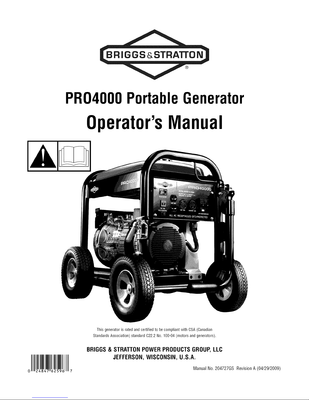
PRO4000PortableGenerator
Operator'sManual
This generator is rated and certified to becompliant with CSA (Canadian
Standards Association) standard 022.2 No. 100-04 (motors and generators).
BRIGGS & STRATTON POWER PRODUCTS GROUP, LLC
JEFFERSON, WISCONSIN, U.S.A.
Manual No. 204727GS
RevisionA (04/29/2009)
Thankyou for purchasing this quality-built Briggs & Stratton generator.We are pleasedthat you've placedyour confidencein
the Briggs& Stratton brand. When operated and maintained according to the instructions in this manual,your Briggs &
Stratton generatorwill provide many years of dependableservice.
Thismanualcontainssafety information to makeyou aware of the hazardsand risks associatedwith generators and how to
avoid them. This generatoris designed and intendedonly for supplying electrical powerfor operating compatibleelectrical
lighting, appliances,tools and motor loads, and is not intendedfor anyother purpose. It is important that you readand
understand these instructions thoroughly before attempting to start or operatethis equipment. Save these instructionsfor
future reference.
Thisgenerator requiresfinal assemblybeforeuse. Referto the Assemb/ysection of this manualfor instructions on final
assembly procedures. Follow the instructions completely.
Whereto FindUs
You never have to look far to find Briggs & Stratton support and service for your generator. Consultyour Yellow Pages.There
are over 30,000 Briggs & Stratton authorized service dealersworldwide who provide quality service. You canalso contact
Briggs & Stratton Customer Service by phone at (800) 743-4115, or on the Internet at BRIGGSandSTRATTON.COM.
Generator
Model Number
Revision
Serial Number
Engine
Model Number
Type Number
Code Number
DatePurchased
Briggs & Stratton PowerProducts Group, LLC
900 North Parkway
Jefferson, WI 53549
III
III
III III III
Copyright © 2009. All rights reserved.Nopart of this material
may be reproducedor transmitted in anyform by any means
without the expresswritten permission of Briggs & Stratton
Power Products Group, LLC.
2 BRIGGSandSTRATTON.COIVl
Tableof Contents
Operator Safety ................................. 4
Equipment Description......................................... 4
Important Safety Information.................................... 4
Assembly ..................................... 7
UnpackGenerator ............................................ 7
Shipment Contents ........................................... 7
Install Wheel Kit.............................................. 7
Add Engine Oil............................................... 8
Add Fuel.................................................... 8
System Ground .............................................. 9
Connectingto aBuilding's Electrical System........................ 9
GeneratorLocation ........................................... 9
FeaturesandControls............................ 10
Cord Sets and Receptacles.................................... 11
Ground Fault Protection....................................... 12
Operation .................................... 13
Starting the Engine .......................................... 13
ConnectingElectrical Loads.................................... 13
Stopping the Engine.......................................... 14
OperatingAutomatic Idle Control................................ 14
Oil PressureShutdown ....................................... 14
Charginga Battery........................................... 14
ColdWeatherOperation....................................... 15
Don't OverloadGenerator ..................................... 16
Maintenance .................................. 17
MaintenanceSchedule........................................ 17
GeneratorMaintenance....................................... 17
FuelValveMaintenance....................................... 18
Engine Maintenance.......................................... 18
Storage ................................................... 21
Troubleshooting ................................ 22
Schematic ................................................. 23
Wiring Diagram ............................................. 24
Warranties .................................... 25
Emissions Control System Warranty ............................. 25
GeneratorOwnerWarranty .................................... 27
Specifications ................................. 28
Product Specifications........................................ 28
Common Service Parts ....................................... 28
Frangais Espa_ol
OperatorSafety
Equipment Description
Readthis manual carefully and becomefamiliar
...... with your generator. Knowits applications, its
limitationsand any hazardsinvolved.
Thegeneratoris anengine-driven, revolvingfield, alternating
current (AC) generator. It was designedto supply electrical
power for operatingcompatible electricallighting, appliances,
tools and motor loads.Thegenerator's revolving field is
driven at about3,600 rpm by a single-cylinderengine.
This generator incorporates GFCI(Ground Fault Circuit
Interrupter) outlet protection andhas its neutral bonded to
ground to comply to OSHAinspections on job sites. This
generatorwill not function when connectedto a 2 pole
transfer switch sincethe home or building main breaker box
also has a neutral bondedto ground. When both the
generator andthe home or building breakerbox contains a
neutral bonded to ground, the generatorsGFCIwill open and
no outlets will function.
_i, WARNING Removingthe neutral bond could resultin
_1_ death, bodily injury and/or propertydamage.
m,
• DONOTremovetheneutralbond.
Important Safety Information
Themanufacturer cannot possibly anticipateevery possible
circumstance that might involve a hazard.Thewarnings in
this manual, and the tags and decals affixedto the unit are,
therefore, not all-inclusive. Ifyou usea procedure,work
method or operating technique that the manufacturer does
not specifically recommend, you must satisfy yourself that it
is safe for you andothers. You must also makesure that the
procedure, work method or operating technique that you
choose does not renderthe generator unsafe.
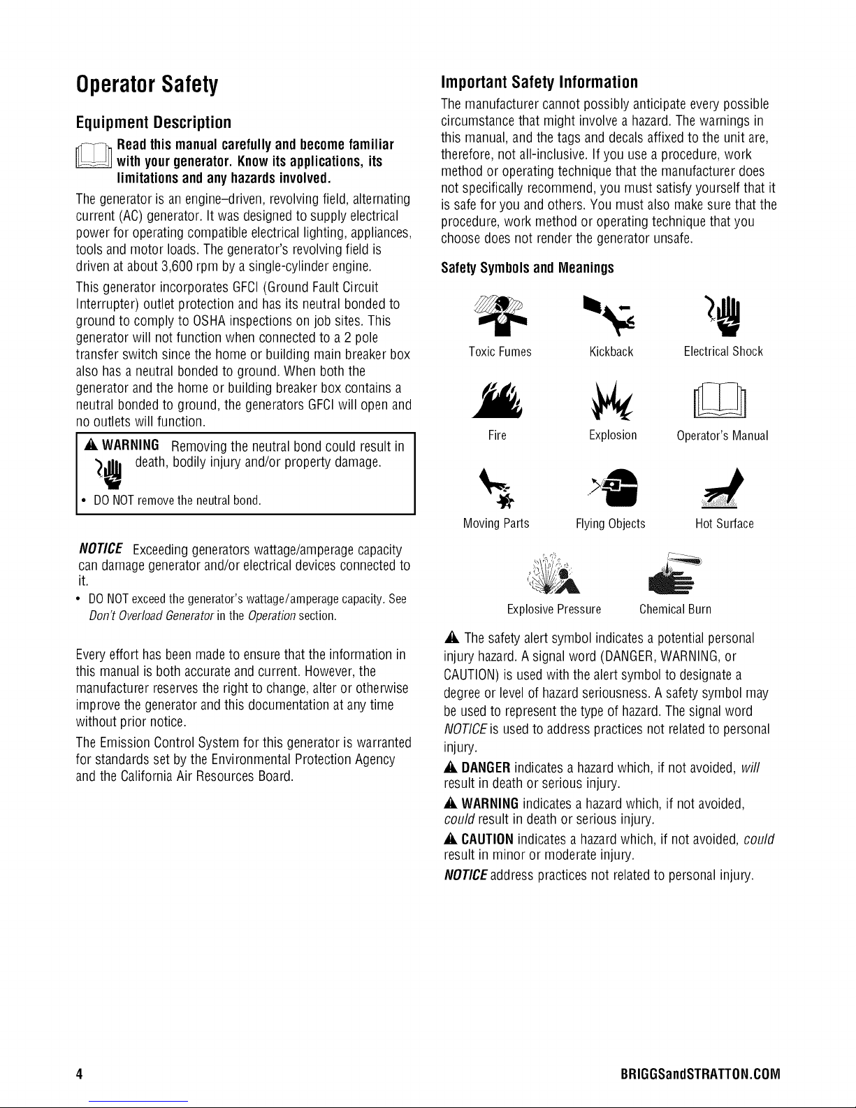
SafetySymbolsand Mleanings
Toxic Fumes Kickback ElectricalShock
Fire Explosion Operator'sManual
Moving Parts FlyingObjects Hot Surface
NOTICE Exceedinggeneratorswattage/amperagecapacity
candamagegenerator and/or electrical devices connectedto
it.
• DONOTexceedthegenerator'swattage/amperagecapacity.See
Don'tOverloadGeneratorinthe Operationsection.
Everyeffort hasbeen madeto ensurethat the information in
this manual is both accurateand current. However,the
manufacturer reservesthe right to change,alter or otherwise
improve the generator and this documentation at anytime
without prior notice.
The EmissionControl System for this generator is warranted
for standardsset by the Environmental Protection Agency
and the California Air ResourcesBoard.
,lib
ExplosivePressure
,A Thesafety alert symbol indicates a potential personal
injury hazard.A signal word (DANGER,WARNING,or
CAUTION)is usedwith the alert symbol to designatea
degreeor levelof hazardseriousness.A safety symbol may
be usedto representthe type of hazard.Thesignal word
NOTICEis usedto address practicesnot relatedto personal
injury.
_i, DANGER indicates a hazardwhich, if not avoided, will
result in deathor serious injury.
_i, WARNINGindicates a hazardwhich, if not avoided,
could result indeath or serious injury.
_i, CAUTIONindicates ahazardwhich, if not avoided, could
result in minor or moderate injury.
NOTICEaddress practices not related to personal injury.
ChemicalBurn
4 BRIGGSandSTRATTON.COIVl
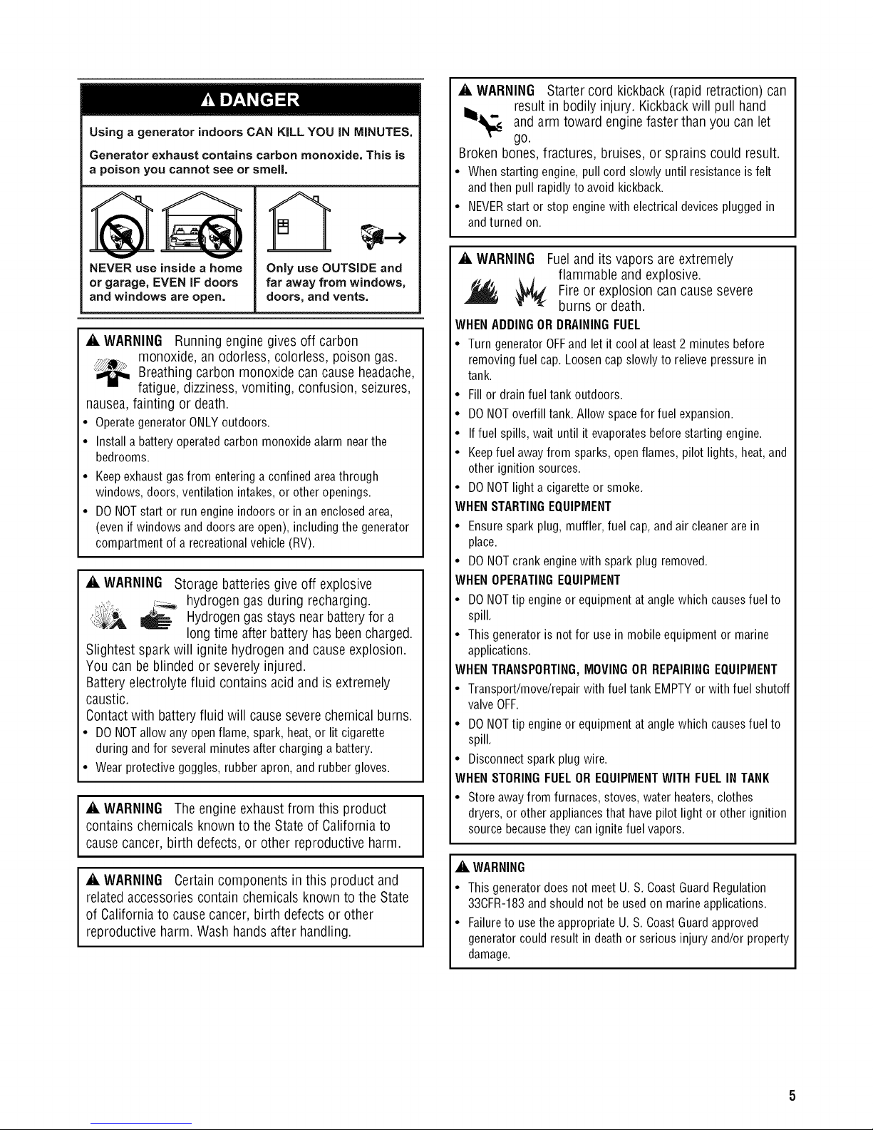
Using a generator indoors CAN KiLL YOU iN MINUTES,
Generator exhaust contains carbon monoxide, This is
a poison you cannot see or smell,
A
_i, WARNING Starter cord kickback (rapid retraction) can
result in bodily injury. Kickback will pull hand
_ and arm toward engine faster than you can let
go.
Broken bones, fractures, bruises, or sprains could result.
• When starting engine, pull cord slowly until resistanceisfelt
andthen pull rapidlyto avoid kickback.
• NEVERstart or stop enginewith electricaldevices plugged in
andturned on.
V V
NEVER use inside a home
or garage, EVEN iF doors
and windows are open,
_i, WARNING Running engine gives off carbon
monoxide, an odorless, colorless, poison gas.
Breathing carbon monoxide can cause headache,
fatigue, dizziness, vomiting, confusion, seizures,
nausea, fainting or death.
• Operategenerator ONLYoutdoors.
• Install a battery operatedcarbon monoxidealarm nearthe
bedrooms.
• Keepexhaustgas from entering a confinedareathrough
windows, doors,ventilation intakes, or other openings.
• DO NOTstart or run engine indoors or in an enclosedarea,
(even if windows anddoors are open), including the generator
compartment of arecreational vehicle (RV).
Only use OUTSIDE and
far away from windows,
doors, and vents,
_i, WARNING Storage batteriesgive off explosive
_,il;,_ ,,-_.._.hydrogen gas during recharging.
,t_,,_._,, _ Hydrogengasstays nearbatteryfor a
long time after battery has beencharged.
Slightest spark will ignite hydrogen and cause explosion.
You can be blinded or severelyinjured.
Batteryelectrolytefluid contains acid and is extremely
caustic.
Contactwith batteryfluid will causeseverechemicalburns.
• DONOTallowanyopenflame,spark,heat,orlitcigarette
duringandfor severalminutesaftercharginga battery.
• Wearprotectivegoggles,rubberapron,andrubbergloves.
A, WARNING Theengineexhaustfrom this product
contains chemicals known to the State of Californiato
causecancer, birth defects,or other reproductive harm.
_i, WARNING Certain components in this product and
relatedaccessoriescontain chemicals known to the State
of Californiato causecancer, birth defectsor other
reproductive harm. Washhands after handling.
_i, WARNING Fuel and its vapors are extremely
flammable and explosive.
Fire or explosion can cause severe
burns or death.
WHENADDINGOR DRAININGFUEL
• Turn generator OFFand let it coolat least2 minutes before
removing fuel cap. Loosen cap slowly to relievepressure in
tank.
• Fill or drain fuel tank outdoors.
• DONOToverfill tank. Allow spacefor fuel expansion.
• Iffuel spills,wait until it evaporatesbefore starting engine.
• Keepfuel awayfrom sparks, open flames, pilot lights, heat, and
other ignition sources.
• DONOTlight a cigaretteor smoke.
WHENSTARTINGEQUIPMENT
• Ensure spark plug, muffler, fuel cap, and air cleanerare in
place.
• DO NOTcrank enginewith spark plug removed.
WHENOPERATINGEQUIPMENT
• DONOTtip engine or equipmentat angle which causesfuel to
spill.
• This generator is not for use in mobile equipment or marine
applications.
WHENTRANSPORTING,MOVINGOR REPAIRINGEQUIPMENT
• Transport/move/repair with fuel tank EMPTYor with fuel shutoff
valveOFF.
• DONOTtip engine or equipmentat angle which causesfuel to
spill.
• Disconnectspark plug wire.
WHENSTORINGFUELOR EQUIPMENTWITH FUEL IN TANK
• Store away from furnaces, stoves, water heaters,clothes
dryers, or otherappliancesthat havepilot light or other ignition
source becausethey can ignite fuel vapors.
A WARNING
• This generator does notmeet U. S. CoastGuardRegulation
33CFR-183and should not beusedon marineapplications.
• Failureto usethe appropriate U. S.CoastGuard approved
generator could result in deathor serious injury and/or property
damage.
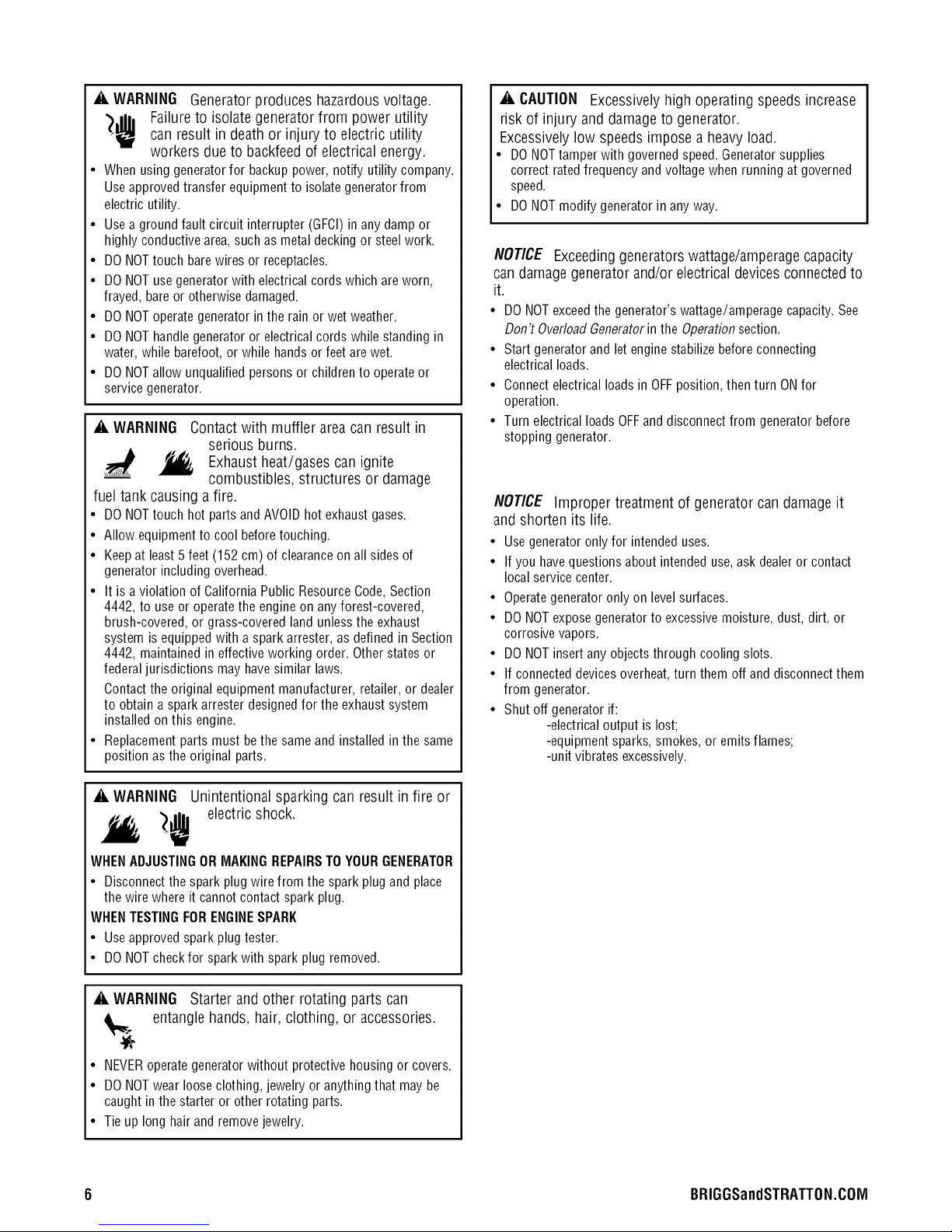
_i, WARNING Generator produces hazardous voltage.
'),111, Failure to isolate generator from power utility
can result in death or injury to electric utility
workers due to backfeed of electrical energy.
• When using generator for backup power, notify utility company.
Use approvedtransfer equipment to isolategeneratorfrom
electric utility.
• Use a ground fault circuit interrupter (GFCI)in any damp or
highly conductivearea,such as metal decking or steel work.
• DO NOTtouch barewires or receptacles.
• DO NOTuse generator with electrical cords which areworn,
frayed, bareor otherwisedamaged.
• DO NOToperate generator in the rain or wet weather.
• DO NOThandle generator or electricalcords while standing in
water, while barefoot,or while hands or feet are wet.
• DO NOTallow unqualified personsor children to operate or
servicegenerator.
_i, WARNING Contact with muffler area can result in
serious burns.
Exhaust
combustibles, structures or damage
fuel tank causing a fire.
• DO NOTtouch hot parts andAVOID hot exhaust gases.
• Allow equipment to cool before touching.
• Keepat least5 feet (152 cm) of clearanceon all sidesof
generator including overhead.
• It is aviolation of California Public Resource Code,Section
4442, to use or operate the engineon any forest-covered,
brush-covered, or grass-covered land unlessthe exhaust
system is equipped with aspark arrester, as defined in Section
4442, maintained in effective working order. Otherstates or
federal jurisdictions may have similar laws.
Contactthe original equipment manufacturer, retailer, or dealer
to obtain a sparkarrester designed for the exhaust system
installed on this engine.
• Replacement parts must bethe same and installed inthe same
position asthe original parts.
heat/gases can ignite
_i, CAUTION Excessively high operating speeds increase
risk of injury and damage to generator.
Excessively low speeds impose a heavy load.
• DO NOTtamper with governedspeed. Generatorsupplies
correct rated frequency and voltage when running at governed
speed.
• DO NOTmodify generator in any way.
NOTICE Exceeding generators wattage/amperage capacity
can damage generator and/or electrical devices connected to
it.
• DO NOTexceedthe generator's wattage/amperage capacity. See
Don't OverloadGeneratorin the Operationsection.
• Start generator and let engine stabilize beforeconnecting
electrical loads.
• Connectelectrical loadsin OFFposition, thenturn ONfor
operation.
• Turn electrical loads OFFand disconnect from generator before
stopping generator.
NOTICE Improper treatment of generator can damage it
and shorten its life.
• Use generator only for intended uses.
• If you havequestions about intended use,ask dealeror contact
local service center.
• Operategenerator only on level surfaces.
• DO NOTexpose generator to excessivemoisture, dust, dirt, or
corrosive vapors.
• DO NOTinsert any objects through cooling slots.
• If connected devicesoverheat, turn them off and disconnect them
from generator.
• Shut off generator if:
-electrical output is lost;
-equipment sparks, smokes, or emits flames;
-unit vibrates excessively.
_i, WARNING Unintentional sparking can result in fire or
_ electric shock.
WHENADJUSTINGOR MAKINGREPAIRSTO YOURGENERATOR
• Disconnectthe spark plug wire from the spark plug and place
the wire where it cannot contact spark plug.
WHENTESTINGFORENGINESPARK
• Use approved spark plug tester.
• DO NOTcheck for spark with spark plug removed.
_i, WARNING Starter and other rotating parts can
entangle hands, hair, clothing, or accessories.
• NEVERoperategeneratorwithout protective housing or covers.
• DO NOTwear looseclothing, jewelry or anythingthat may be
caught in thestarter or other rotating parts.
• Tie up long hairand removejewelry.
6 BRIGGSandSTRATTON.COIVI
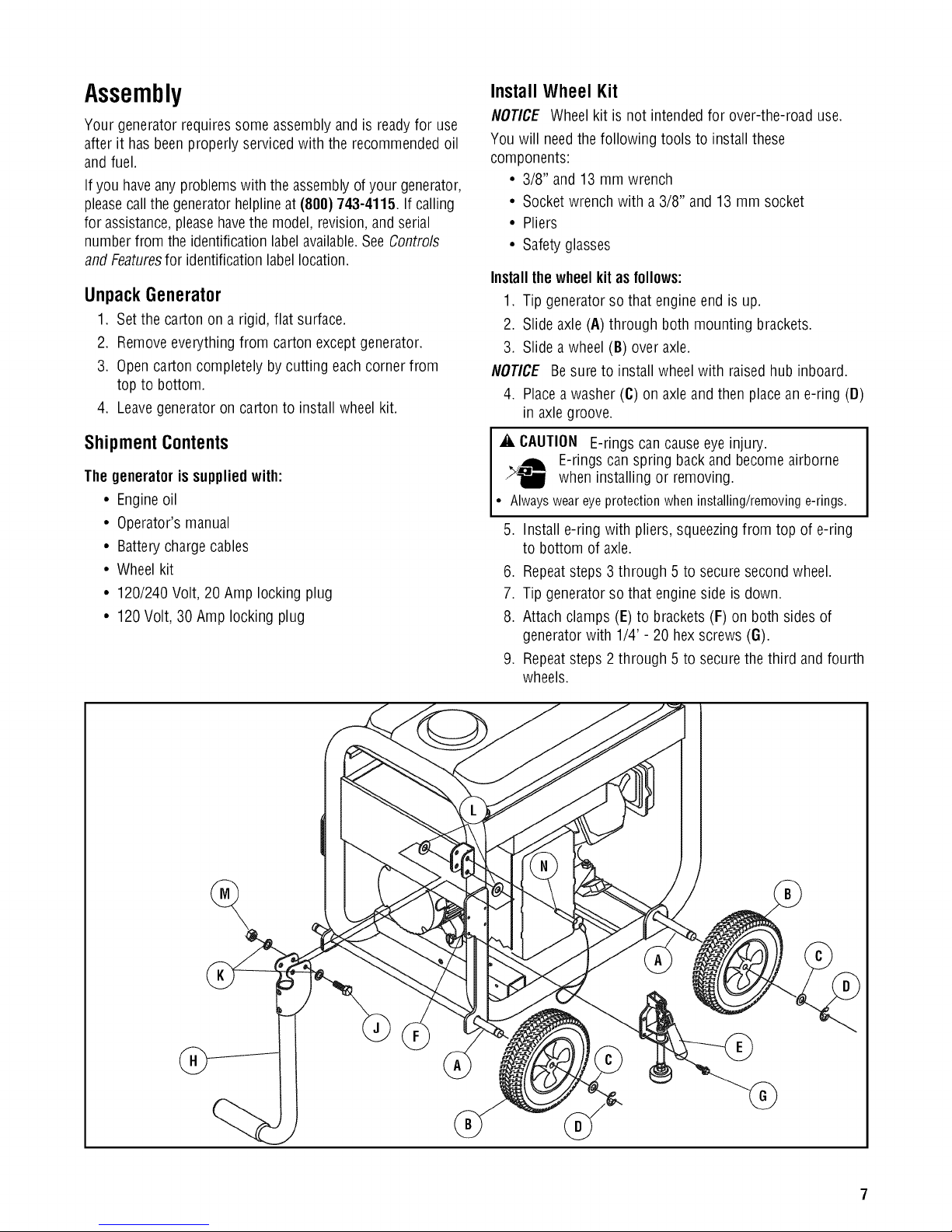
Assembly
Your generator requiressome assembly and is readyfor use
after it hasbeen properly servicedwith the recommended oil
and fuel.
If you haveany problemswith the assemblyof your generator,
pleasecall the generator helplineat (800)743-4115. If calling
for assistance,pleasehavethe model,revision,andserial
numberfrom the identificationlabelavailable.SeeControls
and Featuresfor identificationlabel location.
UnpackGenerator
1. Setthe carton on a rigid, flat surface.
2. Removeeverything from carton except generator.
3. Opencarton completely by cutting each corner from
top to bottom.
4. Leavegeneratoron cartonto install wheel kit.
Install Wheel Kit
NOTICE Wheel kit is not intended for over-the-road use.
You will needthe following tools to install these
components:
• 3/8" and 13 mmwrench
• Socketwrench with a 3/8" and 13mm socket
• Pliers
• Safetyglasses
Installthewheelkit asfollows:
1. Tip generatorso that engineend is up.
2. Slide axle (A) through both mounting brackets.
3. Slide a wheel (B) over axle.
NOTICE Besure to install wheelwith raised hub inboard.
4. Placea washer (C) on axleandthen placean e-ring (D)
in axle groove.
Shipment Contents
The generatoris suppliedwith:
• Engineoil
• Operator's manual
• Batterycharge cables
• Wheelkit
• 120/240 Volt, 20 Amp locking plug
• 120Volt, 30Amp locking plug
_i, CAUTION E-rings can causeeye injury.
E-rings can spring back and become airborne
when installing or removing.
• Alwaysweareyeprotectionwheninstalling/removinge-rings.
5. Install e-ring with pliers, squeezingfrom top of e-ring
to bottom of axle.
6. Repeatsteps 3 through 5 to securesecondwheel.
7. Tip generatorso that engineside is down.
8. Attach clamps (E) to brackets (F) on both sides of
generatorwith 1/4' - 20 hexscrews (G).
9. Repeatsteps 2 through 5 to securethe third and fourth
wheels.
10.Attachhandle(H)tobracketongeneratorframeas
shown,witha50mmcapscrew(J),flatwashers(K),
nylonwashers(L),andM8locknut(M).
NOTICE DO NOTovertighten. Handlemust beable to move
up and down freely.
11. Return generator to normal operating position (resting
on wheels).
12. To apply brakes,push down firmly on handle of both
clamps until it locks in the down position andengages
the wheels.
NOTICE The generator is designedto be used on level
surfaces.
13. Loop handlepin (N) on generatorframe just above
handle bracket.
14. Raise handleand insert handlepin to movegenerator.
15. To releasebrakes,pull up on handle of both clamps
until it locks in the up position.
Add Engine Oil
1. Placegeneratoron a flat, levelsurface.
2. Cleanarea around oil fill andremoveyellow oil fill cap.
3. Using oil funnel (optional), slowly pour contents of
provided oil bottle into oil fill opening.
NOTICE Improper treatment of generator can damage it
and shorten its life.
• DO NOTattempt to crank or start the engine beforeit has been
properly servicedwith the recommended oil. This may result in an
enginefailure.
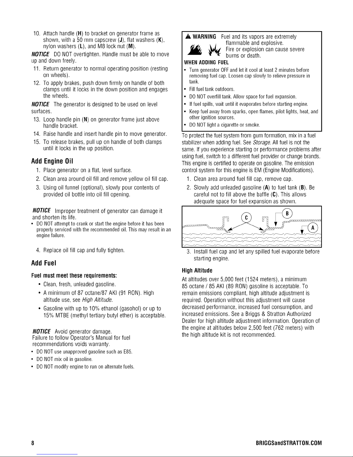
_i, WARNING Fueland its vapors are extremely
flammable and explosive.
_, _ Fire or explosion can causesevere
burns or death.
WHENADDINGFUEL
• Turn generator OFFand let it cool at least2 minutes before
removing fuel cap. Loosen cap slowly to relievepressure in
tank.
• Fill fuel tank outdoors.
• DONOToverfill tank. Allow spacefor fuel expansion.
• Iffuel spills,wait until it evaporatesbefore starting engine.
• Keepfuel awayfrom sparks, open flames, pilot lights, heat, and
other ignition sources.
• DONOTlight a cigaretteor smoke.
To protectthe fuelsystemfrom gum formation, mix ina fuel
stabilizerwhen addingfuel. SeeStorage.All fuel is not the
same.Ifyou experiencestartingor performanceproblems after
usingfuel,switch to adifferentfuel provideror changebrands.
This engineis certified to operateon gasoline.Theemission
control systemfor this engineis EM(EngineModifications).
1. Cleanarea around fuel fill cap,remove cap.
2. Slowly addunleadedgasoline (A) to fuel tank (B). Be
careful not to fill abovethe baffle (C). This allows
adequatespace for fuel expansion as shown.
4. Replaceoil fill cap and fully tighten.
Add Fuel
Fuel must meet theserequirements:
• Clean,fresh, unleadedgasoline.
• A minimum of 87 octane/87AKI (91 RON).High
altitude use, seeHigh Altitude.
• Gasolinewith up to 10% ethanol (gasohol) or up to
15% MTBE(methyl tertiary butyl ether) is acceptable.
NOTICE Avoid generatordamage.
Failureto follow Operator's Manualfor fuel
recommendations voids warranty.
• DONOTuseunapprovedgasolinesuchasE85.
• DONOTmixoilin gasoline.
• DONOTmodifyengineto runonalternatefuels.
3. Install fuel capand let any spilled fuel evaporatebefore
starting engine.
High Altitude
At altitudes over 5,000 feet (1524 meters), a minimum
85 octane/ 85 AKI (89 RON)gasoline is acceptable.To
remainemissions compliant, high altitude adjustment is
required.Operationwithout this adjustment will cause
decreasedperformance, increasedfuel consumption, and
increasedemissions. Seea Briggs & Stratton Authorized
Dealerfor high altitude adjustment information. Operation of
the engine at altitudes below 2,500 feet (762 meters) with
the high altitude kit is not recommended.
8 BRIGGSandSTRATTON.COIVl
SystemGround
Thegenerator hasa system ground that connectsthe
generatorframe components to the ground terminals onthe
ACoutput receptacles.Thesystem ground is connected to
the ACneutral wire (the neutral is bonded to the generator
frame).
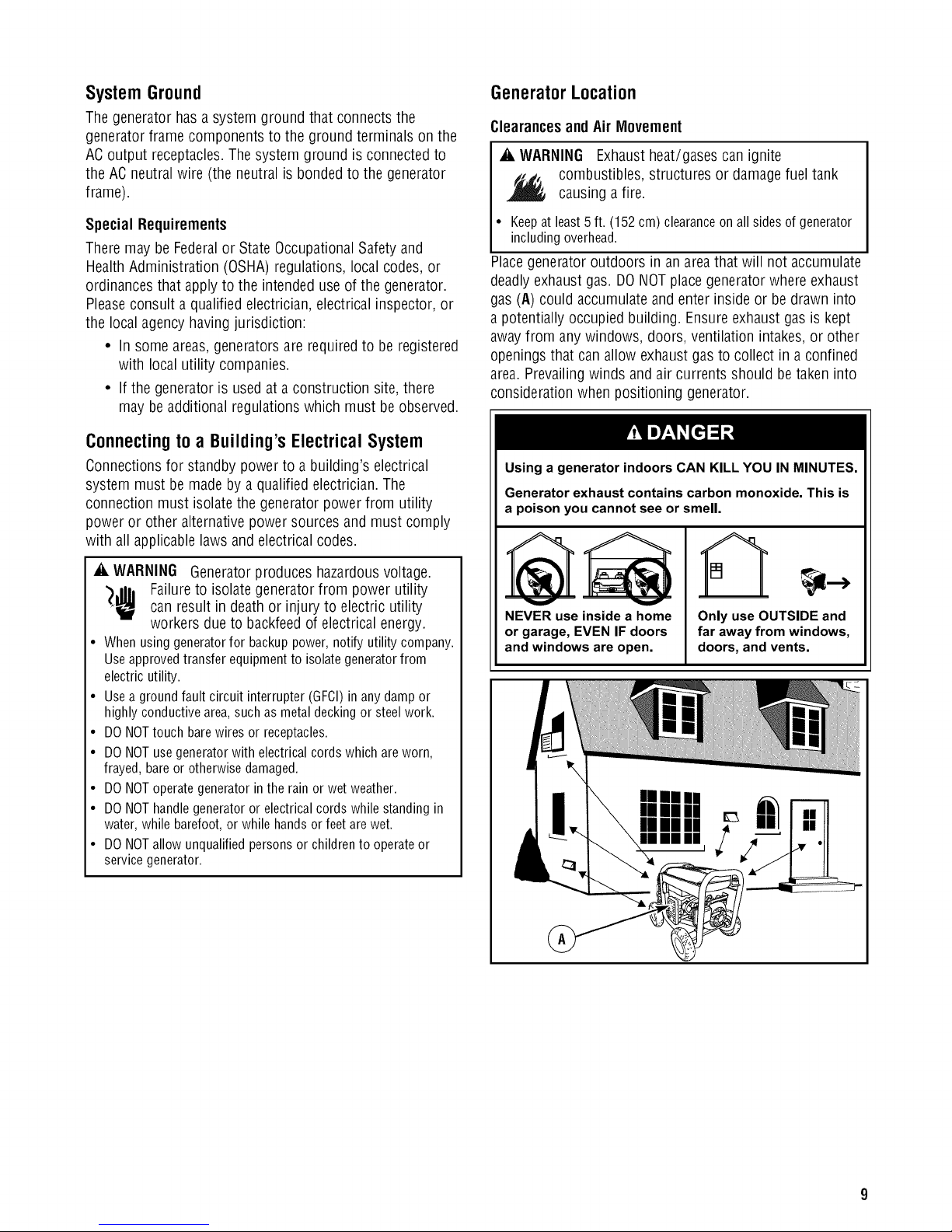
GeneratorLocation
Clearancesand Air Movement
_i, WARNING Exhaustheat/gases can ignite
combustibles, structures or damagefuel tank
causing a fire.
Special Requirements
Theremay be Federalor State OccupationalSafety and
Health Administration (OSHA)regulations, local codes, or
ordinances that applyto the intended useof the generator.
Pleaseconsult a qualified electrician, electrical inspector, or
the local agency having jurisdiction:
• In some areas,generators are requiredto be registered
with local utility companies.
• Ifthe generator is usedat a construction site, there
may be additional regulations which must be observed.
Connecting to a Building's Electrical System
Connectionsfor standby powerto a building's electrical
system must be made by a qualified electrician. The
connection must isolate the generator powerfrom utility
power or other alternativepower sources andmust comply
with all applicablelaws andelectrical codes.
A, WARNING Generatorproduces hazardousvoltage.
')Jib Failureto isolate generatorfrom power utility
can result in deathor injury to electric utility
workers due to backfeedof electrical energy.
• Whenusinggeneratorfor backuppower,notifyutilitycompany.
Useapprovedtransferequipmentto isolategeneratorfrom
electricutility.
• Useagroundfaultcircuitinterrupter(GFCI)in anydampor
highlyconductivearea,suchas metaldeckingor steelwork.
• DONOTtouchbarewiresor receptacles.
• DONOTusegeneratorwithelectricalcordswhichareworn,
frayed,bareorotherwisedamaged.
• DONOToperategeneratorintherainorwetweather.
• DONOThandlegeneratoror electricalcordswhilestandingin
water,whilebarefoot,or whilehandsorfeetarewet.
• DONOTallowunqualifiedpersonsor childrento operateor
servicegenerator.
• Keepatleast5 ft. (152cm) clearanceonall sidesof generator
includingoverhead.
Placegenerator outdoors in an areathat will not accumulate
deadlyexhaust gas. DONOTplace generatorwhere exhaust
gas (A) could accumulate and enter inside or be drawn into
a potentially occupied building. Ensureexhaustgas is kept
awayfrom any windows, doors, ventilation intakes, or other
openings that canallow exhaust gasto collect in a confined
area.Prevailingwinds and air currents should betaken into
consideration when positioning generator.
Using a generator indoors CAN KILL YOU IN MINUTES.
Generator exhaust contains carbon monoxide. This is
a poison you cannot see or smell.
,A
B
V V
NEVER use insidea home
or garage, EVENIF doors
and windowsare open.
Only use OUTSIDE and
far away from windows,
doors, and vents.
1
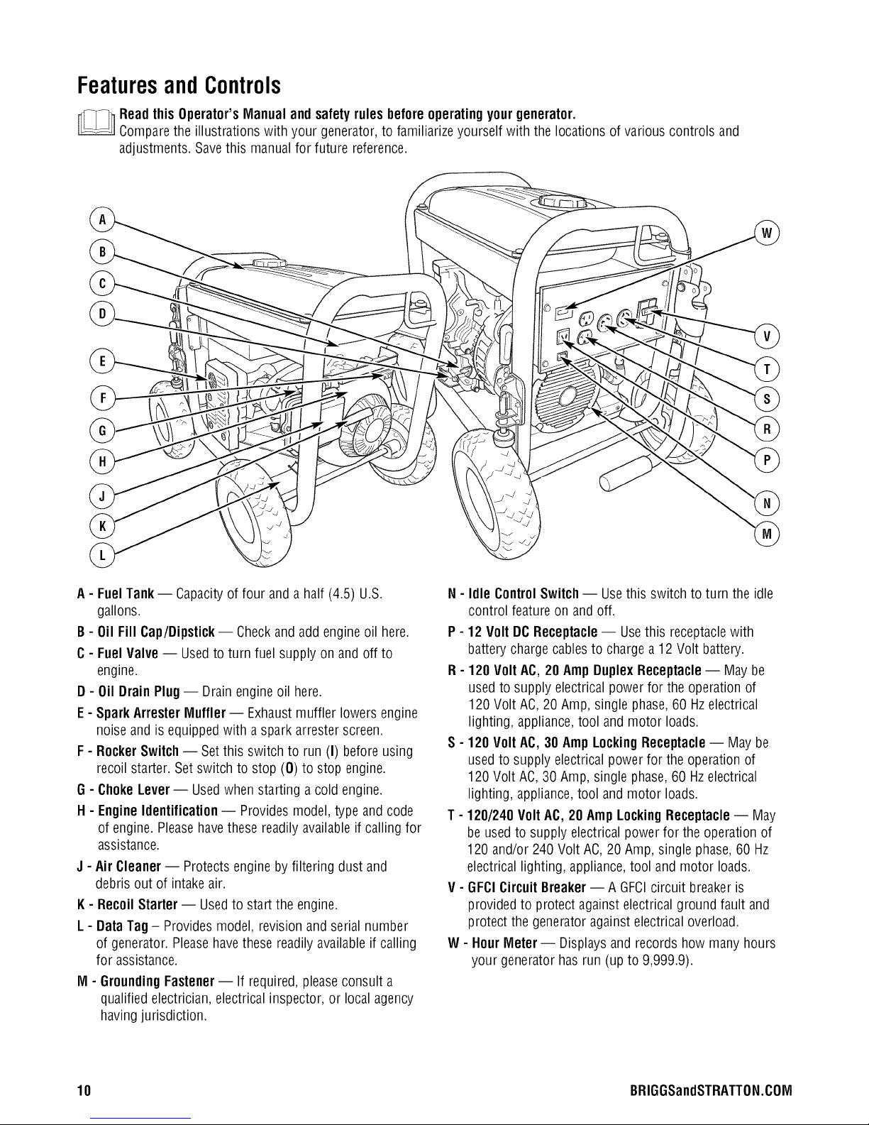
FeaturesandControls
Readthis Operator'sManualand safetyrules beforeoperatingyourgenerator.
Comparethe illustrations with your generator,to familiarize yourself with the locations of various controls and
adjustments. Savethis manual for future reference.
A- FuelTank -- Capacityof four and a half (4.5) U.S.
gallons.
B- Oil Fill Cap/Dipstick-- Checkand add engineoil here.
C- Fuel Valve-- Usedto turn fuel supply on and off to
engine.
D - Oil DrainPlug -- Drainengine oil here.
E - Spark ArrestorMuffler -- Exhaust muffler lowers engine
noise and is equipped with a spark arrestor screen.
F - Rocker Switch -- Set this switch to run (I) before using
recoil starter. Setswitch to stop (0) to stop engine.
G - ChokeLever- Usedwhen starting a cold engine.
H - Engine Identification -- Provides model, type and code
of engine. Pleasehavethesereadily availableif calling for
assistance.
J - Air Cleaner-- Protectsengine by filtering dust and
debris out of intake air.
K- Recoil Starter -- Usedto start the engine.
L - Data Tag - Provides model, revision and serial number
of generator. Pleasehavethese readilyavailableif calling
for assistance.
M - GroundingFastener-- If required, pleaseconsult a
qualified electrician, electrical inspector, or local agency
havingjurisdiction.
N - Idle ControlSwitch -- Usethis switch to turn the idle
control feature on andoff.
P - 12 Volt DC Receptacle -- Usethis receptaclewith
batterycharge cablesto chargea 12Volt battery.
R - 120Volt AC, 20 Amp DuplexReceptacle-- May be
usedto supply electrical power for the operation of
120 Volt AC,20 Amp, single phase,60 Hzelectrical
lighting, appliance,tool and motor loads.
S - 120 Volt AC,30 AmpLockingReceptacle -- May be
usedto supply electrical power for the operation of
120 Volt AC, 30 Amp, single phase, 60 Hzelectrical
lighting, appliance,tool and motor loads.
T - 120/240 Volt AC,20 AmpLockingReceptacle-- May
be usedto supply electrical power for the operation of
120 and/or 240Volt AC,20 Amp,single phase,60 I-Iz
electrical lighting, appliance,tool and motor loads.
V - GFClCircuitBreaker-- A GFCIcircuit breakeris
providedto protect against electricalground fault and
protect the generatoragainst electrical overload.
W - Hour Meter- Displays and records how many hours
your generatorhas run (up to 9,999.9).
10 BRIGGSandSTRATTON.COM
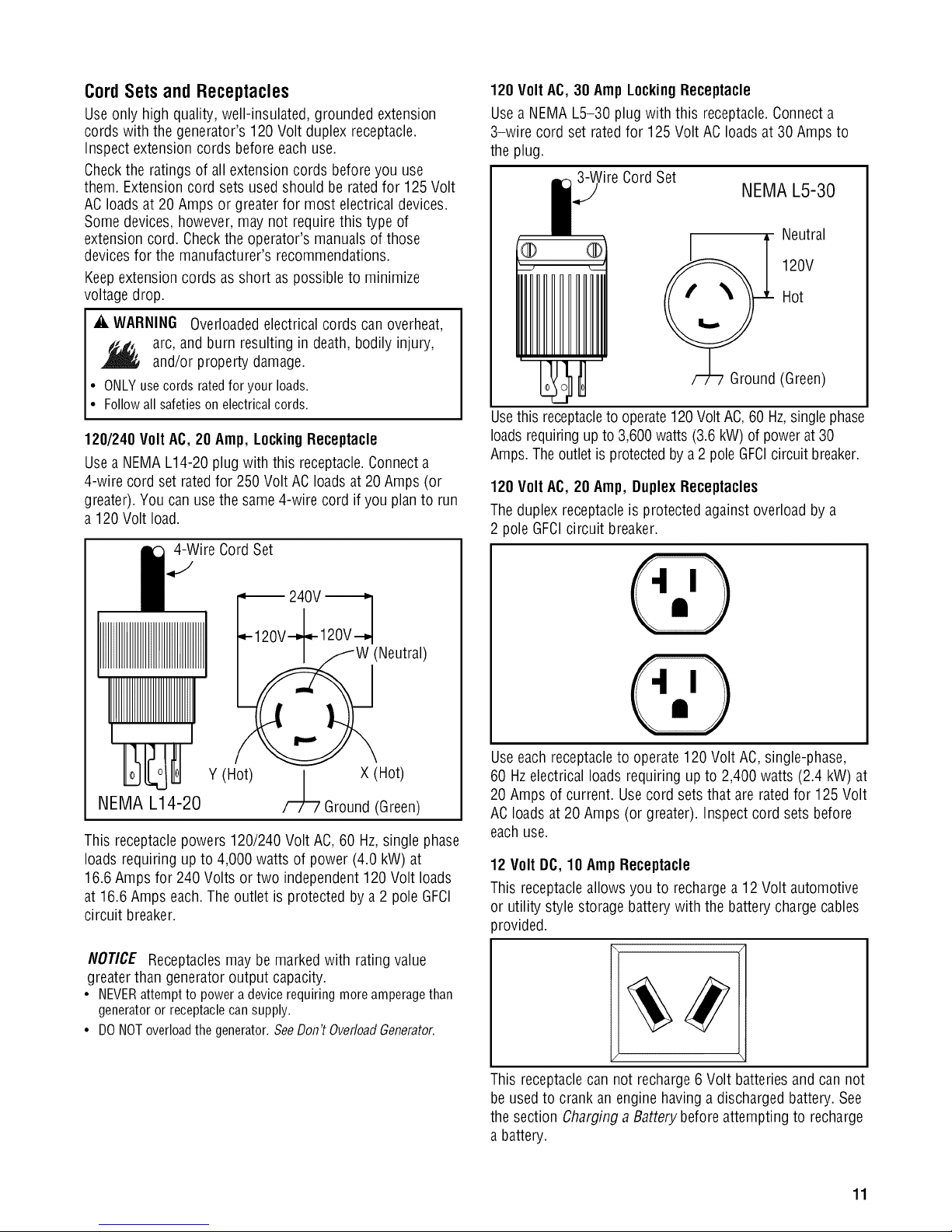
CordSetsandReceptacles
Use only high quality, well-insulated, grounded extension
cords with the generator's 120 Volt duplex receptacle.
Inspect extension cords before eachuse.
Checkthe ratings of all extensioncords beforeyou use
them. Extensioncord sets usedshould be rated for 125 Volt
ACloads at 20 Amps or greaterfor most electrical devices.
Somedevices,however, may not require this type of
extension cord. Checkthe operator's manuals of those
devicesfor the manufacturer's recommendations.
Keepextension cords asshort aspossible to minimize
voltage drop.
120 Volt AC, 30 Amp LockingReceptacle
Usea NEMA L5-30 plugwith this receptacle.Connecta
3-wire cord set ratedfor 125 Volt ACloads at 30 Amps to
the plug.
_'ireCord Set
NEMA L5-30
Neutral
® ®
120V
Hot
_i, WARNING Overloadedelectrical cords can overheat,
arc, and burn resulting in death, bodily injury,
and/or property damage.
• ONLYusecordsratedfor yourloads.
• Followallsafetiesonelectricalcords.
120/240 Volt AC, 20 Amp, LockingReceptacle
Use a NEMAL14-20 plugwith this receptacle.Connecta
4-wire cord set rated for 250 Volt AC loadsat 20 Amps (or
greater). You can usethe same4-wire cord if you planto run
a 120 Volt load.
I 4-Wire CordSet
(Neutral)
Y (Hot)
NEMA L14-20
This receptaclepowers 120/240 Volt AC, 60 Hz,single phase
loads requiring up to 4,000 watts of power (4.0 kW) at
16.6 Amps for 240 Volts or two independent 120 Volt loads
at 16.6 Amps each. Theoutlet is protected by a2 pole GFCI
circuit breaker.
F7L7 X (Hot)
Ground (Green)
II11111111111
(Green)
Usethis receptacleto operate120 VoltAC,60 Hz,singlephase
loadsrequiringup to 3,600watts (3.6kW)of powerat30
Amps.Theoutlet is protectedby a 2 pole GFCIcircuit breaker.
120 Volt AC, 20 Amp, DuplexReceptacles
Theduplex receptacleis protected against overload by a
2 pole GFCIcircuit breaker.
Useeachreceptacleto operate 120 Volt AC, single-phase,
60 Hz electricalloads requiring upto 2,400 watts (2.4 kW) at
20 Amps of current. Usecord sets that are ratedfor 125 Volt
ACloads at 20 Amps (or greater). Inspect cord sets before
eachuse.
12 Volt DC,10 AmpReceptacle
This receptacleallows you to rechargea 12 Volt automotive
or utility style storagebatterywith the battery charge cables
provided.
NOTICE Receptacles may be marked with rating value
greater than generator output capacity.
• NEVERattempt to power adevice requiring moreamperagethan
generator or receptacle can supply.
• DONOToverloadthe generator. SeeDon't OverloadGenerator.
This receptaclecan not recharge6 Volt batteriesand can not
be usedto crank anengine having adischarged battery. See
the section Charginga Batterybefore attempting to recharge
a battery.
11
Ground Fault Protection
This unit is equippedwith a Ground Fault Circuit Interrupter
(GFCI).This device meets applicablefederal, stateand local
codes.
The GFCIprotects against electrical shockthat may be
caused if your body becomes a pathwhich electricity travels
to reachground. This could happenif you touch a"Live"
applianceor wire, or aretouching plumbing or other
materials that connectto the ground.
When protected by a GFCI,one may still feel a shock, but the
GFCIshould cut current off quickly enough so that aperson
in normal healthshould not suffer anyserious electrical
injury.
_k WARNING Generator produces hazardous
_ voltage/current.
• TheGFCIwill not protect you againstthe following situations:
-Line-to-line shocks;
-Current overloadsor line-to-line short circuits.
• Thefuse or circuit breakeratthe control panel must provide
such protection.
DuringGeneratorUse
If circuit breakertrips during use,it usually indicates faulty
electrical equipment or cords. However,test the circuit
breakeras follows;
1. Disconnect loads, reset and test circuit breakeras
described earlier. Let generator runwithout any loads
for 1 minute.
_k CAUTION If circuit breaker trips in the 1 minute
period:
• DONOTusegenerator.
• Calla Briggs& StrattonPowerProductsservicecenter.
,
If circuit breakertests correctly, the electrical
equipment or extension cords may befaulty. Replace
faulty electrical equipment andcords beforefurther
use.
A. CAUTION If circuit breaker tests correctly:
• Havequalified personnel checkall electricalequipment and
cords for any defects.
• Replaceelectricalequipment and cords or taketo a qualified
repair center.
TestGFCICircuit Breaker
Testyour GFCIcircuit breaker every month, as follows:
1. While generator is running, push white "Test" button.
Thecircuit breakershould trip (handle will move to
approximate center position), which will disconnect
power to outlets.
_k CAUTION If circuit breaker does not trip:
• DONOTusegenerator.
• Calla Briggs& StrattonPowerProductsservicecenter.
2. If handlemoves to center, resetcircuit breakerby
firmly moving handleto "Off" (down) position, then to
"On" (up) position.
_k WARNING Generator produces hazardous
_1_ voltage/current.
• DO NOTtouch barewires or receptacles.
• DO NOTuse generator with electrical cords which areworn,
frayed,bare or otherwisedamaged.
• DO NOToperate generator in the rain or wet weather.
• DO NOThandle generator or electricalcords while standing in
water, while barefoot,or while hands or feet arewet.
• DO NOTallow unqualified personsor children to operate or
servicegenerator or electrical loads.
_k CAUTION If circuit breaker does not reset properly:
• DO NOTuse generator.
• Calla Briggs & Stratton Power Productsservice center.
12 BRIGGSandSTRATTON.COIVI
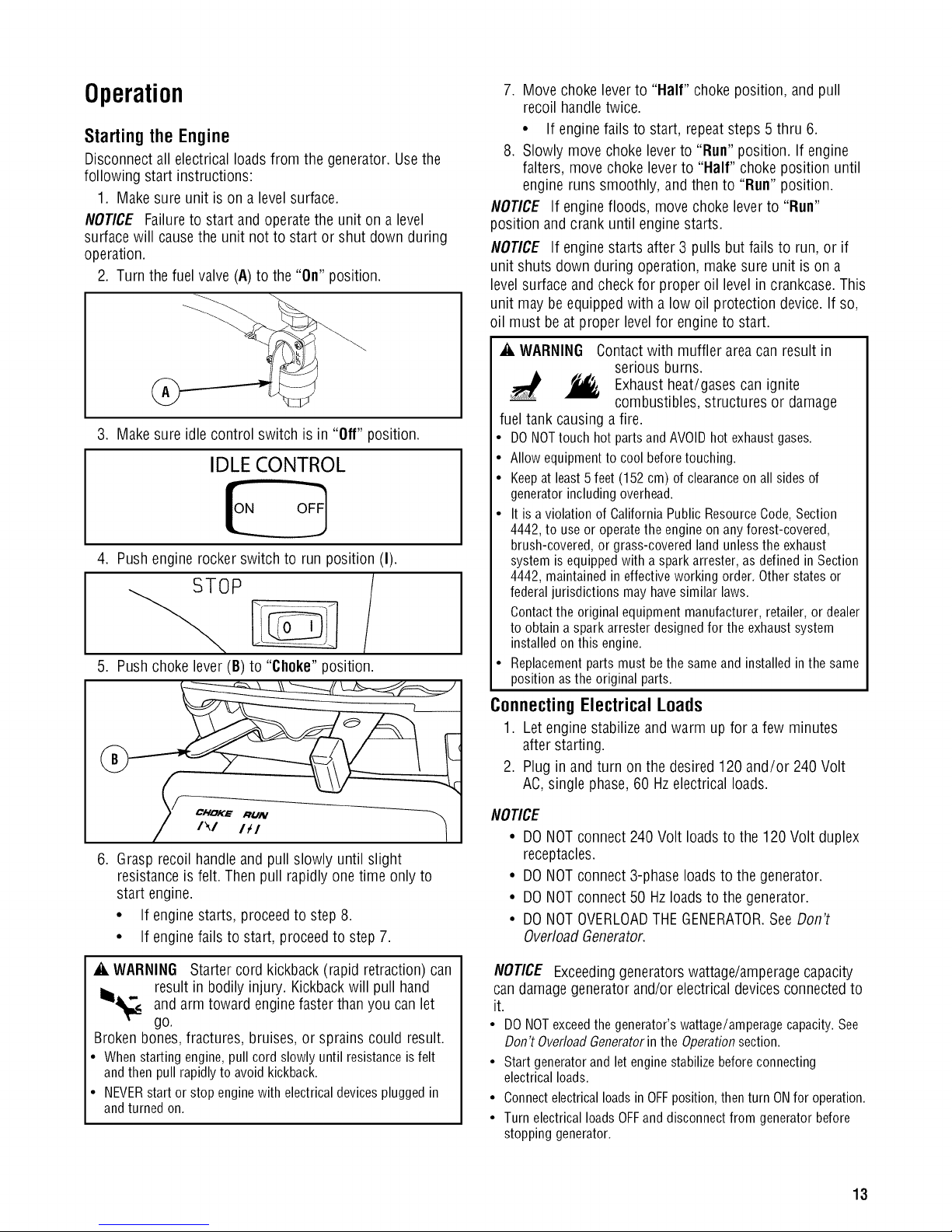
Operation
Starting the Engine
Disconnect all electrical loads from the generator. Usethe
following start instructions:
1. Make sure unit is on a level surface.
NOTICE Failureto start and operatethe unit on a level
surfacewill causethe unit not to start or shut down during
operation.
2. Turn thefuel valve (A) to the "On" position.
3. Make sure idle control switch is in "Off" position.
IDLE CONTROL
4. Push engine rocker switch to run position(I).
5. Push choke lever (B)to "Choke" position.
7. Move choke leverto "Half" choke position, and pull
recoil handletwice.
• If engine fails to start, repeatsteps 5 thru 6.
8. Slowly movechoke leverto "Run" position. If engine
falters, move choke lever to "Half" choke position until
engine runs smoothly, and then to "Run" position.
NOTICE If engine floods, move choke lever to "Run"
position and crank until enginestarts.
NOTICE If engine starts after 3 pulls but fails to run, or if
unit shuts down during operation, makesure unit is on a
level surfaceand check for proper oil level in crankcase.This
unit may be equipped with a low oil protection device. If so,
oil must beat proper levelfor engine to start.
_i, WARNING Contact with muffler area can result in
serious burns.
Exhaust heat/gases can ignite
combustibles, structures or damage
fuel tank causing a fire.
• DO NOTtouch hot parts andAVOIDhot exhaust gases.
• Allow equipmentto cool beforetouching.
• Keepat least5 feet (152 cm) of clearanceon all sides of
generator including overhead.
• It is aviolation of California Public Resource Code,Section
4442, to use or operate the engine on any forest-covered,
brush-covered, or grass-covered land unless the exhaust
system is equipped with aspark arrester, as defined in Section
4442, maintained in effective working order. Other states or
federaljurisdictions may have similar laws.
Contactthe original equipment manufacturer, retailer, or dealer
to obtain aspark arrester designed for the exhaust system
installed on this engine.
• Replacement parts must bethe same and installed inthe same
position asthe original parts.
._Z Ikl Itl
6. Grasp recoil handleand pull slowly until slight
resistance is felt. Then pull rapidly one time only to
start engine.
• If engine starts, proceedto step 8.
• If engine fails to start, proceedto step 7.
_i, WARNING Starter cord kickback (rapid retraction)can
result in bodily injury. Kickbackwill pull hand
llii_ - andarm toward enginefasterthan you can let
T-"
go.
Broken bones,fractures, bruises, or sprains could result.
• Whenstartingengine,pullcordslowlyuntilresistanceisfelt
andthenpullrapidlytoavoidkickback.
• NEVERstartor stopenginewith electricaldevicespluggedin
andturnedon.
Connecting Electrical Loads
1. Let engine stabilize and warm up for a few minutes
after starting.
2. Plug inand turn on the desired 120 and/or 240 Volt
!
AC,single phase,60 Hzelectrical loads.
NOtiCE
• DONOTconnect 240 Volt loads to the 120 Volt duplex
receptacles.
• DONOTconnect 3-phaseloads to the generator.
• DONOTconnect 50 Hzloadsto the generator.
• DONOTOVERLOADTHEGENERATOR.SeeDon't
OverloadGenerator.
NOTICE Exceeding generators wattage/amperage capacity
can damage generator and/or electrical devices connected to
it.
• DO NOTexceedthe generator's wattage/amperage capacity. See
Don't OverloadGeneratorin the Operationsection.
• Start generator and let engine stabilize beforeconnecting
electrical loads.
• Connectelectrical loads in OFFposition, thenturn ONfor operation.
• Turn electrical loads OFFand disconnect from generator before
stopping generator.
13
Stoppingthe Engine
1. Turn OFFand unplug all electrical loads from generator
panel receptacles.NEVERstart or stop enginewith
electrical devicesplugged in and turned ON.
2. Move idle control switch to "Off" position.
3. Let engine run at no-loadfor severalminutes to
stabilize internaltemperatures of engineand generator.
4. Push engine rocker switch to stop position (0).
_i, WARNING Backfire,fire or engine damagecould
occur.
_i, WARNING Storage batteriesgive off explosive
,- hydrogen gasduring recharging.
_'_ Hydrogen gas stays near battery for a
long time after battery has beencharged.
Slightest spark will ignite hydrogen and cause explosion.
You can be blinded or severelyinjured.
Batteryelectrolytefluid contains acid and is extremely
caustic.
Contactwith batteryfluid will causeseverechemical burns.
• DONOTallowanyopenflame,spark,heat,orlitcigarette
duringandfor severalminutesaftercharginga battery.
• Wearprotectivegoggles,rubberapron,andrubbergloves.
• DONOTstop engine bymoving chokecontrol to "Choke"
position (]",l ).
5. Move fuel valve to "Off" position.
Operating Automatic Idle Control
This feature is designedto greatly improve fuel economy.
When this switchis turned ON,the enginewill only run at
its normal high governedengine speed when electrical loads
are connected.When electrical loads are removed,the
engine will run at a reducedspeed.
With the switchoff, the enginewill run at the normal high
engine speed.Alwayshave the switchoff whenstartingand
stoppingthe engine.
Oil Pressure Shutdown
If engine oil pressuredrops below a preset level,an oil
switch will stop the engine. Checkoil levelwith dipstick.
If oil level isbetweenADDand FULLmark on dipstick:
1. DONOTtry to restart the engine.
2. Contact a Briggs & Stratton Authorized Dealer.
3. DONOToperate engine until oil pressureis corrected.
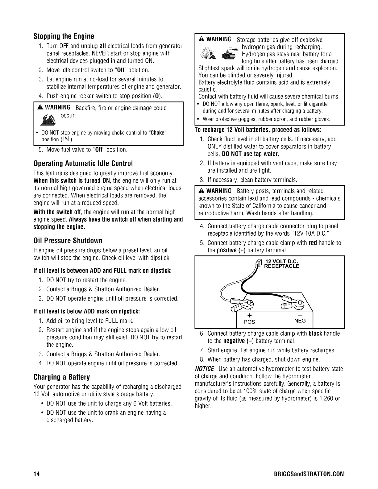
To recharge12 Volt batteries, proceed asfollows:
1. Checkfluid levelin all battery cells. If necessary,add
ONLYdistilled water to cover separators in battery
cells. DONOTusetapwater.
2. If batteryis equippedwith vent caps, make sure they
are installed and aretight.
3. If necessary,clean batteryterminals.
_i, WARNING Battery posts, terminals and related
accessoriescontain leadand leadcompounds - chemicals
known to the State of Californiato cause cancerand
reproductiveharm. Wash handsafter handling.
4. Connectbattery chargecable connector plug to panel
receptacleidentified by the words "12V IOA D.C."
5. Connectbattery chargecable clamp with red handleto
the positive(+) batteryterminal.
12 VOLT D.C.
RECEPTACLE
If oil level is
1.
Add oil to bring level to FULLmark.
2.
Restart engine and if the engine stops again a low oil
belowADDmark on dipstick:
pressure condition may still exist. DONOTtry to restart
the engine.
.
Contact a Briggs & Stratton Authorized Dealer.
4.
DONOToperateengine until oil pressure is corrected.
Charging a Battery
Your generator has the capability of recharging a discharged
12 Volt automotive or utility style storage battery.
• DONOTuse the unit to charge any 6 Volt batteries.
• DONOTuse the unit to crank an engine having a
discharged battery.
14 BRIGGSandSTRATTON.COIVl
+
POS NEG
6. Connectbattery chargecable clamp with blackhandle
to the negative(-) battery terminal.
7. Start engine. Let engine run while battery recharges.
8. When battery hascharged, shut down engine.
NOTICE Use an automotive hydrometerto test batterystate
of charge and condition. Follow the hydrometer
manufacturer's instructions carefully. Generally,a battery is
considered to be at 100% stateof charge when specific
gravity of its fluid (as measured by hydrometer) is 1.260 or
higher.
Cold WeatherOperation
Under certain weather conditions (temperatures below 40°F
[4°0] combined with high humidity), your generator may
experienceicing of the carburetor and/or the crankcase
breather system. To reduce this problem, you needto
perform the following:
1. Make sure generator hasclean,fresh fuel.
2. Openfuel valve(turn valve to open position).
3. Use SAE5W-30 oil.
4. Checkoil leveldaily or after every eight (8) hours of
operation.
5. Maintain generatorfollowing MaintenanceSchedulein
Maintenancesection.
6. Shelter unit from elements.
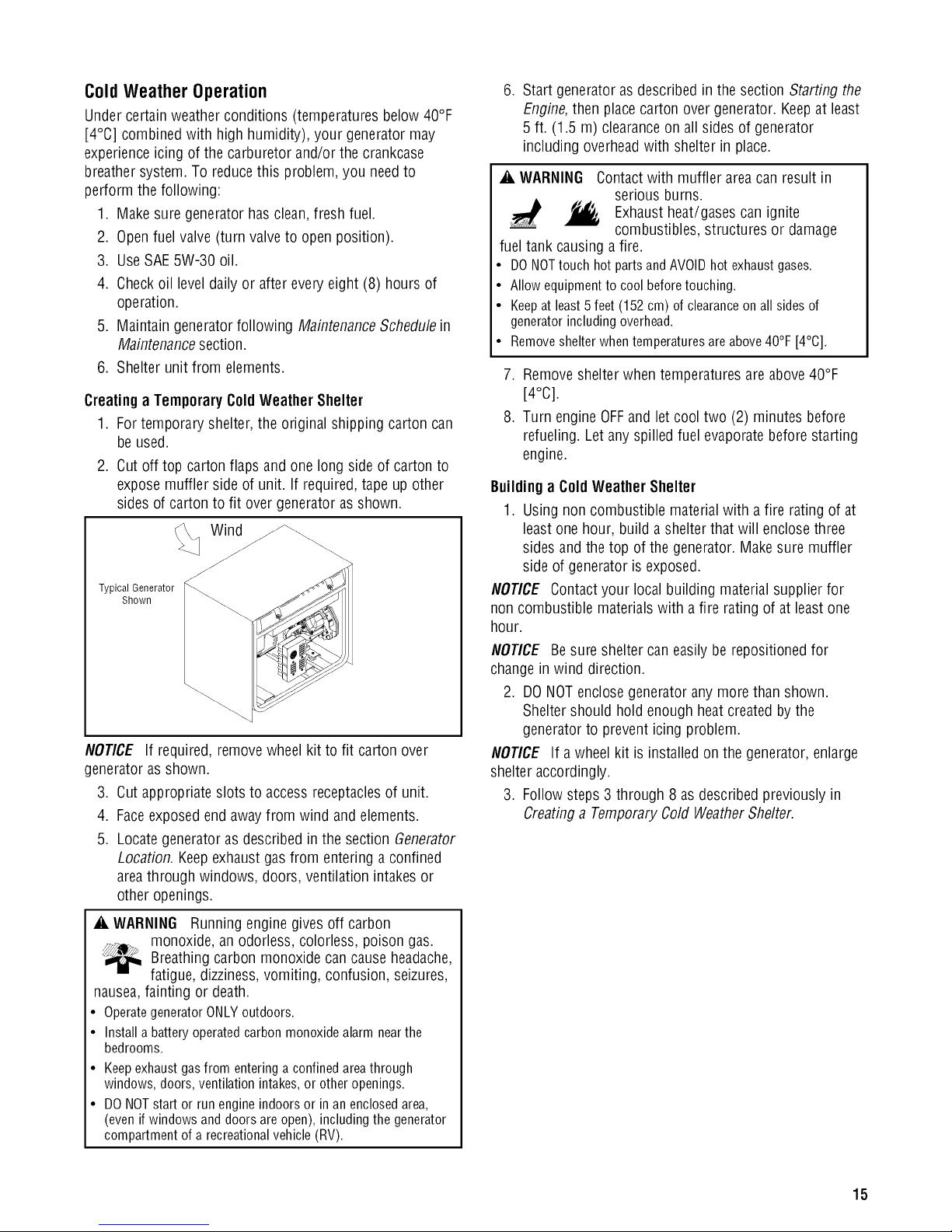
Creatinga TemporaryColdWeather Shelter
1. Fortemporary shelter,the original shipping carton can
be used.
2. Cut off top cartonflaps andone long sideof carton to
expose muffler side of unit. If required,tape up other
sides of carton to fit over generatoras shown.
Wind
Typical Generator
Shown
NOTICE If required, removewheel kit to fit carton over
generator asshown.
3. Cut appropriate slots to access receptaclesof unit.
4. Faceexposedend away from wind and elements.
5. Locate generatoras described in the section Generator
Location. Keepexhaust gasfrom entering aconfined
areathrough windows, doors, ventilation intakes or
other openings.
,
Start generator as described in the section Starting the
Engine,then placecarton over generator. Keepat least
5 ft. (1.5 m) clearanceon all sides of generator
including overheadwith shelter in place.
A WARNING Contactwith muffler area can result in
serious burns.
Exhaust
heat/gases can ignite
combustibles, structures or damage
fuel tank causinga fire.
• DONOTtouchhotpartsandAVOIDhot exhaustgases.
• Allowequipmentto coolbeforetouching.
• Keepatleast5 feet(152cm)of clearanceonall sidesof
generatorincludingoverhead.
• Removeshelterwhentemperaturesareabove40°F[4°C].
7. Removeshelter when temperatures are above 40°F
[4°C].
8. Turn engine OFFand let cool two (2) minutes before
refueling. Let anyspilled fuel evaporatebefore starting
engine.
Buildinga ColdWeather Shelter
1. Using noncombustible materialwith a fire rating of at
least one hour, build a shelter that will enclose three
sides and the top of the generator. Makesure muffler
side of generator is exposed.
NOTICE Contactyour local building materialsupplier for
non combustible materialswith a fire rating of at least one
hour.
NOTICE Besure shelter caneasily be repositioned for
changein wind direction.
2. DONOTenclose generator any more than shown.
Sheltershould hold enough heat createdby the
generatorto prevent icing problem.
NOTICE If a wheel kit is installed on the generator, enlarge
shelter accordingly.
3. Follow steps 3 through 8 asdescribed previously in
Creatinga TemporaryCold WeatherShelter.
A WARNING Runningengine gives off carbon
monoxide, an odorless, colorless, poison gas.
Breathingcarbon monoxidecancause headache,
fatigue, dizziness,vomiting, confusion, seizures,
nausea,fainting or death.
• OperategeneratorONLYoutdoors.
• Installa batteryoperatedcarbonmonoxidealarmnearthe
bedrooms.
Keepexhaustgas from entering a confined areathrough
windows, doors,ventilation intakes, or other openings.
DO NOTstart or run engine indoors or in an enclosedarea,
(even if windows anddoors are open), including the generator
compartment of arecreational vehicle (RV).
15
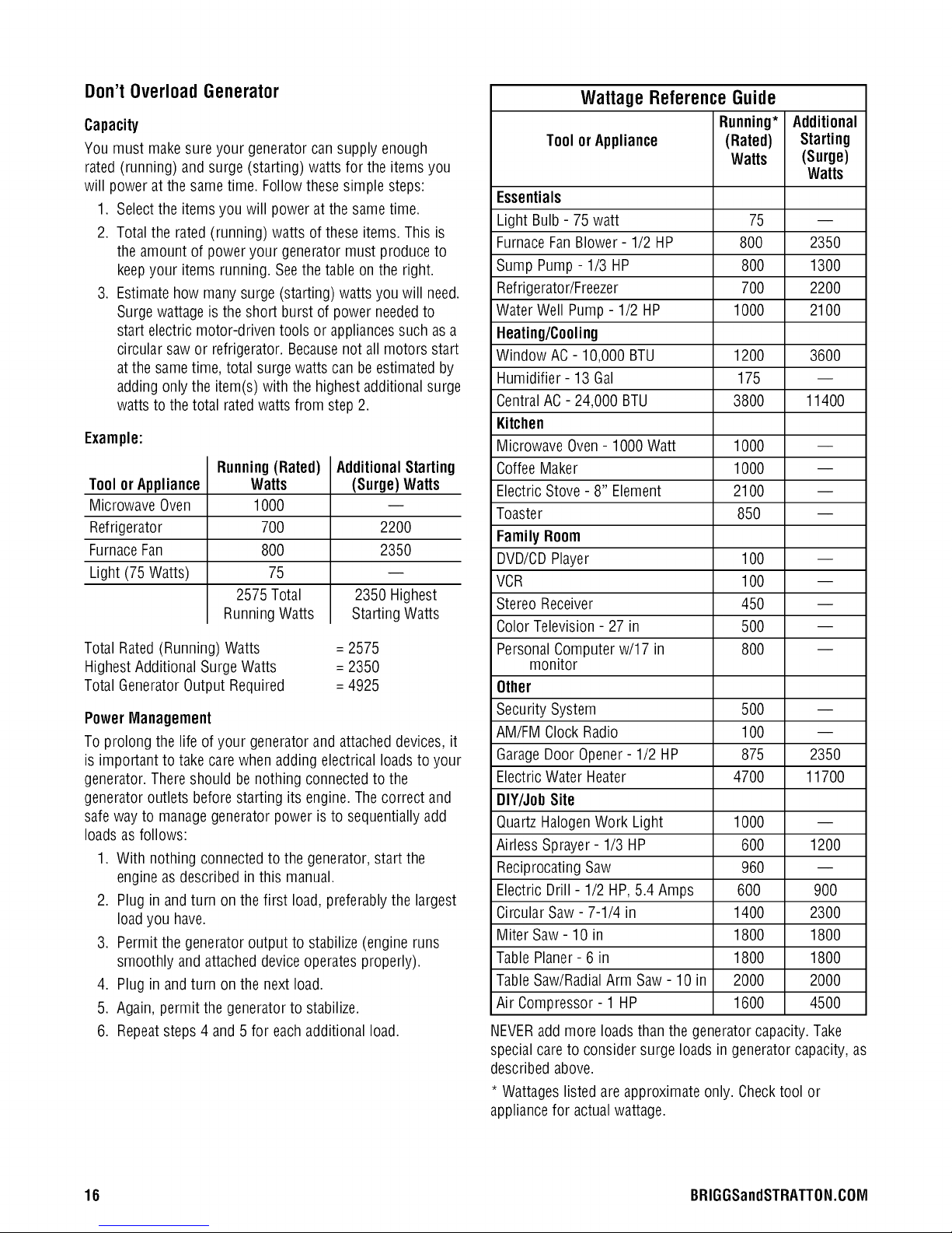
Don't Overload Generator
Capacity
You must make sureyour generator cansupply enough
rated (running) and surge (starting) watts for the items you
will power at the same time. Follow these simple steps:
1. Selectthe items you will power at the same time.
2. Total the rated(running) watts of these items. This is
the amount of power your generator must produce to
keepyour items running. Seethe table on the right.
3. Estimatehow many surge (starting) watts you will need.
Surge wattageis the short burst of power neededto
start electric motor-driven tools or appliancessuch as a
circular saw or refrigerator. Becausenot all motors start
atthe sametime, total surgewatts can be estimatedby
adding only the item(s) with the highest additionalsurge
watts to the total ratedwattsfrom step2.
Example:
Running(Rated)
Toolor Appliance
Microwave Oven
Refrigerator
FurnaceFan
Light (75 Watts)
Total Rated(Running) Watts = 2575
HighestAdditional SurgeWatts = 2350
Total GeneratorOutput Required =4925
Power Mlanagement
To prolong the life of your generatorand attacheddevices, it
is important to take care when adding electrical loadsto your
generator. Thereshould be nothing connectedto the
generator outlets before starting its engine.Thecorrect and
safe way to managegeneratorpower isto sequentially add
loads asfollows:
1. With nothing connectedto the generator,start the
engine asdescribed inthis manual.
2. Plug in andturn on the first load, preferablythe largest
load you have.
3. Permit the generatoroutput to stabilize (engineruns
smoothly and attacheddeviceoperates properly).
4. Plug in andturn on the next load.
5. Again, permit the generatorto stabilize.
6. Repeatsteps 4 and 5 for eachadditional load.
Watts
1000
7OO
8OO
75
2575 Total
RunningWatts
AdditionalStarting
(Surge) Watts
2200
2350
2350 Highest
Starting Watts
WattageReferenceGuide
Running* Additional
Tool orAppliance (Rated) Starting
Watts (Surge)
Watts
Essentials
Light Bulb - 75 watt 75 --
FurnaceFanBlower- 1/2 HP 800 2350
Sump Pump- 1/3 HP 800 1300
Refrigerator/Freezer 700 2200
Water Well Pump - 1/2 HP 1000 2100
Heating/Cooling
Window AC - 10,000 BTU 1200 3600
Humidifier- 13 Gal 175 --
CentralAC- 24,000 BTU 3800 11400
Kitchen
Microwave Oven- 1000 Watt 1000 --
CoffeeMaker 1000 --
Electric Stove - 8" Element 2100 --
Toaster 850 --
Family Room
DVD/CDPlayer 100 --
VCR 100 --
Stereo Receiver 450 --
Color Television- 27 in 500 --
PersonalComputer w/17 in 800 --
monitor
Other
Security System 500 --
AM/FM Clock Radio 100 --
GarageDoor Opener- 1/2 HP 875 2350
ElectricWater Heater 4700 11700
DIY/JohSite
Quartz HalogenWork Light 1000 --
Airless Sprayer- 1/3 HP 600 1200
Reciprocating Saw 960 --
Electric Drill - 1/2 HP, 5.4 Amps 600 900
Circular Saw - 7-1/4 in 1400 2300
Miter Saw- 10 in 1800 1800
TablePlaner- 6 in 1800 1800
TableSaw/RadialArm Saw - 10 in 2000 2000
Air Compressor - 1 HP 1600 4500
NEVERadd more loads than the generator capacity.Take
special careto consider surge loads in generator capacity, as
described above.
* Wattageslisted areapproximate only. Checktool or
appliancefor actualwattage.
16 BRIGGSandSTRATTON.COIVl
Maintenance
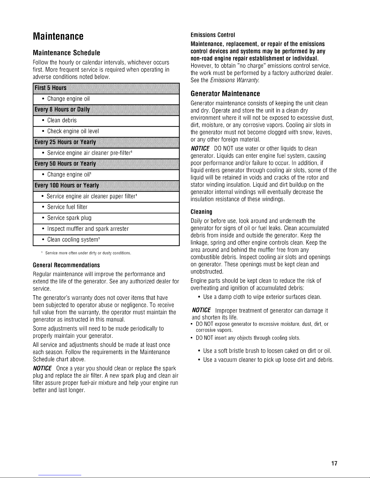
MaintenanceSchedule
Follow the hourly or calendarintervals, whichever occurs
first. More frequent serviceis required when operating in
adverseconditions noted below.
!
• Changeengine oil
• Cleandebris
• Checkengineoil level
• Service engineair cleanerpre-filter'
• Changeengine oil'
• Serviceengine air cleanerpaper filter'
• Servicefuel filter
• Servicespark plug
• Inspect muffler and spark arrester
• Cleancooling system'
1 Service more often under dirty or dusty conditions.
GeneralRecommendations
Regular maintenancewill improve the performance and
extend the life of the generator.Seeany authorizeddealer for
service.
Thegenerator's warranty does not cover items that have
been subjectedto operator abuseor negligence.To receive
full valuefrom the warranty, the operator must maintain the
generator asinstructed in this manual.
Someadjustments will needto be made periodically to
properly maintain your generator.
All service and adjustments should be made at least once
eachseason.Follow the requirementsin the Maintenance
Schedulechart above.
NOTICE Oncea year you should cleanor replacethe spark
plug and replacethe air filter. A new spark plug and clean air
filter assure proper fuel-air mixture and help your engine run
better and last longer.
EmissionsControl
Maintenance, replacement, or repair of the emissions
controldevicesand systemsmay be performedby any
non-roadengine repair establishmentor individual.
However,to obtain "no charge" emissions control service,
the work must beperformed by a factory authorizeddealer.
Seethe Emissions Warranty.
GeneratorMaintenance
Generatormaintenanceconsists of keepingthe unit clean
and dry. Operateand store the unit in a clean dry
environment where it will not be exposedto excessive dust,
dirt, moisture, or any corrosive vapors. Coolingair slots in
the generator must not become cloggedwith snow, leaves,
or any other foreign material.
NOTICE DO NOTusewater or other liquids to clean
generator. Liquids canenter engine fuel system, causing
poor performance and/or failure to occur. In addition, if
liquid enters generator through cooling air slots, some of the
liquid will be retainedin voids and cracks of the rotor and
stator winding insulation. Liquid anddirt buildup on the
generator internalwindings will eventually decreasethe
insulation resistanceof these windings.
Cleaning
Dailyor before use, look around and underneaththe
generatorfor signs of oil or fuel leaks. Cleanaccumulated
debris from inside and outside the generator. Keepthe
linkage, spring and other engine controls clean. Keepthe
areaaround andbehind the muffler free from any
combustible debris. Inspect cooling air slots and openings
on generator. Theseopenings must be kept clean and
unobstructed.
Engine parts should be kept cleanto reducethe riskof
overheating and ignition of accumulateddebris:
• Usea damp cloth to wipe exterior surfaces clean.
NOTICE Improper treatment of generator can damage it
and shorten its life.
• DO NOTexpose generator to excessivemoisture, dust, dirt, or
corrosive vapors.
• DONOTinsert any objects through cooling slots.
• Usea soft bristle brush to loosen cakedon dirt or oil.
• Usea vacuum cleanerto pick up loose dirt and debris.
17
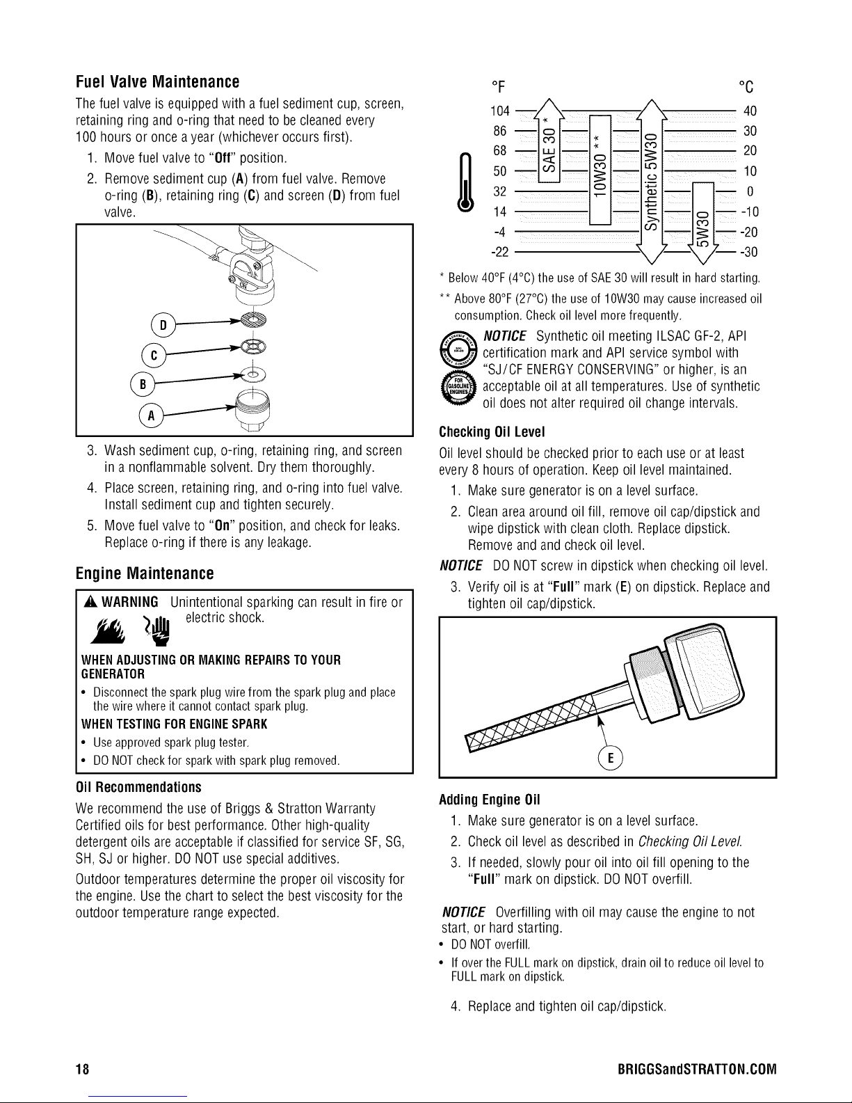
FuelValve Maintenance
Thefuel valve is equipped with a fuel sediment cup, screen,
retaining ring and o-ring that needto becleanedevery
100 hours or once a year (whichever occurs first).
1. Move fuel valve to "Off" position.
2. Removesediment cup (A) from fuel valve. Remove
o-ring (B), retaining ring (C) and screen (D) from fuel
valve.
oF oc
68 _mo >_20
104 n _, __ , !l_'X_ 40
86 _om__ _,_ o__ 30
so 10
32 o ._m -- 0
-2214-4 -- , l--___' -30-20-10
3. Wash sediment cup, o-ring, retaining ring, andscreen
in a nonflammable solvent. Drythem thoroughly.
4. Placescreen, retaining ring, and o-ring into fuel valve.
Install sedimentcup andtighten securely.
5. Move fuel valve to "On" position, and checkfor leaks.
Replaceo-ring if there is any leakage.
EngineMaintenance
_i, WARNING Unintentionalsparking can result in fire or
_ electric shock.
WHENADJUSTINGORMAKINGREPAIRSTOYOUR
GENERATOR
• Disconnectthesparkplugwirefromthesparkplugandplace
thewirewhereit cannotcontactsparkplug.
WHENTESTINGFORENGINESPARK
• Useapprovedsparkplugtester.
• DONOTcheckfor sparkwith sparkplugremoved.
* Below 40°F
** Above 80°F (27°C) the useof 10W30 may cause increasedoil
consumption. Oheckoil levelmore frequently.
CheckingOil Level
Oil level should be checked prior to each useor at least
every 8 hours of operation. Keepoil levelmaintained.
1. Make sure generator is on a level surface.
2. Cleanarea around oil fill, removeoil cap/dipstick and
NOTICE DO NOTscrew in dipstick when checking oil level.
3. Verify oil is at "Full" mark (E) on dipstick. Replaceand
(4°C)theuseofSAE30 will resultin hardstarting.
certification mark and API servicesymbol with
NOTICE Synthetic oil meeting ILSACGF-2,API
"SJ/CF ENERGYCONSERVING"or higher, is an
acceptableoil at all temperatures. Useof synthetic
oil does not alter required oil change intervals.
wipe dipstick with cleancloth. Replacedipstick.
Removeandand check oil level.
tighten oil cap/dipstick.
Oil Recommendations
We recommendthe useof Briggs & Stratton Warranty
Certified oils for best performance.Otherhigh-quality
detergent oils are acceptableif classified for serviceSF, SG,
SH, SJ or higher. DONOTuse specialadditives.
Outdoor temperatures determine the proper oil viscosity for
the engine. Usethe chart to select the best viscosity for the
outdoor temperature rangeexpected.
18 BRIGGSandSTRATTON.COIVl
AddingEngineOil
1. Make sure generator is on a level surface.
2. Checkoil level as described in CheckingOilLevel
3. If needed,slowly pour oil into oil fill opening to the
"Full" mark on dipstick. DONOToverfill.
NOTICE Overfilling with oil may causethe engine to not
start, or hard starting.
• DONOToverfill.
• Ifoverthe FULLmarkondipstick,drainoilto reduceoil levelto
FULLmarkondipstick.
4. Replaceand tighten oil cap/dipstick.
ChangingEngineOil
If you are usingyour generator under extremely dirty or
dusty conditions, or in extremelyhot weather, changethe oil
more often.
& CAUTION Avoid prolonged or repeated skin contact
with used motor oil.
• Used motor oil has beenshown to cause skin cancer in certain
laboratory animals.
• Thoroughly wash exposed areaswith soap and water.
POLLUTE.CONSERVERESOURCES.RETURN
USEDOILTOCOLLECTIONCENTERS.
KEEPOUTOFREACHOFCHILDREN.DON'T
Changethe oil while the engineis still warm from
running,as follows:
1. Make sure unit is on a level surface.
2. Disconnectthe spark plug wire from the spark plug and
placethe wire where it cannot contact spark plug.
3. Cleanarea around oil drain plug.The oil drain plug is
located at base of engine,opposite carburetor.
4. Removeoil drain plug and drain oil completely into a
suitable container.
5. Reinstall oil drain plug andtighten securely. Remove oil
cap/dipstick.
6. Slowly pour recommendedoil (about 30 oz.) into oil fill
opening. Pauseto permit oil to settle. Fill to "Full" mark
on dipstick.
7. Wipe dipstick cleaneachtime oil levelis checked. DO
NOToverfill.
8. Reinstall oil cap/dipstick. Tighten cap securely.
9. Wipe up any spilled oil.
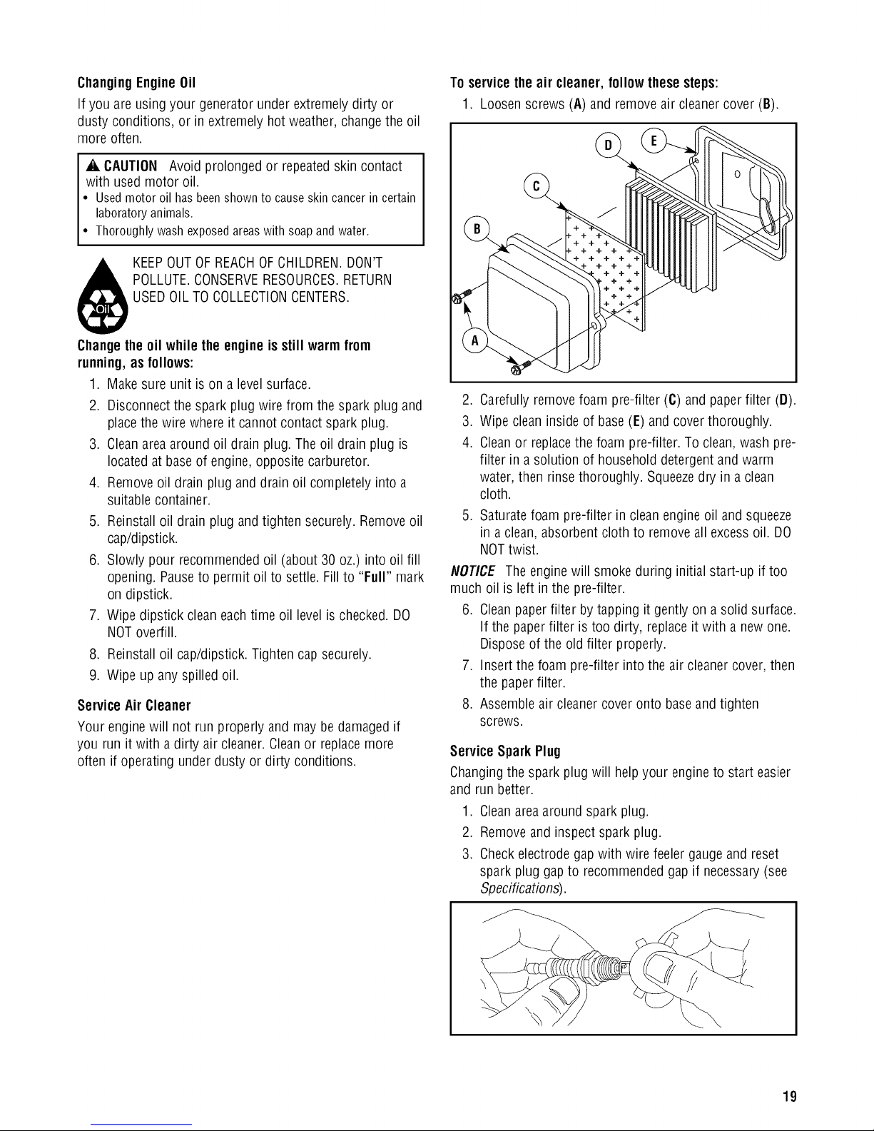
ServiceAir Cleaner
Your enginewill not run properly and may be damaged if
you run it with a dirty air cleaner.Cleanor replacemore
often if operating underdusty or dirty conditions.
To servicethe air cleaner, followthese steps:
1. Loosen screws (A) and removeair cleaner cover (B).
2. Carefully removefoam pre-filter (C) andpaper filter (D).
3. Wipe cleaninside of base(E) and cover thoroughly.
4. Cleanor replacethe foam pre-filter. To clean, wash pre-
filter in a solution of householddetergent and warm
water, then rinse thoroughly. Squeezedry in aclean
cloth.
5. Saturatefoam pre-filter in cleanengine oil and squeeze
in a clean, absorbent cloth to removeall excessoil. DO
NOTtwist.
NOTICE The engine will smoke during initial start-up if too
much oil is left inthe pre-filter.
6. Cleanpaperfilter by tapping it gently ona solid surface.
If the paperfilter is too dirty, replaceit with a new one.
Disposeof the old filter properly.
7. Insert the foam pre-filter into the air cleanercover, then
the paper filter.
8. Assembleair cleaner cover onto baseand tighten
screws.
Service Spark Plug
Changingthe spark plug will helpyour engineto start easier
and run better.
1. Cleanarea around spark plug.
2. Removeand inspect spark plug.
3. Checkelectrode gapwith wire feeler gauge and reset
spark plug gap to recommended gapif necessary(see
Specifications).
19
4. Replacespark plug if electrodesare pitted, burned or
porcelain is cracked. Usethe recommended
replacementspark plug. SeeSpecifications.
5. Install spark plug andtighten firmly.
InspectMluffler and Spark Arrester
Inspect the muffler for cracks, corrosion, or other damage.
Removethe spark arrester, if equipped, and inspectfor
damageor carbon blockage. If replacementparts are
required, make sure to use only original equipment
replacementparts.
_i, WARNING Contact with muffler area can result in
serious burns.
Exhaust heat/gases can ignite
combustibles, structures or damage
fuel tank causing a fire.
• DO NOTtouch hot parts andAVOID hot exhaust gases.
• Allow equipment to cool before touching.
• Keepat least5 feet (152 cm) of clearanceon all sidesof
generator including overhead.
• It is aviolation of California Public Resource Code,Section
4442, to use or operate the engineon any forest-covered,
brush-covered, or grass-covered land unlessthe exhaust
system is equipped with aspark arrester, as defined in Section
4442, maintained in effective working order. Otherstates or
federal jurisdictions may have similar laws.
Contactthe original equipment manufacturer, retailer, or dealer
to obtain a sparkarrester designed for the exhaust system
installed on this engine.
• Replacement parts must bethe same and installed inthe same
position asthe original parts.
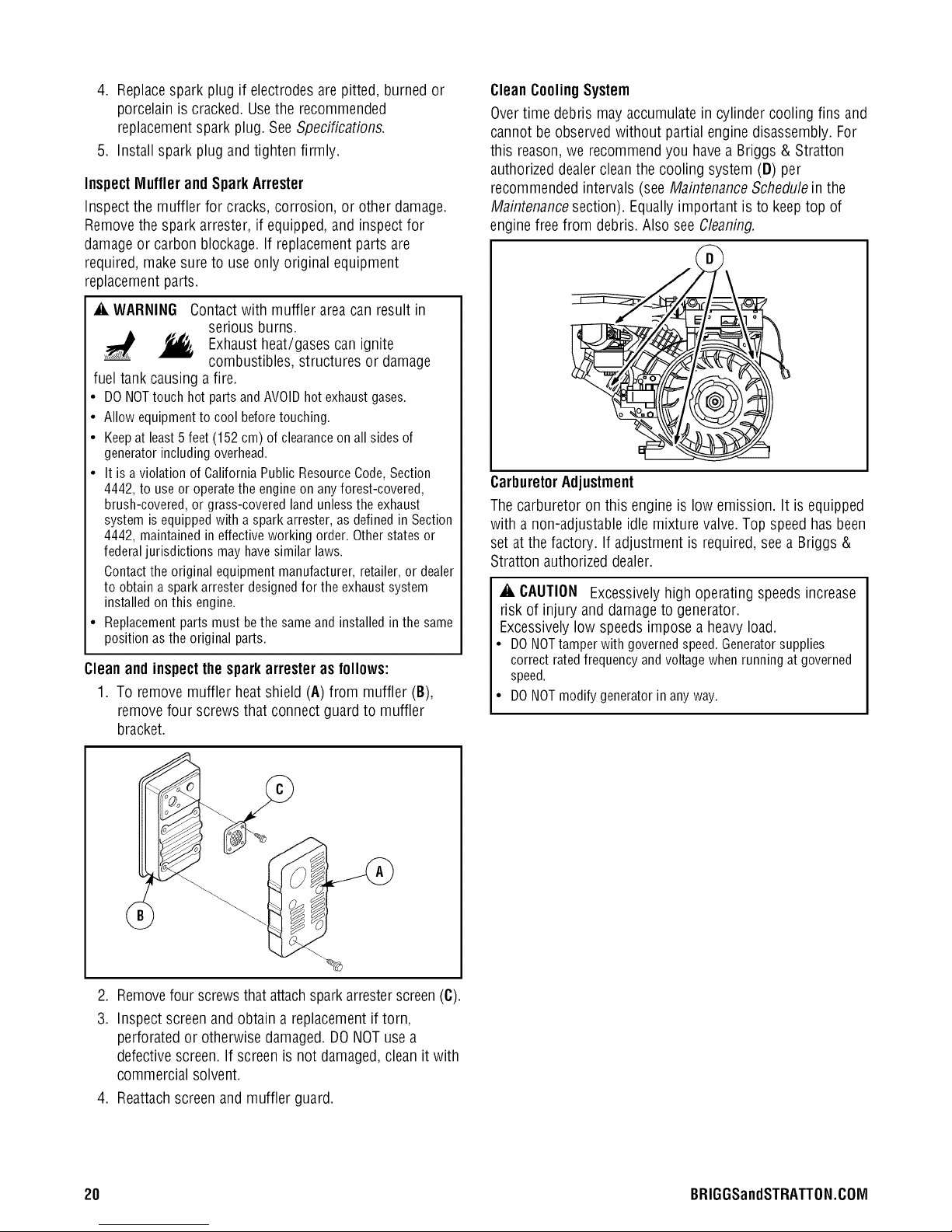
Cleanand inspectthesparkarresteras follows:
1. To remove muffler heatshield (A) from muffler (B),
removefour screws that connect guard to muffler
bracket.
CleanCoolingSystem
Overtime debris may accumulatein cylinder cooling fins and
cannot be observedwithout partial enginedisassembly. For
this reason,we recommendyou havea Briggs & Stratton
authorized dealerclean the cooling system (D) per
recommended intervals (seeMaintenanceScheduleinthe
Maintenancesection). Equally important is to keeptop of
engine freefrom debris. Also see Cleaning.
'\
CarburetorAdjustment
Thecarburetor on this engine is low emission. It is equipped
with a non-adjustable idle mixture valve. Top speed has been
set at the factory. If adjustment is required,see a Briggs &
Stratton authorized dealer.
_i, CAUTION Excessively high operating speeds increase
risk of injury and damage to generator.
Excessively low speeds impose a heavy load.
• DO NOTtamper with governedspeed. Generatorsupplies
correct rated frequency and voltage when running at governed
speed.
• DO NOTmodify generator in any way.
.
Removefour screwsthat attachsparkarresterscreen(C).
3.
Inspect screenand obtain areplacementif torn,
perforated or otherwise damaged. DONOTuse a
defective screen.If screenis not damaged,clean it with
commercial solvent.
4. Reattachscreen and muffler guard.
20 BRIGGSandSTRATTON.COIVl
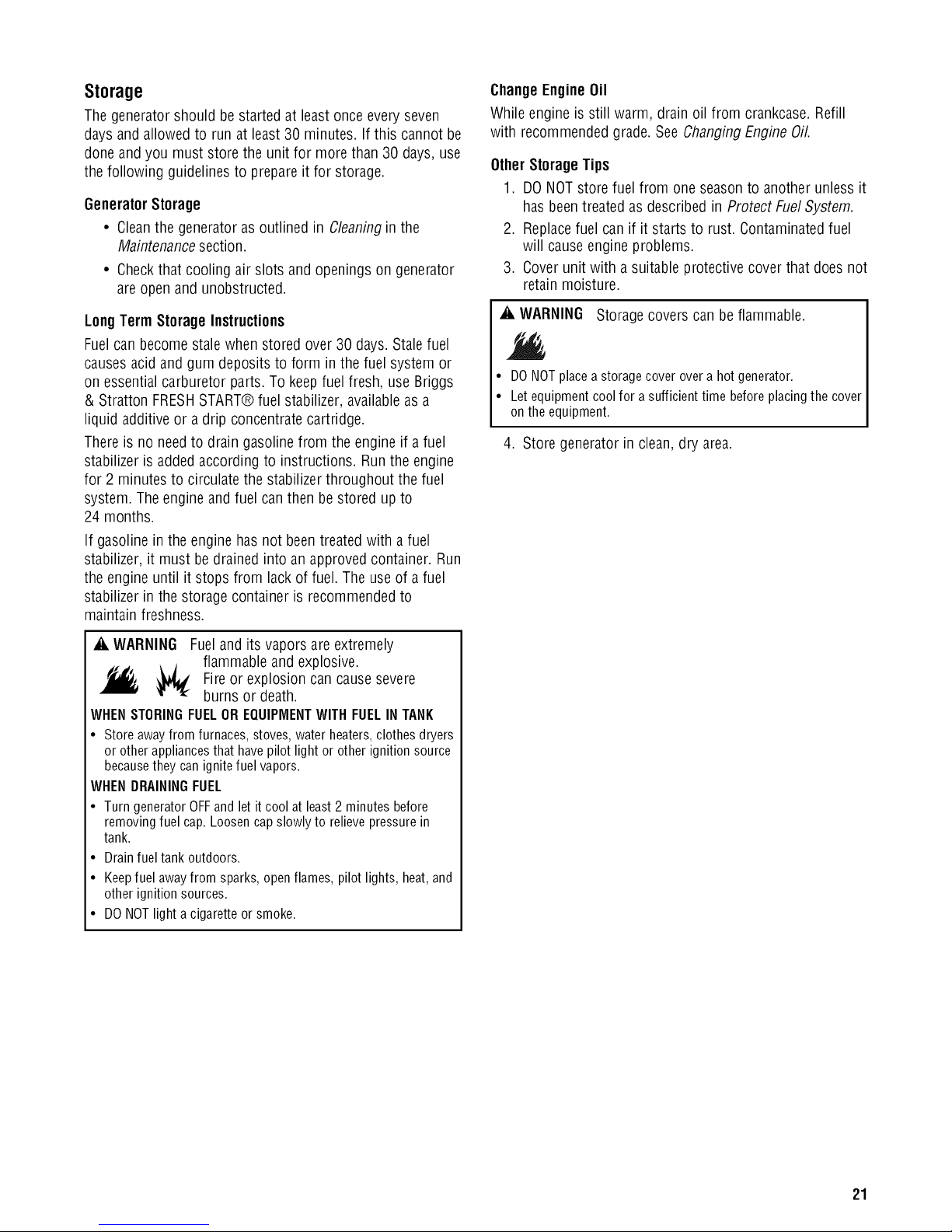
Storage
Thegenerator should be started at leastonce every seven
days and allowed to run at least 30 minutes. If this cannot be
done and you must store the unit for more than 30 days,use
the following guidelines to prepare it for storage.
GeneratorStorage
• Cleanthe generator as outlined in Cleaningin the
Maintenancesection.
• Checkthat cooling air slots and openingson generator
are open and unobstructed.
LongTerm StorageInstructions
Fuelcan becomestale when stored over 30 days.Stalefuel
causesacid and gum deposits to form in the fuel system or
on essential carburetor parts. To keepfuel fresh, use Briggs
& Stratton FRESHSTART® fuel stabilizer, availableasa
liquid additive or adrip concentratecartridge.
Thereis no needto drain gasolinefrom the engineif a fuel
stabilizer is added according to instructions. Runthe engine
for 2 minutes to circulate the stabilizerthroughout the fuel
system. The engine andfuel canthen be stored up to
24 months.
If gasoline in the engine hasnot beentreated with a fuel
stabilizer, it must bedrained into an approvedcontainer. Run
the engine until it stops from lack of fuel. The useof a fuel
stabilizer in the storage container is recommended to
maintain freshness.
ChangeEngineOil
While engine is still warm, drain oil from crankcase.Refill
with recommended grade.See Changing Engine Oil.
OtherStorageTips
1. DONOTstore fuel from one seasonto another unless it
has beentreated as described in Protect FuelSystem.
2. Replacefuel can if it starts to rust. Contaminatedfuel
will cause engine problems.
3. Cover unit with a suitable protective coverthat does not
retain moisture.
_i, WARNING Storagecovers can be flammable.
• DO NOTplace a storage cover overa hot generator.
• Let equipment coolfor a sufficient time before placing the cover
on the equipment.
4. Store generator in clean, dry area.
_i, WARNING Fueland its vapors are extremely
flammable and explosive.
_ J
_, _ Fire or explosion can causesevere
burns or death.
WHENSTORINGFUELOREQUIPMENTWITHFUELINTANK
• Store away from furnaces, stoves, water heaters,clothesdryers
or other appliances that have pilot light or other ignition source
becausethey can ignite fuel vapors.
WHENDRAININGFUEL
• Turn generator OFFand let itcool at least2 minutes before
removing fuel cap. Loosen cap slowly to relievepressure in
tank.
• Drain fuel tank outdoors.
• Keepfuel awayfrom sparks, open flames, pilot lights, heat, and
other ignition sources.
• DO NOTlight a cigarette or smoke.
21
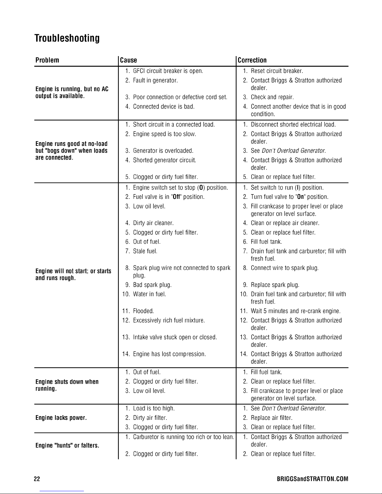
Troubleshooting
Problem
Engineisrunning,but noAC
outputis available.
Enginerunsgoodat no-load
but "bogs down"when loads
are connected.
Enginewill notstart; or starts
and runsrough.
Engineshutsdownwhen
running.
Enginelackspower.
Engine"hunts" or falters.
Cause
1. GFCIcircuit breakeris open.
2. Fault in generator.
3. Poor connection or defectivecord set.
4. Connecteddeviceis bad.
1. Short circuit in aconnectedload.
,
Enginespeed is too slow.
3.
Generatoris overloaded.
4.
Shorted generator circuit.
5.
Cloggedor dirty fuel filter.
1.
Engineswitch setto stop (0) position. 1.
2.
Fuelvalveis in "Off"position. 2.
3. Low oil level.
4. Dirty air cleaner.
5. Cloggedor dirty fuel filter.
6. Out of fuel.
7. Stalefuel.
,
Spark plug wire not connectedto spark
plug.
9. Badspark plug.
10. Water in fuel.
11. Flooded.
12. Excessivelyrich fuel mixture.
13. Intakevalvestuck open or closed.
14. Engine has lost compression.
1. Out of fuel.
2. Cloggedor dirty fuel filter.
3. Low oil level.
1. Loadis too high.
2. Dirty air filter.
3. Cloggedor dirty fuel filter.
1. Carburetoris runningtoo rich or too lean.
2. Cloggedor dirty fuel filter.
Correction
1. Resetcircuit breaker.
2. Contact Briggs & Stratton authorized
dealer.
3. Checkand repair.
4. Connectanotherdevice that is in good
condition.
1. Disconnectshorted electrical load.
.
Contact Briggs & Stratton authorized
dealer.
3.
SeeDon't OverloadGenerator.
4.
Contact Briggs & Stratton authorized
dealer.
5.
Cleanor replacefuel filter.
Setswitch to run (I) position.
Turnfuel valveto "On"position.
3. Fillcrankcaseto proper levelor place
generatoron level surface.
4. Cleanor replaceair cleaner.
5. Cleanor replacefuel filter.
6. Fillfuel tank.
7. Drainfuel tank and carburetor; fill with
fresh fuel.
8. Connectwire to spark plug.
9. Replacespark plug.
10. Drainfuel tank and carburetor; fill with
fresh fuel.
11. Wait 5 minutes and re-crank engine.
12. Contact Briggs & Stratton authorized
dealer.
13. Contact Briggs & Stratton authorized
dealer.
14. Contact Briggs & Stratton authorized
dealer.
1. Fillfuel tank.
2. Cleanor replacefuel filter.
3. Fillcrankcaseto proper levelor place
generatoron level surface.
1. SeeDon't OverloadGenerator.
2. Replaceair filter.
3. Cleanor replacefuel filter.
1. Contact Briggs & Stratton authorized
dealer.
2. Cleanor replacefuel filter.
22 BRIGGSandSTRATTON.COIVl
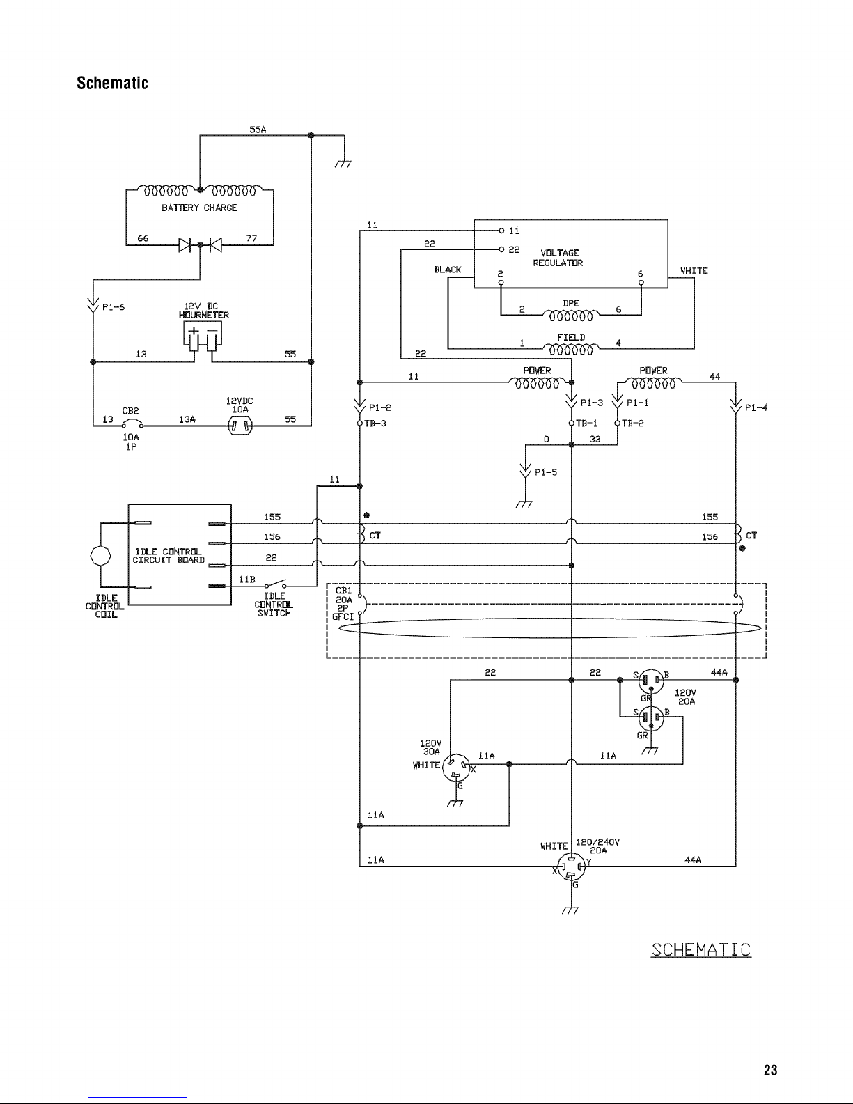
Schematic
55A
BATTERY CHARGE
PI-6 12V DC
CB2
13 _ 13A
loA
1P
IDLE CONTROL
CIRCUIT BOARD ==
IDLE
CONTROL
COIL
HQURMETER
12VDC
155
156
22
LiB oi_o_____
IDLE
CONTROL
SWITCH
11
22 J 022 VOLTAGE J
i oli i
BLA_ _ REGULATOR (_ I WH__.ITE
|
55
1
/'PI-2
_TB-3
II
I 20A
I 2P
GFCI '
m
m
i
L ....
22
11
POWER
\
\
0
PI-5
22
POWER
155
156
44
/
t PI-4
CT
.... l
I
i
I
I
i
m
i
IIA
IIA
120V
30A
WHITE_
WHITE
12o/a4ov
2oA
SCHEHATIC
23
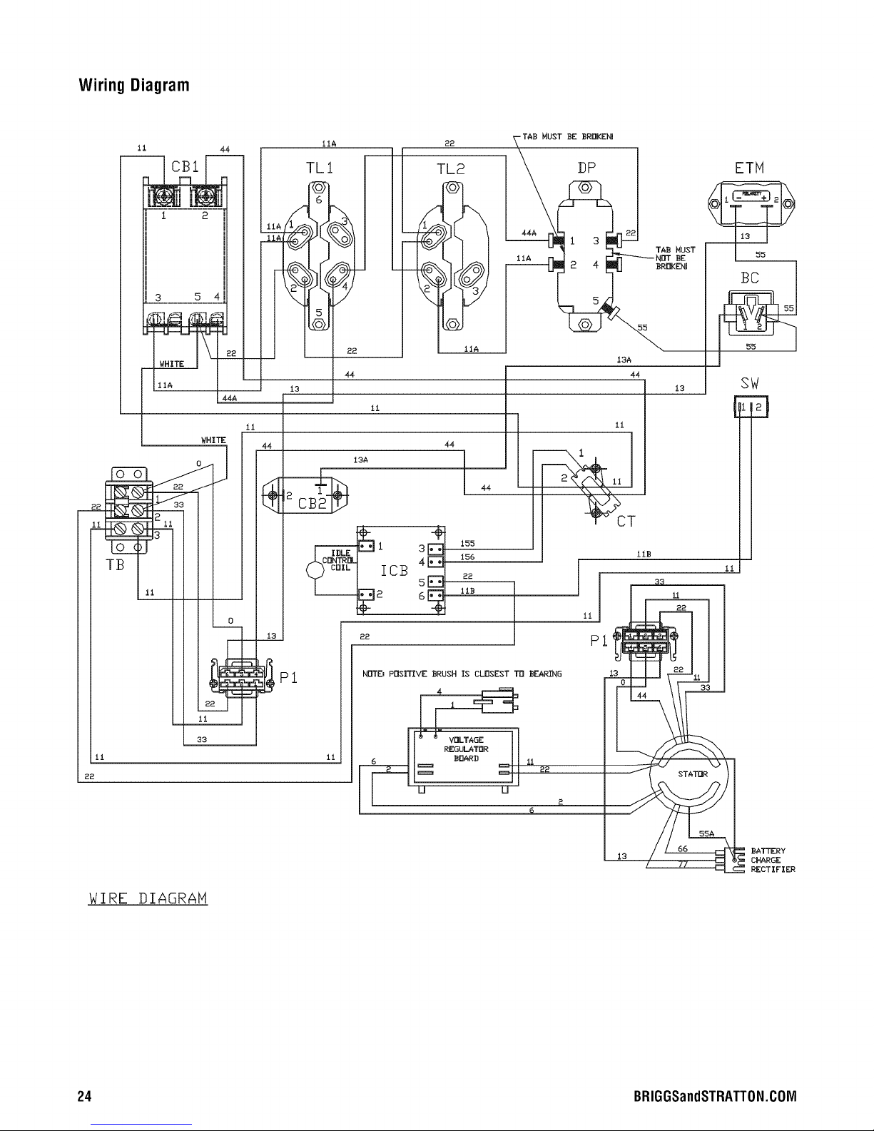
WiringDiagram
11
r..............
0
WHITE
44
IIA
TL1
22
TL2
MUST ]BE BRDKENI
DP
ETM
--i
L 55
11A
44
13
ii
ii
44
13
li
22
WIRE DIAGRAM
ii
o__
N
=r
LI
33
BATTERY
77
CHARGE
RECTIFIER
24 BRIGGSandSTRATTON.COIVl
Warranties
California,U.S. EPA,andBriggs& Stratton
CorporationEmissionsControlWarranty
Statement
YourWarranty RightsAndObligations
The CaliforniaAir ResourcesBoard,U.S. EPA,and Briggs &
Stratton (B&S) are pleasedto explainthe emissions control
system warranty on your ModelYear2008 andlater
engine/equipment. In California,new small off-road engines
must be designed, built, and equipped to meetthe State's
stringent anti-smog standards. B&Smust warrant the
emissions control system on your engine/equipmentfor the
periods of time listed below provided there has been no
abuse, neglect,or improper maintenanceof your small off-
road engine.
Your emissions control system may include partssuch as
the carburetor or fuel injection system, fuel tank, ignition
system, and catalytic converter. Also included may behoses,
belts, connectors, sensors, andother emissions-related
assemblies.Wherea warrantable condition exists, B&S will
repair your engine/equipmentat no cost to you including
diagnosis, parts, and labor.
Manufacturer'sWarrantyCoverage:
Small off-road engines arewarranted for two years. If any
emissions-related part on your engine/equipment is
defective,the part will be repaired or replacedby B&S.
Owner's WarrantyResponsibilities:
• As the small engine/equipment owner, you are
responsiblefor the performance of the required
maintenancelisted in your owner's manual. B&S
recommendsthat you retainall receipts covering
maintenanceonyour engine/equipment, but B&S
cannot deny warranty solely for the lack of receiptsor
your failure to ensurethe performanceof all scheduled
maintenance.
• As the engine/equipmentowner,you should however
be awarethat B&Smay deny you warranty coverageif
your engine/equipmentor a part hasfailed due to
abuse, neglect,improper maintenance,or unapproved
modifications.
• Youare responsiblefor presentingyour
engine/equipmentto a B&Sdistribution center,
servicing dealer,or other equivalententity, as
applicable, assoon as a problem exists. Thewarranty
repairsshould be completed in a reasonableamount of
time, not to exceed30 days. If you haveany questions
regardingyour warranty rights andresponsibilities, you
should contact B&Sat (414) 259-5262.
Briggs& Stratton EmissionsControlWarrantyProvisions
Thefollowing are specific provisions relativeto your
Emissions Control Warranty Coverage.It is in addition to the
B&S enginewarranty for non-regulatedengines found in the
Operator's Manual.
1. Warranted Emissions Parts
Coverageunder this warranty extends only to the parts
listed below (the emissions control systems parts) to
the extentthese parts were present on the engine
purchased.
a. FuelMetering System
• Cold start enrichment system (soft choke)
• Carburetorand internal parts
• Fuelpump
• Fuelline, fuel line fittings, clamps
• Fueltank, capand tether
• Carboncanister
b. Air Induction System
• Air cleaner
• Intake manifold
• Purgeand vent line
C,
Ignition System
• Spark plug(s)
• Magnetoignition system
d,
CatalystSystem
• Catalyticconverter
• Exhaustmanifold
• Air injection system or pulse valve
e. Miscellaneous Items Used in Above Systems
• Vacuum,temperature, position, time sensitive
valvesandswitches
• Connectorsand assemblies
,
Length of Coverage
For a period of two yearsfrom date of original
purchase, B&S warrants to the original purchaser and
eachsubsequent purchaserthat the engine is designed,
built, and equippedso as to conform with all applicable
regulations adopted by the Air Resources Board; that it
is free from defectsin materialand workmanship that
could cause the failure of a warranted part; and that it
is identical in all material respects to the engine
described in the manufacturer's application for
certification. The warranty period beginson the datethe
engine is originally purchased.
25
Thewarranty on emissions-related parts is asfollows:
• Anywarranted part that is not scheduledfor
replacementas required maintenancein the owner's
manual supplied, is warranted for the warranty period
stated above. If any such part fails during the period of
warranty coverage,the part will be repairedor replaced
by B&S at no chargeto the owner. Any such part
repairedor replacedunder the warranty will be
warranted for the remaining warranty period.
• Anywarranted part that is scheduled only for regular
inspection in the owner's manual supplied, is warranted
for the warranty period statedabove. Any such part
repairedor replacedunder warranty will be warranted
for the remaining warranty period.
• Anywarranted partthat is scheduledfor replacementas
requiredmaintenancein theowner's manualsupplied, is
warrantedfor the period of time prior to the first
scheduledreplacementpointfor that part. If the part fails
prior to thefirst scheduled replacement,the part will be
repairedor replacedby B&S at no charge to the owner.
Anysuch part repairedor replacedunderwarrantywill
be warrantedfor the remainder of the period prior to the
first scheduledreplacementpointfor the part.
• Addon or modified parts that are not exempted by the
Air Resources Board may not be used.The useof any
non exempted add on or modified parts by the owner
will be grounds for disallowing a warranty claim. The
manufacturer will not be liable to warrantfailures of
warranted parts causedbythe useof a non exempted
add on or modified part.
3. ConsequentialCoverage
Coverageshall extend to the failure of anyengine
components causedby the failure of anywarranted
emissions parts.
4. Claimsand CoverageExclusions
Warranty claims shall be filed according to the
provisions of the B&S enginewarranty policy. Warranty
coveragedoes not apply to failures of emissions parts
that are not original equipment B&S partsor to parts
that fail due to abuse, neglect, or improper maintenance
as set forth in the B&S engine warranty policy. B&Sis
not liable for warranty coverageof failures of emissions
parts causedby the useof add-on or modified parts.
LookFor RelevantEmissionsDurability Period andAir
IndexInformationOnYour EngineEmissionsLabel
Enginesthatare certified to meetthe CaliforniaAir
ResourcesBoard (CARD)Emissions Standardmust display
information regardingthe Emissions Durability Period and
the Air Index. Briggs & Stratton makesthis information
availableto the consumer on our emissions labels. The
engine emissions labelwill indicate certification information.
TheEmissionsDurabilityPerioddescribesthe number of
hours of actual runningtime for which the engine is certified
to be emissions compliant, assuming proper maintenancein
accordancewith the Operating& Maintenance Instructions.
Thefollowing categoriesare used:
Moderate:
Engine is certified to be emissions compliant for 125 hours
of actual enginerunning time.
Intermediate:
Engine is certified to be emissions compliant for 250 hours
of actual enginerunning time.
Extended:
Engine is certified to be emissions compliant for 500 hours
of actual enginerunning time.
Forexample,a typical walk-behind lawn mower is used 20 to
25 hours peryear. Therefore,the Emissions Durability
Period of anengine with an intermediate rating would
equateto 10to 12 years. Briggs & Stratton enginesare
certified to meet the United States EnvironmentalProtection
Agency (USEPA)Phase2 emissions standards.For Phase2
certified engines, the Emissions CompliancePeriod referred
to on the EmissionsCompliancelabel indicatesthe number
of operating hours for which the engine has beenshown to
meet Federalemissions requirements.
Forengines less than 225 cc displacement.
CategoryC= 125 hours
CategoryB= 250 hours
CategoryA= 500 hours
Forengines of 225 cc or more displacement.
CategoryC= 250 hours
CategoryB= 500 hours
CategoryA= 1000 hours
26 BRIGGSandSTRATTON.COM

Effective December 1,2005 replaces all undatedWarranties and all Warranties dated before December 1, 2005
LIMITED WARRANTY
Briggs& StrattonPowerProductsGroup,LLCwill repairor replace,freeof charge,anypart(s)of theportablegeneratorthat isdefectivein materialor
workmanshipor both.Transportationchargesonproductsubmittedfor repairor replacementunderthiswarrantymustbebornebypurchaser.This
warrantyiseffectivefor thetime periodsandsubjecttotheconditionsstatedbelow.Forwarrantyservice,findthenearestAuthorizedServiceDealerin
ourdealerIocatormapatBRIGGSandSTRATTON.COM.
THEREIS NO OTHEREXPRESSWARRANTY. IMPLIEDWARRANTIES, INCLUDINGTHOSEOFMERCHANTABILITYAND FITNESSFOR A PARTICULAR
PURPOSE,ARELIMITEDTO ONEYEARFROM PURCHASE,ORTO THEEXTENTPERMITTEDBY LAW. ANY ANDALL IMPLIED WARRANTIESARE
EXCLUDED.LIABILITY FOR INCIDENTALOR CONSEQUENTIALDAMAGESARE EXCLUDEDTO THEEXTENTEXCLUSIONIS PERMITTEDBY LAW. Some
states or countries do not allow limitations on how long an implied warranty lasts, and some states or countries do not allow the exclusion or limitation
of incidental or consequential damages, so the above limitation and exclusion maynot apply to you. This warranty gives you specific legal rights and
you may also have other rights which vary from state to state or country to country.
Engine All othercomponents
*Secondyearpartsonly
Thewarranty period begins on the date of purchase by the first retail end user, and continues for the period of time stated above. "Consumer Use" means
personal residential household use by a retail consumer. "Commercial Use"means all other uses,including use for commercial, income producing or rental
purposes. Onceequipment has experienced commercial use, it shall thereafter be considered as commercial use for purposes of this warranty. Equipment
used for prime power in place of utility are not applicable to this warranty.
NO WARRANTYREGISTRATIONIS NECESSARYTOOBTAINWARRANTYON BRIGGS& STRATTONPRODUCTS.SAVEYOURPROOFOFPURCHASE
RECEIPT.IF YOU DO NOTPROVIDEPROOFOFTHE INITIAL PURCHASEDATEAT THE TIMEWARRANTY SERVICEIS REQUESTED,THE MANUFACTURING
DATEOFTHE PRODUCTWILL BE USEDTO DETERMINETHEWARRANTY PERIOD.
We welcome warranty repair and apologize to you for being inconvenienced. Any Authorized Service Dealermay perform warranty repairs. Most warranty
repairs are handled routinely, but sometimes requests for warranty service may not be appropriate. For example, warranty service would not apply if
equipment damage occurred becauseof misuse, lack of routine maintenance, shipping, handling, warehousing or improper installation. Similarly, the
warranty is void if the manufacturing dateor the serial number on the portable generator has been removed or the equipment has been altered or modified.
During the warranty period, the Authorized Service Dealer, at its option, will repair or replaceany part that, upon examination, isfound to bedefective under
normal use and service. This warranty will not cover the following repairs andequipment:
Normal Wear: Outdoor Power Equipment, like all mechanical devices, needs periodic parts and service to perform well. This warranty does not cover
repair when normal use has exhausted the life of a part orthe equipment.
InstallationandMaintenance:Thiswarrantydoesnotapplyto equipmentor partsthathavebeensubjectedto improperorunauthorizedinstallationor
alterationandmodification,misuse,negligence,accident,overloading,overspeeding,impropermaintenance,repairorstoragesoas,in ourjudgment,
to adverselyaffectitsperformanceandreliability.Thiswarrantyalsodoesnotcovernormalmaintenancesuchasadjustments,fuelsystemcleaning
andobstruction(dueto chemical,dirt, carbon,lime,etc.).
Other Exclusions:This warranty excludes wear items such as o-rings, filters, etc., or malfunctions resulting from accidents, abuse, modifications,
alterations, or improper servicing orfreezing or chemical deterioration. Accessory parts such as generator adapter cord sets and storage covers are
excluded from the product warranty. This warranty excludesfailures due to acts of God and other force majeure events beyond the manufacturers
control. Also excluded is used, reconditioned, and demonstration equipment; equipment used for prime power in placeof utility power andequipment
used in life support applications. 198184E,Rev.C,12/31/2006
BRIGGS& STRATTONPOWERPRODUCTSGROUP,LLC
JEFFERSON,Wl, USA
27

®
PortableGenerator
ProductSpecifications
Starting Wattage ........................ 5,000 Watts
Wattage* . ............................. 4,000 Watts
ACVoltage ........................... 120/240 Volts
at 240 Volts ........................... 16.6 Amps
at 120 Volts ........................... 33.3 Amps
Frequency ........................ 60 Hzat 3600 rpm
Phase ................................ Single Phase
Displacement ................... 13.12 cu. in. (215 cc)
Spark Plug Gap ................... 0.030 in. (0.76 mm)
FuelCapacity ............... 4.5 U.S. Gallons(17 Liters)
Oil Capacity ................... 30 Ounces(0.89 Liters)
CommonServiceParts
Air Cleaner.......................... 491588 or 5043
Pre-Cleaner................................ 491435
Resistor Spark Plug ......................... 491055
EngineOil Bottle ................... 100005 or 100028
Synthetic Oil Bottle .......................... 100074
FuelStabilizer ....................... 100002 or 5041
PowerRatings:Thegross power rating for individualgas engine models is labeledin accordancewith SAE(Societyof
Automotive Engineers)codeJ1940 (Small EnginePower & Torque Rating Procedure),and rating performancehasbeen
obtainedandcorrected in accordancewith SAEJ1995 (Revision2002-05). Torquevalues arederived at3060 RPIVI;horsepower
valuesare derived at 3600 RPIVI.Actual gross enginepower will be lower and is affected by, among other things, ambient
operatingconditions andengine-to-enginevariability. Givenboth the wide arrayof products on which enginesare placedand
the varietyof environmentalissuesapplicableto operating the equipment,the gas enginewill not developthe rated gross power
when usedin a given pieceof power equipment (actual "on-site"or net power). This difference is dueto a variety of factors
including, but not limitedto, accessories(air cleaner,exhaust, charging, cooling, carburetor, fuel pump,etc.), application
limitations, ambient operatingconditions (temperature,humidity, altitude), and engine-to-enginevariability. Dueto
manufacturing and capacity limitations, Briggs & Stratton may substitute an engine of higher ratedpowerfor this Seriesengine.
* This generatoris ratedand certified to becompliant with CSA(CanadianStandardsAssociation) standard C22.2 No. 100-04
(motors and generators).
Briggs& StrattonPower Products Group, LLC
900 N. Parkway
Jefferson,Wisconsin, 53549 U.S.A.
28 (800) 743-4115 BRIGGSandSTRATTON.COM

®
Generadorport_itilPRO4000
Manual del Operario
Estegenerador est_ clasificado y certificado conforme a la norma C22.2 No. 100-04
(motores y generadores) de la CSA(Canadian Standards Association
BRIGGS & STRATTON POWER PRODUCTS GROUP, LLC
[Asociaci6n canadiensede normalizaci6n]).
JEFFERSON, WISCONSIN, U.S.A.

IVluchasgracias por comprar estegenerador Briggs & Stratton de gran calidad. Nos alegra que haya depositado su confianza
en la marca Briggs & Stratton. Siempre que seautilizado de acuerdocon lasinstrucciones de este manual, su generador
Briggs & Stratton le proporcionar_,muchos aSosde buen funcionamiento.
Este manual contieneinformaciOnsobre seguridad parahacerleconsciente de los riesgos asociadosa los generadores y
mostrarle cOmoevitarlos. Estegenerador se ha diseSadoexclusivamente parasuministrar energfael6ctrica a cargas
compatibles de iluminaci6n, electrodom6sticos, herramientasy motores. Nodebe utilizarse paraningt_notro fin. Es
importante leer detenidamentey comprender estasinstrucciones antesde poner en marchao utilizar el equipo.Conserveeste
manualpara futuras consultas.
Estegenerador requieremontaje final antesde serusado.Consulte la secci6n Montaje de este manual,donde encontrar_.
instrucciones para el montaje final. Siga las instrucciones al pie de la letra.
D6ndeencontrarnos
Usted no tendr_,que ir muy lejos paraencontrar el servicio t6cnico deBriggs & Stratton para su generador. Consulte las
P_.ginasAmarillas. Hay m_.sde30.000 proveedores de Briggs & Stratton autorizados entodo el mundo, proporcionando un
servicio de calidad.Tambi6n puede ponerse en contacto con Atenci6n al Clientede Briggs & Stratton Ilamandoal
(800} 743-4115 o por Internet en BRIGGSandSTRATTON.COM.
Generador
NOmero de Modelo
RevisiOn
NOmero de Serie
Motor
NOmero de Modelo
NOmero de Tipo
NOmero de C6digo
Fechade compra
Briggs & Stratton PowerProducts Group, LLC.
900 North Parkway
Jefferson, WI 53549
III
L_LLU III
IIIIIIIII
Copyright© 2009. Reservadostodos los derechos.Queda
prohibida la reproducci6n o transmisi6n total o parcialdeeste
material,seacual seala forma y el medio empleadospara ello,
sin el permisoprevioy por escrito deBriggs & Stratton Power
Products Group, LLC.
2 BRIGGSandSTRATTON.COIVl

Tablade Contenido
Seguridad de operario ............................ 4
Descripci6n del equipo ........................................ 4
Informaci6n importante de seguridad ............................. 4
IVlontaje...................................... 7
Desembalajedel generador ..................................... 7
Contenido de la caja........................................... 7
Instale el juego de ruedas ...................................... 7
Agregar aceiteal motor ........................................ 8
Agreguecombustible .......................................... 8
Tierradel sistema ............................................ 9
Conexi6nal sistemael6ctrico de unedificio ........................ 9
Ubicaci6n del generador ....................................... 9
Controlesy caracteristicas......................... 10
Juegos de cordones y enchufesconectores ....................... 11
Protecci6n contra fallos de conexi6n a tierra....................... 12
Operando .................................... 13
Enciendael motor ........................................... 13
Conexi6nde cargasel6ctricas .................................. 14
Paradadel motor............................................ 14
Funcionamientodel control autom_.ticode marcha en vacfo........... 14
Paradapor faltade presi6n de aceite............................. 14
Cargadela bateria........................................... 15
Operaci6ndurante un clima frfo ................................ 15
No sobrecargar el generador................................... 17
Mantenimiento................................. 18
Plan de mantenimiento ....................................... 18
IVlantenimientodel generador .................................. 18
Mantenimiento de la v_.lvulade combustible ....................... 19
Mantenimiento del motor...................................... 19
Almacenamiento ............................................ 22
Resoluci6n de problemas ......................... 23
Garantias .................................... 24
Garantfadel sistema de control de emisiones ...................... 24
Garanfiaparael propietario de una generador...................... 26
Especificaciones................................ 28
Especificacionesdel producto .................................. 28
Servicio com_n despide....................................... 28

Seguridaddeoperario
Descripci6ndel equipo
Lea atentamenteeste manualy familiaricese con
el generador.Conozcasus aplicaciones,
limitacionesy riesgos.
Estegenerador funciona en base a un motor de campo
el6ctrico giratorio y de corriente alterna (CA). Fuedise_ado
con lafinalidad de proveer energiael6ctrica para lamparas
el6ctricas,aparatos, herramientasy cargas de motor
compatibles. El campo giratorio del generadorse muevea
unas 3.600 rpm con un motor de un uno cilindro.
La toma del generador incorpora unaprotecci6n GFCI
(interruptor de circuito de fallo de conexi6n a tierra) y sus
neutros est_.nconectadosa tierra para superar las
inspecciones OSHAen los lugares de trabajo. El generador
no funcionar_,si se conectaa un2 astaconectador, ya que el
panel del disyuntor principal de la vivienda o del edificio
tambi6n tendr_,un neutro conectadoatierra. Sitanto el
generador como el panel del disyuntor de lavivienda o del
edificio contienen un neutro conectado a tierra, el GFCIse
abrey evita que los enchufes recibancorriente.
A ADVERTENClA La supresi6n de la conexi6n del
").ill= neutro podria provocarda_os materiales,
lesioneso incluso la muerte.
_W
• NOsuprimalaconexi6ndelneutro.
Informaci6nimportantedeseguridad
El fabricante no puedeanticipar todas las posibles
circunstancias que podrian conllevar peligro. Por Io tanto, las
advertenciasde este manual, asi como las etiquetasy placas
de la unidad, no incluyentodo. Si usa un procedimiento,
m6todo de trabajo o t6cnica operativa que no est6
especificamente recomendadapor elfabricante, debe
asegurarsede que no entra_a peligro para usted ni para
otras personas. Tambi6n debeasegurarsede que el
procedimiento, m6todo de trabajo o t6cnica operativa elegida
no hace que el generador deje de ser seguro.
Simbolossobre la seguridady significados
GasesT6xicos
Fuego Explosi6n ManualdelOperario
PartesenMovimiento
Contragolpe DescargaEI6ctrica
ObjetosVoladores Superficie Caliente
AV/SO El sobrepasar la capacidaddel amperajey vataje
del generador, puededa_aral generadory los aparatos
el6ctricos conectados al mismo.
• VeaNosobrecarguegenerador.
Se ha realizadoelm_tximoesfuerzo para reunir en este
documento la informaci6n m_s precisay actualizada.No
obstante, nos reservamosel derecho de modificar, alterar o
mejorar de cualquier otra forma el generador en cualquier
momento y sin previo aviso.
El Sistemade Controlde Emisionespara estegenerador est,.
garantizadopara juegos est_.ndarespor laAgenciade
Protecci6n Ambiental y el Consejode recursosde aire de
California.
Presi6n Explosiva Quemaduras Quimica
A. El simbolo de alerta de seguridad indica un posible
riesgoparasu integridadfisica. Seutiliza unapalabrade
se_alizaci6n(PELIGRO,ADVERTENCIAo PRECAUCION)
junto con el simbolo de alerta paradesignar un grado o
nivel de gravedad de riesgo.Se puede utilizar un simbolo de
seguridad para representareltipo de riesgo. La palabrade
se_alizaci6nAVISO se utiliza para hacer referenciaa una
pr_.cticano relacionadacon una lesi6n fisica.
IL PELIGFIOindica un riesgo que, de no evitarse, provocard
la muerte o lesionesde gravedad.
A. ADVERTENClAindica un riesgo que, de no evitarse,
podrfa provocar lamuerte o lesiones de gravedad.
A. PRECAUCl0Nindica un riesgo que, de no evitarse,
podrfa provocar lesionesleveso moderadas.
AI/I$O hace referenciaa una pr_.cticano relacionadacon una
lesi6n fisica.
4 BRIGGSandSTRATTON.COIVI

El use de un generador en un espacio interior PUEDE
PROVOCAR LA MUERTE EN POCOS MINUTOS.
Los gases de escape deJgenerador contienen
monC×ido de carbono, un veneno invisibJe e inodoro.
V V
NUNCA utilice un generador
en eJinterior de una casa o
un garaje, AUNQUE haya
ventanas y puertas abiertas.
Utilicelo solo en el
EXTERIOR, aJejado de
ventanas, puertas y
aberturas de ventilaciCn.
IL ADVERTENClA AI motor funcionar, se produce
monCxidodecarbono, ungas inodoro y
venenoso.
Respirar monCxidode carbono puedeprovocar
dolor de cabeza,fatiga, mareos,vCmitos, confusiCn,
ataques,n_.useas,desmayos o incluso la muerte.
• OpereelgeneradorSOLAMENTEal airelibre.
• InstaleunaalarmademonCxidodecarbonoconbateriacerca
delosdormitorios.
• Aseg0rese de quelos gases deescapeno puedanentrar por
ventanas,puertas,tomas deaire deventilaciCn u otras
aberturasen un espacio cerrado en el que puedan acumularse.
• NOarranque ni dejefuncionar el motor en interiores ni en
zonascerradas,(aunque hayaventanasy puertas abiertas),
incluyendo el compartimiento del generadoren un vehiculo
recreativo o RV.
JkADVERTENClA Les batteries d'accumulateur
_ _, produisent du gazhydrog_ne explosifIorsqu'elles se rechargent
Le gazhydrogenestagne autour de la
batterie Iongtemps apresqu'elle ait 6t6 charg6e
La plus petite 6tincelle enflammera I'hydrog_neet
provoquera une explosion.
Vous pouvezdevenir aveugle ou vous blesser gravement.
Le liquide d'61ectrolytede I'accumulateur contient de
I'acide et estextr_mement caustique.
Le contact avecle liquide de I'accumulateur provoquera
de graves br01ureschimiques.
• Nelaissezaucuneflamme,_tincelle,sourcedechaleurou
cigaretteallum_ependantouplusieursminutessuivantla
chargedeI'accumulateur.
• Portezdeslunettesdeprotection,untablieretdesgantsen
caoutchouc.
IL ADVERTENClA El arrancador y otras piezas que rotan
los accesorios.
pueden enredar las manos, el pelo, la ropa, o
• NUNCAutilice la generador sin sus carcasasotapas de
protecciCn.
• NO useropa suelta, joyas o elementos que puedanquedar
atrapadosen el arranque o enotras partes rotatorias.
• Ate paraarriba el pelo largo y quite lajoyeria.
IL ADVERTENClA La gasolinay sus vapores son
extremadamenteinflamablesy
_ explosivos.
Elfuego o una explosiCnpuedencausar
quemaduras severase inclusive la muerte.
CUANDOANADACOMBUSTIBLE0 VACIEELDEPOSITO
• Apagueel generador(posiciCn OFF)y d_jeloenfriar al menos
por 2 minutos antes de remover latapa de la combustible.Afloje
la tapa lentamenteparadejar que la presiCnsalga deltanque.
• Lleneo vacieeldepCsitode combustible a la intemperie.
• NO Ilenedemasiado eltanque. Permitaal menos espacio para
la expansiCndel combustible.
• Si se ha derramadocombustible, esperea que se evaporeantes
de arrancar el motor.
• Mantengala combustible alejadade chispas, llamasabiertas,
pilotos, calory otras fuentes de ignici6n.
• NOencienda un cigarrillo o fume
CUANDOPONGAEN FUNCIONAMIENTOELEQUIPO
• Compruebeque labujia, el silenciador, el tap6n del dep6sito de
combustible y el filtro deaire est_ninstalados
• NOarranque el motor sin la bujia instalada
CUANDOOPEREELEQUIPO
• NO incline el motor o el equipo, detal maneraque la
combustible se pueda derramar.
• Estegenerador no es apto parael uso en equipos mCviles ni en
aplicaciones marinas.
CUANDOTRANSPORTE,MOVER0 REPAREELEQUIPO
• Transporte, mover o repare el equipo con eltanquede
combustible vacio, o con lav_lvula paraapagarel combustible,
apagada(posiciCn OFF).
• NO incline el motor o el equipo, detal maneraque la
combustible se pueda derramar.
• Desconecteel cable de la bujia.
CUANDOALMACENE0 GUARDEELEQUIPOCONCOMBUSTIBLE
EN ELTANQUE
• Almacenealejado decalderas,estufas, calentadoresdeagua,
secadorasde ropa u otros aparatos electrodom_sticos que
posean pilotos u otrasfuentes de ignici6n, porque ellos pueden
encenderlos vapores de la combustible.
A ADVERTENCIA
• Estegenerador no cumple la norma 33CFR-183del cuerpo de
guardacostasde EEUU. y no debe utilizarseen aplicaciones
marinas.
• El uso de un generador no homologado por cuerpo de
guardacostas de EE.UU.puede provocar lesionesy da_os
materiales.
IL ADVERTENCIA Determinadoscomponentes en este
producto y los accesoriosrelacionados contienen
sustancias quimicas declaradascancerigenas,causantes
de malformaciones y otros defectos congCnitospor el
Estadode California. L_veselas manosdespuCsde
manipular estos elementos.
IL ADVERTENCIA Elescapedel motor de este producto
contiene elementos quimicos reconocidos en el Estadode
California por producir c_ncer,defectosde nacimiento u
otros da_os detipo reproductivo.

_i, ADVERTENCIA Elretroceso(replieguer_pido)del cable
II del arrancadorpuedeproducir lesiones.El
,_ retrocesoimpedir_,queel usuariosuelteelcablea
tiempoy tirar_,desu manoy brazohaciaelmotor.
Como resultado, podrian producirse fracturas,
contusiones o esguinces.
• Cuandoarranqueelmotor,tire lentamentedelcablehasta
sentirunaresistenciay, acontinuaci6n,tire r_pidamentede61
paraevitarsu retroceso.
• NUNCAarranqueopareelmotorcuandohayaaparatos
el_ctricosconectadosyen funcionamiento.
_i, ADVERTENCIA Chispear involuntario puede tener
'_1__ como resultado el fuego o el golpe
CUANDOAJUSTE0 HAGAREPARACIONESA SU IVlAQUINA
GENERADOR
• Siempre desconecteel alambrede la bujia y col6quelo donde
no puedaentrar en contacto con la bujia.
CUANDOPRUEBELA BUJ[ADELMOTOR
• Utilice un comprobador de bujias homologado.
• NOcomprueba la chispa sin labujia instalada.
v
el6ctrico.
_i, ADVERTENCIA El contacto con la zona del silenciador
puede producir quemaduras graves.
Los el calor de
gases y escape pueden
inflamar los materiales combustibles y
las estructuras 0 da_ar el dep6sito de combustible y
provocar un incendio.
• NOtoque las superficies calientes y EVITElos gasesdel escape
aalta temperatura.
• Permita que el equipo se enfrie antes detocarlo.
• Deje un espacio minimo de 1.5 m (5 pies)alrededor del
generador, incluida la parte superior.
• Utilizar el motor en unterreno boscoso,con malezao cubiertode
hierbaconstituye una infracci6n al C6digode recursos pOblicos
de California,a menos queel sistemadeescapeest_ equipado
con una pantallaapagachispas,de acuerdoa ladefinici6n dela
Secci6n4442, que se mantengaenbuenascondicionesde
funcionamiento. Enotros estadosojurisdiccionesfederales
puedehaberleyessimilares envigor.
P6ngaseencontactocon el fabricante,el vendedoroel
distribuidor del equipo original paraobtenerunapantalla
apagachispasdise_adaparael sistema deescapeinstaladoen
este motor.
• Las piezasde recambio debenser las mismas que las piezas
originales y estar instaladasen la misma posici6n.
_i, ADVERTENCIA Los generadores producenun voltaje
_¢ muy poderoso.Si no aislael generadorde utilidades de energia,
puedehacer que los trabajadores de electricidad
sufran heridas graves e inclusive la muerte, debido a la
retroalimentaci6n de la energia el6ctrica.
• Cuandouseungeneradorcomopoderdeenergiaauxiliar,
notifiquea lacompa_iadeutilidades.Useelequipode
transferenciaaprobadoparaaislarelgeneradordeotrautilidad
el_ctrica.
Use un interruptor para la falla del circuito detierra (GFCI)en
cualquier_.reabastantehOmedao que seaaltamente
conductiva,tales como terrazas de metalo trabajo hecho con
acero.
• NOtoque los alambres pelados o recept_culos.
• NO useun generadorcon cablesel_ctricos que est_n
malgastados,rotos, pelados oda_ados de cualquierforma.
• NOopere el generadorbajo la Iluvia.
• NO manejeel generadoro cables el_ctricos mientras est_
parado enagua, descalzoo cuando las manos y lospies est_n
mojados.
• NO permita que personasdescalificadaso ni_os operen o
sirvanal generador.
_i, PRECAUCION Lasvelocidadesdeoperaci6n en
exceso, aumentanlos riesgos de heridasy da_os al
generador.
Lasvelocidades bajanen exceso, imponen una carga muy
pesada.
• NOcambieningunavelocidaddeterminada.Elgenerador
suministraunafrecuenciay unvoltajecalificadocuando
funcionaa unavelocidaddeterminada.
• NOmodifiquealgeneradorenningunaforma.
AVISO El sobrepasar la capacidaddel amperajey vataje
del generador, puededa_aral generadory los aparatos
el6ctricos conectadosal mismo.
• VeaNosobrecarguegenerador.
• Enciendasugeneradorydejequeel motorseestabiliceantesde
conectarlascargasel6ctricas.
• Conectelascargasel6ctricasenlaposici6ndeapagado(OFF),
luegoencienda(ON)parasu operaci6n.
• Apague(OFF)lascargasel6ctricasy descon6ctelasdelgenerador
antesdepararelgenerador.
AVISO Eltratamiento inadecuadodel generadorpuede
da_arlo y acortar su vida productiva.
• Useelgeneradorsolamenteconlafinalidadparaelcualfue
disefiado.
• Encaso de dudas sobre su uso, dirijaseal distribuidor.
• Opereel generador solamenteen superficies niveladas.
• NOexponga al generadora una humedadexcesiva,polvo,
suciedad o vapores corrosivos.
• NO insertecualquier objeto atrav6s de las ranuras de
enfriamiento.
• Si losaparatos conectadosse sobrecalientan,ap_guelosy
descon_ctelosdel generador.
• Apagueel generadorsi:
-Se pierde la salidael_ctrica;
-El equipo produce chispas, humo o emite llamas;
-La unidad vibra de una maneraexcesiva.
6 BRIGGSandSTRATTON.COIVl

Montaje
Su generador requiere de ciertos procedimientos de montaje
y solo estar_,listo para ser utilizadodespu6s de haberle
suministrado servicio con el combustible y aceite
recomendados.
Si usted tiene problemas con el montajede su generador,
por favor Ilame a la Ifneade ayuda para generadoresal
(800) 743-4115. Si Ilamar para la ayuda,tiene por favor el
modelo, la revisi6n y el nt_merode serie deetiqueta de
identificaci6n disponible. Consultela ubicaci6n en la secci6n
Controlesy caracterfsticas.
Desembalajedel generador
1. Coloquela caja de cart6n enuna superficie rfgida y
plana.
2. Abra completamente la caja de cart6n cortando cada
una de sus esquinas de arriba abajo.
3. Saquetodo elcontenido dela caja de cart6n, a
excepci6ndel generador.
4. Mantenga el generador sobre el cart6n para instalar el
juego de ruedas.
Contenidode la caja
El generadorse entrega con:
• Aceitedel motor
• Manual del operario
• Cablesde carga de labaterfa
• Juego de ruedas
• Tomablocante de 120/240 V, 20 A
• Tomablocante de 120 V, 30 A
Instaleel juegoderuedas
AVISO EsteJuego de Ruedasno ha sido dise_adopara ser
usado en la carretera.
Necesitaralas siguientes herramientas para instalar estos
componentes:
• Llavede 3/8" y 13 mm
• Llavede cubo de 3/8" y 13 mm
• Alicates
• Gafasde seguridad
Instale el juego de ruedas conformea las instrucciones
siguientes:
1. Delela vuelta al generador de forma que el motor
quede arriba.
2. Introduzca el eje (A) a trav6sde los dos soportes de
montaje.
3. Monte unarueda (B) en el eje.
AIII$O AsegOresedeinstalar ambasruedascon la v_.lvula
de aire haciaellado de afuera.
4. Introduzca una arandela(C) por el ejey coloque una
anilla en "e" (D) en la ranura del eje.
_i, ADVERTENCIA Lasanillas en "e" pueden provocar
lesiones oculares.
Lasanillasen "e" puedensalir disparadas
durante el montaje o el desmontaje.
• Utilice siempre protecci6n ocular paramontar odesmontar
anillasen"e",
5. Paraello, apriete con unos alicates desde la parte
superior de la anilla en "e" haciala parte inferior del eje.
6. Repita los pasos 3 al5 paraasegurarla segunda rueda.

7. Delelavueltaalgeneradordeformaqueelladodel
motorquedeabajo.
8.Fijelasabrazaderas(E)alossoportes(F)enamboslados
delgeneradorcontornilloshexagonales1/4-20(G).
9. Repitalospasosdel2al5paraasegurarlasruedas
terceraycuarta.
10.Fijeelasa(H)alsoportedelbastidordelgenerador,
comosemuestra.Paraelloutiliceuntornillodecabeza
de50mm(J),arandelasplanas(K),arandelasdenylon
(L)yunatuercaM8(M).
AI/I$O NOapriete excesivamente.La asadebenpoder subir
y bajar libremente.
11. Vuelvaa colocar el generador enla posici6n normal de
funcionamiento (apoyado en las ruedas).
12. Para aplicar los frenos, presione firmemente hacia
abajo el asade ambasabrazaderashastaque quede
bloqueadaen laposici6n inferior y engrane con las
ruedas.
AI/I$O El generadorest,. dise_ado parafuncionar en
superficies planas.
13. Engancheel pasadordel asa (N) al bastidor del
generadorjusto encimadel soporte del asa.
14. Subael asae insertesu pasadorparamoverel generador.
15. Para soltar los frenos, tire haciaarriba de las
abrazaderashasta que queden en la posici6n superior.
Agregaraceiteal motor
1. Coloquela generadoren una superficie planay nivelada.
2. Limpie la zonade alrededor delorificio de Ilenado de
aceitey quite el tap6n amarillo.
3. Con la ayudade un embudo (opcional), vierta
lentamentetodo elcontenido dela botellade aceite por
el orificio de Ilenado de aceite.
AVI$O El tratamiento inadecuado del generador puede
da_arlo y acortar su vida productiva.
• NO procure acodarni empezarel motor antes hasido atendido a
apropiadamentecon el aceite recomendado. Esto puedetener
como resultado una averia del motor.
4. Vuelvaa colocar el tap6n y apri6telo firmemente.
AVISO Eviteel da_odel generador.
El fracaso paraseguir Manualde Operariopara el
combustible reccomendationsgarantfa de vacfos.
• NOutilicegasolinanoautorizada;porejemplo,E85.
• NOmezcleaceitecongasolina.
• NO modifique el motor para hacerlo funcionar con otros
combustibles.
Paraevitar la formaci6n de carbonilla en el circuito de
combustible, siempre que a_adacombustible, m6zclelocon
un estabilizador. ConsulteAlmacenamiento. Notodos los
combustibles son iguales. Si detectaproblemas de arranque
o de rendimiento despu6sde utilizar un combustible, pruebe
a cambiar de proveedor o de marca. Este motor est_
certificado parafuncionar con gasolina. Su sistema de
control de emisioneses EM (Modificaciones del motor).
_i, ADVERTENCIA La gasolinay sus vaporesson
extremadamenteinflamablesy
f_, _._ explosivos.
quemaduras severase inclusive la muerte.
CUANDOANADACOMBUSTIBLE
• Apagueelgenerador(posici6nOFF)y d_jeloenfriaralmenos
por2 minutosantesderemoverlatapadelacombustible.Afloje
latapalentamenteparadejarquelapresi6nsalgadeltanque.
• Lleneo vacieeldep6sitodecombustiblea laintemperie.
• NOIlenedemasiadoeltanque.Permitaalmenosespaciopara
laexpansi6ndelcombustible.
• Sisehaderramadocombustible,esperea queseevaporeantes
dearrancarel motor.
• Mantengalacombustiblealejadadechispas,llamasabiertas,
pilotos,caloryotrasfuentesdeignici6n.
• NOenciendauncigarrilloofume.
,
Limpie el areaalrededorde latapade Ilenadodel
combustible, retire la tapa.
2.
A_adalentamentegasolina sin plomo (A) al dep6sito de
combustible (B). Tengacuidado para no Ilenarencima
del deflector (C). Esto permite el espacio adecuadopara
la expansi6n del combustible.
Elfuego o una explosi6n puedencausar
Agreguecombustible
El combustibledebe reunir los siguientesrequisitos:
• Gasolinasin plomo limpia y nueva.
• Unmfnimo de 87 octanos/87AKI (91 RON).Para usoa
gran altitud, consulte Granaltitud.
• Elmotor admitegasolinacon hastaun 10% de etanol
(gasohol)ohastaun 15% de MTBE(6termetilterbutflico).
8 BRIGGSandSTRATTON.COIVl
3. Instale la tapa deltanque de combustible y la espera
para algt_ncombustible rociado para evaporar.
Granaltitud
En altitudes superiores a 1.524 metros (5.000 pies),se
deber_,utilizargasolina con un mfnimo de 85 octanos /
85 AKI (89 RON).Paraseguir cumpliendo la normativa sobre
emisiones, es necesarioajustar la unidad parasu uso a gran
altitud. Deno realizarseesteajuste,el rendimientose
reducir_,y el consumo de combustible y lasemisiones

aumentar_n.Paraobtener m_s informaci6n sobre el ajuste
para gran altitud, consulte con un distribuidor cualificado de
Briggs & Stratton. No se recomiendautilizar el motor a
altitudes inferiores a762 metros (2.500 pies) con el juego de
gran altitud.
Tierradel sistema
El generador dispone de una conexi6n a tierra del sistema
que conecta los componentes del bastidora los terminales
de tierra de los enchufes hembrade salida de CA. Latierra
del sistema est_conectadaal cable de CAneutro que,a su
vez,est_conectadoal bastidor del generador (el neutro est_
conectadoal bastidor del generador).
Requisitosespeciales
Esposible que haya normas u ordenanzaslocalesy
nacionalesen materiade seguridad e higiene en el trabajo
aplicables al uso del generador.Consultecon un electricista
cualificado, un inspector el6ctrico o el organismo
competente.
• Enalgunaszonas,es obligatorio registrar los
generadoresen las compa_iasel6ctricas locales.
• Siel generadorse utiliza en una obra, puedeser
necesariocumplir normasy requisitos adicionales.
Ubicaci6ndel generador
Espaciolibre alrededordel generador
IL ADVERTENCIA Los gasesy el calor de escape
pueden inflamar los materialescombustibles y
las estructuras 0 da_arel dep6sito de
combustible y provocarun incendio.
• Dejeunespaciominimode1.5m (5 pies)alrededordel
generador,incluidalaparlesuperior.
Coloquelagenerador a la intemperieen una zona en donde
no se acumulen gases de escapemortales. NOinstale el
generador en lugares en los que los gasesde escape(A) se
puedan acumular 0 entrar enun edificio que pueda estar
ocupado. Aseg_resede que los gasesde escapeno puedan
entrar por ventanas,puertas,tomas de aire de ventilaci6n u
otras aberturas en un espaciocerrado en el quepuedan
acumularse. Tengaen cuentalos vientosy las corriente de
aire preponderantescuando elija la ubicaci6n del generador.
El uso de un generador en un espacio interior PUEDE
PROVOCAR LA MUERTE EN POCOS MINUTOS.
Los gases de escape del generador contienen
monbxido de carbono, un veneno invisible e inodoro.
Conexi6nal sistemael6ctricode unedificio
Las conexionesa efectos de alimentaci6n de reservaal
sistema el6ctrico de un edificio deben ser realizadaspor un
electricista cualificado. Laconexi6n debeaislar la
alimentaci6n del generador de la alimentaci6nde la red
p_blica, o de otra fuente de energia alternativa,y debe
cumplir todas las leyesy normas el6ctricasvigentes.
IL ADVERTENCIA Los generadores producenun voltaje
_¢ muy poderoso.Si no aislael generadorde utilidades de energia,
puedehacer que los trabajadores de electricidad
sufran heridas graves e inclusive la muerte, debido a la
retroalimentaci6n de la energia el6ctrica.
• Cuandouseungeneradorcomopoderdeenergiaauxiliar,
notifiquea lacompa_iadeutilidades.Useelequipode
transferenciaaprobadoparaaislarelgeneradordeotrautilidad
el_ctrica.
Use un interruptor para la falla del circuito detierra (GFCI)en
cualquier_.reabastanteh0medao que seaaltamente
conductiva,tales como terrazas de metalo trabajo hecho con
acero.
• NOtoque los alambres pelados o recept_culos.
• NO useun generadorcon cablesel_ctricos que est_n
malgastados,rotos, pelados oda_ados de cualquierforma.
• NOopere el generadorbajo la Iluvia.
• NO manejeel generadoro cables el_ctricos mientras est_
parado enagua, descalzoo cuando las manos y lospies est_n
mojados.
• NO permita que personasdescalificadaso ni_os operen o
sirvanal generador.
NUNCA utilice un generador
en el interior de una casa o
un garaje, AUNQUE haya
ventanas y puertas abiertas.
J
Utilicelo solo en el
EXTERIOR, alejado de
ventanas, puertas y
aberturas de ventilacibn.

Controlesy caracteristicas
Leaeste Manualdel Operarioy reglas de seguridadantes de poneren marcha su generador.
Compare las ilustraciones con su generador, parafamiliarizarse con la ubicaci6n de los diversos controles y ajustes. Guardeeste
manual parafuturas consultas.
A- Tanquedel Combustible-- Eltanquetiene una capacidad de
4.5 galonesamericanos de gasolina sin contenido de plomo.
B- Tap6n de Llenado y Varilla de Nivel de Aceite-- Permite
comprobar el nivel de aceite y Ilenarel motor.
C- V_lvula de Combustible-- Permite abrir y cerrar la
alimentaci6n de combustible al motor.
D - Tap6n de Vaciadode Aceite-- Permitevaciar el aceite del
motor.
E - SilenciadorApagachispas- Elsilenciador disminuye el ruido
del motor y est_equipado con una pantallaapagachispas.
F - Interrupter Basculante -- Sit@ el interruptor en la posici6n de
funcionamiento (I) antes de utilizarel arrancador de retroceso.
Sit0elo en laposici6n de parada (0) para pararel motor.
G - Palanca del Cebador -- Usadacuando se est_ dando arranque
a un motor frio.
H - Identificaci6ndel Motor-- Indica el modelo, tipo y c6digo del
motor. Tonga por favor estos prontamente disponible cu_ndo
Ilamar para la ayuda.
J - Depurador de Aire -- Filtrael aire de entrada a medida que
penetra en el motor.
K- Culatazoel Principio -- Us6 para comenzar motor.
L - Etiquetade Datos-- Proporciona el modelo, revisi6n y el
nt_merode serie de generador.Tonga por favor estos
prontamente disponible cu_ndo Ilamarpara la ayuda.
M - ConectordeTierra-- Consulte con el organismo responsable
de la normativa vigente de conexi6n a tierra.
N - Interruptorde Controlde Ralenti-- Utilice este interruptor
paraactivar y desactivarlafunci6n de control de ralenti.
P - Tomacorrientesde 12 Voltios DC - Estetomacorriente le
permite recargar bateriastipo servicio o automotriz de
12 Voltios o bateria dealmacenamiento tipo servicio utilizando
los cables para cargar baterias. Estatoma est_ protegida por un
disyuntor de rearme autom_tico de 10A.
R - TomacorrienteDoblesde 120 Voltios AC, 20 Amp-- Pueden
ser utilizados para suministrar alimentaci6n el6ctrica para el
funcionamiento de cargas del motor, herramientas, aparatos
especialese iluminaci6n el6ctrica de 120 Voltios ACa
20 Amperios, monof_sica de 60 Hz.
S - Tomacorrientecon Dispositivode Seguridad de 120 Voltios,
30 Amp -- Puedeser utilizado para suministrar alimentaci6n
el6ctrica para el funcionamiento de cargas del motor,
herramientas, aparatos especialese iluminaci6n el6ctrica de
120Voltios AC a 30 Amperios, monof_sica de 60 Hz.
T - TomacorrienteconDispositivodeSeguridad de
120/240 Voltios,20 Amp-- Puedeser utilizado para suministrar
alimentaci6nel6ctrica parael funcionamiento de cargasdel
motor, herramientas,aparatos especialese iluminaci6n el6ctrica
de 120 y/o 240 VoltiosACa 20Amperios, monof_sicade 60 Hz.
V - Cortacircuitode GFCI-- El cortacircuito de GFCIes
proporcionado para proteger contra el defecto el6ctrico del
suelo y proteger el generadorcontra sobrecargas el6ctricas.
W - Contador de la Hora- Muestra y registra las horas que ha
funcionado su generador (hasta 9,999.9).
10 BRIGGSandSTRATTON.COIVl

Juegosde cordonesy enchufesconectores
Utilice exclusivamentecables prolongadores de alta calidad,
bien aislados y con conexiOna tierra para la toma doble de
120 V del generador.Examinelos cables prolongadores
antes de cadauso.
Reviselas capacidadesde todos las cordones de extension
antes de usarlos. Losjuegos de cordones de extension
utilizados deber_.ntener una capacidadde 125 Voltios ACa
20 Amperios o mayor para la mayoria de los dispositivos
elOctricos.Sin embargo, algunosdispositivos podrian no
requerir estetipo de cordon deextension. Reviseel manual
del propietario deesos dispositivos para ver las
recomendacionesdel fabricante.
Utilicecablesprolongadoresde la menor Iongitud posible para
reducir al minimo la caida detension.
Tomacorrientesde 120 V CAy 30 A
Useun enchufetipo NEMA L5-30 con estetomacorriente.
Conecteunjuego decordones de 3 alambrescon una
capacidadde 125Voltios ACa 30 Amperiosal enchufe.
._uego de Cablede 3 Alambres
__i NEMA L5-30
Neutro
120V
Cargado
Tierra (Verde)
A. ADVERTENCIA Los cablesel6ctricos sobrecargados
pueden recalentarse,formar un arco o
quemarse,provocando la muerte, lesionesy/o
da_os materiales.
• Utiliceexclusivamentecablesreguladosparalascargasaplicadas.
• Respetetodaslasmedidasdeseguridaddeloscablesel_ctricos.
Dispositivodeseguridadde 120/240V, 20 A
Use un tap0n NEMAL14-20 con este recept_.culo.Conecte
un juego de cable de4 alambres,clasificado como
250 Voltios ACa 20 Amps (o mayor). Ustedpuede usar el
mismo cablede 4-alambres si planeatrabajar con una carga
de 120 Voltios.
JuegodeCablede4Alambres
__l
(Neutro)
Y (Cargado) | X (Cargado)
NEMA L14-20 /-7 [-7 Tierra (Verde)
Este recept_.culoleprovee podera cargas de 120/240 Voltios
AC,de 60 Hz,fase sencilla, que requieren hasta4,000 vatios
de energia a 16.6 Amperios, para 240 Voltios o dos
independientes120 voltio cargas. El enchufe est,.protegido
contra sobrecargas por un disyuntor bipolar con detecciOn
de fallos de conexi0n a tierra.
Utiliceestetomacorriente paraoperar cargas el6ctricas de
120 Voltios AC, monof_.sicasde 60 Hz que requieran hasta
3,600 vatios (3.6 kW) a30 Amperios de corriente. El enchufe
est,. protegido contra sobrecargaspor un disyuntor bipolar
con detecci0n de fallos de conexi0n a tierra.
Tomaseldctricasdoblesde 120V CAy 20 A
El enchufeest,. protegido contra sobrecargaspor un
disyuntor bipolar con detecci0n de fallos de conexi0na tierra.
Usecadarecept_culopara operar 120 Voltios AC,de fase
sencilla, de cargas de 60Hz que requieren hasta 2,400 vatios
(2.4 kW) a corrientes de 20 Amps. Use los juegos de cables
que son calificados para cargas de 125 Voltios AC, a
20 Amps (o mayores).
Tomacorrientesde12 V DC
Estetomacorriente le permite recargarunabateriade
almacenamientotipo servicio o automotriz de 12 Voltios
utilizando los cablessuministrados paracargar baterias.
AV/SO Las tomas elOctricas pueden marcar un valor
nominal mayor que la capacidad de salida del generador.
• NUNCAintenteconectar un dispositivo que requieram_s amperaje
del queel generadoro latoma elOctricapuedensuministrar.
• NOsobrecargar el generador. Wase No sobrecargar elgenerador.
Estatoma no puede recargarbateriasde 6 voltios ni
utilizarse para arrancar un motor cuya bateriaest6
descargada.Vea lasseccione Cargade la Baterfaantesde
intentar recargar labateria.
11

Protecci6n contrafallos de conexi6na tierra
La unidad est,.equipada con un interruptor decircuito de
fallo de conexi6na tierra (GFCI).Estedispositivo cumple la
normativa federal, nacional y local vigente.
El GFCIprotegecontra las descargasel6ctricas que se
pueden producir cuando un cuerpo humano se convierte en
el medio a trav6s del cual la electricidad Ilegaa tierra. Este
fen6meno puede producirse cuando el usuario toca un
aparatoo un cablecon corriente, unaca_eria u otro material
conectadoatierra.
Conla protecci6n de un GFCI,el usuario puedesentir la
descarga,peroel dispositivo corta la corriente Io bastante
r_.pidocomo para que una personacon una salud normal no
sufra ning_n da_o de gravedad.
A. ADVERTENCIA El generador produce una tensi6n
_ muy elevada.
• El GFCIno protege contra las siguientessituaciones:
-Descargasde linea a linea;
-Sobrecargas de corriente o cortocircuitos de lineaa linea.
• Elfusible oel disyuntor del panelde control debe proporcionar
estetipo de protecci6n.
Compruebeel DisyuntorGFCl
Compruebeel disyuntor GFCIunavez al mescomo se indica
a continuaci6n:
IVlientrasse Utiliza el Generador
Si el disyuntor salta mientras se utiliza el generador,es
probable que lacausasea un fallo del equipoel6ctrico o de
los cables.Noobstante, compruebe el disyuntor como se
indica a continuaci6n.
1. Desconectelas cargas, rearme el disyuntor y realice
una pruebacomo se hadescrito anteriormente. Deje
funcionar el generador sin cargasdurante 1 minuto.
A. PRECAUCION Si el disyuntor salta en el intervalo de
1 minuto:
• NO utilice el generador.
• P6ngaseen contacto con un centro de servicio t_cnico de
Briggs & Stratton Power Products.
.
Si la prueba del disyuntor es satisfactoria, es probable
que hayaun fallo en el equipo el6ctrico o en los cables
alargadores.Sustituya elequipo el6ctricoy los cables
defectuososantesde volver a utilizar el generador.
A. PRECAUCION Si la prueba del disyuntor es
satisfactoria:
• Hagaque unt_cnico cualificado compruebe si bayalg0n fallo
en el equipo el_ctrico o en los cables.
• Sustituya el equipo el_ctrico y los cableso acuda a un taller
cualificado.
A. ADVERTENCIA El generador produce una tensi6n
-_j_ muy elevada.
• NOtoque los cables pelados ni los enchufes hembra.
• NO utilice el generadorcon cables el_ctricos que est_n
desgastados,pelados,desnudos o dafiados.
• NO utilice el generadorbajo la Iluvia.
• NOtoque el generadorni los cablesel_ctricos en una zona con
agua,si est_descalzoo si tiene las manos o los pies mojados.
• EVITEque los nifios y las personasno cualificadasutilicen o
reparenel generadoro los componentes con carga el_ctrica.
1. Pulseel bot6n "Test"(Prueba)blancocon el generador
en funcionamiento. Eldisyuntor debesaltar (la manivela
sesitka aproximadamenteenla posici6ncentral),
evitando asi que los enchufesrecibancorriente.
A. PRECAUCION Si el disyuntor no salta:
• NOutiliceel generador.
• P6ngaseencontactoconun centrodeserviciot_cnicode
Briggs& StrattonPowerProducts.
2. Si la manivela sesitka enla posici6n central, rearme el
disyuntor moviendo firmemente la manivela hasta la
posici6n "Off" (inferior) y despu6shasta la posici6n "On"
(superior).
A. PRECAUCION Si el disyuntor no se rearma
correctamente:
• NO utilice el generador.
• P6ngaseencontacto con un centrode servicio t_cnico de
Briggs & Stratton Power Products.
12 BRIGGSandSTRATTON.COIVI

Operando
Enciendael motor
Desconectetodas las cargasel6ctricas del generador. Use
las siguientes instrucciones para encender:
1. Aseg_resede que la unidad est,. en una superficie
plana.
AI/ISO Si la unidad no se arrancay utilizaen unasuperficie
plana,se pueden producir problemas de arranquey de
paradadurante el funcionamiento.
2. Gire la v_.lvuladel combustible (A) ala posici6n "On".
3. Verifique si el interruptor de control secundariose
encuentra "Off" (Apagado).
IDLE CONTROL
.
SitL_eel interruptor basculante en la posici6n de
funcionamiento (I).
I
STOP
.
Halela manija de retroceso, en forma suave hasta que
sienta resistencia, Luego para arrancar el motor hacer
tracci6n en forma r_.pidaunasola vez.
• Siel motor arranca,continue con el paso8.
• Siel motor no arranca, procedacon el paso 7.
IL ADVERTENCIA Elretroceso(replieguer_pido)del cable
delarrancadorpuedeproducirlesiones.El
,_ retrocesoimpedir_,que el usuariosuelteelcable a
tiempoy tirar_,desu manoy brazohaciael motor.
Como resultado, podrian producirse fracturas,
contusiones o esguinces.
• Cuandoarranqueelmotor,tirelentamentedelcablehasta
sentirunaresistenciay, acontinuaci6n,tire r_pidamentede_1
paraevitarsu retroceso.
• NUNCAarranqueopareelmotorcuandohayaaparatos
el_ctricosconectadosyen funcionamiento.
7. Mueva la palancaestranguladora hasta la posici6n
"Half" (media)y accione dos veces la manija de
retroceso.
• Siel motor no arranca, repita los pasosdesde
5 hasta 6.
8. Coloquela palancaestranguladora en la posici6nde
"Run"(marcha). Si el motor vacila,mueva la palanca
estranguladora hasta la posici6n media"Half" hastaque
el motor marche suavementey luego col6quelo en la
posici6n de marcha "Run".
AVISO Si el motor se desborda, coloque la palanca
estranguladora en la posici6n "Run"e intentearrancarlo
hasta conseguirlo.
AVISO Si el motor arrancadespu6sdetirar tres vecesdel
arrancadorpero no sigue funcionando,o si la unidadsepara
enfuncionamiento,aseg_resede que launidad est,.en una
superficieplanay compruebequeel niveldeaceitedel cig0e_al
escorrecto.La unidadpuedeequiparsecon un dispositivo de
protecci6ndebajonivel de aceite.Encasoafirmativo,el nivel
del aceitedebeser adecuadoparaqueel motorarranque.
5. IVluevala palancaestranguladora (B) hastala posici6n
"Choke"(Estrangular).
/Xl Itl 1
13

IL ADVERTENCIA El contacto con la zona del silenciador
puede producir quemaduras graves.
Los gases y el calor de escape pueden
inflamar los materiales combustibles y
las estructuras 0 da_ar el depCsito de combustible y
provocar un incendio.
• NOtoque las superficies calientes y EVITElos gasesdel escape
aalta temperatura.
• Permita que el equipo se enfrie antes detocarlo.
• Deje un espacio minimo de 1.5 m (5 pies)alrededor del
generador, incluida la parle superior.
• Utilizar el motor en unterreno boscoso,con malezao cubiertode
hierbaconstituye una infracciCnal CCdigode recursos p0blicos
de California,a menos queel sistemadeescapeest_ equipado
con una pantallaapagachispas,de acuerdoa ladefiniciCndela
SecciCn4442, que se mantengaenbuenascondicionesde
funcionamiento. Enotros estadosojurisdiccionesfederales
puedehaberleyessimilares envigor.
PCngaseen contacto con el fabricante,el vendedor o el
distribuidor del equipo original paraobtenerunapantalla
apagachispasdise_adaparael sistema deescapeinstaladoen
este motor.
• Las piezasde recambio debenser las mismas que las piezas
originales y estar instaladasen la misma posiciCn.
Conexi6n de cargasel6ctricas
1. Dejeque el motor se estabilicey se caliente per dos
minutes despuCsdel arranque.
2. Ench_feloy enciendala cargaelCctricadeseada
(120 y/o 240 V CA,monof_.sico,60 Hz.)
AVlSO
• NOconectar cargas de 240 V en lastomas elCctricas
dobles.
• NOconectar cargas trif_.sicasal generador.
• NOconectar cargas de 50 Hzal generador.
• NOSOBRECARGAREL GENERADOR.VCaseNo
sobrecargar elgenerador.
AVISO El sobrepasar la capacidaddel amperajey vataje
del generador, puededa_aral generadory los aparatos
elCctricosconectados al mismo.
• VeaNosobrecarguegenerador.
• Enciendasugeneradorydejequeel motorseestabiliceantesde
conectarlascargaselCctricas.
• ConectelascargaselCctricasenlaposiciCndeapagado(OFF),
luegoencienda(ON)parasu operaciCn.
• Apague(OFF)lascargaselCctricasy desconCctelasdelgenerador
antesdepararelgenerador.
Parada del motor
1. Desconectetedas lascargas elCctricasde los
tomacorrientes del paneldel generador.NUNCAde
arranque o detengael motor con todos los dispositivos
elCctricosconectados y encendidos.
2. Sit_e el interrupter decontrol deralenfi en la posiciCn
"Off"(Apagado).
3. Dejeque el motor funcione sin cargas per algunos
minutes para estabilizar las temperaturas internas del
motor y elgenerador.
4. Sit_e el interrupter basculanteen laposiciCnde
parada(0).
IL ADVERTENCIA El motor podria petardear,
incendiarse o daSarse.
• NOcoloque la palancaestranguladora en la posiciCn"Choke"
(1",I) para pararel motor.
5. Gire la v_lvula de combustible hastala posiciCn "Off".
Funcionamientodel controlautomdticode
marchaenvacio
Este interrupter haside diseSadoparamejorar el consume
de combustible. Cuandedste interrupter sea "Activade", el
motor funcionar_._nicamenteen su alta velocidad de mando
normal unavez seaconectadauna carga elCctrica.Cuandola
cargaelCctricaes retirada, el motor funcionar_,a una
velocidad menor.
Si el interrupterest_ "gesactivade", el motor funcionar_,en
altavelocidadnormal. Siempre tonga el interrupter enla
pesiciCneff (apagade) cuandearranque y detengael motor.
Parada per falta de presi6n deaceite
Si la presiCndel aceitedel motor cae per debajode unnivel
predeterminado, un presostatode aceitedetendr_ el motor.
Compruebeel nivel de aceite con lavarilla.
Si el nivelde aceite estdentre las marcasADD (Afiadir)y
FULL(Llene) de la varilla:
• NOintente volver aarrancar el motor.
• P6ngaseen contacto con un distribuidor autorizado de
servicio Briggs & Stratton.
• NOutilice el motor hasta que la presi6n de aceitesea
correcta.
Si el nivelde aceite estdper debajode la marca ADD
(Afiadir)de la varilla:
• A_adaaceite hasta Ilegara la marcaFULL(Lleno).
• Pongade nuevo en marcha el motor. Si vuelve a
pararse, puedeque siga existiendo un problema de baja
presiCnde aceite. NOintentevolver a arrancar el motor.
• PCngaseencontacto con un distribuidor autorizado de
servicio Briggs & Stratton.
• NOutilice el motor hasta que la presiCnde aceitesea
correcta.
14 BRIGGSandSTRATTON.COIVI

Cargade la bateria
Su generador tiene la capacidadde recargar baterias
descargadasde acumuladorestipo servicio o automotriz de
12 Voltios.
• NOutilice la unidadpara cargar bateriasde 6 Voltios.
• NOuse launidad para mover motores que tengan la
bateriadescargada.
A. ADVERTENCIA Les batteries d'accumulateur
.
Conecteel sujetador del cabledecargade labateria
que tiene la manija roja al terminal positivo(+) de la
bateria.
TOMACORRIENTEDE
12VOLTIOS DC
_b,r,,,\ii![,OA,. produisent du gazhydrog_ne explosif
Iorsqu'elles se rechargent.
Le gazhydrog_nestagne autour de la
batterie Iongtemps apresqu'elle ait 6t6 charg6e.
La plus petite 6tincelle enflammera I'hydrog_neet
provoquera une explosion.
Vous pouvezdevenir aveugle ou vous blesser gravement.
Le liquide d'61ectrolytede I'accumulateur contient de
I'acide et estextr_mement caustique.
Le contact avecle liquide de I'accumulateur provoquera
de graves br01ureschimiques.
• Nelaissezaucuneflamme,_tincelle,sourcedechaleurou
cigaretteallum_ependantouplusieursminutessuivantla
chargedeI'accumulateur.
• Portezdeslunettesdeprotection,untablieretdesgantsen
caoutchouc.
Para recargarbateriasde 12 Voltios, Ileve a cabo los
siguientesprocedimientos:
1. Reviseel nivel del liquido entodas las celdas de la
bateria. Si es necesario,a_adaagua destilada
UNICAIVIENTEhastacubrir los separadoresde las
celdas de la bateria.NOuseagua de grifo.
2. Si la bateriaest_ equipadacon tapas de desfogue,
aseg_resede que est_n instaladas y apretadas.
3. Limpie los terminales dela bateria si es necesario.
IL ADVERTENCIA Laspatillas de las baterias, los
terminalesy los accesorios relacionadoscontienen plomo
y compuestos de plomo - sustancias quimicas declaradas
cancerigenasy causantes de malformaciones cong6nitas
por el Estadode California. L_veselas manos despu6sde
manipular estos elementos.
4. Conecteel enchufeconector del cable de cargade la
bateriaal tomacorrientes del panel identificado con las
palabras"12V10A D.C."output.
+ POSITIVO - NEGATIVO
6. Conecteel sujetador del cablede cargade labateria
que tiene la manija negra alterminal negative (-} de la
bateria.
7. Arranque el motor. Dejequeel motor funcione mientras
la bateria se recarga.
8. Apagueel motor cuando la bateria sehayacargado.
/11//$O Use un hidr6metro paraautom6viles paraprobar el
estado de cargay condici6n de la bateria. Siga
cuidadosamentelas instrucciones del fabricante del
hidr6metro. Por Io general, se considera que una bateriaest_
en un estadode carga del 100% cuando la gravedad
especifica de su liquido (medido por el hidr6metro) es de
1.260 o mayor.
Operaci6n duranteunclima frio
En ciertas condiciones clim_ticas (temperaturasinferiores a
4oC [40oF] combinadascon un alto nivelde humedad), su
generador puedeexperimentar formaci6n de hielo en el
carburador o elsistema deventilaci6n del c_rter. Para
reducir este problema, es necesariorealizar Io siguiente:
1. Aseg_resede que el generadortenga combustible
nuevoy limpio.
2. Abra la v_lvula de combustible (gire la v_lvula a la
posici6n de abierto).
3. Utilice aceite 5W-30 SAE.
4. Verifique el nivel de aceite diariamente o despu6s de
cadaocho (8) horas de funcionamiento.
5. Mantenga el generador que sigue el Horario de la
Conservaci6n.
6. Proteja la unidad de laintemperie.
15

Creaci6nde unaestructurade protecci6n provisional para
climas frios
1. Para estructura de protecci6n provisional, utilice la caja
de cart6n de embalajeoriginal.
2. Corte las tapas superioresy uno de los lateraleslargos
de la caja de cart6n para dejar al descubierto el lado del
silenciador de la unidad. Si esnecesario,sujete con
cinta adhesivalos otros lateralesde la caja de forma
que queden sobre el generador, como se muestra.
Viento __
AVISO Si es necesario, quite el juego de ruedaspara que el
cart6n cubra elgenerador,como se muestra.
3. Hagalos recortesnecesariospara poder accederalas
tomas de launidad.
4. Coloqueel ladoexpuestoprotegido del viento y dem_.s
agentesatmosf6ricos.
5. Ubique el generador como sedescribeen lasecci6n
Ubicaci6ndelgenerador.Evite que los gases de escape
entren en un espaciocerrado a trav6s de las ventanas,
puertas,tomas deaire de ventilaci6n u otras aberturas.
A, ADVERTENCIA AI motor funcionar, se produce
mon6xido de carbono, ungas inodoro y
venenoso.
Respirar mon6xido de carbono puede provocar
dolor de cabeza,fatiga, mareos,v6mitos, confusi6n,
ataques,n_.useas,desmayos o incluso la muerte.
• OpereelgeneradorSOLAMENTEal airelibre.
• Instaleunaalarmademon6xidodecarbonocon bateriacerca
delosdormitorios.
• Aseg0rese de quelos gases deescapeno puedanentrar por
ventanas,puertas,tomas deaire deventilaci6n uotras
aberturasen un espacio cerrado en el que puedan acumularse.
• NOarranque ni dejefuncionar el motor en interiores ni en
zonascerradas,(aunque hayaventanasy puertas abiertas),
incluyendo el compartimiento del generadoren un vehiculo
recreativo o RV.
6. Arranque el generador como se describe en la secci6n
Arranque del motory cObralocon la caja de cart6n.
Dejeun espacio minimo de 1.5 cm (5 pies) alrededor
del generador, incluida la parte superior de la
estructura de protecci6n.
IL ADVERTENClA Elcontacto con la zona del silenciador
puede producir quemadurasgraves.
Losgasesy el calor de escapepueden
inflamar los materiales combustibles y
las estructuras o da_arel dep6sito de combustible y
provocar un incendio.
• NOtoquelassuperficiescalientesy EVITElosgasesdelescape
aaltatemperatura.
• Permitaqueelequiposeenfrieantesdetocarlo.
• Dejeunespaciominimode1.5m (5 pies)alrededordel
generador,incluidalapartesuperior.
• Retirela protecci6ncuandolastemperaturasseansuperioresa
4 °C(40°F).
7. Retire la protecci6n cuando lastemperaturas sean
superiores a 4 °C (40 °F).
8. Pareel motor y d6jelo enfriar durante dos (2) minutos
antes de repostar combustible. Laesperaparaalg_n
combustible rociado paraevaporar.
Construccidnde una estructurade proteccidn para climas
frios
1. Construya una estructura deprotecci6n capazde
contener tres lateralesy la parte superior del
generador. Utilice paraello materialesno combustibles
con una resistenciaal fuego de al menosuna hora.
Aseg_resede que el lateraldel silenciador del
generador quedeal descubierto.
AVISO P6ngaseen contacto con su proveedor de
materialesde construcci6n paraconseguir materiales no
combustibles con una resistencia al fuego de al menosuna
hora.
AVISO Aseg_rese de que la estructurade protecci6n se
pueda mover f_.cilmenteparaadaptarlaa la direcci6n del
viento.
2. NOencierreel generador m_.sdeIo que se muestra en
la figura. La estructura de protecci6n debemantener
una cantidad suficiente del calor disipado por el
generador para evitar problemas decongelaci6n.
AIII$O Si se ha montado unjuego de ruedasen el
generador,amplie la estructura de protecci6n.
3. Siga los pasosdel 3 al 8 descritos en la secci6n
Creaci6nde una estructura deprotecci6n provisional
para climas frfos.
16 BRIGGSandSTRATTON.COIVl

Nosobrecargarel generador
Capacidad
Debeasegurarsede que su generador puede proveer los
suficientes vatios de potencia continua (vatiajenominal) y
vatios de salida para los elementos que deseealimentar al
mismo tiempo. Siga estos sencillos pasos:
1. Seleccionelos elementos que quiere alimentar al
mismo tiempo.
2. Sume la potencia nominal de esoselementos. Esaes la
cantidad de energfaquesu generador debe producir
para mantener sus elementos en funcionamiento.
Consulte latabla de la derecha.
3. Calculecu_ntosvatios de salida necesitar_.La potencia
de salidase refiereal corto arranquedeenergfa quese
necesitapara arrancarherramientaso dispositivosa
motor, como unaradialo un refrigerador.Comono
todos los motoresarrancanal mismo tiempo, eltotal de
vatiosdesalidapuedecalcularsea_adiendos61oel
elementocon la potenciade salida m_.saltaaltotal de
vatiosde potenciacontinua que obtuvimos en el paso2.
Ejemplo:
Herramientao
aparatoelectri¢o
Hornode
microondas
Frigorifico
Ventiladordelhomo
Luz(75 vatios)
Vatios de potenciacontinua totales
Potencia de salidaadicional m_.salta
Salidatotal delgenerador requerida
Controlde la energia
Para prolongar la vida de su generadory los aparatosque
conectea 61,es muy importante tener cuidado cuando se le
a_adencargas el6ctricas. Nodeber haber nada conectadoa
las tomas del generador antes de encenderel motor. El
modo seguroy correcto de gestionar la energfadel
generador esa_adir lascargas secuencialmente,como se
indica a continuaci6n:
1. Sin tener nada conectadoal generador,enciendael
motor tal como sedescribe en este manual.
2. Conectey enciendala primera carga, preferiblemente la
mayor que usted tenga.
3. Permitaque la salida del generadorse estabilice (el
motor funciona suavementey el aparatofunciona
adecuadamente).
4. Conectey enciendala pr6xima carga.
5. Denuevo, permita que el generador se estabilice.
6. Repitalos pasos4 y 5 para cadacargaadicional que
usted tenga.
Vatios de funcionamiento
(potencia nominal)
1000
7OO
8OO
75
Total devatios de
funcionamiento: 2.575
Vatiosdearranque
(pico)adicionales
22OO
2350
M_ximo devatios de
arranque: 2.350
= 2575
= 2350
=4925
GUiA DEREFERENCIADE POTENCIAENVATIOS
Nivelnominal* Nivel
Herramientaoaparatoel_ctrico (en adicional(de
funcionamiento)arranque)de
devatios vatios
Articulosb_sicos
Luz(75 vatios) 75 --
Ventiladordelhomo- 1/2 hp 800 2350
Bombadesentina-1/3hp 800 1300
Refrigerador/congelador 700 2200
Bombaparapozodeagua- 1/2 hp 1000 2100
Sistemadecalefacci6n/enfriamiento
VentanaconAC- 10,000 BTU 1200 3600
Humidificador-49 1(13 gal) 175 --
Aireacondicionadocentral- 24.000BTU 3800 11400
Cocina
Hornodemicroondas- 1000vatios 1000 --
Cafetera 1000 --
Estufael6ctrica- 8" pieza 2100 --
Tostadora 850 --
Estancia
Reproductor deDVD/CD 100 --
VCR 100 --
Receptor deest6reo 450 --
TelevisiOnacolor- 27 pulg. 500 --
Computadora personalconmonitor 800 --
de17pulg.
Otros
Sistemadeseguridad 500 --
Radioreloj AM/FM 100 --
Controlautom_ticoparapuerta de 875 2350
cochera- 1/2 hp
Calentadorel6ctricodeagua 4700 11700
Taller/lugar de trabajo
L_mparahalOgenadecuarzopara 1000 --
trabajo
Atomizadorsinaire- 1/3 hp 600 1200
Sierrareciprocante 960 --
Taladroel6ctrico- 1/2 hp 600 900
Sierracircular- 7 - 1/4 pulg. 1400 2300
Sierraingletadora - 10 pulg. 1800 1800
Aplanadora detablas- 6 pulg. 1800 1800
Sierrademesa/sierradebrazoradial- 2000 2000
10pulg.
Compresor deaire- 1 hp 1600 4500
NUNCAa_adacargas que sobrepasen la capacidaddel
generador.Tengaespecialcuidado en contar con las cargas
adicionales en la capacidaddel generador,como se describe
arriba.
*La potencia queaparece en la listaes aproximada.
Compruebe la herramienta 0 aparato el6ctrico para obtener
la potencia real.
17

IVlantenimiento
Plan de mantenimiento
Siga los intervalos de horas o de calendario, los quesucedan
antes.Si opera en condiciones adversas (se_aladasm_.s
abajo) es necesarioun mantenimiento m_.sfrecuente.
Controlde emisiones
Cualquierestablecimientoo individuoespecializadoen la
reparaci0nde motoresque nosean deautomoci0npuede
encargarsedel mantenimiento,la sustituciOny la
reparaciOnde losdispositivosy sistemasdecontrolde
emisiones.Noobstante, pararealizarla revisi6n gratuita de
control de emisiones, deber_,acudir aun distribuidor
autorizado por el fabricante. V_aseGarantfade emisiones.
• Cambieel aceitedel motor
• Limpielos residuos
• Compruebeel nivelde aceite
• Mantenimientodel prefiltrodel filtrode aire_
5_ _ a _ii_ii_ii_ii_ii_ii_ii_ii_ii_ii_ii_ii_ii_ii_ii_ii
• Cambieel aceitedel motor1
• Mantenimiento del filtro de papel del filtro de aire1
• Servicioa lav_.lvuladecombustible
• Servicioa labujia
• Inspeccioneel silenciador y la pantallaapagachispas
• Limpie elsistema de refrigeraci6n'
1 Servicio m_s a menudo bajo condiciones desuciedad o polvo.
Recomendacionesgenerales
El mantenimiento periOdicomejorar_,el rendimiento y
prolongar_,la vida _til del generador. Acuda a un distribuidor
autorizado para reparar la unidad.
La garantia del generador no cubre los elementosque hayan
sido sujetos al abusoo negligenciadel operador. Para recibir
el valor completo de la garantia,el operador deber_.
mantener el generador de la forma descrita en este manual.
Se deber_.nIlevar a cabo algunos ajustes periOdicamente
para mantener correctamentesu generador.
Todos los ajustes de la secciOnServicio y Ajustes de este
manual deber_.nser hechos por Io menos unavez en cada
estaci0n. Cumpla con los requisitos de la tabla Programade
Mantenimiento descrita anteriormente.
AI//SO Unavez al a_o deber_,limpiar o reemplazarla bujia y
reemplazarel filtro de aire. Unabujia nuevay un filtro de aire
limpio garantizan una mezcladecombustible-aire adecuaday
ayudaa quesu motor funcione mejor y tenga una vida _til
m_.sprolongada.
Mantenimientodel generador
El mantenimiento del generador consiste en conservarla
unidad limpia y seca. Operey almacenela unidad en un
ambiente limpio y seco donde noser_.expuestaal polvo,
suciedad,humedad o vapores corrosivos. Lasranurasdel
aire de enfriamiento del generadorno deben estar tapadas
con nieve, hojas, o cualquier otro material extra_os.
AI//$O NOutilice agua u otros liquidos para limpiar el
generador. Los liquidos puedenpenetrar en el circuito de
combustible del motor y provocar perdidas de rendimiento o
fallos. Asimismo, si penetranliquidos en el generador a
trav_s de las ranuras del aire de refrigeraci6n, partedel
liquido puedepermaneceren los huecos y rendijasdel
aislamiento del devanado del rotor y del estator. Elliquido y
la acumulaci6n de suciedad en los devanadosinternos del
generador pueden reducir la resistenciadel aislamiento.
Limpieza
Limpiea diario, o antes de cadauso, los residuos
acumulados en el generador.IVlantengalimpias las
conexiones, los muelles y los mandos. Limpie todo resto de
combustible de la zona querodea al silenciador y de detr_.s
del mismo. Inspeccione las ranuras paraaire de enfriamiento
y la aperturadel generador.Estasaperturas deber_.n
mantenerselimpiasy despejadas.
IVlantengalimpios los componentes del generador para
reducir el riesgo de sobrecalentamientoe ignici6n de los
residuos acumulados.
• Utilice un trapo h_medo para limpiar las superficies
exteriores.
AVISO El tratamiento inadecuado del generador puede
da_arlo y acortar su vida productiva.
• NOexponga al generadora una humedadexcesiva,polvo,
suciedad o vapores corrosivos.
• NOinsertecualquierobjetoatrav_sde las ranurasdeenfriamiento.
• Puedeusar un cepillo de cerdas suaves para retirar la
suciedad endurecida,aceite, etc.
• Puedeusar una m_.quinaaspiradora paraeliminar
suciedady residuos sueltos.
18 BRIGGSandSTRATTON.COIVI

Mantenimiento de la v_lvula de combustible
La v_.lvuladecombustible est,.equipadacon un recipiente
para sedimentos, un filtro, un anillo de retenci6n y unajunta
tOricaque deben limpiarse cada100 horasde
funcionamiento o una vezal a_o, Io quesucedaantes,de ese
momento en adelante.
.
Sitt3ela v_.lvuladecombustible en la posici6n "Off".
2.
Extraigael recipientepara sedimentos (A) dela v_.lvula
de combustible. Retire la junta t6rica (B), el anillo de
retenci6n (C)y el filtro de lav_.lvula(D).
oF
% 40
86 _,
68
104_7 m '
o
o _ 20
il
5o
32 __,-
14
-4
-22
* Pordebajode4 °C(40°F),elusodeaceiteSAE30 provocar_
dificultadesdearranque.
** Porencimade27 °C(80°F)el usodeaceite10W30puede
aumentarel consumodeaceite.Compruebeel niveldeaceite
conmayorfrecuencia.
._n -- 0
oc
10
-20
-30
3. Laveel recipientepara sedimentos, la junta t6rica, el
anillo de retenci6ny el filtro con disolvente no
inflamable. S6quelosperfectamente.
4. Sitt_eel filtro, el anillo de retenci6ny la junta t6rica en
la v_.lvuladecombustible. Instale el recipiente para
sedimentos y apri6telofirmemente.
5. SitOela v_lvula de combustible en la posici6n "On"y
compruebe si hay fugas. En caso afirmativo, sustituya
la junta t6rica.
Mantenimientodel motor
_i, ADVERTENCIA Chispear involuntario puede tener
_1__ como resultado el fuego o el golpe
CUANDOAJUSTE0 HAGAREPARACIONESA SU IVIAQUINA
GENERADOR
• Siempre desconecteel alambre de la bujia y col6quelo donde
no pueda entrar en contacto con labujia.
CUANDOPRUEBELABUJIADELMOTOR
• Utilice un comprobador de bujias homologado.
• NOcomprueba la chispa sin labujia instalada.
v
el6ctrico.
Q VISO Todo aceite sint6tico que cumpla las
_ uestraa laizquierda) con "SJ/CFENERGY
Comprobaci6ndel Nivel deAceite
Compruebeel nivel de aceite antesde cada uso o cada
8 horas defuncionamiento, como minimo. Rellenesi es
necesario.
AVISO NOenrosquela varilla de nivel deaceite cuando la
inserte paracomprobar el nivel de aceite.
especificacionesILSACGF-2,con marca de
certificaci6n APIy con sfmbolo de servicio API (se
CONSERVING"o superior es un aceiteaceptablea
todas las temperaturas. El uso de aceite sint6tico no
alteralos intervalos de cambio de aceite indicados.
1. Coloqueel generador sobre una superficie nivelada.
2. Retire la varilla de medici6ny limpie la varilla de
medici6n. Instaleel varilla de medici6n, apriete
firmemente. Quitey verifique nivel del aceite.
3. Compruebeque el aceite hasta la marca "Full" (E) de la
varilla de medici6n. Instale el varilla de medici6n,
aprietefirmemente.
Aceite
Recomendacionessobreel aceite
Paraobtener el mejor rendimiento, recomendamos utilizar
aceitescertificados con garantia Briggs & Stratton. Tambi6n
se puedenutilizar otros aceites detergentesde alta calidad
con clasificaci6n de servicio SF,SG,SH, SJo superior. NO
utilice aditivos especiales.
Lastemperaturas exteriores determinan laviscosidad
adecuadadel aceite para el motor. Utilice elcuadro para
seleccionarla mejor viscosidad parael intervalo de
temperaturaexterior previsto.
19

Adici6nde Aceitedel Motor
1. Coloqueel generador sobre una superficie nivelada.
2. Compruebeel nivel de aceitetal como seindica en la
secci6n Comprobaci6n del nivel deaceite.
3. Si es necesario,vierta lentamenteaceite por el orificio
de Ilenado hastala marca "Full" de la varilla de
medici6n. NOIleneexcesivamente.
AVISO ElIlenadodeaceiteen excesopuedeimpedirel
arranquedel motor o provocardificultadesde arranque.
• NOIleneenexceso.
• Siel niveldeaceiteest_porencimadelamarcaFULL(LLENO)de
lavarilla,vacieaceiteparareducirel nivelhastalamarcaFULL
(LLENO)delavarilla.
4. Instale el varilla de medici6n, apriete firmemente.
CambiodeAceite del Motor
Si est,. utilizando su generadorbajo condiciones de extrema
suciedad o polvo,o en un clima demasiadocaliente, hagael
cambio de aceite m_.sfrecuentemente.
_i, PRECAUCION Evite el contacto prolongado o repetido
de piel con aceite usado de motor.
• El aceite usadodel motor hasido mostrado al cancer de la piel
de la causa en ciertos animales del laboratorio.
• Completamente lavadoexpuso_reascon el jab6n y elagua.
NINOS.NOCONTAMINE.CONSERVELOS
RECURSOS.DEPOSITEEL ACEITEUSADOENUN
_ ANTENERFUERADELALCANCEDELOS
PUNTODE RECOGIDA.
Cambieel aceite cuandoel motorsiga estandocaliente
despudsdehaberfuncionado:
1. Aseg_resede que la unidad est6 en una superficie
plana.
2. Desconecteel cablede la bujfade esta y col6quelo
donde no puedaentrar en contacto con la bujfa.
3. Limpie la zonade alrededor deltap6n de vaciado de
aceite,situado en la base del motor, al otro lado del
carburador.
4. Quiteel tap6n de Ilenadode aceitey vacfetodo el aceite
en un recipienteadecuado.
5. Vuelvaa colocar el tap6n de vaciado y apri6telo bien.
Quite la varilla de nivel de aceite.
6. Vierta lentamente unos 0,89 litros (30 onzas)de aceite
por el orificio. Depositeel aceiterecomendado hasta la
marca "Full" de la varilla de medici6n.
.
Limpie la varilla de medici6n cadavez nivel del aceite
severifica. NO a_adaaceite en exceso.
8.
Instale la varilla de medici6n, aprietefirmemente.
9.
Limpie los residuos deaceite.
Para dar servicioal filtro de aire, siga los pasosque se
detallan a continuaci6n:
1. Afloje los tornillos (A) y quite aire la cubierta m_.s
limpia (B).
2. Quitefiltro de espuma (6) y papelel filtro (D).
3. Limpie afondo el interior de labase(E) del filtro deaire
y su tapa.
4. Limpie o sustituyael prefiltro de espuma. Paralimpiarlo,
laveel prefiltro en una soluci6n de detergentepara uso
dom6stico y agua caliente.Aclare perfectamente.
Esc_rraloen unpaso limpio hastasecarlo.
5. Empapeel filtro deespumaenaceite de motor limpio y
esc_rralo en un trapo limpio y absorbente para eliminar
el excesode aceite.NO Io retuerza.
AVISO El motor emitir_,humo durante el arranqueinicial si
queda demasiadoaceite en el filtro de espuma.
6. Limpie el filtro de papel golpe_.ndolosuavementesobre
una superficie s61ida.Si el filtro esta demasiadosucio,
reempl_tcelopor uno nuevo. Desecheadecuadamenteel
filtro viejo.
7. Despu6sintroduzca el filtro deespuma en la cubierta del
depurador de aire,luego introduzca el filtro de papel.
8. Arme la cubierta m_.slimpia a6reaen la basey apriete
los tornillos.
Serviciodel bujia
Cambie la bujfaayudar_,a su motor a arrancar m_.s
f_.cilmentey funcionar mejor.
1. Limpie la zona de alrededor de la bujia.
2. Retire e inspeccionela bujfa.
3. Compruebela separaci6ndelelectrodocon un calibrador
de alambrey ajusteel espaciode la bujia a la medida
recomendadasi fuera necesario(v6aseEspecificaciones).
Serviciodel depuradorde aire
Si se utiliza con un filtro de aire sucio, el motor no
funcionar_,correctamentey puede sufrir da_os. Lfmpielo o
reempl_.celom_.sa menudo si la unidad funciona bajo
condiciones de suciedad o polvo excesivo.
20 BRIGGSandSTRATTON.COM

4. Cambiela bujiasi loselectrodosest_.npicadoso
quemadoso si la porcelanaest,.agrietada.Utilicela bujfas
de repuestorecomendada.ConsulteEspecificaciones.
5. Instale la bujfay apriete firmemente.
Inspeccioneel silenciadory la pantalla apagachispas
Inspeccione que el silenciador no presentefisuras, corrosi6n
u otros da_os. Desmontela pantalla apagachispas,si cuenta
con una,y verifique que no presenteda_os ni obstrucci6n
por carb6n. Encaso de que se necesitenpiezas de recambio,
aseg_resede usar solamentepiezasde recambio originales
para el equipo.
_i. ADVERTENCIA Elcontacto con lazona del silenciador
puede producir quemadurasgraves.
Los gasesy el calor de escapepueden
inflamar los materialescombustibles y
las estructuras 0 da_arel dep6sito de combustible y
provocar un incendio.
• NOtoquelassuperficiescalientesy EVITElosgasesdelescape
aaltatemperatura.
• Permitaqueelequiposeenfrieantesdetocarlo.
• Dejeunespaciominimode1.5m (5 pies)alrededordel
generador,incluidalaparlesuperior.
• Utilizarelmotorenunterrenoboscoso,conmalezao cubiertode
hierbaconstituyeunainfracci6nalC6digoderecursosp0blicos
deCalifornia,amenosqueelsistemadeescapeest_equipado
conunapantallaapagachispas,deacuerdoa ladefinici6ndela
Secci6n4442,quesemantengaenbuenascondicionesde
funcionamiento.Enotrosestadosojurisdiccionesfederales
puedehaberleyessimilaresenvigor.
P6ngaseencontactoconelfabricante,elvendedoroel
distribuidordelequipooriginalparaobtenerunapantalla
apagachispasdise_adaparaelsistemadeescapeinstaladoen
estemotor.
• Laspiezasderecambiodebenserlasmismasquelaspiezas
originalesy estarinstaladasenlamismaposici6n.
Limpie e inspeccioneel apagachispasde la siguiente
manera:
1. Para retirar la protecci6n del silenciador (A) de
silenciador (B), retire los cuatro tornillos que conectan
la protecci6n ala m6nsuladel silenciador.
2. Retire los cuatro tornillos quesostienen la pantalla
apagachispas(C).
3. Inspeccione la pantallay reempl_.celasi est,. rota,
perforada o da_ada. No use pantallasdefectuosas. Si la
pantalla no est,. da_ada,limpiela con un disolvente
comercial.
4. Vuelvaa instalarla pantallay laprotecci6ndel silenciador.
Sistemade refrigeraci6nde aire
Coneltiempo, se puedenacumular residuos en las aletasde
refrigeraci6n del cilindro y pasarinadvertidos mientras no se
desmonte parcialmenteel motor. Recomendamosque
encarguela limpiezadel sistema de refrigeraci6n(D) a un
distribuidor autorizado siguiendo los intervalos
recomendados(consulte la secci6n Plan de Mantenimiento
en la secci6n Mantenimiento). Esigualmente importante que
no se acumulen residuos en la parte superior del motor ni en
la pantalla giratoria. Consultelasecci6n Limpieza.
Ajustedel carburador
El carburador de este motor esde bajaemisi6n. Est,.
equipado con una v_.lvulade mezclade ralentf no ajustable y,
en algunos casos, con ralentf regulado. Los nivelesde ralentf
reguladoy velocidad m_.ximase ajustan en la f_.brica.Si es
necesario modificarlos, acudaa un distribuidor deservicio.
_i. PRECAUCION Lasvelocidadesdeoperaci6n en
exceso, aumentanlos riesgos de heridasy da_os al
generador.
Lasvelocidades bajanen exceso, imponen una carga muy
pesada.
• NOcambieningunavelocidaddeterminada.Elgenerador
suministraunafrecuenciay unvoltajecalificadocuando
funcionaa unavelocidaddeterminada.
• NOmodifiquealgeneradorenningunaforma.
21

Almacenamiento
El generador deberAser encendidoal menos una vez cada
siete dfasy deberAdejarlo funcionar al menos durante
30 minutos. Si nopuede hacer esto y debe almacenarla
unidad por mAsde 30 dfas, siga las siguientes instrucciones
para preparar su unidad paraalmacenamiento.
Generador
1. Limpie el generadorcomo estAdescrito en Limpieza en
la secci6n Mantenimiento.
2. Reviseque las ranuras parael aire de enfriamiento y las
aperturas del generador se encuentrenabiertasy
despejadas.
Almacenamientopara periodos prolongados
El combustible puedeestar pasado 30 dfas despu6sdesu
almacenamiento.Elcombustible pasadoprovoca la
formaci6n de residuos Acidosy de carbonilla en el circuito
de combustible yen los componentes bAsicosdel
carburador. Paramantener el combustible en buen estado,
utilice el estabilizadorde combustible FRESHSTART®de
Briggs & Stratton en cualquiera de sus variantes: Ifquidoo
cartucho concentrado con goteo.
Si se a_adeun estabilizador de combustible conforme alas
instrucciones, no serAnecesariovaciar el motor de
combustible. Hagafuncionar el motor durante dos minutos
para que el estabilizador circule por todo el circuito de
combustible. El motor y el combustible se puedenalmacenar
hasta 24 meses.
Si no se ha a_adido un estabilizadorde combustible ala
gasolina, deberAvaciar completamente el motor utilizando
un contenedor homologado. Dejefuncionar el motor hasta
que se agote el combustible. Se recomienda utilizar un
estabilizadordecombustible en el contenedor de
almacenamientopara mantener la gasolinaen buen estado.
_i, ADVERTENCIA Lagasolinay sus vaporesson
extremadamenteinflamables y
_ explosivos.
quemaduras severase inclusive la muerte.
CUANDOALIVIACENE0 GUARDEELEQUIPOCONCOMBUSTIBLE
ENELTANQUE
• Almacenealejadodecalderas,estufas,calentadoresdeagua,
secadorasderopau otrosaparatoselectrodom_sticosque
poseanpilotosu otrasfuentesdeignici6n,porqueellospueden
encenderlosvaporesde lacombustible.
CUANDOVACiEELDEPOSITO
• Apagueelgenerador(posici6nOFF)y d_jeloenfriaral menos
por2 minutosantesderemoverlatapadelacombustible.
Aflojelatapalentamenteparadejarquelapresi6nsalgadel
tanque.
• Vacieeldep6sitodecombustiblea laintemperie.
• Mantengalacombustiblealejadadechispas,llamasabiertas,
pilotos,caloryotrasfuentesdeignici6n.
• NOenciendauncigarrilloofume.
Elfuego o unaexplosi6n puedencausar
Cambiode Aceite
Conel motor todavfacaliente, drene el aceite de la cajadel
cigOe_al.VuelvaaIlenarlo con el grado deaceite
recomendado.
Otras SugerenciasPara el Almacenamiento
1. NOguarde combustible de una temporadaa otra a
menos que Io hayatratado como se indica en la
secciOnAlmacenamiento ParaPeriodos Prolongados.
2. Reemplacela canecade gasolinasi comienzaa
oxidarse. El6xido y/o la suciedad en la gasolinale
causarAproblemas.
3. Cubrasu unidad con una cubierta de protecci6n
adecuadaque no retengahumedad.
_i, ADVERTENClA Las cubiertas para almacenamiento
pueden ser inflamables.
• NOcoloqueunacubiertaencimadeungeneradorcaliente.
• Dejequela unidadseenfrieIosuficientementeantesdequele
coloquelacubierta.
4. Almacenela unidad en un arealimpiay seca.
22 BRIGGSandSTRATTON.COIVl

Resolucibnde problemas
Problemo
Elmotorest_funcionandoperono
existesalidadeACdisponsible.
Elmotorfuncionabiensincarga
pero"funcionareal"cuandose le
contectancargas.
Elmotornoseenciende;ose
enciendey funcionareal.
Elmotorseapagaenpleno
fullciollamiellto.
AI motorle hacefaltapotellcia.
Elmotor"11ofullciolla
colltilluamellte"osedetielle.
Cagsa
1. El interruptor autom_tico de circuito est_
abierto.
2. Conexi6n mal o defectuosa del juego de
cables.
3. Eldispositivo conectado est_ daSado.
4. Averia en el generador.
1. Corto circuito en una de las cargas
conectadas.
2. Elgenerador est_ sobrecarga.
3. Velocidad del motor es muy lenta.
4. Circuito del generador en corto.
5. Filtro de combustible obstruido o sucio.
1. V_lvula del combustible en posici6n "Off".
2. Interruptor basculanteen la posici6n de
parada(0).
3. Nivelde aceite insuficiente.
4. Depuradorde aire sucio.
5. Filtro de combustible obstruido o sucio.
6. Sin combustible.
7. Combustible vieja.
8. Elcable de la bujia no est_en malasla
bujia.
9. Bujiadefectuosa.
10. Agua en la combustible.
11. Sobrecebado.
12. Mezclade combustible excesivamente rica.
13. Lav_lvula de entrada est_ atascadaest_
cerrada.
14. El motor ha perdido compresi6n.
1. Sin gasolina.
2. Filtro de combustible obstruido o sucio.
3. Nivelde aceite insuficiente.
1. Lacarga es muy alta.
2. Filtro deaire sucio.
3. Filtro de combustible obstruido o sucio.
1. Carburador con mezclade aire-combustible
muy rica o muy pobre.
2. Filtro de combustible obstruido o sucio.
Accion
1. Reposicione el interruptor.
2. Revise y repare.
.
Conecteotro dispositivo que est_ buenas
condiciones.
4.
Contacteel distribuidor de servicio
autorizado.
1.
Desconecte la carga el_ctrica en corto.
2. Vea No Sobrerecarque Generador.
3. Contacteel distribuidor de servicio autorizado.
4. Contacteel distribuidor de servicio autorizado.
5. Limpie o cambie el filtro de combustible.
1. Gire la v_lvula del combustible a la posici6n
"011".
2. Coloquedel interruptor basculanteen la
posici6n de funcionamiento (I).
3. Lleneel c_rter hasta el nivel correcto o sitt_e
el generador en una superficie plana.
4. Limpie o reemplaceel depurador deaire.
5. Limpie o cambie el filtro de combustible.
6. Ll_nelo con combustible fresco.
7. Dreneeltanque de gasolina; II_nelocon
combustible fresco.
8. Conecteelcable a la bujia.
9. Reemplace la bujia.
10. Drene el tanque de gasolina; II_nelocon
combustible fresco.
11. Abra por completo el cebador y hagagirar el
motor.
12. Contacteeldistribuidor de servicio autorizado.
13. Contacteeldistribuidor de servicio autorizado.
14. Contacteeldistribuidor de servicio autorizado.
1. Lleneel tanque de combustible.
2. Limpie o cambie el filtro de combustible.
3. Lleneel c_rter hasta el nivel correcto o sitt_e
el generador en una superficie plana.
1. Vea No Sobrerecarque Generador.
2. Reemplaceel filtro de aire.
3. Limpie o cambie el filtro de combustible.
1. Contacteel distribuidor de servicio
autorizado.
2. Limpie o cambie el filtro de combustible.
23

Garantias
Garantiade controlde emisionesde California,
U.S. EPAy Briggs& StrattonCorporation
Derechosy obligacionesde la garantfa
California Air Resources Board,U.S.EPAy Briggs & Stratton
(B&S) le explican a continuaci6n la garantfa del sistema de
control de emisionesde su motor/equipo modelo 2008 y
posteriores. En California,los nuevosmotores peque_os
para m_.quinasdeservicio debenestar dise_ados,fabricados
y equipadosconforme a los exigentesest_.ndaresde lucha
contra la contaminaci6n delEstado.B&S garantiza el sistema
de control de emisiones de su motor/equipo durante los
perfodos que se indican a continuaci6n, siempre queno haya
habido uso indebido, negligencia o mantenimiento indebido
del motor peque_o para m_.quinasdeservicio.
Su sistema decontrol deemisionespuedeincluir
componentescomo el carburadoro elsistema de inyecci6nde
combustible,eltanquede combustible, el sistema de arranque
y el convertidor catalitico.Tambi6n puedeincluir mangueras,
correas,conectores,detectoresy otros conjuntos
relacionadoscon las emisiones.Si secumplen las condiciones
de la garantfa,B&S reparar_,el motor/equiposin costealguno,
incluido el diagn6stico, los componentesy la mano de obra.
Coberturade la garantiadel fabricante:
Los motores peque_ospara m_quinas de servicio tienen dos
a_os de garantfa. Si algt_ncomponente del motor/equipo
relacionadocon lasemisiones estuviera defectuoso, B&S Io
reparar_,osustituir_..
Responsabilidadesde la garantiadel propietario:
• Comopropietariodel motor/equipopeque_o,ustedes
responsablede Ilevara cabo todas lasoperacionesde
mantenimientoquese enumeranen el manualdel
propietario.B&S recomiendaconservartodas lasfacturas
relativasalmantenimientodel motor/equipo,peroB&S
no puededenegarla garantfabas_.ndoset_nicamenteen la
falta defacturaso en la imposibilidadpor partedel
propietariodeasegurarlacorrectarealizaci6nde todas
lasoperacionesdemantenimiento.
• Comopropietariodel motor/equipo, debeser consciente
de que B&S puededenegarlacobertura de la garantfasi
el motor/equipo o uno de sus componentesfalla debido
a un usoindebidoo negligente,un mantenimiento
inadecuadoo modificacionesno autorizadas.
• Ustedes responsablede presentar su motor/equipo a
un centro de distribuci6n de B&S, distribuidor
autorizado de servicio u otra entidad equivalente, segOn
corresponda, en el momento en que surja un problema.
Lasreparacionescubiertas por lagarantfa se Ilevar_.na
cabo en un plazorazonable,no superior a 30 dfasen
ning_n caso. Encaso de preguntassobre los derechos
y responsabilidadesrelativos a la garantfa,p6ngase en
contacto con B&S Ilamandoal (414) 259-5262.
Disposicionesde la garantia contradefectosdel sistema
de controlde emisionesde Briggs& Stratton
A continuaci6n sedetallan lasdisposiciones concretas
relativasa la Cobertura de la garanfia contra defectos del
sistema de control de emisiones. Se a_adena la garantfade
motores de B&S paramotores no regulados, quefigura en el
Manual del Operario.
1. Piezasgarantizadas
La presente garantfacubre t_nicamentelaspiezas que
se enumerana continuaciOn(piezas del sistema de
control de emisiones) siempre que tales piezas
estuvieranpresentesen el motor adquirido.
a. Sistemade regulaci6nde combustible
• Sistemade enriquecimiento paraarranque en frfo
(estrangulador electr6nico)
• Carburadory piezasinternas
• Bombade combustible
• Conducto de combustible, acoplamientos del
conducto de combustible, abrazaderas
• Dep6sito de combustible, tap6n y cadena
• Bote de carbono
b. Sistemade inducci6n de aire
• Filtro de aire
• Colector de admisi6n
• Lfneade purga y ventilaci6n
c. Sistemade encendido
• Bujfa(s)
• Sistemade encendidomagn6tico
d. Sistemacatalizador
• Convertidor catalitico
• Colector de escape
• Sistemade inyecci6n de aire o v_.lvulade impulso
e. Elementosdiversos utilizados en los sistemas
anteriores
• V_.lvulasy conmutadores de aspiraci6n,
temperatura, posici6n y temporizados
• Conectoresy unidades
.
Duraci6n de la cobertura
Durante un perfodode dos a_osdesde la fecha de
compra original, B&Sgarantizaal propietario original y
a todo propietario posterior que el motor est,.dise_ado,
fabricado y equipadoconforme ala normativa vigente
adoptadapor el Air ResourcesBoard;queno tiene
defectos de materiales ni demano de obra que
provoquen el fallo de un componentecubierto; y que es
id6ntico en todos los aspectos materialesal motor
descrito en laaplicaci6n de certificaci6n del fabricante.
El perfodo de garantfacomienzaen lafecha de
adquisici6n original del motor.
24 BRIGGSandSTRATTON.COIVl

La garantfa de los componentes relacionadoscon las
emisiones esla siguiente:
• Losfallos de todo componente cubierto por la garanfia
que no se debasustituir como parte del plan de
mantenimiento obligatorio detallado en el manualdel
propietario entregado quedar_.ncubiertos por la
garantfadurante el perfodode la garantfaespecificado
anteriormente. Si algunode estos componentesfalla
durante el perfodo de cobertura dela garantfa, deber_.
ser reparado o sustituido por B&S sin cargo alguno
para el propietario. Los componentes que se repareno
sustituyan en virtud de la garanfiaestar_.ncubiertospor
la garantfa duranteel perfodo de garantfa restante.
• Losfallos de todo componente cubierto por la garantfa
que s61osedeba inspeccionar peri6dicamente seg_n el
manual del propietario entregado quedar_.ncubiertos
por la garanfiadurante el perfodo de la garantfa
especificadoanteriormente. Los componentes que se
repareno sustituyan en virtud de la garanfiaestar_n
cubiertos por la garanfiadurante el perfodode garanfia
restante.
• Losfallos de todo componente cubierto por la garanfia
que se deba sustituir como partedel plande
mantenimiento obligatorio detallado en el manualdel
propietario entregado quedar_.ncubiertos por la
garantfa hastael momento en queseindique quees
necesario hacerla primera sustituci6n. Si el
componentefalla antes de lafecha de la primera
sustituci6n, ser_.reparadoosustituido por B&S sin
cargo alguno parael propietario. Los componentes que
se repareno sustituyan en virtud de la garantfaestar_n
cubiertos por la garantfadurante el perfodode garanfia
hasta Ilegara lafecha de la primera sustituci6n.
• No se podr_.nutilizar componentes complementarios o
modificados no exentospor el Air ResourcesBoard. El
uso de componentes complementarios o modificados
no exentos por parte del propietario dar_.lugar a la
anulaci6nde la garantfa.El fabricante no ser_.
responsablede los fallos de componentes cubiertos por
la garantfa que se debanal uso de un componente
complementario o modificado no exento.
3. Cobertura de da_os derivados
Lacobertura seampliar_,a los fallos de cualquier
componente del motor derivados del fallo de cualquier
componente relacionadocon el sistemade emisiones
cubierto por la garantfa.
4. Solicitudesy exclusiones de cobertura
Lassolicitudes de garantfase cumplimentar_.ncon
arreglo a lasdisposiciones de la politica de garantfade
motores B&S. La cobertura no aplicaa los fallos de
componentes relacionadoscon el sistema de emisiones
cubiertos por la garantfaque no sean originales de B&S
ni a los fallos debidos a uso indebido, negligencia o
mantenimiento inadecuado,conforme alas
disposiciones de la politica de garanfiade motores
B&S. B&S no ser_.responsablede lacobertura de la
garantfade fallos de componentesrelacionadoscon el
sistema de emisiones cubiertos por lagaranfia
provocados por el usode componentes
complementarios o modificados.
Consultela informaci6nsobre el periodo de durabilidadde
las emisionesy el indice de aire en la etiquetade
emisionesdel motor
Losmotores con certificaci6n de cumplimiento de la
normativa sobre emisiones del California Air Resources
Board(CARB)deben mostrar informaci6n sobre el perfodo
de durabilidad delas emisionesy el fndice de aire.Briggs &
Stratton ofrece estainformaci6n al consumidor mediante
etiquetasde emisiones. La etiqueta de emisiones del motor
contiene la informaci6n de certificaci6n.
El Periodode Durabilidadde las Emisionesindicael
n_mero de horasdurante las cuales el motor puede
funcionar cumpliendo las normas sobre emisiones, siempre
que se realicen las operacionesde mantenimiento quese
detallanen las instrucciones deuso y mantenimiento.Se
utilizan las siguientes categorfas:
IVloderado:El motor est,.certificado para cumplir la
normativa sobre emisiones durante 125 horasde
funcionamiento real.
Intermedio: El motor est,.certificado paracumplir la
normativa sobre emisiones durante 250 horasde
funcionamiento real.
Prolongado:El motor est,.certificado paracumplir la
normativa sobre emisiones durante 500 horasde
funcionamiento real.
Por ejemplo, un cortac6spedcon operario apie se suele
utilizar entre 20 y 25 horasal a_o. Por tanto, el Periodode
Durabilidaddelas Emisionesde un motor con clasificaci6n
intermediaequivaldrfaa 10-12 a_os.
Losmotores Briggs & Stratton cuentancon la certificaci6n
de cumplimiento de la fase 2 de las normativas sobre
emisiones de la United StatesEnvironmental Protection
Agency (USEPA,Agenciaestadounidensede protecci6n del
medioambiente). En el caso de los motores con certificaci6n
de fase 2, el perfodode cumplimiento de la normativa sobre
emisiones que figura en la etiqueta de cumplimiento de
emisiones indica el nOmerode horas de funcionamiento
durante las cualesel motor ha demostradocumplir los
requisitosfederalessobre emisiones.
Paramotores de menos de 225 cc:
CategorfaC = 125 horas
CategorfaB = 250 horas
CategorfaA = 500 horas.
Paramotores de 225 cc o m_.s:
CategorfaC = 250 horas
CategorfaB = 500 horas
CategorfaA = 1000 horas.
25

Fechade entrada en vigor: 1de Diciembre de 2005. Sustituye a todas las garantias sin fechay a las de fecha anterior al 1 de Diciembre de 2005
GARANTiALIMITADA
Briggs & Stratton Power Products Group, LLC reparar_ o sustituir_ sin cargo alguno cualquier componente del generador port_til que presente defectos
de materiales y/o mano de obra. Los gastos de transporte de las producto enviadas para reparar o sustituir conforme a los t6rminos deesta garantia
correr_n a cargo del comprador. El periodo de vigencia y las condiciones de esta garantia son los que se estipulan acontinuaci6n. Paraobtener servicio ....
engarantia, Iocalice el distribuidor de servicio autorizado m_s pr6ximo en nuestro mapa de distribuidores, en www.BRIGGSandSTRATTON.COM.
NO EXISTENINGUNA OTRAGARANTIA EXPLICITA.LAS GARANTIASIMPLICITAS, INCLUIDAS LAS DE COMERCIABILIDADO IDONEIDADPARA UN
FIN CONCRETO,SELIMITAN A UN ANO DESDELA FECHADE COMPRAOAL LIMITE DE TIEMPO PERMITIDOPOR LA LEY.QUEDANEXCLUIDAS
TODASLAS GARANTIASIMPLICITAS QUEDAEXCLUIDALA RESPONSABILIDADPOR DANOSSECUNDARIOSY DERIVADOSHASTAEL LIMITE
PERMITIDOPOR LA LEY.Algunos paises o estados no permiten limitar laduraci6n de una garantia implicita ni excluir o limitar los daSos secundarios y
derivados. Por tanto, es posible quelas limitaciones y exclusiones mencionadas no sean aplicables en su caso. Esta garantia le otorga determinados
derechos legales yes posible que tenga otros derechos que pueden variar de un pals o estado a otro.
Motor Todos los otros componentes
* Segundo a_o despide s61o
El periodo de garantia comienza en la fecha de compra del primer usuario final y se prolonga durante el tiempo especificado. "Uso del consumidor" significa
uso dom6stico personal por parte de un consumidor final. "Uso comercial" significa cualquier otro uso, incluidos los usos con fines comerciales, de
generaci6n de ingresos o alquiler. Unavez que el equipo se hayausado con fines comerciales, se considerar_ como equipo de uso comercial aefectos de
esta garantia. Los equipos utilizados para suministrar energia en sustituci6n de un servicio p_blico no pueden acogersea esta garantia.
NO ES NECESARIOREGISTRARLA GARANTIAPARA OBTENERSERVlCIODE BRIGGS& STRATTONPRODUCTS.GUARDESU RECIBODECOMPRA.SI NO
APORTALA PRUEBA DELAFECHADECOMPRAINICIAL, SE UTILIZARA LA FECHADEFABRICACIONDELPRODUCTOPARADETERMINAREL PERIODODE
GARANTIA.
Esperamos que disfrute de nuestra garantiay le pedimos disculpas por las molestias causadas. Cualquier distribuidor de servicio autorizado puede Ilevar a
cabo reparaciones en garantia. La mayoria de las reparaciones en garantia se gestionan normalmente, pero algunas veces la solicitud de servicio en garantia
puede no ser procedente. Por ejemplo, lagarantia no ser_ v_lida si elequipo presenta da_os debidos al real uso, la faltade mantenimiento, el transporte, la
manipulaci6n, el almacenamiento o la instalaci6n inadecuados. De manerasimilar, la garantia quedar_ anulada si se ha borrado la fecha de fabricaci6n o el
n[_merode serie del generador port_til, o si el equipo hasido alterado o modificado. Durante el periodo de garantia, eldistribuidor de servicio autorizado
podr_ repararo sustituir, a su libre elecci6n, cualquier piezaque, previa inspecci6n, sea defectuosa en condiciones normales de uso y servicio. Esta garantia
no cubre las reparaciones y equipos que sedetallan a continuaci6n:
Desgastenormal: AI igual que cualquier otro aparato mec_nico, los equipos de uso en exteriores necesitan piezasy mantenimiento peri6dicos para
funcionar correctamente. Estagarantia no cubre las reparaciones cuando el usonormal hayaagotado la vida _til de una piezaconcreta del equipo.
Instalaci6n y mantenimiento: Esta garantia no cubre los equipos ni las piezas cuya instalaci6n sea incorrecta o no haya sido autorizada, ni aquellos
quehayan sido objeto de cualquier tipo de alteraci6n, mal uso, negligencia, accidente, sobrecarga, exceso de velocidad o mantenimiento, reparaci6n o
almacenamiento inadecuados que, anuestro juicio, haya afectado negativamente a su funcionamiento y sufiabilidad. La garantia tampoco cubre el
mantenimiento normal, como los ajustes y la limpieza, o la obstrucci6n del sistema de combusti6n (debido a materias quimicas, suciedad, carb6n, cal,
etc.).
Otrasexclusiones:Tambi6n quedan excluidos deesta garantia el desgastede los articulos tales como juntas t6ricas, filtros, etc., o los da_os
derivados de accidentes, uso indebido, modificaciones, alteraciones, servicio inadecuado, congelaci6n o deterioro quimico. Los accesorios tales como
juego de cables del adaptador del generador y cubiertas paraalmacenamiento quedan excluidos de la garantia del producto. Estagarantia excluye los
fallos debidos a hechos fortuitos y a otros acontecimientos de fuerza mayor que escapan al control del fabricante. Tambi6n se excluyen los equipos
usados 0 reacondicionados y los destinados a demostraciones; los equipos utilizados como fuente principal de energia en lugar de un servicio p[_blico
y los equipos sanitarios destinados al mantenimiento de las constantes vitales. 198184s,Rev.C,12/31/2006
BRIGGS& STRATTONPOWERPRODUCTSGROUP,LLC
JEFFERSON,Wl, EE.UU
26 BRIGGSandSTRATTON.COIVl

Reservado
27

®
Generadorportdtil
Especificacionesdel producto
Vataje que Empieza ...................... 5,000 Vatios
Vataje* . .............................. 4,000 Vatios
Corriente valorada de Carga de C.A.:
a 240 Voltios ....................... 16.6 Amperios
a 120 Voltios ....................... 33.3 Amperios
Frecuencia Nominal ................. 60 Hz at 3600 rpm
Fase .................................. Monof_sica
Desplazamiento ................. 215 cc (13.12 cu. in.)
Bujfa Separaci6n .................. 0.76 mm (0.030 in.)
Capacidad de Gasolina .17 Litros (4.5 galones americanos)
Capacidad de Aceite (con filtro) .... 0.89 Litros (30 Onzas)
Serviciocom n despide
Depurador de aire ..................... 491588 o 5043
Prefiltro ................................... 491435
Bujfa de re6stato ............................ 491055
Botella de aceite de motor ............ 100005 or 100028
Botella de aceite sint6tico ..................... 100074
Estabilizador de combustible ............ 100002 or 5041
Potencia nominal: Elvalor de potencia bruta de cada modelo de motor de gasolina seindica en la etiqueta conforme a los requisitos del
c6digo J1940 (Procedimiento de valoraci6n de potencia y par de peque_os motores) de la SAE(Society of Automotive Engineers, Sociedad
de ingenieros de automoci6n). Los valores nominalesse hanobtenido y corregido conforme al c6digo SAEJ1995 (Revisi6n2002-05). Los
valores de par se obtienen a 3060 rpm, y los valores de potencia,a 3600 rpm. La potencia bruta realdel motor ser_ inferior y depender_.,
entre otros factores, de las condiciones ambientalesde uso y de las variaciones entre distintos motores del mismo modelo. Dadala amplia
variedadde productos que utilizan nuestros motores y lamultitud de factores ambientales que puedenafectar a su funcionamiento, es
posible que el motor de gasolina no desarrolle toda su potencia bruta nominal en determinados equipos (potencia "en la aplicaci6n" o neta
real). Estadiferencia se debe,entre otros, a los siguientes factores: accesorios (filtro deaire, escape,carga, refrigeraci6n, carburador,
bomba de combustible, etc.), limitaciones de la aplicaci6n, condiciones ambientales de uso (temperatura,humedad, altitud) y variaciones
entre distintos motores de un mismo modelo. Briggs & Stratton podr_ sustituir el motor de esta serie por otro de mayor potencia nominal
en caso de limitaciones defabricaci6n o capacidad.
* Estegenerador est_ clasificado y certificado conforme a lanorma C22.2 No. 100-04 (motores y generadores)de la CSA(Canadian
StandardsAssociation [Asociaci6n canadiensede normalizaci6n]).
Briggs& StrattonPower Products Group, LLC
900 N. Parkway
Jefferson,Wisconsin, 53549 U.S.A.
28 (800) 743-4115 BRIGGSandSTRATTON.COIVl

®
G6n_ratriceportativePRO4000
Manuel d'utilisation
Les caract6ristiques nominales et lacertification de cette g6n6ratrice sont
conformes ) la norme C22.2 No. 100-04 (moteurs et g6n6ratrices) de rACNOR
BRIGGS & STRATTON POWER PRODUCTS GROUP, LLC
(Association canadienne denormalisation).
JEFFERSON, WISCONSIN, U.S.A.

Merci d'avoir achet6 cetteg6n6ratrice de qualit6 Briggs & Stratton. Nous sommes heureux que vous fassiezconfiance &la
marque Briggs & Stratton.Si vous respectezles instructions d'utilisation et d'entretien de cemanuel, vous pourrezvous fiez _.
votre g6n6ratrice Briggs & Stratton durant de nombreuses ann6es.
Cemanuel contientdes renseignementssur la s_curit6 pour vous informer des dangerset des risques associ6saux
g6n_ratriceset _ la fagon de les _viter. Cetteg6n6ratricea _t6 conguepour _tre utilis_e seulement pour alimenter les circuits
d'6clairagecompatibles, les 61ectrom6nagers,les outils et les moteurs et pour aucuneautre utilisation. II estimportant de bien
lire et comprendreenti_rement ces directives avant de tenter ded6marrer et d'utiliser cet 6quipement. Conservezces
instructionspour rdfdrencefuture.
Cettegdndratrice exige un assemblagefinal avantutilisation. Consultez la section Assemblage de ce manuelpour les
directives sur les proc6dures d'assemblagefinales. Suivez ces instructions _ lalettre.
O_noustrouver
Vous n'aurezjamais _ chercher bienloin pour trouver un centre de support et service Briggs & Stratton pourvotre g_n6ratrice.
Consultezles PagesJaunes. II y a plus de 30 000 distributeurs deserviceapr_s-venteagr66sBriggs & Stratton dans lemonde
qui offrent un servicede qualitY.Vous pouvezaussi t_16phonerauService& la clientele de Briggs & Stratton au
(800) 743-4115 ou communiquer aveceux par Internet &I'adresseBRIGGSandSTRATTON.COM.
G6n6ratrice
Num6ro de module
R6vision
Num6ro de s6rie
Moteur
Num6ro de module
Num6ro de type
Num6ro de code
Dated'achat
Briggs & Stratton PowerProducts Group, LLC
900 North Parkway
Jefferson, WI 53549
III
III
IIIIIIIII
Droits d'auteur© 2009. Tous droits r6serv_s. Aucunepartie
de cedocument ne peut_tre reproduiteou transmisesous
n'importe quelleforme et par quelquemoyen que ce soit sans
I'autorisation6crite de Briggs & Stratton PowerProducts
Group, LLC.
2 BRIGGSandSTRATTON.COIVl

TabledesMati res
S6curit6 de I'op6rateur ............................ 4
Description de I _quipement .................................... 4
Renseignementsimportants de s_curit6 ........................... 4
Assemblage.................................... 7
D6ballezla g6n6ratrice......................................... 7
Contenu de I'exp6dition........................................ 7
Installe la rouela trousse....................................... 7
Ajoutez de I'huile ). moteur ..................................... 8
Ajoutez de I'essence .......................................... 8
Mise ). la terre du syst_me...................................... 9
Branchementausysteme _lectrique d'un 6difice..................... 9
Emplacementde la g6n6ratrice ................................. 10
Fonctionset commandes.......................... 11
Cordons et prises............................................ 12
Protection contre les fuites de terre.............................. 13
Op6ration .................................... 14
D6marragedu moteur ........................................ 14
Branchementdes charges61ectriques............................ 15
Arr_t du moteur............................................. 15
Fonctionnementdu contr61eautomatique du ralenti................. 15
Arr_t du moteur en cas de basniveau d'huile ...................... 15
Recharged'une batterie....................................... 16
Fonctionnementpartemps froid ................................ 16
Nepas surchargezg6n6rateur.................................. 18
Entretien ..................................... 19
Calendrierd'entretien......................................... 19
Entretien de g6n6ratrice....................................... 19
Entretien de la vannede combustible ............................ 20
Entretien du moteur.......................................... 20
Entreposage................................................ 23
D6pannage ................................... 24
Garanties .................................... 25
Garantiedudispositif antipollution .............................. 25
Garantiedupropri6taire d'un g6n6ratrice ......................... 27
Caract6ristiqoes ................................ 28
Caract_ristiquesdu produit .................................... 28
Pi_cesd'entretien courant ..................................... 28
Frangais
(ZD

S curit de I'op rateur
Description de I 6quipement
Symbolesde sdcuritdet leursignification
_ isez avecsoince manuel et familiarisez-vousavec
votregdndrateur.Connaissezsesapplications,ses
limitationset les dangersqu'il implique.
Ceg6n6rateurest ung6n6rateurentraTn6par un moteur
champ magn6tiquerotatif produisantdu courant alternatif
(c.a.). II a 6t6 con(_upour fournir du courant 61ectriquepour
faire marcherdeschargescompatibles d'6clairage,d'appareils
m6nagers,d'outil etde moteur. Lechamp tournant du
g6n6rateurest entraTn6&3,600 T/M par un moteur.
Cetteg6n6ratricecomprend une protection de prise de type
GFCI(disjoncteur de fuite deterre) et ses neutressont
raccord6s &la terre afin de r6pondreaux normes de I'OSHA
sur leschantiers de construction. Cetteg6n6ratricene
fonctionnera pas si elle est branch6e &un 2 p61e
commutateur de transfert puisque le neutre dela boTtede
disjoncteurs principale de la r6sidenceou de 1'6dificeest lui
aussi raccord6& la terre. Lorsque lag6n6ratrice et la boTtede
disjoncteurs de la r6sidenceou de 1'6dificeont tous deuxle
neutre raccord6 &laterre, ledisjoncteur GFCIde la
g6n6ratrice s'ouvre et coupele courantvers les prises.
_i, AVERTISSEIVlENTL'enlevementdu raccordementdu
'),lib neutrepourrait entraTnerlamort, des blessures
corporelles ou desdommages materiels.
• N'ENLEVEZPASle raccordementdu neutre.
AVIS Depasserla capacite enwatts/amperes de la
generatrice peut endommager la generatrice et/ou les
appareilselectriques qui y sont branches.
• NEd6passezPASlacapacit6enwatts/amperesdelag6n6ratrice.
VoirlarubriqueNesurchargezpasvotregbnbratricedansla
sectionOpbrafion.
Tout a etemis en oeuvrepour que les informations contenues
dansce manuelsoient exacteset_ jour. Cependant,nousse
reservele droit dechanger,d'alterer oud'ameliorerle produit
n'importe quelmoment sansavis prealable.
Le Systeme de contr61ede I'emission du generateurest
garanti pour des normes etablies par L'Agencede protection
de I'environnement et le California Air ResourcesBoard.
Renseignements importants de s6curit6
Le fabriquant nepeut anticiper toutes les circonstances
potentielles pouvant comporter un danger. Parconsequent,
les avertissementscontenus dans le present manuel, ainsi
que les plaques et lesdecalquesapposes sur I'unite
n'englobent pastoutes les possibilites. Si vous utilisezune
procedure, une methodede travail ou unetechnique
d'operation non specifiquement recommandeeparle
fabricant, vous devezvous assurerqu'elle ne compromet pas
votre securite nicelle des autres.Vous devezegalement
vous assurer que la procedure, la methode de travail ou la
technique d'operation quevous choisissez nerende pas la
generatrice dangereuse.
Emanations toxiques Effet de recul Choc_lectrique
Feu
Partiesen mouvement
Pression Explosive Br01uresChimiques
Explosion
Objets volant
Manueld'utilisation
Surface chaude
_, Le symbole d'alerte de securite indique un risque
potentiel de blessure personnelle. Un mot signal (DANGER,
ATTENTIONou AVERTISSEMENT)est utilise avecun
symbole d'alerte pour vous indiquer le degre ou leniveau du
risque. Un symbole de securite peut _tre utilise pour
representerle type de risque. Le mot signal AVISest utilise
pour traiter les pratiques qui ne sont pas relieesaux
blessures personnelles.
,_. Le mot signal BANGERindique un danger qui, s'il n'est
pas evite, causerala mort ou des blessuresgraves.
• , Le mot signal AVERTISSEMENTindique un risque qui,
s'il n'est pasevite, pourraitcauser la mort ou des blessures
graves.
,_. Le mot signalATTENTIONindiqueun risquequi,s'il n'est
pasevite,pourraitcauser des blessuresmineuresou moderees.
Lemot AVISest utilise pour les pratiques qui ne sont pas
relieesaux blessures personnelles.
_i, AVERTISSEMENT Lesbatteriesd'accumulateur
i:-"" produisent du gaz hydrogeneexplosif
Iorsqu'ellesse rechargent.
Le gazhydrogenestagne autour de la
batterie Iongtemps apresqu'elle ait etechargee.
Laplus petite etincelleenflammera I'hydrogeneet
provoquera une explosion.
Vous pouvezdevenir aveugleou vous blesser gravement.
Leliquide d'electrolyte deI'accumulateur contient de
I'acide et estextr_mement caustique.
Lecontact avecle liquide de I'accumulateur provoquera
de graves br01ureschimiques.
• Nelaissezaucuneflamme,_tincelle,sourcedechaleurou
cigaretteallum_ependantouplusieursminutessuivantla
chargedeI'accumulateur.
• Portezdeslunettesdeprotection,untablieretdesgantsen
caoutchouc.
4 BRIGGSandSTRATTON.COIVl

L'utilisation d'une gdndratrice b I'intdrieur PEUT
PROVOQUER LA MORT EN QUELQUES MINUTES,
Les gaz d'dchappement de la generatrice contiennent du monoxyde
de carbone. II s'agit d'un poison que vous ne pouvez ni voir ni sentir.
[]
NE JAMAIS utiliser la gendratrice
dans une maison ou un garage,
MI_ME SI les portes et les
fen_tres sont ouvertes.
_i, AVERTISSEMENT Lemoteur, Iorsqu'il fonctionne,
produit du monoxyde de carbone, un gaz
toxique inodore et incolore.
L'inhalationdu monoxydede carbonepeut causer
desmauxdet_te, de la fatigue,des 6tourdissements,le
vomissement,de la confusion,descrises @ileptiques,des
naus_es,I'_vanouissementou la mort.
• Faitesfonctionnerleg_n_ratriceSEULEMENT_ I'ext_rieur.
• Installezunavertisseurdemonoxydedecarbone_ pilespros
deschambres_coucher.
• I_vitezquelesgazd'_chappemententrentdansunespace
restreint,parunefen6tre,uneporte,uneprised'a_rationou
touteautreouverture.
NEfaites PASfonctionner leg6n6ratrice &I'int6rieur d'un
b_timent ou d'un abri (m6me si lesfen6tres et les portes sont
ouvertes),y compris _ I'int_rieur du compartiment d'un
v_hiculede plaisance.
_i, AVERTISSEIVIENTL'_chappementdu moteur de ce
produit contient desproduits chimiques que I'l_tatde
Californie considere comme causant le cancer, des
d6formations &la naissanceou d'autres dangers
concernant la reproduction.
_i, AVERTISSEMENT Certainscomposants de ce produit
ainsi que les accessoires reli6s contiennent des produits
chimiques reconnus par I'l_tatde laCalifornie comme
causantdes cancers, desmalformations cong6nitales, ou
d'autres probl_mesde reproduction. Nettoyez-vous les
mains apres la manipulation.
_i, AVERTISSEMENT Uneffet de recul (r6troactionrapide)
de la cordedud6marreurpourrait entrafnerdes
,t_ blessurescorporelles.L'effetde recultireravotre
mainet votre brasvers le moteur plus rapidement
quevous nepouvezrel_.cherla corde.
Vous risquez ainsi de subir desfractures, des
ecchymoses ou des entorses.
• Lorsdud_marragedumoteur,tirezlentementsurlacorde
jusqu'_cequevoussentiezuner_sistanceettirezalors
rapidementafind'_viteruneffetderecul.
• NEd_marrezJAMAISni n'arr6tezjamaislemoteuralorsque
desappareils_lectriquesy sontbranch_setenfonction.
Utilisez seulement b
I'EXTI_RIEUR et loin de
fen_tres, portes et dvents.
_i, AVERTISSEIVlENT L'essence et ses vapeurs sont
extr_mement inflammables et
f_, _ explosives.
Le feu ou I'explosion risque de
provoquer des blessures graves, pouvant _tre fatales.
LORSDEL'AJOUTOU DELA VIDANGEDUCARBURANT
• I_teignezleg_n_ratriceet laissez-le refroidir au moins 2 minutes
avantde retirer le capuchondu r_servoir de carburant.
Desserrezlentement le capuchon pour laisserla pression
s'6chapper du r6servoir.
• Remplissez ou vidangezle r6servoir d'essence& I'ext_rieur.
• NE remplissez PAStrop le r6servoir. LaissezI'expansion de
I'essence.
• Attend le carburant renvers_pour s'_vaporer avant de d_marrer
le moteur.
• I_loignezI'essencedes _tincelles, des flammes, desveilleuses,
de la chaleur et de toute autre source d'inflammation.
• N'ALLUMEZPASde cigaretteou ne fumez pas _ proximit_ de
I'appareil.
LORSDU DI_MARRAGEDE L'I_QUIPEMENT
• Assurez-vous que la bougie d'allumage, le silencieux, le
bouchon _essenceet le filtre _air sont en place.
• NEd_marrez PASle moteur Iorsquela bougie d'allumage est
enlev_e.
LORSQUEL'I_QUIPEMENTFONCTIONNE
• NE penchezPASlemoteur ou 1'6quipement,vous risqueriez de
renverser de I'essence.
• N'utilisez PAS1'6trangleurdu carburateur pour arr6terle moteur.
• Cetteg6n6ratrice n'est pas con£ue pour 6tre utilis6e dans de
1'6quipementmobile ou les applications marines.
LORSDU TRANSPORT,DU DI'.-'PLACEIVIENTOUDELA
RI_PARATIONDE L'I_QUIPEMENT
• Le r6servoir d'essence doit 6tre VIDEou le robinet d'arr6t de
carburant doit 6tre&laposition ferm_e (OFF)pendantle
transport, du d@lacement ou la r@aration.
• NE penchezPASlemoteur ou 1'6quipement,vous risqueriez de
renverser de I'essence.
• D6branchezlecabledebougie.
LORSQUEVOUSENTREPOSEZL'ESSENCEOUUNI_QUIPEIVIENT
AVECUNRI_SERVOIRA ESSENCE
Entreposez-leloin desappareilsde chauffage,desfours, des
chauffe-eau,dess6cheusesou detout autre appareil
61ectrom_nagerdisposantd'une veilleuseou detoute autresource
d'inflammationrisquantd'enflammerlesvapeurs d'essence.
_i, AVERTISSEMENT
• Cetteg_n_ratrice nesatisfait pasaux normes U. S.CoastGuard
Regulation 33CFR-183et ne doit pas6tre utilis_e pour des
applications marines.
• L'omission d'utiliser une g_n_ratriceappropri_e et approuv_e
par U. S. Coast Guard pourrait entrafner des blessures
corporelles ou des dommages materiels.
Fran£ais

_i, AVERTISSEIVlENT Tout contact avec la zone du
silencieux peut causer des br_lures
graves.
La chaleur et les gaz d'_chappement
peuvent enflammer des mat6riaux combustibles et les
structures ainsi que causer des dommages au r6servoir
d'essence et entraTner un incendie.
• NEtouchez PASaux pi_ces chaudeset I_VITEZle contact avec
les gaz d'_chappement.
• LaissezI'_quipement refroidir avantde le toucher.
• Laissezun d_gagementd'au moins 1,5m (5 pi) tout autour de
la g_n_ratrice, y compris au-dessus.
• L'utilisation ou lefonctionnement d'un moteur sur un terrain
boise,couvert debroussaillesou gazonn_constitue une violation
dansI'l_tatde laCalifornie,envertu de la section4442 du
CaliforniaPublicResourcesCode,&moinsqu'il ne soit dot_ d'un
pare-_tincellestel qued_fini dansla section 4442 etmaintenu en
bon_tatdefonctionnement. II se peutque d'autres I_tatsou
d'autres comp_tencesf_d_ralesaientdes lois semblables.
Communiquezaveclefabricant, le d_taillantou le concessionnaire
originalde I'appareilafin d'obtenir un pare-_tincellescon£;upourle
syst_med'_chappementinstall_sur ce moteur.
• Les pi_cesde rechangedoivent6tre identiquesaux pi_ces
d'origine et 6treinstall_es&la m6me position.
_i, AVERTISSEMENT Leg6n6ratrice produit une tension
'_ 6levee.NE PAS isoler le g_n6ratrice de I'installation
_lectrique risque de provoquer des blessures ou
m_me d'etre fatal pour les ouvriers 61ectriciens et de
causer des dommages au g6n6ratrice dus _.un "backfeed"
d'6nergie 61ectrique.
• Lorsque vous utilisez le g_n_ratrice comme source d'_nergie de
secours, il est n_cessaired'aviser les services publics
d'61ectricit&
• Utilisez un disjoncteur diff6rentiel Iorsquevous utilisez I'appareil
dansdes endroits humides ou extr6mement conductibles,
comme les terrasses en m6talou les ouvrages m6talliques.
• NETOUCHEZPASlesfils d6nud6s ou les boftiers.
• N'UTILISEZPASleg6n6ratriceavecdescordons61ectriquesus6s,
effiloch6soud6nud6s,ou abfm6sdequelquesorte que ce soit.
• N'utilisez PAS lag6n6ratrice sous la pluie ou Iors de
temp6ratures pluvieuses.
• NE MANIPULEZPASle g6n6ratriceou les cordons
d'alimentation Iorsque vous 6tes deboutdans I'eau, pieds nus
ou avec les mains ou les pieds humides.
• NE LAISSEZPASdes personnes non qualifi6es ou des enfants
seservir ou r@arer le g6n6ratrice.
_i, AVERTISSEMENT Unintentional peut r_sulter dans
_1_ feu ou _lectrique.
LORSQUEVOUS RI_GLEZOU RI_PAREZVOTREGI_NI_RATRICE
• D6brancheztoujours le c_.blede bougie et placez-ledefaqon
cequ'il ne soit pas encontact avec la bougie.
LORSDETESTSD'ALLUIVIAGEDU IVIOTEUR
• Utilisez un v6rificateur de bougies d'allumage approuv&
• NEv_rifiez PASI'allumage Iorsque la bougie d'allumage est
enlev6e.
_i, AVERTISSEMENT D_marreur et autre tourneres peut
accessoires.
emp_trer mains, cheveux, v_tement, ou
• N'utilisez JAMAIS un g_n_ratrice sans b_ti ou couvercles
protecteurs.
• NE portez PASdev6tements 19ches,de bijoux ou tout cequi
risquerait d'6tre pris dansle d_marreur ou toute autre piece
rotative.
• Embouteiller des cheveux longs et enl_ve la bijouterie.
_i, ATTENTION Les vitesses de fonctionnement
excessivement_lev_esaugmentent les risques de
blessure ou risquent d'endommager le g_n_ratrice.
Lesvitesses extr_mement lentesentrafnent unecharge
importante.
• NEtrafiquezPASlavitesser_gul_e.Leg_n_ratriceproduitune
fr_quencenominaleet unetensioncorrectesIorsqu'il
fonctionne_ unevitesser_gul_e.
• NEmodifiezPASleg_n_ratriced'aucunefa£;on.
AVIS D@asser la capacit_ de puissance ou d'amp_rage du
g_n_ratrice risque d'endommager ce dernier et/ou les
autres appareils _lectriques qui y sont branch_s.
• Voir la section NE PASSurchargerG#n#ratrice.
• D_marrezle g_n_ratrice et laissezle moteur se stabiliser avant de
brancher les charges _lectriques.
• Branchezles charges_lectriquesen position ARRItT, puis,
remettez en position MARCHE.
• I_teignezlescharges_lectriques et d_branchez-lesdu g_n_ratrice
avantde I'arr6ter.
AVIS Un traitement inappropri6 du g6n6ratrice risque de
I'endommager et de raccourcir sa dur_e d'utilisation.
• Ne vous servezdu g_n_ratriceque pour les utilisations pr_vues.
• Si vous avezdes questions _ propos de I'utilisation pr_vue de cet
appareil,consultez votre d_taillant ou communiquez avec Briggs
& Stratton.
• Nefaites fonctionner le g6n6ratriceque sur des surfaces
horizontales.
• N'exposezPAS le g6n6ratrice& une humidit6 excessive,&de la
poussi_re,_ de la salet_ ou & desvapeurs corrosives.
• N'ins_rez aucun objet dans lesfentes de refroidissement.
• Si lesappareils branch_ssont en surchauffe, _teignez-leset
d_branchez-lesdu g_n_ratrice.
• Arr6tezle g_n_ratricesi:
-la puissance_lectrique est inexistante;
-I'_quipementproduitdes_tincelles,delafum_eou desflammes;
-I'unit_ vibreexcessivement.
6 BRIGGSandSTRATTON.COIVl

Assemblage
Votre generatrice doit etre assembleeet vous pourrez
I'utiliser apres I'avoir correctement remplie d'huile et
d'essencerecommandees.
Si vous avezn'importe quels problemes avec I'assembleede
votre generateur,s'il vous plaTtappeler le helpline de
generateur_.(800} 743-4115. Si vous telephonezpour
obtenir de I'aide, veuillezavoir disponibles les
renseignements du etiquettes d'identification: numero de
modele, de revision et de serie. Consultezla section
Commandeset foncfions dela generatrice pour connaTtre
I'emplacementde 1'etiquettesd'identification.
D6ballez la g6n6ratrice
1. Placezla boTtede carton sur unesurface plane rigide.
2. Enleveztous les composants de la boite d'expedition ).
I'exception de la generatrice.
3. Ouvrezla boTted'expedition en coupant tous lescoins
du haut versle bas.
4. Laissezla generatrice dans la boTted'expedition afin
d'installer les roues.
Contenude I'exp6dition
La gdndratriceestlivrde avec les dldments suivants:
• Huile). moteur
• Manuel d'utilisation
• Cablesde charge de batterie
• Ensemblede roues
• Prisede verrouillage de 120/240 volts, 20 amperes
• Prisede verrouillage de 120 volts, 30 amperes
Installela rouela trousse
AVIS Les rouesn'ont pas6t6con£;uespour le transport de
la generatrice sur la route.
Pour installer ces composants, vous aurezbesoindes outils
suivants:
• Clede 3/8" et 13 mm
• Cle). douilles avec douille 3/8" et 13 mm
• Pinces
• Lunettes de securit6
Installezles rouescommesuit:
1. Basculezla generatricede sorte que I'extremit6 du
moteur soit vers lehaut.
2. Faitesglisser I'essieu (A) dansles deux supports de
fixation.
3. Faitesglisser une roue(B) sur I'essieu.
AVIS Assurez-vous de poser les deux roues avec la valve ).
pneu pointant vers I'exterieur.
4. Inserezune rondelle(C) sur I'essieu et posezI'anneau
en E (D) sur la rainurede I'essieu.
_i, ATTENTION Les anneaux en E peuvent provoquer des
blessures auxyeux.
Lesanneauxen Epeuvent ressortir et s'envoler
Iors de I'installation ou du retrait.
• PorteztoujoursuneprotectiondesyeuxadequateIorsde
I'installationou duretraitd'anneauxenE.
5. Installez I'anneau en Eavec des pinces,en serrant _.
partir de la partiesuperieure de I'anneauen Evers la
partie inferieure de I'essieu.
6. Repetezles 6tapes3). 5 pour la pose dela deuxieme
roue.
Frangais
(ZD

7. Basculezla g@@atricede sorte que la partie lat@aledu
moteur soit vers lebas.
8. Fixezles attaches (E) aux supports (F) des deux cOt6s
de la g6n@atrice_.I'aide de boulons hexagonauxde
1/4- 20 (G).
9. R@6tezles 6tapes2 _.5 pour fixer la troisi_me et la
quat@me roue.
10. Fixezla poign@ (H) _.la crochet ducadre de la
g@@atrice,tel que montr6, _.I'aide des50 mm vis (J),
des rondelles (14),des rondellesde nylon (L) et des
@rous (IVl).
AVIS NEserrez PAStrop fort. La poign@ doit pouvoir _tre
d@lac@ librement vers lehaut et vers lebas.
11. Replacezla g@@atrice _.sa positon normale (sur les
roues).
12. Pour appliquerles freins, poussezfermement sur la
poign@ des deux attachesjusqu'_,ce qu'elle sefixe en
position basseet qu'elle engageles roues.
AVIS Le g6n@atriceest congu pour _tre utilis(_sur une
surface plane.
13. Fait une boucle I'@ingle de poign@ (N) sur lecadrede
g@@ateurjuste au-dessusdu crochet de poign@.
14. Levezla poign@et ins@ezla tige de lapoign@ pour
d@lacer la g@@atrice.
15. Pour rel_.cherles freins, tirez sur la poign@ desdeux
attachesjusqu'_,cequ'elle se fixe en position 61ev@.
Ajoutezde I'huile _ moteur
1. Mettre le g@@atricesur une surface _.niveau.
2. Nettoyezla surface autour de I'orifice de remplissage
d'huile et enlevezle bouchon de remplissaged'huile
jaune.
3. /_I'aided'un entonnoir pour huile (optionnel), versez
lentement le contenu complet de la bouteille d'huile
fournie dans I'orifice de remplissage.
AVIS Un traitement inappropri_ du g_n@atricerisque de
I'endommager et de raccourcir sa dur@ d'utilisation.
• NEtentezJAMAIS de d_marrer le moteur sansd'abord v@ifiers'il
a_t_ entretenu defa£on appropri@ avec I'huile recommand@.
Celarisquerait d'entrafner un bris de moteur.
4. Replacezle bouchon de remplissaged'huile et serrez-le
solidement.
Ajoutezde I'essence
L'essencesatisfait les exigencessuivantes:
• Essencesans plomb frafcheet propre.
• Un indice d'octane minimum de 87/87 AKI (91 IOR).
Utilisation _.des altitudes 61ev@s,consultez la section
Altitude 41ev4e.
• Uneessenceavecjusqu'_.10 % d'6thanol(gazohol)ou
jusqu').15 % d'6therm6thyltertiobutyliqueest acceptable.
AVIS @itezd'endommager le g@@atrice.
Le manquement_.suivre les recommandations relatives_.
I'huile du manueld'utilisation annule la garantie.
• NEPASutiliserd'essencenonapprouv@tellequeE85.
• NEPASm61angerI'huileavecI'essence.
• NEPASmodifierle moteurafinqu'ilfonctionneavecd'autres
typesd'essence.
Au moment d'ajouter de I'essence,la m61angeravec un
stabilisateur d'essenceafin de prot6ger le circuit
d'alimentation contre la formation de d@6ts de gomme. Voir
Entreposage.Lesessencesne sont pastoutes pareilles.Si
vous @rouvez des probl_mes de d6marrageou de
performance apresavoir utilis6 uneessence,changezde
fournisseur d'essenceou de marqued'essence. Le
fonctionnement du moteur avec de I'essenceestcertifi& Ce
dispositif antipollution pour ce moteur est detype EM
(Modifications de moteur).
8 BRIGGSandSTRATTON.C01Vl

A. AVERTISSEIVlENT L'essence et ses vapeurs sont
extremement inflammables et
l,_, _ explosives.
provoquer des blessures graves, pouvant _tre fatales.
LORSDEL'AJOUT DUCARBURANT
• I_teignezleg_n_ratriceet laissez-le refroidir au moins 2 minutes
avantde retirer le capuchon du r_servoir de carburant.
Desserrezlentement le capuchon pour laisserla pression
s'6chapper du r6servoir.
• Remplissez le r6servoir d'essence & I'ext6rieur.
• NE remplissez PAStrop le r6servoir. LaissezI'expansion de
I'essence.
• Attend le carburant renvers6pour s'6vaporer avant de d6marrer
le moteur.
• I_loignezI'essencedes 6tincelles, desflammes, des veilleuses,
de la chaleur et detoute autre source d'inflammation.
• N'ALLUMEZ PASde cigarette ou nefumez pas & proximit6 de
I'appareil.
,
Nettoyezlapartie autour du bouchon du r6servoir
Le feu ou I'explosion risque de
d'essence,enlevezle bouchon.
2.
Ajoutezdoucementdans le r6servoir (B) du carburant(A)
ordinaire sansplomb. Faitesattention de ne pas
d6passerled6flecteur (C). Vouslaissezainsi de la place
pour I'expansionde I'essence.
IVlise la terre dusyst me
Lag6n6ratrice poss_deune mise ). laterre du syst_me qui
raccordeles 616mentsdu cadrede la g6n6ratrice aux bornes
de mise _tlaterre des prises desortie C.A. La mise ).la terre
du syst_me est raccord6eau fil neutreC.A.(le neutre est
raccord6au cadre dela g6n6ratrice).
Exigencesspdciales
II se peut que la r6glementation d'une agencef6d6raleou
provinciale de sant6et de s6curit6 du travail, des codes de
s6curit6 nationaux ou provinciaux ou desordonnances
r6gissentI'utilisation pr6vuede la g6n6ratrice. Veuillez
consulter un 61ectricienqualifi6, un inspecteur en 61ectricit6
ou I'agencecomp6tente de votre r6gion.
• Danscertainsterritoires, il faut enregistrer la
g6n6ratrice aupresdu fournisseur deI'alimentation de
service.
• Desreglementsadditionnels r6gissent peut-_tre
I'utilisation dela g6n6ratrice sur leschantiers de
construction.
Branchementausyst me 61ectriqued'un6difice
Seuls les61ectriciensqualifi6s sont habilit6s). brancherla
g6n6ratrice au systeme61ectriqued'un 6difice pour en faire
une source d'alimentation de r6serve.II faut que
I'alimentation dela g6n6ratrice soit isol6ede I'alimentation
de service ou d'autres sources d'alimentation et que le
branchementsoit conforme 9.toute la 16gislationapplicable
et ).tousles codes de 1'61ectricit6.
3. Installez le bouchon ). essenceet attend le carburant
renvers6pour s'6vaporer.
Altitude dlevde
D,des altitudes 61ev6es(plus de 1 524 m / 5 000 pi), il est
acceptabled'utiliser des essencespr6sentantun indice
minimum de 85 octane/ 85 AKI (89 IOR). Un r6glage pour
les altitudes 61ev6esest requis pour respecterles normes
relatives aux6missions. Uneutilisation sans ce r6glage
entraTneune diminution de la performance, une
augmentation de la consommation d'essenceet des
6missions. Consultez un d6taillant Briggs & Stratton autoris6
au sujet de renseignementsrelatifs au r6glagepour les
altitudes 61ev6es.L'utilisation ). desaltitudes inf6rieures ).
762 m_tres (2 500 pieds) avec latrousse pour les altitudes
61ev6esn'est pasrecommand6e.
A, AVERTISSEMENT Leg6n6ratrice produit une tension
_j_ 61ev6e.NEPASisoler le g6n6ratricede I'installation
61ectriquerisque de provoquer des blessuresou
m_me d'etre fatal pour les ouvriers 61ectricienset de
causer desdommages au g6n6ratrice dus ). un "backfeed"
d'6nergie 61ectrique.
• Lorsquevousutilisezleg_n_ratricecommesourced'_nergiede
secours,il estn_cessaired'aviserlesservicespublics
d'61ectricit&
• Utilisez un disjoncteur diff6rentiel Iorsquevous utilisez I'appareil
dansdes endroits humides ou extr6mement conductibles,
comme lesterrasses en m6tal ou les ouvragesm6talliques.
• NETOUCHEZPASles fils d6nud6sou les boftiers.
• N'UTILISEZPASleg6n6ratriceavecdescordons61ectriquesus6s,
effiloch6sou d6nud6s,ouabfm6sde quelquesorteque ce soit.
• N'utilisez PASla g6n6ratricesous la pluie ou Iors de
temp6ratures pluvieuses.
• NE MANIPULEZPASle g6n6ratriceou les cordons
d'alimentation Iorsque vous 6tesdebout dans I'eau, pieds nus
ou avec les mains ou les pieds humides.
• NE LAISSEZPASdes personnes non qualifi6es ou des enfants
seservir ou r@arer le g6n6ratrice.
Frangais

Emplacementde la g6n6ratrice
Ddgagementde la gdndratrice
_i, AVERTISSEIVlENTLa chaleuret les gaz
d'6chappementpeuventenflammer des
mat6riauxcombustibles et les structures ainsi
que causer des dommagesau r6servoir
d'essenceet entraTnerun incendie.
• Laissezund_gagementd'aumoins1,5m (5 pi)toutautourde
lag_n_ratrice,y comprisau-dessus.
L'utilisation d'une gdndratrice & I'intdrieur PEUT
PROVOQUER LA MORT EN QUELQUES MINUTES.
Les gaz d'dchappement de la g_ndratrice contiennent du monoxyde
de carbone. II s'agit d'un poison que vous ne pouvez ni voir ni sentir.
[]
.®.
Placezla g6n6ratrice dans un endroit bien ventil6 qui permet
1'61iminationdes gaz d'6chappement mortels. N'installez PAS
la g6n6ratrice dans un endroit 0_]les gazd'6chappement (A)
pourraient s'accumuler et p6n6trerou _tre aspir6s dans un
6difice qui pourrait _tre occup6.Assurez-vous que les gaz
d'6chappementne puissent entrer par une fen_tre, uneporte,
une prise d'a6ration ou une autre ouverture qui pourrait leur
permettre de s'accumuler dans un espace restreint. Tenez
aussi compte des vents dominants et des courants d'air au
moment de choisir I'endroit 0_]vous installerezla
g6n6ratrice.
NE JAMAIS utiliser la g_n_ratrice
dans une maison ou un garage,
MEME SI les portes et les
fen_tres sont ouvertes.
l
Utilisez seulement
I'EXTERIEUR et loin de
fen_tres, portes et dvents.
10 BRIGGSandSTRATTON.COIVl

Fonctionsetcommandes
Lirece manuel de I'utilisateur et les rdglesde sdcuritdavantde faire marchervotre gdndratrice.
_v_ Comparez les illustrations avec votre g6n6ratrice pour vous familiariser avec I'emplacement des diverses commandes
et r6glages. Gardez ce manuel pour le consulter plus tard.
A- R_servoirdecarburant-- Capacit_ de4.5 gallons Etats-Unis
(17 I).
B- Bouchonderemplissage et jauge d'huile -- V_rifiez le niveau
d'huile et remplir I'huile_ moteur ici.
C- Robinet de carburant-- Utilis_ pour alimenter le moteur en
essenceou pour couper I'alimentationen essencedu moteur.
D - Bouchonde vidange d'huile -- Vidangez I'huiledu moteur ici.
E - Potd'_chappementavecarrOteurd'_tincelles-- Le pot
d'_chappement diminue lebruit du moteur est _quip_ d'un
_cran arr_teur d'_tincelles.
F - Interrupteur_ bascule-- R_glezcet interrupteur_ la position
de fonctionnement (I) avant d'utiliser lelanceur.R_glez
I'interrupteur_ la position d'arr_t (0) pour arr_ter le moteur.
G - Levierd'_trangleur-- Utilis_ Iorsquevous faites un d_marrage
froid du moteur.
H - Identificationdu moteur -- Fournit le num_ro du module, le
type et le code du moteur. S'il vous plait avoir cesfacilement
disponible si appeler I'assistance.
J- Filtre _ air -- Protege le moteur en filtrant lapoussi_re et les
d_bris dans la prise d'air.
K- D_marrage_ recul -- Utilis6 pour d6marrer le moteur
manuellement.
L - Oonn_es_tiquetlenl -- Fournit le module,la r6vision et le
num6ro de s6rie de g6n6rateur.S'il vous plait avoir ces
facilement disponible si appeler I'assistance.
M - Fixationde raise _ la masse-- ConsultezI'agencecomp_tente
devotre r_gion au sujet des exigencesde mise _ lamasse.
N - Interrupteurde la commandede ralenti -- Utilisez cet
interrupteurpour mettre en marche ou enarr_t lacommande de
ralenti.
P - Prise de 12 Volts 10 Amperes c.c. -- Cetteprise vous permet
de recharger unebatterie automobile de 12 Volts.
R - Prisesdecourantdouble de 120 Volts c.a., 20 Amperes --
peuvent_tre utilis_es pour fournir I'alimentation_lectrique de
I'_clairage,des _lectrom_nagers,des outils ou des moteurs de
120Volts, 20 Amperes, monophas_s,60 Hz.
S - Prisesde 120 Volts c.a., 30 Amperes -- Peut_tre utilis_e
pour fournir du courant _lectrique pour faire marcher des
syst_mes d'_clairage, desappareils, des outils ou des moteurs
n_cessitant 120 Volts c.a., 30 Amperes, monophas_s, 60 Hertz.
T - Prise de 120/240 Volts c.a., 20 Amperes -- Peut 6tre utilis6e
pour fournir du courant _lectrique pour faire marcher des
syst_mes d'_clairage, des appareils, des outils ou des moteurs
n6cessitant120Volts et/ou 240 Volts c.a., 20 Amperes,
monophas_s, 60 Hertz.
V - DisjoncteurGFCI-- Un disjoncteur GFClest fourni pour
prot_ger contre le d_faut _lectrique de sol et pour prot_ger le
g_n_rateurcontre lessurcharges _lectriques.
W - M_tre d'heure-- Les expositions et enregistre comment
beaucoupd'heures que votre g_n_rateura couru (jusqu'_
9,999.9).
Frangais
11

Cordonset prises
N'utilisez quedes rallonges de haute qualit6 mises_.la terre
et bien isol6esdans laprise double de 120 Volts de la
g6n6ratrice. Inspectezles rallonges avant chaqueutilisation.
V6rifiez le calibre de chacune des rallongesavant de les
utiliser. Les rallonges utilis6esdoivent pouvoir supporter des
charges de 125 Volts CA_.20 amperes (ou plus) pour la
plupart des appareils61ectriques.Cependant,certains
appareilsn'exigent pasce type de rallonge. Consultezles
manuels d'utilisation deces appareilspour obtenir les
recommandations du fabricant.
Utilisez des rallonges les plus courtes que possible pour
minimiser les chutes de tension.
_i, AVERTISSEMENT Lescordons 61ectriques
surcharg6s peuvententrafner une surchauffe, un
arc 61ectriqueet des br01uresrisquant de
provoquer la mort, desblessures corporelles
et/ou des dommages mat6riels.
• Utiliserseulementlescordonsayantdesvaleursnominales
appropri_es} voscharges.
• Veuillezsuivretouteslesconsignesdes_curit_relativesaux
cordons_lectriques.
Prise _ verrouillage de 120/240 Voltsc.a., 20 Amperes
Utilisez une prise m_.ledu NEMAL14-20 aveccetteprise
femelle. Reliezune rallonge _.quatrec_.blede 250 Volts c.a.
_.20Amperesou davantage.Vous pouvez utilisez la m_me
rallonge _.quatrec_.blessi vous avezI'intention de ne faire
marcher qu'une charge de 120 Volts.
Rallongea4fils
AVIS II se peut que la capacit6 nominale des prises soit
sup6rieure _.la puissance nominale de la g6n6ratrice.
• NEtentezJAMAIS d'alimenter un appareil dont I'intensit_
nominale estsup_rieure } la capacit_de la g_n_ratriceou des
prises.
• NEsurchargez PASla g_n_ratrice.Voir la sectionNeSurchargez
Pas G_n_ratrice.
Prise _ verrouillage de 120 Volts c.a., 30 Amperes
Utilisezune prise m_.leNEMA L5-30 avec cette prisefemelle.
Reliezune rallonge _ trois c_.blesde 125 Volts c.a._.
30 Amperes _.la prise ou davantage_.cette prise.
Rallongeatroiscables
®
Utilisezcette prise pour faire marcher des charges de
120 Volts c.a., 60 Hertz,monophas6es,n6cessitantjusqu'_.
3,600 watts (3,6 kW) de puissance_.30 Amperes.La prise
est prot6g6econtre lessurtensions par un disjoncteur
bipolaire de type GFCI.
NEMA L5-30
T Neutre
/--/-7 Terre(Vert)
W (Neutre)
Y (Positif) | X (Positif)
NEMA L14-20 /-TL/ Masse(Veil)
Cetteprise donne du courant _.deschargesde 120/240Volts
c.a., 60 Hertz, monophas6es,n6cessitant jusqu'_ 2,000 watts
de puissance(2,0 kW) _.16,6Amperes pour 120 Volts;
4,000 watts depuissance(4,0 kW) _.16,6 Amperes pour
240 Volts. La prise est prot6g6econtre lessurtensions par
un disjoncteur bipolaire de type GFCI.
120 Volts c.a., 20 Amperesprisede courantdouble
Chaqueprisede courant est prot6g6econtre les surtensions
par un disjoncteur bipolaire de type GFCI.
Utilisezchaqueprise de courantpour faire fonctionner les
charges 61ectriquesde 120volts c.a., monophas6es,60 Hz
n6cessitantjusqu'_.2,400 watts (2,4 KW)_.20 amperes.
12 BRIGGSandSTRATTON.COIVI

Prise de 10 Amperes,12 Volts c.c.
Cetteprise vous permet de rechargerune batterie de
remisage de 12 Volts du type pour automobile ou tous
usagesavec les cablesde rechargede batterie fournis.
.
Alors que la generatriceest en marche, appuyezsur le
bouton blanc "Test".Le disjoncteur devrait sedeclencher
(la poigneesedeplaceenviron ). la position centrale),
coupant du memecoup le courant vers les prises.
A, ATTENTION
• N'utilisez PAS la
• T_l@honez& un
Products.
.
Si la poignee se deplacevers laposition centrale,
Si le disjoncteur ne se declenche pas:
g_n_ratrice.
centre de service Briggs & Stratton Power
reenclenchezle disjoncteur en poussant fermement la
poignee &la position "Off"(bas) et ensuite). la position
"On"(haut).
Elle ne peuttoutefois pas recharger des batteries de 6 volts
ni etre utilisee pour demarrer un moteur dont la batterie est
dechargee.Voir Recharged'une Batterieavant d'essayer de
recharger une batterie.
Protection contreles fuitesde terre
Cettegeneratriceest munie d'un disjoncteur de fuite de terre
(GFCI).Cedispositif repond aux codesfederaux, provinciaux
et Iocaux.
Le disjoncteur GFCIprotegecontre les chocs 61ectriquesqui
pourraient se produire si votre corps devientun conducteur
d'61ectricite_tlaterre. Celapourrait se produire si vous
touchez un appareil ou unfil charge ou etes en contact avec
la plomberie outout autre 61ementmis ). la terre.
Si une personnesubit un choc 61ectriquede cetype alors
qu'elle estprotegeepar undisjoncteur GFCI,il se peut
qu'elle senteun choc mais leGFCIdevrait couper le courant
assezrapidementpour qu'elle ne subisse aucune blessure
61ectriquegrave, s'il s'agit d'une personneen sante.
A, AVERTISSEMENT Legeneratrice produit une tension
• Le GFCIne vous protege pas contre les situations suivantes:
-Les chocs de phase&phase;
-Les surchargesde courant ou les courts-circuits de
phase& phase.
• C'est le fusible ou le disjoncteur du panneaude commande qui
doit assurer une protection contreces situations.
Mise _ I'essai du disjoncteurGFCl
Chaquemois, mettez ).I'essaivotre disjoncteur GFCIde la
manieresuivante:
A, ATTENTION Si le disjoncteur ne se rearme pas
adequatement:
• N'utilisez pas la g_n_ratrice.
• T_l@honez_ un centre de service Briggs & Stratton Power
Products.
Pendant le fonctionnementde la gdndratrice
Ledeclenchementdu disjoncteur alors que la generatriceest
en marche indique habituellement la presenced'un defaut de
1'equipementou des rallonges 61ectriques.Faitestoutefois
I'essaidu disjoncteur dela manieresuivante:
1. Debranchezles charges, rearmezle disjoncteur et
mettez-le _.I'essaien suivant laprocedure decrite ci-
dessus. Laissezla generatricefonctionner sans charge
durant 1 minute.
_i, ATTENTION Si le disjoncteur se declenche durant la
periode de 1 minute:
• N'utilisez pas lageneratrice.
• Telephonez9,un centre de service Briggs & Stratton Power
Products.
.
Si le disjoncteurreussit I'essai,il sepeutque1'equipement
61ectriqueou les rallongessoientdefectueux.Remplacez
1'equipementelectriqueou les rallongesdefectueuxavant
d'utiliser ). nouveaula generatrice.
A, ATTENTION Si I'essai du disjoncteur reussit:
• Demandez9.un 61ectricienqualifi6de verifier la presencede
defaut dans tout 1'equipementet les rallonges61ectriques.
• Remplacez1'equipementet les rallonges61ectriquesdefectueux
ou faites-les reparer 9,un centre de reparation.
_, AVERTISSEMENT Legeneratriceproduit une tension
6levee.
• NEtouchez PASaux ills denudesou aux prises.
• N'utilisez PAS la generatriceavecdes rallonges 61ectriques
usees,effilochees,denudeesou autrement endommagees.
• N'utilisez PAS la generatricesous la pluie.
• NEmanipulez PAS la generatriceou lesrallonges61ectriquesles
pieds dans I'eau ou les pieds nus ou Iorsqueles mainsou les
pieds sont mouilles.
• NElaissez PASles personnesnon qualifiees ou les enfants
operer ou entretenir la generatrice ou les charges 61ectriques.
Frangais
(ZD 13

Operation
D6marrage du moteur
D6connecteztoutes les charges61ectriquesdu g6n6rateur.
Suivezces 6tapes d'instructions de d6marragedans I'ordre
num6rique:
1. Assurez-vousque la g6n6ratricese trouve sur une
surface de niveau.
/lifts Si la g6n6ratrice n'est pas sur unesurface de niveau,
elle pourrait ne pas d6marrer ou encore s'arr_ter
spontan6ment.
2. Tournez la valve d'essence(A) sur la position "Off"
(Marche).
3. Veillez_.ce que le commutateur de r6gulateurde
vitesse soit en position "Off" (Arr_t).
IDLE CONTROL
,
PlacezI'interrupteur _.bascule _.laposition de
fonctionnement (I).
I
STOP
,
Prenezlapoign6e du lanceuret tirez-la jusqu'_,ce que
vous sentiez une 16g_rer6sistance.Tirez alors
rapidement, une fois seulement, pour d6marrer le
moteur.
• Si le moteur d6marre,passez_.1'6tape8.
• Si le moteur ned6marre pas, passez_.1'6tape7.
_i, AVERTISSEMENT Uneffetde recul(r6troactionrapide)
II de la corde du d6marreurpourraitentraTnerdes
blessurescorporelles.L'effet de recultireravotre
mainet votre brasvers le moteur plus rapidement
quevous nepouvezrel_.cherla corde.
Vous risquez ainsi de subir desfractures, des
ecchymoses ou des entorses.
• Lorsdu d_marragedumoteur,tirezlentementsur lacorde
jusqu'_cequevoussentiezuner_sistanceettirezalors
rapidementafind'_viteruneffetderecul.
• NEd_marrezJAMAISni n'arr6tezjamaislemoteuralorsque
desappareils_lectriquesy sontbranch_set enfonction.
7. D6placez_.mi-course le levier d'6trangleur _.la position
"Half" et tirez deuxfois sur la poign6e du lanceur.
• Si le moteur ned6marre pas, effectuez de nouveau
les 6tapesde 5 _.6.
8. D6placezlentement lelevier d'6trangleur _ laposition
"Ruff". Si lemoteur h6site, d6placez_.mi-course le
levier d'6trangleur _.la position "Hlaf" jusqu'_ ce que le
moteur tourne en douceur, puis revenez_.la position
"RUff".
AVIS Lemoteur se <<noie >>si une quantit6 excessive
d'essenceest pr6sente dans le m61angeair/essence.Si cela
se produit, il faut d6placerle levierd'(_trangleur_.la position
"Ruff" et tirez plusieurs fois sur la poign6e jusqu'_,ce quele
moteur d6marre.
AI//$ Si le moteur d6marreapres 3essais, mais qu'il ne
fonctionne pas,ou qu'il s'arr_te, assurez-vousquela
g6n6ratrice setrouve sur unesurfacede niveauet v6rifiez si
le carter du moteur contient suffisamment d'huile. II se peut
que cette g6n6ratricesoit munie d'un syst_mede protection
en cas de bas niveau d'huile. Sic'est le cas, le niveau d'huile
doit toujours _tre auniveauappropri6 pour permettre le
d6marragedu moteur.
5. Placezle levier d'6trangleur (B) _.la position "Choke".
14 BRIGGSandSTRATTON.COIVl

_i, AVERTISSEIVlENT Tout contact avec la zone du
silencieux peut causer des brfilures
graves.
La chaleur et les gaz d'Cchappement
peuvent enflammer des matCriaux combustibles et les
structures ainsi que causer des dommages au rCservoir
d'essence et entraTner un incendie.
• NEtouchez PASaux pi_ces chaudeset I_VITEZle contact avec
les gaz d'_chappement.
• LaissezI'_quipement refroidir avantde le toucher.
• Laissezun d_gagementd'au moins 1,5m (5 pi) tout autour de
la g_n_ratrice, y compris au-dessus.
• L'utilisation ou lefonctionnement d'un moteur sur un terrain
boise,couvert debroussaillesou gazonn_constitue une violation
dansI'l_tatde laCalifornie,envertu de la section4442 du
CaliforniaPublicResourcesCode,&moinsqu'il ne soit dot_ d'un
pare-_tincellestel qued_fini dansla section 4442 etmaintenu en
bon_tatdefonctionnement. II se peutque d'autres I_tatsou
d'autres comp_tencesf_d_ralesaientdes lois semblables.
Communiquezaveclefabricant, le d_taillantou le concessionnaire
originalde I'appareilafin d'obtenir un pare-_tincellescon£;upourle
syst_med'_chappementinstall_sur ce moteur.
• Les pi_cesde rechangedoivent6tre identiquesaux pi_ces
d'origine et 6treinstall_es&la mCmeposition.
Branchementdescharges61ectriques
• Laissezle moteur se stabiliser et chauffer pendant
quelques minutes avant de d6marrer.
• Brancheret mettreen marcheles charges 61ectriques
de 120 et/ou 240 Volts CA,monophas6esde 60 Hertz
d6sir6es.
AVIS
• NEPASbrancher des charges de 240 Volts ).des prises
de 120 Volts.
• NEPASbrancher des chargestriphasCesau
gCnCratrice.
• NEPASbrancher des charges de 50 Hertzau
gCnCratrice.
• NEPASSURCHARGERGI_NI_RATRICE.Voir lasection
NEPASSurcharger G_n_ratrice.
AVIS D@asser la capacit6 de puissance ou d'ampCrage du
gCnCratrice risque d'endommager ce dernier et/ou les
autres appareils 61ectriques qui y sont branchCs.
• Voir la section NEPAS SurchargerG#n#ratrice.
• D_marrezle g_n_ratrice et laissezle moteur se stabiliser avant de
brancher les charges _lectriques.
• Branchezles charges_lectriquesen position ARRItT, puis,
remettez en position MARCHE.
• I_teignezlescharges_lectriques et d_branchez-lesdu g_n_ratrice
avantde I'arrCter.
Arr_t du moteur
1. DCbranchertoutesles charges61ectriquesdes prises
du gCnCratrice.NEJAMAIS mettre en route ou arr_ter
le moteur alors que les appareils61ectriquessont
branchCset en MARCHE.
2. RCglezlacommande de ralenti en position "Off"(Arr_t).
3. Laissezle moteur tourner _tvide pendantdeux minutes
pour stabiliser lestempCraturesinternes du moteur et
du gCnCratrice.
4. PlacezI'interrupteur ).bascule). la position d'arr_t (0).
_i, AVERTISSEMENT Desexplosions dans le silencieux,
un incendie ou desdommages au moteur
peuvent survenir.
• N'arrCtezPASlemoteurenpla£antle levierd'Ctrangleur&la
position"Choke".
5. RCglezlavannede combustible ).la position "Off"
(Arr_t).
Fonctionnement du contrSle automatique du
ralenti
Cet interrupteur a pour but d'amCliorergrandement
1'Cconomieen carburant. Lorsque eel interrupteur est en
MARCHE(ON), le moteur nemarchera). sa vitesse 61evCe
normale rCglCed'avanceque Iorsqu'une charge 61ectriqueest
branchCe.Lorsque la charge61ectriqueest enlevCe,lemoteur
tournera ). unevitesse rCduite.
Aveccet interrupteursur "Off" [Arr_t], le moteur tournera
tout letemps _.lavitesse normale61evCe.II fauttoujours
mettre I'interrupteursur"Off" [Arr_t]Iorsquevous
ddmarrezou arr_tezle moteur.
Arr t du moteuren casde basniveaud'huile
Si le niveaud'huile est entre les rep_resajouter (,, ADD,,)
et maximum (,, FULL,,) sur la jauge d'huile:
1. N'essayezPASde redCmarrerle moteur.
2. Contactezun distributeur de service deBriggs &
Stratton agr66.
3. N'utilisez PASle moteur tant quela pressiond'huile
n'aura pas 6t6 rectifiCe.
Si le niveaud'huile est sousle rep_reajouter (,, ADD,,)
sur la jauge d'huile :
1. Ajoutez de I'huile pour ramener le niveau jusqu'au
rep_re maximum (<,FULL >>).
2. RedCmarrezle moteur et s'il s'arr_te ). nouveau,la
pression d'huile est peut-_tre encore trop faible.
N'essayezPASde redCmarrerlemoteur.
3. Contactezun distributeur de service deBriggs &
Stratton agr66.
4. N'utilisez PASle moteur tant que la pression d'huile
n'aura pas 6t6 rectifiCe.
Fran£ais
15

Recharged'unebatterie
Votre gGnGrateura la capacit6 de rechargerunebatterie
automobile 12 Volts dGchargGeou une batteriede remisage.
• NEPASutiliser I'appareil pour rechargerdesbatteries
de 6 Volts.
• NEPASutiliser I'appareil pour mettre en route un
moteur dont la batterie est dGchargGe.
A, AVERTISSEMENT Les batteries d'accumulateur
_ produisentdu gazhydrog_ne explosif
,:_& Iorsqu'elles se rechargent.
<_A Legazhydrogenestagneautour de la
batterie Iongtemps apresqu'elle ait 6t6 chargGe.
La plus petite 6tincelle enflammera I'hydrogeneet
provoquera une explosion.
Vous pouvezdevenir aveugle ou vous blesser gravement.
Le liquide d'61ectrolytede I'accumulateur contient de
I'acide et estextr_mement caustique.
Le contact avecle liquide de I'accumulateur provoquera
de graves brOlureschimiques.
• Nelaissezaucuneflamme,6tincelle,sourcedechaleurou
cigaretteallumGependantouplusieursminutessuivantla
chargedeI'accumulateur.
• Portezdeslunettesdeprotection,untablieretdesgantsen
caoutchouc.
Pour rechargerune batterie de 12 Volts, procddez ¢omme
suit:
1. VGrifiezle niveau du fluide dans toutes les cellules de la
batterie. S'il le faut, ajouter de I'eaudistillGeet
SEULEMENTde I'eaudistillGepour couvrir les
s@arateurs dans lescellules de la batterie. NEPAS
utiliser d'eau du robinet.
2. Si la batterie est 6quipGedebouchons d'Gvent,
s'assurer qu'ils sont bien en place et serrGs.
3. Si nGcessaire,nettoyer les bornes de la batterie.
_i, AVERTISSEMENT Les bornes, les cosses ainsi que
tous les accessoiresrelies ). la batterie contiennent du
plomb et descomposes de plomb - produits chimiques
reconnus par I'Etat de la Californie comme causantdes
cancerset d'autres probl_mesde reproduction. Nettoyez-
vous les mainsapr_s la manipulation.
4. Brancher la prise de connection du c_blede recharge
de la batterie &la prise du tableau du gGnGrateur
portant les mots "12V 10A D.C.".
,
Brancher la pince du c_ble de rechargedela batterie
ayant la poignGerouge_ la borne (+) positive
(POSITIVEouPOS)de labatterie.
12 VOLT D.C.
RECEPTACLE
fil noir
+
POS NEG
6. Brancher la pince duc_.blede rechargede la batterie
ayant la poignGenoire _.la borne ndgative (-)
(NEGATIVEou NEG)de labatterie.
7. Mettre en route le moteur. Laisser le moteur tourner
pendant la recharge de la batterie.
8. Lorsque la batteriea 6t6 rechargGe,arr_tez le moteur.
AVIS Utilisezun hydrom_tre pour automobile pourtester la
chargeet lesconditions de la batteries. Suivre avec soin les
instructions du fabricant de I'hydrom_tre. GGnGralementon
consid_re qu'une batterie est chargGe&100% Iorsque la
gravit6 spGcifiquede son fluide (mesurGepar I'hydrom_tre)
est de 1,260 ou davantage.
Fonctionnementpar tempsfroid
Sous certainesconditions climatiques (temperature sous
4 °C [40 °F] avechumidit6 61evGe)du givre pourrait
s'accumuler dans le carburateur ou le systeme de reniflard
du carter de votre gGnGratrice.Pour rGduirece probl_me, il
faut prendre les mesuressuivantes:
1. Assurez-vousque la gGnGratriceait du combustible
propre et frais.
2. Ouvrezla valve &essence (tournez la valve & la position
ouverte).
3. Utilisez de I'huile SAE5W-30.
4. VGrifiezquotidiennement le niveaude I'huile ou apr_s
chaquepGriodede huit (8) heuresde fonctionnement.
5. Entretenezla gGnGratriceconformGmentaux
instructions du Calendrierd'entretien.
6. ProtGgezI'unit6 contre les intempGries.
16 BRIGGSandSTRATTON.COIVl

Crdationd'unabritemporairepourlestempsfroids
1. Pour abritemporaire, utilisezI'emballage original en
carton.
2. Decoupezles rabats superieurs et un des c6tes longs
du carton pour exposerle c6te de I'uniteo_ setrouve le
silencieux. Au besoin,utilisez du ruban sur lesautres
c6tes du carton pour I'adapter_.la g@@atricetel que
montre.
Vent /_
AVIS Au besoin, retirez les rouespour quele carton
s'adapte _.la g@@atrice,tel que montre.
3. Decoupezdes orifices appropries pour avoir ac@s aux
prises de I'unite.
4. Placezle c6te expose_.I'abri duvent et deselements.
5. Placezla g@@atricetel que d@rit dans lasection
Emplacement de la g4n6ratrice.Assurez-vousque les
gazd'echappementne puissent entrer dans un espace
restreint par une fen_tre, une porte, une prise
d'a@ationou une autre ouverture.
6. Demarrezla g@@atricetel que d@rit dans la section
D6marrage du moteur, puis placezle carton sur la
gen@atrice.Laissezun degagementd'au moins 1,5 m
(5 pi) tout autour de la g@@atrice,y compris au-
dessus, Iorsque I'abrien place.
7. RetirezI'abri Iorsque la temperature s'el@e _.plus de
4 °C [40 °F].
8. Arr_tez le moteur et laissez-le refroidir pendant deux (2)
minutes avant de remplir le reservoir. Essuyeztout
d@ersementd'essence.
Crdationd'un abri pour lestemps froids
1. _,I'aidede mat@iauxincombustibles ayant une cote de
resistance au feu d'au moins une heure,fabriquez une
structure qui entourera trois c6tes et le dessus de la
gen@atrice.Assurez-vousque lec6te du silencieuxde
la gen@atricesoit expose.
AVIS Communiquezavecvotre marchand local de
mat@iauxde construction au sujet des mat@iaux
incombustibles ayant une cote de resistanceau feu d'au
moins une heure.
AVIS Assurez-vous que I'abri puisse_tre repositionne en
fonction de la direction du vent.
2. N'enveloppezPAS la g@@atriceplus que ce qu'indique
I'illustration. L'abri devrait contenir suffisamment de
chaleur produite par lag@@atricepour @iter les
problemes de givrage.
AVIS Lorsque des rouessont install@s sur la g@@atrice,
augmentezladimension deI'abri en consequence.
3. Suivez les etapes3 _.8 tel qued@rit precedemment
dans la section Cr6afiond'un abri temporaire pour les
temps froids.
Frangais
(ZD 17

Ne pas surchargezgCnCrateur
Capacitd
Vous devezvous assurer quevotre g6n6rateur puisse fournir
suffisamment de puissancenominale (appareil en marche) et
de surtension (au d6marrage) pour lesappareils quevous
voulez alimenter en meme temps. Suivezces 6tapes simples:
1. S@ctionnez les appareils quevous voulez alimenter
simultan6ment.
,
Additionnez la puissance nominale (en marche) de ces
appareils.Vous obtiendrez lemontant de puissanceque
votre g6n6rateur dolt produire pour faire fonctionner
ces appareils. Voir le tableau).droite.
@aluez le nombre de watts desurtension dont vous
,
aurezbesoin (au d6marrage). La puissancede
surtension est la breveexplosion de puissance
n@essairepour d6marrer les outils _.moteur 61ectrique
ou les appareils61ectrom6nagerscomme une scie
circulaire ou un r6frig@ateur.Parcequetous les
moteurs ne d6marrent pas au meme moment, vous
pouvez @aluer la puissancede surtension totale en
additionnant seulement le ou les article(s) pour
le(s)quel(s) la puissancede surtension suppl6mentaire
est la plus importante, _.la puissancenominale
indiqu@ _.1'6tape2.
Exemple:
Puissancede
Outilouappareil
fonctionnement
(nominale)
Four) micro-ondes
R6frig6rateur
Ventilateurdefournaise
Ampouledectrique(75watts)
1000
700
800
75
Puissance de
fonctionnement
totale de 2 575 watts
Puissancenominale (appareil en marche)
Watts de surtension suppl6mentaire
Puissancetotale du g@@ateursuppl6mentaire
Gestionde la consommation
Afin de prolonger la dur@ de vie de votre generateuret des
accessoires, il est important de faire attention Iorsquevous
ajoutezdes charges 61ectriques_.votre g@@ateur.Aucun
appareil ne dolt etre branch6aux prises du g6n6rateuravant
de d6marrer le moteur. Lamaniere correcte et sans aucun
risque de g6rer la consommation du g6n6rateurest d'ajouter
s6quentiellementdes charges comme indiqu6 ci-dessous:
1. D6marrezle moteur comme I'indique ce manuel, sans
aucun appareil branch6 au g@@ateur.
2. Branchezet mettezen marche la premierecharge, la
plus importante de preference.
3. Laissezla puissance de sortie du g6n6rateurse
stabiliser (le moteur tourne r6gulierement et les
dispositifs branchesfonctionnent correctement).
4. Branchezet mettezla charge suivante en marche.
Puissancede
d_marrage(crOte)
suppl_mentaire
2200
2350
Puissance de
d6marrage la plus
61ev@de 2 350 watts
= 2,575
= 2,350
= 4,925
5. Denouveau, laissezle generateur se stabiliser.
6. R6p6tezles 6tapes4 et 5 pourchaque charge
suppl6mentaire.
N'AJOUTEZJAMAIS de charges sup6rieures ).la puissance
du g@@ateur.V@ifiezparticulierement les charges de
surtension de lacapacit6du g@@ateur,comme il est
indiqu6 ci-dessus.
GUIDEDE RI_FI_RENCEDE PUISSANCE
Puissance(de Puissancede
Outil ou appareil fonctionnement) cr_te (de
nominale* d_marrage)
suppl_mentaire
Essentiels
Ampoule 61ectrique- 75 watts 75 --
Ventilateur defournaise -1/2 HP 800 2350
Pompe de puisard -1/3 HP 800 1300
R6frig6rateur/cong61ateur 700 2200
Pompe de puits -1/2 HP 1000 2100
Chauffage/refroidissement
Climatiseurdefenetre-10 000 BTU 1200 3600
Humidificateur - 49,21 I (13 gal) 175 --
Climatiseur central - 24,000 BTU 3800 11400
Cuisine
Four _ micro-ondes - 1 000 watts 1000 --
Cafeti_re 1000 --
Cuisini_re 61ectrique- 8" element 2100 --
Grille-pain 850 --
Salle familiale
Lecteur DVD/CD 100 --
Magn6toscope 100 --
R6cepteurstereo 450 --
T61@iseuren couleurs - 27 po 500 --
Ordinateur personnel muni d'un 800 --
6cran de 17 po
Autre
Syst_me de s@urit6 500 --
Radio-r@eil AM/FM 100 --
Ouvre-porte de garage - 1/2 HP 875 2350
Chauffe-eau61ectrique 4700 11700
Site de travail/bricolage
Lampe de travail ) quartz-halog_ne 1000 --
Pistolet sansair - 1/3 HP 600 1200
Sciealternative 960 --
Perceuse61ectrique- 1/2 HP 600 900
Sciecirculaire - 7 1/4 po 1400 2300
Scie) onglet - 10 po 1800 1800
Raboteuse - 6 po 1800 1800
Scied'6tabli/radiale - 10 po 2000 2000
Compresseur d'air -1 HP 1600 4500
*La puissance indiqu@ ci-dessus est approximative. V@ifiez
les outils ou les appareils61ectrom@agerspour connaftre
leur puissance en watts.
18 BRIGGSandSTRATTON.COIVl

Entretien
Calendrierd'entretien
Respectezle calendrier d'entretien selon le nombre d'heures
de fonctionnement ou letemps 6coul6, le premier des deux
pr6valant. Lorsque I'appareil est utilis6 dans les conditions
adversesd6crites ci-dessous, il faut en faire I'entretien plus
fr6quemment.
• Changementd'huile ). moteur
• Nettoyezles d6bris
• V6rifier le niveau d'huile
• Faire I'entretiendu pr6filtre_ air'
• Chanoement d'huile _ moteur'
• FaireI'entretien du filtre ). air en papier'
• Vannede combustible de service
• FaireI'entretien des bougie d'allumage
• Inspectezle silencieux et 1'6cranpare-6tincelles
• Nettoyezle syst_me de refroidissement'
1 Remplacez les pi_ces plus fr6quemment si vous utilisez I'appareil dans un
milieu sale ou poussi6reux.
Recommandationsgdndrales
Un entretien r6gulieram61iorerala performance et prolongera
la dur6e de vie de la g6n6ratrice.Consultezun d6taillant
autoris6 pour I'entretien.
La garantiede la g6n6ratricene couvrepas les 616ments
soumis_tI'abusou _tlan6gligencedeI'op6rateur.Pour qu'elle
soit enti_rementvalide,I'op6rateurdolt entretenirla g6n6ratrice
conform6mentauxinstructions contenuesdanscemanuel.
Certainsajustementsdevront _tre faits p6riodiquement pour
assurer un entretienad6quatde la g6n6ratrice.
II faut effectuertoutes les op6rations d'entretien et les
r6glagesaumoins unefois parsaison. Suivez les
instructions du Calendrierd'entretien ci-dessus
AVIS Unefois par ann6e,vous deveznettoyer ou remplacer
la bougie d'allumage et remplacer le filtre ).air. Unenouvelle
bougie d'allumage et un filtre ). air propre permettent
d'assurer quele m61angeessence-air est ad6quaten plus de
contribuer au meilleur fonctionnement de votre moteur et
d'augmenter sadur6e de vie.
Dispositifantipollution
L'entretien, le remplacementou la rdparationdes
dispositifset syst_mesantipollutionpeuvent_tre effectuds
par un dtablissement de rdparationde moteurshors route
ou par une personne qualifide. Pour obtenir unentretien
<<sans frais >>du dispositif antipollution, le travail dolt _tre
effectu6 par und6taillant autoris6 par lefabricant. Voir la
garantie du dispositif antipollution.
Entretiende g6n6ratrice
L'entretiende la g6n6ratrice consiste ). garder I'unit6 propre
et s_che.Faitesfonctionner et entreposez I'unit6 dans un
environnement propre et sec o_ elle ne sera pas expos6e). la
poussi_re, salet6s,humidit6 excessiveni ).desvapeurs
corrosives. Lesfentes de refroidissement du moteur dela
g6n6ratrice ne doivent pas _tre obstru6es parde la salet6,
desfeuilles ou d'autres corps 6trangers.
AVIS N'utilisez PASd'eau ou d'autres liquides pour nettoyer
la g6n6ratrice. Les liquides peuvents'introduire dans le
systemed'alimentation en essenceet causer une
performance m6diocre et/ou des pannes.De plus, si des
liquides entrent dans la g6n6ratrice par les fentesde
refroidissement, une partie des liquides peut _tre retenue
dans les parties vides et les fissures du rotor et les couches
isolantes d'enroulements du stator. L'accumulation de
liquide et depoussi_re dans les enroulements internes de la
g6n6ratrice diminuera 6ventuellementla r6sistancedes
couches isolantesdes enroulements.
Nettoyage de gdndratrice
Nettoyezles d6bris accumul6s sur la g6n6ratrice &tousles
jours ou avant de I'utiliser. Gardeztoujours latringlerie, le
ressort et lescommandes propres.Gardezla zoneautour et
derriere le silencieux libre de d6bris combustibles. Inspectez
les fentesde refroidissement et les orifices de la g6n6ratrice.
Cesouvertures doivent demeurer propres et non obstru6es.
Lespartiesdu g6n6ratricedoivent _tre gard6espropres afin
de r6duire le risquede surchauffe et d'inflammation des
d6bris accumul6s.
• Utilisezun linge humide pour nettoyer les surfaces
ext6rieures.
AVIS Un traitement inappropri6 du g6n6ratrice risque de
I'endommager et de raccourcir sa dur6e d'utilisation.
• N'EXPOSEZPASle g_n_ratrice _ une humidit_ excessive,_de la
poussi_re,_ de la salet_ ou & desvapeurs corrosives.
• N'INSI_REZaucun objet dans lesfentes de refroidissement.
• Utilisezune brosse ).soles douces pour d6tacher les
accumulations de salet6s ou d'huile.
• Utilisezun aspirateurpour ramasserles salet6set d6bris.
Frangais
(ZD 19

Entretiende la vannede combustible
La vannede combustible comprend une cuvettede
s6dimentation de combustible, une cr@ine, unanneaude
retenueet un joint torique qu'il faut nettoyer b tous les
100 heures d'utilisation ou unefois par an, le premier des
deux pr6valant.
1. R6glezla vannede combustible_.laposition"Off"(Arr_t).
2. Retirezla cuvettede s6dimentation (A) de la vannede
combustible. Retirezle joint torique (B), I'anneaude
retenue(C)et lacr@ine (D) de la vannede combustible.
oF
% 40
86
68 *
104__ m ,
o
o _ 20
il
5o
32 __,-
14
-4
-22
* Sous40°F(4°C),I'utilisationd'unehuileSAE30 entrafneun
d_marragedifficile.
** Au-dessusde80°F(27°C),I'utilisationd'unehuile10W30peut
entrafneruneconsommationd'huileplus_lev_e.V_rifiez
fr_quemmentleniveaud'huile.
oC
10
-20
-30
_-
3. Lavezla cuvette de s6dimentation, lejoint torique,
I'anneaude retenue et la cr@ine dans un solvant
ininflammable. S6chez-lescompl_tement.
4. Posezla cr@ine, I'anneaude retenueet le joint torique
sur la vanne de combustible. Installez la cuvette de
s6dimentation et serrez-la solidement.
,
R6glezla vanne de combustible ). la position "On"
(Marche), et v6rifiez s'il y a unefuite de combustible. Si
c'est le cas, remplacezle joint torique.
Entretien dumoteur
_i, AVERTISSEMENT Unintentionalpeut r6sulter dans
,_lr feu ou 61ectrique.
LORSQUEVOUS RI_GLEZOU RI_PAREZVOTREGI_NI_RATRICE
• D6brancheztoujours le c_.blede bougie et placez-ledefaqon
cequ'il ne soit pas encontact avec la bougie.
LORSDETESTSD'ALLUIVIAGEDU IVIOTEUR
• Utilisez un v6rificateur de bougies d'allumage approuv&
• NEv_rifiez PASI'allumage Iorsque la bougie d'allumage est
enlev6e.
Q VIS L'huile synth6tique respectantla marque
_ ention <,SJ/CF(6conomie d'6nergie) >>ou plus, est
Vdrificationdu niveaud'huile
II est n6cessairedev6rifier leniveau d'huile avantchaque
utilisation ou apr_s chaque p6riodede 8 heuresd'utilisation.
Gardezun niveaud'huile constant.
AVIS N'ins6rezPASen vissant la jauge d'huile Iors de la
v6rification du niveaud'huile.
d'homologation ILSACGF-2,API et portant le
symbole d'entretien API (montr6). la gauche)avec la
une huile acceptablepourtoutes les temp6ratures.
L'utilisation d'huile synth6tique ne modifie pas les
intervallesdechangementd'huile.
1. Assurez-vousque g6n6ratrice setrouve sur une surface
de niveau.
2. Enlevezla jauge d'huile et nettoyez-la avecun linge.
Replacez-laet resserrez-la.Retirezlajauge et v6rifiez le
niveaud'huile.
3. V6rifiez que I'huile est & la marque <<Full >>(D) sur la
jauge de niveaud'huile. Replacez-laet resserrez-la.
Huile
Recommandationsrelatives _ I'huile
Nous recommandons I'utilisation des huiles certifi6es par
garantie Briggs & Stratton pour obtenir une meilleure
performance. Les autres huiles d6tergentesde haute qualit6
sont acceptablessi elles ont les cotes pour service SF,SG,
SH, SJ ou plus. N'utilisezpasd'additifs sp6ciaux.
Lestemp6ratures ext6rieures d6terminent la viscosit6 de
I'huile requisepour lemoteur. Utilisez le tableaupour choisir
la meilleure viscosit6 pour la gamme de temp6ratures
ext6rieuresattendues.
20 BRIGGSandSTRATTON.COIVl
Ajoutd'huile
1. Assurez-vousque g6n6ratrice setrouve sur une surface
de niveau.
2. V6rifiez le niveaud'huile de la maniered6crite dans la
rubrique V#rification du niveau d'huile.
3. Au besoin,videzlentementI'huiledansI'orificede
remplissaged'huile,jusqu'),marque<<Full >>sur lajauge
de niveaud'huile. NEremplissezPAStrop le carterd'huile.

AVIS Un exc_s d'huile peut emp_cher le moteur de
d6marrer ou rendre le d6marrage difficile.
• NE remplissezPAStrop le carterd'huile.
• Si I'huile d6passele rep_re maximum ("Full") sur la jauge d'huile,
vidangezI'huile pour abaisserle niveaujusqu'au rep_re maximum
de la jauge.
4. Replacez-laet resserrez-la.
Changementd'huile _ moteur
Si vous utilisezvotre g6n6ratricedansun endroittr_s saleou
poussi6reuxou par temps tr_s chaud,changezI'huile plus
fr6quemment.
A. ATTENTION I_vitez tout contact cutan6 prolong6 ou
r6p6t6 avec I'huile moteur usag6e.
• II a _t_ d_montr_ que I'huile moteur usag_erisquede provoquer
un cancerde la peauchezcertains animaux de laboratoire.
• Rincez consciencieusementleszones expos_esavecde I'eau et
du savon.
PAS.CONSERVEZLESURPLUS.RAPPORTEZL'HUILE
USAGI_EAUXCENTRESDERECYCLAGE.
_ ARDEZHOSDEPORTI_EDESENFANTS.NEPOLLUEZ
Entretiendu filtre _ air
Votre moteur nefonctionnera pasad6quatementet pourrait
s'endommager si vous le faites fonctionner avec un filtre _.
air sale.Si vous utilisez la g6n6ratricedansdes endroits tres
sales ou poussi6reux,nettoyez-leou remplacez-leplus
souvent.
Pour faire I'entretiendufiltre _ air, procddez commesuit:
1. D6vissezles vis (A) et retirez le couvercle du filtre _.air
(B).
ChangezI'huile alorsque le moteurest encorechaud, de
la fagonsuivante:
1. Assurez-vousque I'appareilse trouve sur unesurface
de niveau.
2. D6branchezle fil de la bougies d'allumage et gardez-le
61oign6de la bougies d'allumage.
3. Nettoyezla surface autour du bouchon de vidange
d'huile. Le bouchon de vidanged'huile setrouve au bas
du moteur, _.I'oppos6 du carburateur.
4. D6vissezle bouchon de vidanged'huile et vidangez
compl_tement I'huile dans un contenant appropri6.
5. R6installezle bouchon de vidange d'huile et serrez-le
solidement. Enlevezle bouchon de remplissaged'huile
et la jauge d'huile.
6. VersezI'huile recommand6elentement (environ
30 onces) dans I'orifice de remplissage.Arr_tez pour
laisser couler I'huile. Remplissezjusqu'au rep_re
maximum ("Full") dela jauge d'huile.
7. Essuyezla jauge d'huile chaquefois quevous v6rifiez le
niveaud'huile. NEremplissez PAStrop.
8. R6installezle bouchon de remplissage et lajauge
d'huile. Serrezle bouchon solidement.
9. Essuyeztout d6versementd'huile.
2. Retirezavecsoin le pr6filtre en mousse (C) et le filtre
en papier (D).
3. Essuyezminutieusement I'int6rieur de la base(E) et le
couvercle.
4. Nettoyezou remplacezle pr6filtre en mousse. Pour
nettoyer, lavezle pr6filtre dans de I'eau chaude avec du
d6tergent m6nager, puis rincez_.fond. %chez le filtre
en le comprimant dans un linge propre.
5. Saturezle pr6filtre en mousse d'huile _.moteur et
comprimez-le dans un linge propre absorbant pour
enleverI'exc6dentd'huile. NEPASle tordre.
AVIS Lemoteur produira de la fum6e Iors du d6marrage
initial, s'il reste unetrop grande quantit6d'huile dansle
_r6filtre en mousse.
6. Nettoyezle filtre en papier en le frappant doucement
sur une surface solide. Si le filtre en papier est trop
sale, remplacez-lepar un nouveau.Jetezle filtre usag6
selon les r6glementations.
7. Ins6rezle pr6filtre en mousse dans le couverclede filtre
_.air, puis lefiltre en papier.
8. R6installezle couvercle du filtre _.air sur la baseet
serrez lesvis.
Frangais
(ZD 21

Entretiende la bougie d'allumage
Changezla bougie d'allumage le moteur d6marrera plus
facilement et fonctionnera mieux.
1. Nettoyezla surface autour de la bougied'allumage.
2. Enlevezla bougie d'allumage et examinez-la.
3. Si les 61ectrodessontpiqu6es,br016esou quela porcelaine
estcraqu6e,changezlabougie.Utilisezla bougiede
remplacementrecommand6e.Voir Specifications.
4. V6rifiez 1'6cartementdes61ectrodes_.I'aide d'une jauge
d'6paisseur et ajustez1'6cartementdes61ectrodeselon
les sp6cifications recommand6esau besoin (voir
Specifications).
5. Installez la bougie d'allumage et serrez-la solidement.
Inspectezle silencieuxet I'dcran pare-dtincelles
Inspectezs'il y a fissures, corrosion ou outre dommage du
silencieux. Retirez1'6cranpare-6tincelles,si inclus, et
inspectezs'il y a dommage ou obstruction decalamine. S'il y
a besoin des pi_cesde rechange,assurez-vousd'installer
seulementpi_cesde rechangeoriginelles pour 1'6quipement.
IL AVERTISSEMENT Tout contact avec la zone du
silencieux peut causer des br01ures
graves.
La chaleur et les gaz d'6chappement
peuvent enflammer des mat6riaux combustibles et les
structures ainsi que causer des dommages au r6servoir
d'essence et entraTner un incendie.
• NEtouchez PASaux pi_ces chaudeset I_VITEZle contact avec
les gaz d'_chappement.
• LaissezI'_quipement refroidir avantde le toucher.
• Laissezun d_gagementd'au moins 1,5m (5 pi) tout autour de
la g_n_ratrice, y compris au-dessus.
• L'utilisation ou lefonctionnement d'un moteur sur un terrain
boise,couvert debroussaillesou gazonn_constitue une violation
dansI'l_tatde laCalifornie,envertu de la section4442 du
CaliforniaPublicResourcesCode,} moins qu'il ne soit dot_ d'un
pare-_tincellestel qued_fini dansla section 4442 etmaintenu en
bon_tatdefonctionnement. II se peutque d'autres I_tatsou
d'autres comp_tencesf_d_ralesaientdes lois semblables.
Communiquezaveclefabricant, le d_taillantou le concessionnaire
originalde I'appareilafin d'obtenir un pare-_tincellescon(_upour le
syst_med'_chappementinstall_sur ce moteur.
• Les pi_cesde rechangedoivent6tre identiquesaux pi_ces
d'origine et 6treinstall_es} la m6me position.
Nettoyez et inspectezle pare-dtincelles comme suit:
1. Pour retirer 1'6cranthermique (A) du silencieux (B),
enlevezd'abord lesquatre vis qui relient le garde au
support du silencieux.
.
Enlevezles quatrevis qui fixent 1'6cranpare-6tincelles(C).
3.
V6rifiez 1'6cranet remplacez-les'il est tordu, trou6 ou
autrement endommag6.N'utilisez PASun 6cran
d6fectueux.Si 1'6crann'est pas endommag6,nettoyez-
le avec du dissolvant commercial.
4. Installez 1'6cranet le garde du silencieux.
Nettoyer le systemede refroidissement
Avec le temps, les d6bris peuvents'accumuler dans les
ailettes de refroidissement du cylindre (D) et ne peuvent_tre
rep6r6squepar un d6sassemblagepartiel du moteur. Nous
vous recommandons donc de demander _.un distributeur de
service autoris6 de nettoyer le syst_me de refroidissement
aux intervalles recommand6s(consultez la section Calendrier
d'entretien). II est aussi important de garder le moteur libre
de d6bris. Consultezla section Nettoyagede la ggngratrice.
Rdglageducarburateur
Lecarburateur de ce moteur neproduit que de faibles
6missions. II est muni d'une soupapede m61angede ralenti
non r6glableet d'un ralenti r6gul6, le cas 6ch6ant.Le ralenti
r6gul6et la vitesse maximale ont 6t6 r6gl6s en usine.
Lorsqu'un r6glageest requis, communiquez avecun
distributeur de service autoris6.
IL ATTENTION Lesvitesses de fonctionnement
excessivement61ev6esaugmentent les risques de
blessure ou risquent d'endommager le g6n6ratrice.
Lesvitesses extr_mement lentesentraTnentune charge
importante.
• Netrafiquezpaslavitesser_gul_e.Leg_n_ratriceproduitune
fr_quencenominaleet unetensioncorrectesIorsqu'il
fonctionne} unevitesser_gul_e.
• NemodifiezPASleg_n_ratriced'aucunefa(_on.
22 BRIGGSandSTRATTON.COIVl

Entreposage
Le g6n6rateurdoit _tre mise en route au moins une fois tous
les sept jours et doit marcherpendantau moins 30 minutes.
Si vous ne pouvezpas faire cela et que vous devezremiser le
g6n6rateurpour plus de 30 jours, utiliser les informations ci-
aprescomme guide pour pr@arervotre appareilau remisage.
Entreposagede la gdndratrice
• Nettoyezla g6n6ratricetel qu'indiqu6 ).la rubrique
Nettoyagede la section Entretien.
• Assurez-vousque lesfentes d'air de refroidissement et
les ouvertures sur la g6n6ratricesont ouvertes et non
obstru6es.
Directivesd'entreposage_ longterme
Protection du syst_med'alimentation
Le carburant peut _tre6vent6apr_sun entreposagede plus
de 30 jours. Un carburant 6vent6cause la formation de
d@6ts acideset degomme dans le systeme d'alimentation
ou sur lespi_ces essentiellesdu carburateur. Pour garder
I'essencepropre, utilisez lestabilisateur d'essenceFRESH
START®de Briggs & Stratton, disponible sous forme
d'additif liquideou decartouche de liquide concentr6.
II est inutile de vidanger lecarburant du moteur Iorsquedu
stabilisateur d'essence est ajout6selon les directives. Faites
tourner le moteur pendant 2 minutes pour faire circuler le
stabilisateur dans le syst_medecarburant.
Vous pouvezensuiteentreposer le moteur et I'essencedurant
une p6riode maximalede24 mois. Si I'essencedu moteur n'a
pas6t6trait6e avec un stabilisateur d'essence,vous devezla
vidangerdans un contenantapprouv6. Faitestourner le
moteur jusqu'), ce qu'il s'arr_te par manque d'essence.
L'utilisation d'un stabilisateur d'essencedans uncontenant
approuv6est recommand6epour conserver lafraTcheur.
Changementde I'huile
Alors que le moteur est encore chaud, vidangezI'huile du
carter. Remplissezle carter ).nouveauavecde I'huile dela
qualit6 recommand6e.Consultezla section Changement
d'huile.
Autresiddes de remisage
1. N'entreposezPASd'essenced'une saison ).I'autre ).
moins qu'elle ne soit trait6etel qued6crit dans
Protection du syst#me d'alimentation.
2. Remplacezle contenant). essences'il commence).
rouiller. Uncarburant contamin6 peut causer des
probl_mes de moteur.
3. Si possible,entreposez I'appareil ). I'int6rieur et
couvrez-lepour le prot6ger contre lapoussi_re et les
salet6s.
4. CouvrezI'appareil _tI'aided'une houssede protection
ad6quatequi ne retient pas I'humidit6.
A, AVERTISSEMENT Lescouvertures de rangement
peuvent _tre inflammables.
• NE placezJAMAIS une couverture de rangementsur un
g_n_ratrice.
• LaissezI'appareil refroidir suffisamment avantde placer la
couverture de rangement dessus.
5. Entreposezla g6n6ratrice dans un endroit propre et sec.
A, AVERTISSEMENT L'essenceet ses vapeurs sont
extr_mementinflammableset
_ explosives.
Le feu ou I'explosion risque de
provoquer des blessuresgraves, pouvant _tre fatales.
LORSQUEVOUSENTREPOSEZL'ESSENCEOUUNI_QUIPEIVIENT
AVECUNRI_SERVOIRAESSENCE
Entreposez-leloin des appareils de chauffage,des fours, des
chauffe-eau,dess_cheusesou detout autre appareil
_lectrom_nagerdisposantd'une veilleuse ou detoute autre
source d'inflammation risquant d'enflammer les vapeurs
d'essence.
LORSDEL'VIDANGEDUCARBURANT
• I_teignezleg_n_ratriceet laissez-le refroidir au moins 2 minutes
avantde retirer le capuchon du r_servoir de carburant.
Desserrezlentement le capuchon pour laisserla pression
s'6chapper du r6servoir.
• Vidangez le r6servoir d'essence& I'ext6rieur.
• I_loignezI'essencedes 6tincelles, desflammes, des veilleuses,
de la chaleur et detoute autre source d'inflammation.
• N'allumez PASde cigaretteou nefumez pas & proximit6 de
I'appareil.
Frangais
(ZD 23

D pannage
PROBLEMES
Lemoteurmarche,maisil nese
produitpasdecourantc.a. darts
lesprises.
Lemoteurmarchehiensans
chargemaiscalequandles
chargessontbranch_es.
Lemoteurneveutpasd_marrer;
oud_marreetmarchereal.
Lemoteurs'arrOtependantla
marche.
Lemoteurmanquedepuissance.
Lemoteura des"_-coups" oudes
h_sitations.
CAUSE
1. Disjoncteur est ouvert.
2. Probl_me dans le g_n_rateur.
3. Pauvre connexion ou rallonge
d_fectueuse.
4. L'appareil qui est branch_ est
d_fectueux.
1. Court-circuit dans une charge branch_e.
2. Vitesse trop lentedu moteur.
3. Le g_n_rateurest surcharge.
4. Court-circuit dans le g_n_rateur.
5. Filtre _essenceencrass_ ou sale.
1. Interrupteur & bascule_ la position
d'arr6t (0).
2. La soupaped'essence est _ la position
"Off".
3. Bas niveaud'huile.
.
Filtre _ air encrass_. 4.
5.
Filtre _ essence encrass_ou sale. 5.
6.
Panned'essence. 6.
7.
Essence_vent_e. 7.
.
Filde bougienon branch_ _la bougie. 8.
9.
Bougie d_fectueuse. 9.
10.
Eau pr6sentedans I'essence. 10.
11.
Moteur noy_. 11.
12.
M61anged'essence trop riche. 12.
13.
Soupaped'admission bloqu6een 13.
position ouverte ou ferm6e.
14.
Perte de compression du moteur. 14.
1.
Plus d'essence. 1.
2.
Filtre _ essence encrass_ou sale. 2.
3.
Bas niveau d'huile. 3.
.
La charge est trop grande. 1.
2.
Filtre _ air encrass_. 2.
3.
Filtre _ essence encrass_ou sale. 3.
1.
Le m_lange est trop riche ou trop pauvre 1.
dans le carburateur.
Filtre _ essence encrass_ou sale. 2.
SOLUTION
1. R_enclencherle disjoncteur.
2. Contacter n_gociant de service autoris_.
3. V_rifier et r_parer.
.
Brancherun autre appareil qui ne soit pas
d_fectueux.
1.
D_brancherla charge en court-circuit.
2.
Contacter n_gociant de service autoris_.
3.
Voir Ne Pas Surcharger G#n#rateur.
4.
Contacter n_gociant de service autoris_.
5.
Nettoyezou remplacez lefiltre _ essence.
1.
PlacezI'interrupteur & bascule_ la position de
fonctionnement (I).
2.
Placezla soupape _ essence_ la position "On".
3.
Remplissezle carter au niveaurequis ou placez
la g_n_ratrice sur unesurface de niveau.
Nettoyezou remplacez lefiltre _ air.
Nettoyezou remplacez lefiltre _ essence.
Faitesle plein du r_servoir.
Vidangezle r_servoir; faites le plein avecde
I'essencenouvelle.
Branchezlefil & la bougie.
Remplacezla bougie.
Vidangezle r_servoir; faites le plein avecde
I'essencenouvelle.
Attendez5 minutes et red_marrezle moteur.
Contacter n_gociant de service autoris_.
Contacter n_gociant de service autoris_.
Contacter n6gociant de service autoris6.
Remplir le r6servoir de carburant.
Nettoyezou remplacez lefiltre _ essence.
Remplissezle carter au niveaurequis ou placez
la g_n_ratrice sur unesurface de niveau.
Voir Ne Pas Surcharger G#n#rateur.
Remplacezlefiltre _air.
Nettoyezou remplacez lefiltre _ essence.
Contacter n_gociant de service autoris_.
Nettoyezou remplacez lefiltre _ essence.
24 BRIGGSandSTRATTON.COIVl

Garanties
I_nonc6de garantie du dispositif antipollution
pour la Californie, I'U.S. EPAet Briggs &
Stratton Corporation
Vosdroitset obligationsrelatifs_ la garantie
Le California Air Resources Board,I'U.S. EPAet Briggs &
Stratton (B&S) sont heureuxde vous expliquer la garantie
couvrant le dispositif antipollution devotre moteur ou de
votre 6quipement, de I'ann6e2008 ou plus r6cent. En
Californie, les nouveauxpetits moteurs hors route doivent
etre congus,construits et 6quipes de fagon _.respecterles
normes anti-smog rigoureusesde I'etat. B&S doit garantir le
dispositif antipollution de votre moteur ou de votre
6quipement pour les p6riodes indiqu6esci-dessous, _.
condition qu'il n'y ait paseu d'abus, de n6gligence,de
mauvais entretien sur le petit moteur hors route.
Votre dispositif antipollution peut comprendre des pieces
comme le carburateurou le systeme d'injection de
combustible, le r6servoir d'essence,le systeme d'allumage et
le convertisseur catalytique.II peut aussiy avoir des tuyaux,
des courroies, des connecteurs,des capteurset d'autres
dispositifs reliesaux 6missions. Dans le cas d'un d6faut
couvert par lagarantie, B&S r6pareravotre moteur ouvotre
6quipement sans frais, et ce, incluantle diagnostic, les
pieces et la main-d'ouvre.
Couverturede garantie du fabricant:
Les petits moteurs hors route sont garantis pour une p6riode
de deux ans. Si unepiecerelieeau dispositif antipollution de
votre moteur ou de votre 6quipementest d6fectueuse, B&S
la r6pareraou la remplacera.
Responsabilitdsdu propridtairerelativement_ la garantie :
• Entant queproprietaire du petit moteur ou de
I'equipement, vous etes responsablede I'execution de
I'entretien requis indiqu6 dans le manueld'utilisation.
B&S recommandede conserver tousles regusrelies _.
I'entretien de votre moteur ou de votre equipement;
toutefois, B&S ne peut refuser d'honorer la garantie
uniquement parce que vous etesdans I'impossibilite de
produire les regusou que vous n'avezpas effectu6
toutes les etapesde I'entretienpr6vu.
• Neanmoins,vous devezsavoir, entant que propri6taire
du moteur ou de1'6quipement,queB&S peut renier la
garantiesi votre moteur ou votre 6quipement ou,
encore, une piecefont d6faut en raison d'abus, de
n6gligence,d'entretien inad6quatou de modifications
non approuvees.
• Desqu'un probleme survient,vous avezla
responsabilit6defaire examiner votre moteur ou votre
6quipement dans un centre de distribution B&S, un
centre de service ou uneautre entite equivalente, selon
le cas. Les r6parations couvertes par la garantie doivent
etre effectu6esdans un d61airaisonnable, n'exc6dant
pas 30 jours. Si vous avezdesquestions au sujet de
vos droits et responsabilit6s relies _.la garantie,veuillez
communiquer avec B&S au (414) 259-5262.
Dispositionsde la garantiecontrelesddfautsdu dispositif
antipollutionde Briggs& Stratton
Lesdispositions qui suivent sont sp6cifiques_.la couverture
de garantie contre lesd6fauts du dispositif antipollution. Elle
est un ajout _.la garantie sur les moteurs de B&S pour les
moteurs non r6gules,figurant dans le manueld'utilisation.
1. Piecesgaranties
La couverture de cette garantie n'englobe que les
pieces 6numer6esci-dessous (piecesdu dispositif
antipollution) dans la mesure o_ ces pieces 6taient
pr6sentessur le moteur aumoment de I'achat.
a. Systeme de contr61ed'alimentation encarburant
• Dispositif d'enrichissement pour d6marrage_.
froid (etrangleur _.glissement)
• Carburateuret piecesinternes
• Pompe_.carburant
• Conduitd'essence, raccords de conduit
d'essence, brides deserrage
• Reservoir d'essence,bouchon et attache
• Absorbeur de vapeurs d'essence
b. Circuit d'entree d'air
• Filtre).air
• Collecteurd'admission
• Lignede purgeet d'6vacuation
c. Systeme d'allumage
• Bougie(s) d'allumage
• Systemed'allumage _.magn6to
d. Systeme de catalyseur
• Catalyticconverter
• Collecteurd'6chappement
• Systemed'injection d'air ou soupape d'impulsion
e. I'_--lementsdivers utilis6s dans lessystemes
pr6c6demment mentionn6s
• Soupapeset interrupteurs de d6pression,de
temperature, de position, ).d61aicritique
• Connecteurset dispositifs
2. Dur6ede la couverture
Pour une p6riode de deux ans_.compter de ladate
d'achat originale, B&Sgarantit _.I'acheteur initial et _.
tousles acheteurssubs6quents que le moteur a 6t6
con0u, construit et equipe de fa0on_.respecter toutes
les normes envigueur adopt6espar I'Air Resources
Board; qu'il est libre de tout defaut de materiel et de
main-d'ouvre qui pourrait entrafner la d6fectuosit6
d'une piecegarantie;et, qu'il est identique d'un point de
vue mat6riel au moteur decrit dans la demande
d'homologation du fabricant. La periode de garantie
d6bute _.ladate d'achatdu moteur parle premier
acheteur.
Frangais
(ZD 25

La garantie des pi_ces reli6esaudispositif antipollution est la
suivante :
• Toutepiecegarantie dont le remplacementnefait pas
partie de I'entretien requis dans le manuel d'utilisation
doit _tregarantie pour la p6riode de garantieindiqu6e
ci-dessus. Si unetelle pieces'av_red6fectueuseau
cours de la p6riodede la couverture de garantie,B&S
devra la r6parer ou laremplacer sans frais pour le
propri6taire. Toute piecer6par6eou remplac6een vertu
de la garantie seragarantie pour ladur6e restante de la
p6riode de garantie.
• Toutepiecegarantie qui fait partie de I'entretien
uniquement pour une inspection r6guli_re dans le
manuel d'utilisation est garantie pour lap6riode de
garantie indiqu6eci-dessus. Toute piecer6par6eou
remplac6een vertu de la garantieseragarantie pour la
dur6e restantede lap6riode de garantie.
• Toutepiecegarantie dont le remplacementfait partie de
I'entretien requis dans le manueld'utilisation est
garantie pour lap6riode de temps avant le premier
point de remplacement pr6vu pour cette piece.Si une
telle pieces'av_re d6fectueuseavant son remplacement
pr6vu, B&S devra la r6parer ou laremplacer sans frais
pour le propri6taire. Toute piece r6par6eou remplac6e
en vertu de la garantiesera garantie pour la dur6e
restantede la p6riode avant le premier point de
remplacementpr6vu pour la piece.
• Lespi_cesajout6esou modifi6es ne faisant pas partie
d'une exemption parI'Air ResourcesBoardne doivent
pas _tre utilis6es. L'utilisation de pi_cesajout6esou
modifi6es par lepropri6taire qui ne font pas partie
d'une exemption pourrait entraTnerle refus d'une
r6clamationautitre de la garantie. Le fabricant n'a pas
la responsabilit6 de garantir lesd6fectuosit6s des
pi_ces garanties caus6espar I'utilisation depi_ces
ajout6esou modifi6es qui nefont pas partie d'une
exemption.
3. Couvertureindirecte
Lacouverture englobe toute d6fectuosit6 de I'un des
composants du moteur caus6e_.la suite d'une
d6fectuosit6 d'une des pi_ces reli6esau dispositif
antipollution garanties.
4. R6clamationset exclusions de couverture
Lesr6clamationsau titre de lagarantiedoivent _tre
pr6sent6esconform6ment aux dispositions de la
politique de garantiedu moteur de B&S. Lacouverture
de garantie n'englobe pas les d6fectuosit6s des pi_ces
reli6esau dispositif antipollution qui nesont pas des
pi_ces originales de B&S ni lesd6fectuosit6s de pi_ces
reli6es_.un abus, de lan6gligenceou un entretien
inappropri6 tel que d6taill6 dansla politique degarantie
du moteur de B&S. B&S n'est pasresponsablede
couvrir les d6fectuosit6s des pi_ces reli6es au dispositif
antipollution caus6espar I'utilisation depi_ces ajout6es
ou modifi6es.
Recherchezla pdriode de durabilitddes dmissions et
I'indice de pollutionatmosphdriquesurI'dtiquette
d'dmissionsdu moteur
Lesrenseignementsconcernant la p6riode de durabilit6 des
6missions et I'indice de pollution atmosph6riquedoivent _tre
fournis avecles moteurs qui r6pondentaux normes relatives
aux 6missions de la California Air ResourcesBoard (CARB).
Briggs& Stratton doit fournir ces renseignementsaux
consommateurs sur des 6tiquettes d'6missions. L'6tiquette
des 6missions du moteur fournit des renseignementssur la
certification.
Lapdriode de durabilitddesdmissions d6crit le nombre
d'heures pendantlesquelles le moteur peut fonctionner en
respectantles normes relativesaux6missions, en supposant
que I'entretien esteffectu6 conform6ment aux directives de
fonctionnement et d'entretien. Les cat6goriesutilis6es sont
les suivantes :
Moddrd : Lemoteur peut fonctionner pendant 125 heures
tout en respectant la norme relative aux 6missions.
Intermddiaire : Le moteur peut fonctionner pendant250
heurestout en respectant la norme relativeaux 6missions.
Prolongd: Le moteur peut fonctionner pendant500 heures
tout en respectant la norme relative aux 6missions.
Parexemple,I'utilisation d'une tondeusepouss6eest
d'environ 20 _.25 heures par ann6e. Par cons6quent, la
pdriode de durabilitd des dmissions d'un moteur de
cat6gorie intermddiaire 6quivaut _.une p6riode de 10 _.12
ann6es.
Lesmoteurs Briggs & Stratton respectentles normes
relativesaux 6missions de phase 2 de I'USEPA(United
StatesEnvironmental Protection Agency). Dansle cas des
moteurs homologu6s phase2, la p6riode de conformit6 des
6missions indiqu6e sur 1'6tiquettede conformit6 des
6missions indique le nombre d'heures de fonctionnement
pendant lesquellesle moteur a d6montr6 qu'il respectait les
exigencesf6d6rales en mati_re d'6missions.
Pour les moteurs de cylindr6e inf6rieure_.225 cc:
Cat6gorieC= 125 heures
Cat6gorieB = 250 heures
Cat6gorieA = 500 heures.
Pour les moteurs de cylindr6e 6galeou sup6rieure _.225 cc:
Cat6gorieC= 250 heures
Cat6gorieB = 500 heures
Cat6gorieA = 1000 heures.
26 BRIGGSandSTRATTON.COIVl

Prised'effet au 1 er d6cembre 2005, annule et remplacetoutes les garanties pr6c6dentes et lesgaranties ant6rieures au 1 er d6cembre 2005
GARANTIE LIMITEE
Briggs & Stratton Power Products Group, LLC r@arera ou remplacera, sans frais, toutes pi_ces d'g6n6ratrice portative d6fectueuses cornportant unvice
de mat6riau ou un d6faut de fabrication ou les deux. En vertu de la pr6sente garantie, les frais detransport des produit sournises pour r@aration ou
remplacement sont ) lacharge de I'acheteur. La pr6sente garantie sera en vigueur durant les p6riodes stipul6es ci-dessous etest assujettie aux
conditions stipul6es ci-dessous. Pour obtenir des services en vertu de la garantie, veuillez consulter notre Outil de recherched'un Service apr_s-vente
agr66au http://www.BRIGGSandSTRATTON.COMafin de trouver un distributeur de service apres-vente agr66 dans votre r6gion.
IL N'EXISTEAUCUNEAUTRE GARANTIEEXPRESSE.LESGARANTIESIMPLICITES,INCLUANTCELLES DEQUALITt_MARCHANDEET D'ADAPTATIONA
UN USAGEPARTICULIER,SONTLIMITt_ESA UNE Pt_RIODED'UNAN A PARTIRDE LA DATED'ACHATOUJUSQU'A LA LIMITE PERMISEPAR LA LOI.....
TOUTEGARANTIEIMPLICITE ESTEXCLUE.LA RESPONSABILITt_POURDOMMAGESACCESSOIRESOU INDIRECTSEST EXCLUEDANSLAMESURE
O0 UNE TELLEEXCLUSIONESTPERMISEPARLALOI. Certainst_tats/provinces ou pays n'autorisent aucune restriction sur la dur6e d'une garantie
implicite, et certains t_tats/provincesou pays n'autorisent pas I'exclusion ou la limitation des dornmages cons6cutifs ou indirects. Parcons6quent, les
restrictions etexclusions d6crites ci-dessus pourraient ne pas s'appliquer dans votre cas. La pr6sente garantie vous accorde certains droits 16gaux
sp6cifiques et vous pourriez 6galement en avoir d'autres, qui peuventvarier d'un t_tatou d'une province & I'autre et d'un pays & I'autre.
Moteur Tous autres composants
Usageparunconsommateur ans 2ans*
Usage_ desfinscommerciales ans ans*
*deuxi_me an s@are seulement
La p6riode de garantie d6bute _ la date d'achat par lepremier utilisateur final, et seprolonge pour ladur6e stipul6e ci-dessus. "Usage par unconsommateur"
signifie utilisation domestique personnelle dans une r6sidence, par I'acheteur au d6tail. "Usage_ des fins commerciales" signifie toute autre utilisation, y
compris _ des fins commerciales, g6n6rantd e revenus ou de location. Aux fins de la pr6sente garantie, d_s qu'un 6quipement a6t6 utilis6
commercialement une fois, il est par lasuite consid6r6 comme 6tant d'usage _ des fins commerciales. L'6quipement utilis6 pour I'alimentation principale
n'est pas couvert par la pr6sente garantie.
POUREXERCERLA GARANTIESUR TOUTPRODUIT FABRIQUt_PAR BRIGGS& STRATTON,IL N'EST PAS Nt_CESSAIREDE L'ENREGISTRER.CONSERVE
LE RE?UCOMME PREUVED'ACHAT.SI, LORSD'UNE RI_CLAMATIONDEGARANTIE,VOUSNE POUVEZPROUVERLA DATE INITIALE DE L'ACHAT,NOUS
UTILISERONSLA DATEDEFABRICATIONDU PRODUITCOMME DATEDE RI_FI_RENCEPOURDt_TERMINERLAPI_RIODEDEGARANTIE.
Nous acceptons defaire effectuer les r@arations couvertes par la garantie et tenons ) nous excuser pour tout inconv6nient subi. Tout agent d'un service
apres-vente agr66 peut ex6cuter les r@arations couvertes par la garantie. Laplupart des r@arations couvertes par la garantie sont trait6es automatiquement;
cependant, il arrive parfois que les demandes de service envertu de la garantie soient non fond6es. Par exemple, la garantie ne couvre pasles dommages
caus6s ) 1'6quipementpar une utilisation abusive, par un manque d'entretien p6riodique, durant I'exp6dition, la manutention ou I'entreposage, ou en raison
d'une installation inad6quate. Dememe, lagarantie seraannul6e si ladate de fabrication ou le num6ro de s6rie appos6 ) I'g6n6ratrice portative a6t6 enlev6
ou si 1'6quipementa 6t6 chang6 ou modifi6. Durant la p6riodede garantie, ledistributeur de service apres-vente agr66 r@arera ou remplacera, ) son gr6,
toute piece qui, apres examen, est trouv6e d6fectueuse _ la suite d'une utilisation et d'un entretien normaux. Lapr6sente garantie necouvre pas les
r@arations et les 6quipements suivants:
• Usure normale: Comme tout autre dispositif m6canique, les groupes 61ectrogenesd'ext6rieur n6cessitent I'entretien p6riodiques de certaines pieces
pour fonctionner ad6quatement. La pr6sente garantie ne couvre pas les frais de r@aration des pieces ou des 6quipements dont la dur6e de vie utile a
6t6 d@ass6e _ la suite d'une utilisation normale.
• Installation et entretien: La pr6sente garantie ne couvre pas les 6quipements ou les pieces qui ont fait I'objet d'une installation ou de modifications et
de changements inad6quats ou non autoris6s, d'une mauvaise utilisation, de n6gligence, d'un accident, d'une surcharge, d'emballement, d'entretien
inad6quat,de r@aration ou d'entreposage qui, selon nous, auraient nui ) laperformance et ) la fiabilit6 du produit. Deplus, la garantie ne couvre pas
I'entretien normal tel que le r6glage,le nettoyage du circuit d'alimentation et son obstruction (caus6e par I'accumulation de produits chimiques, de
salet6s,de calamine, de calcaire, etc.).
• Exclusionssuppl_mentaires: La pr6sente garantie exclut les pieces qui s'usent telles que les les joints toriques, les filtres, etc., outout mauvais
fonctionnement r6sultant d'un accident, d'une utilisation abusive, de modifications, dechangements ou d'un entretien inad6quat du systeme, du gel ou
d'une d6t6rioration chimique. Lagarantie du produit ne couvre pasles pieces accessoires telles que les s6rie de corde d'adaptateur de g6n6rateur et
lescouverture d'emmagasinage. Cette garantie exclut toute d6faillance due _ une catastrophe naturelle ou _ toute autre force majeure hors du contr61e
du fabricant. Estaussi exclu tout 6quipement us6, remis ) neufou de d6monstration, tout 6quipement utilis6 pour I'alimentation principale en
remplacement de I'alimentation de service et tout 6quipement utilis6 pour I'alimentation d'appareils demaintien des fonctions vitales. 198184F,Rev.C,
12/31/2006
BRIGGS & STRATTON POWER PRODUCTS GROUP, LLC
JEFFERSON, WI, USA
Fran_ais

®
G n ratrice portative
Caract ristiquesduproduit
Puissanceen watts commen_ant ........... 5,000 Watts
Puissanceen watts* . .................... 4,000 Watts
Courant nominal
120 Volts CA ...................... 16.6 Amperes
240 Volts CA ...................... 33.3 Amp@es
Fr6quencec.a...................... 60 Hzat 3600 rpm
Phase ................................. Monophas6
Cylindr@....................... 215 cc (13.12 cu. in.)
Ecartementdes61ectrodes .......... 0.76 mm (0.030 in.)
Volume du r6servoir .......... 17 Litres (4.5 gallons US)
Capacit6du carter d'huile ......... 0.89 Litres (30 Onces)
Pi ces d'entretiencourant
Filtre _ air ........................... 491588 ou 5043
Pr6filtre .................................... 491435
Bougieantiparasite ........................... 491055
Bouteilled'huile &moteur ............. 100005 or 100028
Bouteilled'huile synth6tique.................... 100074
Stabilisateur d'essence ................. 100002 or 5041
Pare-6tincelles ............................. 83083GS
Puissancenominale: La puissancenominale brute des mo@les avecmoteur _.essenceest indiqu@ sur une6tiquette,
conform6ment au codeJ1940 (Small Engine Power& Torque Rating Procedure)dela SAE(Society of Automotive Engineers),
et la performancenominale a 6t6obtenue et corrig@ conform6ment au codeJ1995 (r@ision 05-2002) de la SAE.Les valeurs
de couple ont 6t6 mesur@s _ 3 060 tr/min; lesvaleurs de puissanceont 6t6mesur@s _ 3 600 tr/min. La puissance brute
r@lle du moteur sera inf@ieureet seraaffect@, entre autres choses, par lesconditions defonctionnement ambiantesainsi que
par les diff@ents entre moteurs. I_tantdonn6 la vaste gamme de produits sur lesquels nos moteurs sont install6s, ainsi que la
vari6t6 de probl_mes environnementaux reli6s au fonctionnement de 1'6quipement,ilest possible que le moteur _ essenceque
vous avezachet6ne d@eloppe pas la puissance nominale brute indiqu@ Iorsqu'il est utilis6 pour entraTnerun appareil
61ectriquedonn6 (puissance <,sur site >>ou net r@lle). Cettediff@ence est caus@par diff@ents facteurs dont, entre autres, les
accessoires(filtre _ air, 6chappement,chargement, refroidissement, carburateur, pompe _ essence,etc.), leslimites de
I'appareil, les conditions de fonctionnement ambiante (temp@ature,humidit6, I'altitude) et lesdiff@encesentre moteurs. En
raison des limites defabrication et decapacit6, Briggs & Stratton peut substituer un moteur de plus grande puissancepour un
moteur de cette s@ie.
* Lescaract@istiquesnominaleset la certification de cette g6n@atricesont conformes _ la norme C22.2No. 100-04 (moteurs
et g@@atrices)de I'ACNOR(Association canadiennede normalisation).
28 (800) 743-4115 BRIGGSandSTRATTON.COIVl
Briggs& StrattonPower Products Group, LLC
900 N. Parkway
Jefferson,Wisconsin, 53549 U.S.A.
 Loading...