

Page 1
IGGS &STRATTO
®
PRO10000PortableGenerator
Operator'sManual
This generator is rated and certified to be compliant with CSA (Canadian
Standards Association) standard 022.2 No. 100-04 (motors and generators).
BRIGGS & STRATTONPOWER PRODUCTSGROUP, LLC
JEFFERSON, WISCONSIN, U.S.A.
Manual No. 204730GS
Revision B (03/13/2009)
Page 2
Thankyoufor purchasing this quality-built Briggs & Stratton generator.We are pleasedthat you've placed your confidencein
the Briggs& Stratton brand. When operated and maintained according to the instructions in this manual,your Briggs &
Stratton generatorwill provide many years of dependableservice.
Thismanualcontainssafety information to makeyou aware of the hazardsand risks associatedwith generator products and
how to avoidthem. This generator is designed and intendedonly for supplying electrical powerfor operatingcompatible
electrical lighting, appliances,tools and motor loads, and is not intended for any other purpose. It is important that you read
and understand these instructions thoroughly before attempting to start or operatethis equipment. Save these instructions
for future reference.
Thisgenerator requiresfinal assembly beforeuse. Referto the Assemb/ysection of this manualfor instructions onfinal
assembly procedures. Follow the instructions completely.
Whereto FindUs
You never have to look far to find Briggs & Stratton support and servicefor your generator. Consultyour Yellow Pages.There
are over 30,000 Briggs & Stratton authorized service dealersworldwide who provide qualityservice. You canalso contact
Briggs & Stratton Customer Service by phone at (800) 743-4115, or on the Internet at BRIGGSandSTRATTON.COM.
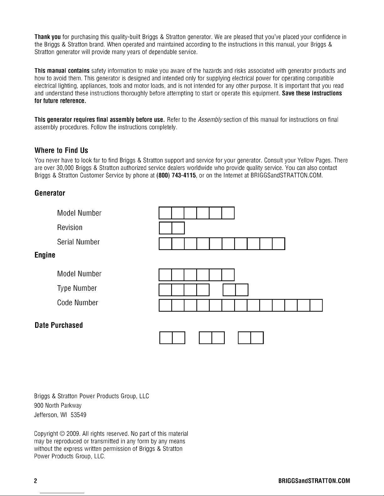
Generator
Model Number
Revision
Serial Number
Engine
Model Number
Type Number
Code Number
DatePurchased
Briggs & Stratton PowerProducts Group, LLC
900 North Parkway
Jefferson, WI 53549
III
III
III III III
Copyright © 2009. All rights reserved.Nopart of this material
may bereproducedor transmitted in any form by any means
without the expresswritten permission of Briggs & Stratton
Power Products Group, LLC.
2 BRIGGSandSTRATTON.COIVl
Page 3
Tableof Contents
Operator Safety ................................. 4
Equipment Description......................................... 4
Safety Rules................................................. 4
Assembly ..................................... 7
UnpackGenerator ............................................ 7
Shipment Contents ........................................... 7
Install Wheel Kit.............................................. 7
Add Engine Oil............................................... 9
Add Fuel.................................................... 9
System Ground ............................................. 10
Connectingto a Building's ElectricalSystem....................... 10
GeneratorLocation .......................................... 10
FeaturesandControls............................ 11
Cord Sets and Receptacles.................................... 13
Ground Fault Protection....................................... 14
Battery Charger............................................. 15
Operation .................................... 16
Starting the Engine .......................................... 16
ConnectingElectrical Loads.................................... 17
Stopping the Engine.......................................... 17
OperatingAutomatic Idle Control................................ 17
Oil PressureShutdown ....................................... 17
Charginga Battery........................................... 17
ColdWeather Operation....................................... 18
Don't OverloadGenerator ..................................... 19
Maintenance .................................. 20
MaintenanceSchedule........................................ 20
GeneratorMaintenance....................................... 20
FuelValveMaintenance....................................... 21
Engine Maintenance.......................................... 21
Storage ................................................... 24
Troubleshooting ................................ 25
Warranties.................................... 28
Emissions ControlSystem Warranty ............................. 28
GeneratorOwnerWarranty .................................... 30
Specifications ................................. 32
Product Specifications........................................ 32
Common Service Parts ....................................... 32
Frangais Espa_ol
(Z3
Page 4
OperatorSafety
Equipment Description
Readthis manualcarefully and becomefamiliar
...... with yourgenerator. Knowits applications, its
limitationsand anyhazardsinvolved.
Thegenerator is an engine-driven, revolvingfield, alternating
current (AC) generator.It was designedto supply electrical
power for operating compatible electrical lighting,
appliances,tools and motor loads. The generator's revolving
field is driven at about 3,600 rpm by a twin-cylinder engine.
This generator incorporates GFCI(Ground FaultCircuit
Interrupter) outlet protection and has its neutral bonded to
ground to comply to OSHAinspections on job sites. This
generatorwill not function when connectedto a 2 pole
transfer switch since the home or building main breakerbox
also has a neutral bonded to ground. When both the
generator andthe home or building breakerbox contains a
neutral bonded to ground, the generators GFCIwill open and
no outlets will function.
_i, WARNING Removingthe neutral bond could result in
'_l_lJ death, bodily injury and/or property damage.
'am,
• DONOTremovetheneutralbond.
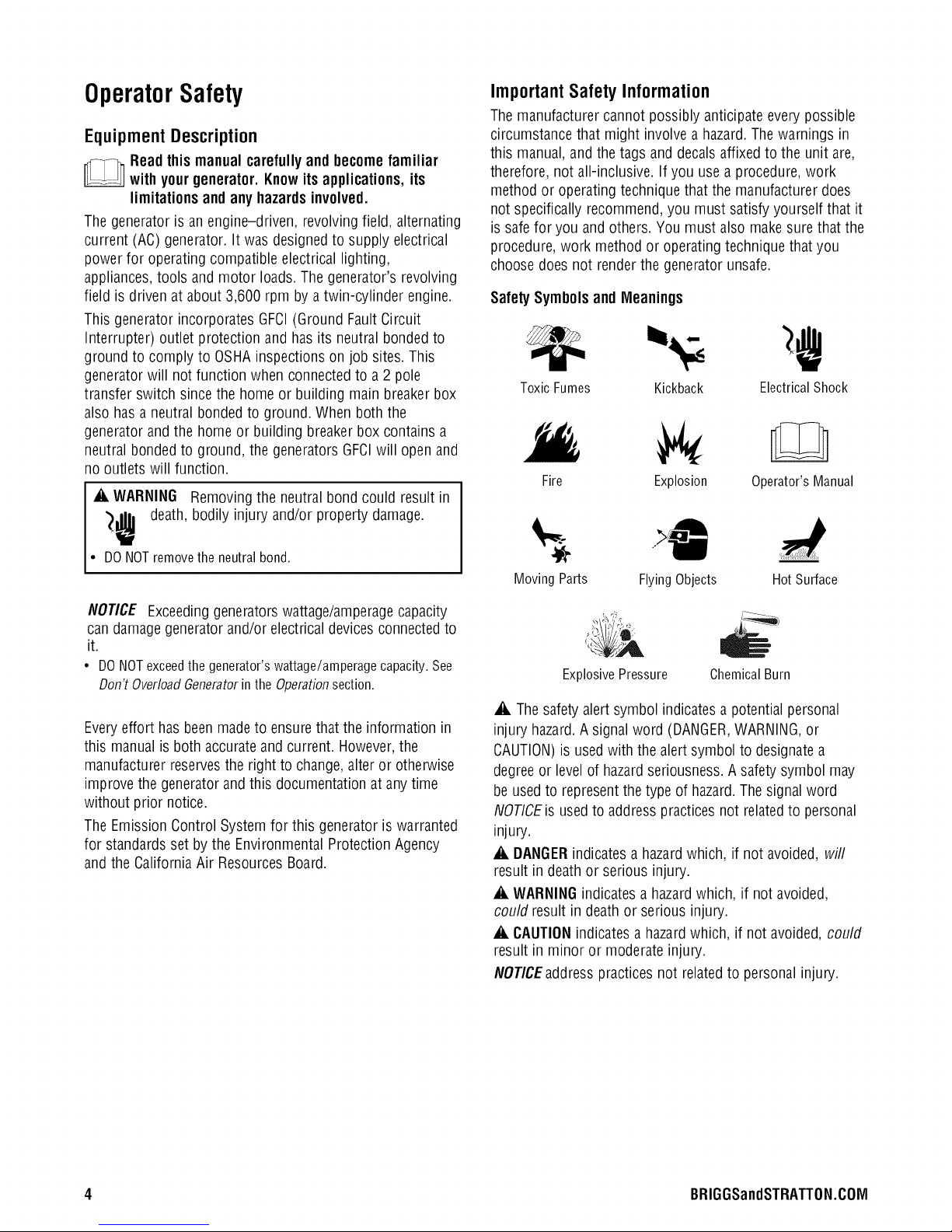
Important Safety Information
Themanufacturer cannot possibly anticipateevery possible
circumstance that might involve a hazard.The warnings in
this manual,and the tags and decals affixed to the unit are,
therefore, not all-inclusive. If you usea procedure,work
method or operating technique that the manufacturer does
not specifically recommend, you must satisfy yourself that it
is safe for you and others. You must also makesure that the
procedure, work method or operating technique that you
choose does not renderthe generator unsafe.
SafetySymbolsand Mleanings
Toxic Fumes Kickback
Fire
Moving Parts FlyingObjects HotSurface
Explosion Operator'sManual
ElectricalShock
NOTICE Exceedinggeneratorswattage/amperagecapacity
candamagegeneratorand/or electricaldevices connectedto
it.
• DONOTexceedthegenerator'swattage/amperagecapacity.See
Don'tOverloadGeneratorintheOperationsection.
Everyeffort has been madeto ensurethat the information in
this manualis both accurateand current. However,the
manufacturer reservesthe right to change,alter or otherwise
improve the generator and this documentationat any time
without prior notice.
The EmissionControl Systemfor this generator is warranted
for standardsset by the Environmental ProtectionAgency
and the California Air Resources Board.
Explosive Pressure
,A The safety alertsymbol indicatesa potential personal
injury hazard.A signalword (DANGER,WARNING,or
CAUTION)is used with the alert symbol to designatea
degreeor levelof hazardseriousness. A safety symbol may
be used to representthe type of hazard.Thesignal word
NOTICEis usedto address practicesnot relatedto personal
injury.
_i, DANGER indicatesa hazardwhich, if not avoided, will
result in deathor serious injury.
_i, WARNINGindicatesa hazardwhich, if not avoided,
could result indeath or serious injury.
_i, CAUTIONindicates a hazardwhich, if not avoided, could
result in minor or moderate injury.
NOTICEaddresspractices not relatedto personal injury.
ChemicalBurn
4 BRIGGSandSTRATTON.COIVl
Page 5
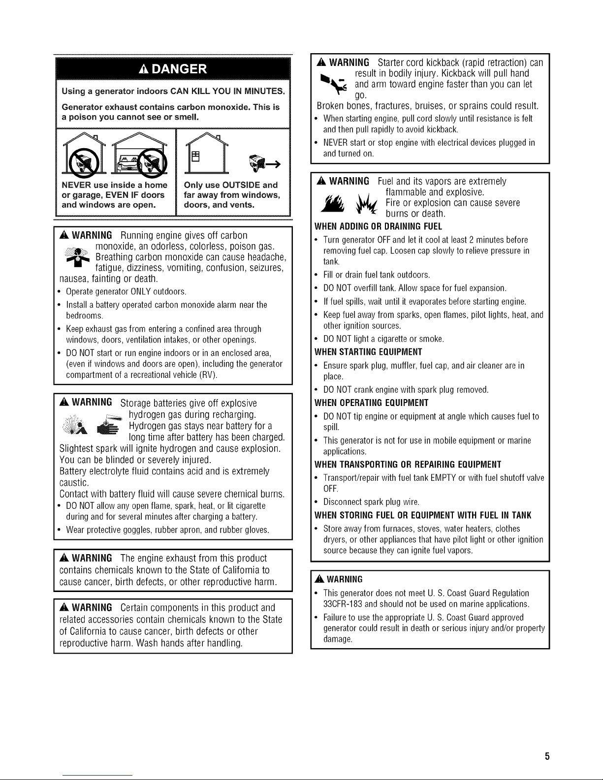
Using a generator indoors CAN KiLL YOU iN MINUTES,
Generator exhaust contains carbon monoxide, This is
a poison you cannot see or smell,
A
_i, WARNING Starter cord kickback (rapid retraction) can
result in bodily injury. Kickback will pull hand
_,_,_ and arm toward engine faster than you can let
go.
Broken bones, fractures, bruises, or sprains could result.
• When starting engine, pull cord slowly until resistanceisfelt
andthen pull rapidly to avoid kickback.
• NEVERstart or stop enginewith electrical devices plugged in
andturned on.
V V
NEVER use inside a home
or garage, EVEN iF doors
and windows are open,
_i, WARNING Running engine gives off carbon
monoxide, an odorless, colorless, poison gas.
Breathing carbon monoxide can cause headache,
fatigue, dizziness, vomiting, confusion, seizures,
nausea, fainting or death.
• Operategenerator ONLY outdoors.
• Install a battery operated carbon monoxide alarm nearthe
bedrooms.
• Keepexhaustgas from entering a confined areathrough
windows, doors,ventilation intakes, or other openings.
• DO NOTstart or run engine indoors or in an enclosedarea,
(even if windows and doors areopen), including the generator
compartment of arecreationalvehicle (RV).
Only use OUTSIDE and
far away from windows,
doors, and vents,
_i, WARNING Storage batteriesgive off explosive
_,il;,_ ,,-_.._.hydrogengas during recharging.
,t_,,_._,, _ Hydrogengasstays nearbatteryfor a
long time after batteryhas beencharged.
Slightest spark will ignite hydrogen and cause explosion.
You can be blinded or severely injured.
Batteryelectrolyte fluid contains acid and is extremely
caustic.
Contactwith batteryfluid will causeseverechemicalburns.
• DONOTallowanyopenflame,spark,heat,or lit cigarette
duringandfor severalminutesaftercharginga battery.
• Wearprotectivegoggles,rubberapron,andrubbergloves.
_i, WARNING Theengine exhaust from this product
contains chemicals known to the State of California to
causecancer, birth defects, or other reproductive harm.
_i, WARNING Certain components in this product and
relatedaccessoriescontain chemicals known to the State
of Californiato causecancer, birth defects or other
reproductive harm. Washhands after handling.
_i, WARNING Fuel and its vapors are extremely
flammable and explosive.
j_, _ Fire or explosion can cause severe
burns or death.
WHENADDINGOR DRAININGFUEL
• Turn generator OFFand let it coolat least2 minutes before
removing fuel cap. Loosen cap slowly to relieve pressure in
tank.
• Fill or drain fuel tank outdoors.
• DONOToverfill tank. Allow spacefor fuel expansion.
• If fuel spills, wait until it evaporatesbefore starting engine.
• Keepfuel awayfrom sparks, open flames, pilot lights, heat,and
other ignition sources.
• DONOTlight a cigaretteor smoke.
WHENSTARTINGEQUIPMENT
• Ensure spark plug, muffler, fuel cap, and air cleanerare in
place.
• DO NOTcrank enginewith spark plug removed.
WHENOPERATINGEQUIPMENT
• DONOTtip engine or equipment at anglewhich causesfuel to
spill.
• This generator is not for use in mobile equipment or marine
applications.
WHENTRANSPORTINGORREPAIRINGEQUIPMENT
• Transport/repair with fuel tank EMPTYor with fuel shutoff valve
OFF.
• Disconnectspark plug wire.
WHENSTORINGFUELOR EQUIPMENTWITH FUELIN TANK
• Store away from furnaces, stoves, water heaters,clothes
dryers, or otherappliancesthat have pilot light or other ignition
source becausethey can ignite fuel vapors.
_i, WARNING
• This generator does not meet U. S. CoastGuard Regulation
33CFR-183and should not be used on marineapplications.
• Failureto usethe appropriate U. S. CoastGuard approved
generator could result in deathor serious injury and/or property
damage.
Page 6
_i, WARNING Generator produces hazardous voltage.
'),111, Failure to isolate generator from power utility
can result in death or injury to electric utility
workers due to backfeed of electrical energy.
• When using generator for backup power, notify utility company.
Use approvedtransfer equipmentto isolategenerator from
electric utility.
• Use a ground fault circuit interrupter (GFCI)in any damp or
highly conductivearea,such as metal decking or steel work.
• DO NOTtouch bare wires or receptacles.
• DO NOTuse generator with electrical cords which areworn,
frayed, bareor otherwise damaged.
• DO NOToperate generator in the rain or wet weather.
• DO NOThandle generator or electricalcords while standing in
water, while barefoot,or while hands or feet are wet.
• DO NOTallow unqualified persons or children to operate or
servicegenerator.
_i, WARNING Contact with muffler area can result in
serious burns.
Exhaust
combustibles, structures or damage
fuel tank causing a fire.
• DO NOTtouch hot parts and AVOID hot exhaust gases.
• Allow equipment to cool beforetouching.
• Keepat least5 feet (152 cm) of clearanceon all sidesof
generator including overhead.
• It is a violation of California Public Resource Code, Section
4442, to use or operatethe engineon anyforest-covered,
brush-covered, or grass-covered land unlessthe exhaust
system is equipped with a spark arrester, as defined in Section
4442, maintained in effective working order. Other states or
federal jurisdictions may havesimilar laws.
Contactthe original equipment manufacturer, retailer, or dealer
to obtain a spark arrester designed for the exhaust system
installed on this engine.
• Replacement parts must bethe sameand installed in the same
position asthe original parts.
heat/gases can ignite
_i, CAUTION Excessively high operating speeds increase
risk of injury and damage to generator.
Excessively low speeds impose a heavy load.
• DO NOTtamper with governedspeed. Generatorsupplies
correct rated frequency andvoltage when running at governed
speed.
• DO NOTmodify generator in any way.
NOTICE Exceeding generators wattage/amperage capacity
can damage generator and/or electrical devices connected to
it.
• DO NOTexceedthe generator's wattage/amperage capacity. See
Don't OverloadGeneratorin the Operationsection.
• Start generator and let engine stabilize beforeconnecting
electrical loads.
• Connectelectrical loads in OFFposition, then turn ONfor
operation.
• Turn electrical loads OFFand disconnect from generator before
stopping generator.
NOTICE Improper treatment of generator can damage it
and shorten its life.
• Use generator only for intendeduses.
• If you havequestions about intended use,ask dealeror contact
local service center.
• Operategenerator only on level surfaces.
• DO NOTexposegenerator to excessivemoisture, dust, dirt, or
corrosive vapors.
• DO NOTinsert any objectsthrough cooling slots.
• If connected devicesoverheat, turn them off anddisconnect them
from generator.
• Shut off generator if:
-electrical output is lost;
-equipment sparks, smokes, or emitsflames;
-unit vibrates excessively.
_i, WARNING Unintentional sparking can result in fire or
_ electric shock.
WHENADJUSTINGOR MAKINGREPAIRSTO YOURGENERATOR
• Disconnectthe spark plugwire from the spark plug and place
the wire where it cannot contact spark plug.
WHENTESTINGFORENGINESPARK
• Use approved spark plug tester.
• DO NOTcheckfor spark with spark plug removed.
_i, WARNING Starter and other rotating parts can
entangle hands, hair, clothing, or accessories.
• NEVERoperategenerator without protective housing or covers.
• DO NOTwear looseclothing, jewelry or anythingthat may be
caught in the starter or other rotating parts.
• Tie up long hairand removejewelry.
6 BRIGGSandSTRATTON.COIVI
Page 7
Assembly
Your generator requiressome assembly andis ready for use
after it hasbeen properly servicedwith the recommended oil
and fuel.
If you haveany problemswith the assemblyof your generator,
pleasecall the generator helplineat 1-808-743-4115. If calling
for assistance,pleasehavethe model,revision,and serial
numberfrom the identificationlabel available.SeeGenerator
ControlsandFeaturesfor identificationlabellocation.
UnpackGenerator
1. Set the carton on a rigid, flat surface.
2. Remove everything from carton exceptgenerator.
3. Opencarton completely by cutting each corner from
top to bottom.
4. Leave generatoron carton to install wheel kit.
Install Wheel Kit
NOTE:Wheel kit is not intended for over-the-road use.
You will needthe following tools to install these
components:
• 3/8" and 13 mm wrench
• Socketwrench with a 3/8" and 13 mm socket
• Pliers
• Safetyglasses
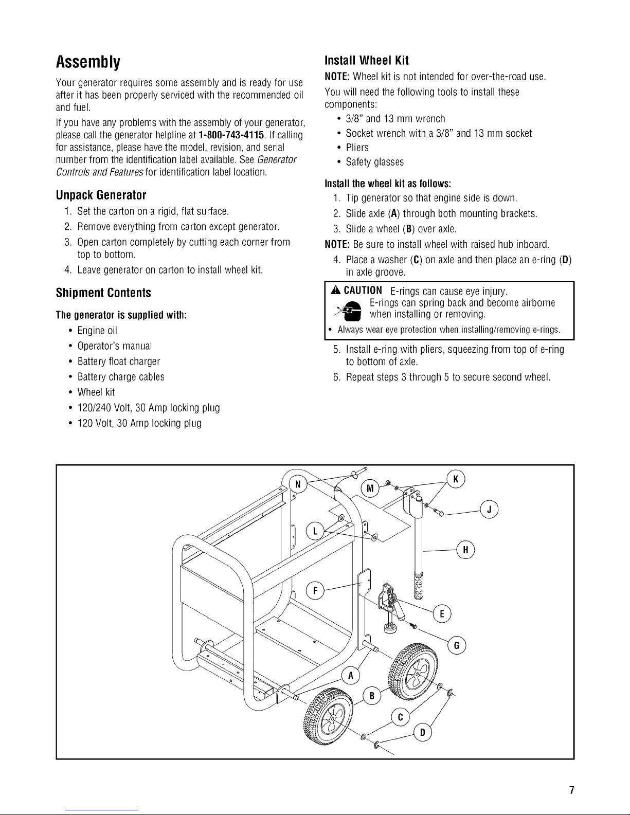
Installthewheelkit asfollows:
1. Tip generator so that engine side is down.
2. Slide axle (A) through both mounting brackets.
3. Slide a wheel (B) over axle.
NOTE:Besure to install wheelwith raised hub inboard.
4. Place a washer (C) on axleand then placean e-ring (D)
in axlegroove.
Shipment Contents
The generatoris suppliedwith:
• Engineoil
• Operator's manual
• Batteryfloat charger
• Batterychargecables
• Wheelkit
• 120/240 Volt, 30 Amp locking plug
• 120Volt, 30 Amp locking plug
_i, CAUTION E-rings can causeeye injury.
E-rings can spring back and become airborne
when installing or removing.
• Alwaysweareyeprotectionwheninstalling/removinge-rings.
5. Install e-ring with pliers, squeezingfrom top of e-ring
to bottom of axle.
6. Repeatsteps 3 through 5 to secure secondwheel.
Page 8

7. Tipgeneratorsothatengineendisup.
8. Attachclamps(E)tobrackets(F)onbothsidesof
generatorwith1/4-20hexscrews(G).
9. Repeatsteps2through5tosecurethethirdandfourth
wheels.
10.Attachhandles(H)tobracketsongeneratorframeas
shown,with45mmcapscrews(J),flatwashers(K),
nylonwashers(L),andM8locknuts(M).
NOTE:DONOTovertighten. Handlesmust be able to move
up and down freely.
11. Return generator to normal operating position (resting
on wheels).
12. To apply brakes,push down firmly on handle of both
clamps until it locks in the down position and engages
the wheels.
IMPORTANT:The generator is designedto be used on level
surfaces.
13. Loop handle pins (N) ongenerator frame just above
handle brackets.
14. Raise handlesand insert handle pins to move
generator.
15. To release brakes, pull up onhandle of both clamps
until it locks in the up position.
Attach Negative Battery Cable
Your unit is equippedwith electric start capability but can be
started manually. If you choose not to use the electric start
feature,you do not needto connect the negative battery
cable.
Thesealedbattery on the generator pre-installed except for
the negative (black) batterycable.
_i, WARNING Batteryposts,terminals and related
accessoriescontain leadand leadcompounds - chemicals
known to the State of Californiato cause cancerand
reproductiveharm. Wash handsafter handling.
To install:
1. Cut off tie wrap securing looseend of negative (black)
cable.
2. Using an 8 mm or 5/16" socketwrench, remove
screw (A), lock washer (B)and flat washer (C)on
negative batteryterminal.
©
3. Slide lock washer, flat washer and negativebattery cable
(D) over screw as shown.
4. Reattachscrew to negativebattery terminal and tighten.
5. Verify that connections to battery and generator are
tight and secure.
NOTE:If your battery is discharged, charge prior to use
following the instructions in the section Battery Charger.
8 BRIGGSandSTRATTON.COIVl
Page 9
Add Engine Oil
1. Place generatoron a flat, level surface.
2. Cleanarea around oil fill and removeyellow oil fill cap.
3. Using oil funnel (optional), slowly pour contents of
both provided oil bottles into oil fill opening to the
"Full" mark on dipstick.
NOTICE Improper treatment of generator can damage it
and shorten its life.
• DO NOTattempt to crank or start the engine before it has been
properly servicedwith the recommended oil. This may result in an
enginefailure.
4. Replaceoil fill cap and fully tighten.
Add Fuel
Fuel must meet theserequirements:
• Clean,fresh, unleadedgasoline.
• A minimum of 87 octane/87AKI (91 RON).For high
altitude use, seeHigh Altitude.
• Gasolinewith up to 10% ethanol (gasohol) or up to
15% MTBE(methyl tertiary butyl ether) is acceptable.
_i, WARNING Fueland its vapors are extremely
flammable and explosive.
_, _ Fireor explosion can causesevere
burns or death.
WHENADDINGFUEL
• Turn generator OFFand let it cool at least 2 minutes before
removing fuel cap. Loosen cap slowly to relieve pressure in
tank.
• Fill fuel tank outdoors.
• DONOToverfill tank. Allow spacefor fuel expansion.
• If fuel spills, wait until it evaporatesbefore starting engine.
• Keepfuel awayfrom sparks, open flames, pilot lights, heat,and
other ignition sources.
• DONOTlight a cigaretteor smoke.
,
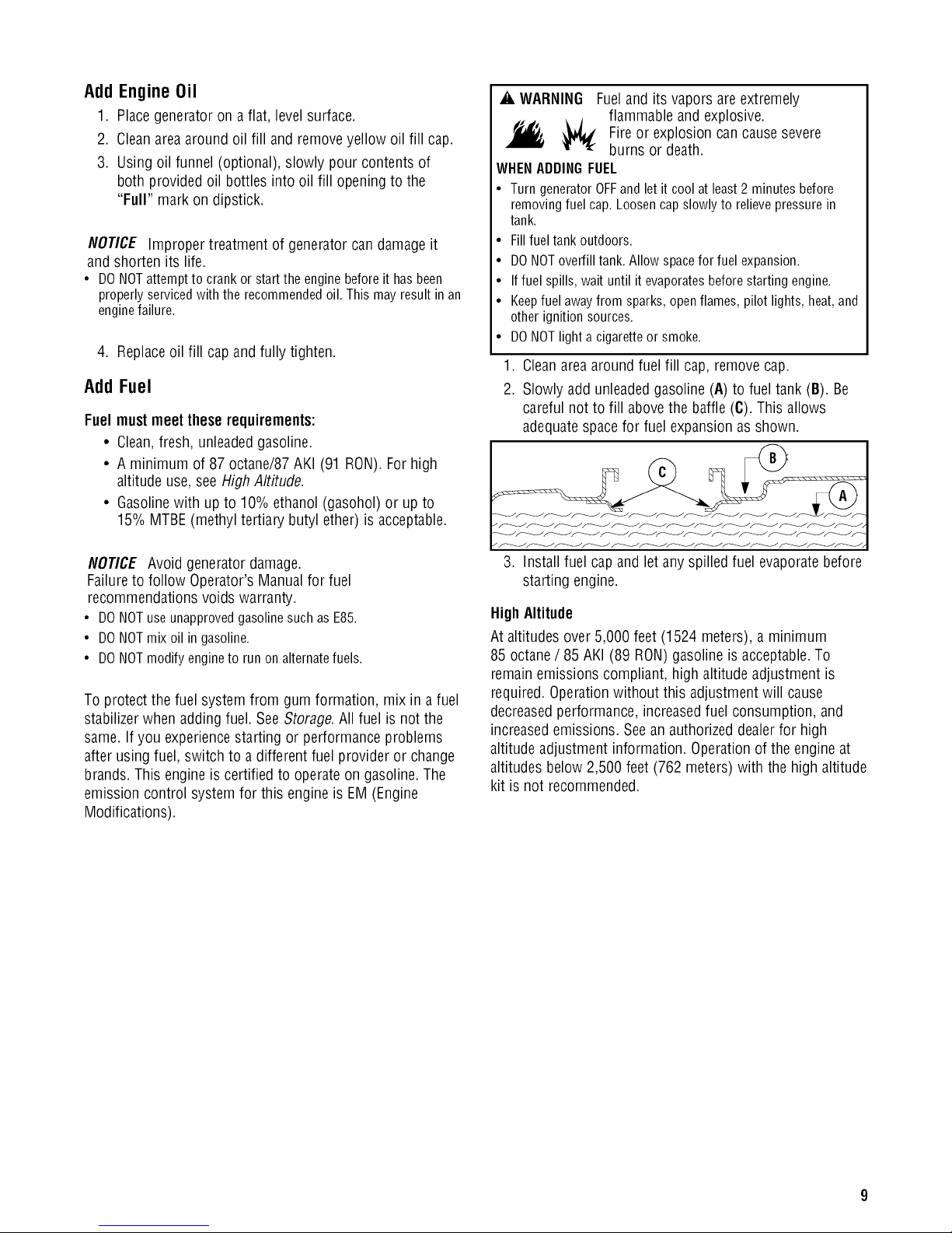
Cleanarea around fuel fill cap, removecap.
2.
Slowly addunleadedgasoline (A) to fuel tank (B). Be
careful not to fill abovethe baffle (C). This allows
adequatespace for fuel expansion asshown.
NOTICE Avoid generatordamage.
Failureto follow Operator's Manual for fuel
recommendations voids warranty.
• DONOTuseunapprovedgasolinesuchasE85.
• DONOTmixoil in gasoline.
• DONOTmodifyengineto runonalternatefuels.
To protect the fuel system from gum formation, mix in a fuel
stabilizerwhen adding fuel. SeeStorage.All fuel is not the
same. If you experiencestarting or performanceproblems
after using fuel, switch to a different fuel provider or change
brands. This engine is certified to operateon gasoline.The
emission control system for this engine is EM (Engine
Modifications).
3. Install fuel capand let anyspilled fuel evaporatebefore
starting engine.
High Altitude
At altitudes over 5,000 feet (1524 meters), a minimum
85 octane/ 85 AKI (89 RON)gasoline is acceptable.To
remainemissions compliant, high altitude adjustment is
required.Operationwithout this adjustment will cause
decreasedperformance, increasedfuel consumption, and
increasedemissions. Seeanauthorized dealerfor high
altitude adjustment information. Operationof the engine at
altitudes below 2,500 feet (762 meters) with the high altitude
kit is not recommended.
Page 10
SystemGround
Thegenerator hasa system ground that connects the
generatorframe components to the ground terminals on the
ACoutput receptacles.Thesystem ground is connected to
the ACneutral wire (the neutral is bonded to the generator
frame).
Special Requirements
Theremay be Federalor StateOccupationalSafety and
Health Administration (OSHA)regulations, local codes, or
ordinances that applyto the intended use of the generator.
Pleaseconsult a qualified electrician, electrical inspector, or
the local agency havingjurisdiction:
• In some areas,generators are requiredto be registered
with local utility companies.
• If the generator is usedat a construction site, there
may beadditional regulations which must beobserved.
Connecting to a Building's Electrical System
Connectionsfor standby power to a building's electrical
system must be made by a qualified electrician. The
connection must isolate the generator powerfrom utility
power or other alternativepower sources and must comply
with all applicablelaws and electrical codes.
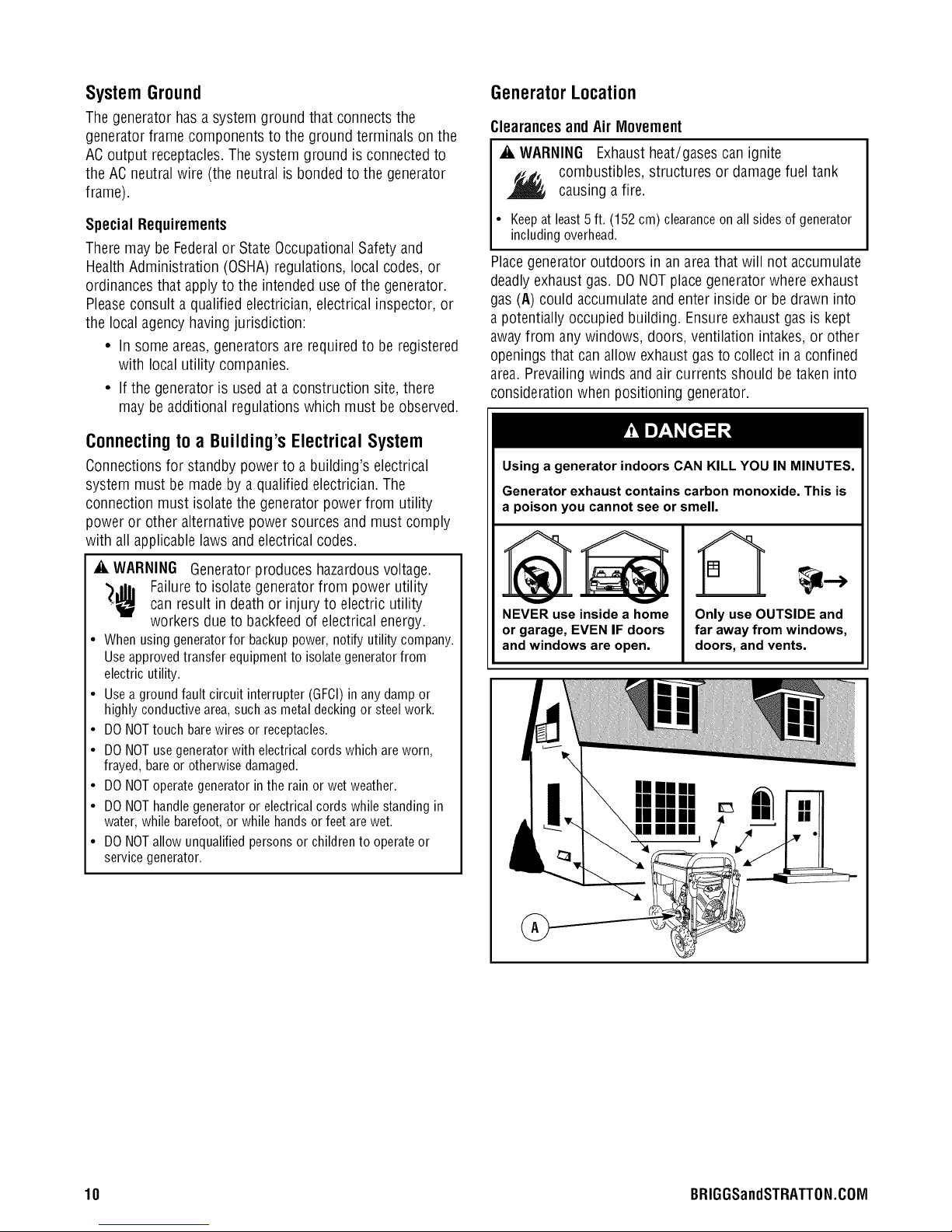
GeneratorLocation
Clearancesand Air Mlovement
_i, WARNING Exhaustheat/gases can ignite
combustibles, structures or damagefuel tank
causing a fire.
• Keepat least5 ft. (152 cm) clearanceon all sides of generator
including overhead.
Placegenerator outdoors in an areathat will not accumulate
deadlyexhaust gas. DO NOTplacegenerator where exhaust
gas (A) could accumulate and enter inside or be drawn into
a potentially occupied building. Ensureexhaustgas is kept
awayfrom any windows, doors, ventilation intakes,or other
openings that canallow exhaustgasto collect in a confined
area.Prevailingwinds and air currents should betaken into
consideration when positioning generator.
Using a generator indoors CAN KILL YOU IN MINUTES.
Generator exhaust contains carbon monoxide. This is
a poison you cannot see or smell.
_i, WARNING Generatorproduces hazardousvoltage.
")J|h Failureto isolate generatorfrom power utility
can result in deathor injury to electric utility
workers due to backfeedof electrical energy.
• Whenusinggeneratorfor backuppower,notifyutilitycompany.
Useapprovedtransferequipmentto isolategeneratorfrom
electricutility.
• Useagroundfaultcircuitinterrupter(GFCI)in anydampor
highlyconductivearea,suchasmetaldeckingor steelwork.
• DONOTtouchbarewiresor receptacles.
• DONOTusegeneratorwithelectricalcordswhichareworn,
frayed,bareorotherwisedamaged.
• DONOToperategeneratorintherainorwetweather.
• DONOThandlegeneratoror electricalcordswhilestandingin
water,whilebarefoot,or whilehandsorfeetarewet.
• DONOTallowunqualifiedpersonsor childrento operateor
servicegenerator.
NEVER use inside a home
or garage, EVEN IF doors
and windows are open.
U!
Hi II I
!
Only use OUTSIDE and
far away from windows,
doors, and vents.
10 BRIGGSandSTRATTON.COIVl
Page 11
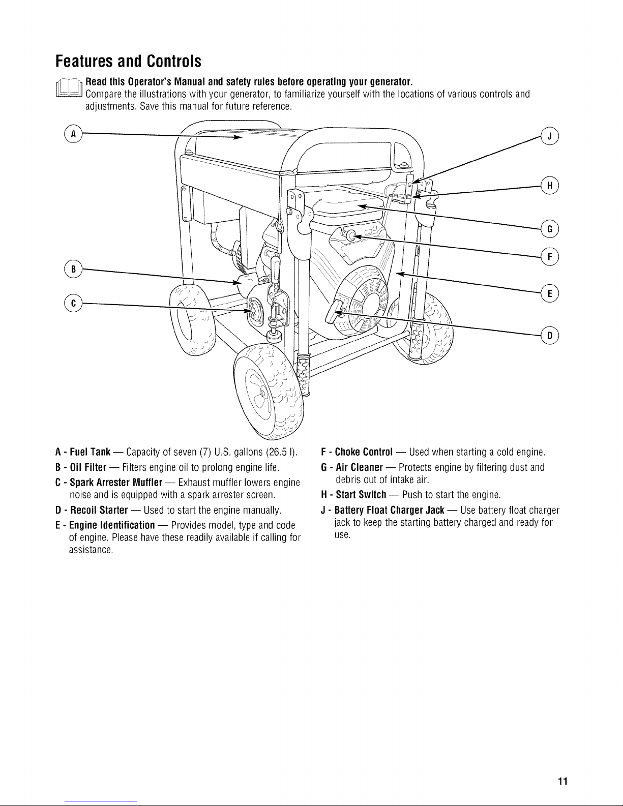
FeaturesandControls
Readthis Operator'sManualand safetyrules beforeoperatingyourgenerator.
Comparethe illustrations with your generator, to familiarize yourself with the locations of various controls and
adjustments. Save this manual for future reference.
A- FuelTank -- Capacityof seven (7) U.S.gallons (26.5 I).
B- 0il Filter -- Filters engineoil to prolong enginelife.
C- Spark AttesterMuffler -- Exhaustmuffler lowers engine
noiseand is equippedwith a spark arrester screen.
D - Recoil Starter -- Usedto start the engine manually.
E - Engine Identification -- Provides model, type and code
of engine. Pleasehavethese readily availableif calling for
assistance.
F - ChokeControl-- Usedwhen starting a cold engine.
G - AirCleaner-- Protects engine by filtering dust and
debris out of intake air.
H - Start Switch -- Pushto start the engine.
J - BatteryFloat ChargerJack -- Usebatteryfloat charger
jack to keep the starting battery chargedand ready for
use.
11
Page 12
/
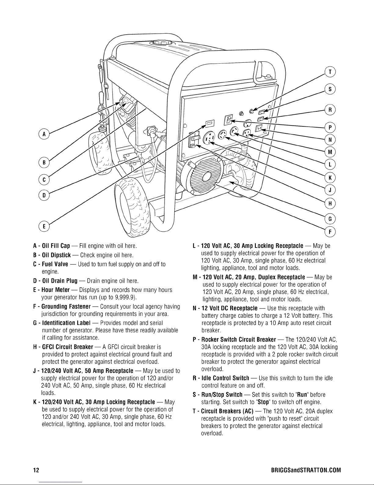
A- Oil Fill Cap-- Fill enginewith oil here.
B- 0il Dipstick-- Checkengineoil here.
C- Fuel Valve -- Usedto turn fuel supply on and off to
engine.
D - Oil DrainPlug-- Drainengine oil here.
E - HourMeter -- Displaysand records how many hours
your generator has run (up to 9,999.9).
F - GroundingFastener-- Consultyour local agency having
jurisdiction for grounding requirements inyour area.
G - IdentificationLabel-- Provides model and serial
number of generator. Pleasehave these readily available
if calling for assistance.
H - GFCICircuit Breaker-- A GFCIcircuit breakeris
provided to protect against electrical ground fault and
protect the generator against electrical overload.
J - 120/240 Volt AC, 50 Amp Receptacle -- Maybe used to
supply electrical power for the operation of 120 and/or
240 Volt AC,50 Amp, single phase,60 Hzelectrical
loads.
K- 120/240 Volt AC, 30 Amp LockingReceptacle -- May
be used to supply electrical powerfor the operation of
120 and/or 240 Volt AC, 30 Amp, single phase, 60 Hz
electrical, lighting, appliance, tool and motor loads.
L - 120 Volt AC, 30 Amp Locking Receptacle-- May be
usedto supply electrical powerfor the operation of
120 Volt AC,30 Amp, single phase,60 Hz electrical
lighting, appliance, tool and motor loads.
M - 120 Volt AC, 20 Amp, DuplexReceptacle -- May be
usedto supply electrical powerfor the operation of
120 Volt AC, 20 Amp, single phase,60 Hzelectrical,
lighting, appliance,tool and motor loads.
N - 12Volt DCReceptacle -- Usethis receptaclewith
battery chargecables to charge a 12 Volt battery. This
receptacleis protected by a 10 Amp auto resetcircuit
breaker.
P - RockerSwitch CircuitBreaker-- The120/240 Volt AC,
30A locking receptacleand the 120 Volt AC, 30A locking
receptacleis provided with a 2 pole rocker switch circuit
breakerto protect the generatoragainstelectrical
overload.
FI- Idle ControlSwitch-- Usethis switch to turn the idle
control feature on and off.
S - Run/StopSwitch-- Setthis switch to "Run"before
starting. Set switch to "Stop"to switch off engine.
T - CircuitBreakers(AC)-- The 120Volt AC, 20A duplex
receptacleis provided with "pushto reset"circuit
breakersto protect the generator againstelectrical
overload.
12 BRIGGSandSTRATTON.COIVl
Page 13
CordSetsandReceptacles
Use only high quality, well-insulated, grounded extension
cords with the generator's 120 Volt duplex receptacle.
Inspect extension cords before eachuse.
Checkthe ratings of all extensioncords beforeyou use
them. Extensioncord sets usedshould be ratedfor 125 Volt
ACloads at 20 Amps or greaterfor most electrical devices.
Somedevices, however, may not require this type of
extension cord. Checkthe operator's manuals of those
devicesfor the manufacturer's recommendations.
Keepextension cords asshort aspossible to minimize
voltage drop.
_k WARNING Overloadedelectrical cords can overheat,
arc, andburn resulting in death, bodily injury,
and/or property damage.
• ONLYusecordsratedfor your loads.
• Followallsafetiesonelectricalcords.
120/240 Volt AC, 50 Amp Receptacle
Use a NEIVIA14-50 plug with this receptacle.Connect a
4-wire cord set ratedfor 250 Volt AC loadsat 50 Amps to
the plug.
240 Volts AC
RE7 "m
FrameGround
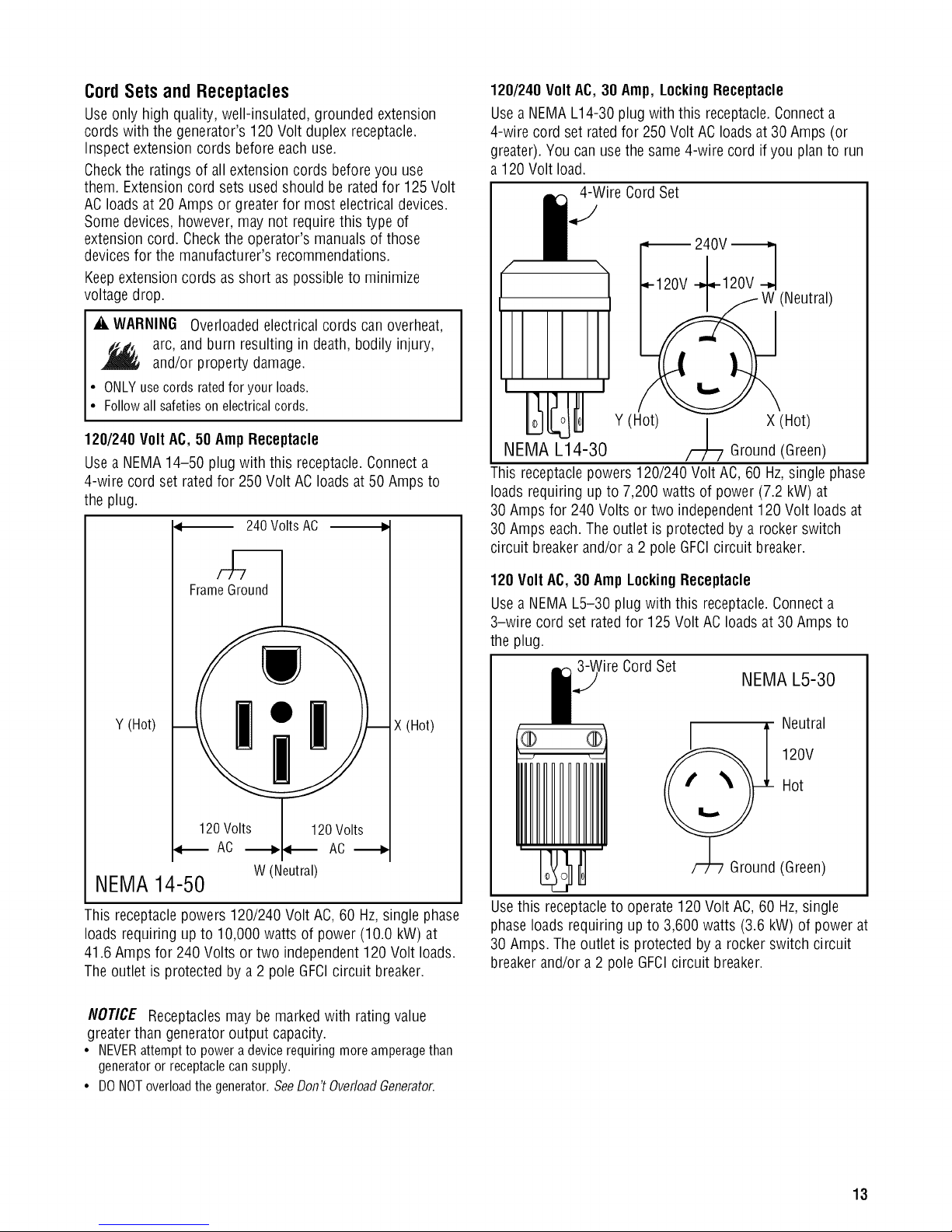
120/240 Volt AC, 30 Amp, LockingReceptacle
Usea NEIVIAL14-30 plug with this receptacle.Connecta
4-wire cord set ratedfor 250 Volt ACloads at 30Amps (or
greater). You can usethe same4-wire cord if you planto run
a 120 Volt load.
4-Wire Cord Set
__11
20V 240V"_
W (Neutral)
Y (Hot) | X (Hot)
NEMA L14-30 /--/L 7 Ground (Green)
This receptaclepowers 120/240 Volt AC, 60 Hz,single phase
loads requiring up to 7,200 watts of power (7.2 kW) at
30 Amps for 240 Volts or two independent120 Volt loads at
30 Amps each.The outlet is protected by a rocker switch
circuit breakerand/or a 2 pole GFCIcircuit breaker.
120 Volt AC, 30 Amp LockingReceptacle
Usea NEIVIAL5-30 plug with this receptacle.Connecta
3-wire cord set rated for 125 Volt ACloads at 30 Amps to
the plug.
_'ireCord Set
NEMA L5-30
Y (Hot)
AC -_ AC
W(Neutral)
X (Hot)
NEMA14-50
This receptaclepowers 120/240 Volt AC, 60 Hz,single phase
loads requiring up to 10,000 watts of power (10.0 kW) at
41.6 Amps for 240 Volts or two independent 120 Volt loads.
Theoutlet is protected by a 2 poleGFCIcircuit breaker.
NOTICE Receptacles may be marked with rating value
greater than generator output capacity.
• NEVERattempt to power a device requiring more amperagethan
generator or receptaclecan supply.
• DONOToverloadthe generator.SeeDon't OverloadGenerator.
Neutral
® ®
120V
Hot
II11111111111
(Green)
Usethis receptacleto operate 120Volt AC, 60 Hz, single
phaseloads requiring up to 3,600 watts (3.6 kW) of power at
30 Amps. The outlet is protected bya rocker switch circuit
breakerand/or a 2 pole GFCIcircuit breaker.
13
Page 14
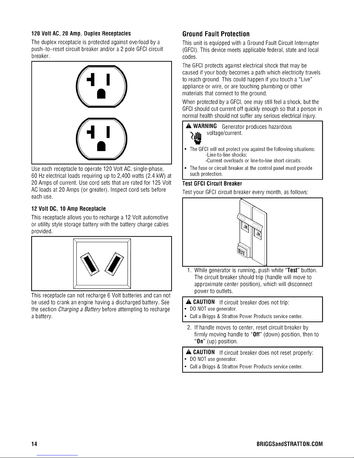
120 VoltAC, 20Amp, DuplexReceptacles
Theduplex receptacleis protected againstoverload by a
push-to-reset circuit breaker and/or a 2 pole GFCIcircuit
breaker.
Use each receptacleto operate 120 Volt AC, single-phase,
60 Hzelectrical loads requiring up to 2,400 watts (2.4 kW) at
20 Amps of current. Usecord setsthat are ratedfor 125 Volt
ACloads at 20 Amps (or greater). Inspect cord sets before
eachuse.
Ground Fault Protection
This unit is equippedwith a Ground Fault Circuit Interrupter
(GFCI).This device meets applicable federal, stateand local
codes.
TheGFCIprotects against electrical shock that may be
caused if your body becomesa pathwhich electricity travels
to reachground. This could happen if you touch a "Live"
applianceor wire, or are touching plumbing or other
materials that connectto the ground.
Whenprotectedby a GFCI,onemaystill feela shock, but the
GFCIshould cut current off quickly enough sothat a personin
normal healthshould notsuffer any seriouselectricalinjury.
_i, WARNING Generatorproduces hazardous
_ voltage/current.
• TheGFCIwill notprotectyou againstthefollowingsituations:
-Line-to-lineshocks;
-Currentoverloadsor line-to-lineshortcircuits.
• Thefuseorcircuit breakerat thecontrolpanelmustprovide
suchprotection.
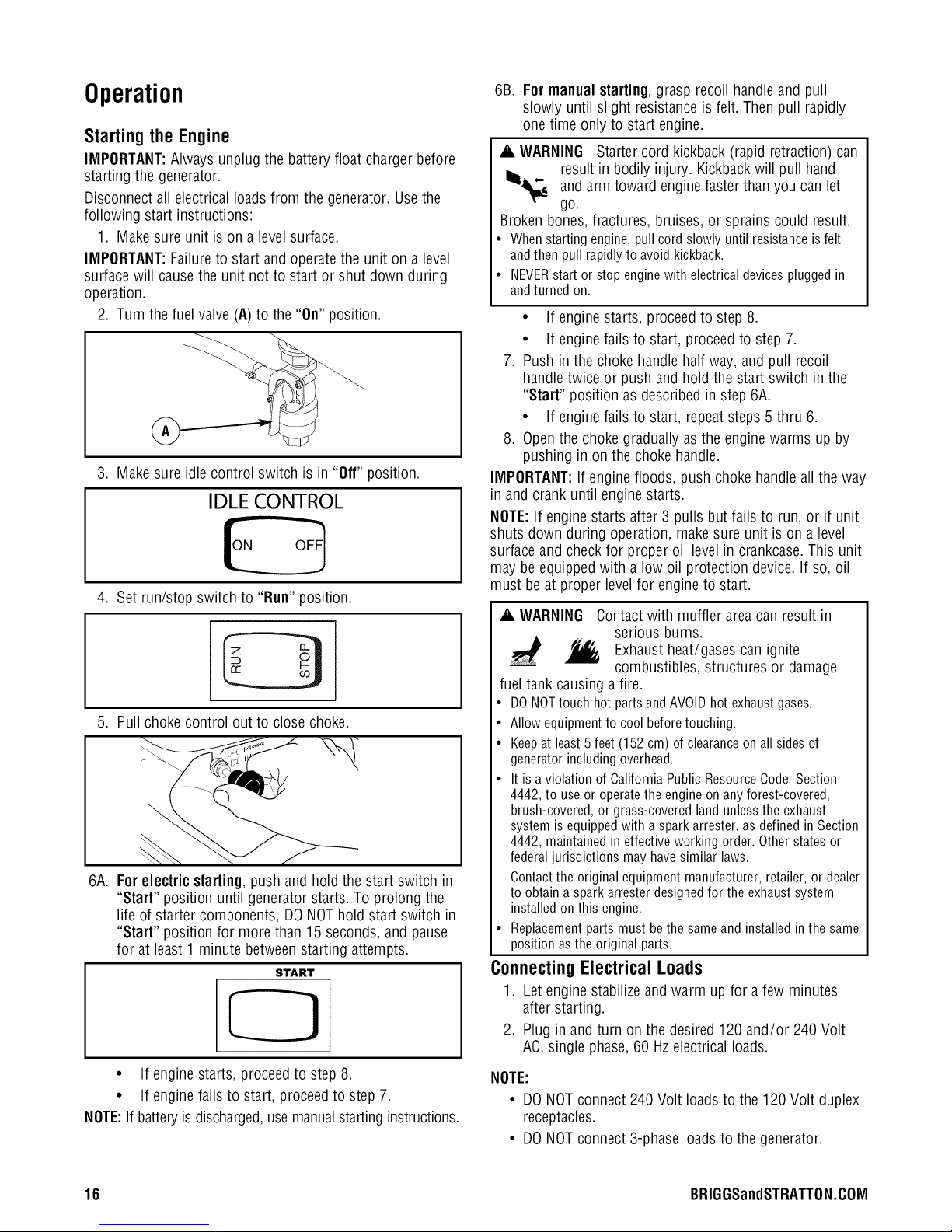
TestGFCICircuit Breaker
Testyour GFCIcircuit breakerevery month, as follows:
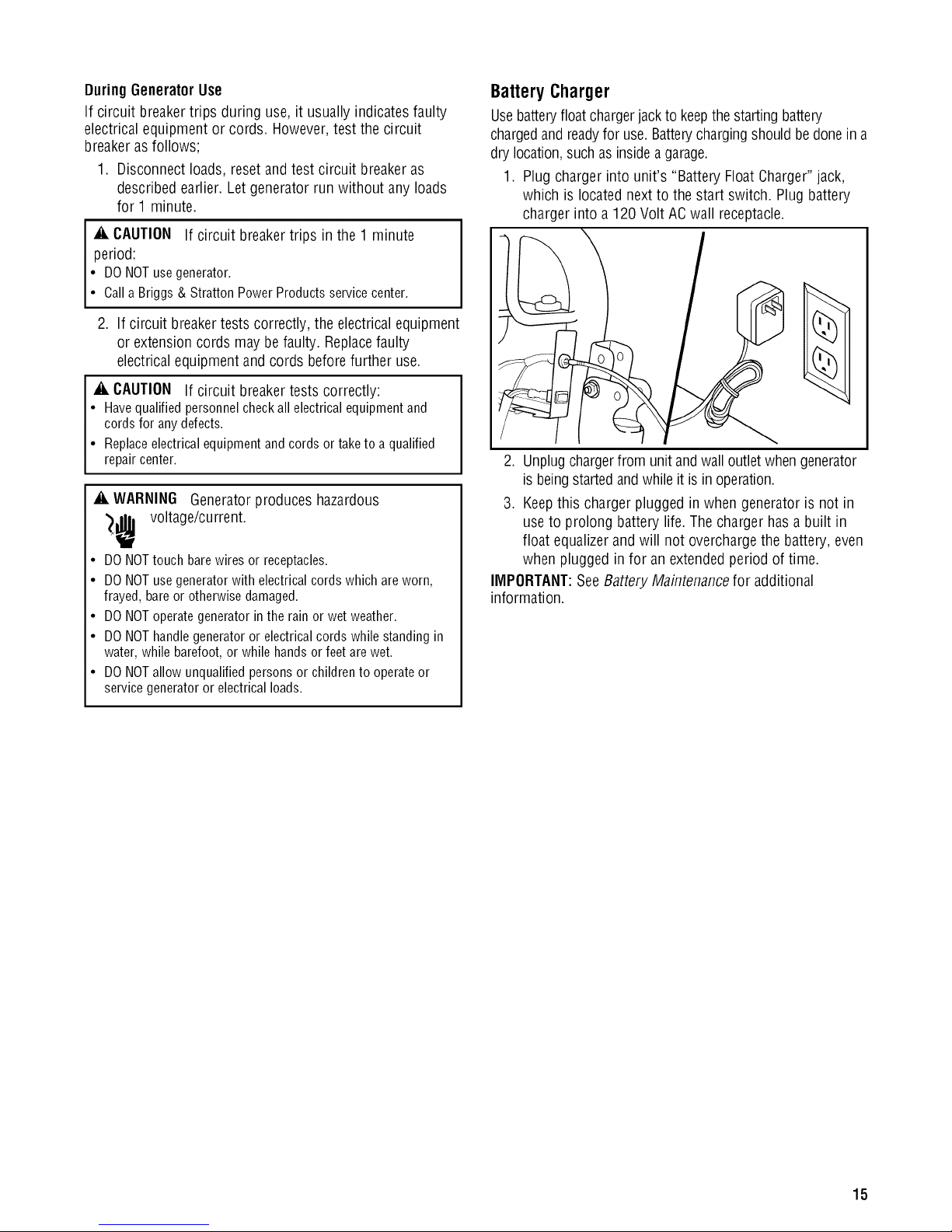
12 Volt DC,10 Amp Receptacle
This receptacleallows you to rechargea 12 Volt automotive
or utility style storage batterywith the battery chargecables
provided.
This receptaclecan not recharge 6 Volt batteriesand can not
be used to crank an engine having adischarged battery. See
the section Charginga Batterybefore attempting to recharge
a battery.
1. While generator is running, push white "Test" button.
Thecircuit breaker should trip (handle will move to
approximate center position), which will disconnect
power to outlets.
_i, CAUTION If circuit breaker does not trip:
• DO NOTuse generator.
• Calla Briggs & Stratton Power Products servicecenter.
2. If handlemoves to center, resetcircuit breakerby
firmly moving handleto "Off" (down) position, then to
"On" (up) position.
_i, CAUTION If circuit breaker does not reset properly:
• DO NOTuse generator.
• Calla Briggs & Stratton Power Products servicecenter.
14 BRIGGSandSTRATTON.COIVI
Page 15
DuringGenerator Use
If circuit breakertrips during use, it usually indicatesfaulty
electrical equipment or cords. However,test the circuit
breakerasfollows;
1. Disconnect loads, reset and test circuit breakeras
described earlier. Let generator runwithout any loads
for 1 minute.
_i, CAUTION If circuit breakertrips in the 1 minute
period:
• DONOTusegenerator.
• CallaBriggs& StrattonPowerProductsservicecenter.
2. If circuit breakertests correctly, the electricalequipment
or extensioncords may be faulty. Replacefaulty
electricalequipment and cords beforefurther use.
_i, CAUTION If circuit breaker tests correctly:
• Havequalified personnel checkall electricalequipment and
cords for any defects.
• Replaceelectrical equipment and cords or take to a qualified
repair center.
_i, WARNING Generator produces hazardous
_lr voltage/current.
• DO NOTtouch bare wires or receptacles.
• DO NOTuse generator with electrical cords which areworn,
frayed, bareor otherwise damaged.
• DO NOToperate generator in the rain or wet weather.
• DO NOThandle generator or electricalcords while standing in
water, while barefoot,or while hands or feet are wet.
• DO NOTallow unqualified persons or children to operate or
servicegenerator or electrical loads.
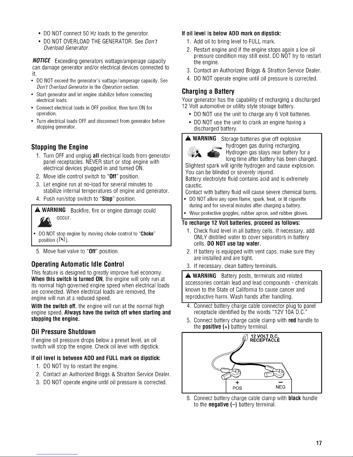
BatteryCharger
Usebatteryfloat chargerjackto keepthe starting battery
chargedand readyfor use.Batterychargingshouldbedone in a
dry location,such asinsidea garage.
1. Plug charger into unit's "Battery Float Charger"jack,
which is locatednext to the start switch. Plug battery
charger into a 120 Volt AC wall receptacle.
2. Unplug chargerfrom unit andwall outletwhengenerator
is beingstartedand while it is inoperation.
3. Keepthis charger plugged in when generator is not in
useto prolong battery life. The chargerhas a built in
float equalizer and will not overchargethe battery, even
when plugged infor an extended period of time.
IMPORTANT:SeeBattery Maintenancefor additional
information.
15
Page 16
Operation
Starting the Engine
IMPORTANT:Always unplug the battery float charger before
starting the generator.
Disconnect all electrical loads from the generator. Usethe
following start instructions:
1. Make sure unit is on a levelsurface.
IMPORTANT:Failureto start and operate the unit on a level
surfacewill causethe unit not to start or shut down during
operation.
2. Turn the fuel valve(A) to the "On" position.
3. Make sure idle control switch is in "Off" position.
IDLE CONTROL
4. Set run/stop switch to "Nun"position.
5. Pull choke control out to close choke.
6A.
Forelectricstarting,push andhold the start switch in
"Start" position until generator starts. To prolong the
life of starter components, DONOThold start switch in
"Start" position for more than 15 seconds, and pause
for at least 1 minute betweenstarting attempts.
START
6B. For manual starting, grasp recoil handle and pull
slowly until slight resistance is felt. Then pull rapidly
one time only to start engine.
_i, WARNING Starter cord kickback (rapid retraction) can
result in bodily injury. Kickbackwill pull hand
III_ andarm toward enginefasterthan you can let
go.
Brokenbones,fractures, bruises, or sprains could result.
• Whenstartingengine,pullcordslowlyuntil resistanceisfelt
andthenpull rapidlyto avoidkickback.
• NEVERstartor stopenginewith electricaldevicespluggedin
andturnedon.
• If engine starts, proceedto step 8.
• If engine fails to start, proceed to step 7.
7. Push in the choke handle half way, andpull recoil
handle twice or push and hold the start switch in the
"Start" position as described in step6A.
• If engine fails to start, repeat steps 5 thru 6.
8. Openthe choke gradually asthe enginewarms up by
pushing in on the choke handle.
IMPORTANT:If engine floods, push choke handleall the way
in andcrank until engine starts.
NOTE:If engine starts after 3 pulls but fails to run, or if unit
shuts down during operation, makesure unit is on a level
surface and check for proper oil level in crankcase.This unit
may beequippedwith a low oil protection device.If so, oil
must be at proper level for engine to start.
_i, WARNING Contact with muffler area can result in
serious burns.
Exhaust heat/gases can ignite
combustibles, structures or damage
fuel tank causing a fire.
• DO NOTtouch hot parts and AVOIDhot exhaust gases.
• Allow equipmentto cool before touching.
• Keepat least5 feet (152 cm) of clearanceon all sides of
generator including overhead.
• It is a violation of California Public Resource Code,Section
4442, to use or operatethe engine on any forest-covered,
brush-covered, or grass-covered land unless the exhaust
system is equipped with a spark arrester, as defined in Section
4442, maintained in effective working order. Other states or
federaljurisdictions may have similar laws.
Contactthe original equipment manufacturer, retailer, or dealer
to obtain aspark arrester designedfor the exhaust system
installed on this engine.
• Replacement parts must bethe sameand installed in the same
position asthe original parts.
Connecting Electrical Loads
1. Let engine stabilizeand warm up for a few minutes
after starting.
2. Plug in and turn on the desired 120 and/or 240 Volt
AC,single phase,60 Hzelectrical loads.
• If enginestarts, proceedto step 8.
• If enginefails to start, proceed to step 7.
NOTE:If batteryis discharged,usemanualstarting instructions.
16 BRIGGSandSTRATTON.COIVl
NOTE:
• DONOTconnect 240 Volt loadsto the 120 Volt duplex
receptacles.
• DONOTconnect 3-phaseloads to the generator.
Page 17
• DONOTconnect 50 Hzloads to the generator.
• DONOTOVERLOADTHEGENERATOR.SeeDon't
OverloadGenerator.
NOTICE Exceeding generators wattage/amperage capacity
can damage generator and/or electrical devices connected to
it.
• DO NOTexceedthe generator's wattage/amperage capacity. See
Don't OverloadGeneratorin the Operationsection.
• Start generator and let engine stabilize beforeconnecting
electrical loads.
• Connectelectrical loads in OFFposition, then turn ONfor
operation.
• Turn electrical loads OFFand disconnectfrom generator before
stopping generator.
Stoppingthe Engine
1. Turn OFFand unplug all electrical loads from generator
panel receptacles.NEVERstartor stop enginewith
electrical devicesplugged inand turned ON.
2. Move idle control switch to "Off" position.
3. Let engine run at no-loadfor severalminutes to
stabilize internaltemperatures of engineand generator.
4. Push run/stop switch to "Stop" position.
_i, WARNING Backfire,fire or engine damagecould
occur.
• DONOTstopenginebymovingchokecontrolto "Choke"
position(1",I).
5. Move fuel valve to "Off" position.
Operating Automatic Idle Control
This feature is designedto greatly improve fuel economy.
When this switch is turned ON,the engine will only run at
its normal high governed engine speedwhen electrical loads
are connected.When electrical loads are removed,the
engine will run at a reducedspeed.
With the switchoff, the enginewill run at the normal high
engine speed.Alwayshavethe switchoff whenstartingand
stoppingthe engine.
Oil Pressure Shutdown
If engineoil pressuredrops below apreset level,an oil
switch will stop the engine. Checkoil levelwith dipstick.
If oil level isbelowADDmark on dipstick:
1. Add oil to bring levelto FULLmark.
2. Restart engine and if the engine stops again a low oil
pressure condition may still exist. DONOTtry to restart
the engine.
3. Contact an Authorized Briggs & Stratton Service Dealer.
4. DO NOToperateengine until oil pressure is corrected.
Charging a Battery
Your generator has the capability of recharginga discharged
12 Volt automotive or utility style storage battery.
• DONOTusethe unit to charge any 6 Volt batteries.
• DONOTusethe unit to crank an engine havinga
discharged battery.
_i, WARNING Storage batteriesgive off explosive
,-- hydrogen gasduring recharging.
1:_,_ _ Hydrogengasstays nearbatteryfor a
Slightest spark will ignite hydrogen and cause explosion.
You can be blinded or severely injured.
Batteryelectrolyte fluid contains acid and is extremely
caustic.
Contactwith batteryfluid will causeseverechemical burns.
• DONOTallowanyopenflame,spark,heat,or lit cigarette
duringandfor severalminutesaftercharginga battery.
• Wearprotectivegoggles,rubberapron,andrubbergloves.
To recharge12 Volt batteries, proceed as follows:
1. Checkfluid levelin all battery cells. If necessary,add
ONLYdistilled water to cover separators in battery
cells. DONOTuse tap water.
2. If battery is equippedwith vent caps, make surethey
are installed and aretight.
3. If necessary,clean batteryterminals.
_i, WARNING Batteryposts,terminals and related
accessoriescontain leadand leadcompounds - chemicals
known to the State of Californiato cause cancerand
reproductiveharm. Wash handsafter handling.
4. Connect battery charge cable connector plug to panel
receptacleidentified by thewords "12V IOA D.C."
5. Connect battery charge cable clamp with red handleto
the positive(+) batteryterminal.
long time after battery hasbeencharged.
12 VOLT D.C.
RECEPTACLE
If oil level isbetweenADDand FULLmark on dipstick:
1. DO NOTtry to restart the engine.
2. Contact an Authorized Briggs & Stratton Service Dealer.
3. DO NOToperateengine until oil pressure is corrected.
+
POS NEG
6. Connect battery charge cable clamp with blackhandle
to the negative(-) batteryterminal.
17
Page 18
7. Startengine.Letenginerunwhilebatteryrecharges.
8. Whenbatteryhascharged,shutdownengine
NOTE:Useanautomotivehydrometertotestbatterystateof
chargeandcondition.Followthehydrometermanufacturer's
instructionscarefully.Generally,abatteryisconsideredtobe
at100%stateofchargewhenspecificgravityofitsfluid(as
measuredbyhydrometer)is1.260orhigher.
Cold WeatherOperation
Under certain weather conditions (temperatures below 40°F
[4°C] combined with high humidity), your generator may
experienceicing of the carburetor and/or the crankcase
breather system. To reducethis problem, you needto
perform the following:
1. Make sure generator has clean,fresh fuel.
2. Openfuel valve (turn valve to open position).
3. Use SAE5W-30 oil.
4. Check oil leveldaily or after every eight (8) hours of
operation.
5. Maintain generatorfollowing MaintenanceSchedule in
Maintenancesection.
6. Shelter unit from elements.
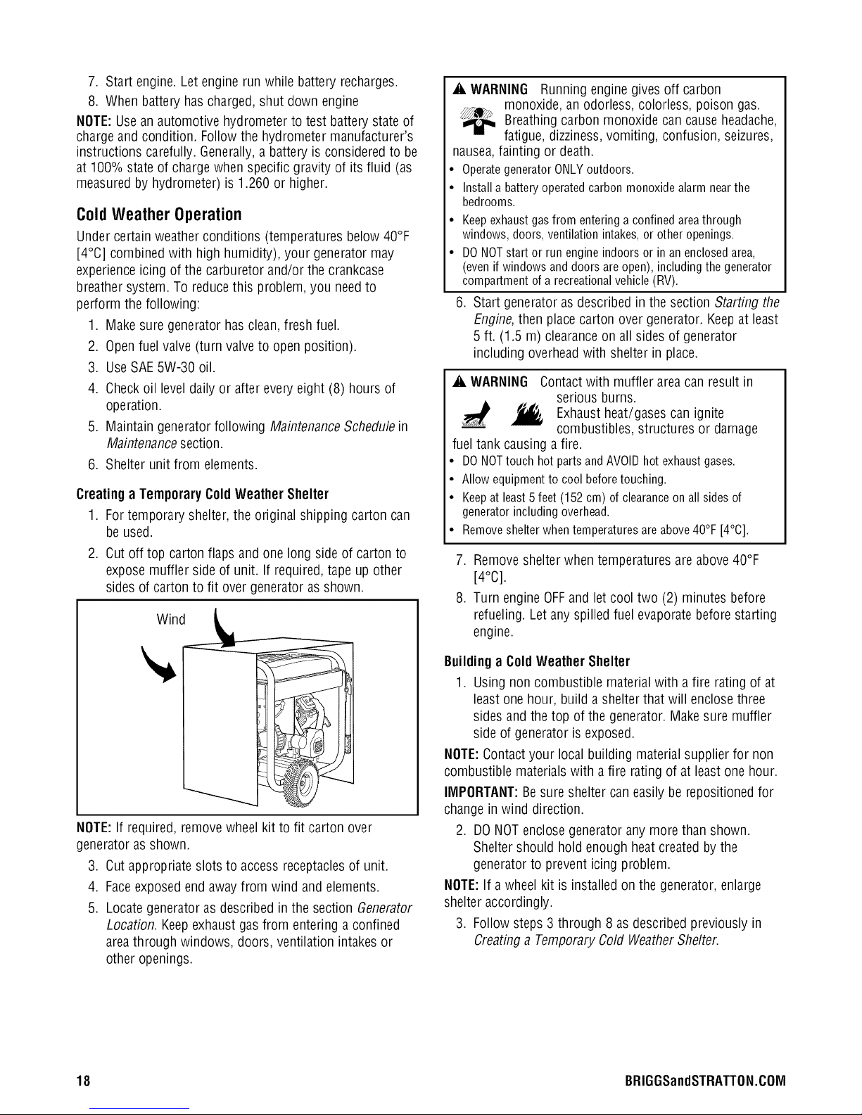
Creatinga TemporaryColdWeather Shelter
1. For temporary shelter, the original shipping carton can
be used.
2. Cut off top carton flaps and one long sideof carton to
expose muffler side of unit. If required,tape up other
sides of carton to fit over generator as shown.
Wind
_i, WARNING Runningengine gives off carbon
monoxide, an odorless, colorless, poison gas.
Breathingcarbon monoxide cancause headache,
fatigue, dizziness,vomiting, confusion, seizures,
nausea,fainting or death.
• OperategeneratorONLYoutdoors.
• Installa batteryoperatedcarbonmonoxidealarmnearthe
bedrooms.
• Keepexhaustgasfromenteringaconfinedareathrough
windows,doors,ventilationintakes,or otheropenings.
• DONOTstartor run engineindoorsor in anenclosedarea,
(evenifwindowsanddoorsareopen),includingthegenerator
compartmentofa recreationalvehicle(RV).
6. Start generatoras described in the section Starting the
Engine,then placecarton over generator. Keepat least
5 ft. (1.5 m) clearanceon all sides of generator
including overheadwith shelter in place.
_i, WARNING Contactwith muffler area can result in
serious burns.
Exhaustheat/gases can ignite
combustibles, structures or damage
fuel tank causinga fire.
• DONOTtouchhotpartsandAVOIDhotexhaustgases.
• Allowequipmentto coolbeforetouching.
• Keepatleast5feet(152cm)of clearanceonall sidesof
generatorincludingoverhead.
• Removeshelterwhentemperaturesareabove40°F[4°C].
7. Remove shelter when temperatures areabove40°F
[4°C].
8. Turn engine OFFand let cool two (2) minutes before
refueling. Let anyspilled fuel evaporatebefore starting
engine.
NOTE:If required, removewheel kit to fit carton over
generator asshown.
3. Cut appropriate slots to access receptaclesof unit.
4. Faceexposedend away from wind and elements.
5. Locate generatoras described in the section Generator
Location. Keepexhaust gasfrom entering a confined
areathrough windows, doors, ventilation intakesor
other openings.
Buildinga ColdWeather Shelter
1. Using non combustible materialwith a fire rating of at
least one hour, build a shelter that will enclosethree
sides and the top of the generator. Makesure muffler
side of generator is exposed.
NOTE:Contactyour local building material supplier for non
combustible materials with a fire rating of at least one hour.
IMIPORTANT:Besure shelter caneasily be repositioned for
changein wind direction.
2. DO NOTenclosegeneratorany more than shown.
Sheltershould hold enoughheat createdby the
generatorto prevent icing problem.
NOTE:If a wheel kit is installed on the generator, enlarge
shelter accordingly.
3. Follow steps 3 through 8 asdescribed previously in
Creatinga TemporaryCold WeatherShelter.
18 BRIGGSandSTRATTON.C01Vl
Page 19

Don't Overload Generator
Capacity
You must make sureyour generator can supply enough
rated (running) and surge (starting) watts for the items you
will power at the sametime. Follow these simple steps:
1. Selectthe itemsyou will power at the same time.
2. Total the rated(running) watts of theseitems. This is
the amount of power your generator must produce to
keepyour items running. Seethe table on the right.
3. Estimatehow many surge (starting) watts you will need.
Surge wattage is the short burst of power neededto
start electric motor-driven tools or appliancessuch asa
circular sawor refrigerator. Becausenot all motors start
atthe sametime, total surgewatts can be estimatedby
adding only the item(s) with the highestadditionalsurge
watts to the total rated watts from step 2.
Example:
Running(Rated)
Toolor Appliance
WaterWell Pump
Refrigerator
FurnaceFan
Television
Light (75 Watts)
Total Rated(Running) Watts
HighestAdditional Surge Watts
Total Generator Output Required
Power Management
To prolong the life of your generatorand attacheddevices, it
is important to take carewhen adding electrical loadsto your
generator. There should be nothing connectedto the
generator outlets before starting its engine.Thecorrect and
safe way to managegeneratorpower isto sequentiallyadd
loads asfollows:
1. With nothing connectedto the generator,start the
engine as described in this manual.
2. Plug in andturn on the first load, preferablythe largest
load you have.
3. Permit the generatoroutput to stabilize (engine runs
smoothly and attacheddeviceoperates properly).
4. Plug in andturn on the next load.
5. Again, permit the generator to stabilize.
6. Repeatsteps 4 and5 for eachadditional load.
Watts
1200
700
800
500
75
3275 Total
RunningWatts
AdditionalStarting
(Surge) Watts
21O0
2200
2350
2350 Highest
Starting Watts
= 3275
= 2350
= 5625
WattageReferenceGuide
Running* Additional
Tool orAppliance (Rated) Starting
Watts (Surge)
Watts
Essentials
Light Bulb - 75 watt 75 --
FurnaceFanBlower- 1/2 HP 800 2350
Sump Pump- 1/3 HP 800 1300
Refrigerator/Freezer 700 2200
Water Well Pump - 1/2 HP 1000 2100
Heating/Cooling
Window AC- 10,000 BTU 1200 3600
Humidifier- 13 Gal 175 --
CentralAC- 24,000 BTU 3800 11400
Kitchen
Microwave Oven- 1000 Watt 1000 --
CoffeeMaker 1000 --
Electric Stove - 8" Element 2100 --
Toaster 850 --
Family Room
DVD/CDPlayer 100 --
VCR 100 --
Stereo Receiver 450 --
Color Television- 27 in 500 --
PersonalComputer w/17 in 800 --
monitor
Other
Security System 500 --
AM/FM Clock Radio 100 --
GarageDoor Opener- 1/2 HP 875 2350
ElectricWater Heater 4700 11700
DIY/JohSite
Quartz HalogenWork Light 1000 --
Airless Sprayer- 1/3 HP 600 1200
Reciprocating Saw 960 --
Electric Drill - 1/2 HP, 5.4 Amps 600 900
Circular Saw - 7-1/4 in 1400 2300
Miter Saw- 10 in 1800 1800
TablePlaner - 6 in 1800 1800
TableSaw/RadialArm Saw - 10 in 2000 2000
Air Compressor- 1 HP 1600 4500
NEVERadd more loads than the generatorcapacity.Take
special care to consider surge loads in generator capacity,as
described above.
* Wattageslisted are approximate only. Checktool or
appliancefor actual wattage.
19
Page 20
Maintenance
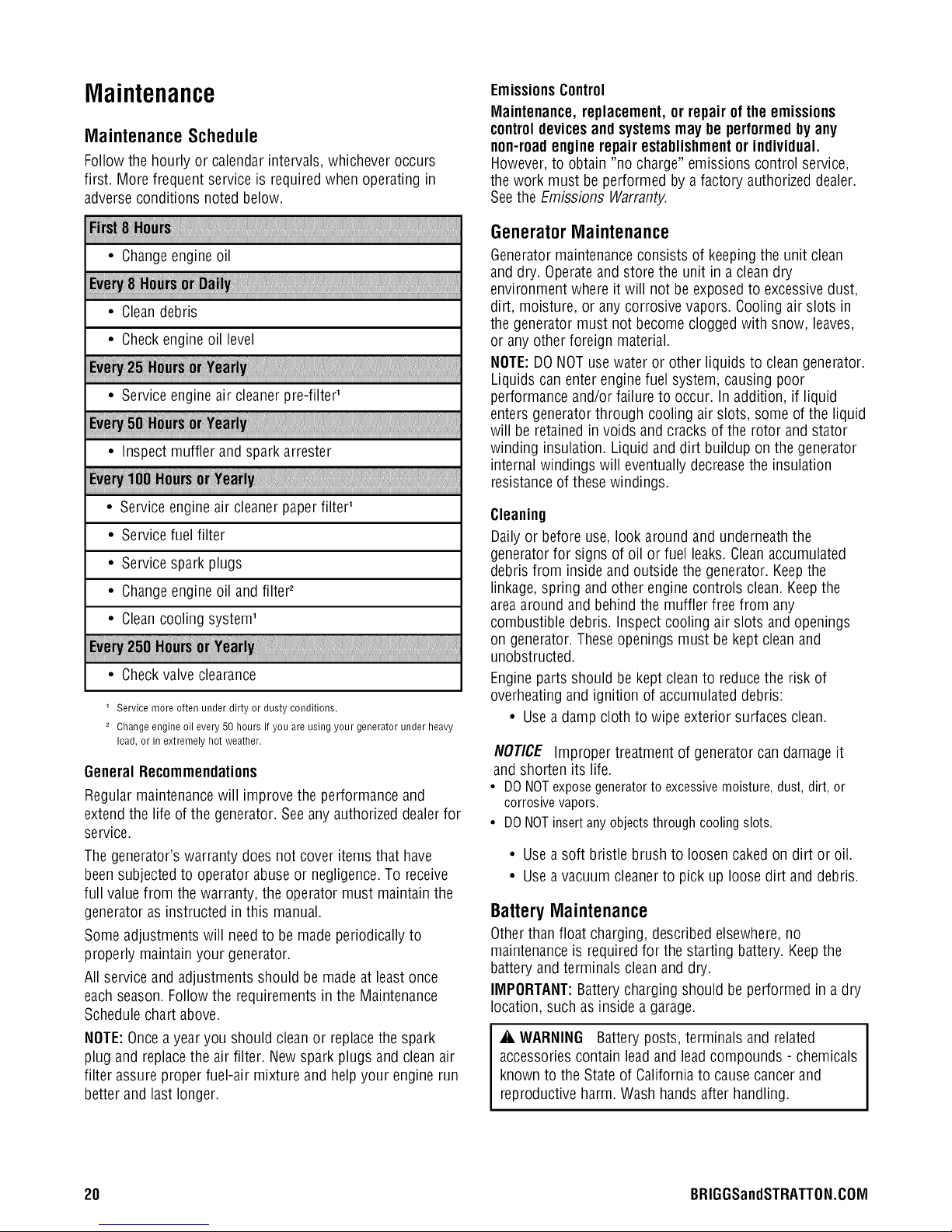
MaintenanceSchedule
Follow the hourly or calendarintervals, whichever occurs
first. More frequent serviceis required when operating in
adverseconditions noted below.
EmissionsControl
Maintenance, replacement, or repair of the emissions
controldevicesand systemsmay be performedby any
non-roadengine repair establishmentor individual.
However,to obtain "no charge" emissions control service,
the work must be performed by a factory authorized dealer.
Seethe Emissions Warranty.
!
• Changeengine oil
• Cleandebris
• Checkengineoil level
• Serviceengineair cleanerpre-filter'
• Inspect muffler and spark arrester
• Serviceengine air cleanerpaper filter'
• Servicefuel filter
• Servicespark plugs
• Changeengine oil and filter2
• Cleancooling system'
• Checkvalve clearance
1 Service more often under dirty or dusty conditions.
2 Change engine oil every 50 hours if you are using your generator under heavy
load, or in extremely hot weather.
GeneralRecommendations
Regular maintenancewill improve the performance and
extend the life of the generator. Seeany authorizeddealer for
service.
Thegenerator's warranty doesnot cover items that have
been subjectedto operator abuse or negligence.To receive
full valuefrom the warranty, the operator must maintain the
generator asinstructed in this manual.
Someadjustments will needto be made periodicallyto
properly maintain your generator.
All serviceand adjustments should be made at least once
eachseason.Followthe requirements in the Maintenance
Schedulechart above.
NOTE:Oncea year you should clean or replacethe spark
plug and replacethe air filter. New spark plugs and cleanair
filter assure proper fuel-air mixture and help your engine run
better and last longer.
GeneratorMaintenance
Generatormaintenanceconsists of keepingthe unit clean
and dry. Operateand store the unit in a clean dry
environment where it will not be exposedto excessivedust,
dirt, moisture, or any corrosive vapors. Coolingair slots in
the generator must not become cloggedwith snow, leaves,
or any other foreign material.
NOTE:DO NOTusewater or other liquids to clean generator.
Liquids canenter enginefuel system, causing poor
performance and/or failure to occur. In addition, if liquid
enters generator through cooling air slots, some of the liquid
will be retainedin voids and cracks of the rotor and stator
winding insulation. Liquid and dirt buildup on the generator
internal windings will eventuallydecreasethe insulation
resistanceof these windings.
Cleaning
Dailyor before use, look around and underneaththe
generatorfor signs of oil or fuel leaks. Cleanaccumulated
debris from inside and outside the generator. Keepthe
linkage, spring and other engine controls clean. Keepthe
areaaround andbehind the muffler free from any
combustible debris. Inspect cooling air slots and openings
on generator. Theseopenings must bekept cleanand
unobstructed.
Engine parts should be keptcleanto reduce the risk of
overheating and ignition of accumulateddebris:
• Usea damp cloth to wipe exterior surfaces clean.
NOTICE Improper treatment of generator can damage it
and shorten its life.
• DO NOTexposegenerator to excessivemoisture, dust, dirt, or
corrosive vapors.
• DONOTinsert any objectsthrough cooling slots.
• Usea soft bristle brush to loosen cakedon dirt or oil.
• Usea vacuum cleanerto pick uploose dirt and debris.
BatteryMaintenance
Otherthan float charging, described elsewhere,no
maintenanceis requiredfor the starting battery. Keepthe
battery and terminals cleanand dry.
IMPORTANT:Batterycharging should be performed in a dry
location, such as inside a garage.
A. WARNING Battery posts, terminals and related
accessoriescontain leadand leadcompounds - chemicals
known to the State of Californiato cause cancerand
reproductiveharm. Wash handsafter handling.
20 BRIGGSandSTRATTON.COIVl
Page 21
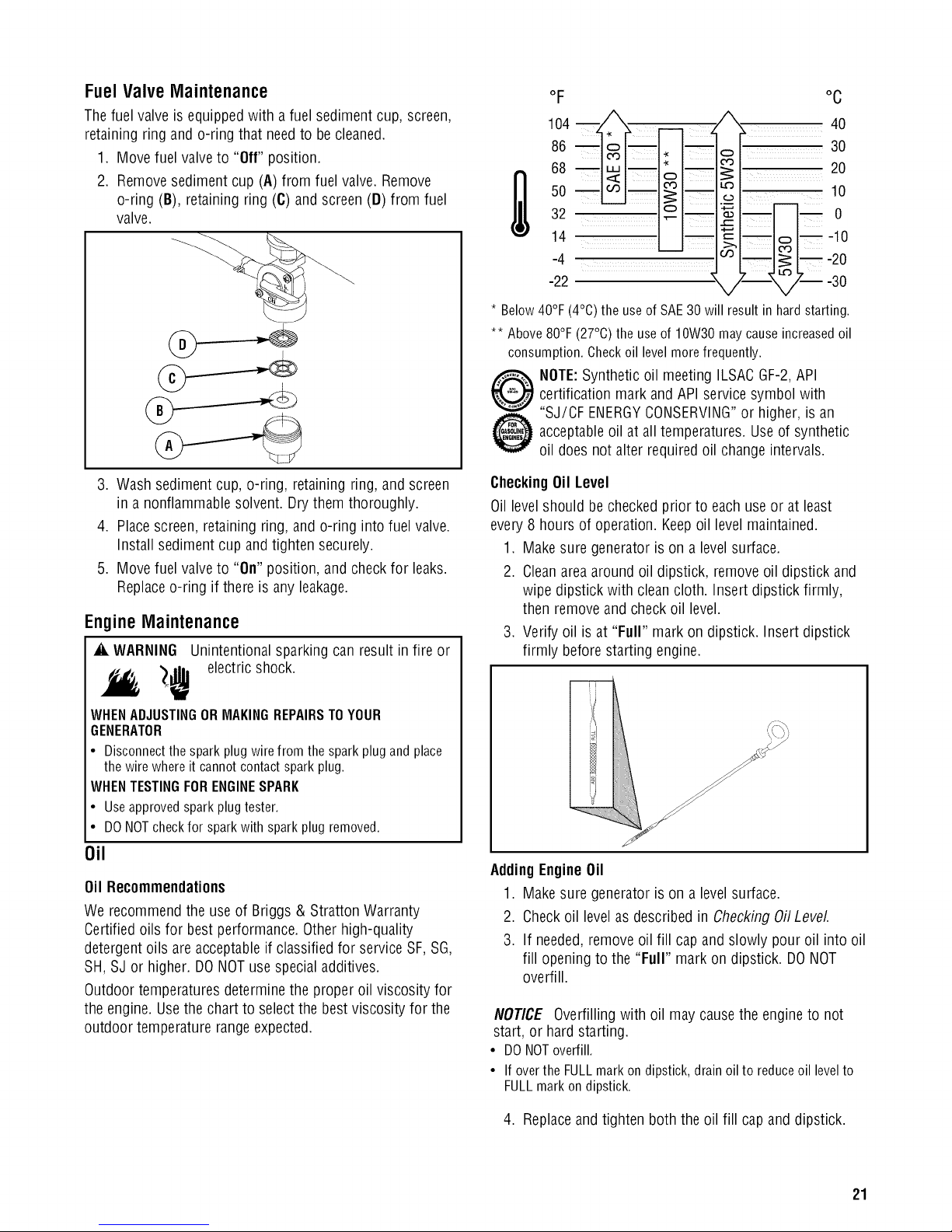
FuelValve Maintenance
Thefuel valve is equippedwith a fuel sediment cup, screen,
retaining ring and o-ring that needto becleaned.
1. Move fuel valve to "Off" position.
2. Remove sediment cup (A) from fuel valve. Remove
o-ring (B), retaining ring (C) and screen (D) from fuel
valve.
oF oc
68 _mo >_20
104 n _, __ , !l_'X_ 40
86 _om__ _,_ o__ 30
so 10
32 o ._m -- 0
-2214-4 -- , l--___' -30-20-10
3. Wash sediment cup, o-ring, retaining ring, and screen
in anonflammable solvent. Dry them thoroughly.
4. Place screen, retaining ring, and o-ring into fuel valve.
Install sedimentcup andtighten securely.
5. Move fuel valve to "On" position, and checkfor leaks.
Replaceo-ring if there is any leakage.
EngineMaintenance
_i, WARNING Unintentionalsparking can result infire or
_ electric shock.
WHENADJUSTINGORMAKINGREPAIRSTOYOUR
GENERATOR
• Disconnectthesparkplugwirefromthesparkplugandplace
thewirewhereit cannotcontactsparkplug.
WHENTESTINGFORENGINESPARK
• Useapprovedsparkplugtester.
• DONOTcheckfor sparkwith sparkplugremoved.
Oil
Oil Recommendations
We recommendthe useof Briggs & Stratton Warranty
Certified oils for best performance. Other high-quality
detergent oils are acceptableif classified for serviceSF, SG,
SH, SJ or higher. DONOTuse specialadditives.
Outdoor temperatures determine the proper oil viscosity for
the engine. Usethe chart to select the bestviscosity for the
outdoor temperature rangeexpected.
* Below 40°F
** Above 80°F (27°C) the useof 10W30 may cause increased oil
consumption. Check oil levelmorefrequently.
CheckingOil Level
Oil levelshould be checked prior to each use or at least
every 8 hours of operation. Keepoil levelmaintained.
1. Make sure generatoris on a level surface.
2. Cleanarea aroundoil dipstick, remove oil dipstick and
3. Verify oil is at "Full" mark on dipstick. Insert dipstick
AddingEngineOil
1. Make sure generatoris on a level surface.
2. Check oil levelas described in Checking OilLevel
3. If needed,remove oil fill cap andslowly pour oil into oil
NOTICE Overfilling with oil may causethe engine to not
start, or hard starting.
• DONOToverfill.
• If over the FULLmark on dipstick, drain oil to reduce oil levelto
FULLmark on dipstick.
(4°C)theuseof SAE30will resultinhardstarting.
certification mark and API service symbol with
NOTE:Synthetic oil meeting ILSACGF-2,API
"SJ/CF ENERGYCONSERVING"or higher, is an
acceptableoil at all temperatures. Useof synthetic
oil does not alter required oil change intervals.
wipe dipstick with clean cloth. Insert dipstick firmly,
then remove and check oil level.
firmly before starting engine.
fill opening to the "Full" mark on dipstick. DONOT
overfill.
4. Replaceandtighten both the oil fill cap and dipstick.
21
Page 22
ChangingEngine Oil and Filter
If you are usingyour generator under heavyload, or in
extremely hot weather, changethe oil more often.
_i, CAUTION Avoid prolonged or repeated skin contact
with used motor oil.
• Used motor oil has beenshown to cause skin cancer in certain
laboratory animals.
• Thoroughly wash exposed areaswith soap and water.
KEEPOUTOFREACHOFCHILDREN.DON'T
POLLUTE.CONSERVERESOURCES.RETURN
USEDOILTOCOLLECTIONCENTERS.
Changethe oil while the engine is still warm from
running,as follows:
1. Make sure unit is on a levelsurface.
2. Disconnect the spark plug wiresfrom the spark plug
and place the wire where it cannot contact spark plugs.
3. Cleanarea around oil drain plug.The oil drain plug is
located at base of engine.
4. Remove oil drain plug and oil fill cap and drain oil
completely into asuitable container.
5. Reinstall oil drain plug andtighten securely.
6. Place a suitable container beneathoil filter and turn
filter counterclockwiseto remove.
7. Lightly coat gasketof a new filter with fresh engineoil.
Turn new filter clockwise until gasketcontacts filter
adapter,then tighten an additional 3/4 turn.
8. Remove oil dipstick.
9. Slowly pour 32 oz. (1 liter) of recommendedoil into oil
fill opening.
10. Start and run enginefor 30 seconds. Shut engine off
and wait 30 secondsfor oil to settle.
11. Add more oil to "Full" mark on dipstick. Wipe dipstick
cleaneachtime oil level is checked. DONOToverfill.
NOTE:Engineholds approximately 48 oz. (1.4 liters) when
changing oil andfilter.
12. Reinstall oil fill cap and oil dipstick. Tighten oil fill cap
securely.
13. Wipe up any spilled oil.
14. Reconnectspark plug wires to spark plugs.
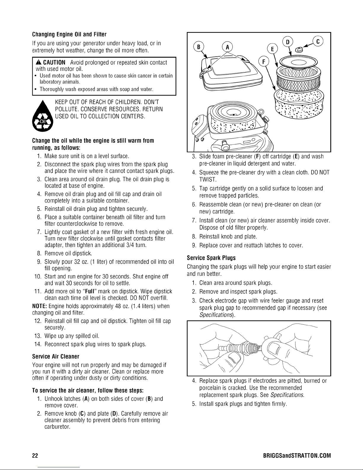
3. Slide foam pre-cleaner(F) off cartridge (E) and wash
pre-cleanerin liquid detergentand water.
4. Squeezethe pre-cleanerdry with a clean cloth. DO NOT
TWIST.
5. Tap cartridge gently ona solid surface to loosen and
remove trapped particles.
6. Reassembleclean (or new) pre-cleaneron clean (or
new) cartridge.
7. Install clean (or new) air cleanerassembly inside cover.
Disposeof old filter properly.
8. Reinstall knob andplate.
9. Replacecover and reattachlatchesto cover.
Service Spark Plugs
Changingthe spark plugs will help your engineto start easier
and run better.
1. Cleanarea aroundspark plugs.
2. Remove and inspect spark plugs.
3. Check electrode gapwith wire feeler gaugeand reset
spark pluggap to recommended gap if necessary(see
Specifications).
Service Air Cleaner
Your enginewill not run properly and may be damaged if
you run it with a dirty air cleaner.Cleanor replacemore
often if operating under dusty or dirty conditions.
To servicetheair cleaner, followthese steps:
1. Unhook latches (A) on both sidesof cover (B) and
removecover.
2. Remove knob (C) and plate(D). Carefully removeair
cleanerassembly to prevent debris from entering
carburetor.
22 BRIGGSandSTRATTON.COIVl
4. Replacespark plugs if electrodes arepitted, burned or
porcelain is cracked. Use the recommended
replacementspark plugs. See Specifications.
5. Install spark plugs and tighten firmly.
Page 23

Inspect Muffler and SparkArrester
Theengine exhaustmuffler hasa spark arresterscreen.
Inspect the muffler for cracks, corrosion, or other damage.
Removethe spark arrester and inspect for damageor carbon
blockage. If replacementparts are required,make sure to
use only original equipment replacement parts.
_i, WARNING Contact with muffler area can result in
serious burns.
Exhaust heat/gases can ignite
combustibles, structures or damage
fuel tank causing a fire.
• DO NOTtouch hot parts and AVOID hot exhaust gases.
• Allow equipment to cool beforetouching.
• Keepat least5 feet (152 cm) of clearanceon all sidesof
generator including overhead.
• It is a violation of California Public Resource Code, Section
4442, to use or operatethe engineon anyforest-covered,
brush-covered, or grass-covered land unlessthe exhaust
system is equipped with a spark arrester, as defined in Section
4442, maintained in effective working order. Other states or
federal jurisdictions may havesimilar laws.
Contactthe original equipment manufacturer, retailer, or dealer
to obtain a spark arrester designed for the exhaust system
installed on this engine.
• Replacement parts must bethe sameand installed in the same
position asthe original parts.
Cleanand inspectthesparkarrester as follows:
1. Remove four screws that attach the spark arrester
screen.
CleanCoolingSystem
Overtime debris may accumulatein cylinder cooling fins and
cannot be observedwithout partial engine disassembly. For
this reason,we recommend you have an authorized service
dealer clean the cooling system per recommendedintervals
(see MaintenanceSchedule in the Maintenancesection).
Equallyimportant is to keep top of enginefree from debris.
Also see Cleaning.
CheckValve Clearance
Regularvalve clearancecheck andadjustment will improve
performance and extend engine life. This procedure cannot
be done without partial enginedisassemblyand the useof
special tools. For this reason we recommend that you have
an authorized Service Dealercheck and adjust valve
clearanceat recommended intervals (seeMaintenance
Schedulein the Maintenancesection).
2. Inspect screenand replaceif torn, perforated or
otherwise damaged. DO NOTUSEa defective screen. If
screen is not damaged,clean it with commercial
solvent.
3. Reattachthe screen with four screws.
CarburetorAdjustment
Thecarburetor on this engineis low emission. It is equipped
with a non-adjustable idle mixture valve.Top speedhas been
set at the factory. If adjustment is required,seean
authorized service dealer.
_i, CAUTION Excessively high operating speeds increase
risk of injury and damage to generator.
Excessively low speeds impose a heavy load.
• DO NOTtamper with governedspeed. Generatorsupplies
correct rated frequency andvoltage when running at governed
speed.
• DO NOTmodify generator in any way.
23
Page 24
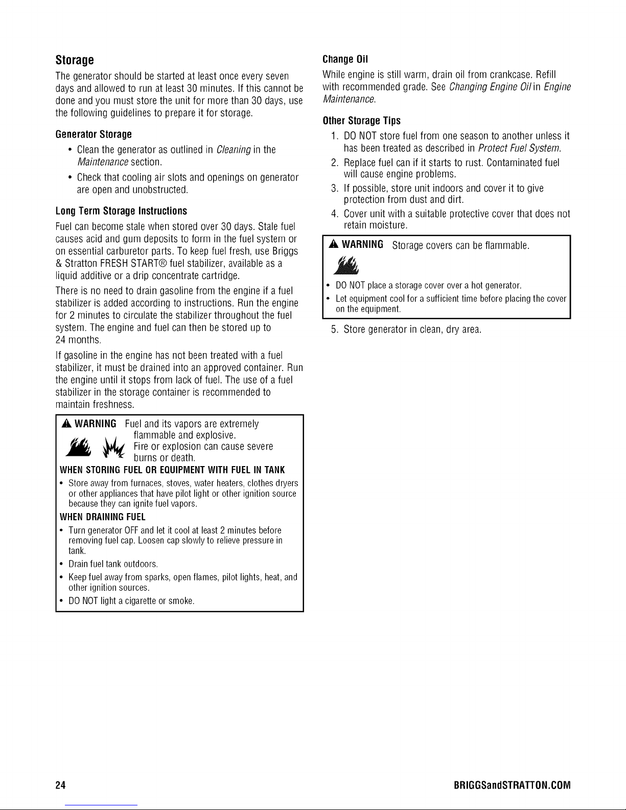
Storage
Thegenerator should be started at least once everyseven
days and allowed to run at least 30 minutes. If this cannot be
done and you must store the unit for more than 30 days,use
the following guidelinesto prepare it for storage.
GeneratorStorage
• Cleanthe generator as outlined in Cleaningin the
Maintenancesection.
• Checkthat cooling air slots and openingson generator
are open and unobstructed.
LongTerm StorageInstructions
Fuelcan becomestale when stored over 30 days.Stale fuel
causesacid and gum deposits to form in the fuel system or
on essential carburetor parts. To keep fuel fresh, use Briggs
& Stratton FRESHSTART® fuel stabilizer, availableasa
liquid additive or a drip concentrate cartridge.
Thereis no needto drain gasolinefrom the engineif a fuel
stabilizer is added according to instructions. Run the engine
for 2 minutes to circulate the stabilizer throughout the fuel
system. The engine andfuel canthen be stored up to
24 months.
If gasoline in the engine hasnot beentreated with a fuel
stabilizer, it must be drained into an approvedcontainer. Run
the engine until it stops from lack of fuel. The useof a fuel
stabilizer in the storage container is recommendedto
maintain freshness.
ChangeOil
While engine is still warm, drain oil from crankcase. Refill
with recommendedgrade.SeeChangingEngine Oilin Engine
Maintenance.
OtherStorageTips
1. DO NOTstorefuel from one seasonto another unless it
has beentreated as described in Protect Fuel System.
2. Replacefuel can if it starts to rust. Contaminatedfuel
will cause engine problems.
3. If possible, store unit indoors and cover it to give
protection from dust and dirt.
4. Cover unit with a suitable protective cover that does not
retain moisture.
_i, WARNING Storagecovers can be flammable.
• DO NOTplace a storage cover over a hot generator.
• Let equipment coolfor a sufficient time before placingthe cover
on the equipment.
5. Store generator inclean, dry area.
_i, WARNING Fueland its vapors areextremely
flammable and explosive.
_ J
_, _ Fireor explosion can causesevere
burns or death.
WHENSTORINGFUELOREQUIPMENTWITHFUELINTANK
• Store away from furnaces, stoves, water heaters,clothes dryers
or other appliances that have pilot light or other ignition source
becausethey can ignite fuel vapors.
WHENDRAININGFUEL
• Turn generator OFFand let it cool at least 2 minutes before
removing fuel cap. Loosen cap slowly to relieve pressure in
tank.
• Drain fuel tank outdoors.
• Keepfuel awayfrom sparks, open flames, pilot lights, heat,and
other ignition sources.
• DO NOTlight acigarette or smoke.
24 BRIGGSandSTRATTON.COM
Page 25
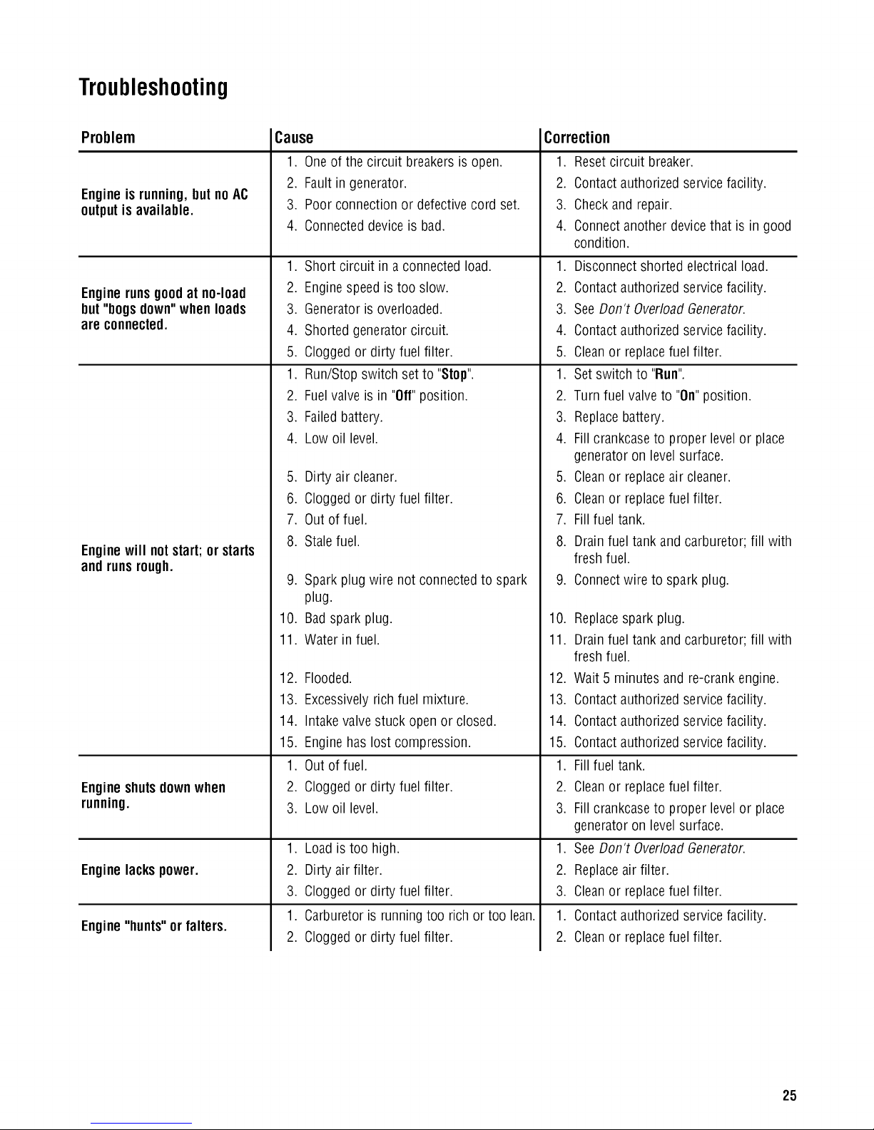
Troubleshooting
Problem
Engineisrunning,but noAC
outputis available.
Enginerunsgoodat no-load
but"bogs down"whenloads
are connected.
Enginewill notstart; or starts
and runsrough.
Engineshutsdownwhen
running.
Enginelackspower.
Engine"hunts" or falters.
Cause
1. Oneof the circuit breakers is open.
2. Fault in generator.
3. Poor connection or defective cord set.
4. Connected deviceis bad.
,
Short circuit in a connected load. 1.
2.
Enginespeed is too slow. 2.
3.
Generatoris overloaded. 3.
4.
Shorted generator circuit. 4.
5.
Cloggedor dirty fuel filter. 5.
1. Run/Stop switch set to "Stop".
2. Fuel valve is in "Off"position.
3. Failed battery.
4. Low oil level.
5. Dirty air cleaner.
6. Clogged or dirty fuel filter.
7. Out of fuel.
8. Stale fuel.
9. Spark plug wire not connectedto spark
plug.
10. Badsparkplug.
11. Water in fuel.
12. Flooded.
13.
Excessivelyrich fuel mixture. 13.
14.
Intakevalvestuck openor closed. 14.
15.
Engine has lost compression. 15.
1.
Out of fuel. 1.
2.
Cloggedor dirty fuel filter. 2.
3.
Low oil level. 3.
1. Loadis too high.
2. Dirty air filter.
3. Clogged or dirty fuel filter.
1. Carburetoris runningtoo rich or too lean.
2. Clogged or dirty fuel filter.
Correction
1. Reset circuit breaker.
2. Contactauthorizedservice facility.
3. Checkand repair.
4. Connect anotherdevice that is in good
condition.
Disconnectshorted electrical load.
Contactauthorized service facility.
SeeDon't OverloadGenerator.
Contactauthorized service facility.
Cleanor replacefuel filter.
1. Set switch to "Run".
2. Turn fuel valveto "On"position.
3. Replacebattery.
4. Fill crankcaseto proper levelor place
generatoron level surface.
5. Cleanor replaceair cleaner.
6. Cleanor replacefuel filter.
7. Fill fuel tank.
8. Drain fuel tank and carburetor; fill with
fresh fuel.
9. Connectwire to spark plug.
10. Replacesparkplug.
11. Drain fuel tank and carburetor; fill with
fresh fuel.
12. Wait 5 minutes and re-crank engine.
Contactauthorized service facility.
Contactauthorized service facility.
Contactauthorized service facility.
Fillfuel tank.
Cleanor replacefuel filter.
Fillcrankcaseto proper levelor place
generatoron level surface.
,
SeeDon't OverloadGenerator.
2.
Replaceair filter.
3.
Cleanor replacefuel filter.
1.
Contactauthorized service facility.
2.
Cleanor replacefuel filter.
25
Page 26
iA
600V
I3A i3
FLOAT SWI
JACK START/RUN
CONTACTOR
13 _ 13B
IA I
iOVDC
BATTERY
CONTACTOR STARTER
FOB
iO A_P
13C
ETN
IOV DC
HOURNETER
13A _ 55
BC
IOVDC
iOA
COB
13A _ i5 55
IDLE
CONTROL 5_ 155
G
4 I56
THROTTLE
i CONTROL
0 S_ICB NOTOR
2
CBB
30A
2P
i3
201
®
CT
22 o 22 VOLTAGE
REGULATOR
BL 2 6 TE
i FIELD
za _ 4
POWER
iFOTEEO_
DPI
iaov
20A
s B llC a_
V iaOV
WHITE 30A lib
lib CB4_A
WHI1
lib x
120/240V
T WHII BBOV
50A
xl
155
156
I' S' D' 1£A_
#B ENG,
IGNITION
1OA
#i ENG,
IGNITION
44C C.C_B344c_ L
44A
RUN/STOP
18 _ O
T_R
1R R
B-BRASS SCREW
S-SILVER SCREW
OR-GREEN SCREW
=;
r_
l--
r_
Page 27

156 i
155
44 _ II
SN
i55
156
THROTTLE
i CONTROL
MOTOR
3_ 0
2
2 i 18
sWi 0 i8
1_55 _
443 44B
llc 22 i (
ss! I ' --
L
TLi
}
33
ETM
13A
o o o
IIA
CBl
........
--3-......_--_-II
WHITE I
I@I
TB
ii ii
23 _4HI_ 22 22
33 0 33
0
II
n
REGULATOR
BLUE BOARD BLUE
(6)
HOTEl POSITIVE BRUSH is CLOSEST TO BEARING
".4
Page 28
Warranties
California,U.S. EPA,andBriggs& Stratton
CorporationEmissionsControlWarranty
Statement
YourWarranty RightsAndObligations
The CaliforniaAir ResourcesBoard,U.S. EPA,and Briggs &
Stratton (B&S) arepleasedto explainthe emissions control
system warranty on your Model Year 2008 andlater
engine/equipment. In California, new small off-road engines
must be designed, built, andequipped to meet the State's
stringent anti-smog standards. B&S must warrant the
emissions control system on your engine/equipmentfor the
periods of time listed below provided there has been no
abuse, neglect,or improper maintenanceof your small off-
road engine.
Your emissions control system may include parts such as
the carburetor or fuel injection system, fuel tank, ignition
system, andcatalytic converter. Also included may behoses,
belts, connectors, sensors, and other emissions-related
assemblies.Whereawarrantable condition exists, B&Swill
repair your engine/equipment at no cost to you including
diagnosis, parts, and labor.
Manufacturer's WarrantyCoverage:
Small off-road engines arewarranted for two years. If any
emissions-related part on your engine/equipment is
defective,the part will berepaired or replacedby B&S.
Owner's WarrantyResponsibilities:
• As the small engine/equipment owner,you are
responsiblefor the performance of the required
maintenancelisted in your owner's manual. B&S
recommendsthat you retainall receipts covering
maintenanceonyour engine/equipment, but B&S
cannot deny warranty solelyfor the lack of receiptsor
your failure to ensure the performance of all scheduled
maintenance.
• As the engine/equipmentowner, you should however
be aware that B&S may deny you warranty coverageif
your engine/equipmentor apart hasfailed due to
abuse, neglect,improper maintenance,or unapproved
modifications.
• Youare responsiblefor presentingyour
engine/equipmentto a B&Sdistribution center,
servicing dealer,or other equivalententity, as
applicable, as soon as a problem exists. Thewarranty
repairsshould be completed ina reasonableamount of
time, not to exceed30 days. If you haveany questions
regardingyour warranty rights and responsibilities, you
should contact B&Sat (414) 259-5262.
Briggs& StrattonEmissionsControlWarrantyProvisions
Thefollowing are specific provisions relativeto your
Emissions Control Warranty Coverage.It is inaddition to the
B&S enginewarranty for non-regulated enginesfound in the
Operator's Manual.
1. Warranted Emissions Parts
Coverageunder this warranty extends only to the parts
listed below (the emissions control systems parts) to
the extentthese partswere present on the engine
purchased.
a. FuelMetering System
• Cold start enrichment system (soft choke)
• Carburetorand internal parts
• Fuelpump
• Fuelline, fuel line fittings, clamps
• Fueltank, capand tether
• Carboncanister
b. Air Induction System
• Air cleaner
• Intake manifold
• Purgeand vent line
C,
Ignition System
• Spark plug(s)
• Magnetoignition system
d,
CatalystSystem
• Catalyticconverter
• Exhaustmanifold
• Air injection system or pulse valve
e. MiscellaneousItems Usedin Above Systems
• Vacuum,temperature, position, time sensitive
valvesand switches
• Connectorsand assemblies
,
Length of Coverage
For a period of two years from date of original
purchase, B&S warrants to the original purchaserand
eachsubsequent purchaserthat the engine is designed,
built, and equippedso asto conform with all applicable
regulations adopted by the Air Resources Board;that it
is free from defects in material and workmanship that
could cause the failure of a warranted part; andthat it
is identical in all material respects to the engine
described in the manufacturer's application for
certification. The warranty period beginson the datethe
engine is originally purchased.
28 BRIGGSandSTRATTON.COM
Page 29
Thewarranty on emissions-related parts is asfollows:
• Anywarranted part that is not scheduledfor
replacementas required maintenancein the owner's
manual supplied, is warranted for the warranty period
stated above. If any such part fails during the period of
warranty coverage,the part will berepairedor replaced
by B&S at no charge to the owner. Any such part
repaired or replacedunder the warranty will be
warranted for the remaining warranty period.
• Anywarranted part that is scheduled only for regular
inspection in the owner's manual supplied, is warranted
for the warranty period statedabove. Any such part
repaired or replacedunder warranty will be warranted
for the remaining warranty period.
• Anywarranted partthat is scheduledfor replacementas
required maintenancein the owner's manualsupplied, is
warrantedfor the period of time prior to thefirst
scheduledreplacementpointfor that part.If the part fails
prior to the first scheduled replacement,the part will be
repairedor replacedby B&S at no chargeto the owner.
Anysuch part repairedor replacedunderwarrantywill
be warrantedfor the remainderof the period prior to the
first scheduledreplacementpointfor the part.
• Addon or modified parts that are not exempted bythe
Air ResourcesBoard may not be used.The use of any
non exempted add on or modified parts by the owner
will be grounds for disallowing a warranty claim. The
manufacturer will not be liable to warrant failures of
warranted parts caused by the use of a non exempted
add on or modified part.
3. ConsequentialCoverage
Coverageshall extend to the failure of anyengine
components causedby the failure of anywarranted
emissions parts.
4. Claims and CoverageExclusions
Warranty claims shall be filed according to the
provisions of the B&S enginewarranty policy. Warranty
coveragedoes not apply to failuresof emissions parts
that are not original equipment B&S partsor to parts
that fail due to abuse, neglect,or improper maintenance
as set forth in the B&S engine warranty policy. B&Sis
not liable for warranty coverageof failures of emissions
parts causedby the use of add-on or modified parts.
LookFor RelevantEmissionsDurabilityPeriod andAir
IndexInformationOnYour EngineEmissionsLabel
Enginesthat are certified to meetthe CaliforniaAir
ResourcesBoard (CARD)Emissions Standardmust display
information regardingthe Emissions Durability Period and
the Air Index. Briggs & Stratton makesthis information
availableto the consumer on our emissions labels. The
engine emissions labelwill indicatecertification information.
TheEmissionsDurabilityPerioddescribesthe number of
hours of actual running time for which the engine is certified
to be emissions compliant, assuming proper maintenancein
accordancewith the Operating & Maintenance Instructions.
Thefollowing categories are used:
Moderate:
Engine is certified to be emissions compliant for 125 hours
of actual enginerunning time.
Intermediate:
Engine is certified to be emissions compliant for 250 hours
of actual enginerunning time.
Extended:
Engine is certified to be emissions compliant for 500 hours
of actual enginerunning time.
Forexample,atypical walk-behind lawn mower is used 20 to
25 hours peryear. Therefore,the Emissions Durability
Period of an engine with an intermediate rating would
equateto 10 to 12 years. Briggs & Stratton engines are
certified to meet the United States EnvironmentalProtection
Agency (USEPA)Phase2 emissions standards. For Phase2
certified engines, the Emissions CompliancePeriod referred
to on the Emissions Compliance label indicatesthe number
of operating hours for which the engine has beenshown to
meet Federalemissions requirements.
Forengines less than 225 cc displacement.
CategoryC= 125 hours
CategoryB = 250 hours
CategoryA = 500 hours
Forengines of 225 cc or more displacement.
CategoryC= 250 hours
CategoryB = 500 hours
CategoryA = 1000 hours
29
Page 30

Effective December 1,2005 replaces all undated Warranties and all Warranties dated before December 1, 2005
LIMITED WARRANTY
Briggs& StrattonPowerProductsGroup,LLCwill repairorreplace,freeofcharge,anypart(s)oftheportablegeneratorthat isdefectivein materialor
workmanshipor both.Transportationchargesonproductsubmittedfor repairor replacementunderthiswarrantymustbebornebypurchaser.This
warrantyiseffectivefor thetime periodsandsubjecttotheconditionsstatedbelow.Forwarrantyservice,findthenearestAuthorizedServiceDealerin
ourdealerIocatormapat BRIGGSandSTRATTON.COM.
THEREIS NO OTHEREXPRESSWARRANTY. IMPLIEDWARRANTIES, INCLUDINGTHOSEOFMERCHANTABILITYANDFITNESSFOR A PARTICULAR
PURPOSE,ARELIMITEDTO ONEYEARFROM PURCHASE,ORTO THEEXTENTPERMITTEDBY LAW. ANY ANDALL IMPLIED WARRANTIESARE
EXCLUDED.LIABILITY FOR INCIDENTALOR CONSEQUENTIALDAMAGESARE EXCLUDEDTO THEEXTENTEXCLUSIONIS PERMITTEDBY LAW. Some
states or countries do not allow limitations on how long an implied warranty lasts, and some states or countries do not allow the exclusion or limitation
of incidental or consequential damages, so the above limitation and exclusion may not apply to you. This warranty gives you specific legal rights and
you may also have other rights which vary from state to state or country to country.
Engine All othercomponents
*Second year parts only
Thewarranty period begins on the date of purchase by the first retail end user, and continues for the period of time stated above. "Consumer Use"means
personal residential household useby a retail consumer. "Commercial Use"means all other uses, including use for commercial, income producing or rental
purposes. Onceequipment has experienced commercial use, it shall thereafter be considered ascommercial use for purposes of this warranty. Equipment
used for prime power in place of utility are not applicable to this warranty.
NO WARRANTYREGISTRATIONIS NECESSARYTOOBTAINWARRANTYON BRIGGS& STRATTONPRODUCTS.SAVE YOURPROOFOF PURCHASE
RECEIPT.IF YOU DO NOTPROVIDEPROOFOFTHEINITIAL PURCHASEDATEAT THETIME WARRANTY SERVICEIS REQUESTED,THE MANUFACTURING
DATEOFTHE PRODUCTWILL BE USEDTODETERMINETHEWARRANTY PERIOD.
We welcome warranty repair andapologize to you for being inconvenienced. Any Authorized Service Dealer may perform warranty repairs. Most warranty
repairs are handled routinely, but sometimes requests for warranty service may not be appropriate. For example, warranty service would not apply if
equipment damage occurred becauseof misuse, lack of routine maintenance, shipping, handling, warehousing or improper installation. Similarly, the
warranty is void if the manufacturing date or the serial number on the portable generator has beenremoved or the equipment has been altered or modified.
During the warranty period, the Authorized Service Dealer, at its option, will repair or replaceany part that, upon examination, isfound to bedefective under
normal use and service. This warranty will not cover the following repairs and equipment:
Normal Wear: Outdoor PowerEquipment, like all mechanical devices, needs periodic parts and service to perform well. This warranty does not cover
repair when normal use has exhausted the life of a part or the equipment.
InstallationandMaintenance:Thiswarrantydoesnotapplyto equipmentor partsthathavebeensubjectedto improperorunauthorizedinstallationor
alterationandmodification,misuse,negligence,accident,overloading,overspeeding,impropermaintenance,repairorstoragesoas,in ourjudgment,
to adverselyaffectitsperformanceandreliability.Thiswarrantyalsodoesnotcovernormalmaintenancesuchasadjustments,fuelsystemcleaning
andobstruction(dueto chemical,dirt, carbon,lime,etc.).
Other Exclusions:This warranty excludes wear items such as o-rings, filters, etc., or malfunctions resulting from accidents, abuse, modifications,
alterations, or improper servicing or freezing or chemical deterioration. Accessory parts such as generator adapter cord sets and storage covers are
excluded from the product warranty. This warranty excludesfailures due to acts of God and other force majeure events beyond the manufacturers
control. Also excluded is used, reconditioned, and demonstration equipment; equipment used for prime power in placeof utility power and equipment
used in life support applications. 198184E,Rev.C,12/31/2006
BRIGGS& STRATTONPOWERPRODUCTSGROUP,LLC
JEFFERSON,Wl, USA
30 BRIGGSandSTRATTON.COIVI
Page 31

Reserved
31
Page 32

PortableGenerator
ProductSpecifications
Starting Wattage ....................... 12,500 Watts
Wattage* . ............................ 10,000 Watts
AC Voltage ........................... 120/240 Volts
at 240 Volts ........................... 41.6 Amps
at 120 Volts ........................... 83.3 Amps
Frequency ........................ 60 Hz at 3600 rpm
Phase ................................ Single Phase
Displacement ................... 34.75 cu. in. (570 cc)
Spark Plug Gap ................... 0.030 in. (0.76 mm)
Fuel Capacity ............... 7 U.S. Gallons (26.5 Liters)
Oil Capacity (with filter) ........... 48 Ounces (1.4 Liters)
CommonServiceParts
Air Cleaner w/Pre-Cleaner ....................... 5050
Air Cleaner ................................ 394018
Pre-Cleaner ................................ 272490
Oil Filter ............................ 492932 or 5049
Extended Life Oil Filter ................. 696854 or 5076
Resistor Spark Plug ......................... 491055
Engine Oil Bottle ................... 100005 or 100028
Synthetic Oil Bottle .......................... 100074
Fuel Stabilizer ....................... 100002 or 5041
Spark Arrester .............................. 392390
PowerRatings:The gross power rating for individual gas engine models is labeledin accordancewith SAE(Society of Automotive Engineers)
codeJ1940 (Small EnginePower & TorqueRating Procedure),and rating performance has beenobtained and corrected in accordancewith
SAEJ1995 (Revision 2002-05). Torquevaluesare derived at 3060 RPM; horsepower valuesare derived at 3600 RPM. Actual gross engine
power will belower and is affected by, among other things, ambient operating conditions and engine-to-enginevariability. Givenboth the wide
array of products on which enginesare placedand the variety of environmental issues applicableto operating the equipment,the gasengine
will not developthe ratedgross powerwhen used in a given pieceof power equipment (actual "on-site"or net power).This difference is dueto
avariety of factors including, but not limited to, accessories(air cleaner,exhaust, charging, cooling, carburetor,fuel pump, etc.), application
limitations, ambient operating conditions (temperature, humidity, altitude), and engine-to-engine variability. Dueto manufacturingand capacity
limitations, Briggs & Stratton may substitute an engine of higher rated power for this Seriesengine.
* This generator is ratedand certified to be compliant with CSA(CanadianStandardsAssociation) standard C22.2 No. 100-04 (motors and
generators).
32 (800) 743-4115 BRIGGSandSTRATTON.COIVl
Briggs& StrattonPower Products Group, LLC
900 N. Parkway
Jefferson,Wisconsin, 53549 U.S.A.
Page 33

IGGS&ST TrO
®
Generadorport_itilPRO10000
Manualdel Operario
Estegenerador est_ clasificado y certificado conforme a la norma C22.2 No. 100-04
(motores y generadores) de la CSA (CanadianStandards Association
BRIGGS & STRATTONPOWER PRODUCTSGROUP, LLC
[Asociaci6n canadiense de normalizaci6n]).
JEFFERSON, WISCONSIN, U.S.A.
Page 34

IVluchasgracias por comprar este generador Briggs & Stratton de gran calidad.Nos alegra que hayadepositado su confianza
en la marca Briggs & Stratton. Siempre que sea utilizado de acuerdo con lasinstrucciones de este manual, su generador
Briggs & Stratton le proporcionar_,muchos aSosde buen funcionamiento.
Este manual contieneinformaciOnsobre seguridad para hacerleconsciente delos riesgos asociadosalos generadores y
mostrarle cOmoevitarlos. Estegenerador se hadiseSadoexclusivamente parasuministrar energfa el6ctrica a cargas
compatibles de iluminaci6n, electrodom6sticos, herramientasy motores. Nodebe utilizarse para ningt_notro fin. Es
importante leer detenidamentey comprender estasinstrucciones antesde poner en marchao utilizar el equipo.Conserveeste
manualpara futuras consultas.
Estegenerador requieremontajefinal antesde serusado.Consulte la secci6n Montaje de este manual,donde encontrar_.
instrucciones para el montaje final. Siga las instrucciones al pie de la letra.
D6ndeencontrarnos
Usted no tendr_,que ir muy lejos paraencontrar el servicio t6cnico de Briggs & Stratton para su generador. Consulte las
P_.ginasAmarillas. Hay m_.sde 30.000 proveedores de Briggs & Stratton autorizados en todo el mundo, proporcionando un
servicio de calidad.Tambi6n puede ponerseen contacto con Atenci6n al Clientede Briggs & Stratton Ilamandoal
(800} 743-4115 o por Internet enBRIGGSandSTRATTON.COM.
Generador
NOmero de Modelo
Revisi6n
NOmero de Serie
Motor
NOmero de Modelo
NOmero de Tipo
NOmero de C6digo
III
LLLU III
Fechade compra
IIIIIIIII
Briggs & Stratton PowerProducts Group, LLC.
900 North Parkway
Jefferson, WI 53549
Copyright© 2009. Reservadostodos los derechos.Queda
prohibida la reproducci6n o transmisi6n total o parcialde este
material,seacual seala forma y el medio empleadospara ello,
sin el permisoprevioy por escrito de Briggs & Stratton Power
Products Group, LLC.
2 BRIGGSandSTRATTON.COIVl
Page 35

Tablade Contenido
Seguridad de operario ............................ 4
Descripci6n del equipo ........................................ 4
Reglasde seguridad .......................................... 4
IVlontaje...................................... 7
Desembalajedel generador ..................................... 7
Contenido de la caja........................................... 7
Instale el juego de ruedas ...................................... 7
Conecteel cablenegativo de la baterfa ............................ 8
Agregar aceiteal motor ........................................ 9
Agreguecombustible .......................................... 9
Tierradel sistema ........................................... 10
Conexi6nal sistema el6ctrico de un edificio ....................... 10
Ubicaci6n del generador ...................................... 10
Controlesy caracteristicas......................... 11
Juegos de cordones y enchufesconectores ....................... 13
Protecci6n contra fallos de conexi6na tierra....................... 14
Cargadorde baterfa.......................................... 15
Operando .................................... 16
Enciendael motor ........................................... 16
Conexi6nde cargasel6ctricas .................................. 17
Paradadel motor ............................................ 17
Funcionamientodel control autom_tticode marcha en vacfo........... 17
Paradapor falta de presi6n de aceite............................. 17
Cargade la bateria........................................... 18
Operaci6ndurante un clima frfo ................................ 18
No sobrecargar el generador................................... 20
Mantenimiento ................................. 21
Plan de mantenimiento ....................................... 21
Mantenimiento del generador .................................. 21
Mantenimiento de la v_.lvuladecombustible....................... 22
Mantenimiento del motor...................................... 22
Almacenamiento ............................................ 26
Resoluci6n de problemas ......................... 27
Garantias .................................... 28
Garantfadel sistema de control de emisiones...................... 28
Garanfiaparael propietario de unagenerador...................... 30
Especificaciones................................ 32
Especificacionesdel producto .................................. 32
Servicio comt_ndespide....................................... 32
Espafiol
Page 36

Seguridaddeoperario
Descripci6ndel equipo
Lea atentamenteeste manualy familiaricese con
el generador.Conozcasus aplicaciones,
limitacionesy riesgos.
Estegenerador funciona en basea un motor de campo
el6ctrico giratorio y de corriente alterna (CA). Fuedise_ado
con lafinalidad de proveer energiael6ctrica para lamparas
el6ctricas,aparatos, herramientasy cargas de motor
compatibles. El campo giratorio del generador se muevea
unas 3.600 rpm con un motor de un dous cilindro.
La toma del generador incorpora una protecci6n GFCI
(interruptor de circuito defallo de conexi6n atierra) y sus
neutros est_.nconectadosa tierra para superar las
inspecciones OSHAen los lugaresde trabajo. El generador
no funcionar_,si se conecta a un 2 asta conectador, ya que el
panel del disyuntor principal de la vivienda o deledificio
tambi6n tendr_,un neutro conectadoa tierra. Si tanto el
generador como el panel del disyuntor de lavivienda o del
edificio contienen un neutro conectadoa tierra, el GFCIse
abrey evita que los enchufes recibancorriente.
A. ADVERTENClA Lasupresi6n de la conexi6n del
'_.ill= neutro podria provocar da_os materiales,
lesioneso incluso la muerte.
Informaci6nimportantedeseguridad
El fabricante no puedeanticipar todas las posibles
circunstancias que podrian conllevar peligro. Por Io tanto, las
advertenciasde estemanual, asi como las etiquetasy placas
de la unidad, no incluyentodo. Si usa un procedimiento,
m6todo de trabajo o t6cnica operativa que no est6
especificamente recomendadapor el fabricante, debe
asegurarsede que no entra_a peligro para usted ni para
otras personas. Tambi6n debeasegurarsede que el
procedimiento, m6todo de trabajo o t6cnica operativaelegida
no hace que el generadordeje de ser seguro.
Simbolossobre la seguridady significados
GasesT6xicos
Fuego Explosi6n ManualdelOperario
Contragolpe DescargaEI6ctrica
• NOsuprimalaconexi6ndelneutro.
AV/SO El sobrepasar la capacidaddel amperajey vataje
del generador, puededa_ar al generadory los aparatos
el6ctricos conectados al mismo.
• VeaNosobrecarguegenerador.
Se ha realizadoel m_tximoesfuerzopara reunir en este
documento la informaci6n m_s precisay actualizada.No
obstante, nos reservamosel derecho de modificar, alteraro
mejorar de cualquier otra forma el generador encualquier
momento y sin previo aviso.
El Sistema de Control de Emisionespara estegeneradorest,.
garantizadopara juegos est_.ndarespor la Agenciade
Protecci6n Ambiental y el Consejode recursos de aire de
California.
Partesen Movimiento
Presi6n Explosiva QuemadurasQuimica
A. El simbolo dealerta de seguridad indica un posible
riesgopara su integridad fisica. Se utiliza una palabrade
se_alizaci6n(PELIGRO,ADVERTENCIAo PRECAUCION)
junto con el simbolo de alerta paradesignar un gradoo
nivel de gravedad de riesgo. Se puede utilizar un simbolo de
seguridad para representarel tipo de riesgo. La palabrade
se_alizaci6nAVISO se utiliza para hacer referenciaa una
pr_.cticano relacionadacon una lesi6n fisica.
IL PELIGFIOindica un riesgo que, deno evitarse,provocard
la muerteo lesionesde gravedad.
A. ADVERTENClAindica un riesgo que, de no evitarse,
podrfa provocar lamuerte o lesiones de gravedad.
A. PRECAUCl0Nindica un riesgo que, de no evitarse,
podrfa provocar lesionesleveso moderadas.
AI/I$O hace referenciaa unapr_.cticano relacionada con una
lesi6n fisica.
ObjetosVoladores Superficie Caliente
4 BRIGGSandSTRATTON.COIVI
Page 37

El use de un generador en un espacio interior PUEDE
PROVOCAR LA MUERTE EN POCOS MINUTOS.
Los gases de escape deJgenerador contienen
monC×ido de carbono, un veneno invisibJe e inodoro.
V V
NUNCA utilice un generador
en eJinterior de una casa o
un garaje, AUNQUE haya
ventanas y puertas abiertas.
Utilicelo solo en el
EXTERIOR, aJejado de
ventanas, puertas y
aberturas de ventilaciCn.
_i, ADVERTENClA AI motor funcionar, se produce
monCxidode carbono, un gas inodoro y
venenoso.
Respirar monCxido de carbono puede provocar
dolor de cabeza,fatiga, mareos,vCmitos,confusiCn,
ataques,n_.useas,desmayos o incluso la muerte.
• OpereelgeneradorSOLAMENTEal airelibre.
• InstaleunaalarmademonCxidodecarbonoconbateriacerca
delosdormitorios.
• Aseg0rese de que los gasesde escapeno puedan entrar por
ventanas,puertas,tomas deaire deventilaciCn u otras
aberturasen un espaciocerrado en el que puedanacumularse.
• NOarranque ni dejefuncionar el motor en interiores ni en
zonascerradas, (aunque hayaventanas y puertas abiertas),
incluyendo el compartimiento del generador en un vehiculo
recreativo o RV.
_i, ADVERTENClA Lesbatteries d'accumulateur
_ _, produisentdu gazhydrog_ne explosifIorsqu'elles se rechargent
Le gaz hydrogenestagne autour de la
batterie Iongtemps apresqu'elle ait 6t6chargCe
La plus petite 6tincelle enflammera I'hydrog_neet
provoquera une explosion.
Vous pouvezdevenir aveugle ou vous blessergravement.
Le liquide d'61ectrolytede I'accumulateur contient de
I'acide et est extr_mement caustique.
Le contact avec le liquide de I'accumulateur provoquera
de graves br01ureschimiques.
• Nelaissezaucuneflamme,_tincelle,sourcedechaleurou
cigaretteallum_ependantouplusieursminutessuivantla
chargedeI'accumulateur.
• Portezdeslunettesdeprotection,untablieretdesgantsen
caoutchouc.
_i, ADVERTENClA El arrancador y otras piezas que rotan
los accesorios.
pueden enredar las manos, el pelo, la ropa, o
• NUNCAutilice la generador sin sus carcasaso tapas de
protecciCn.
• NO use ropa suelta, joyas o elementos que puedanquedar
atrapadosen el arranque o enotras partes rotatorias.
• Ate paraarriba el pelolargo y quite lajoyeria.
_i, ADVERTENClA La gasolinay sus vapores son
extremadamenteinflamablesy
S_, _ explosivos.
Elfuego o una explosiCn puedencausar
quemaduras severase inclusive la muerte.
CUANDOANADACOMBUSTIBLE0 VACIEELDEPOSITO
• Apagueel generador (posiciCn OFF)y d_jelo enfriar al menos
por 2 minutos antes de remover la tapade la combustible.
Afloje la tapa lentamenteparadejar que lapresiCnsalga del
tanque.
• Lleneo vacieel depCsito de combustible a la intemperie.
• NO Ilenedemasiado eltanque. Permitaal menos espacio para
la expansiCndel combustible.
• Si se ha derramadocombustible, esperea que seevaporeantes
de arrancar el motor.
• Mantengala combustible alejadade chispas, llamasabiertas,
pilotos, calory otras fuentes de igniciCn.
• NOencienda un cigarrillo o fume
CUANDOPONGAENFUNCIONAIVIIENTOELEQUIPO
• Compruebeque la bujia, el silenciador, el tapCn deldepCsito de
combustible y el filtro deaire est_ninstalados
• NOarranque el motor sin la bujia instalada
CUANDOOPEREELEQUIPO
• NO incline el motor o el equipo,detal maneraque la
combustible se pueda derramar.
• Estegenerador no es apto parael uso en equipos mCvilesni en
aplicaciones marinas.
CUANDOTRANSPORTE0 REPAREELEQUIPO
• Transporteo repareel equipo con el tanque de combustible
vacio, o con la v_lvula para apagarel combustible, apagada
(posiciCnOFF).
• Desconecteel cable de la bujia.
CUANDOALIVIACENE0 GUARDEELEQUIPOCONCOMBUSTIBLE
EN ELTANQUE
• Almacenealejado decalderas,estufas, calentadoresdeagua,
secadorasde ropa u otros aparatos electrodom_sticos que
posean pilotos u otrasfuentes de igniciCn, porque ellos pueden
encenderlos vapores de la combustible.
A ADVERTENCIA
• Estegenerador no cumple la norma 33CFR-183del cuerpo de
guardacostasde EEUU. y no debe utilizarse en aplicaciones
marinas.
• El uso de un generador no homologado por cuerpo de
guardacostas de EE.UU.puede provocar lesiones y da_os
materiales.
_i, ADVERTENCIA Determinadoscomponentes en este
producto y los accesorios relacionados contienen
sustancias quimicas declaradascancerigenas,causantes
de malformaciones y otros defectos congCnitospor el
Estadode California. L_veselas manos despuCsde
manipular estos elementos.
_i, ADVERTENCIA Elescapedel motor de este producto
contiene elementos quimicos reconocidosen el Estadode
California por producir c_ncer,defectos de nacimiento u
otros da_os detipo reproductivo.
Espafiol
Page 38

_i, ADVERTENCIA Elretroceso(replieguer_pido)del cable
II del arrancadorpuedeproducir lesiones.El
,_ retrocesoimpedir_,queel usuariosuelteelcablea
tiempoy tirar_,desu manoy brazohaciael motor.
Como resultado,podrian producirse fracturas,
contusiones o esguinces.
• Cuandoarranqueelmotor,tirelentamentedelcablehasta
sentirunaresistenciay, acontinuaci6n,tire r_pidamentede61
paraevitarsuretroceso.
• NUNCAarranqueo pareelmotorcuandohayaaparatos
el_ctricosconectadosyen funcionamiento.
_i, ADVERTENCIA Chispear involuntario puede tener
'_1__ como resultado el fuego o el golpe
CUANDOAJUSTE0 HAGAREPARACIONESA SU IVlAQUINA
GENERADOR
• Siempre desconecteel alambrede la bujia y col6quelo donde
no puedaentrar en contacto con la bujia.
CUANDOPRUEBELA BUJ[ADELMOTOR
• Utilice un comprobador de bujias homologado.
• NOcomprueba la chispa sin la bujia instalada.
v
el6ctrico.
_i, ADVERTENCIA El contacto con la zona del silenciador
puede producir quemaduras graves.
Los el calor de
gases y escape pueden
inflamar los materiales combustibles y
las estructuras 0 da_ar el dep6sito de combustible y
provocar un incendio.
• NOtoque las superficies calientes y EVITElos gasesdel escape
aalta temperatura.
• Permita que el equipo se enfrie antesdetocarlo.
• Deje un espacio minimo de 1.5 m (5 pies) alrededor del
generador, incluida la parte superior.
• Utilizar el motor en unterreno boscoso,con malezao cubiertode
hierbaconstituye una infracci6n al C6digode recursos pOblicos
de California,a menos que el sistema deescapeest_ equipado
con una pantallaapagachispas,de acuerdoa la definici6n dela
Secci6n4442, que se mantengaenbuenascondicionesde
funcionamiento. Enotros estadosojurisdiccionesfederales
puedehaberleyessimilares envigor.
P6ngaseencontacto con el fabricante,el vendedor o el
distribuidor del equipo original paraobteneruna pantalla
apagachispasdise_adaparael sistema deescapeinstaladoen
este motor.
• Las piezasde recambio debenser las mismas que laspiezas
originales y estar instaladasen la misma posici6n.
_i, ADVERTENCIA Los generadoresproducenun voltaje
_¢ muy poderoso.Si no aislael generadorde utilidadesde energia,
puedehacer que los trabajadores de electricidad
sufran heridas graves e inclusive la muerte, debidoa la
retroalimentaci6n de la energia el6ctrica.
• Cuandouseungeneradorcomopoderdeenergiaauxiliar,
notifiquealacompa_iadeutilidades.Useelequipode
transferenciaaprobadoparaaislarel generadordeotra utilidad
el_ctrica.
Use un interruptor para la falla del circuito detierra (GFCI)en
cualquier_.reabastantehOmedao que seaaltamente
conductiva,tales como terrazas de metalo trabajo hecho con
acero.
• NOtoque los alambres pelados o recept_culos.
• NO use un generadorcon cablesel_ctricos que est_n
malgastados,rotos, pelados o da_ados decualquier forma.
• NOopere el generadorbajo la Iluvia.
• NO manejeelgeneradoro cables el_ctricos mientras est_
parado enagua, descalzoo cuando lasmanos y los pies est_n
mojados.
• NO permita que personasdescalificadaso ni_os operen o
sirvanal generador.
_i, PRECAUCION Lasvelocidadesde operaci6n en
exceso, aumentanlos riesgos de heridasy da_os al
generador.
Lasvelocidades bajanen exceso, imponen una carga muy
pesada.
• NOcambieningunavelocidaddeterminada.Elgenerador
suministraunafrecuenciay unvoltajecalificadocuando
funcionaa unavelocidaddeterminada.
• NOmodifiquealgeneradorenningunaforma.
AVISO El sobrepasar la capacidaddel amperajey vataje
del generador, puededa_ar al generadory los aparatos
el6ctricos conectadosal mismo.
• VeaNosobrecarguegenerador.
• Enciendasugeneradory dejequeel motorseestabiliceantesde
conectarlascargasel6ctricas.
• Conectelascargasel6ctricasenlaposici6ndeapagado(OFF),
luegoencienda(ON)parasuoperaci6n.
• Apague(OFF)lascargasel6ctricasy descon6ctelasdelgenerador
antesdepararelgenerador.
AVISO Eltratamiento inadecuadodel generador puede
da_arlo y acortar su vida productiva.
• Useelgeneradorsolamenteconlafinalidadparaelcualfue
disefiado.
• Encaso de dudas sobre su uso,dirijase al distribuidor.
• Opereel generador solamenteen superficies niveladas.
• NOexponga al generadora una humedadexcesiva,polvo,
suciedad o vapores corrosivos.
• NO insertecualquier objeto a trav6s de las ranuras de
enfriamiento.
• Si losaparatos conectadosse sobre calientan,ap_guelosy
descon_ctelosdel generador.
• Apagueel generador si:
-Se pierde la salida el_ctrica;
-El equipo produce chispas, humo o emite llamas;
-La unidad vibra de una maneraexcesiva.
6 BRIGGSandSTRATTON.COIVl
Page 39

Montaje
Su generador requiere de ciertos procedimientos de montaje
y solo estar_,listo para ser utilizado despu6s de haberle
suministrado servicio con el combustible y aceite
recomendados.
Si ustedtiene problemas con el montajede su generador,
por favor Ilame a la Ifneade ayudapara generadoresal
(800) 743-4115. Si Ilamarpara laayuda,tiene por favor el
modelo, la revisi6n y el nt_merodeserie de etiqueta de
identificaci6n disponible. Consultela ubicaci6nen la secci6n
Controlesy caracterfsticas.
Desembalajedel generador
1. Coloque la caja de cart6n en una superficie rfgiday
plana.
2. Abra completamente la cajadecart6n cortando cada
una de sus esquinasde arriba abajo.
3. Saquetodo el contenido de la caja de cart6n, a
excepci6ndel generador.
4. Mantenga el generador sobre el cart6n parainstalar el
juego de ruedas.
Contenidode la caja
El generadorse entrega con:
• Aceitedel motor
• Manual del operario
• Cargadorde flotaci6n de la baterfa
• Cablesde carga de la bateria
• Juego de ruedas
• Tomablocante de 120/240 V, 30 A
• Tomablocante de 120 V, 30 A
Instaleel juegode ruedas
NOTA:EsteJuego de Ruedasno ha sido dise_adopara ser
usado en la carretera.
Necesitaralas siguientes herramientas para instalar estos
componentes:
• Llavede 3/8" y 13 mm
• Llavede cubo de 3/8" y 13 mm
• Alicates
• Gafasde seguridad
Instale el juego deruedasconformea las instrucciones
siguientes:
1. Dele la vuelta al generador de forma que el lado del
motor quedeabajo.
2. Introduzca el eje(A) a trav6sde los dos soportes de
montaje.
3. Monte una rueda (B) enel eje.
NOTA:Aseg_resede instalar ambas ruedascon la v_.lvulade
aire hacia el lado de afuera.
4. Introduzca una arandela(C) por elejey coloque una
anilla en "e" (D) en la ranuradel eje.
_i, ADVERTENCIA Las anillas en"e" pueden provocar
lesiones oculares.
Lasanillasen "e" puedensalir disparadas
durante el montaje o el desmontaje.
• Utilice siempre protecci6n ocular paramontar odesmontar
anillas en "e".
5. Paraello, aprietecon unos alicatesdesdela parte
superior de la anilla en "e" haciala parte inferior del eje.
6. Repita los pasos 3 al 5 para asegurarla segundarueda.
Espafiol
Page 40

7. Dele la vuelta al generador deforma que el motor
quede arriba.
8. Fijelas abrazaderas(E) a lossoportes(F) enamboslados
del generadorcontornillos hexagonales1/4 - 20 (G).
9. Repita los pasos del 2 al 5 para asegurarlas ruedas
terceray cuarta.
10. Fije el asas(H) al soportes del bastidor del generador,
como se muestra. Paraello utilice un tornillo de cabeza
de 45 mm (J), arandelasplanas (K), arandelasde nylon
(L) y unatuercas M8 (M).
NOTA:NOapriete excesivamente.La asasdeben poder subir
y bajar libremente.
11. Vuelva a colocar elgenerador en la posici6n normal de
funcionamiento (apoyado en las ruedas).
12. Para aplicar losfrenos, presionefirmemente hacia
abajo el asade ambasabrazaderashastaque quede
bloqueadaen laposici6n inferior y engrane con las
ruedas.
IMPORTANTE:Elgeneradorest,. dise_ado parafuncionar en
superficies planas.
13. Engancheel pasadorsdel asa(N) al bastidor del
generadorjusto encima delsoportes del asa.
14. Suba el asas e insertesu pasador para mover el
generador.
15. Para soltar los frenos, tire haciaarriba de las
abrazaderashasta que queden en la posici6n superior.
Conecteel cablenegativode la bateria
El arranque del generador se puede realizarmanualmente. Si
decideno utilizar la funci6n de arranqueel6ctrico de este
generador,no ser_.necesarioinstalar la baterfa.
Labaterfa selladaenel generador esta completamente
cargaday ha sido pre-instalada, exceptopor el cable
negativo (negro) de bateria.
_i, ADVERTENCIA Laspatillas de las baterfas,los
terminalesy los accesorios relacionadoscontienen plomo
y compuestos de plomo - sustancias qufmicas declaradas
cancerfgenasy causantesde malformaciones cong6nitas
por el Estadode California. L_.veselasmanos despu6sde
manipular estos elementos.
Para instalar:
1. Corte el cablecito queest,. aguantando el cable negro,
para poderlo usar.
2. Utilice una Ilavede cubo de 8 mm ou5/16" para quitar
el tornillo (A), arandelade cerradura(B) y arandelasde
piano (6) en el terminal negativo de la baterfa.
3. Deslice la arandelade cerradura, arandelasde pianoy
el cable negativo de la bateria (D) sobre el tornillo,
como se muestra.
4. Reconectelatornillo enel terminal negativoy apri6tela.
5. Asegt_resequelas conexionesa la baterfay al
generador est_.napretadasy aseguradas.
NOTA:Si la baterfa est,.descargada, c_.rguelaantesdeluso
conforme alas instrucciones dela secci6n Cargadorde
baterfa.
8 BRIGGSandSTRATTON.COIVl
Page 41

Agregaraceiteal motor
1. Coloque la generador en una superficie planay
nivelada.
.
Limpie la zona de alrededor del orificio de Ilenadode
aceitey quite el tap6n amarillo.
3.
Con la ayuda de un embudo (opcional), vierta
lentamenteel contenido de lasdos botellas de aceite
por el orificio de Ilenadohasta la marca "Full" de la
varilla de medici6n.
AVISO El tratamiento inadecuado del generador puede
da_arlo y acortar su vida productiva.
• NO procure acodar ni empezarel motor antes hasido atendido a
apropiadamentecon el aceite recomendado. Esto puedetener
como resultado una averia del motor.
4. Vuelva a colocar eltap6n y apri6telo firmemente.
Agreguecombustible
El combustibledebe reunir lossiguientesrequisitos:
• Gasolinasin plomo limpia y nueva.
• Unminimo de 87 octanos/87 AKI (91 RON).Para usoa
gran altitud, consulte Granaltitud.
• Elmotor admite gasolinacon hasta un 10% de etanol
(gasohol) o hastaun 15% deMTBE(6ter metil
terbufilico).
_i, ADVERTENCIA La gasolina y sus vapores son
extremadamente inflamables y
f_, _ explosivos.
quemaduras severas e inclusive la muerte.
CUANDOANADACOMBUSTIBLE
• Apagueel generador(posici6n OFF)y d_jeloenfriar al menos
por 2 minutos antes de remover latapa de lacombustible.Afloje
la tapa lentamenteparadejar que la presi6n salga deltanque.
• Lleneo vacieel dep6sito de combustible a la intemperie.
• NO Ilenedemasiado eltanque. Permitaal menos espacio para
la expansi6n del combustible.
• Si se ha derramadocombustible, esperea que seevaporeantes
de arrancar el motor.
• Mantengala combustible alejadade chispas, llamasabiertas,
pilotos, calory otras fuentes de ignici6n.
• NOencienda un cigarrillo o fume.
.
Limpie el areaalrededor de la tapa de Ilenadodel
El fuego o una explosi6n pueden causar
combustible, retire la tapa.
2.
A_adalentamentegasolina sin plomo (A) al dep6sito de
combustible (B). Tengacuidado parano Ilenarencima
del deflector (6). Esto permite el espacio adecuadopara
la expansi6n del combustible.
AVISO Evite el da_o del generador.
El fracaso para seguir Manual de Operano para el
combustible reccomendations garantia de vacios.
• NO utilice gasolina no autorizada; por ejemplo, E85.
• NO mezcleaceite con gasolina.
• NO modifique el motor para hacerlo funcionar con otros
combustibles.
Paraevitar la formaci6n de carbonilla en el circuito de
combustible, siempre que a_adacombustible, m6zclelo con
un estabilizador. ConsulteAlmacenamiento. Notodos los
combustibles son iguales. Si detecta problemas de arranque
o derendimiento despu6sde utilizar un combustible, pruebe
a cambiar de proveedor o de marca.Este motor est,.
certificado para funcionar con gasolina. Su sistema de
control de emisioneses EM (Modificaciones del motor).
3. Instale la tapa del tanque de combustible y la espera
para algt_ncombustible rociado paraevaporar.
Granaltitud
En altitudes superiores a 1.524 metros (5.000 pies), se
deber_,utilizargasolina con un minimo de 85 octanos /
85 AKI (89 RON). Paraseguir cumpliendo lanormativa sobre
emisiones, es necesarioajustar launidad parasu uso a gran
altitud. Deno realizarseeste ajuste, el rendimiento se
reducir_,y el consumo de combustible y lasemisiones
aumentar_.n.Paraobtener m_.sinformaci6n sobre el ajuste
para gran altitud, consulte con un distribuidor cualificado de
Briggs& Stratton. Nose recomiendautilizar el motor a
altitudes inferiores a762 metros (2.500 pies) con el juego de
gran altitud.
Espafiol
Page 42

Tierradel sistema
El generador dispone de unaconexi6n a tierra del sistema
que conecta los componentesdel bastidora los terminales
de tierra de los enchufes hembra de salida de CA. Latierra
del sistema est,.conectadaal cabledeCAneutro que,a su
vez,est,. conectadoal bastidor del generador (el neutro est,.
conectadoal bastidor del generador).
Requisitosespeciales
Esposible que hayanormas u ordenanzaslocalesy
nacionalesen materia de seguridad e higiene en el trabajo
aplicables al uso del generador.Consultecon un electricista
cualificado, un inspector el6ctrico o el organismo
competente.
• Enalgunaszonas,es obligatorio registrar los
generadoresen las compa_iasel6ctricas locales.
• Siel generador se utiliza en una obra, puedeser
necesariocumplir normasy requisitos adicionales.
Conexi6nal sistemael6ctricode unedificio
Las conexionesa efectos de alimentaci6n de reservaal
sistema el6ctrico de un edificio deben ser realizadaspor un
electricista cualificado. Laconexi6n debeaislar la
alimentaci6n del generador de la alimentaci6n de la red
p_blica, o de otra fuente de energia alternativa,y debe
cumplir todas las leyesy normas el6ctricasvigentes.
A, ADVERTENCIA Los generadoresproducenun voltaje
Ubicaci6ndel generador
Espaciolibre alrededordel generador
A, ADVERTENCIA Los gasesy el calor de escape
pueden inflamar los materialescombustibles y
las estructuras 0 da_ar el dep6sito de
combustible y provocar un incendio.
• Dejeunespaciominimode1.5 m(5 pies)alrededordel
generador,incluidalapartesuperior.
Coloquela generador a la intemperie en una zona endonde
no se acumulen gases de escapemortales. NOinstale el
generador en lugares en los que los gasesde escape(A) se
puedan acumular 0 entrar enun edificio quepueda estar
ocupado. Aseg_resede que los gasesde escapeno puedan
entrar por ventanas,puertas,tomas de aire deventilaci6n u
otras aberturas en un espaciocerrado en el que puedan
acumularse. Tengaen cuentalos vientos y las corriente de
aire preponderantescuando elija la ubicaci6n del generador.
El uso de un generador en un espacio interior PUEDE
PROVOCAR LA MUERTE EN POCOS MINUTOS.
Los gases de escape del generador contienen
monbxido de carbono, un veneno invisible e inodoro.
_¢ muy poderoso.Si no aislael generadorde utilidadesde energia,
puedehacer que los trabajadores de electricidad
sufran heridas graves e inclusive la muerte, debidoa la
retroalimentaci6n de la energia el6ctrica.
• Cuandouseungeneradorcomopoderdeenergiaauxiliar,
notifiquealacompa_iadeutilidades.Useelequipode
transferenciaaprobadoparaaislarel generadordeotra utilidad
el_ctrica.
Use un interruptor para la falla del circuito detierra (GFCI)en
cualquier_rea bastante h0medao que seaaltamente
conductiva,tales como terrazas de metalo trabajo hecho con
acero.
• NOtoque los alambres pelados o recept_culos.
• NO use un generadorcon cablesel_ctricos que est_n
malgastados,rotos, pelados o da_ados decualquier forma.
• NOopere el generadorbajo la Iluvia.
• NO manejeelgeneradoro cables el_ctricos mientras est_
parado enagua, descalzoo cuando lasmanos y los pies est_n
mojados.
• NO permita que personasdescalificadaso ni_os operen o
sirvanal generador.
V V
NUNCAutilice ungenerador
en el interior deuna casa o
un garaje,AUNQUE haya
ventanasy puertasabiertas.
pIN
"'||
ii ii i
J
Utilicelo solo en el
EXTERIOR, alejado de
ventanas, puertas y
aberturas de ventilacibn.
10 BRIGGSandSTRATTON.COIVl
Page 43

Controlesy caracteristicas
LeaesteManualdelOperarioy reglasdeseguridadantesdeponeren marchasugenerador.
Comparelas ilustracionesconsu generador,parafamiliarizarseconlaubicaci6ndelos diversoscontrolesy ajustes.Guardeeste
manualparafuturasconsultas.
A- Tanquedel Combustible-- Eltanque tiene una
capacidad de 7 galonesamericanos (26,5 I) degasolina
sin contenido de plomo.
B- Filtro de aceite-- Filtrael aceitedel motor para
prolongar la vida t_tildel motor.
C- Silenciader Apagachispas -- El silenciador disminuye el
ruido del motor y est,. equipado con una pantalla
apagachispas.
D - Culatazoel Principio -- Us6 para comenzarmotor
manualmente.
E - Identificaci6n del Meter -- Indica el modelo, tipo y
c6digo del motor. Tenga per favor estos prontamente
disponible cu_.ndoIlamar para la ayuda.
F - Controldel Estrangulador-- Usadacuando se est_
dando arranque a un motor frio.
G - Depuraderde Aire-- Filtra el aire de entradaa medida
que penetra en el motor.
H - Interrupterde Arranque-- Se pulsa para arrancar el
motor.
J - Cargadorde FlotaciOnde la Bateria-- Utilice el enchufe
hembradel cargador de flotaci6n de la bateriapara
mantenerla bateriadearranque cargaday preparadapara
el use.
Espafiol
11
Page 44

/
A- Tap6n de Llenado de Aceite -- Seutiliza para Ilenar el motor
de aceite.
B- Varilla de Nivel de Aceite-- Se utiliza para comprobar el nivel
de aceite del motor.
C- V_ilvulade Combustible -- Permite abrir y cerrar la
alimentaci6n de combustible al motor.
D - Tap6nde vaciado de aceite -- Permitevaciar el aceite del
motor.
E- Contador de la Hera - Muestra y registra las horas que ha
funcionado su generador (hasta 9,999.9).
F - Conector de Tierra -- Consultecon elorganismo responsable
de lanormativa vigente de conexi6n a tierra.
G - Etiquetade Identificaci6n -- Proporciona el modelo, revisi6n y
el n_mero de serie de generador. Tonga per favor estos
prontamente disponible cuAndoIlamar para la ayuda.
H - Cortacircuito deGFCI-- El cortacircuito de GFCIes
proporcionado para proteger contra el defecto el_ctrico del
suelo y proteger el generador contra sobrecargas el_ctricas.
J - Tomacorrientesde 120/240 Voltios, 50 Amperios - Puedeset
utilizado para suministrar alimentaci6n el_ctrica para el
funcionamiento de cargas del el_trica de 120 y/o 240 Voltios AC
a50 Amperios, monof_sica de 60 Hz.
K- TomacorrienteconDispositivode Seguridad de
120/240 Voltios, 30 Amp-- Puedeset utilizado para
suministrar alimentaci6n el_ctrica para el funcionamiento de
cargas del motor, herramientas, aparatos especiales e
iluminaci6n el_ctrica de 120 y/o 240 Voltios AC a 30 Amperios,
monof_sica de 60 Hz.
L - Tomacorrientecon Dispositivode Seguridad de 120 Voltios,
30 Amp -- Puedeser utilizadopara suministrar alimentaci6n
el6ctrica parael funcionamiento de cargas del motor,
herramientas,aparatos especialese iluminaci6n el6ctrica de
120Voltios ACa30 Amperios, monof_sica de 60 Hz.
IVI- TomacorrienteDobles de 120 VoltiosAC, 20 Amp-- Pueden
ser utilizados para suministrar alimentaci6n el_ctrica para el
funcionamiento de cargas del motor, herramientas, aparatos
especialese iluminaci6n el6ctrica de 120Voltios ACa
20 Amperios, monof_sica de60 Hz.
N - Tomacorrientes de 12 Voltios DC - Estetomacorriente le
permite recargar baterias tipo servicio o automotriz de
12Voltios o bateria de almacenamientotipo servicio utilizando
los cables para cargar baterias. Estatoma est_ protegida per un
disyuntor de rearmeautom_tico de 10 A.
P - Disyuntorbipolar-- Lastomas blocantes de 120/240 V CAy
30 A y de 120 V CAde 30 A disponen de un disyuntor bipolar
que protege el generador contra sobrecargas el_ctricas.
R - Interrupter de controlde ralenti-- Utilice este interrupter para
activar y desactivarla funci6n de control de ralenti.
S -Interrupter "Run/Stop" (funcionamiento/parada)- Deber_
estar en la posici6n "Run" (Funcionamiento) para darle
arranque al motor. Col6quelo en la posici6n "Stop" (Parada)
para detener un motor en funcionamiento.
T - Disyuntores(CA) -- La toma doble de 120 V CAy 20 A
disponen de disyuntores de rearme per presi6n que protegen el
generador contra sobrecargas el_ctricas.
12 BRIGGSandSTRATTON.COIVl
Page 45

Juegosde cordonesy enchufesconectores
Utilice exclusivamentecables prolongadores de alta calidad,
bien aislados y con conexiOna tierra para la toma doble de
120 V del generador.Examinelos cables prolongadores
antes de cadauso.
Reviselas capacidadesde todos las cordones de extension
antes de usarlos. Losjuegos de cordones de extension
utilizados deber_.ntener una capacidadde 125 Voltios ACa
20 Amperios o mayor para la mayoria de los dispositivos
elOctricos.Sin embargo, algunos dispositivos podrian no
requerir estetipo de cordon de extension. Reviseel manual
del propietario deesos dispositivos para ver las
recomendacionesdel fabricante.
Utilicecables prolongadoresde la menor Iongitud posiblepara
reducir al minimo la caidadetension.
_i, ADVERTENCIA Los cablesel6ctricos sobrecargados
pueden recalentarse,formar un arco o
quemarse,provocando la muerte, lesionesy/o
da_os materiales.
• Utiliceexclusivamentecablesreguladosparalascargasaplicadas.
• Respetetodaslasmedidasdeseguridaddeloscablesel_ctricos.
120/240 VoItiosAC, 50 A receptdculo
Use un tapOnNEMA14-50 con este recept_.culo.Conecteun
juego de cable de 4 alambres, clasificado como 250Voltios
ACa 50 Amperios (o mayor).
240 Voltios AC
r_m
Tierradel
bastidor
AVISO Las tomas elOctricas pueden marcar un valor
nominal mayor que la capacidad de salida del generador.
• NUNCAintenteconectar undispositivo que requieram_s amperaje
del queel generadoro la toma elOctricapuedensuministrar.
• NOsobrecargar el generador.Wase No sobrecargarelgenerador.
Dispositivode seguridadde120/240V, 30 A
Useun tapOnNEMAL14-30 con este recept_.culo.Conecte
un juego de cable de 4 alambres,clasificado como
250 Voltios AC a 30 Amps (o mayor). Ustedpuede usar el
mismo cablede 4-alambres si planeatrabajar con unacarga
de 120 Voltios.
,_j_go de Cablede 4 Alambres
(Neutro)
Y (Cargado)| X (Cargado)
NEMA L14-30 /--/L 7 Tierra(Verde)
Este recept_.culoleprovee poder a cargas de 120/240 Voltios
AC,de 60 Hz,fase sencilla, que requierenhasta 3,600 vatios
de energia a 30 Amperios, para 120 Voltios; 7,200 vatios de
energia (7.2 kW) a 30 Amperios para240 Voltios. El enchufe
est,. protegido contra sobrecargaspor un disyuntor
basculantey/o un disyuntor bipolar con detecciOndefallos
de conexiOnatierra.
Y (Cargado)
X (Cargado)
120Voltios
-- AC P" AC
NEMA 14-50
W (Neutro)
Este recept_.culoleprovee poder a cargas de 120/240 Voltios
AC,de 60 Hz,fase sencilla, que requierenhasta
10,000 vatios de energia a 41.6 Amperios, para 240 Voltios
o dos independientes120 voltio cargas. El enchufeester
protegido por undisyuntor bipolar con detecciOnde fallos de
conexiOna tierra.
Tomacorrientesde 120 V CAy 30 A
Useun enchufetipo NEMA L5-30 con estetomacorriente.
Conecteun juego de cordones de 3 alambres con una
capacidadde 125Voltios ACa 30 Amperios al enchufe.
_.J/uegodeCablede 3 Alambres
NEIVlA L5-30
Neutro
120V
Cargado
Tierra (Verde)
Utiliceeste tomacorriente para operar cargas el6ctricas de
120 Voltios AC, monof_.sicasde 60 Hzque requieran hasta
3,600 vatios (3.6 kW) a 30 Amperios de corriente. El enchufe
est,. protegido contra sobrecargaspor un disyuntor
basculantey/o un disyuntor bipolar con detecciOndefallos
de conexiOnatierra.
Espafiol
13
Page 46

Tomaseldctricasdoblesde120V CAy 20 A
El enchufe est,. protegido contra sobrecargaspor un
disyuntor con pulsador de rearmey/o un disyuntor bipolar
con detecci6n de fallos de conexi6n a tierra.
Protecci6n contrafallosde conexi6natierra
Launidad est,.equipada con un interruptor de circuito de
fallo de conexi6na tierra (GFCI).Este dispositivo cumple la
normativa federal, nacional y local vigente.
El GFCIprotegecontra las descargasel6ctricasque se
pueden producir cuando un cuerpo humano se convierte en
el medio a trav6sdel cual la electricidad Ilega a tierra. Este
fen6meno puede producirse cuandoel usuario toca un
aparatoo un cablecon corriente, una ca_erfau otro material
conectadoa tierra.
Con la protecci6n de un GFCI,el usuario puedesentir la
descarga,pero el dispositivo corta la corriente Io bastante
r_.pidocomo para que una personacon una salud normal no
sufra ningt_nda_o de gravedad.
_i, ADVERTENCIA Elgenerador produce una tensi6n
Use cada recept_.culoparaoperar 120 Voltios AC,de fase
sencilla, de cargas de 60Hz que requieren hasta 2,400vatios
(2.4 kW) a corrientes de 20 Amps. Use los juegos de cables
que son calificados para cargasde 125Voltios AC, a
20 Amps (o mayores).
Tomacorrientesde12 V DC
Estetomacorriente le permite recargaruna baterfade
almacenamientotipo servicio o automotriz de12 Voltios
utilizando los cablessuministrados para cargarbaterfas.
Estatoma no puede recargarbaterfasde 6 voltios ni
utilizarse para arrancar un motor cuya baterfaest6
descargada.Yea lasseccione Cargade la Baterfaantes de
intentar recargar la baterfa.
'_ muy elevada.
• ElGFCIno protegecontralassiguientessituaciones:
-Descargasde lineaalinea;
-Sobrecargasdecorrienteocortocircuitosdelineaalinea.
• Elfusibleoel disyuntordelpaneldecontroldebeproporcionar
estetipode protecci6n.
Compruebeel DisyuntorGFCl
Compruebeel disyuntor GFCIunavez al mes como se indica
a continuaci6n:
1. Pulse el bot6n "Test"(Prueba)blancocon el generador
en funcionamiento. Eldisyuntor debesaltar (la manivela
se sitt_aaproximadamenteen la posici6n central),
evitando asfquelos enchufes reciban corriente.
_k PRECAUCION Si el disyuntor no salta:
• I/0 utiliceelgenerador.
• P6ngaseencontactocon uncentrodeserviciot_cnicode
Briggs&StrattonPowerProducts.
2. Si la manivela sesitt_aen la posiciOncentral, rearme el
disyuntor moviendo firmemente la manivela hastala
posici6n "Off" (inferior) y despu6s hasta la posici6n "On"
(superior).
14 BRIGGSandSTRATTON.COIVI
_i, PRECAUCIONSi eldisyuntor nose rearma
correctamente:
• NOutiliceelgenerador.
• P6ngaseencontactocon uncentrodeserviciot_cnicode
Briggs&StrattonPowerProducts.
Page 47

Mientras se Utiliza el Generador
Si eldisyuntor salta mientras se utiliza el generador, es
probable que la causasea un fallo del equipo el6ctrico o de
los cables. No obstante, compruebe el disyuntor como se
indica a continuaci6n.
1. Desconecte las cargas, rearme el disyuntor y realice
una prueba como se ha descrito anteriormente. Deje
funcionar el generador sin cargas durante 1 minuto.
_i PRECAUClON Si el disyuntor salta en el intervalo de
1 minuto:
• I/O utilice el generador.
• P6ngaseencontacto con un centro de servicio t_cnico de
Briggs & Stratton Power Products.
,
Si laprueba del disyuntor es satisfactoria, es probable
que haya un fallo en el equipo el6ctrico o en los cables
alargadores.Sustituya elequipo el6ctrico y los cables
defectuosos antesde volver a utilizar el generador.
_i PRECAUClON Si la prueba del disyuntor es
satisfactoria:
• Hagaque unt_cnico cualificado compruebe si hayalg0n fallo
en el equipo el_ctrico o en los cables.
• Sustituya el equipo el_ctricoy los cableso acudaa un taller
cualificado.
_i, ADVERTENClA El generador produce una tensi6n
_¢ muy elevada.
• NOtoque los cables pelados ni losenchufeshembra.
• NO utilice el generadorcon cables el_ctricos que est_n
desgastados,pelados,desnudos o da_ados.
• NO utilice el generadorbajo la Iluvia.
• NOtoque el generador ni los cables el_ctricos en una zona con
agua, si est_ descalzoo si tiene lasmanos o los pies mojados.
• EVITEque los ni_os y laspersonasno cualificadas utilicen o
reparenelgeneradoro los componentes con carga el_ctrica.
Cargadordebateria
Utiliceel enchufe hembradel cargador deflotaci6n (carga
lentay continua) dela baterfapara mantener la baterfa de
arranque cargaday preparadapara el uso. Lacarga de la
baterfase debe realizaren un lugar seco, como el interior de
un garaje.
1. Conecteel cargador al enchufe hembra"Battery Float
Charger"(Cargadorde flotaci6n de labaterfa) dela
unidad, que se encuentraen el interruptor de arranque.
Enchufeel cargador de la baterfaa una toma de pared
de 120 V CA.
2. Desconecteel cargadorde la unidad y del enchufe de la
pared durante el arranque delgenerador y mientras
est6 funcionando.
3. Mantenga el cargador enchufadocuando el generador
no se est6 utilizando, para prolongar lavida de la
baterfa.El cargador incorpora un ecualizadorde
flotaci6n que impide la sobrecargade la baterfa,incluso
aunque est6enchufadodurante un largo periodode
tiempo.
IIVlPORTANTE:Paraobtener m_s informaci6n al respecto,
consulte Mantenimiento de la Baterfa.
Espafiol
15
Page 48

Operando
Enciendael motor
IMPORTANTE:Desenchufesiempre el cargador de flotaci6n
de la bateriaantes de arrancarel generador.
Desconectetodas las cargasel6ctricas del generador.Use
las siguientes instrucciones para encender:
1. AsegOresedeque la unidad est,. en una superficie
plana.
IMPORTANTE:Si la unidadno searranca y utiliza en una
superficie plana,se pueden producir problemas de arranque
y de paradadurante el funcionamiento.
2. Gire la v_.lvuladel combustible (A) a la posici6n "On".
3. Verifique si el interruptor de control secundario se
encuentra "Off" (Apagado).
IDLE CONTROL
4. Sit_e el conmutador de funcionamiento/paradaen la
posici6n "Run" (Funcionamiento).
5. Tire hacia fuera deltirador del estrangulador para cerrar
el estrangulador.
6A.
Parael arrancadoeldctrico,pulseel interruptorde
arranquey mant6ngaloenlaposici6nde "Start" (arranque)
hastaquearranqueelgenerador.Paraprolongarlavidade
loscomponentesdelsistemade arranque,NOmantengael
interruptordearranqueen laposici6nde"Start"(arranque)
durantem_.sde15segundosy realicepausasde almenos
1 minuto entreintentos.
START
• Siel motor arranca,continue con el paso 8.
• Siel motor no arranca, proceda con el paso 7.
NOTA:Si la bateriase descarga, siga las instrucciones
manualesde arrancado.
6B.
Para el arranquemanual, hale la manija de retroceso,
en forma suave hasta que sienta resistencia, Luego
para arrancar el motor hacertracci0n en forma r_.pida
una sola vez.
A. ADVERTENCIA Elretroceso(replieguer_pido)del cable
II delarrancadorpuedeproducirlesiones.El
retrocesoimpedir_,que el usuariosuelteelcablea
tiempoy tirar_,desu manoy brazohaciael motor.
Como resultado,podrian producirse fracturas,
contusiones o esguinces.
• Cuandoarranqueelmotor,tirelentamentedelcablehasta
sentirunaresistenciay, acontinuaci6n,tire r_pidamentede61
paraevitarsuretroceso.
• NUNCAarranqueo pareelmotorcuandohayaaparatos
el6ctricosconectadosyen funcionamiento.
• Siel motor arranca,continue con el paso 8.
• Siel motor no arranca, proceda con el paso 7.
7. Presione el tirador del estranguladorhasta la posici6n
intermedia y tire dos vecesdel tirador de retroceso o
pulsey mantenga el interruptor en la posici6n "Start"
(Arranque) como seindica en el paso6A.
• Siel motor no arranca, repita los pasosdesde
5 hasta6.
8. Abra el estrangulador poco a poco, presionandosu
tirador a medida queel motor se calienta.
IMPORTANTE:Siel motor se ahoga, presioneel tirador del
estrangulador hasta que quedetotalmente dentro e intente
arrancarel motor hastaconseguirlo.
NOTA:Si el motor arrancadespu6sde tirar tres vecesdel
arrancadorpero no sigue funcionando,o si la unidadsepara
enfuncionamiento,aseg_resede que launidad est,.en una
superficieplanay compruebequeel niveldeaceitedelcig0e_al
escorrecto. La unidadpuedeequiparsecon un dispositivo de
protecci6nde bajonivel de aceite.Encaso afirmativo,el nivel
del aceitedebeser adecuadoparaqueel motor arranque.
16 BRIGGSandSTRATTON.COIVl
Page 49

_i, ADVERTENCIA El contacto con la zona del silenciador
puede producir quemaduras graves.
Los gases y el calor de escape pueden
inflamar los materiales combustibles y
las estructuras 0 da_ar el depCsito de combustible y
provocar un incendio.
• NOtoque las superficies calientes y EVITElos gasesdel escape
aalta temperatura.
• Permita que el equipo se enfrie antesdetocarlo.
• Deje un espacio minimo de 1.5 m (5 pies) alrededor del
generador, incluida la parte superior.
• Utilizar el motor en unterreno boscoso,con malezao cubiertode
hierbaconstituye una infracciCnal CCdigode recursos p0blicos
de California,a menos que el sistema deescapeest_ equipado
con una pantallaapagachispas,de acuerdoa la definiciCndela
SecciCn4442, que se mantengaenbuenascondicionesde
funcionamiento. Enotros estadosojurisdiccionesfederales
puedehaberleyessimilares envigor.
PCngaseencontacto con el fabricante,el vendedor oel
distribuidor del equipo original paraobteneruna pantalla
apagachispasdise_adaparael sistema deescapeinstaladoen
este motor.
• Las piezasde recambio debenser las mismas que laspiezas
originales y estar instaladasen la misma posiciCn.
Conexi6n de cargasel6ctricas
1. Deje que el motor se estabilice y se caliente por dos
minutos despuCsdel arranque.
2. Ench_feloy enciendala cargaelCctricadeseada
(120 y/o 240 V CA,monof_.sico,60 Hz.)
IMPORTANTE:
• NOconectar cargas de 240 V en lastomas elCctricas
dobles.
• NOconectar cargas trif_sicas al generador.
• NOconectar cargas de 50 Hzal generador.
• NOSOBRECARGAREL GENERADOR.VCaseNo
sobrecargar elgenerador.
AV/SO El sobrepasar la capacidad del amperaje y vataje
del generador, puede da_ar al generador y los aparatos
elCctricos conectados al mismo.
• VeaNo sobrecarguegenerador.
• Enciendasu generador y deje que el motor se estabiliceantes de
conectar las cargasel_ctricas.
• Conectelascargas el_ctricas en la posiciCnde apagado(OFF),
luego encienda(ON) parasu operaciCn.
• Apague (OFF)las cargasel_ctricasy descon_ctelasdel generador
antesde parar el generador.
Parada del motor
1. Desconectetodas lascargaselCctricasde los
tomacorrientes del paneldel generador.NUNCAde
arranque o detengael motor con todos los dispositivos
elCctricosconectados y encendidos.
2. Sit_e el interruptor de control de ralenfi en la posiciCn
"Off"(Apagado).
3. Deje que el motor funcione sin cargas por algunos
minutos para estabilizar las temperaturasinternas del
motor y elgenerador.
4. Coloque el interruptor run/stop (funcionamiento/parada)
en la posiciCnde parada"Stop".
_i, ADVERTENClA El motor podria petardear,
incendiarse o daSarse.
• NOcoloque la palancaestranguladora en la posiciCn"Choke"
(1",1)para pararel motor.
5. Gire la v_lvula de combustible hastala posiciCn"Off".
Funcionamientodel controlautomdticode
marchaenvacio
Este interruptor hasido dise_ado paramejorar el consumo
de combustible. Cuando dste interruptor sea "Activado", el
motor funcionar_._nicamenteen su alta velocidad de mando
normal unavez seaconectadauna carga elCctrica.Cuandola
cargaelCctricaes retirada, el motor funcionar_,a una
velocidad menor.
Si el interruptorest_"Desactivado", el motor funcionar_,en
altavelocidadnormal. Siempre tengael interruptorenla
posici6n off (apagado)cuandoarranquey detengael motor.
Parada por falta de presi6n de aceite
Si lapresiCndel aceitedel motor cae por debajo de un nivel
predeterminado, un presostatode aceitedetendr_el motor.
Compruebeel nivel de aceite con la varilla.
Si el nivel de aceite estd entre las marcasADD(Afiadir)y
FULL(Lleno) de la varilla:
• NOintente volver a arrancar el motor.
• PCngaseencontacto con un distribuidor autorizado de
servicio Briggs & Stratton.
• NOutilice el motor hasta que la presiCnde aceitesea
correcta.
Si el nivel de aceite estd por debajode la marcaADD
(Afiadir)de la varilla:
• A_adaaceite hasta Ilegara la marca FULL(Lleno).
• Pongade nuevoen marcha el motor. Si vuelve a
pararse, puedequesiga existiendo un problema de baja
presiCnde aceite. NOintentevolver a arrancar el motor.
• PCngaseencontacto con un distribuidor autorizado de
servicio Briggs & Stratton.
• NOutilice el motor hasta que la presiCnde aceitesea
correcta.
Espafiol
17
Page 50

Cargade la bateria
Su generador tiene la capacidadde recargarbaterias
descargadasde acumuladorestipo servicio o automotriz de
12 Voltios.
• NOutilice la unidad para cargar bateriasde 6 Voltios.
• NOuse launidad paramover motores que tengan la
bateriadescargada.
_i, ADVERTENCIA Lesbatteries d'accumulateur
...._ , - produisentdu gazhydrog_ne explosif
,:_ Iorsqu'elles se rechargent.
Le gaz hydrogenestagne autour de la
batterie Iongtemps apresqu'elle ait 6t6charg6e.
La plus petite 6tincelle enflammera I'hydrog_neet
provoquera une explosion.
Vous pouvezdevenir aveugle ou vous blessergravement.
Le liquide d'61ectrolytede I'accumulateur contient de
I'acide et est extr_mement caustique.
Le contact avec le liquide de I'accumulateur provoquera
de graves br01ureschimiques.
• Nelaissezaucuneflamme,_tincelle,sourcedechaleurou
cigaretteallum_ependantouplusieursminutessuivantla
chargedeI'accumulateur.
• Portezdeslunettesdeprotection,untablieretdesgantsen
caoutchouc.
Para recargarbateriasde 12 Voltios, Ileve a cabo los
siguientesprocedimientos:
1. Revise el niveldel liquido en todas lasceldas de la
bateria. Si es necesario,a_adaagua destilada
UNICAIVIENTEhastacubrir los separadoresde las
celdas de la bateria.NOuseagua de grifo.
2. Si la bateria est_ equipadacon tapas de desfogue,
aseg_resede queest_n instaladasy apretadas.
3. Limpie los terminales de la bateriasi es necesario.
IL ADVERTENCIA Laspatillas de las baterias,los
terminalesy los accesorios relacionadoscontienen plomo
y compuestos de plomo - sustancias quimicas declaradas
cancerigenasy causantes de malformaciones cong6nitas
por el Estadode California. L_veselas manos despu6sde
manipular estos elementos.
4. Conecteel enchufeconector del cable de cargadela
bateriaal tomacorrientes del panel identificado con las
palabras"12V10A D.C."output.
.
Conecteel sujetador del cablede carga de la bateria
que tiene la manija roja al terminal positivo(+) de la
bateria.
TOMACORRIENTEDE
12VOLTIOS DC
+ POSITIVO - NEGATIVO
6. Conecteel sujetadordel cablede cargade la bateria
que tiene la manija negra al terminal negativo (-} de la
bateria.
7. Arranque el motor. Dejequeel motor funcione mientras
la bateriase recarga.
8. Apagueel motor cuando la bateria sehayacargado.
NOTA:Useun hidr6metro paraautom6viles para probar el
estado de cargay condici6n dela bateria. Siga
cuidadosamentelas instrucciones del fabricante del
hidr6metro. Por Io general,se considera que una bateriaest_
en un estado de cargadel 100% cuando la gravedad
especifica de su liquido (medido por el hidr6metro) es de
1.260 o mayor.
Operaci6n duranteunclima frio
En ciertas condiciones clim_ticas (temperaturasinferiores a
4oC [40oF] combinadascon un alto nivelde humedad), su
generador puedeexperimentarformaci6n de hieloen el
carburador o elsistema deventilaci6n del c_rter. Para
reducir este problema, es necesariorealizarIo siguiente:
1. Aseg_resedeque el generadortenga combustible
nuevoy limpio.
2. Abra la v_lvula de combustible (gire la v_lvula a la
posici6n de abierto).
3. Utilice aceite 5W-30 SAE.
4. Verifique el nivel de aceite diariamente o despu6s de
cadaocho (8) horas de funcionamiento.
5. Mantenga el generador que sigue el Horario de la
Conservaci6n.
6. Proteja la unidad de la intemperie.
18 BRIGGSandSTRATTON.C01VI
Page 51

Creaci6ndeunaestructuradeprotecci6n provisional para
climas frios
1. Para estructura de protecci6n provisional, utilice la caja
de cart6n de embalaje original.
2. Corte las tapas superioresy uno de los lateraleslargos
de la caja de cart6n para dejar al descubierto el lado del
silenciador de la unidad. Si esnecesario,sujete con
cinta adhesivalos otros lateralesde la caja deforma
que queden sobre el generador,como se muestra.
Viento
NOTA:Si es necesario,quite el juego deruedaspara que el
cart6n cubra elgenerador,como se muestra.
3. Haga los recortes necesarios para poder accedera las
tomas de launidad.
4. Coloque el lado expuesto protegido del viento y dem_.s
agentesatmosf6ricos.
5. Ubique el generador como se describe en lasecci6n
Ubicaci6ndel generador.Evite que los gases de escape
entren en un espaciocerrado atrav6s de las ventanas,
puertas,tomas de aire de ventilaci6n u otras aberturas.
A, ADVERTENCIA AI motor funcionar, se produce
mon6xido de carbono, un gas inodoro y
venenoso.
Respirar mon6xido de carbono puedeprovocar
dolor de cabeza,fatiga, mareos,v6mitos, confusi6n,
ataques,n_.useas,desmayos o incluso la muerte.
• OpereelgeneradorSOLAMENTEal airelibre.
• Instaleunaalarmademon6xidodecarbonoconbateriacerca
delosdormitorios.
• Aseg0resedequelosgasesdeescapeno puedanentrarpor
ventanas,puertas,tomasdeairedeventilaci6nuotras
aberturasen unespaciocerradoenelquepuedanacumularse.
• NOarranqueni dejefuncionarel motoreninterioresni en
zonascerradas,(aunquehayaventanasy puertasabiertas),
incluyendoelcompartimientodelgeneradorenunvehiculo
recreativoo RV.
6. Arranque el generador como se describe en la secci6n
Arranque del motory cObralocon la cajade cart6n.
Dejeun espacio minimo de 1.5 cm (5 pies) alrededor
del generador, incluida laparte superior de la
estructura de protecci6n.
_i, ADMEFITENCIAElcontacto con la zona del silenciador
puede producir quemadurasgraves.
Losgasesy el calor de escapepueden
inflamar los materiales combustibles y
las estructuras o da_ar el dep6sito decombustible y
provocar un incendio.
• NOtoquelassuperficiescalientesy EVITElosgasesdelescape
aaltatemperatura.
• Permitaqueelequiposeenfrieantesdetocarlo.
• Dejeunespaciominimode1.5 m(5 pies)alrededordel
generador,incluidalapartesuperior.
• Retirelaprotecci6ncuandolastemperaturasseansuperioresa
4 °C(40°F).
7. Retire la protecci6n cuando lastemperaturas sean
superiores a 4 °C(40 °F).
8. Pareel motor y d6jelo enfriar durante dos (2) minutos
antes de repostar combustible. Laesperapara algt_n
combustible rociado paraevaporar.
Construcci6nde una estructurade protecci6n para climas
frios
1. Construya una estructura de protecci6n capazde
contener tres lateralesy la parte superior del
generador. Utilice paraello materialesno combustibles
con una resistenciaal fuego de al menos una hora.
Asegt_resede que el lateraldel silenciadordel
generador quedeal descubierto.
NOTA:P6ngaseen contacto con su proveedor de materiales
de construcci6n para conseguir materialesno combustibles
con una resistenciaal fuego de al menos unahora.
NOTA:Asegt_resede que la estructura de protecci6n se
pueda mover f_.cilmenteparaadaptarlaa la direcci6n del
viento.
2. NO encierre el generador m_.sde Io que se muestra en
la figura. La estructura de protecci6n debe mantener
una cantidad suficiente delcalor disipado por el
generador para evitar problemas de congelaci6n.
NOTA:Si se ha montado un juego de ruedasen el
generador,amplie la estructura de protecci6n.
3. Siga los pasosdel 3 al 8 descritos en la secci6n
Creaci6nde una estructura deprotecci6n provisional
para climas frfos.
Espafiol
19
Page 52

Nosobrecargarel generador
Capacidad
Debeasegurarsede que su generador puede proveer los
suficientes vatios de potencia continua (vatiaje nominal) y
vatios de salida paralos elementos que deseealimentar al
mismo tiempo. Siga estos sencillos pasos:
1. Seleccionelos elementos que quiere alimentar al
mismo tiempo.
2. Sume la potencia nominal de esoselementos. Esaes la
cantidad de energfaque su generador debe producir
para mantener sus elementosen funcionamiento.
Consulte latabla de la derecha.
3. Calculecu_ntos vatios de salidanecesitar_.La potencia
de salida se refiereal corto arranquedeenergfaquese
necesitapara arrancarherramientaso dispositivosa
motor, como unaradialo un refrigerador.Como no
todos los motoresarrancanal mismo tiempo, eltotal de
vatiosde salidapuedecalcularsea_adiendos61oel
elementocon la potenciade salidam_.saltaal total de
vatiosde potenciacontinua que obtuvimos en el paso 2.
Ejemplo:
Herramientao
aparatoelectri¢o
Bombadelpozode
agua
Frigorifico
Ventiladordelhomo
TelevisiOn
Luz(75 vatios)
Vatios de potenciacontinua totales
Potencia de salidaadicional m_.salta
Salidatotal del generadorrequerida
Controlde la energia
Para prolongar la vida desu generadory los aparatosque
conectea 61,es muy importante tener cuidado cuando se le
a_adencargas el6ctricas. Nodeber haber nada conectado a
las tomas del generador antes de encender el motor. El
modo seguroy correcto de gestionar laenergfadel
generador es a_adir lascargas secuencialmente,como se
indica a continuaci6n:
1. Sin tener nada conectadoal generador, enciendael
motor tal como se describe en estemanual.
2. Conectey enciendala primera carga, preferiblemente la
mayor queusted tenga.
3. Permitaque la salidadel generadorse estabilice (el
motor funciona suavementey el aparatofunciona
adecuadamente).
4. Conectey enciendala pr6xima carga.
5. De nuevo, permita que el generadorseestabilice.
Vatios de funcionamiento
(potencia nominal)
1200
7OO
8OO
5OO
75
Total devatios de
funcionamiento: 3.275
Vatios de arranque
(pico) adicionales
2100
22OO
2350
m
M_ximo devatios de
arranque: 2.350
= 3275
= 2350
= 5625
6. Repita los pasos 4 y 5 para cadacargaadicional que
usted tenga.
NUNCAa_adacargas quesobrepasen la capacidaddel
generador.Tengaespecialcuidado en contar con las cargas
adicionales en la capacidaddel generador, como sedescribe
arriba.
GUiA DEREFERENCIADEPOTENCIAENVATIOS
Nivelnominal* Nivel
Herramientaoaparatoel_ctrico (en adicional(de
funcionamiento)arranque)de
devatios vatios
Articulosb_sicos
Luz(75 vatios) 75 --
Ventiladordelhomo- 1/2 hp 800 2350
Bombadesentina-1/3hp 800 1300
Refrigerador/congelador 700 2200
Bombaparapozodeagua- 1/2 hp 1000 2100
Sistemadecalefacci6n/enfriamiento
VentanaconAC- 10,000 BTU 1200 3600
Humidificador-49 1(13 gal) 175 --
Aireacondicionadocentral- 24.000BTU 3800 11400
Cocina
Hornodemicroondas- 1000vatios 1000 --
Cafetera 1000 --
Estufael6ctrica- 8" pieza 2100 --
Tostadora 850 --
Estancia
Reproductor deDVD/CD 100 --
VCR 100 --
Receptor deest6reo 450 --
TelevisiOnacolor- 27 pulg. 500 --
Computadora personalconmonitor 800 --
de17pulg.
Otros
Sistemadeseguridad 500 --
Radioreloj AM/FM 100 --
Controlautom_ticoparapuerta de 875 2350
cochera- 1/2 hp
Calentadorel6ctricodeagua 4700 11700
Taller/lugar de trabajo
L_mparahalOgenadecuarzopara 1000 --
trabajo
Atomizadorsinaire- 1/3 hp 600 1200
Sierrareciprocante 960 --
Taladroel6ctrico- 1/2 hp 600 900
Sierracircular- 7 - 1/4 pulg. 1400 2300
Sierraingletadora - 10 pulg. 1800 1800
Aplanadora detablas- 6 pulg. 1800 1800
Sierrademesa/sierradebrazoradial- 2000 2000
10pulg.
Compresor deaire- 1 hp 1600 4500
*La potencia queapareceen la lista es aproximada.
Compruebe la herramienta 0 aparato el6ctrico para obtener
la potenciareal.
20 BRIGGSandSTRATTON.COIVl
Page 53

IVlantenimiento
Plan de mantenimiento
Siga los intervalos de horas o de calendario, los que sucedan
antes.Si opera en condiciones adversas(se_aladasm_.s
abajo) es necesarioun mantenimiento m_.sfrecuente.
• Cambieel aceitedel motor
• Limpielos residuos
• Compruebeel nivelde aceite
• Mantenimientodel prefiltrodel filtrode aire_
• Inspeccione el silenciadory la pantallaapagachispas
• Mantenimientodel filtrode papel del filtro de aire_
• Servicioa la v_.lvuladecombustible
• Servicioa la bujias
• Cambieel aceitedel motor y del filtro2
• Limpie el sistema de refrigeraci6n'
• Compruebela holgura de la v_.lvula
1 Servicio m_s a menudo bajo condiciones de suciedad o polvo.
2 Cambie el aceite cada 50 horas o con el cambio de estacidn, Ioque suceda
antes, si la carga detrabajo o la temperatura ambiente es elevada.
Recomendacionesgenerales
El mantenimiento peri0dico mejorar_,el rendimientoy
prolongar_,la vida _til del generador.Acudaa un distribuidor
autorizado para reparar la unidad.
La garantia del generador nocubre los elementosque hayan
sido sujetos al abusoo negligenciadel operador. Para recibir
el valor completo de la garantia,el operador deber_.
mantener el generador de la forma descrita eneste manual.
Se deber_.nIlevara cabo algunos ajustesperiOdicamente
para mantener correctamentesu generador.
Todos los ajustes de la secciOnServicioy Ajustes de este
manual deber_.nser hechos por Io menos unavez en cada
estaci0n. Cumpla con los requisitos de la tabla Programade
Mantenimiento descrita anteriormente.
NOTA:Unavez al a_o deber_,limpiar o reemplazarla bujia y
reemplazarel filtro deaire. Una bujia nuevay un filtro de aire
limpio garantizan una mezclade combustible-aire adecuaday
ayudaa quesu motor funcione mejor y tenga unavida Otil
m_.sprolongada.
Controlde emisiones
Cualquierestablecimientoo individuoespecializadoen la
reparacidnde motoresque nosean deautomociOnpuede
encargarsedel mantenimiento,la sustituciOny la
reparaciOnde losdispositivosy sistemasdecontrolde
emisiones.Noobstante, pararealizarla revisi6n gratuita de
control de emisiones, deber_,acudir a un distribuidor
autorizado por el fabricante. V6aseGarantfade emisiones.
Mantenimientodel generador
El mantenimiento del generador consiste en conservarla
unidad limpia y seca. 0pere y almacenela unidad en un
ambiente limpio y secodonde noser_.expuestaal polvo,
suciedad,humedad o vapores corrosivos. Las ranuras del
aire de enfriamiento del generadorno deben estar tapadas
con nieve, hojas, o cualquier otro material extra_os.
NOTA:NO utiliceagua u otros liquidos para limpiar el
generador. Los liquidos puedenpenetraren el circuito de
combustible del motor y provocar p6rdidas de rendimiento o
fallos. Asimismo, si penetran liquidos en el generadora
trav_s de las ranurasdel aire de refrigeraci6n, parte del
liquido puedepermaneceren los huecos y rendijasdel
aislamiento del devanado del rotor y del estator. Elliquido y
la acumulaci6n de suciedad enlos devanadosinternos del
generador pueden reducir la resistenciadel aislamiento.
Limpieza
Limpiea diario, o antes de cada uso, los residuos
acumulados en el generador.IVlantengalimpias las
conexiones, los muelles y los mandos. Limpie todo resto de
combustible de la zona que rodea al silenciadory de detr_ts
del mismo. Inspeccione las ranuras paraaire de enfriamiento
y la aperturadel generador.Estasaperturas deber_.n
mantenerselimpias y despejadas.
IVlantengalimpios los componentes del generador para
reducir el riesgo desobrecalentamientoe ignici6n de los
residuos acumulados.
• Utilice un trapo ht_medopara limpiar las superficies
exteriores.
AVISO El tratamiento inadecuado del generador puede
da_arlo y acortar su vida productiva.
• NOexponga al generadora una humedadexcesiva,polvo,
suciedad o vapores corrosivos.
• NOinsertecualquierobjetoatrav_sde lasranurasdeenfriamiento.
• Puedeusar un cepillo de cerdas suavespara retirar la
suciedad endurecida,aceite,etc.
• Puedeusar una m_.quinaaspiradora paraeliminar
suciedady residuos sueltos.
Espafiol
21
Page 54

Mantenimientode la bateria
Labateria inicialno requiere ning_n mantenimiento a
excepci6nde la cargade flotaci6n, que sedescribe en otro
apartado. Mantenga la bateria y los terminales limpios y
secos.
IMPORTANTE:Lacargadela bateriase debe realizaren un
lugar seco, como el interior de un garaje.
_i, ADVERTENClA Laspatillas de las baterias,los
terminalesy los accesorios relacionadoscontienen plomo
y compuestos de plomo - sustancias quimicas declaradas
cancerigenasy causantes de malformaciones cong@itas
por el Estadode California. LMese las manos despu6sde
manipular estos elementos.
Mantenimientodel motor
_i, ADVERTENClA Chispearinvoluntario puedetener
_1_1__como resultadoel fuego o el golpe
CUANDOAJUSTE0 HAGAREPARACIONESA SUMAQUINA
GENERADOR
• Siempredesconecteelalambredelabujiaycol6quelodonde
no puedaentrarencontactoconlabujia.
CUANDOPRUEBELABUJiADELMOTOR
• Utilice un comprobador de bujias homologado.
• NOcomprueba la chispa sin la bujia instalada.
Aceite
el6ctrico.
Mantenimientode la v_lvuladecombustible
La v_lvula de combustible estD.equipadacon un recipiente
para sedimentos, un filtro, un anillo de retenci6n y unajunta
t6rica quedeben limpiarse.
1. Sitt_ela vD.Ivulade combustible en la posici6n "Off".
2. Extraigael recipiente para sedimentos (A) de la v_lvula
de combustible. Retire la junta t6rica (B), el anillo de
retenci6n (C) y el filtro de lavD.Ivula(D).
3. Lave el recipiente para sedimentos,la junta t6rica, el
anillo de retenci6ny el filtro con disolvente no
inflamable. %quelos perfectamente.
4. Sitt_eel filtro, el anillo de retenci6ny la junta t6rica en
la vD.Ivulade combustible. Instale el recipiente para
sedimentos y apri6telo firmemente.
5. Sitt_ela v_lvula de combustible en la posici6n "On"y
compruebe si hay fugas. Encaso afirmativo, sustituya
la junta t6rica.
Recomendacionessobreel aceite
Paraobtenerel mejor rendimiento, recomendamos utilizar
aceitescertificados con garantia Briggs & Stratton. Tambi@
se pueden utilizar otros aceitesdetergentesde alta calidad
con clasificaci6n de servicio SF,SG, SH, SJ o superior. NO
utilice aditivos especiales.
Lastemperaturas exterioresdeterminan laviscosidad
adecuadadel aceite para el motor. Utiliceel cuadro para
seleccionarla mejor viscosidad para el intervalo de
temperatura exterior previsto.
oF
104 -- _, __
86 _om.
5068_[eOm_nO
32 0
14
-4
-22
* Pordebajode4 °C(40°F), elusodeaceiteSAE30 provocar_
dificultadesdearranque.
** Porencimade27 °C(80°F)el usodeaceite10W30puede
aumentarel consumodeaceite.Compruebeel niveldeaceite
conmayorfrecuencia.
especificacionesILSACGF-2,con marca de
NOTA:Todo aceite sint6tico quecumpla las
certificaci6n APIy con simbolo de servicio API (se
muestraa la izquierda) con "SJ/CFENERGY
CONSERVING"o superior es un aceiteaceptablea
todas las temperaturas. Eluso de aceite sint6tico no
alteralos intervalos de cambio de aceite indicados.
.!,-_
__30
o _ 2o
l ... 40
._m --0
oC
10
-20
-30
22 BRIGGSandSTRATTON.COIVl
Page 55

Comprobaei6ndel nivel de aeeite
Compruebeel nivel de aceiteantes de cada uso o cada
8 horas de funcionamiento, como mfnimo. Rellenesi es
necesario.
1. Coloque el generador sobre unasuperficie nivelada.
2. Limpie la zonade alrededor de la varilla de nivel de
aceite,saquelavarilla y Ifmpiela con un paso limpio.
Insertela varilla firmemente, vuelvaa sacarlay
compruebe el nivel de aceite.
3. Compruebe queel aceite Ilega hasta la marca "Full"
(Lleno) de lavarilla. Inserte firmemente la varilla antes
de poner en marcha el motor.
Adici6n de aceite del motor
1. Coloque el generador sobre unasuperficie nivelada.
2. Compruebeel nivel deaceitetal como seindicaen la
secci6n Comprobaci6n del nivel de aceite.
3. Si es necesario,quite el tap6n de Ilenado de aceitey
vierta aceite lentamentepor la aberturade Ilenado hasta
alcanzarla marca "Full" (Lleno) de la varilla. NOa_ada
aceite en exceso.
AVISO El Ilenado de aceite en exceso puede impedir el
arranque del motor o provocar dificultades de arranque.
• NO Ileneen exceso.
• Si el nivelde aceite est_ por encima de la marca FULL (LLENO)de
la varilla, vacie aceite parareducir el nivelhasta lamarcaFULL
(LLENO)de lavarilla.
4. Coloquey apriete el tap6n de Ilenadode aceitey la
varilla de nivel.
Cambiode aceite del motory filtro
Si est,. utilizando su generadorbajo condiciones deextrema
suciedad o polvo, o en unclima demasiadocaliente, hagael
cambio de aceitem_s frecuentemente.
_i, PRECAUCION Evite el contacto prolongado o repetido
de piel con aceite usado de motor.
• Elaceite usadodel motor ha sido mostrado al cancer de la piel
de la causaen ciertos animalesdel laboratorio.
• Completamente lavadoexpuso _reascon el jab6ny el agua.
MANTENERFUERADELALCANCEDELOSNINOS.
NOCONTAMINE.CONSERVELOS RECURSOS.
DEPOSITEELACEITEUSADOENUN PUNTODE
RECOGIDA.
Cambieel aceite cuandoel motorsiga estandocaliente
despudsdehaberfuncionado:
1. Aseg_resede que la unidadest6 en unasuperficie plana.
2. Desconecteel cabledela bujfas de estay col6quelo
donde no puedaentrar en contacto con la bujfas.
3. Limpie lazonade alrededordeltap6ndevaciadode aceite,
situadoenla basedelmotor.
4. Quite los tapones de vaciadoy de Ilenadode aceitey
vacfetodo el aceiteen un recipienteadecuado.
5. Coloque el tap6n de vaciadoy apri6telo bien.
6. Coloque un recipiente adecuadodebajo delfiltro de
aceitey gire el filtro hacia la izquierdapara extraerlo.
7. Lubrique ligeramente con aceitede motor sin usar la
junta de unfiltro nuevo. Gireel filtro nuevo haciala
derechahasta que la junta entre en contacto con el
adaptadordelfiltro y gire 3/4 de vuelta m_s.
Quite lavarilla de nivel de aceite..
9.
Vierta lentamente1 litro (32 onzas) del aceite
recomendado por el orificio de Ilenado.
10. Arranque el motor y d6jelo funcionar durante
30 segundos. Pareel motor y espere30 segundos para
que el aceitese asiente.
11. A_adaaceitehastaIlegara lamarca"Full" (Lleno) de la
varillade nivel de aceite.Limpie lavarilla siempre que
compruebeel nivel de aceite.NOa_adaaceiteen exceso.
NOTA:El motor contieneaproximadamente1,4 litros
(48 onzas)de aceite cuandose cambia el aceitey el filtro.
12. Vuelva a colocar el tap6n de Ilenadode aceitey la varilla
de nivel. Apriete bienel tap6n de Ilenadode aceite.
13. Limpie los residuosde aceite.
14. Conectede nuevoalambre debujias al bujias.
Espafiol
23
Page 56

Serviciodel depuradorde aire
Si seutiliza con un filtro deaire sucio, el motor no
funcionar_,correctamentey puede sufrir da_os. Limpielo o
reempl_tcelom_.samenudo si la unidad funciona bajo
condiciones de suciedad o polvo excesivo.
Para darservicio al filtro de aire, siga lospasosque se
detallan a continuaci6n:
1. Quite los pestillos (A) situados a ambos lados de la
tapa (B) y quite la tapa.
2. Retire el pomo (C)y la placa(D). Quitecon cuidado el
conjunto del filtro de aire para evitar laentradade
residuos en el carburador.
3. Extraigael prefiltro de espuma (F) del cartucho (E) y
limpielo con detergente liquido y agua.
4. Apriete el prefiltro con un trapo limpio para secarlo. NO
LO RETUERZA.
5. Golpeesuavementeel cartucho contra una superficie
firme parasoltar y eliminar las particulas que hayan
quedado retenidas.
6. Vuelva a montar el prefiltro limpio (o nuevo) en el
cartucho limpio (o nuevo).
7. Instale un conjunto de filtro de aire limpio (o nuevo) en
el interior de la tapa. Desecheel filtro viejo con arreglo
a la normativavigente.
8. Vuelva a colocar elpomo y la placa.
9. Coloque de nuevo la tapa y cierre los pestillos.
Serviciodel bujias
Cambie la bujias ayudar_,a su motor a arrancarm_.s
f_.cilmentey funcionar mejor.
1. Limpie la zonade alrededorde la bujias.
2. Retire e inspeccionela bujias.
3. Compruebela separaci6ndel electrodocon un
calibrador de alambre y ajuste el espaciode la bujia a la
medida recomendadasi fuera necesario(v6ase
Especificaciones).
4. Cambiela bujias si los electrodos est_mpicadoso
quemados o si la porcelanaest,. agrietada. Utilice la
bujias de repuestorecomendada.Consulte
Especificaciones.
5. Instale la bujias y apriete firmemente.
Inspeccioneel silenciadory la pantalla apagachispas
Inspeccione que el silenciador no presentefisuras, corrosi6n
u otros da_os. Desmontela pantalla apagachispas,si cuenta
con una,y verifique que no presenteda_os ni obstrucci6n
por carb6n. Encaso de quesenecesiten piezasde recambio,
aseg_resede usar solamentepiezasde recambio originales
para el equipo.
A, ADVERTENCIA El contacto con la zona del silenciador
puede producir quemaduras graves.
Los el calor de
gases y escape pueden
inflamar los materiales combustibles y
las estructuras 0 da_ar el dep6sito de combustible y
provocar un incendio.
• NOtoque las superficies calientes y EVITElos gasesdel escape
aalta temperatura.
• Permita que el equipo se enfrie antesdetocarlo.
• Deje un espaciominimo de 1.5 m (5 pies) alrededor del
generador,incluida la parte superior.
• Utilizar el motor en unterreno boscoso,con malezao cubiertode
hierba constituyeuna infracci6n al C6digode recursosp0blicos
de California,a menosqueel sistema deescapeest_ equipado
con una pantallaapagachispas,de acuerdoala definici6n dela
Secci6n4442, que se mantenga enbuenascondiciones de
funcionamiento.Enotros estadoso jurisdiccionesfederales
puedehaberleyessimilares envigor.
P6ngaseen contactocon el fabricante,el vendedoro el
distribuidor del equipo original paraobteneruna pantalla
apagachispasdise_adaparael sistema deescapeinstaladoen
este motor.
• Las piezasde recambio deben ser las mismas que laspiezas
originales y estar instaladasen la misma posici6n.
24 BRIGGSandSTRATTON.COIVl
Page 57

Limpieeinspeccioneelapagachispasdelasiguiente
manera:
1. Retirelos cuatro tornillos que est_.nsujetandola
pantalladel apagachispas.
2. Inspeccionela pantallay reempl_.celasi est,. rota,
perforadao en general da_ada.NO use pantallas
defectuosas.Si la pantalla no est,. da_ada, Ifmpiela con
un disolvente comercial.
3. Vuelva a instalar lapantalla usandolos cuatro tornillos.
Sistemade refrigeraci6nde aire
Conel tiempo, se puedenacumular residuos en lasaletasde
refrigeraci6n del cilindro y pasar inadvertidos mientras no se
desmonte parcialmenteel motor. Recomendamosque
encarguela limpieza del sistemade refrigeraci6na un
distribuidor autorizado siguiendo los intervalos
recomendados(consulte la secci6n Plande Mantenimiento
en la secci6n Mantenimiento). Es igualmente importante que
no se acumulen residuos en la partesuperior del motor ni en
la pantallagiratoria. Consultela secci6n Limpieza.
Comprobaci6ndeholgurade la vdlvula
Si comprueba y ajusta la holgura de lav_.lvularegularmente,
el funcionamiento del motor mejorar_,y tendr_,una mayor
vida _til. Esteprocedimiento no puede Ilevarsea cabo sin
desmontar parcialmenteel motor y sin usar herramientas
especiales.Por esta raz6n,le recomendamosque un
distribuidor autorizado compruebe y ajuste la holgura dela
v_.lvulasiguiendo los intervalos recomendados(consulte la
secci6n Plan de Mantenimiento enla secci6n Mantenimiento.
Ajustedel carburador
El carburador de este motor es de bajaemisi6n. Est,.
equipado con una v_.lvulade mezclade ralentfno ajustabley,
en algunos casos, con ralentf regulado. Los nivelesde ralentf
reguladoy velocidad m_.ximase ajustan en la f_.brica.Si es
necesario modificarlos, acuda a un distribuidor de servicio.
_i, PRECAUCION Lasvelocidadesde operaci6n en
exceso, aumentanlos riesgos de heridasy da_os al
generador.
Lasvelocidades bajanen exceso, imponen una carga muy
pesada.
• NOcambieningunavelocidaddeterminada.Elgenerador
suministraunafrecuenciay unvoltajecalificadocuando
funcionaa unavelocidaddeterminada.
• NOmodifiquealgeneradorenningunaforma.
Espa_ol
25
Page 58

Almacenamiento
El generador deber_ser encendido al menos una vez cada
siete dfasy deber_,dejarlofuncionar al menos durante
30 minutos. Si no puede haceresto y debe almacenarla
unidad por m_.sde30 dfas,siga las siguientes instrucciones
para preparar su unidad paraalmacenamiento.
Generador
1. Limpie el generadorcomo est,. descrito en Limpieza en
la secci6n Mantenimiento.
2. Reviseque las ranuras parael aire de enfriamiento y las
aperturas del generador se encuentrenabiertas y
despejadas.
Almacenamientopara periodos prolongados
El combustible puede estar pasado30 dfasdespu6sde su
almacenamiento.El combustible pasadoprovoca la
formaci6n de residuos _.cidosy decarbonilla en el circuito
de combustible y en los componentes b_.sicosdel
carburador. Paramantener el combustible en buen estado,
utilice el estabilizadorde combustible FRESHSTART® de
Briggs & Stratton en cualquiera de sus variantes: Ifquido o
cartucho concentrado con goteo.
Si sea_adeun estabilizador de combustible conforme a las
instrucciones, no ser_.necesariovaciar el motor de
combustible. Hagafuncionar el motor durante dos minutos
para que el estabilizadorcircule por todo el circuito de
combustible. El motor y el combustible se puedenalmacenar
hasta 24 meses.
Si nose ha a_adido un estabilizadorde combustible a la
gasolina, deber_,vaciarcompletamente el motor utilizando
un contenedor homologado. Dejefuncionar el motor hasta
que se agote el combustible. Se recomienda utilizar un
estabilizadorde combustible en elcontenedor de
almacenamientopara mantenerla gasolinaen buen estado.
Cambiode aeeite
Conel motor todavfacaliente, drene el aceite de la cajadel
cig0e_al. Vuelva a Ilenarlo con el grado deaceite
recomendado.
Otras sugerenciaspara el almacenamiento
1. NO guarde combustible deuna temporada a otra a
menos que Io hayatratado como se indica enla
secci6nAlmacenamiento ParaPeriodos Prolongados.
2. Cambieel contenedor de combustible si esteempiezaa
oxidarse. Elcombustible contaminado provocar_.
problemas en el motor.
3. Si esposible, guardela unidad en un espaciointerior y
prot6jala del polvo y la suciedad.
4. Cubra la unidad con una funda adecuadaque no
retengala humedad.
_i, ADVERTENClA Las cubiertas paraalmacenamiento
pueden ser inflamables.
• NOcoloqueunacubiertaencimadeungeneradorcaliente.
• DejequelaunidadseenfrieIosuficientementeantesdequele
coloquelacubierta.
5. Almaceneel generador en unazona limpia y seca.
_i, ADVERTENClA Lagasolinay sus vapores son
extremadamenteinflamables y
_ explosivos.
Elfuego o unaexplosi6n pueden causar
quemaduras severase inclusive la muerte.
CUANDOALIVIACENE0 GUARDEELEQUIPOCONCOMBUSTIBLE
ENELTANQUE
• Almacenealejado decalderas, estufas, calentadoresde agua,
secadorasde ropa u otros aparatoselectrodom_sticos que
posean pilotos u otrasfuentes de ignici6n, porque ellos pueden
encenderlos vapores de la combustible.
CUANDOVACiEELDEPOSITO
• Apague el generador (posici6n OFF)y d6jelo enfriar al menos
por 2 minutos antesde remover latapa de la combustible.
Afloje la tapa lentamentepara dejar que la presi6n salga del
tanque.
• Vacie el dep6sito de combustible a la intemperie.
• Mantengala combustible alejadade chispas, llamas abiertas,
pilotos, calory otras fuentes de ignici6n.
• NOencienda un cigarrillo o fume.
26 BRIGGSandSTRATTON.COIVl
Page 59

Resolucibnde problemas
Problemo
Elmotorest_funcionandopero
noexistesalidadeAC
disponsible.
Elmotorfuncionabiensincarga
pero"funcionareal"cuandose le
contectancargas.
Elmotornoseenciende;o se
enciendey funcionareal.
Elmotorseapagaenpleno
funcionamiento.
AI motorlehacefaltapotencia.
Elmotor"nofunciona
continuamente"o sedetiene.
Cagsa
.
El interruptor autom_tico de circuito est_
abierto.
2.
Conexi6n mal o defectuosa del juego de
cables.
3.
Eldispositivo conectado est_ da_ado.
4. Averia en el generador.
1. Corto circuito en unade las cargas
conectadas.
2. Elgenerador est_ sobrecarga.
3. Velocidad del motor es muy lenta.
4. Circuito del generador en corto.
5. Filtro de combustible obstruido o sucio.
1. V_lvula del combustible en posici6n "Off".
2. Interruptor run/stop poscioando en "Stop".
3. Labateria defectuosa.
4. Nivelde aceite insuficiente.
5. Depuradorde aire sucio.
6. Filtro de combustible obstruido o sucio.
7. Sin combustible.
8. Combustible vieja.
9. Elcable de la bujia no est_ en malas la
bujia.
10. Bujiadefectuosa.
11. Agua en la combustible.
12. Sobrecebado.
13. Mezclade combustible excesivamente rica.
14. Lav_.lvulade entrada est_ atascada est_
cerrada.
15. El motor ha perdido compresi6n.
1. Sin gasolina.
2. Filtro de combustible obstruido o sucio.
3. Nivelde aceite insuficiente.
1. Lacarga es muy alta.
2. Filtro de airesucio.
3. Filtro de combustible obstruido o sucio.
1. Carburador con mezcla de aire-combustible
muy rica o muy pobre.
2. Filtro de combustible obstruido o sucio.
Accion
1. Reposicione el interruptor.
2. Revise y repare.
.
Conecteotro dispositivo queest_ buenas
condiciones.
4.
Contacteel distribuidor de servicio autorizado.
1.
Desconectela carga el_ctrica en corto.
2. Vea NoSobrerecarque Generador.
3. Contacteel distribuidor de servicio autorizado.
4. Contacteel distribuidor de servicio autorizado.
5. Limpie o cambie el filtro de combustible.
1. Gire la v_lvula del combustible a laposici6n
"On".
2. Coloquedel interruptor run/stop en "Run".
3. Reemplace bateria.
4. Llene el c_rter bastael nivel correcto o sitt]e el
generadoren una superficie plana.
5. Limpie o reemplaceel depurador deaire.
6. Limpie o cambie el filtro de combustible.
7. Ll_nelo con combustible fresco.
8. Dreneel tanque de gasolina; II_nelocon
combustible fresco.
9. Conecteel cable a labujia.
10. Reemplacela bujia.
11. Dreneel tanque de gasolina; II_nelocon
combustible fresco.
12. Abra por completo el cebador y bagagirar el
motor.
13. Contacteel distribuidor de servicio autorizado.
14. Contacteel distribuidor de servicio autorizado.
15. Contacteel distribuidor de servicio autorizado.
1. Llene el tanque de combustible.
2. Limpie o cambie el filtro de combustible.
3. Llene el c_rter bastael nivel correcto o sitt]e el
generadoren una superficie plana.
1. Vea No Sobrerecarque Generador.
2. Reemplaceel filtro deaire.
3. Limpie o cambie el filtro de combustible.
1. Contacteel distribuidor de servicio autorizado.
2. Limpie o cambie el filtro de combustible.
Espafiol
27
Page 60

Garantias
Garantiade controlde emisionesde California,
U.S. EPAy Briggs& StrattonCorporation
Derechosy obligacionesde la garantfa
California Air Resources Board, U.S. EPAy Briggs & Stratton
(B&S) le explican a continuaci6n la garantfa delsistema de
control de emisionesde su motor/equipo modelo 2008 y
posteriores. En California,los nuevosmotores peque_os
para m_.quinasdeservicio debenestar dise_ados,fabricados
y equipadosconforme a los exigentesest_.ndaresdelucha
contra la contaminaci6n del Estado.B&S garantiza el sistema
de control de emisiones de su motor/equipo durante los
perfodos que se indican a continuaci6n, siempre que no haya
habido uso indebido, negligenciao mantenimiento indebido
del motor peque_o para m_.quinasdeservicio.
Su sistema decontrol de emisiones puedeincluir
componentescomo el carburadoro el sistema de inyecci6nde
combustible,el tanquede combustible,elsistema de arranque
y el convertidor catalitico.Tambi6n puedeincluir mangueras,
correas,conectores,detectoresy otros conjuntos
relacionadoscon las emisiones.Si secumplen las condiciones
de la garantfa,B&S reparar_,el motor/equiposin costealguno,
incluido el diagn6stico, los componentesy la manode obra.
Coberturade la garantia del fabricante:
Los motores peque_ospara m_quinasde servicio tienen dos
a_os de garantfa. Si algt_ncomponente del motor/equipo
relacionadocon lasemisiones estuvieradefectuoso, B&S Io
reparar_,osustituir_..
Responsabilidadesde la garantiadel propietario:
• Comopropietariodel motor/equipo peque_o,ustedes
responsabledeIlevara cabotodaslasoperacionesde
mantenimientoquese enumeranen el manualdel
propietario.B&S recomiendaconservartodas lasfacturas
relativasalmantenimientodel motor/equipo,pero B&S
no puededenegarla garantfabas_.ndoset_nicamenteen la
falta defacturaso enla imposibilidadpor parte del
propietariodeasegurarlacorrectarealizaci6nde todas
lasoperacionesdemantenimiento.
• Comopropietariodel motor/equipo, debeser consciente
de que B&S puededenegarlacobertura de la garantfasi
el motor/equipo o uno desus componentesfalla debido
a un usoindebido o negligente,un mantenimiento
inadecuadoo modificacionesno autorizadas.
• Ustedes responsablede presentar su motor/equipo a
un centro de distribuci6n de B&S,distribuidor
autorizado de servicio u otra entidad equivalente,segOn
corresponda, en el momento en que surja un problema.
Lasreparacionescubiertas por la garantfa seIlevar_.na
cabo en un plazorazonable,no superior a 30 dfas en
ning_n caso. Encaso de preguntas sobre los derechos
y responsabilidadesrelativos ala garantfa,p6ngase en
contacto con B&S Ilamandoal (414) 259-5262.
Disposicionesde la garantia contradefectosdel sistema
de controlde emisionesde Briggs& Stratton
A continuaci6n se detallan lasdisposiciones concretas
relativasa la Cobertura de la garanfia contra defectos del
sistema de control de emisiones. Se a_adena lagarantfade
motores de B&S paramotores no regulados,quefigura en el
Manual del Operario.
1. Piezasgarantizadas
La presente garantfacubre t_nicamentelas piezas que
se enumerana continuaciOn(piezas del sistema de
control de emisiones) siempre que tales piezas
estuvieranpresentesenel motor adquirido.
a. Sistemade regulaci6nde combustible
• Sistemade enriquecimiento paraarranqueen frfo
(estrangulador electr6nico)
• Carburadory piezasinternas
• Bombade combustible
• Conducto de combustible, acoplamientos del
conducto de combustible, abrazaderas
• Dep6sito de combustible, tap6n y cadena
• Bote de carbono
b. Sistemade inducci6n deaire
• Filtro de aire
• Colector de admisi6n
• Lfneade purga y ventilaci6n
c. Sistemade encendido
• Bujfa(s)
• Sistemade encendidomagn6tico
d. Sistemacatalizador
• Convertidor catalitico
• Colector de escape
• Sistemade inyecci6n de aire o v_.lvulade impulso
e. Elementosdiversos utilizados enlos sistemas
anteriores
• V_.lvulasy conmutadores de aspiraci6n,
temperatura, posici6n y temporizados
• Conectoresy unidades
.
Duraci6n de la cobertura
Durante un perfodode dos a_os desde lafecha de
compra original, B&S garantizaal propietario original y
a todo propietario posterior que el motor est,. dise_ado,
fabricado y equipadoconforme a la normativa vigente
adoptadapor el Air ResourcesBoard; que no tiene
defectos de materiales ni de mano de obra que
provoquen el fallo de un componentecubierto; y que es
id6ntico en todos los aspectos materiales al motor
descrito en laaplicaci6n de certificaci6n del fabricante.
El perfodo de garantfacomienza en lafecha de
adquisici6n original del motor.
28 BRIGGSandSTRATTON.COIVl
Page 61

La garantfa de los componentes relacionadoscon las
emisiones esla siguiente:
• Losfallos detodo componentecubierto por la garanfia
que no se debasustituir como parte del plan de
mantenimiento obligatorio detalladoen el manualdel
propietario entregado quedar_.ncubiertos por la
garantfadurante el perfodode la garantfaespecificado
anteriormente. Si alguno de estos componentes falla
durante el perfodo decobertura dela garantfa,deber_.
ser reparado o sustituido por B&S sin cargo alguno
para el propietario. Loscomponentes que se repareno
sustituyan en virtud de la garanfiaestar_.ncubiertos por
la garantfa duranteel perfodo de garantfa restante.
• Losfallos detodo componentecubierto por la garantfa
que s61osedeba inspeccionar peri6dicamentesegt_nel
manual del propietario entregadoquedar_.ncubiertos
por la garanfiadurante el perfodo de lagarantfa
especificadoanteriormente. Los componentes que se
repareno sustituyan en virtud de la garanfia estar_n
cubiertos por lagaranfiadurante el perfodode garanfia
restante.
• Losfallos detodo componentecubierto por la garanfia
que se deba sustituir como parte del plan de
mantenimiento obligatorio detalladoen el manualdel
propietario entregado quedar_.ncubiertos por la
garantfa hastael momento en que seindique que es
necesario hacer la primera sustituci6n. Si el
componentefalla antes de la fecha de la primera
sustituci6n, ser_.reparadoo sustituido por B&S sin
cargo alguno parael propietario. Los componentes que
se repareno sustituyan en virtud de la garantfaestar_n
cubiertos por lagarantfadurante el perfodode garanfia
hasta Ilegar a la fecha de la primera sustituci6n.
• No se podr_.nutilizar componentes complementarios o
modificados no exentospor el Air ResourcesBoard. El
uso de componentes complementarios o modificados
no exentos por parte del propietario dar_.lugara la
anulaci6nde la garantfa.El fabricante noser_.
responsablede los fallos decomponentes cubiertos por
la garantfa que se debanal uso de un componente
complementario o modificado no exento.
3. Cobertura de da_os derivados
Lacobertura seampliar_,alos fallos de cualquier
componente del motor derivados del fallo de cualquier
componente relacionadocon el sistemade emisiones
cubierto por la garantfa.
4. Solicitudes y exclusiones de cobertura
Lassolicitudes de garantfase cumplimentar_.ncon
arreglo a lasdisposiciones de la politica de garantfade
motores B&S. La cobertura no aplicaa los fallos de
componentes relacionadoscon el sistema de emisiones
cubiertos por lagarantfaque no sean originales de B&S
ni alos fallos debidos a uso indebido, negligenciao
mantenimiento inadecuado,conforme alas
disposiciones de la politica de garanfiade motores
B&S. B&S no ser_.responsablede la cobertura de la
garantfade fallos de componentes relacionadoscon el
sistema de emisiones cubiertos por la garanfia
provocados por el uso de componentes
complementarios o modificados.
Consultela informaci6nsobre el periodo de durabilidadde
las emisionesy el indice de aire en la etiqueta de
emisionesdel motor
Losmotores con certificaci6n de cumplimiento de la
normativa sobre emisiones del California Air Resources
Board(CARB)deben mostrar informaci6n sobre elperfodo
de durabilidad de las emisionesy el fndice de aire. Briggs &
Stratton ofrece estainformaci6n al consumidor mediante
etiquetasde emisiones. La etiquetade emisiones del motor
contiene la informaci6n de certificaci6n.
El Periodode Durabilidad de las Emisionesindica el
nt_merode horas durante las cualesel motor puede
funcionar cumpliendo las normas sobre emisiones, siempre
que se realicen las operacionesde mantenimiento quese
detallanen las instrucciones deuso y mantenimiento.Se
utilizan las siguientes categorfas:
IVloderado:El motor est,. certificado para cumplir la
normativa sobre emisiones durante 125 horasde
funcionamiento real.
Intermedio: El motor est,.certificado para cumplir la
normativa sobre emisiones durante 250 horasde
funcionamiento real.
Prolongado:El motor est,. certificado paracumplir la
normativa sobre emisiones durante 500 horasde
funcionamiento real.
Por ejemplo, un cortac6spedcon operario apie se suele
utilizar entre20 y 25 horasal a_o. Por tanto, el Periodode
Durabilidaddelas Emisionesde unmotor con clasificaci6n
intermediaequivaldrfa a 10-12 a_os.
Losmotores Briggs & Stratton cuentan con lacertificaci6n
de cumplimiento de la fase 2 delas normativas sobre
emisiones de la United StatesEnvironmental Protection
Agency (USEPA,Agenciaestadounidensede protecci6n del
medioambiente). En el caso de los motores con certificaci6n
de fase 2, el perfodode cumplimiento de lanormativa sobre
emisiones que figura en la etiqueta de cumplimiento de
emisiones indica el nOmerode horas de funcionamiento
durante las cualesel motor ha demostradocumplir los
requisitosfederales sobre emisiones.
Paramotores de menos de 225 cc:
CategorfaC = 125 horas
CategorfaB = 250 horas
CategorfaA = 500 horas.
Paramotores de 225 cc o m_.s:
CategorfaC = 250 horas
CategorfaB = 500 horas
CategorfaA = 1000 horas.
Espafiol
29
Page 62

Fechade entrada en vigor: 1 de Diciembre de 2005. Sustituye a todas las garantias sin fechay a las de fecha anterior al 1 de Diciembre de2005
GARANTiALIMITADA
Briggs & Stratton Power Products Group, LLC reparar_ o sustituir_ sin cargo alguno cualquier componente del generador port_til que presente defectos
de materiales y/o mano de obra. Los gastos de transporte de las producto enviadas para reparar o sustituir conforme a los t6rminos deesta garantia
correr_n a cargo del comprador. El periodo devigencia y las condiciones de esta garantia son los que se estipulan acontinuaci6n. Paraobtener servicio ....
engarantia, Iocalice el distribuidor de servicio autorizado m_s pr6ximo en nuestro mapa dedistribuidores, en www.BRIGGSandSTRATTON.COM.
NO EXISTENINGUNA OTRAGARANTIAEXPLICITA.LAS GARANTIASIMPLICITAS, INCLUIDAS LAS DE COMERCIABILIDADO IDONEIDADPARA UN
FIN CONCRETO,SELIMITAN A UN ANO DESDELA FECHADE COMPRA OAL LIMITE DE TIEMPO PERMITIDOPOR LA LEY. QUEDANEXCLUIDAS
TODASLAS GARANTIASIMPLICITAS QUEDAEXCLUIDALA RESPONSABILIDADPOR DANOSSECUNDARIOSY DERIVADOSHASTAEL LIMITE
PERMITIDOPOR LA LEY.Algunos paises o estados no permiten limitar laduraci6n de una garantia implicita ni excluir o limitar los daSos secundarios y
derivados. Por tanto, es posible quelas limitaciones y exclusiones mencionadas no sean aplicables en su caso. Estagarantia le otorga determinados
derechos legales yes posible quetenga otros derechos que pueden variar de un pals o estado a otro.
Motor Todoslos otros componentes
* Segundo a_o despide s61o
El periodo de garantia comienza en la fecha de compra del primer usuario final y se prolonga durante el tiempo especificado. "Uso del consumidor" significa
uso dom6stico personal por parte de un consumidor final. "Uso comercial" significa cualquier otro uso, incluidos los usos con fines comerciales, de
generaci6n de ingresos o alquiler. Unavez que el equipo se hayausado con fines comerciales, se considerar_ como equipo de uso comercial aefectos de
esta garantia. Los equipos utilizados para suministrar energia en sustituci6n de un servicio p_blico no pueden acogerse a esta garantia.
NO ES NECESARIOREGISTRARLA GARANTIAPARAOBTENERSERVlCIODE BRIGGS& STRATTONPRODUCTS.GUARDESU RECIBODE COMPRA.SI NO
APORTALA PRUEBA DE LAFECHADECOMPRAINICIAL, SE UTILIZARA LA FECHADEFABRICACIONDELPRODUCTOPARADETERMINARELPERIODODE
GARANTIA.
Esperamos que disfrute de nuestra garantiay le pedimos disculpas por las molestias causadas. Cualquierdistribuidor de servicio autorizado puede Ilevar a
cabo reparaciones en garantia. La mayoria de las reparaciones engarantia segestionan normalmente, pero algunas veces la solicitud de servicio en garantia
puede no ser procedente. Por ejemplo, la garantia no ser_ v_lida si el equipo presenta da_os debidos al real uso, la falta de mantenimiento, el transporte, la
manipulaci6n, el almacenamiento o la instalaci6n inadecuados. De manerasimilar, la garantia quedar_anulada si se ha borrado la fecha de fabricaci6n o el
n[_merode serie del generador port_til, o si el equipo ha sido alterado o modificado. Durante el periodo de garantia, el distribuidor de servicio autorizado
podr_ repararo sustituir, a su libre elecci6n, cualquier pieza que, previa inspecci6n, sea defectuosa en condiciones normales de uso y servicio. Esta garantia
no cubre las reparaciones y equipos que sedetallan a continuaci6n:
Desgastenormal: AI igual que cualquier otro aparato mec_nico, los equipos de uso en exteriores necesitan piezasy mantenimiento peri6dicos para
funcionar correctamente. Estagarantia no cubre las reparaciones cuando el uso normal hayaagotado la vida _til de una pieza concreta delequipo.
Instalaci6n y mantenimiento: Esta garantia no cubre los equipos ni las piezas cuya instalaci6n sea incorrecta o no haya sido autorizada, ni aquellos
quehayan sido objeto de cualquier tipo de alteraci6n, mal uso, negligencia,accidente, sobrecarga, exceso de velocidad o mantenimiento, reparaci6n o
almacenamiento inadecuados que, anuestro juicio, haya afectado negativamente a su funcionamiento y su fiabilidad. Lagarantia tampoco cubre el
mantenimiento normal, como los ajustes y la limpieza, o la obstrucci6n delsistema de combusti6n (debido a materias quimicas, suciedad, carb6n, cal,
etc.).
Otrasexclusiones:Tambi6n quedan excluidos deesta garantia el desgaste de los articulos tales como juntas t6ricas, filtros, etc., o los da_os
derivados de accidentes, uso indebido, modificaciones, alteraciones, servicio inadecuado, congelaci6n o deterioro quimico. Los accesorios tales como
juego de cables del adaptador del generador y cubiertas paraalmacenamiento quedan excluidos de la garantia del producto. Estagarantia excluyelos
fallos debidos a hechos fortuitos y a otros acontecimientos de fuerza mayor que escapan al control del fabricante. Tambi6n se excluyen los equipos
usados 0 reacondicionados y los destinados a demostraciones; los equipos utilizados como fuente principal de energia en lugar de un servicio p[_blico
y los equipos sanitarios destinados al mantenimiento de las constantes vitales. 198184s,Rev.C,12/31/2006
BRIGGS& STRATTONPOWERPRODUCTSGROUP,LLC
JEFFERSON,Wl, EE.UU
30 BRIGGSandSTRATTON.COIVl
Page 63

Reservado
31
Page 64

GeneradorPortdtil
Especificacionesdel producto
Vataje que Empieza ..................... 12,500 Vatios
Vataje* . ............................. 10,000 Vatios
Corriente valorada de Carga de C.A.:
a 240 Voltios ....................... 41.6 Amperios
a 120 Voltios ....................... 83.3 Amperios
Frecuencia Nominal ................. 60 Hz at 3600 rpm
Fase .................................. Monof_sica
Desplazamiento ................. 570 cc (34.75 cu. in.)
Bujfa Separaci6n .................. 0.76 mm (0.030 in.)
Capacidad de Gasolina .26.5 Litros (7 galones americanos)
Capacidad de Aceite (con filtro) ..... 1.4 Litros (48 Onzas)
Serviciocom n despide
Depurador de aire w/Prefiltro .................... 5050
Depurador de aire ........................... 394018
Prefiltro ................................... 272490
Filtro de aceite ....................... 492932 o 5049
Filtro de aceite de larga duraci6n ......... 696854 o 5076
Bujfa de re6stato ............................ 491055
Botella de aceite de motor ............ 100005 o 100028
Botella de aceite sint6tico ..................... 100074
Estabilizador de combustible ............ 100002 o 5041
Apagachispas .............................. 392390
Potencia nominal: Elvalor de potencia bruta de cada modelo de motor de gasolina se indica en laetiquetaconforme a los requisitos del
c6digo J1940 (Procedimiento de valoraci6n de potencia y par de peque_os motores) de la SAE(Society of Automotive Engineers, Sociedad
de ingenieros de automoci6n). Los valores nominales se han obtenido y corregido conforme al c6digo SAEJ1995 (Revisi6n 2002-05). Los
valores de par se obtienen a 3060 rpm,y los valores de potencia,a 3600 rpm. La potencia bruta real del motor ser_ inferior y dependerA,
entre otros factores, de las condiciones ambientales de uso y de las variaciones entre distintos motores del mismo modelo. Dadala amplia
variedadde productos que utilizan nuestros motores y la multitud de factores ambientales que pueden afectar a su funcionamiento, es
posible que el motor de gasolina no desarrolle toda su potencia bruta nominal en determinados equipos (potencia "en laaplicaci6n" o neta
real). Estadiferencia se debe,entre otros, a los siguientes factores: accesorios (filtro de aire, escape,carga, refrigeraci6n, carburador,
bomba de combustible, etc.), limitaciones de la aplicaci6n, condiciones ambientales de uso (temperatura,humedad, altitud) y variaciones
entre distintos motores de un mismo modelo. Briggs & Stratton podr_ sustituir el motor de esta serie por otro de mayor potencianominal
en caso de limitaciones defabricaci6n o capacidad.
* Estegenerador est_ clasificado y certificado conforme a la norma C22.2 No. 100-04 (motores y generadores) de la CSA(Canadian
StandardsAssociation [Asociaci6n canadiensede normalizaci6n]).
32 (800) 743-4115 BRIGGSandSTRATTON.COIVl
Briggs& StrattonPower Products Group, LLC
900 N. Parkway
Jefferson,Wisconsin, 53549 U.S.A.
Page 65

IGGS&ST TTO
®
G_n_ratriceportativePRO10000
Manuel d'utilisation
Les caract6ristiques nominales et la certification de cette g6n6ratrice sont conformes _ la norme
022.2 No. 100-04 (moteurs et g6n6ratrices) de rAONOR(Association canadienne de normalisation).
BRIGGS & STRATTONPOWER PRODUCTSGROUP, LLC
JEFFERSON, WISCONSIN, U.S.A.
Page 66

Merci d'avoir achet6 cetteg6n6ratrice de qualit6 Briggs & Stratton. Nous sommes heureuxque vous fassiezconfiance &la
marque Briggs & Stratton. Si vous respectezles instructions d'utilisation et d'entretien de cemanuel, vous pourrezvous fiez_.
votre g6n6ratrice Briggs & Stratton durant de nombreuses ann6es.
Cemanuel contientdes renseignementssur la s_curit6 pour vous informer des dangerset des risques associ6saux
g6n_ratriceset _ la fagon de les _viter. Cetteg6n6ratricea _t6 conguepour _tre utilis_e seulement pour alimenter les circuits
d'6clairagecompatibles, les 61ectrom6nagers,les outils et les moteurs et pour aucuneautre utilisation. II estimportant de bien
lire et comprendre enti_rement ces directives avant de tenter de d6marrer et d'utiliser cet 6quipement. Conservezces
instructionspour rdfdrencefuture.
Cettegdndratrice exige un assemblagefinal avantutilisation. Consultez la section Assemblage de ce manuelpour les
directives sur les proc6dures d'assemblagefinales. Suivez ces instructions _ lalettre.
O_noustrouver
Vous n'aurez jamais _ chercher bien loin pour trouver un centre de support et service Briggs & Stratton pour votre g_n6ratrice.
Consultezles PagesJaunes. II y a plus de30 000 distributeurs de serviceapr_s-venteagr66sBriggs & Stratton dans le monde
qui offrent un servicede qualitY.Vous pouvezaussi t_16phonerauService& la clientele de Briggs & Stratton au
(800) 743-4115 ou communiquer aveceux par Internet &I'adresseBRIGGSandSTRATTON.COM.
G6n6ratrice
Num6ro de module
R6vision
Num6ro de s6rie
Moteur
Num6ro de module
Num6ro de type
Num6ro de code
Dated'achat
Briggs & Stratton PowerProducts Group, LLC
900 North Parkway
Jefferson, WI 53549
III
III
IIIIIIIII
Droits d'auteur © 2009. Tous droits r6serv_s. Aucunepartie
de ce document ne peut_tre reproduiteou transmisesous
n'importe quelleforme et parquelquemoyen que ce soit sans
I'autorisation6crite de Briggs & Stratton Power Products
Group, LLC.
2 BRIGGSandSTRATTON.COIVl
Page 67

TabledesMati res
S6curit6 de I'op6rateur ............................ 4
Description de I 6quipement .................................... 4
R_gles de s_curit6............................................ 4
Assemblage.................................... 7
D6ballezla g6n6ratrice......................................... 7
Contenu de I'exp6dition........................................ 7
Installe la rouela trousse....................................... 7
Raccordezle c_.blede retour de la batterie ......................... 8
Ajoutez de I'huile ). moteur ..................................... 9
Ajoutez de I'essence .......................................... 9
Mise ).la terre du syst_me..................................... 10
Branchementau systeme _lectrique d'un 6difice.................... 10
Emplacementde la g6n6ratrice ................................. 10
Fonctionset commandes.......................... 11
Cordons et prises............................................ 13
Protection contre les fuites de terre.............................. 14
Chargeurde batterie ......................................... 15
Op6ration .................................... 16
D6marragedu moteur ........................................ 16
Branchementdes charges61ectriques............................ 17
Arr_t du moteur............................................. 17
Fonctionnementdu contr61eautomatique du ralenti ................. 17
Arr_t du moteur en cas de basniveaud'huile ...................... 17
Recharged'une batterie....................................... 18
Fonctionnementpartemps froid ................................ 18
Nepas surchargezg6n6rateur.................................. 20
Entretien ..................................... 21
Calendrierd'entretien......................................... 21
Entretien de g6n6ratrice....................................... 21
Entretien de la vanne de combustible ............................ 22
Entretien du moteur.......................................... 22
Entreposage................................................ 26
D6pannage ................................... 27
Garanties .................................... 28
Garantiedu dispositif antipollution .............................. 28
Garantiedu propri6taire d'un g6n6ratrice ......................... 30
Caract6ristiqoes ................................ 32
Caract_ristiquesdu produit .................................... 32
Pi_cesd'entretien courant ..................................... 32
Frangais
(Z3
Page 68

S curit de I'op rateur
Description de I 6quipement
Symboles de sdcuritdet leursignification
_ isezavec soince manuelet familiarisez-vousavec
votregdndrateur.Connaissezsesapplications,ses
limitationset lesdangersqu'ilimplique.
Ceg6n6rateurestun g6n6rateurentraTn6par un moteur).champ
magn6tiquerotatifproduisantdu courantalternatif(c.a.).IIa 6t6
con% pour fournir du courant61ectriquepourfairemarcherdes
chargescompatiblesd'6clairage,d'appareilsm6nagers,d'outil et
de moteur.Lechamptournantdu g6n6rateurestentraTn6).
3,600T/Mparun moteurdeuxcylindrique.
Cetteg6n6ratricecomprend une protection de prise de type
GFCI(disjoncteur de fuite de terre) et ses neutressont
raccord6s ).la terre afin de r6pondre aux normes de I'OSHA
sur leschantiers de construction. Cette g6n6ratrice ne
fonctionnera pas si elle est branch6e). un 2 p61e
commutateur de transfert puisque leneutre de la boTtede
disjoncteurs principale de la r6sidenceou de 1'6dificeest lui
aussi raccord6). la terre. Lorsque lag6n6ratrice et laboTtede
disjoncteurs de la r6sidenceou de1'6dificeont tous deux le
neutre raccord6 ). la terre, ledisjoncteur GFCIde la
g6n6ratrice s'ouvre et coupe le courant vers les prises.
_i, AVERTISSEMENT L'enl_vementdu raccordementdu
'),l|h neutre pourrait entraTnerlamort, des blessures
corporelles ou desdommages mat6riels.
_W
• N'ENLEVEZPASleraccordementdu neutre.
AVIS D6passerla capacit6 enwatts/amperes de la
g6n6ratrice peut endommager la g6n6ratriceet/ou les
appareils61ectriquesquiy sont branch6s.
• NEd_passezPASlacapacit_enwatts/amperesdelag_n_ratrice.
VoirlarubriqueNesurchargezpasvotregbnbratricedansla
sectionOpbration.
Tout a 6t6mis enoeuvrepour que les informations contenues
dansce manuelsoient exacteset _ jour. Cependant,nousse
r6servele droit de changer,d'alt6rer ou d'am61iorerleproduit
).n'importe quelmoment sansavis pr6alable.
Le Syst_me de contr61ede 1'6missiondu g6n6rateurest
garanti pour des normes 6tablies par L'Agencede protection
de I'environnement et le California Air Resources Board.
Renseignements importants de s6curit6
Le fabriquant ne peut anticipertoutes les circonstances
potentielles pouvant comporter un danger. Parcons6quent,
les avertissementscontenus dans le pr6sent manuel, ainsi
que les plaques et lesd6calquesappos6s sur I'unit6
n'englobent pas toutes les possibilit6s. Si vous utilisezune
proc6dure, une m6thode de travail ou une technique
d'op6ration non sp6cifiquement recommand6epar le
fabricant, vous devezvous assurer qu'elle ne compromet pas
votre s6curit6 nicelle des autres. Vous devez6galement
vous assurer que la proc6dure, la m6thode de travail ou la
technique d'op6ration quevous choisissez ne rendepasla
g6n6ratrice dangereuse.
Emanations toxiques Effetde recul
Feu
Partiesen mouvement
Explosion
Objets volant
Choc_lectrique
Manueld'utilisation
Surface chaude
PressionExplosive Br01uresChimiques
,_, Le symbole d'alerte de s6curit6 indiqueun risque
potentiel de blessure personnelle. Un mot signal (DANGER,
ATTENTIONou AVERTISSEMENT)est utilis6 avecun
symbole d'alerte pour vous indiquer le degr6 ou le niveau du
risque. Un symbole des6curit6 peut _tre utilis6 pour
repr6senterle type de risque. Lemot signal AVISest utilis6
pour traiter les pratiques qui nesont pas reli6esaux
blessures personnelles.
,_, Le mot signal DANGERindique undanger qui, s'il n'est
pas 6vit6, causerala mort ou des blessuresgraves.
,_, Le mot signal AVERTISSEMENTindique un risque qui,
s'il n'est pas6vit6, pourraitcauser la mort ou des blessures
graves.
,_, Le mot signal ATTENTIONindique un risque qui, s'il n'est
pas 6vit6,pourrait causer des blessuresmineures ou
mod6r6es.
Lemot AVISest utilis6 pour lespratiques qui ne sont pas
reli6esaux blessures personnelles.
_i, AVERTISSEMENT Lesbatteriesd'accumulateur
if:_ _,.;. produisent du gaz hydrog_ne explosif
,_& Iorsqu'ellesse rechargent.
Le gaz hydrog_nestagne autour de la
batterie Iongtemps apresqu'elle ait 6t6charg6e.
Laplus petite 6tincelle enflammera I'hydrog_neet
provoquera une explosion.
Vous pouvezdevenir aveugleou vous blesser gravement.
Leliquide d'61ectrolytede I'accumulateur contient de
I'acide et est extr_mement caustique.
Lecontact avecle liquide de I'accumulateur provoquera
de graves br01ureschimiques.
• Nelaissezaucuneflamme,_tincelle,sourcedechaleurou
cigaretteallum_ependantouplusieursminutessuivantla
chargedeI'accumulateur.
• Portezdeslunettesdeprotection,untablieretdesgantsen
caoutchouc.
4 BRIGGSandSTRATTON.COIVl
Page 69

L'utilisation d'une gdndratrice b I'intdrieur PEUT
PROVOQUER LA MORT EN QUELQUES MINUTES,
Les gaz d'dchappement de la generatrice contiennent du monoxyde
de carbone. II s'agit d'un poison que vous ne pouvez ni voir ni sentir.
[]
NE JAMAIS utiliser la gendratrice
dans une maison ou un garage,
MI_ME SI les portes et les
fen_tres sont ouvertes.
A, AVERTISSEMENT Lemoteur, Iorsqu'il fonctionne,
produit du monoxydede carbone, un gaz
toxique inodore et incolore.
L'inhalationdu monoxydede carbonepeutcauser
desmaux det_te, de la fatigue,des 6tourdissements,le
vomissement,de la confusion,descrises@ileptiques,des
naus_es,I'_vanouissementou la mort.
• Faitesfonctionnerleg_n_ratriceSEULEMENTa I'ext_rieur.
• Installezunavertisseurdemonoxydedecarbonea pilespros
deschambresacoucher.
• I_vitezquelesgazd'_chappemententrentdansunespace
restreint,parunefen6tre,uneporte,uneprised'a_rationou
touteautreouverture.
NEfaites PASfonctionner leg6n6ratrice a I'int6rieur d'un
batiment ou d'un abri (m6me si lesfen6tres et les portes sont
ouvertes),y compris a I'int_rieur du compartiment d'un
v_hiculede plaisance.
A, AVERTISSEIVlENTL'_chappementdu moteur de ce
produit contient desproduits chimiques que I'l_tatde
Californie considere comme causant le cancer,des
d6formations &la naissanceou d'autres dangers
concernant la reproduction.
A, AVERTISSEIVlENTCertainscomposants de ce produit
ainsi que les accessoiresreli6s contiennent des produits
chimiques reconnus par I'l_tatde la Californie comme
causantdes cancers, des malformations cong6nitales, ou
d'autres probl_mes de reproduction. Nettoyez-vousles
mains apresla manipulation.
A, AVERTISSEIVlENTUneffet derecul(r6troactionrapide)
de la cordedu d6marreurpourrait entrafnerdes
blessurescorporelles. L'effetde recultireravotre
mainet votre bras vers le moteur plus rapidement
quevous nepouvezrel_.cherla corde.
Vous risquez ainsi desubir desfractures, des
ecchymoses ou des entorses.
• Lorsdud_marragedumoteur,tirezlentementsur lacorde
jusqu'acequevoussentiezuner_sistanceettirezalors
rapidementafind'_viteruneffetde recul.
• NEd_marrezJAMAISni n'arr6tezjamaislemoteuralorsque
desappareils_lectriquesysontbranch_setenfonction.
Utilisez seulement b
I'EXTI_RIEUR et loin de
fen_tres, portes et dvents.
A, AVERTISSEIVlENT L'essence et ses vapeurs sont
extr_mement inflammables et
j_, _ explosives.
provoquer des blessures graves, pouvant _tre fatales.
LORSDEL'AJOUTOU DELA VIDANGEDUCARBURANT
• I_teignezleg_n_ratriceet laissez-le refroidir au moins 2 minutes
avantde retirer le capuchon du r_servoir de carburant.
Desserrezlentement le capuchon pour laisser la pression
s'6chapper du r6servoir.
• Remplissez ou vidangezle r6servoir d'essencea I'ext_rieur.
• NE remplissez PAStrop le r6servoir. LaissezI'expansion de
I'essence.
• Attend le carburant renvers_pour s'_vaporer avantde d_marrer
le moteur.
• I_loignezI'essencedes _tincelles, des flammes, desveilleuses,
de la chaleur et de toute autre source d'inflammation.
• N'ALLUMEZPASde cigaretteou ne fumez pasa proximit_ de
I'appareil.
LORSDU DI_MARRAGEDE L'I_QUIPEMENT
• Assurez-vous que la bougie d'allumage, le silencieux, le
bouchon aessenceet le filtre a air sont en place.
• NEd_marrez PASle moteur Iorsquela bougie d'allumage est
enlev_e.
LORSQUEL'I_QUIPEMENTFONCTIONNE
• NE penchezPASle moteur ou 1'6quipement,vous risqueriez de
renverser de I'essence.
• N'utilisez PAS1'6trangleurducarburateur pour arr6terle moteur.
• Cetteg6n6ratrice n'est pas conque pour 6tre utilis6e dans de
1'6quipementmobile ou les applications marines.
LORSQUEVOUSTRANSPORTEZOU RI_PAREZL'I_QUIPEMENT
• Le r6servoir d'essence doit 6tre VIDE ou le robinet d'arr6t de
carburant doit 6trea la position ferm6e (OFF)pendant le
transport ou lar@aration.
• D6branchezle cable de bougie.
LORSQUEVOUSENTREPOSEZL'ESSENCEOU UN I_QUIPEMENT
AVECUNRI_SERVOIRA ESSENCE
Entreposez-leloin desappareilsde chauffage,desfours, des
chauffe-eau,dess6cheusesou detout autre appareil
61ectrom_nagerdisposantd'une veilleuseou de toute autresource
d'inflammationrisquantd'enflammerlesvapeurs d'essence.
_i, AVERTISSEIVlENT
• Cetteg_n_ratrice nesatisfait pasaux normes U. S. CoastGuard
Regulation 33CFR-183et ne doit pas6tre utilis_e pour des
applications marines.
• L'omission d'utiliser une g_n_ratriceappropri_e et approuv_e
par U. S. Coast Guard pourrait entrafner des blessures
corporelles ou des dommages materiels.
_, AVERTISSEIVlENT D_marreur et autre tourneres peut
accessoires.
emp_trer mains, cheveux, v_tement, ou
• N'utilisez JAMAIS un g_n_ratrice sans bati ou couvercles
protecteurs.
• NE portez PASdev6tements laches, de bijoux ou tout ce qui
risquerait d'6tre pris dans le d_marreur ou toute autre piece
rotative.
• Embouteiller des cheveuxlongs et enl_velabijouterie.
Le feu ou I'explosion risque de
Frangais
Page 70

_i, AVERTISSEIVlENT Tout contact avec la zone du
silencieux peut causer des br_lures
graves.
La chaleur et les gaz d'_chappement
peuvent enflammer des mat6riaux combustibles et les
structures ainsi que causer des dommages au r6servoir
d'essence et entraTner un incendie.
• NEtouchez PASaux pi_ces chaudeset I_VITEZlecontact avec
les gaz d'_chappement.
• LaissezI'_quipement refroidir avantde le toucher.
• Laissezun d_gagementd'au moins 1,5 m (5 pi) tout autour de
la g_n_ratrice, y compris au-dessus.
• L'utilisation ou lefonctionnement d'un moteur sur unterrain
boise,couvert debroussaillesou gazonn_constitue une violation
dansI'l_tatde laCalifornie,envertu de la section4442 du
CaliforniaPublic ResourcesCode,&moinsqu'il ne soit dot_ d'un
pare-_tincellestel que d_fini dans la section4442 etmaintenu en
bon_tat defonctionnement. II se peut que d'autres I_tatsou
d'autres comp_tencesf_d_ralesaientdes lois semblables.
Communiquezaveclefabricant, le d_taillantou le concessionnaire
originalde I'appareilafin d'obtenir un pare-_tincellescon£;upour le
syst_med'_chappementinstall_sur cemoteur.
• Les pi_cesde rechangedoivent6tre identiquesaux pi_ces
d'origine et 6treinstall_es&la m6me position.
_i, ATTENTION Lesvitesses de fonctionnement
excessivement_lev_esaugmentent les risques de
blessure ou risquent d'endommager leg_n_ratrice.
Lesvitesses extr_mement lentesentrafnent une charge
importante.
• NEtrafiquezPASlavitesser_gul_e.Leg_n_ratriceproduitune
fr_quencenominaleet unetensioncorrectesIorsqu'il
fonctionne_ unevitesser_gul_e.
• NEmodifiezPASleg_n_ratriced'aucunefa£;on.
AVIS D@asser la capacit_ de puissance ou d'amp_rage du
g_n_ratrice risque d'endommager ce dernier et/ou les
autres appareils _lectriques qui y sont branch_s.
• Voir la section NE PASSurchargerG#n#ratrice.
• D_marrezle g_n_ratrice et laissezle moteur se stabiliser avant de
brancher les charges _lectriques.
• Branchezlescharges_lectriquesen position ARRItT, puis,
remettez en position MARCHE.
• I_teignezlescharges_lectriqueset d_branchez-lesdu g_n_ratrice
avantde I'arr6ter.
_i, AVERTISSEMENT Leg6n6ratrice produit une tension
,_ 6levee.NE PAS isoler le g_n6ratrice de I'installation
_lectrique risque de provoquer des blessures ou
m_me d'etre fatal pour les ouvriers 61ectriciens et de
causer des dommages au g6n6ratrice dus _.un "backfeed"
d'6nergie 61ectrique.
• Lorsque vous utilisezle g_n_ratrice comme source d'_nergie de
secours, il est n_cessaired'aviser les servicespublics
d'61ectricit&
• Utilisez un disjoncteur diff6rentiel Iorsque vous utilisezI'appareil
dansdes endroits humides ou extr6mementconductibles,
comme les terrasses en m6talou les ouvrages m6talliques.
• NETOUCHEZPASlesfils d6nud6sou lesboftiers.
• N'UTILISEZPASleg6n6ratriceavecdescordons61ectriquesus6s,
effiloch6soud6nud6s,ou abfm6sdequelquesorte quecesoit.
• N'utilisez PAS lag6n6ratrice sous la pluie ou Iors de
temp6ratures pluvieuses.
• NE MANIPULEZPASle g6n6ratriceou lescordons
d'alimentation Iorsque vous 6tes debout dans I'eau,pieds nus
ou avec les mains ou les pieds humides.
• NE LAISSEZPASdes personnes nonqualifi6es ou des enfants
seservir ou r@arer le g6n6ratrice.
_i, AVERTISSEMENT Unintentionalpeut r_sulter dans
AVIS Un traitement inappropri6 du g6n6ratrice risque de
I'endommager et de raccourcir sadur_e d'utilisation.
• Ne vous servezdu g_n_ratriceque pour les utilisations pr_vues.
• Si vous avezdes questions _ propos de I'utilisation pr_vue de cet
appareil,consultez votre d_taillant ou communiquez avec Briggs
& Stratton.
• Nefaites fonctionner le g6n6ratriceque sur des surfaces
horizontales.
• N'exposezPAS le g6n6ratrice& une humidit6 excessive,&de la
poussi_re,_ de la salet_ ou & desvapeurs corrosives.
• N'ins_rez aucun objet dans lesfentes de refroidissement.
• Si lesappareils branch_ssont en surchauffe,_teignez-leset
d_branchez-lesdu g_n_ratrice.
• Arr6tezle g_n_ratricesi:
-la puissance_lectriqueest inexistante;
-I'_quipementproduitdes_tincelles,delafum_eou desflammes;
-I'unit_ vibreexcessivement.
_ feu ou _lectrique.
LORSQUEVOUSRI_GLEZOURI_PAREZVOTREGI_NI_RATRICE
• D6brancheztoujours le c_.blede bougie et placez-lede faqon
cequ'il ne soit pas encontact avec la bougie.
LORSDETESTSD'ALLUIVIAGEDU IVIOTEUR
• Utilisez un v6rificateur de bougies d'allumage approuv&
• NEv_rifiez PASI'allumage Iorsque la bougie d'allumage est
enlev6e.
6 BRIGGSandSTRATTON.COIVl
Page 71

Assemblage
Votre generatrice doit etre assembleeet vous pourrez
I'utiliser apres I'avoir correctement remplie d'huile et
d'essencerecommandees.
Si vous avezn'importe quels problemesavec I'assemblee de
votre generateur,s'il vous plaTtappeler le helpline de
generateur_.(800} 743-4115. Si vous telephonez pour
obtenir de I'aide, veuillezavoir disponibles les
renseignements du etiquettes d'identification: numero de
modele, de revision et deserie. Consultezla section
Commandeset foncfions de la generatrice pour connaTtre
I'emplacementde 1'etiquettesd'identification.
D6ballez la g6n6ratrice
1. Placezla boTtedecarton sur une surface plane rigide.
2. Enleveztousles composants de la boite d'expedition ).
I'exception de la generatrice.
3. Ouvrezla boTted'expeditionen coupanttousles coins
du haut versle bas.
4. Laissez la generatrice dans la boTted'expedition afin
d'installer les roues.
Contenude I'exp6dition
La gdndratriceestlivrde avec les dldments suivants:
• Huile).moteur
• Manuel d'utilisation
• Chargeur_.tampon
• Cablesde charge de batterie
• Ensemblede roues
• Prisede verrouillage de 120/240 volts, 30 amperes
• Prisede verrouillage de 120 volts, 30 amperes
Installela rouela trousse
REIVlARQUE:Les roues n'ont pas 6te con£;uespour le
transport de la generatrice sur la route.
Pour installer ces composants, vous aurezbesoin des outils
suivants:
• Cle). 3/8" et 13 mm
• Cle). douilles avecdouille 3/8" et 13 mm
• Pinces
• Lunettes de securit6
Installezles rouescommesuit:
1. Basculezla generatricede sorte que la partie lateraledu
moteur soit vers le bas.
2. Faitesglisser I'essieu (A) dansles deux supports de
fixation.
3. Faitesglisser une roue (B) sur I'essieu.
REMARQUE: Assurez-vous de poser les deux roues avecla
valve ). pneu pointant vers I'exterieur.
4. Inserez une rondelle (C) sur I'essieuet posezI'anneau
en E (D) sur la rainure de I'essieu.
_i, ATTENTION Lesanneauxen E peuvent provoquer des
blessures auxyeux.
Lesanneauxen Epeuvent ressortir et s'envoler
Iors deI'installation ou du retrait.
• PorteztoujoursuneprotectiondesyeuxadequateIorsde
I'installationou duretraitd'anneauxenE.
5. Installez I'anneauen Eavec des pinces,en serrant b.
partir de la partiesuperieure de I'anneauen Evers la
partie inferieure de I'essieu.
6. Repetezles 6tapes3). 5 pour la pose de la deuxieme
roue.
Frangais
(Z3
Page 72

7. Basculezla g@@atricede sorte que I'extr6mit6 du
moteur soit vers le haut.
8. Fixezles attaches (E) aux supports (F) desdeux cOt6s
de la g6n@atrice_.I'aidede boulons hexagonauxde
1/4- 20 (G).
9. R@6tezles 6tapes2 _.5 pourfixer la troisi_me et la
quat@me roue.
10. Fixezla poign@s (H) & la crochets ducadre de la
g@@atrice,tel que montr(_,_.I'aide des 45 mm vis (J),
des rondelles (K), des rondelles de nylon (L) et des
@rous (IVl).
REMARQIJE:NEserrez PAStrop fort. Lapoign@ doit
pouvoir _tred@lac@ librement vers le hautet vers le bas.
11. Replacezla g@@atrice).sa positon normale (sur les
roues).
12. Pour appliquer les freins, poussezfermement sur la
poign@ des deuxattachesjusqu'_tce qu'elle se fixe en
position basseet qu'elle engageles roues.
IMPORTANT: Le g@@atriceest conoupour _tre utilis6 sur
une surface plane.
13. Fait une boucle I'@ingles de poign@ (N) sur le cadre
de g@@ateurjuste au-dessusdu crochet de poign@.
14. Levezla poign@s et ins@ezlatiges de la poign@ pour
d@lacer la g@@atrice.
15. Pour rel_.cherles freins, tirez sur la poign@ desdeux
attachesjusqu'_,cequ'elle se fixe en position 61ev@.
Raccordezle c ble deretourde la batterie
M_me si votre g@@atrice est munied'un d6marreur
61ectrique,ellepeut aussi _tre d6marr@ manuellement.Si
vous d@idez de ne pas utiliser le d6marreur61ectrique,il
n'est pas n@essairede brancher lec_.blede retour de la
batterie.
Labatterie scell@ sur le g@@ateurest compl_tement
charg@ et pr6-install@, _.I'exception du c_.ble(noir) de la
batterie.
_i, AVERTISSEMENT Lesbornes, lescossesainsi que
tousles accessoires reli6s_.la batterie contiennent du
plomb et descompos6s de plomb - produits chimiques
reconnus par I'Etatde la Californie comme causantdes
cancerset d'autres probl_mes de reproduction. Nettoyez-
vous les mainsapr_s la manipulation.
Installation:
1. Coupezla ceinture de c_.blepour lib@er I'extr6mit6 de
retour (noire) du c_.ble.
2. D,I'aide d'une cl6 _douille avecdouille de 8 mm o
5/16", d@issezla vis (A), 6tez la rondelle d'arr_t (B) et
la rondelleplate (C)de laborne n6gativede la batterie.
3. Branchezle rondellefrein, la rondelle plateet la c_.ble
de retour (noir) de la batterie(D) par-dessus la vis.
4. Rattachezla vis au terminal n6gativede pile et serrez.
5. V@ifiezque les branchementsde la batterie et du
g6n@ateursont appropri6s et s6curitaires.
REMARQUE: Si labatterie est d@harg@,veuillezla charger
avant I'utilisation en suivant les instructions de la section
Chargeurde batterie.
8 BRIGGSandSTRATTON.COIVl
Page 73

Ajoutezde I'huile _ moteur
1. Mettre le g6n6ratricesur une surface _.niveau.
2. Nettoyez la surface autour de I'orifice de remplissage
d'huile et enlevezle bouchon de remplissaged'huile
jaune.
3. /_ I'aide d'un entonnoir pour huile (optionnel), versez
lentement le contenu des deux bouteilles d'huile
fournies dans I'orifice de remplissagejusqu'au rep_re
maximum ("Full") sur la jauge d'huile.
AVIS Un traitement inappropri6 du g6n6ratrice risque de
I'endommager et de raccourcir sa dur6ed'utilisation.
• NEtentezJAMAIS de d_marrer le moteur sans d'abord v_rifier s'il
a6t_ entretenu defaqon appropri6e avec I'huile recommand6e.
Celarisquerait d'entrafner un bris de moteur.
4. Replacezle bouchon de remplissage d'huile et serrez-le
solidement.
Ajoutezde I'essence
L'essencesatisfait les exigencessuivantes:
• Essencesans plomb frafche et propre.
• Unindice d'octane minimum de 87/87 AKI (91 IOR).
Utilisation _.des altitudes 61ev6es,consultez la section
Altitude #lev#e.
• Uneessence avecjusqu'_.10 % d'6thanol (gazohol) ou
jusqu'&15 % d'6ther m6thyltertiobutylique est
acceptable.
_i, AVERTISSEIVlENT L'essence et ses vapeurs sont
extr_mement inflammables et
f_, :_ explosives.
provoquer des blessures graves, pouvant _tre fatales.
LORSDEL'AJOUT DUCARBURANT
• I_teignezleg_n_ratriceet laissez-le refroidir au moins 2 minutes
avantde retirer le capuchon du r_servoir de carburant.
Desserrezlentement le capuchon pour laisser la pression
s'_chapper du r_servoir.
• Remplissez le r6servoir d'essence& I'ext6rieur.
• NE remplissez PAStrop le r6servoir. LaissezI'expansion de
I'essence.
• Attend le carburant renvers6pour s'6vaporer avantde d6marrer
le moteur.
• I_loignezI'essencedes 6tincelles, des flammes, desveilleuses,
de la chaleur et de toute autre source d'inflammation.
• N'ALLUMEZPASde cigaretteou ne fumez pas& proximit_ de
I'appareil.
,
Nettoyezla partie autour du bouchon du r6servoir
Le feu ou I'explosion risque de
d'essence,enlevezle bouchon.
2.
Ajoutezdoucementdansle r6servoir (B) du carburant (A)
ordinaire sans plomb. Faitesattentionde ne pas
d@asserle d6flecteur(C). Vouslaissezainsi dela place
pour I'expansiondeI'essence.
AVIS I_vitezd'endommager le g6n6ratrice.
Le manquement _.suivre les recommandations relatives_.
I'huile du manueld'utilisation annulela garantie.
• NEPASutiliserd'essencenonapprouv_etellequeE85.
• NEPASm_langerI'huileavecI'essence.
• NEPASmodifierle moteurafinqu'ilfonctionneavecd'autres
typesd'essence.
Au moment d'ajouter de I'essence, la m61angeravec un
stabilisateur d'essence afin de prot6ger le circuit
d'alimentation contre la formation de d6p6ts de gomme. Voir
Entreposage.Les essencesne sont pastoutes pareilles.Si
vous @rouvez des probl_mes de d6marrage ou de
performance apresavoir utilis6 une essence,changezde
fournisseur d'essenceou demarque d'essence. Le
fonctionnement du moteur avec de I'essenceest certifi6. Ce
dispositif antipollution pour cemoteur est detype EM
(Modifications de moteur).
3. Installez le bouchon _.essenceet attend lecarburant
renvers6 pour s'6vaporer.
Altitudedlevde
D,des altitudes 61ev6es(plus de 1 524 m / 5 000 pi), il est
acceptabled'utiliser des essencespr6sentantun indice
minimum de 85octane / 85 AKI (89 IOR).Un r6glage pour
les altitudes 61ev6esest requis pour respecterles normes
relativesaux 6missions. Uneutilisation sans ce r6glage
entrafne unediminution dela performance, une
augmentation de la consommation d'essenceet des
6missions. Consultez un d6taillant Briggs & Stratton autoris6
au sujet de renseignements relatifs au r6glage pour les
altitudes 61ev6es.L'utilisation _.desaltitudes inf6rieures _.
762 m_tres (2 500 pieds) avecla trousse pour les altitudes
61ev6esn'est pas recommand6e.
Fran_;ais
Page 74

Mise la terre dusyst me
La g@@atrice posse@ une raise b.la terre du systemequi
raccorde les elements du cadrede lag@@atrice auxbornes
de raise b.la terre desprises de sortie C.A.Laraiseb.la terre
du systeme est raccord@ au fil neutreC.A. (le neutre est
raccorde au cadre de la g@@atrice).
Exigenees spdeiales
II se peut quela reglementation d'une agencefed@aleou
provinciale de sante etde securite dutravail, des codes de
securite nationaux ou provinciaux ou desordonnances
regissent I'utilisation pr@ue de la g@@atrice.Veuillez
consulter un electricien qualifie, un inspecteur en electricite
ou I'agence competente de votre region.
• Danscertainsterritoires, il faut enregistrer la
g@@atriceaupresdu fournisseur de I'alimentation de
service.
• Desreglementsadditionnels regissent peut-_tre
I'utilisation de la g@@atrice sur leschantiers de
construction.
Branchementau syst me 61ectriqued'un6difice
Seuls leselectriciens qualifiessont habilites_.brancher la
g@@atriceau systeme electrique d'un edifice pour enfaire
une source d'alimentation de reserve.II faut que
I'alimentation de la g@@atrice soit isol@ de I'alimentation
de service ou d'autres sources d'alimentation et que le
branchementsoit conforme _.toute la legislation applicable
et _.tousles codes de I'electricite.
Emplacementde la g6n6ratrice
Ddgagementde la gdndratriee
_i, AVERTISSEMENT Lachaleur et les gaz
d'echappementpeuventenflammer des
mat@iauxcombustibles et les structures ainsi
que causer desdommages au reservoir
d'essenceetentrafner unincendie.
• Laissezund_gagementd'aumoins1,5m (5pi)tout autourde
lag_n@atrice,ycomprisau-dessus.
Placezla gen@atricedans unendroit bien ventile qui permet
I'elimination des gazd'@happement mortels. N'installez PAS
la gen@atricedans unendroit o_ lesgaz d'echappement(A)
pourraient s'accumuler et penetrer ou _tre aspires dans un
edifice qui pourrait _tre occupe.Assurez-vous que lesgaz
d'echappementne puissent entrer par une fen_tre, une porte,
une prise d'a@ation ou une autre ouverture qui pourrait leur
permettre de s'accumuler dans unespace restreint. Tenez
aussi compte des vents dominants et des courants d'air au
moment de choisir I'endroit o_ vous installerez la
g@@atrice.
L'utilisation d'une gdndratrice & I'intdrieur PEUT
PROVOQUER LA MORT EN QUELQUES MINUTES,
Les gaz d'dchappement de la gdndratrice contiennent du monoxyde
de carbone. II s'agit d'un poison que vous ne pouvez ni voir ni sentir.
A, AVERTISSEMENT Leg@@atrice produit une tension
'_¢ elevee.NEPASisoler le gen@atricede I'installation
@ctrique risque de provoquer des blessuresou
m_me d'etre fatal pour les ouvriers electriciens et de
causer des dommages au g@@atricedus _.un "backfeed"
d'@ergie electrique.
• Lorsquevousutilisezleg_n@atricecommesourced'_nergiede
secours,ilestn@essaired'aviserlesservicespublics
d'61ectricit&
• Utilisez un disjoncteur diff@entiel Iorsque vous utilisezI'appareil
dansdes endroits humides ou extr6mementconductibles,
comme les terrasses en m6talou les ouvrages m6talliques.
• NETOUCHEZPASlesfils d6nud6sou lesboftiers.
• N'UTILISEZPASleg6n@atriceavecdescordons 61ectriquesus6s,
effiloch6soud6nud6s,ou abfm6sdequelquesorte quecesoit.
• N'utilisez PAS lag6n@atricesous la pluie ou Iors de
temp@atures pluvieuses.
• NE MANIPULEZPASle g6n@atriceou les cordons
d'alimentation Iorsque vous 6tes debout dans I'eau,pieds nus
ou avec les mains ou les pieds humides.
• NE LAISSEZPASdes personnes nonqualifi@s ou des enfants
seservir ou r@arer le g6n@atrice.
NE JAMAIS utiliser la g_neratrice
dans une maison ou un garage,
Mr:ME SI les portes et les
fen6tres sont ouvertes.
li il II
1
Utilisez seulement
I'EXTI_RIEUR et loin de
fen_tres, portes et _vents.
II
"ii
10 BRIGGSandSTRATTON.COIVI
Page 75

Fonctionsetcommandes
Lirece manuel de I'utilisateuret les rdglesde sdcuritdavantde faire marchervotre gdndratrice.
_v_ Comparezles illustrations avec votre g_n6ratrice pour vous familiariser avec I'emplacement des diversescommandes
et r6glages.Gardezce manuelpour le consulter plus tard.
A- Rdsewoir de carburant-- Capacit6de 7 gallons Etats-
Unis (26.5 I).
B - Filtre _I'huile -- Filtrerhuile dumoteurafin d'en prolonger
la dur6ede vieutile.
C- Pot d'_chappementavecarr_teurd'_tincelles- Le pot
d'6chappementdiminuelebruit du moteurest 6quip6d'un
6cranarrOteurd'6tincelles.
D - Ddmarrage_ recul-- Utilis_pour d6marrer le moteur
manuellement.
E - Identification du moteur -- Fournit le num6ro du
modele, le type et le code du moteur. S'il vous plaft avoir
ces facilement disponible si appeler I'assistance.
F - Levierd'dtrangleur- Utilis_ Iorsque vous faites un
d6marrage&froid du moteur.
G - Filtre _ air -- Utilise un elementde filtre du type sec et
un pr6-filtre en mousse pour limiter le montant de salet6
et de poussi_res entrant dans le moteur.
H - Interrupteurde ddmarrage-- Pousserpour d6marrer le
moteur.
J - Chargeur_ tampon de batterie -- Utilisezla prise du
chargeur _.tampon de la batterie pour conserverla
charge de la batterie de d6marrageet pour qu'elle soit
prete_.etre utilisee.
Frangais
(Z3 11
Page 76

/
A- Bouchonde remplissaged'huile-- RemplirI'huile
moteurici.
B - Jauged'huile-- Verifierle niveaud'huileici.
C- Robinetdecarburant-- Utilis6 pouralimenterle moteur
enessenceoupour couper I'alimentationen essencedu
moteur.
D- Bouchondevidanged'huile-- VidangezI'huiledu moteur
ioi.
E- iVl_tred'heure-- Losexpositionsetenregistrecomment
beaucoupd'heuresquevotre generateuracouru(jusqu'&
9,999.9).
F- Fixation deraise _la masse-- ConsultezI'agence
competentedevotre regionau sujetdesexigencesde mise
la masse.
6 - I_tiquettesd'identification - Fournitle module,la revisionet
le numero deserie degenerateur.S'il vous plaTtavoirces
facilementdisponiblesi appelerI'assistance.
H- Disjoncteur GFOl-- UndisjoncteurGFCIestfourni pour
protegercontre le defaut61ectriquedesol etpour proteger
le generateurcontrelessurcharges61ectriques.
J - Prisede 120/240Voltsc.a., 50 Amperes- Poutetre
utiliseepourfournir du courantelectriquepourfake marcher
dessystemesd'eclairage,desappareils,desoutilsou des
moteursnecessitant240 Volts c.a.,50 Amperes,
monophases,60Hertz.
K- Prise de 120/240Voltsc.a., 30 Amperes- Poutetre
utiliseepourfournir du courantelectriquepourfake marcher
dessystemesd'eclairage,desappareils,des outils ou des
moteursnecessitant120Volts et/ou240 Volts c.a.,
30 Amperes,monophases,60Hertz.
L- Prisesde 120 Voltsc.a., 30 Amperes- Poutetreutilisee
pour fournir du courantelectriquepourfaire marcherdes
systemesd'eclairage,desappareils,desoutils ou des
moteursnecessitant120Volts c.a.,30 Amperes,
monophases,60Hertz.
IV]- Prises de courantdoublede 120Voltsc.a., 20Amperes-
peuventetreutiliseespour fournir I'alimentationelectrique
deI'eclairage,deselectromenagers,desoutilsou des
moteursde120 Volts, 20 Amperes,monophases,60 Hz.
N - Prisede12 Volts10 Amperesc.c. - Cetteprisevous
permetde rechargerunebatterieautomobilede12 Volts.
Cetteprise est protegeeparun disjoncteur
reenclenchementautomatiquede10 amperes.
P- Disjoncteurbipolaire-- La priseverrouillablede
120/240volts c.a.,30 A et la priseverrouillablede 120volts
c.a.,30 A sont muniesd'un disjoncteurbipolairepour
protegerla generatricecontrelossurcharges.
R - Interrupteurde la commandoderalenti-- Utilisezcot
interrupteurpour mettreen marcheou en arretla
commandoderalenti.
S- Interrupteur"Run/Stop" (iVlarche/Arr_t)-- Reglezcot
interrupteursur"Run" avantdedemarrerlemoteur.Reglez
I'interrupteursur "Stop" pour arreterle moteur.
T- Disjoncteur(C.A.)- La prisedoublede 120volts c.a.,20 A
est munie d'un disjoncteurdetype ,, pousserpourrearmer>>
pour proteger lageneratricecontrelossurtensions.
12 BRIGGSandSTRATTON.C01VI
Page 77

Cordonset prises
N'utilisez quedes rallonges de haute qualit6 mises _.la terre
et bien isol6esdans la prise double de 120 Volts de la
g6n6ratrice. Inspectezles rallonges avant chaqueutilisation.
V6rifiez le calibre de chacune des rallonges avant de les
utiliser. Les rallonges utilis6es doivent pouvoir supporter des
charges de 125 Volts CA_.20 amperes (ou plus) pour la
plupart des appareils61ectriques.Cependant,certains
appareilsn'exigent pasce typede rallonge. Consultezles
manuels d'utilisation de ces appareilspour obtenir les
recommandations du fabricant.
Utilisez des rallonges les plus courtes que possible pour
minimiser les chutes de tension.
_i, AVERTISSEMENT Lescordons 61ectriques
surcharg6s peuvententrafner une surchauffe, un
arc 61ectriqueet des br01uresrisquant de
provoquer la mort, desblessures corporelles
et/ou des dommages mat6riels.
• Utiliserseulementlescordonsayantdesvaleursnominales
appropri_esfl voscharges.
• Veuillezsuivretouteslesconsignesdes_curit_relativesaux
cordons_lectriques.
Prise de 120/240 Volts c.a., 50 Amperes
Utilisez une prise m_.leNEMA 14-50 avec cette prisefemelle.
Reliezune rallonge _ quatre c_.blesde 250 Volts c.a. _.
50 Amperes _.la prise ou davantage_.cette prise.
-- 240 Volts c.a. --
AVIS II se peut que la capacit6 nominale des prises soit
sup6rieure _.la puissance nominale de la g6n6ratrice.
• NEtentezJAMAIS d'alimenter un appareildont I'intensit_
nominale estsup_rieure fl la capacit_de lag_n_ratriceou des
prises.
• NEsurchargez PASlag_n_ratrice.Voir la section Ne Surchargez
Pas G6n6ratrice.
Prise _ verrouillage de 120/240 Voltsc.a., 30 Amperes
Utilisezune prise m_.ledu NEMAL14-30 aveccette prise
femelle. Reliezune rallonge _.quatrec_.blede 250Volts c.a.
_.30 Amperesou davantage.Vous pouvezutilisez la m_me
rallonge_.quatrec_.blessi vous avezI'intention de ne faire
marcher qu'une chargede 120 Volts.
Rallongea4 fils
__11
I¢ --'_ (Neutre)
/
NEMA L14-30 F/L-/Masse (Vert)
X (Positif)
Misefl laterre
sur lecadre
Y (Positif)
X (Positif)
i
120Volts
c.a.
NEMA 14-50 w (Neutre)
Cetteprise donne du courant _.descharges de 120/240Volts
c.a., 60 Hertz, monophas6es,n6cessitantjusqu'_.
10,000 watts depuissance (10,0 kW) _.41,6 Amperes pour
240 Volts ou deux ind6pendant120 Volt chargements. La
prise est prot6g6econtre lessurtensions par un disjoncteur
bipolaire detype GFCI.
c.a.
Cetteprise donneducourant_.deschargesde120/240Volts
c.a.,60 Hertz,monophas6es,n6cessitantjusqu'_.3,600watts de
puissance(3,6 kW) _.30Amperespour 120 Volts;7,200watts
de puissance(7,2kW)_.30Amperespour 240 Volts.La prise
est prot6g6eparun disjoncteurbipolaireavecinterrupteur_.
basculeet/ou disjoncteurbipolairedetype GFCI.
Prise _ verrouillage de 120 Volts c.a., 30 Amperes
Utilisezune prise m_.leNEMA L5-30 avec cette prise femelle.
Reliezune rallonge _ trois c_.blesde 125Volts c.a._.
30 Amperes _.la prise ou davantage_.cette prise.
Rallongeatrois cables
NEIVlAL5-30
i Neutre
C h°ald
Terre(Vert)
Fran_;ais
(Z3 13
Page 78

Utilisez cette prise pour faire marcher des charges de
120 Volts c.a., 60 Hertz, monophas6es,n6cessitantjusqu').
3,600 watts (3,6 kW) de puissance).30 Amperes. Laprise
est prot6g6e par un disjoncteur bipolaire avec interrupteur ).
bascule et/ou disjoncteur bipolaire detype GFCI.
120 Voltsc.a., 20 Amperesprise de courantdouble
Chaqueprise de courant est prot6g6e contre lessurtensions
par undisjoncteur de type "pousser pour r6armer"et/ou un
disjoncteur bipolaire de type GFCI.
Utilisez chaque prise de courant pour faire fonctionner les
charges 61ectriquesde 120 volts c.a., monophas6es,60 Hz
n6cessitantjusqu'). 2,400 watts (2,4 KW) ). 20 amperes.
Prise de 10 Amperes,12 Volts c.c.
Cetteprise vous permetde rechargerune batterie de
remisage de 12 Voltsdu type pour automobile ou tous
usagesavec les c_.blesderechargede batterie fournis.
Protection contrelesfuitesde terre
Cetteg6n6ratriceest munie d'un disjoncteur de fuite de terre
(GFCI).Cedispositif r6pond aux codes f6d6raux, provinciaux
et Iocaux.
Ledisjoncteur GFCIprotegecontre les chocs 61ectriquesqui
pourraient se produire si votre corps devient un conducteur
d'61ectricit6).la terre. Celapourrait se produire si vous
touchezun appareil ou unfil charg6 ou _tesen contact avec
la plomberieou tout autre616mentmis ). la terre.
Si unepersonnesubit un choc 61ectriquede cetype alors
qu'elle est prot6g6epar un disjoncteur GFCI,il se peut
qu'elle sente un choc mais le GFCIdevrait couper le courant
assezrapidement pour qu'elle nesubisse aucuneblessure
61ectriquegrave,s'il s'agit d'une personneen sant6.
A, AVERTISSEMENT Leg6n6ratrice produit une tension
• Le GFCIne vous protege pascontre les situations suivantes:
-Les chocs de phase& phase;
-Les surchargesde courant ou les courts-circuits de
phase& phase.
• C'est lefusible ou le disjoncteur du panneaude commande qui
doit assurer une protection contre ces situations.
Mise _ I'essai du disjoncteurGFCl
Chaquemois, mettez ). I'essai votre disjoncteur GFCIde la
mani_resuivante:
Elle ne peuttoutefois pas rechargerdes batteriesde 6volts
ni _tre utilis6e pour d6marrer un moteur dont la batterie est
d6charg6e.Voir Recharged'une Batterieavant d'essayerde
recharger une batterie.
14 BRIGGSandSTRATTON.COIVl
.
Alors que la g6n6ratriceest en marche,appuyezsur le
bouton blanc "Test".Le disjoncteur devraitsed6clencher
(la poign6ese d6place environ ). la position centrale),
coupant du m_mecoup le courant vers les prises.
_i, ATTENTION
• N'utilisez PAS la
• T_l@honez& un
Products.
2.
Si lapoign6ese d6placevers la position centrale,
Si le disjoncteur ne se d6clenche pas:
g_n_ratrice.
centre de serviceBriggs & Stratton Power
r6enclenchezledisjoncteur en poussantfermement la
poign6e& la position "Off"(bas) et ensuite). la position
"On"(haut).
_i, ATTENTION Si le disjoncteur ne se r6arme pas
ad6quatement:
• N'utilisez pas lag_n_ratrice.
• T_l@honez& un centre de service Briggs & Stratton Power
Products.
Page 79

Pendant le fonctionnementde la gdndratrice
Le d6clenchementdu disjoncteur alors quela g6n6ratrice est
en marche indique habituellement lapr6senced'un d6faut de
1'6quipementou des rallonges61ectriques.Faitestoutefois
I'essaidu disjoncteur de la mani_resuivante:
1. D6branchezles charges,r6armez le disjoncteur et
mettez-le ). I'essai ensuivant la proc6dure d6crite ci-
dessus. Laissez la g6n6ratricefonctionner sans charge
durant 1 minute.
_i, ATTENTION Si le disjoncteur se d6clenche durant la
p6riode de 1 minute:
• N'utilisez pasla g_n_ratrice.
• T_l_phonez_ un centre de service Briggs & Stratton Power
Products.
2. Si le disjoncteur r6ussit I'essai, il se peut que
1'6quipement61ectriqueou les rallongessoient
d6fectueux.Remplacez1'6quipement61ectriqueou les
rallongesd6fectueuxavant d'utiliser ). nouveaula
g6n6ratrice.
Chargeurdebatterie
Utilisezune prisede chargeur de flotteur pour que la batterie
de d6marrage restecharg6eet prate ).I'utilisation. Le
chargementde la batterie doit _tre effectu6dans un endroit
sec, ).I'int6rieur d'un garage par exemple.
1. Branchezle chargeur ). la prise "Chargeur de flotteur de
la batterie", situ6e sur I'interrupteur de d6marrage.
Branchezle chargeur de la batterie dans uneprise de
courant murale de120 volts c.a..
_i, ATTENTION Si I'essai du disjoncteur r6ussit:
• Demandez_ un_lectricienqualifi_dev_rifierlapresencede
d_fautdanstout I'_quipementetlesrallonges_lectriques.
• RemplacezI'_quipementetlesrallonges_lectriquesd_fectueux
oufaites-lesr_parer_un centreder_paration.
_i, AVEFITISSEMENT Leg6n6ratrice produit une tension
• NEtouchez PASaux fils d_nud_sou aux prises.
• N'utilisez PASla g_n_ratriceavecdes rallonges _lectriques
us_es,effiloch_es,d_nud_esou autrement endommag_es.
• N'utilisez PASla g_n_ratricesous lapluie.
• NE manipulez PASla g_n_ratriceou les rallonges _lectriques les
pieds dans I'eauou lespieds nus ou Iorsque les mains ou les
pieds sont mouill6s.
• NE laissezPASles personnes non qualifi_es ou lesenfants
op_rer ou entretenir la g_n_ratriceou les charges _lectriques.
2. D6branchezle chargeur de I'appareil et de la prisede
courant Iorsque vous d6marrezle g6n6rateuret
Iorsqu'il est en marche.
3. Laissez le chargeur branch6Iorsque le g6n6rateurn'est
pas utilis6; vous prolongerezainsi la dur6e de vie dela
batterie. Le chargeur est 6quip6 d'un stabilisateur et ne
surchargera pas la batterie, m_me Iorsque vous le
laissezbranch6pendant une Iongue p6riode.
IMPORTANT:Voir la section Entretiende la batterie pour de
plus amples renseignements.
Fran(}ais
15
Page 80

Operation
D6marrage du moteur
IMPORTANT:D6brancheztoujours le chargeur de flotteur de
la batterieavant de d6marrer le g6n6rateur.
D6connecteztoutes les charges61ectriquesdu g6n6rateur.
Suivezces 6tapes d'instructions de d6marrage dans I'ordre
num6rique:
1. Assurez-vous que la g6n6ratricese trouve sur une
surface de niveau.
IMPORTANT:Si la g6n6ratrice n'est pas sur une surface de
niveau, elle pourrait ne pasd6marrer ou encore s'arr_ter
spontan6ment.
2. Tournez la valve d'essence (A) sur la position "On"
(Marche).
3. Veillez _.ce que le commutateur de r6gulateurde
vitesse soit en position "Off" (Arr_t).
IDLE CONTROL
4. PlacezI'interrupteur de marche/arr_t _.la position
marche ("Run").
5. Tirez le levier d'6trangleur de mani_re _.fermer
1'6trangleur.
6A.
Pour unddmarragedlectrique, appuyezet maintenez
I'interrupteur de d6marrage_.la position "Start" jusqu'_.
ce que la g6n6ratrice d6marre. Afin de prolonger la
dur6e de vie utile des pi_ces du d6marreur, NE
maintenezPASI'interrupteur de d6marrage_.la position
"Start" plus de 15 secondeset attendezau moins
1 minute entrechaqueessai.
START
• Si le moteur d6marre,passez_.1'6tape8.
• Si le moteur ned6marre pas, passez_.1'6tape7.
REIVlARQUE:Si la batterieest d6charg6e,suivez les
instructions de d6marragemanuel.
6B. Pour unddmarrage manuel, prenezla poign6edu
lanceur ettirez-la jusqu'_,ce que vous sentiez une
16g_rer6sistance.Tirezalors rapidement, unefois
seulement, pour d6marrer le moteur.
_k AVERTISSEMENT Uneffetde recul(r6troaction rapide)
_,i_.< blessurescorporelles.L'effetde recultireravotre
quevous ne pouvezrel_.cherla corde.
Vous risquez ainsi desubir desfractures, des
ecchymoses ou des entorses.
• Lorsdu d_marragedumoteur,tirezlentementsur lacorde
jusqu'_cequevoussentiezuner_sistanceet tirezalors
rapidementafind'_viteruneffetderecul,
• NEd_marrezJAMAISni n'arr6tezjamaislemoteuralorsque
desappareils_lectriquesy sontbranch_setenfonction,
7. Enfoncez_ moiti6 la poign6e de 1'6trangleuret tirez sur
8. Ouvrezgraduellement1'6trangleur_.mesureque le
IMPORTANT:Si le moteurse noie, poussez sur la poign6e
d'6trangleur jusqu'_ ce qu'elle soit compl_tement rentr6eet
faites tourner le moteur jusqu'_,ce qu'il d(_marre.
REMARQUE:Si le moteurd6marre apres3 essais,mais qu'il
ne fonctionne pas, ou qu'il s'arr_te, assurez-vousque la
g6n6ratrice se trouve sur une surface de niveauet v6rifiezsi
le carter du moteur contient suffisamment d'huile. II se peut
que cette g6n6ratricesoit munie d'un syst_mede protection
en cas de basniveau d'huile. Si c'est le cas, le niveaud'huile
doit toujours _tre au niveauappropri6 pour permettre le
d6marragedu moteur.
de la cordedu d6marreur pourraitentraTnerdes
mainet votre bras vers le moteur plus rapidement
• Si le moteur d6marre,passez_.1'6tape8.
• Si le moteur ned6marre pas, passez_ 1'6tape7.
la poign6edu lanceur deux fois ou poussezet
maintenezle commutateur de d6marrage_.la position
"Start" tel qued6crit _.1'6tape6A.
• Si le moteur ned6marre pas, effectuezdenouveau
les 6tapesde 5 _.6.
moteur se r6chauffeen appuyant sur la poign6e de
1'6trangleur.
16 BRIGGSandSTRATTON.COIVl
Page 81

_i, AVERTISSEIVlENT Tout contact avec la zone du
silencieux peut causer des brfilures
graves.
La chaleur et les gaz d'Cchappement
peuvent enflammer des matCriaux combustibles et les
structures ainsi que causer des dommages au rCservoir
d'essence et entraTner un incendie.
• NEtouchez PASaux pi_ces chaudeset I_VITEZlecontact avec
les gaz d'_chappement.
• LaissezI'_quipement refroidir avantde le toucher.
• Laissezun d_gagementd'au moins 1,5 m (5 pi) tout autour de
la g_n_ratrice, y compris au-dessus.
• L'utilisation ou lefonctionnement d'un moteur sur unterrain
boise,couvert debroussaillesou gazonn_constitue une violation
dansI'l_tatde laCalifornie,envertu de la section4442 du
CaliforniaPublic ResourcesCode,&moinsqu'il ne soit dot_ d'un
pare-_tincellestel que d_fini dans la section4442 etmaintenu en
bon_tat defonctionnement. II se peut que d'autres I_tatsou
d'autres comp_tencesf_d_ralesaientdes lois semblables.
Communiquezaveclefabricant, le d_taillantou le concessionnaire
originalde I'appareilafin d'obtenir un pare-_tincellescon(}upourle
syst_med'_chappementinstall_sur cemoteur.
• Les pi_cesde rechangedoivent6tre identiquesaux pi_ces
d'origine et 6treinstall_es&la mCmeposition.
Branchementdes charges61ectriques
• Laissezle moteur se stabiliser et chauffer pendant
quelques minutes avant de dCmarrer.
• Brancheret mettreen marcheles charges 61ectriques
de 120 et/ou 240Volts CA,monophasCesde 60 Hertz
dCsirCes.
REMARQUE:
• NEPASbrancher des charges de 240 Volts ).des prises
de 120 Volts.
• NEPASbrancher des chargestriphasCesau
gCnCratrice.
• NEPASbrancher des charges de 50 Hertzau
gCnCratrice.
• NEPASSURCHARGERGI_NI_RATRICE.Voir lasection
NEPASSurcharger G_n_ratrice.
AVIS D@asser la capacit6 de puissance ou d'ampCrage du
gCnCratrice risque d'endommager ce dernier et/ou les
autres appareils 61ectriques qui y sont branchCs.
• Voir la section NEPAS SurchargerG#n#ratrice.
• D_marrezle g_n_ratrice et laissezle moteur se stabiliser avant de
brancher les charges _lectriques.
• Branchezlescharges_lectriquesen position ARRItT, puis,
remettez en position MARCHE.
• I_teignezlescharges_lectriqueset d_branchez-lesdu g_n_ratrice
avantde I'arrCter.
Arr t du moteur
1. DCbranchertoutesles charges 61ectriquesdes prises
du gCnCratrice.NEJAMAIS mettre en route ou arr_ter
le moteur alors que les appareils61ectriquessont
branchCset en MARCHE.
2. RCglezla commande de ralenti en position "Off"(Arr_t).
2. Laissez le moteur tourner ).vide pendantdeux minutes
pour stabiliser lestempCraturesinternes du moteur et
du gCnCratrice.
3. D@lacezI'interrupteur Run/Stop ).la position "Stop".
_i, AVERTISSEMENT Desexplosions dans le silencieux,
un incendie ou desdommages au moteur
peuvent survenir.
• N'arrCtezPASlemoteurenplaqantle levierd'Ctrangleur&la
position"Choke".
4. RCglezla vannede combustible ). la position "Off"
(Arr_t).
Fonctionnementdu contrQleautomatiquedu
ralenti
Cet interrupteur a pour but d'amCliorergrandement
1'Cconomieen carburant. Lorsque cet interrupteur est en
MARCHE(ON), le moteur ne marchera). savitesse (_levCe
normale rCglCed'avanceque Iorsqu'une charge61ectriqueest
branchCe.Lorsque la charge(%ctrique est enlevCe,lemoteur
tournera ). unevitesse rCduite.
Aveccet interrupteursur "Off" [Arr_t], le moteur tournera
tout letemps _.lavitesse normale61ev6e.II fauttoujours
mettre I'interrupteursur"Off" [Arr_t] Iorsquevous
ddmarrezou arr_tezle moteur.
Arr t du moteuren cas de bas niveaud'huile
Si le niveaud'huile est entre les rep_resajouter (,, ADD,,)
et maximum (,, FULL,,) surla jauge d'huile:
1. N'essayezPASde redCmarrerle moteur.
2. Contactezun distributeur de service deBriggs &
Stratton agr66.
3. N'utilisez PASlemoteur tant que la pression d'huile
n'aura pas 6t6 rectifiCe.
Si le niveaud'huile est sousle rep_re ajouter (,, ADD,,)
sur la jauge d'huile :
1. Ajoutez de I'huile pour ramener le niveaujusqu'au
rep_re maximum (,, FULL>>).
2. RedCmarrezle moteur et s'il s'arr_te ). nouveau,la
pression d'huile est peut-_tre encoretrop faible.
N'essayezPASde redCmarrerle moteur.
3. Contactezun distributeur de service deBriggs &
Stratton agr66.
4. N'utilisez PASlemoteur tant que la pression d'huile
n'aura pas 6t6 rectifiCe.
Frangais
17
Page 82

Recharged'unebatterie
Votre g6n6rateura la capacit6de rechargerune batterie
automobile 12 Volts d6charg6eou une batteriede remisage.
• NEPASutiliser I'appareilpour rechargerdesbatteries
de 6 Volts.
• NEPASutiliser I'appareilpour mettre en route un
moteur dont la batterie est d6charg6e.
IL AVERTISSEMENT Les batteriesd'accumulateur
produisent du gazhydrog_ne explosif
::_ ' Iorsqu'elles se rechargent.
_'_ Legazhydrog_nestagne autour de la
batterie Iongtemps apresqu'elle ait 6t6charg6e.
La plus petite 6tincelle enflammera I'hydrog_neet
provoquera une explosion.
Vous pouvezdevenir aveugle ou vous blessergravement.
Le liquide d'61ectrolytede I'accumulateur contient de
I'acide et est extr_mement caustique.
Le contact avec le liquide de I'accumulateur provoquera
de graves br01ureschimiques.
• Nelaissezaucuneflamme,_tincelle,sourcedechaleurou
cigaretteallum_ependantouplusieursminutessuivantla
chargedeI'accumulateur.
• Portezdeslunettesdeprotection,untablieretdesgantsen
caoutchouc.
Pour rechargerune batterie de 12Volts, procddez ¢omme
suit:
1. V6rifiez le niveau du fluide dans toutes les cellulesde la
batterie. S'il le faut, ajouter de I'eaudistill6e et
SEULEMENTde I'eau distill6e pour couvrir les
s6parateursdans lescellules dela batterie. NEPAS
utiliser d'eau du robinet.
2. Si la batterie est 6quip6ede bouchons d'6vent,
s'assurer qu'ils sont bienen placeet serr6s.
3. Si n6cessaire,nettoyer les bornes de la batterie.
IL AVERTISSEMENT Les bornes, les cosses ainsi que
tousles accessoires reli6s _.la batterie contiennent du
plomb et descompos6s de plomb - produits chimiques
reconnus par I'Etat de la Californie comme causant des
cancerset d'autres probl_mes de reproduction. Nettoyez-
vous les mainsapr_s la manipulation.
4. Brancher la prise de connection du c_blede recharge
de la batterie _ la prise du tableau du g6n6rateur
portant les mots "12V 10A D.C.".
,
Brancher la pince duc_ble de rechargede la batterie
ayant la poign6erouge_ la borne (+) positive
(POSITIVEou POS)de la batterie.
12 VOLT D.C.
RECEPTACLE
fil noir
+
POS NEG
6. Brancher la pince du c_.blede recharge de la batterie
ayant la poign6enoire _.la borne ndgative (-)
(NEGATIVEou NEG)de la batterie.
7. Mettre en route le moteur. Laisser le moteur tourner
pendant la recharge de la batterie.
8. Lorsque la batterie a 6t6 recharg6e,arr_tez le moteur.
REMARQUE:Utilisez un hydrom_tre pour automobile pour
tester la charge et lesconditions de labatteries. Suivre avec
soin lesinstructions du fabricant de I'hydrom_tre.
G6n6ralementon consid_re qu'une batterieest charg6e
100% Iorsque la gravit6 sp6cifique de son fluide (mesur6e
par I'hydrom_tre) est de 1,260 ou davantage.
Fonctionnementpar tempsfroid
Sous certainesconditions climatiques (temp6rature sous
4 °C [40 °F] avechumidit6 61ev6e)du givre pourrait
s'accumuler dans le carburateur ou lesysteme de reniflard
du carter de votre g6n6ratrice. Pourr6duire ce probl_me, il
faut prendre les mesures suivantes:
1. Assurez-vous que la g6n6ratriceait du combustible
propre et frais.
2. Ouvrezla valve _ essence (tournez la valve _ laposition
ouverte).
3. Utilisez de I'huile SAE5W-30.
4. V6rifiez quotidiennement le niveaudeI'huile ou apr_s
chaquep6riodede huit (8) heuresde fonctionnement.
5. Entretenezla g6n6ratriceconform6ment aux
instructions du Calendrierd'entretien.
6. Prot6gezI'unit6 contre les intemp6ries.
18 BRIGGSandSTRATTON.COIVl
Page 83

Crdationd'unabritemporairepourlestempsfroids
1. Pour abri temporaire, utilisezI'emballage original en
carton.
2. D6coupezles rabats sup6rieurs et un des c6t6s longs
du carton pour exposer le c6t6 de I'unit6 o_ setrouve le
silencieux. Au besoin, utilisez du ruban sur lesautres
c6t6s du carton pour I'adapter).la g6n6ratricetel que
montr6.
Vent
REIVlARQUE:Au besoin, retirez les roues pour que le carton
s'adapte ).lag6n6ratrice,tel que montr6.
3. D6coupezdes orifices appropri6s pour avoir acc_s aux
prises deI'unit6.
4. Placezlec6t6 expos6).I'abri du vent et des616ments.
5. Placezlag6n6ratricetel que d6crit dans la section
Emplacement de la g6n6ratrice. Assurez-vous que les
gazd'6chappementne puissententrer dans un espace
restreint par une fen_tre, une porte, uneprise
d'a6ration ou une autre ouverture.
_i, AVERTISSEMENT Lemoteur, Iorsqu'il fonctionne,
produit du monoxydede carbone, un gaz
toxique inodore et incolore.
L'inhalationdu monoxydede carbonepeutcauser
desmaux det_te, de la fatigue,des 6tourdissements,le
vomissement,de la confusion,descrises6pileptiques,des
naus6es,1'6vanouissementou la mort.
• Faitesfonctionner le g6n6ratrice SEULEMENTfl I'ext6rieur.
• Installez un avertisseur de monoxyde de carbonefl piles pros
des chambres fl coucher.
• I_vitezque les gaz d'_chappement entrent dansun espace
restreint, par unefen6tre, une porte, une prise d'a6ration ou
toute autreouverture.
NEfaites PASfonctionner leg6n6ratrice fl I'int6rieur d'un
bfitiment ou d'un abri (m6me si lesfen6tres et les portes sont
ouvertes),y compris fl I'int_rieur du compartiment d'un
v_hiculede plaisance.
,
D6marrezla g6n6ratricetel que d6crit dans la section
D6marrage du moteur, puis placezlecarton sur la
g6n6ratrice. Laissezun d6gagementd'au moins 1,5 m
(5 pi) tout autour de la g6n6ratrice,y compris au-
dessus, Iorsque I'abrien place.
_i, AVERTISSEMENTTout contactavec la zonedu
silencieux peutcauser des br01ures
graves.
Lachaleur et les gazd'6chappement
peuvent enflammer des mat6riauxcombustibles et les
structures ainsi que causer des dommages au r6servoir
d'essenceetentrafner unincendie.
• NEtouchezPASauxpi_ceschaudeset I_VITEZlecontactavec
lesgazd'_chappement.
• LaissezI'_quipementrefroidiravantdeletoucher.
• Laissezund_gagementd'aumoins1,5m (5pi)tout autourde
lag_n_ratrice,ycomprisau-dessus.
• RetirezI'abriIorsquelatemperatures'_l_vefl plusde4 °C[40°F].
7. Retirez I'abri Iorsquela temp6rature s'61_ve).plus de
4 °C [40 °F].
8. Arr_tez le moteur et laissez-le refroidir pendant deux(2)
minutes avant de remplir le r6servoir. Essuyeztout
d6versementd'essence.
Crdationd'un abri pour les tempsfroids
1. #, I'aide de mat6riaux incombustibles ayant une cote de
r6sistance au feu d'au moins uneheure,fabriquez une
structure qui entourera trois c6t6s et le dessus de la
g6n6ratrice.Assurez-vousque le c6t6 du silencieuxde
la g6n6ratrice soit expos6.
REMARQUE:Communiquezavecvotre marchand local de
mat6riaux de construction au sujet des mat6riaux
incombustibles ayant une cote de r6sistanceau feu d'au
moins une heure.
IMPORTANT:Assurez-vous que I'abri puisse _tre
repositionn6 enfonction de la direction du vent.
2. N'enveloppezPAS la g6n6ratrice plus que ce qu'indique
I'illustration. L'abri devrait contenir suffisamment de
chaleur produite par la g6n6ratrice pour 6viterles
probl_mes de givrage.
REMARQUE:Lorsquedes roues sont install6essur la
g6n6ratrice,augmentezladimension de I'abri en
cons6quence.
3. Suivez les6tapes3 ).8 tel qued6crit pr6c6demment
dans la section Cr6afiond'un abri temporaire pour les
temps froids.
Frangais
(Z3 19
Page 84

Ne pas surchargezgCnCrateur
Capacit6
Vous devezvous assurer quevotre g6n6rateurpuisse fournir
suffisamment de puissance nominale (appareilen marche) et
de surtension (au d6marrage) pour lesappareils quevous
voulez alimenter en meme temps. Suivezces 6tapes simples:
1. S@ctionnez les appareils quevous voulezalimenter
simultan6ment.
,
Additionnez la puissance nominale (en marche) de ces
appareils.Vous obtiendrez le montant de puissanceque
votre g6n6rateur dolt produire pourfaire fonctionner
ces appareils. Voir letableau).droite.
@aluez le nombre de watts de surtension dont vous
,
aurezbesoin (au d6marrage). La puissance de
surtension est la breve explosion de puissance
n@essairepour d6marrer lesoutils _.moteur 61ectrique
ou les appareils61ectrom6nagerscomme une scie
circulaire ou un r6frig@ateur.Parce quetousles
moteurs ne d6marrent pas au meme moment, vous
pouvez @aluer la puissancede surtension totale en
additionnant seulement le ou les article(s) pour
le(s)quel(s) la puissance de surtension suppl6mentaire
est la plus importante, _.la puissancenominale
indiqu@ _.1'6tape2.
Exemple:
Puissance de
Outilouappareil
fonctionnement
(nominale)
Pompedepuits
Refrig6rateur
Ventilateurdefournaise
T61@iseur
Ampoule@ctrique(75watts)
1200
700
800
500
75
Puissancede
fonctionnement
totale de 3 275 watts
Puissancenominale (appareil en marche)
Watts de surtension suppl6mentaire
Puissancetotale du g@@ateursuppl6mentaire
Gestionde la consommation
Afin de prolonger la dur@ devie de votre generateur et des
accessoires, il est important de faire attention Iorsquevous
ajoutezdes charges 61ectriques_.votre g@@ateur. Aucun
appareil ne dolt etre branch6aux prises du g6n6rateuravant
de d6marrer le moteur. Lamaniere correcteet sans aucun
risque de g6rer la consommation du g6n6rateur est d'ajouter
s6quentiellementdes charges comme indiqu6 ci-dessous:
1. D6marrez le moteur comme I'indique ce manuel, sans
aucun appareil branch6 au g@@ateur.
2. Branchezet mettez en marche la premierecharge, la
plus importante de preference.
3. Laissez la puissancede sortie du g6n6rateurse
stabiliser (le moteur tourne r6gulierement et les
dispositifs branchesfonctionnent correctement).
Puissancede
d_marrage(crOte)
suppl_mentaire
2100
2200
2350
Puissancede
d6marrage la plus
61ev@de2 350 watts
= 3,275
= 2,350
= 5,625
4. Branchezet mettez la chargesuivante en marche.
5. De nouveau, laissezle g6n6rateur se stabiliser.
6. R6p6tezles 6tapes4 et 5 pour chaque charge
suppl6mentaire.
N'AJOUTEZJAMAIS decharges sup6rieures ).la puissance
du g@@ateur.V@ifiezparticulierement les charges de
surtension de lacapacit6du g6n6rateur,comme il est
indiqu6 ci-dessus.
GUIDEDE RI_FI_RENCEDEPUISSANCE
Puissance(de Puissancede
Outilou appareil fonctionnement) cr_te (de
nominale* demarrage)
supplementaire
Essentiels
Ampoule 61ectrique- 75 watts 75 --
Ventilateur de fournaise -1/2 HP 800 2350
Pompe de puisard -1/3 HP 800 1300
R6frig@ateur/cong61ateur 700 2200
Pompe de puits -1/2 HP 1000 2100
Chauffage/refroidissement
Climatiseurdefenetre-10 000 BTU 1200 3600
Humidificateur- 49,21 I(13 gal) 175 --
Climatiseur central - 24,000 BTU 3800 11400
Cuisine
Four _ micro-ondes - 1 000 watts 1000 --
Cafeti_re 1000 --
Cuisini_re 61ectrique- 8" element 2100 --
Grille-pain 850 --
Salle familiale
Lecteur DVD/CD 100 --
Magn6toscope 100 --
R6cepteurstereo 450 --
T61@iseuren couleurs - 27 po 500 --
Ordinateur personnel muni d'un 800 --
6cran de 17 po
Autre
Syst_me de s@urit6 500 --
Radio-r@eil AM/FM 1O0 --
Ouvre-porte de garage - 1/2 HP 875 2350
Chauffe-eau61ectrique 4700 11700
Site de travail/bricolage
Lampe de travail ) quartz-halog_ne 1000 --
Pistolet sans air - 1/3 HP 600 1200
Sciealternative 960 --
Perceuse61ectrique- 1/2 HP 600 900
Sciecirculaire - 7 1/4 po 1400 2300
Scie) onglet - 10 po 1800 1800
Raboteuse- 6 po 1800 1800
Scied'6tabli/radiale - 10 po 2000 2000
Compresseur d'air -1 HP 1600 4500
*La puissance indiqu@ ci-dessus est approximative. V@ifiez
les outils ou les appareils61ectrom@agerspour connaftre
leur puissanceen watts.
20 BRIGGSandSTRATTON.COIVl
Page 85

Entretien
Calendrierd'entretien
Respectezle calendrier d'entretien selon le nombre d'heures
de fonctionnement ou letemps 6coul6, le premier des deux
pr6valant. Lorsque I'appareil est utilis6 dans les conditions
adversesd6crites ci-dessous, il faut en faire I'entretien plus
fr6quemment.
• Changementd'huile ). moteur
• Nettoyezles d6bris
• V6rifier le niveaud'huile
• Faire I'entretiendu pr6filtre_ air'
• Inspectez le silencieux et 1'6cranpare-6tincelles
• FaireI'entretien du filtre _.air en papier'
• Vannede combustible de service
• FaireI'entretien des bougie d'allumage
• Changementd'huile _.moteur et lefiltre2
• Nettoyezle syst_me de refroidissement'
• V6rifier le jeu des soupapes
1 Remplacez les pieces plus fr6quemment si vous utilisez rappareil dans un
milieu sale ou poussi6reux.
2 ChangezI'huile _ toutes les 50 heuresou atoutes lessaisons si la g6n6ratrice
fonctionne avec des charges importantes ou a des temp6ratures ambiantes 61ev6es.
Recommandationsgdndrales
Un entretien r6gulieram61iorerala performanceet prolongera
la dur6e de vie de la g6n6ratrice.Consultezun d6taillant
autoris6 pour I'entretien.
La garantiede la g6n6ratricene couvrepas les616ments
soumis_.I'abusou _.la n6gligencede I'op6rateur.Pour qu'elle
soit enti_rementvalide,I'op6rateurdolt entretenirla g6n6ratrice
conform6mentauxinstructionscontenuesdanscemanuel.
Certainsajustementsdevront _tre faits p6riodiquementpour
assurer un entretien ad6quat de la g6n6ratrice.
II faut effectuer toutes les op6rations d'entretien et les
r6glagesau moins unefois par saison. Suivez les
instructions du "Calendrierd'entretien" ci-dessus
REIVlARQUE:Unefois par ann6e,vous deveznettoyerou
remplacer la bougie d'allumage et remplacer le filtre _.air.
Unenouvelle bougie d'allumage et un filtre _.air propre
permettent d'assurer que le m61angeessence-airest ad6quat
en plus de contribuer au meilleur fonctionnement de votre
moteur et d'augmenter sadur6e de vie.
Dispositifantipollution
L'entretien, le remplacementou la rdparationdes
dispositifset syst_mesantipollutionpeuvent_tre effectuds
par un dtablissement de rdparationde moteurshorsroute
ou par une personne qualifide. Pour obtenir un entretien
<<sans frais >>du dispositif antipollution, le travail dolt _tre
effectu6 par un d6taillant autoris6 par lefabricant. Voir la
garantie du dispositif antipollution.
Entretiende g6n6ratrice
L'entretiende la g6n6ratrice consiste _.garder I'unit6 propre
et s_che.Faitesfonctionner et entreposezI'unit6 dans un
environnement propre et sec o_ elle neserapas expos6e_.la
poussi_re, salet6s,humidit6 excessiveni _.desvapeurs
corrosives. Lesfentes de refroidissement du moteur de la
g6n6ratrice ne doivent pas_tre obstru6es par de la salet6,
desfeuilles ou d'autres corps 6trangers.
REMAI:IQI.IE:N'utilisez PASd'eau ou d'autres liquides pour
nettoyer la g6n6ratrice. Lesliquides peuvents'introduire
dans le syst_me d'alimentation en essenceet causer une
performance m6diocre et/ou des pannes.De plus,si des
liquides entrent dans la g6n6ratrice par les fentesde
refroidissement, une partie des liquides peut _tre retenue
dans les parties vides et les fissures du rotor et les couches
isolantes d'enroulements du stator. L'accumulation de
liquide et depoussi_re dans les enroulementsinternes dela
g6n6ratrice diminuera 6ventuellementla r6sistancedes
couches isolantesdes enroulements.
Nettoyage de gdndratrice
Nettoyezles d6bris accumul6s sur la g6n6ratrice &tousles
jours ou avant de I'utiliser. Gardeztoujours la tringlerie, le
ressort et lescommandes propres. Gardezla zone autour et
derriere le silencieux libre de d6bris combustibles. Inspectez
les fentesde refroidissement et les orifices de la g6n6ratrice.
Cesouvertures doivent demeurer propres et non obstru6es.
Lesparties du g6n6ratricedoivent _tre gard6espropres afin
de r6duire le risquede surchauffe et d'inflammation des
d6bris accumul6s.
• Utilisezun linge humide pour nettoyer les surfaces
ext6rieures.
AVIS Un traitement inappropri6 du g6n6ratrice risque de
I'endommager et de raccourcir sa dur6e d'utilisation.
• N'EXPOSEZPASle g_n_ratrice _une humidit_ excessive,_ de la
poussi_re,_ de la salet_ ou & desvapeurs corrosives.
• N'INSI_REZaucun objet dans lesfentes de refroidissement.
• Utilisezune brosse _.soles douces pour d6tacherles
accumulations de salet6s ou d'huile.
• Utilisezun aspirateurpour ramasserlessalet6set d6bris.
Frangais
(ZD 21
Page 86

Entretien de la batterie
La batterie ne n6cessiteaucun entretien autre quele
chargement).flotteur, d6crit dans le pr6sent manuel.Gardez
la batterieet les bornes propres ets_ches.
IMPORTANT:Le chargementde labatterie doit _treeffectu6
dans un endroit sec, &I'int6rieur d'un garage par exemple.
_i, AVERTISSEMENT Lesbornes, les cosses ainsi que
tousles accessoires reli6s ). la batterie contiennent du
plomb et descompos6s de plomb - produits chimiques
reconnus par I'Etat de la Californie comme causant des
cancerset d'autres probl_mes de reproduction. Nettoyez-
vous les mainsapres la manipulation.
Entretien du moteur
A, AVERTISSEMENT Unintentional peut r6sulter dans
_ feu ou 61ectrique.
LORSQUEVOUSRI_GLEZOURI_PAREZVOTREGI_NI_RATRICE
• D6brancheztoujours le cgble de bougie et placez-ledefaqon
cequ'il ne soit pas en contactavec la bougie.
LORSDETESTSD'ALLUMAGEDU IVIOTEUR
• Utilisez un v6rificateur de bougies d'allumage approuv&
• NEv6rifiez PASI'allumage Iorsque la bougie d'allumage est
enlev6e.
Entretiende la vannede combustible
La vanne de combustible comprend une cuvettede
s6dimentation de combustible, une cr@ine, un anneaude
retenueet un joint torique qu'il faut nettoyer.
1. R6glezla vannede combustible). la position "Off" (Arr_t).
2. Retirez la cuvettede s6dimentation (A) de la vannede
combustible. Retirezle joint torique (B), I'anneaude
retenue(C)et la cr@ine (D) dela vanne de combustible.
3. Lavezlacuvette de s6dimentation, lejoint torique,
I'anneaude retenue et lacr@ine dans un solvant
ininflammable. %chez-les compl_tement.
4. Posezlacr@ine, I'anneaude retenueet lejoint torique
sur la vanne de combustible. Installez la cuvette de
s6dimentation et serrez-la solidement.
5. R6glezlavannede combustible _ la position "On"
(Marche), et v6rifiez s'il y a unefuite de combustible. Si
c'est le cas, remplacezle joint torique.
Huile
Recommandationsrelatives _ rhuile
Nous recommandons I'utilisation des huiles certifi6es par
garantie Briggs & Stratton pour obtenir une meilleure
performance. Les autres huiles d6tergentesde haute qualit6
sont acceptablessi elles ont les cotes pour service SF, SG,
SH, SJ ou plus. N'utilisez pasd'additifs sp6ciaux.
Lestemp6ratures ext6rieuresd6terminent la viscosit6 de
I'huile requise pour le moteur. Utilisez le tableau pour choisir
la meilleureviscosit6 pour la gamme de temp6ratures
ext6rieuresattendues.
oF
oC
104
86
68
32
0
0"3
__30
_ 2o
-_ 40
10
_m --0
14
-4
-22
--_---10
-20
-30
* Sous40°F(4°C),I'utilisationd'unehuileSAE30 entrafneun
d_marragedifficile,
** Au-dessusde80°F(27°C),I'utilisationd'unehuile10W30peut
entrafneruneconsommationd'huileplus _lev_e.V_rifiez
fr_quemmentleniveaud'huile.
_ FMARQUF• L'huile synth6tique respectantla
marqued'homologation ILSACGF-2,API et portant
le symbole d'entretien API (montr6 & la gauche) avec
la mention <<SJ/CF(6conomie d'6nergie) >>ou plus,
est une huile acceptablepour toutes les
temp6ratures. L'utilisation d'huile synth6tique ne
modifie pas lesintervalles dechangementd'huile.
22 BRIGGSandSTRATTON.COIVI
Page 87

Vdrification du niveaud'huile
II estn6cessairede v_rifier le niveaud'huile avantchaque
utilisation ou apr_schaque p_riode de 8 heures d'utilisation.
Gardezun niveaud'huile constant.
1. Assurez-vous que g6n6ratrice se trouve sur une surface
de niveau.
.
Nettoyezla surface autour dela jauge d'huile, retirez la
jauge d'huile et nettoyez-laavec un chiffon propre.
Ins_rezfermement la jauge, puis retirez-la et v_rifiez le
niveaud'huile.
.
V6rifiez si I'huile atteint le rep_remaximum ("Full") de
la jauge d'huile. Ins6rezfermement la jauge d'huile
avant de d6marrer le moteur.
Ajoutd'huile
1. Assurez-vous que g6n6ratrice se trouve sur une surface
de niveau.
2. V6rifiez le niveau d'huile de la mani_re d6crite dans la
rubrique V_rification duniveau d'huile.
3. Au besoin, retirez le bouchon de remplissage d'huile et
versezlentementde I'huile dansI'orifice de remplissage
jusqu'au rep_remaximum ("Full") sur lajauge d'huile.
NEremplissez PAStrop le carter d'huile.
AVIS Un exc_s d'huile peut emp_cher le moteur de
d6marrer ou rendre le d6marrage difficile.
• NE remplissezPAStrop le carter d'huile.
• Si I'huile d6passele rep_re maximum ("Full") sur la jauge d'huile,
vidangezI'huile pour abaisser le niveau jusqu'au rep_re maximum
de la jauge.
4. Replacezet serrez le bouchon de remplissaged'huile et
la jauge d'huile.
Changementd'huile _ moteuret de filtre
Si vous utilisez votre g_n6ratriceavec des charges
importantes ou _.destemp6ratures extr_mement 61ev_es,
changezalors I'huile plus fr6quemment.
A. ATTENTION I_vitez tout contact cutan6 prolong6 ou
r6p6t_ avec I'huile moteur usag_e.
• II a _t_ d_montr_que I'huile moteur usag_erisquede provoquer
un cancer dela peauchezcertains animaux de laboratoire.
• Rincez consciencieusementles zones expos_esavec de I'eauet
du savon.
PAS.CONSERVEZLESURPLUS.RAPPORTEZL'HUILE
USAGI_EAUXCENTRESDERECYCLAGE.
_ ARDEZHOSDEPORTI_EDESENFANTS.NEPOLLUEZ
ChangezI'huile alors que le moteurest encore chaud,de
la fagonsuivante:
1. Assurez-vous que I'appareil se trouve sur une surface
de niveau.
2. D6branchezle fil de labougies d'allumage et gardez-le
61oign6dela bougiesd'allumage.
3. Nettoyez la surface autour du bouchon de vidange
d'huile. Le bouchon de vidanged'huile setrouve au bas
du moteur.
4. D_vissezle bouchon de vidange d'huile et le bouchon
de remplissage, puisvidangez compl_tement I'huile
dans un contenant appropri6.
5. R_installezle bouchon de vidange d'huile et serrez-le
solidement.
6. Placezun contenantad_quatsous lefiltre _.huileetfaites
tourner lefiltre dansle sensanti-horairepour le retirer.
7. Enduisez16g_rementle joint d'6tanch6it6 du nouveau
filtre avecde I'huile_.moteur neuve.Tournez le
nouveaufiltre dans le sens horaire jusqu'_,ce quele
joint d'6tanch6it6 s'appuie sur I'adaptateurdu filtre,
puis serrez encore de 3/4 de tour.
8. Retirez la jauge d'huile.
9. Versezlentement 1 litre (32 on) d'huile recommand6e
dans I'orifice de remplissage.
10. D_marrez et faites fonctionner le moteur pendant
30 secondes. I_teignezle moteur et attendez
30 secondes pour laisser couler I'huile.
11. AjoutezdeI'huile jusqu'au rep_remaximum ("Full") de
la jauge d'huile. Essuyezla jauge d'huile chaquefois que
vous verifiez le niveaud'huile. NE remplissezPAStrop.
REIMIARQUE: Le moteur contient environ 1,4 litres (48 oz)
Iorsque vous changezI'huile et le filtre.
12. Remettez le bouchon de remplissaged'huile et lajauge
d'huile. Serrez bien le couvercle de I'orifice de
remplissaged'huile.
13. Essuyeztout d_versementd'huile.
14. Rebranchezle fil de labougies d'allumage _.la bougies
d'allumage.
Frangais
(ZD 23
Page 88

Entretiendu filtre _ air
Votre moteur nefonctionnera pasad6quatementet pourrait
s'endommager si vous le faites fonctionner avec un filtre ).
air sale. Si vous utilisez la g6n6ratricedansdes endroits tr_s
salesou poussi6reux,nettoyez-leou remplacez-leplus
souvent.
Pour faire I'entretien du filtre _ air, procddez commesuit:
1. D6crochezlesverrous (A) des deux c6t6s du
couvercle (B) et retirez-le.
2. Retirez le bouton (6) et la plaque(D). Enlevez
I'ensemblefiltre ). air avec soin de mani_re).6viter la
chute de d6bris dans le carburateur.
3. Faites glisser le pr6filtre en mousse(F) hors de la
cartouche (F) et nettoyez-ledans un m61angede
d6tergent liquide et d'eau.
4. Ass6chezlepr6filtre en le comprimant dans un linge
propre. NEPASLETORDRE.
5. Tapotezdoucement la cartouche sur une surfacesolide
pour d61ogeret retirer les particules coinc6es.
6. R6assemblezle pr6filtre propre (ou neuf) dans la
cartouche propre (ou neuve).
7. Installez I'ensemblefiltre _ air propre (ou neuf) dansle
couvercle. Jetez de mani_read6quateI'ancienfiltre.
8. Remettez le bouton et la plaque.
9. Remettez le couvercleen place et fixezles verrous sur
le couvercle.
Entretiende la bougies d'allumage
Changezla bougies lemoteur d6marreraplus facilement et
fonctionnera mieux.
1. Nettoyez la surface autour de la bougiesd'allumage.
2. Enlevezla bougiesd'allumage et examinez-la.
3. V6rifiez 1'6cartementdes61ectrodes).I'aide d'une jauge
d'6paisseur et ajustez1'6cartementdes61ectrodeselon
les sp6cifications recommand6esau besoin (voir
Specifications).
4. V6rifiez 1'6cartementdes61ectrodes). I'aide d'une jauge
d'6paisseur et ajustez1'6cartement).0,030 po
(0,76 mm) au besoin. Voir Specifications.
5. Installez la bougiesd'allumage et serrez-la solidement.
Inspectezle silencieuxet I'dcranpare-dtincelles
Inspectezs'il y a fissures, corrosion ou outre dommage du
silencieux. Retirez1'6cranpare-6tincelles,si inclus, et
inspectezs'il y a dommageou obstruction de calamine.S'il y
a besoin des pi_cesde rechange,assurez-vous d'installer
seulement pi_cesde rechangeoriginelles pour 1'6quipement.
A, AVERTISSEMENT Tout contact avec la zone du
silencieux peut causer des br01ures
graves.
La chaleur et les gaz d'6chappement
peuvent enflammer des mat6riaux combustibles et les
structures ainsi que causer des dommages au r6servoir
d'essence et entraTner un incendie.
• NEtouchez PASaux pi_ces chaudeset I_VITEZlecontact avec
les gazd'_chappement.
• LaissezI'_quipement refroidir avant de letoucher.
• Laissezun d_gagementd'au moins 1,5 m (5 pi) tout autour de
la g_n_ratrice, y compris au-dessus.
• L'utilisation ou lefonctionnement d'un moteur sur unterrain
boise,couvert de broussaillesou gazonn_constitue une violation
dansI'l_tatde laCalifornie,envertu de la section 4442 du
CaliforniaPublic ResourcesCode,_ moins qu'il ne soit dot_ d'un
pare-_tincellestel que d_fini dans la section4442 et maintenuen
bon_tat defonctionnement. II se peut que d'autres I_tatsou
d'autres comp_tencesf_d_ralesaientdes lois semblables.
Communiquezaveclefabricant, led_taillantou le concessionnaire
originalde I'appareilafin d'obtenir un pare-_tincellescon£;upour le
syst_med'_chappementinstall_sur ce moteur.
• Les pi_cesde rechangedoivent6tre identiquesauxpi_ces
d'origine et 6treinstall_es_la m6me position.
24 BRIGGSandSTRATTON.COIVl
Page 89

Nettoyez et inspectezle pare-dtincelles ¢omme suit:
1. D@issezles quatre vis qui retiennent I'@ran pare-
6tincelle.
2. InspectezI'_cran et remplacez-les'il est d@hir6,
perfor_ ou endommag6.N'UTILISEZPASun _cran
d6fectueux.Si I'_cran n'est pas endommag6, nettoyez-
le avec un solvant commercial recommand6.
3. RemettezI'@ranen placeetfixez-le avec quatre vis.
Nettoyer le systemede refroidissement
Avec le temps, les d6bris peuvent s'accumuler dans les
ailettesde refroidissement du cylindre et ne peuvent_tre
rep@6sque par un d6sassemblagepartiel du moteur. Nous
vous recommandons donc de demander_.un distributeur de
serviceautoris_ de nettoyer le syst_me de refroidissement
aux intervalles recommand6s(consultez la section Calendrier
d'entretien). II est aussiimportant de garder lemoteur libre
de d6bris. Consultezla section Nettoyagede la g6n6ratrice.
Vdrifier le jeu des soupapes
Lav@ification et le r_glage r6guliersdu jeu dessoupapes
am61iorelaperformance et prolonge ladur@ devie du
moteur. Cetteproc6durene peut _tre effectu@sans un
d6sassemblagepartiel du moteur et le recours _.des outils
sp6ciaux. Nous vous recommandonsdonc de demander_.un
distributeur de service autoris_de v@ifier et de r6gler le jeu
des soupapesaux intervalles recommand6s.(consultez la
section Calendrierd' entretien).
Rdglagedu ¢arburateur
Lecarburateur de ce moteur ne produit que de faibles
6missions. II est muni d'une soupapede m61angede ralenti
non r6glableet d'un ralenti r6gul6, le cas 6ch6ant. Le ralenti
r6gul6et la vitesse maximaleont 6t6r_gl6s en usine.
Lorsqu'un r6glageest requis, communiquez avecun
distributeur de service autoris_.
_lLATTENTION Les vitesses de fonctionnement
excessivement_lev6esaugmentent les risques de
blessure ou risquent d'endommager leg_n@atrice.
Lesvitesses extr_mement lentesentratnent une charge
importante.
• Netrafiquezpaslavitesser_gul@.Leg_n@atriceproduitune
fr_quencenominaleet unetensioncorrectesIorsqu'il
fonctionnefl unevitesser_gul_e.
• NemodifiezPASleg_n@atriced'aucunefa(;on.
\
\
Frangais
(Z3 25
Page 90

Entreposage
Le g6n6rateurdoit _tre mise en route aumoins unefois tous
les sept jours et doit marcher pendant au moins 30 minutes.
Si vous ne pouvezpasfaire celaet que vous devezremiser le
g6n6rateurpour plus de 30 jours, utiliser les informations ci-
aprescomme guide pour pr6parervotre appareilau remisage.
Entreposagede la gdndratrice
• Nettoyezla g6n6ratricetel qu'indiqu6 ).la rubrique
Nettoyagede la section Entretien.
• Assurez-vousque lesfentes d'air de refroidissement et
les ouvertures sur la g6n6ratricesont ouvertes et non
obstru6es.
Directivesd'entreposage_ longterme
Le carburant peut _tre6vent6apr_s un entreposagede plus
de 30 jours. Uncarburant 6vent6causela formation de
d6p6ts acides etde gomme dansle syst_me d'alimentation
ou sur les pi_cesessentiellesdu carburateur. Pour garder
I'essencepropre, utilisez lestabilisateur d'essenceFRESH
START®de Briggs & Stratton, disponible sous forme
d'additif liquide ou cartouche de liquide concentr6.
II est inutile devidanger lecarburantdu moteur si vous ajoutez
un stabilisateurd'essenceconform6mentauxdirectives.Faites
tourner le moteur pendant2 minutes pour fairecirculer le
stabilisateurdanslesyst_me de carburant.Vous pouvez
ensuiteentreposerle moteur et I'essencedurantune p6riode
maximalede 24 mois.
Si lecarburant du moteur n'a pas 6t6 trait6 avec un
stabilisateur d'essence,vous devezle vidanger dans un
contenantapprouv6.Faitestourner le moteur jusqu'), ce qu'il
s'arr_te par manqued'essence. II est recommand6d'utiliser
du stabilisateur d'essencedans le contenantd'entreposage
_our en conserverla fraTcheur.
Changementde I'huile
Alors que le moteur est encore chaud, vidangezI'huile du
carter. Remplissezle carter ).nouveauavecde I'huile de la
qualit6 recommand6e.Consultezla section Changement
d'huile.
Autresiddes de remisage
1. N'entreposezPASd'essence d'une saison ).I'autre ).
moins qu'elle ne soit trait6e tel qued6crit dans
Protection du systbme d'alimentation.
2. Remplacezle contenant). essences'il commence ).
rouiller. Un carburant contamin6 peutcauser des
probl_mes de moteur.
3. Si possible,entreposezI'appareil). I'int6rieur et
couvrez-lepour le prot6ger contre la poussi_re et les
salet6s.
4. Couvrez I'appareil _tI'aided'une housse de protection
ad6quatequi ne retient pas I'humidit6.
_i, AVERTISSEIVlENTLescouvertures de rangement
peuvent _tre inflammables.
• NE placezJAMAIS une couverture de rangementsur un
g_n_ratrice.
• LaissezI'appareil refroidir suffisamment avantde placer la
couverture de rangement dessus.
5. Entreposezla g6n6ratricedans un endroit propre et sec.
_i, AVERTISSEIVlENTL'essenceet ses vapeurs sont
extr_mementinflammables et
_ explosives.
Le feu ou I'explosion risque de
provoquer des blessuresgraves, pouvant _tre fatales.
LORSQUEVOUSENTREPOSEZL'ESSENCEOUUNI_QUIPEIVIENT
AVECUNRI_SERVOIRA ESSENCE
Entreposez-leloin des appareils de chauffage,des fours, des
chauffe-eau,dess_cheusesou detout autre appareil
_lectrom_nagerdisposantd'une veilleuse ou detoute autre
source d'inflammation risquant d'enflammer les vapeurs
d'essence.
LORSDEL'VIDANGEDUCARBURANT
• I_teignezleg_n_ratriceet laissez-le refroidir au moins 2 minutes
avantde retirer le capuchon du r_servoir de carburant.
Desserrezlentement le capuchon pour laisser la pression
s'_chapper du r_servoir.
• Vidangez le r6servoird'essence& I'ext6rieur.
• I_loignezI'essencedes 6tincelles, desflammes, desveilleuses,
de la chaleur et detoute autre source d'inflammation.
• N'allumez PASde cigaretteou nefumez pas _ proximit_ de
I'appareil.
26 BRIGGSandSTRATTON.COIVl
Page 91

D pannage
PROBLEMES
Lemoteurmarche,maisil nese
produitpasdecourantc.a. darts
lesprises.
Lemoteurmarchehiensans
chargemaiscalequandles
chargessontbranch_es.
Lemoteurneveutpasd_marrer;
oud_marreetmarchereal.
Lemoteurs'arrOtependantla
marche.
Lemoteurmanquedepuissance.
Lemoteura des"_-coups"oudes
h_sitations.
CAUSE
1. Disjoncteur est ouvert.
2. Probl_me dans leg_n_rateur.
3. Pauvre connexion ou rallonge
d_fectueuse.
4. L'appareil qui est branch_ est
d_fectueux.
1. Court-circuit dans une charge branch_e.
2. Vitesse trop lentedu moteur.
3. Le g_n_rateur est surcharg&
4. Court-circuit dans le g_n_rateur.
5. Filtre _ essenceencrass_ ou sale.
1. D@lacez I'interrupteur Run/Stop & la
position "Stop".
2. La soupaped'essence est _ laposition
"Off".
3. Batterie d_fectueuse.
4. Bas niveaud'huile.
5.
Filtre &air encrass& 5.
6.
Filtre &essence encrass6 ou sale. 6.
7.
Panned'essence. 7.
8.
Essence_vent_e. 8.
.
Filde bougie non branch_ _ la bougie. 9.
10.
Bougie d_fectueuse. 10.
11.
Eau pr_sentedans I'essence. 11.
12.
Moteur noy& 12.
13.
M_langed'essence trop riche. 13.
14.
Soupaped'admission bloqu_e en 14.
position ouverte ou ferm_e.
15.
Perte de compression du moteur. 15.
1.
Plus d'essence. 1.
2.
Filtre _ essence encrass_ ou sale. 2.
3.
Bas niveau d'huile. 3.
.
La charge est trop grande. 1.
2.
Filtre _ air encrass& 2.
3.
Filtre _ essence encrass_ ou sale. 3.
1.
Le m_lange est trop riche ou trop pauvre 1.
dans le carburateur.
Filtre _ essence encrass_ ou sale. 2.
SOLUTION
1. R_enclencherle disjoncteur.
2. Contacter n_gociant de service autoris&
3. V_rifier et r@arer.
.
Brancherun autre appareil qui ne soit pas
d_fectueux.
1.
D_brancherla charge en court-circuit.
2.
Contacter n_gociant de service autoris&
3.
Voir Ne Pas Surcharger G#n#rateur.
4.
Contacter n_gociant de service autoris&
5.
Nettoyezou remplacez lefiltre _ essence.
1.
R_glezI'interrupteur sur "Run".
2.
Placezla soupape & essence& la position "On".
3.
Remplacezla batterie.
4.
Remplissezle carter au niveau requis ou placez
la g_n_ratrice sur une surface de niveau.
Nettoyezou remplacez lefiltre _ air.
Nettoyezou remplacez lefiltre _ essence.
Faitesle plein du r_servoir.
Vidangezle r_servoir; faites le plein avecde
I'essencenouvelle.
Branchezlefil &la bougie.
Remplacezla bougie.
Vidangezle r_servoir; faites le plein avecde
I'essencenouvelle.
Attendez5 minutes et red_marrezle moteur.
Contacter n_gociant de service autoris&
Contacter n_gociant de service autoris&
Contacter n6gociant de service autoris&
Remplir le r6servoir de carburant.
Nettoyezou remplacez lefiltre _ essence.
Remplissezle carter au niveau requis ou placez
la g_n_ratrice sur une surface de niveau.
Voir Ne Pas Surcharger G#n#rateur.
Remplacezlefiltre _ air.
Nettoyezou remplacez lefiltre _ essence.
Contacter n_gociant de service autoris&
Nettoyezou remplacez lefiltre _ essence.
Frangais
27
Page 92

Garanties
I_nonc6de garantie du dispositif antipollution
pour la Californie, I'U.S. EPAet Briggs &
Stratton Corporation
Vosdroitset obligationsrelatifs_ la garantie
Le California Air ResourcesBoard,I'U.S. EPAet Briggs &
Stratton (B&S) sont heureux de vous expliquer la garantie
couvrant le dispositif antipollution de votre moteur ou de
votre 6quipement, de I'ann6e 2008 ou plus r6cent. En
Californie, les nouveauxpetits moteurs hors route doivent
etre congus,construits et 6quipes de fagon_.respecter les
normes anti-smog rigoureuses de I'etat. B&S doit garantir le
dispositif antipollution de votre moteur ou de votre
6quipement pour les p6riodes indiqu6esci-dessous, _.
condition qu'il n'y ait paseu d'abus, de n6gligence,de
mauvais entretien sur le petit moteur hors route.
Votre dispositif antipollution peut comprendre des pieces
comme le carburateurou le systeme d'injection de
combustible, le r6servoir d'essence,le systeme d'allumage et
le convertisseur catalytique. II peut aussiy avoir des tuyaux,
des courroies, des connecteurs, des capteurs et d'autres
dispositifs relies aux 6missions. Dansle cas d'un d6faut
couvert par lagarantie, B&S r6pareravotre moteur ou votre
6quipement sans frais, et ce, incluant le diagnostic, les
pieces et la main-d'ouvre.
Couverturede garantie du fabricant:
Les petits moteurs hors route sont garantis pour unep6riode
de deux ans. Si une piecereliee au dispositif antipollution de
votre moteur ou de votre 6quipementest d6fectueuse,B&S
la r6pareraou la remplacera.
Responsabilitdsdu propridtairerelativement_ la garantie :
• Entant que proprietaire du petit moteur ou de
I'equipement, vous etes responsablede I'execution de
I'entretien requis indiqu6 dans le manueld'utilisation.
B&S recommande de conserver tous les regusrelies _.
I'entretien de votre moteur ou de votre equipement;
toutefois, B&S ne peut refuser d'honorer la garantie
uniquement parce que vous etesdans I'impossibilite de
produire les regusou que vous n'avezpas effectu6
toutes les etapesde I'entretien pr6vu.
• Neanmoins,vous devezsavoir, en tant que propri6taire
du moteur ou de 1'6quipement,que B&S peut renier la
garantiesi votre moteur ou votre 6quipementou,
encore, une piecefont d6faut en raison d'abus, de
n6gligence,d'entretien inad6quatou demodifications
non approuvees.
• Desqu'un probleme survient, vous avezla
responsabilit6de faire examiner votre moteur ou votre
6quipement dans un centre de distribution B&S, un
centre de service ou une autre entite equivalente,selon
le cas. Les r6parationscouvertes par la garantiedoivent
etre effectu6esdans un d61airaisonnable,n'exc6dant
pas 30 jours. Si vous avezdesquestions au sujet de
vos droits et responsabilit6s relies_.la garantie,veuillez
communiquer avec B&S au (414) 259-5262.
Dispositionsde la garantiecontre les ddfautsdu dispositif
antipollutionde Briggs& Stratton
Lesdispositions qui suivent sont sp6cifiques _.la couverture
de garantie contre lesd6fauts du dispositif antipollution. Elle
est un ajout _.la garantiesur les moteurs de B&S pour les
moteurs non r6gules,figurant dansle manuel d'utilisation.
1. Piecesgaranties
La couverture de cette garantie n'englobe que les
pieces 6numer6esci-dessous (piecesdu dispositif
antipollution) dans lamesure o_ ces pieces 6taient
pr6sentessur le moteur au moment de I'achat.
a. Systemede contr61ed'alimentation en carburant
• Dispositif d'enrichissement pour d6marrage_.
froid (etrangleur _.glissement)
• Carburateuret piecesinternes
• Pompe_.carburant
• Conduitd'essence, raccords de conduit
d'essence, brides de serrage
• Reservoir d'essence,bouchon et attache
• Absorbeur de vapeurs d'essence
b. Circuit d'entree d'air
• Filtre).air
• Collecteurd'admission
• Lignede purge et d'6vacuation
c. Systeme d'allumage
• Bougie(s) d'allumage
• Systemed'allumage _.magn6to
d. Systemede catalyseur
• Catalyticconverter
• Collecteurd'6chappement
• Systemed'injection d'air ou soupaped'impulsion
e. I'_--lementsdivers utilis6s dans les systemes
pr6c6demment mentionn6s
• Soupapeset interrupteurs de d6pression, de
temperature, de position, ).d61aicritique
• Connecteurset dispositifs
2. Dur6e de la couverture
Pour une p6riode de deux ans _.compter de la date
d'achat originale, B&S garantit _.I'acheteurinitial et_.
tousles acheteurs subs6quents que le moteur a6t6
con0u, construit et equipe de fa0on _.respectertoutes
les normes envigueur adopt6espar I'Air Resources
Board; qu'il est librede tout defaut de materiel et de
main-d'ouvre qui pourrait entrafner la d6fectuosit6
d'une piecegarantie;et, qu'il est identique d'un point de
vue mat6riel au moteur decrit dans lademande
d'homologation du fabricant. La periodede garantie
d6bute _.ladate d'achatdu moteur par le premier
acheteur.
28 BRIGGSandSTRATTON.COIVl
Page 93

La garantie des pi_ces reli6esau dispositif antipollution est la
suivante :
• Toutepiecegarantie dont le remplacement nefait pas
partie de I'entretien requis dans le manuel d'utilisation
doit _tregarantie pour la p6riode de garantieindiqu6e
ci-dessus. Si unetelle pieces'av_red6fectueuseau
cours dela p6riodede la couverture de garantie, B&S
devra la r6parer ou la remplacer sans frais pour le
propri6taire. Toute piecer6par6eou remplac6een vertu
de la garantie seragarantie pour la dur6e restantede la
p6riode de garantie.
• Toutepiecegarantie qui fait partie de I'entretien
uniquement pour une inspection r6guli_re dans le
manuel d'utilisation est garantie pour la p6riode de
garantie indiqu6eci-dessus. Toute piecer6par6eou
remplac6een vertu de lagarantieseragarantie pour la
dur6e restante de la p6riode de garantie.
• Toutepiecegarantie dont le remplacementfait partie de
I'entretien requis dans lemanueld'utilisation est
garantie pour lap6riode detemps avant le premier
point de remplacement pr6vu pour cette piece.Si une
telle pieces'av_re d6fectueuseavant son remplacement
pr6vu, B&S devra la r6parer ou la remplacer sans frais
pour le propri6taire. Toute piece r6par6eou remplac6e
en vertu de la garantieseragarantie pour ladur6e
restantede la p6riode avant le premier point de
remplacementpr6vu pour la piece.
• Lespi_cesajout6es ou modifi6es nefaisant pas partie
d'une exemption par I'Air ResourcesBoard ne doivent
pas _tre utilis6es. L'utilisation de pi_cesajout6esou
modifi6es par lepropri6taire qui ne font pas partie
d'une exemption pourrait entraTnerle refusd'une
r6clamationau titre de lagarantie. Le fabricant n'a pas
la responsabilit6de garantir lesd6fectuosit6s des
pi_ces garanties caus6espar I'utilisation de pi_ces
ajout6esou modifi6es qui nefont pas partie d'une
exemption.
3. Couverture indirecte
Lacouverture englobe toute d6fectuosit6de I'un des
composants du moteur caus6e_.lasuite d'une
d6fectuosit6 d'une des pi_ces reli6esau dispositif
antipollution garanties.
4. R6clamations et exclusions de couverture
Lesr6clamations au titre de la garantiedoivent _tre
pr6sent6esconform6ment aux dispositions de la
politique de garantie du moteur de B&S. Lacouverture
de garantie n'englobe pas lesd6fectuosit6s des pi_ces
reli6esau dispositif antipollution qui nesont pas des
pi_ces originales de B&S ni les d6fectuosit6s de pi_ces
reli6es_.un abus, de la n6gligence ou un entretien
inappropri6 tel que d6taill6 dansla politique de garantie
du moteur de B&S. B&S n'est pas responsablede
couvrir lesd6fectuosit6s des pi_ces reli6esau dispositif
antipollution caus6espar I'utilisation de pi_ces ajout6es
ou modifi6es.
Recherchezla pdriode de durabilitddesdmissions et
I'indice de pollutionatmosphdriquesurI'dtiquette
d'dmissionsdu moteur
Lesrenseignementsconcernant la p6riode de durabilit6 des
6missions et I'indice de pollution atmosph6riquedoivent _tre
fournis avecles moteurs qui r6pondentaux normes relatives
aux 6missions de la California Air Resources Board (CARB).
Briggs& Stratton doit fournir ces renseignementsaux
consommateurs sur des 6tiquettes d'6missions. L'6tiquette
des 6missions du moteur fournit des renseignementssur la
certification.
Lapdriode de durabilitddesdmissions d6crit le nombre
d'heures pendant lesquelles le moteur peut fonctionner en
respectantles normes relativesaux6missions, en supposant
que I'entretien esteffectu6 conform6ment auxdirectives de
fonctionnement et d'entretien. Lescat6goriesutilis6es sont
les suivantes :
Moddrd : Lemoteur peutfonctionner pendant125 heures
tout en respectant la norme relative aux 6missions.
Intermddiaire : Le moteur peut fonctionner pendant 250
heurestout en respectant lanorme relativeaux 6missions.
Prolongd: Le moteur peut fonctionner pendant 500 heures
tout en respectant la norme relative aux 6missions.
Parexemple,I'utilisation d'une tondeuse pouss6eest
d'environ 20 _.25 heures par ann6e.Par cons6quent, la
pdriode de durabilitd des dmissions d'un moteurde
cat6gorie intermddiaire 6quivaut _.une p6riode de 10 _.12
ann6es.
Lesmoteurs Briggs & Stratton respectentles normes
relativesaux 6missions de phase2 de I'USEPA(United
StatesEnvironmental Protection Agency). Dansle cas des
moteurs homologu6s phase 2, la p6riode de conformit6 des
6missions indiqu6esur 1'6tiquettede conformit6 des
6missions indique le nombre d'heures de fonctionnement
pendant lesquellesle moteur ad6montr6 qu'il respectaitles
exigencesf6d6rales en mati_re d'6missions.
Pour les moteurs decylindr6e inf6rieure_.225 cc:
Cat6gorieC= 125 heures
Cat6gorieB = 250 heures
Cat6gorieA = 500 heures.
Pour les moteurs decylindr6e 6galeou sup6rieure_.225 cc:
Cat6gorieC= 250 heures
Cat6gorieB = 500 heures
Cat6gorieA = 1000 heures.
Frangais
(Z3
29
Page 94

,&,partir du ler F6vrier2006, la pr6sente garantie remplace toute garantie non dat6e et toute garantie dont la dateest ant6rieureau ler F6vrier2006
GARANTIE LIMITEE
Briggs & Stratton Power Products Group, LLC r6parera ou remplacera, sans frais, toutes pi_ces d'g6n6ratrice portative d6fectueuses cornportant un vice
de mat6riau ou un d6faut de fabrication ou les deux. En vertu de la pr6sente garantie, les frais detransport desproduit sournises pour r6paration ou
remplacement sont ) la charge de I'acheteur. La pr6sente garantie seraen vigueur durant les p6riodes stipul6es ci-dessous et est assujettie aux
conditions stipul6es ci-dessous. Pour obtenir des servicesen vertu de la garantie, veuillez consulter notre Outil de recherched'un Service apr_s-vente
agr66au http://www.BRIGGSandSTRATTON.COMafin de trouver un distributeur de service apres-vente agr66 dans votre r6gion.
IL N'EXISTEAUCUNEAUTRE GARANTIEEXPRESSE.LESGARANTIESIMPLICITES,INCLUANT CELLESDEQUALITt_MARCHANDEET D'ADAPTATIONA
UN USAGEPARTICULIER,SONTLIMITt_ESA UNE Pt_RIODED'UNAN A PARTIR DELADATE D'ACHATOU JUSQU'A LA LIMITE PERMISEPAR LA LOI,
TOUTEGARANTIEIMPLICITE ESTEXCLUE.LA RESPONSABILITt_POURDOMMAGESACCESSOIRESOU INDIRECTSESTEXCLUEDANSLA MESURE
O0 UNE TELLEEXCLUSIONESTPERMISE PAR LA LOI. Certainst_tats/provinces ou pays n'autorisent aucune restriction sur la dur6e d'une garantie
implicite, et certains t_tats/provincesou pays n'autorisent pas I'exclusion ou la limitation des dornmages cons6cutifs ou indirects. Par cons6quent, les
restrictions etexclusions d6crites ci-dessus pourraient ne pas s'appliquer darts votre cas. La pr6sente garantie vous accorde certains droits 16gaux
sp6cifiques et vous pourriez 6galement en avoir d'autres, qui peuventvarier d'un I_tatou d'une province _ I'autre et d'un pays _ I'autre.
*deuxieme an separe seulement
La p6riode de garantie d6bute ) la date d'achat par le premier utilisateur final, et se prolonge pour la dur6e stipul6e ci-dessus. "Usage par un consommateur"
signifie utilisation dornestique personnelle darts une r6sidence, par I'acheteur au d6tail. "Usage ) des fins commerciales" signifie toute autre utilisation, y
compris ) des fins commerciales, g6n6rant de revenusou de location. Aux fins de la pr6sente garantie, d_s qu'un 6quipement a 6t6 utilis6 commercialement
unefois, il est par la suite consid6r6 cornme 6tant d'usage _ des fins commerciales.
POUREXERCERLA GARANTIESUR TOUTPRODUIT FABRIQUt_PAR BRIGGS& STRATTON,IL N'EST PASNt_CESSAIREDE L'ENREGISTRER.CONSERVEZ
LE R%U COMME PREUVED'ACHAT.SI, LORS D'UNE RI_CLAMATIONDEGARANTIE,VOUSNE POUVEZPROUVERLA DATE INITIALE DEL'ACHAT, NOUS
UTILISERONSLA DATEDEFABRICATIONDU PRODUITCOMME DATEDERI_FI_RENCEPOURDt_TERMINERLAPI_RIODEDEGARANTIE.
Nous acceptons defaire effectuer les r6parations couvertes par la garantie et tenons ) nous excuser pour tout inconv6nient subi. Tout agent d'un service
apres-vente agr66 peut ex6cuter les r6parations couvertes par la garantie. La plupart des r6parations couvertes par la garantie sont trait6es automatiquement;
cependant, il arrive parfois que les demandesde service envertu de la garantie soient non fond6es. Par exemple, la garantie ne couvre pas les dommages
caus6s ) 1'6quipementpar une utilisation abusive, par un manque d'entretien p6riodique, durant I'exp6dition, la rnanutention ou I'entreposage, ou en raison
d'une installation inad6quate. De meme, la garantie sera annul6e si ladate de fabrication ou le num6ro de s6rie appos6 ) I'g6n6ratrice portative a 6t6 enlev6
ou si 1'6quipementa 6t6 chang6 ou modifi6. Durant la p6riodede garantie, le distributeur de service apres-vente agr66 r6parera ou remplacera, ) son gr6,
toute piece qui, apres examen, est trouv6e d6fectueuse _ la suite d'une utilisation et d'un entretien normaux. La pr6sente garantie necouvre pas les
r6parations et les 6quipements suivants:
• Usure normale: Comme tout autre dispositif m6canique, les groupes 61ectrogenesd'ext6rieur n6cessitent I'entretien p6riodiques de certaines pieces
pour fonctionner ad6quatement.La pr6sente garantie necouvre pas les frais de r6paration des pieces ou des 6quipements dont la dur6e de vie utile a
6t6 d6pass6e) la suite d'une utilisation normale.
• Installation et entretien: La pr6sente garantie ne couvre pas les 6quipements ou les pieces qui ont fait I'objet d'une installation ou de modifications et
de changements inad6quats ou non autoris6s, d'une mauvaise utilisation, de n6gligence, d'un accident, d'une surcharge, d'emballement, d'entretien
inad6quat,de r6paration ou d'entreposage qui, selon nous, auraient nui ) la performance et ) la fiabilit6 du produit. Deplus, la garantie ne couvre pas
I'entretien normal tel que les filtres ) air, le r6glage,le nettoyage du circuit d'alimentation et son obstruction (caus6e par I'accumulation de produits
chimiques, de salet6s, de calamine, decalcaire, et ainsi de suite).
• Exclusionssuppl_mentaires: La pr6sente garantie exclut les pieces qui s'usent telles que les les joints toriques, les filtres, etc., outout mauvais
fonctionnement r6sultant d'un accident, d'une utilisation abusive, de modifications, dechangements ou d'un entretien inad6quat du systeme, du gel ou
d'une d6t6rioration chimique. La garantie du produit necouvre pas les pieces accessoires telles que les commencer piles, les s6rie de corde
d'adaptateur de g6n6rateur et les couverture d'emmagasinage. Est aussi exclu tout 6quipement us6, rernis ) neuf oude d6monstration, tout
6quipement utilis6 pour I'alimentation principale en remplacement deI'alimentation de service et tout 6quipement utilis6 pour I'alimentation d'appareils
de maintien des fonctions vitales. Cettegarantie exclut toute d6faillance due ) une catastrophe naturelle ou ) toute autre force majeure hors du contr61e
du fabricant. 198189F,Rev.B,12/31/2006
BRIGGS& STRATTONPOWERPRODUCTSGROUP,LLC
JEFFERSON,Wl, USA
30 BRIGGSandSTRATTON.COIVl
Page 95

R6serv6
31
Page 96

G n ratrice Portatif
Caract ristiquesduproduit
Puissance en watts commen_ant .......... 12,500 Watts
Puissance en watts* . ................... 10,000 Watts
Courant nominal
120 Volts CA ...................... 41.6 Amperes
240 Volts CA ...................... 83.3 Amperes
Fr6quence c.a...................... 60 Hz at 3600 rpm
Phase ................................. Monophas6
Cylindr6e ....................... 570 cc (34.75 cu. in.)
Ecartement des 61ectrodes .......... 0.76 mm (0.030 in.)
Volume du r6servoir .......... 26.5 Litres (7 gallons US)
Capacit6 du carter d'huile (avec filtre) .1.4 Litres (48 0nces)
Pi ces d'entretiencourant
Filtre _ air avec pr6filtre ......................... 5050
Filtre _ air .................................. 394018
Pr6filtre .................................... 272490
Filtre _ huile ......................... 492932 or 5049
Filtre _ huile _ dur6e prolong6e .......... 696854 or 5076
Bougie antiparasite ........................... 491055
Bouteille d'huile _ moteur ............. 100005 or 100028
Bouteille d'huile synth6tique .................... 100074
Stabilisateur d'essence ................. 100002 or 5041
Pare-6tincelles .............................. 392390
Puissancenominale: La puissance nominalebrute des modules avec moteur &essenceest indiqu6e sur une 6tiquette, conform6ment au
codeJ1940 (Small EnginePower & Torque Rating Procedure) de la SAE(Society of Automotive Engineers), et la performance nominale a 6t6
obtenue et corrig6e conform6ment au codeJ1995 (r6vision 05-2002) de la SAE.Les valeurs de couple ont 6t6 mesur6es &3 060 tr/min; les
valeurs de puissance ont 6t6 mesur6es& 3 600 tr/min. La puissance brute r6elle du moteur sera inf6rieure et seraaffect6e,entre autres
choses, par les conditions defonctionnement ambiantes ainsi que par les diff6rents entre moteurs. I_tantdonn_ la vaste gamme de produits
sur lesquels nos moteurs sont install6s,ainsi que la vari6t_ de probl_mes environnementaux reli6s aufonctionnement de 1'6quipement,il est
possible que le moteur &essence que vous avezachet6 ned6veloppe pas la puissance nominale brute indiqu6e Iorsqu'il est utilis6 pour
entrainer un appareil 61ectriquedonn6 (puissance ,<sur site >>ou net r6elle). Cettediff6rence est caus6e par diff6rents facteurs dont, entre
autres, les accessoires (filtre & air, 6chappement,chargement, refroidissement, carburateur, pompe & essence,etc.), leslimites de I'appareil,
les conditions defonctionnement ambiante (temp6rature, humidit6, I'altitude) et les diff6rences entremoteurs. En raison des limites de
fabrication et de capacit6, Briggs & Stratton peut substituer un moteur de plus grande puissance pour un moteur de cette s6rie.
* Les caract6ristiques nominales et la certification de cette g6n6ratrice sont conformes & la norme C22.2 No. 100-04 (moteurs et
g6n6ratrices) de I'ACNOR(Association canadienne de normalisation).
32 (800) 743-4115 BRIGGSandSTRATTON.COM
Briggs & StrattonPower Products Group, LLC
900 N. Parkway
Jefferson,Wisconsin, 53549 U.S.A.
 Loading...