

Briggs & Stratton CH6EGNSYS Series, CH10EGNSYS Series, CH630EGNSYS Series, CH1050EGNSYS Series, 695061 Series Operating & Installation Instructions Manual
...Page 1
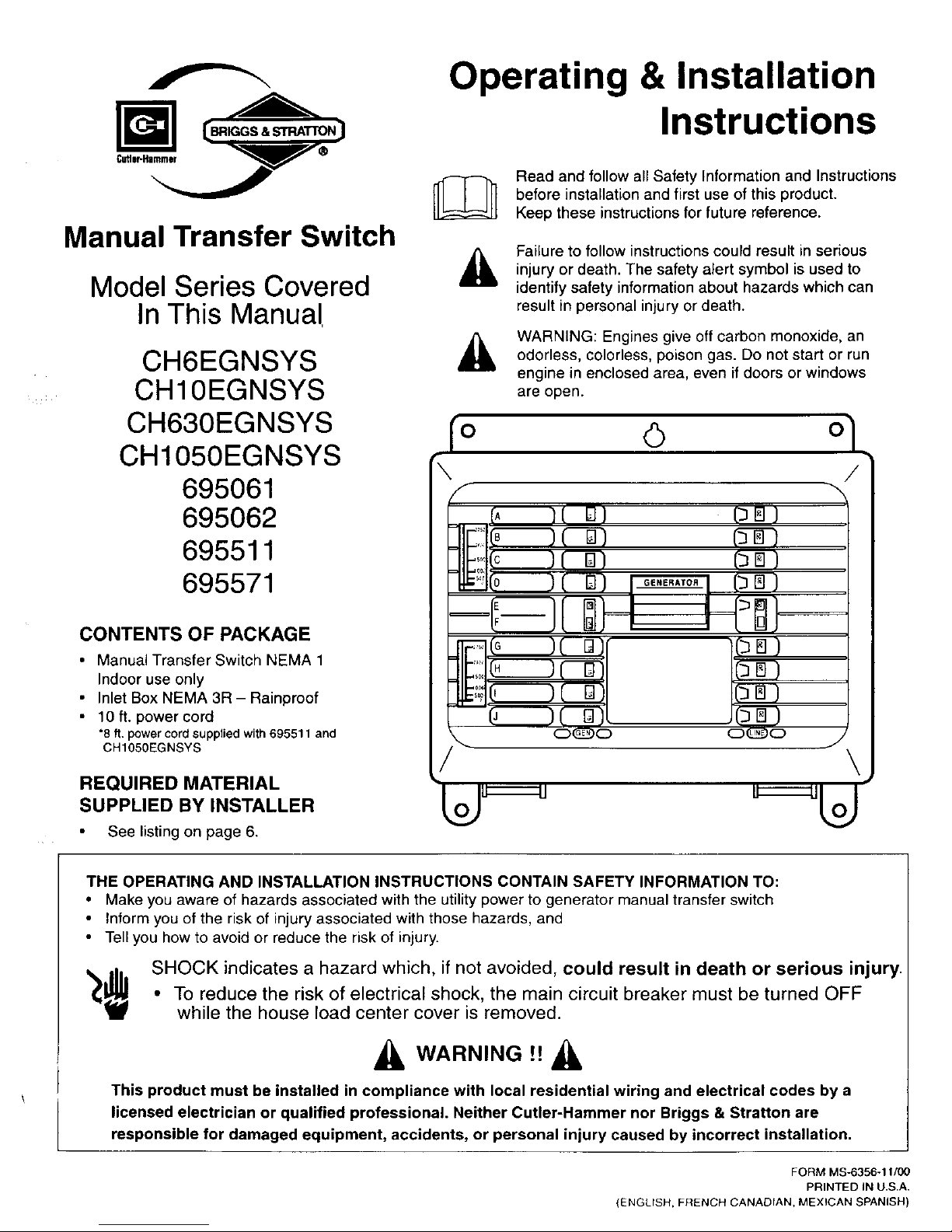
Manual Transfer Switch
Model Series Covered
In This Manual
CH6EGNSYS
CH10EGNSYS
CH630EGNSYS
CH1050EGNSYS
695061
695062
695511
695571
CONTENTS OF PACKAGE
• Manual Transfer Switch NEMA 1
Indoor use only
• Inlet Box NEMA 3R - Rainproof
• 10ft. powercord
*8 ft. power cord supplied with 695511 and
CH105OEGNSYS
REQUIRED MATERIAL
SUPPLIED BY INSTALLER
See listing on page 6.
Operating & Installation
Instructions
Read and follow all Safety Information and Instructions
before installation and first use of this product.
Keep these instructions for future reference.
Failure to follow instructions could result in serious
injury or death. The safety alert symbol is used to
identify safety information about hazards which can
result in personal injury or death.
WARNING: Engines give off carbon monoxide, an
odorless, colorless, poison gas. Do not start or run
engine in enclosed area, even if doors or windows
are open.
IO (_) O 7
\
F
(A ]( D)
JlE:::l(c _(B)
_i0 )(D) [
_(G )( D)I
(_ 1( D)L
GENERATOR
pB)
(_r_)
j_l (_) ,
(_m)
I_) ,
(_)
THE OPERATING AND INSTALLATION INSTRUCTIONS CONTAIN SAFETY INFORMATION TO:
• Make you aware of hazards associated with the utility power to generator manual transfer switch
• Inform you of the risk of injury associated with those hazards, and
• Tell you how to avoid or reduce the risk of injury.
_$ SHOCK indicates a hazard which, if not avoided, could result in death or serious injury.
• To reduce the risk of electrical shock, the main circuit breaker must be turned OFF
while the house load center cover is removed.
_i, WARNING !_ &
This product must be installed in compliance with local residential wiring and electrical codes by a
licensed electrician or qualified professional. Neither Cutler-Hammer nor Briggs & Stratton are
responsible for damaged equipment, accidents, or personal injury caused by incorrect installation.
FORM MS-6356-11/00
PRINTED IN US.A.
(ENGLISH, FRENCH CANADIAN, MEXICAN SPANISH)
Page 2
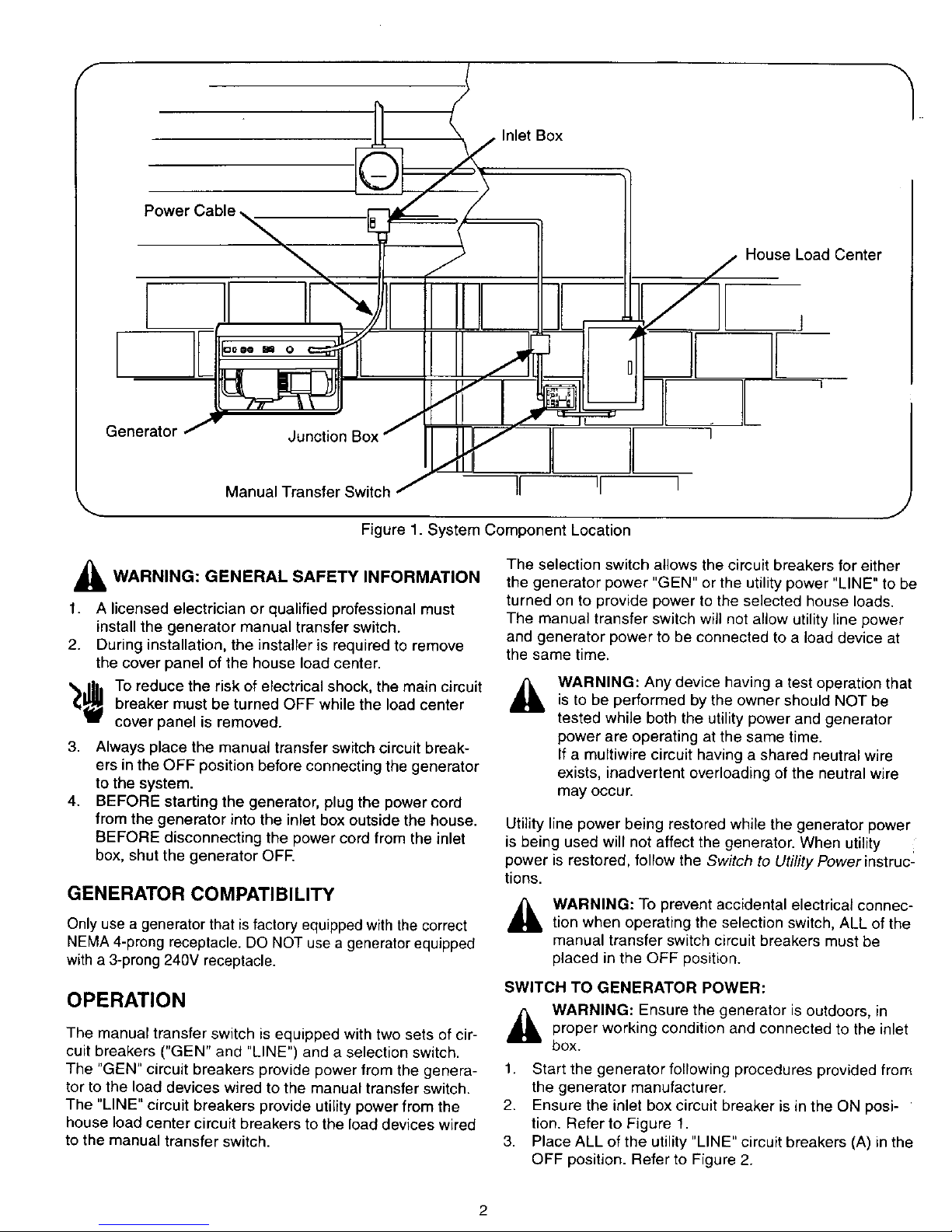
Power Cable
7
" Inlet Box
t I /L
House Load Center
IE
Generator J
JunotionBoxJ
Manual Transfer Switch j
I
I
L
I
I
Figure 1. System Component Location
,_ WARNING: GENERAL SAFETY INFORMATION
1. A licensed electrician or qualified professional must
install the generator manual transfer switch.
2. During installation, the installer is required to remove
the cover panel of the house load center.
'_/_ To reduce the risk of electrical shock, the main circuit
breaker must be turned OFF while the load center
cover panel is removed.
3. Always place the manual transfer switch circuit break-
ers in the OFF position before connecting the generator
to the system.
4. BEFORE starting the generator, plug the power cord
from the generator into the inlet box outside the house.
BEFORE disconnecting the power cord from the inlet
box, shut the generator OFE
GENERATOR COMPATIBILITY
Only use a generator that is factory equipped with the correct
NEMA 4-prong receptacle. DO NOT use a generator equipped
with a 3-prong 240V receptacle.
OPERATION
The manual transfer switch is equipped with two sets of cir-
cuit breakers ("GEN" and "LINE") and a selection switch.
The "GEN" circuit breakers provide power from the genera-
tor to the load devices wired to the manual transfer switch.
The "LINE" circuit breakers provide utility power from the
house load center circuit breakers to the load devices wired
to the manual transfer switch.
The selection switch allows the circuit breakers for either
the generator power "GEN" or the utility power "LINE" to be
turned on to provide power to the selected house loads.
The manual transfer switch will not allow utility line power
and generator power to be connected to a load device at
the same time.
A
WARNING: Any device having a test operation that
is to be performed by the owner should NOT be
tested while both the utility power and generator
power are operating at the same time.
If a multiwire circuit having a shared neutral wire
exists, inadvertent overloading of the neutral wire
may occur.
Utility line power being restored while the generator power
is being used will not affect the generator. When utility
power is restored, follow the Switch to Utifity Powerinstruc_
tions.
_, ARNING: To prevent accidental electrical connec-
tion when operating the selection switch, ALL of the
manual transfer switch circuit breakers must be
placed in the OFF position.
SWITCH TO GENERATOR POWER:
,_ WARNING: Ensure the generator is outdoors, in
proper working condition and connected to the inlet
box.
1. Start the generator following procedures provided from
the generator manufacturer.
2. Ensure the inlet box circuit breaker is in the ON posi-
tion. Refer to Figure 1.
3. Place ALL of the utility "LINE" circuit breakers (A) in the
OFF position. Refer to Figure 2.
2
Page 3
4. Move the selection switch (B) from the utility LINE set-
ting to the GENERATOR setting.
NOTE: This will mechanically prevent the manual transfer
switch "LINE" circuit breakers from being placed in the ON
_osition.
5. Place the desired generator "GEN" circuit breakers (C)
in the ON position.
IMPORTANT: If there is a delay before switching to genera-
tor power during an extended power outage, most or all of
the load devices being powered through the manual trans-
fer switch may start at the same time. To avoid possible
overload damage to the generator, alternate placing loads
on each of the 120 VAC legs of the generator. This is
accomplished by turning the generator circuit breakers ON
one at a time, alternating between the upper and lower cir-
cuit breakers of the manual transfer switch.
Examples:
On the 6 circuit manual transfer switch: Turn on an
upper circuit breaker (labeled "A","B" or "C"), then a
lower circuit breaker (labeled "D", "E" or "F"). Continue
alternating for remaining circuit breakers.
On the 10 circuit manual transfer switch: Turn on an
upper circuit breaker (labeled "A" through "E'), then a
lower circuit breaker (labeled "F" through "J"). Continue
alternating for remaining circuit breakers.
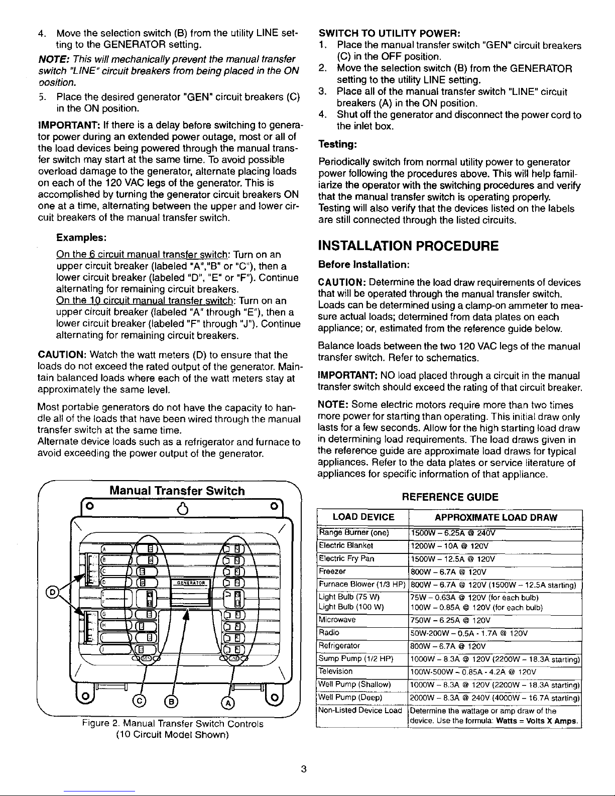
CAUTION: Watch the watt meters (D) to ensure that the
loads do not exceed the rated output of the generator. Main-
tain balanced loads where each of the watt meters stay at
approximately the same level.
Most portable generators do not have the capacity to han-
dle all of the loads that have been wired through the manual
transfer switch at the same time.
Alternate device loads such as a refrigerator and furnace to
avoid exceeding the power output of the generator.
f
Manual Transfer Switch
o <3
I)
\
© ®
Figure 2. Manual Transfer Switch Controls
(10 Circuit Model Shown)
SWITCH TO UTILITY POWER:
1, Place the manual transfer switch "GEN" circuit breakers
(C) in the OFF position.
2. Move the selection switch (B) from the GENERATOR
setting to the utility LINE setting.
3. Place all of the manual transfer switch "LINE" circuit
breakers (A) in the ON position.
4. Shut off the generator and disconnect the power cord to
the inlet box.
Testing:
Periodically switch from normal utility power to generator
power following the procedures above. This will help famil-
iarize the operator with the switching procedures and verify
that the manual transfer switch is operating properly.
Testing will also verify that the devices listed on the labels
are still connected through the listed circuits.
INSTALLATION PROCEDURE
Before Installation:
CAUTION: Determine the load draw requirements of devices
that will be operated through the manual transfer switch.
Loads can be determined using a clamp-on ammeter to mea-
sure actual loads; determined from data plates on each
appliance; or, estimated from the reference guide below.
Balance loads between the two 120 VAC legs of the manual
transfer switch. Refer to schematics.
IMPORTANT: NO load placed through a circuit in the manual
transfer switch should exceed the rating of that circuit breaker.
NOTE: Some electric motors require more than two times
more power for starting than operating. This initial draw only
lasts for a few seconds. Allow for the high starting load draw
in determining load requirements. The load draws given in
the reference guide are approximate load draws for typical
appliances. Refer to the data plates or service literature of
appliances for specific information of that appliance.
REFERENCE GUIDE
LOAD DEVICE
Range Burner (one)
Electric Blanket
Electric Fry Pan
Freezer
Furnace Blower (1/3 HP)
Light Bulb (75 W)
Light Bulb (100 W)
Microwave
Radio
Refrigerator
Sump Pump (1/2 HP)
Television
Well Pump (Shallow)
Well Pump (Deep)
Non-Listed Device Load
APPROXIMATE LOAD DRAW
1500W - 6.25A @240V
1200W - 10A @ 120V
1500W - 12.5A @ 120V
BOOW- 6.7A @ 120V
BOOW- 6.7A @ 120V (1500W - 12.5A starting)
75W- 0.63A @ 120V (for each bulb)
100W - 0.85A @ 120V (for each bulb)
?50W - 6.25A @ 120V
50W-200W - 0.5A - 1.7A @ 120V
B00W - 6.7A @ 120V
1000W - 8.3A @ 120V (2200W- 18.3A starting/
100W-500W - 0.85A -4.2A @ 120V
1000W - 8.3A @ 120V (2200W - 18.3A starting)
_000W - 8.3A @ 240V (4000W - 16.7A starting)
Determine the wattage or amp draw of the
device. Use the formula: Watts = Volts X Amps.
Page 4
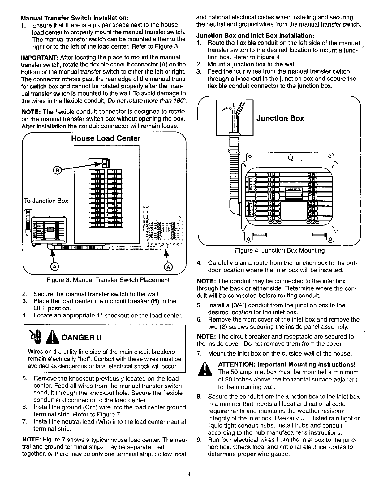
Manual Transfer Switch Installation:
1. Ensure that there is a proper space next to the house
load center toproperly mount the manual transfer switch.
The manual transfer switchcan be mounted either to the
right or to the leftof the load center. Refer to Figure 3.
IMPORTANT: After locating the place to mount the manual
transferswitch, rotatethe flexible conduit connector (A) on the
bottomor the manual transfer switchto either the left or right.
The connector rotates past the rear edge ofthe manual trans-
fer switch box and cannot be rotated properly after the man-
ual transfer switchis mounted tothe wall. Toavoid damage to
thewires in the flexible conduit, Do not rotate more than 180°.
NOTE: The flexible conduit connector is designed to rotate
on the manual transfer switch box without opening the box.
After installation the conduit connector will remain loose.
f
House Load Center
r-oJunction Box
=_-=÷='_" _,
i_ - _'f¥_--oP/- •
7- __-_
® ®
J
Figure 3. Manual Transfer Switch Placement
2. Secure the manual transfer switch to the wall.
3. Place the load center main circuit breaker (B) in the
OFF position.
4. Locate an appropriate 1" knockout on the load center.
Wires on the utility lineside of the main circuit breakers
remain electrically "hot". Contact with these wires must be
avoided as dangerous or fatal electrical shock will occur.
5. Remove the knockout previously located on the load
center. Feed all wires from the manual transfer switch
conduit through the knockout hole. Secure the flexible
conduit end connector to the load center.
6. Install the ground (Grn) wire into the load center ground
terminal strip. Refer to Figure 7.
7. Install the neutral lead (Wht) into the load center neutral
terminal strip.
NOTE: Figure 7 shows a typical house load center. The neu-
tral and ground terminal strips may be separate, tied
together, or there may be only one terminal strip. Follow local
and national electrical codes when installing and securing
the neutral and ground wires from the manual transfer switch.
Junction Box and Inlet Box Installation:
1. Route the flexible conduit on the left side of the manual
transfer switch to the desired location to mount a junc-,
tion box. Refer to Figure 4.
2. Mount a junction box to the wall.
3. Feed the four wires from the manual transfer switch
through a knockout in the junction box and secure the
flexible conduit connector to the junction box.
Junction Box
Figure 4. Junction Box Mounting
4. Carefully plan a route from the junction box to the out-
door location where the inlet box will be installed.
NOTE: The conduit may be connected to the inlet box
through the back or either side. Determine where the con-
duit will be connected before routing conduit.
5. Install a (3/4") conduit from the junction box to the
desired location for the inlet box.
6. Remove the front cover of the inlet box and remove the
two (2) screws securing the inside panel assembly.
NOTE: The circuit breaker and receptacle are secured to
the inside cover. Do not remove them from the cover.
7. Mount the inlet box on the outside wall of the house.
A TTENTION: Important Mounting instructions!
The 50 amp inlet box must be mounted a minimum
of 30 inches above the horizontal surface adjacent
to the mounting wall.
8.
9,
Secure the conduit from the junction box to the inlet box
in a manner that meets all local and national code
requirements and maintains the weather resistant
integrity of the inlet box. Use only U.L listed rain tight or
liquid tight conduit hubs. Install hubs and conduit
according to the hub manufacturer's instructions.
Run four electrical wires from the inlet box to the junc-
tion box. Check local and national electrical codes to
determine proper wire gauge.
4
Page 5
Junction Box
I Inlet Box \
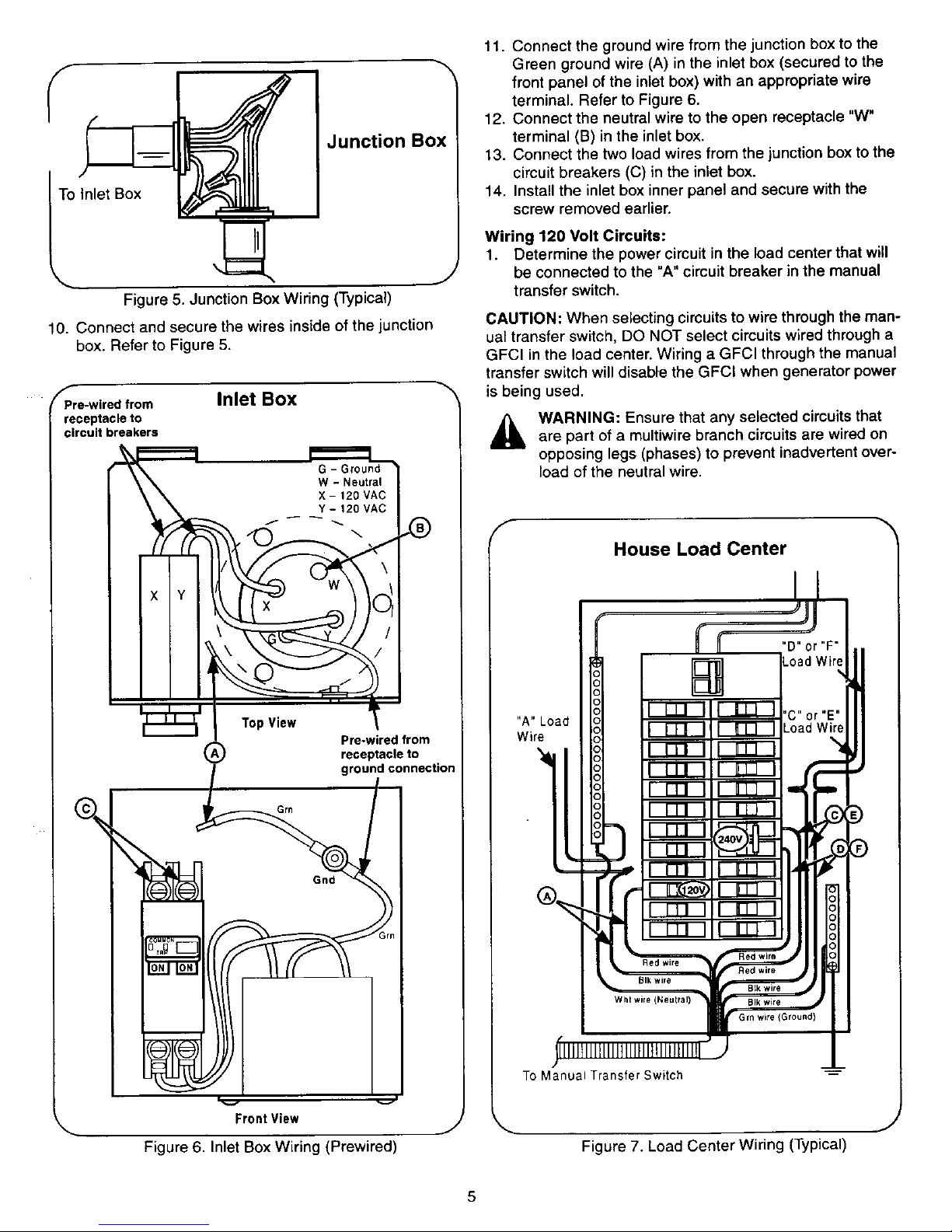
Figure 5. Junction Box Wiring (Typical)
J
10. Connect and secure the wires inside of the junction
box. Refer to Figure 5.
_Pre-wfred from
receptacle to
circuit breakers
Inlet Box
t..==-1
G - Ground
W - Neutral
X - 120 VAC
Y - 120 VAC
TopView _
Pre-wired from
(_) receptacle to
ground connectio_
Grn
FrontView
Figure 6, Inlet Box Wiring (Prewired)
J
11. Connect the ground wire from the junction box to the
Green ground wire (A) in the inlet box (secured to the
front panel of the inlet box) with an appropriate wire
terminal. Refer to Figure 6.
12. Connect the neutral wire to the open receptacle "W"
terminal (B) in the inlet box.
13. Connect the two load wires from the junction box to the
circuit breakers (C) in the inlet box.
14. Install the inlet box inner panel and secure with the
screw removed earlier.
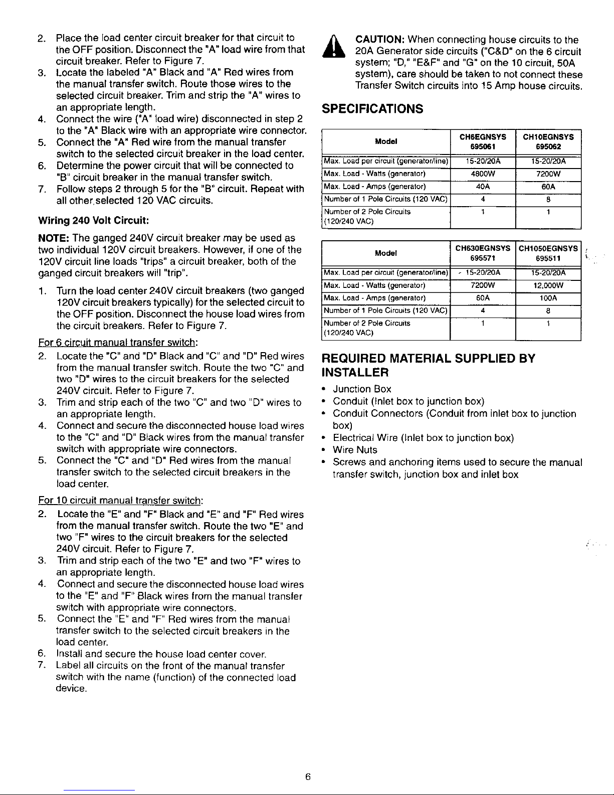
Wiring 120 Volt Circuits:
1. Determine the power circuit in the load center that will
be connected to the "A" circuit breaker in the manual
transfer switch.
CAUTION: When selecting cimuits to wire through the man-
ual transfer switch, DO NOT select circuitswired through a
GFCI in the load center. Wiring a GFCl through the manual
transfer switch will disable the GFCI when generator power
is being used.
A ARNING: Ensure that any selected circuitsthatare part of a multiwire branch circuits are wired on
opposing legs (phases) to prevent inadvertent over-
load of the neutral wire.
F
House Load Center
To Manual Transfer Switch
Figure 7. Load Center Wiring (Typical)
Page 6
2. Placetheloadcentercircuitbreakerforthatcircuitto
theOFFposition.Disconnectthe"A"loadwirefromthat
circuitbreaker.RefertoFigure7.
3. Locatethelabeled"A"Blackand"A"Redwiresfrom
themanualtransferswitch.Routethosewirestothe
selectedcircuitbreaker.Trimandstripthe"A"wiresto
anappropriatelength.
4. Connectthewire("A"loadwire)disconnectedinstep2
tothe"A"Blackwirewithanappropriatewireconnector.
5. Connectthe"A"Redwirefromthemanualtransfer
switchtotheselectedcircuitbreakerintheloadcenter.
6. Determinethepowercircuitthatwillbeconnectedto
"B"circuitbreakerinthemanualtransferswitch.
7. Followsteps2through5forthe"B"circuit.Repeatwith
allotherselected120VACcircuits.
Wiring 240 Volt Circuit:
NOTE: The ganged 240V circuit breaker may be used as
two individual 120V circuit breakers. However, if one of the
120V circuit line loads "trips" a circuit breaker, both of the
ganged circuit breakers will "trip".
1.
Turn the load center 240V circuit breakers (two ganged
120V circuit breakers typically) for the selected circuit to
the OFF position. Disconnect the house load wires from
the circuit breakers. Refer to Figure 7.
For 6 circuit manual transfer switch:
2. Locate the "C" and "D" Black and "C" and "D" Red wires
from the manual transfer switch. Route the two "C" and
two "D" wires to the circuit breakers for the selected
240V circuit. Refer to Figure 7.
3. Trim and strip each of the two "C" and two "D" wires to
an appropriate length.
4. Connect and secure the disconnected house load wires
to the "C" and "D" Black wires from the manual transfer
switch with appropriate wire connectors.
5. Connect the "C" and "D" Red wires from the manual
transfer switch to the selected circuit breakers in the
toad center.
For 10 circuit manual transfer switch:
2. Locate the "E" and "F" Black and "E" and "F" Red wires
from the manual transfer switch. Route the two "E" and
two "F" wires to the circuit breakers for the selected
240V circuit. Refer to Figure 7.
3. Trim and strip each of the two "E" and two "F" wires to
an appropriate length.
4. Connect and secure the disconnected house load wires
to the "E" and "F" Black wires from the manual transfer
switch with appropriate wire connectors.
5. Connect the "E" and "F" Red wires from the manual
transfer switch to the selected circuit breakers in the
load center.
6. Install and secure the house load center cover.
7. Label all circuits on the front of the manual transfer
switch with the name (function) of the connected load
device.
A
CAUTION: When connecting house circuits to the
20A Generator side circuits ("C&D" on the 6 circuit
system; "D," "E&F" and "G" on the 10 circuit, 50A
system), care should be taken to not connect these
Transfer Switch circuits into 15 Amp house circuits.
SPECIFICATIONS
CH6EGNSYS CH10EGNSYS
Model
695061 695062
Max. Load per circuit (generator/lin_ 15-20/20A 15-20/20A
Max. Load - Watts (generator) 4800W 7200W
Max. Load - Amps (generator) 40A 60A
Number of 1 Pole Circuits (120 VAC) 4 8
Number of 2 Pole Circuits 1 1
120/240 VAC)
CH630EGNSYS CHI050EGNSYS
Model
695571 695511
iMax. Load per circuit (generatodline - 15-20/20A 15-20/20A
;Max. Load - Watts (generator) 7200W 12,000W
k,lax. Load - Amps (generator) 60A 100A
Number of 1 Pole Circuits (120 VAC) 4 8
Number of 2 Pole Circuits 1 1
(120/240 VAC)
i •
REQUIRED MATERIAL SUPPLIED BY
INSTALLER
• Junction Box
• Conduit (Inlet box to junction box)
• Conduit Connectors (Conduit from inlet box to junction
box)
Electrical Wire (Inlet box to junction box)
• Wire Nuts
• Screws and anchoring items used to secure the manual
transfer switch, junction box and inlet box
Page 7
TROUBLESHOOTING
Problem Possible Cause Possible Solution
Generator slows down when loads 1. Generator is overloaded 1. Check watt meters to determine possible over-
!are connected, loads. Turn circuit breakers OFF to balance or
reduce loads.
Generator runs but no power to 1. Check and reset circuit breakers in inlet box.
load devices.
Only some load devices work on
lenerator power.
Unable to turn manual transfer
switch circuit breakers ON.
240V manual transfer switch circuit
breaker trips.
1. Inlet box cimuit breakers are notin the ON
position.
2. Manual transfer switch selector is in incorrect
position and/or circuit breakers are in incorrect
position.
3. Poor or no connection between generator and
inlet box.
4. Generator circuit breaker(s) "tripped."
1. Manual transfer switch circuitbreaker(s) are OFF
2. Load devices are not plugged into connected
circuit outlets.
1. Selection switch is in incorrect position.
1. One or both of the 120V lines is overloaded or
shorted to ground.
2. Check manual transfer switch for correct selec-
tion switch position ("GEN") and/or turn circuit
breakers ON.
3. Check power cord and connections between
generator and inlet box.
4. Reset generator circuit breaker(s).
1. Check circuit breakers.
2. Verify that load devices are plugged into cor-
rsctoutlets.
1. Verify selection switch is placed in proper posi-
tion. Set circuit breakers.
1. Determine which line(s) is overloaded or
shorted. Disconnect load or correct short.
NOTE: If one of the 120V load circuits trips the
circuit breaker, both of the tied circuit breakers
will trip.
No power to the load device when 1. The house load center circuit breaker orthe 1. Check both the house load center circuit
the manual transfer switch selector manual transfer switch circuit breaker for that breaker and the manual transfer switch circuit
is in "LINE" operation (generator load device is tripped, breaker that the load device is powered
OFF and not being used), through.
Limited Warranty
Cuttler-Hammer Inc. warrants that the Cutler-Hammer/Briggs & Stratton Manual Power Transfer Switches (CH6EGNSYS/695061,
CH10EGNSYS/695062, CH630EGNSYS/695571 and CH1050EGNSYS/695511) and power inlet boxes, and power cords and flange kits
(695520, 695521, 695522, 695523, 695649, CH6EGENCORD, CH6EGEN10CORD, CH6EGEN25CORD, CH10EGEN25CORD, 695514,
695066, 695067, CHEGENFKIT, CH6EGENPIB and CH10EGENPIB) will be free from failure due to defects in workmanship and material for
a period of 5 years from date of purchase by the original retail purchaser under normal care and proper usage in a residential installation.
In the event the product fails to comply with this warranty Cutler-Hammer lec. will, at its option, repair or replace the defective product, or
component(s) or part(s) thereof. To obtain warranty service the original retail purchaser should return the product to the place of pur-
chase or deliver the product prepaid to Cutler-Hammer Inc. at the address set forth below. Proof of purchase in the form of a receipt or
invoice which is evidence that the unit is within the warranty period must be presented to obtain warranty service.
Notice requirements and limitations applicable to Cutler-Hammer Inc. warranties are:
A. This warranty does not cover failure or damage due to improper storage, installation, operation, maintenance, alteration, repair, acci-
dent, misuse, abuse or negligence. This warranty does not cover reimbursement for labor, transportation, gaining access, removal,
installation, temporary power, or any other expenses which may be incurred in connection with repair or replacement.
B. REPAIR OR REPLACEMENT AS PROVIDED UNDER THIS WARRANTY IS THE EXCLUSIVE REMEDY OF THE PURCHASER
AND THE LIMIT OF THE LIABILITY OF CUTLER-HAMMER INC. WiTH RESPECT TO THIS PRODUCT, WHETHER IN CON-
TRACT, IN TORT (INCLUDING NEGLIGENCE OR STRICT LIABILITY) OR OTHERWISE. CUTLER-HAMMER INC. DISCLAIMS
ALL OTHER WARRANTIES, INCLUDING WITHOUT LIMITATION, ANY IMPLIED WARRANTY OF MERCHANTABILITY OR FIT-
NESS FOR A PARTICULAR PURPOSE. IN NO EVENT WILL CUTLER-HAMMER INC. BE LIABLE FOR ANY OTHER DAMAGES,
WHETHER DIRECT, INCIDENTAL, CONSEQUENTAL OR OTHERWISE.
C. With respect to products purchased by consumers ofthe United States for personal use, the implied warranties, including but not lim-
ited to the warranties of merchantability and of fitness for a particular purpose, are not excluded but are limited to the duration of the
applicable warranty period. Some states do not allow limitations on the duration of an implied warranty, so the above limitation may
not apply to buyer. Similarly, some states do not allow the exclusion or limitation of incidental or consequential damages, so the
above excision or limitation may not apply to buyer. This warranty gives buyer specific legal rights, and buyer may also have other
rights which may vary from state to state.
This warranty covers residential use of Cutler-Hammer/Briggs & Stratton Manual Power Transfer Switches and excludes any commercial
applications.
CUTLER-HAMMER INC.
1000 CHERRINGTON PARKWAY
MOON TOWNSHIP, PENNSYLVANIA 15108
www.briggsandstratton.com
1-800-356-1243
www.ch.cutler-hammer.com
7
Page 8
SCHEMATICS
f
Flexible Conduit to
Junction Box
SCHEMATIC
(6 Circuit Model)
Manual Transfer Switch
Inlet Box Receptacle
240 VAC
Flexible Conduit to
House Load Center
F
Red Wires
A
G-Ground f
W - Neutral
X - 120 VAC
Y - 120 VAC
F
Black Wires
Grn
Wht
Rating:
A through C - 120VAC
D through F - 120VAC
C and D - 240VAC
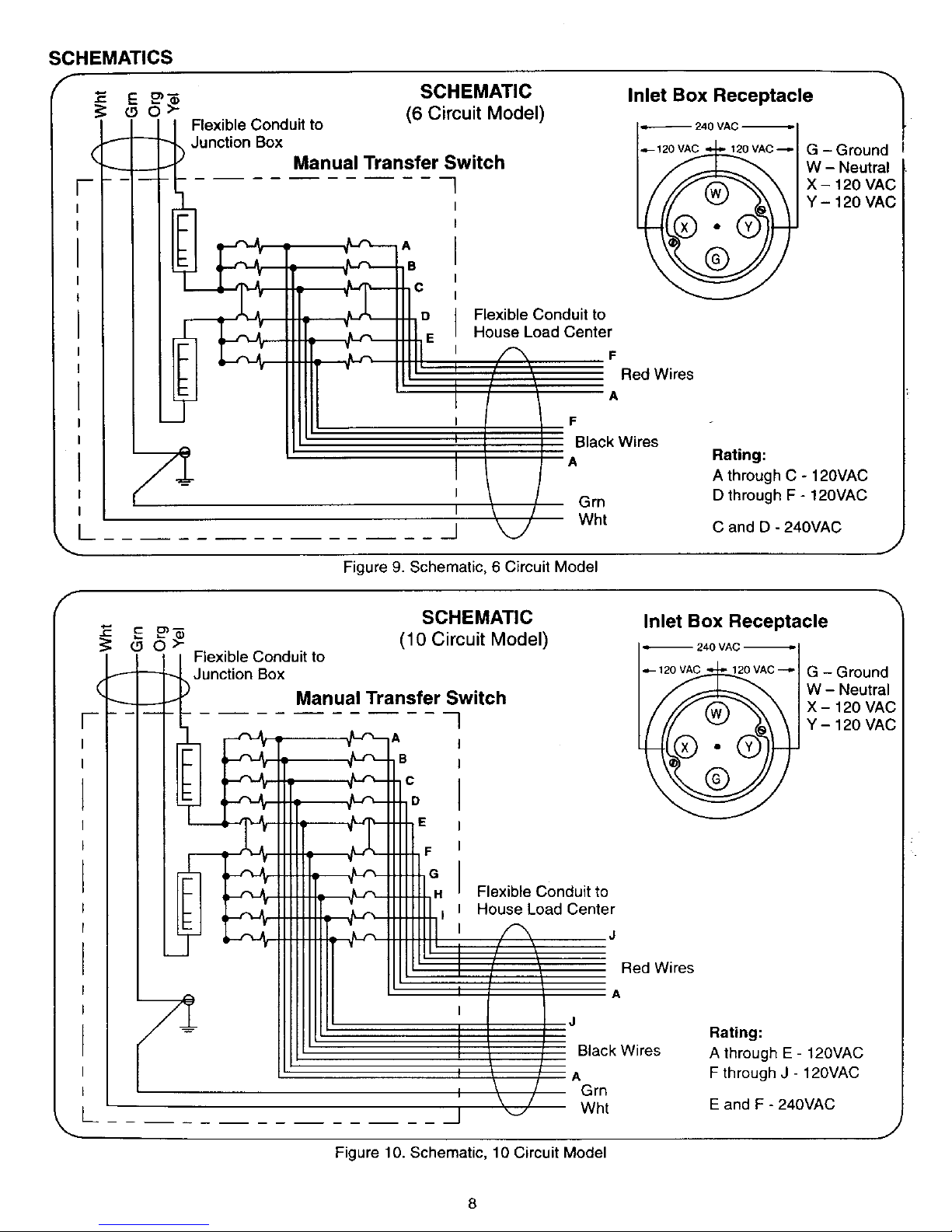
Figure 9. Schematic, 6 Circuit Model
J
F
/
SCHEMATIC
(10 Circuit Model)
Flexible Conduit to
Junction Box
Manual Transfer Switch
E
Flexible Conduit to
House Load Center
Inlet Box Receptacle
240 VAC
_- 120_VAC --="
\@/
G - Ground
W - Neutral
X - 120 VAC
Y - 120 VAC
Red Wires
A
Black Wires
A
Grn
Wht
Rating:
A through E - 120VAC
F through J - 120VAC
E and F - 240VAC
Figure 10. Schematic, 10 Circuit Model
Page 9

Commutateur manuel
Serie de modeles
present_e dans ce guide
CH6EGNSYS
CH10EGNSYS
CH630EGNSYS
CH1050EGNSYS
695061
695062
695511
695571
CONTENU DE L'EMBALLAGE
• Commutateur manuel NEMA 1
pour usage & I'interieur seulement
•BoTte d'entre_e NEMA 3R - & I'#preuve
de la pluie
• Cordon d'alimentation de 10 pi
*cordon d'alimentation de 8 pi fourni avec
module 695511 et CH1050EGNSYS
Guide de fonctionnement
et d'installation
A
Avant d'instailer ou utiliser ce produit pour la premiere
lois, lire et observer les renseignements et instructions
de securite.
Conserver cette notice pour r_ference future.
La non-observation de ces instructions pourrait
entrafner des blessures graves ou m6me la mort. Le
pictogramme de miss en garde de securitd d_signe
des renseignements sur les dangers pouvant
entrafner des blessures graves ou la mort.
AVERTISSEMENT : Les moteurs d_gagent du
monoxyde de carbons ; un gaz toxique, inodore st
incolore. Ne pas ddmarrer ou fairs fonctionner un
moteur dans un endroit ferme, m_me en presence de
portes ou fen_tres ouvedes.
[o O o"
\
r
/
(0 )(D) pr_)
i0 )(_) io..,.,,o.i (_D)
=['F--)(
(_ 1( I_)L
I_D)
(_B)
MATI_RIEL REQUIS FOURNI
PAR L'INSTALLATEUR
Voir la liste a la page 6.
CE GUIDE DE FONCTIONNEMENT ET D'INSTALLATION CONTIENT DES RENSEIGNEMENTS RELATIFS ._.LA
SECURITE VISANT A :
• Vous prevenir des dangers inherents au courant de secteur aliment_ au commutateur manuel de la g_n_ratrice ;
• Vous renseigner sur les risques de blessures d_coulant de ces dangers ; et
• Vous indiquer comment eviter ou r_duire le risque de blessures.
Le pictograrnme CHOC indique un danger lequel, si non _vit_, peut entrainer la mort ou des
_j blessures graves.
• Pour r_duire le risque de chocs _lectriques le disjoncteur principal doit _tre mis hors circuit
pendant que le couverc e du tab eau de distribution est enleve.
_I, AVERTISSEMENT !! _I,
Ce produit dolt _tre installd par un maitre dlectricien ou un technicien agrdd conformdment aux
regles de I'art du c&blage darts les habitations et aux codes d'electricit_ Iocaux. Cutler-Hammer et
Briggs & Stratton d_ciinent toute responsabilit_ quant aux avaries d'dquipement, accidents ou
blessures caus_es par une installation erronde.
FORMULAIRE MS-6356-11/00
IMPRIME AUX r_.-U.
ANGLAIS, FRAN_AIS (CANAOA), ESPAGNOL (MEXlQUE)
Page 10

C&ble d'alimentation
Gen_ratrice 7
Tableau de distribution
Boite de jonction
Commutateur manuel J
Figure 1. Rep6rage des composants du syst_me
_k AVERTISSEMENT: RENSEIGNEMENTS
GI_NC:RAUX DE St_CURITF:
1. Seul un maitre electricien ou un technicien competent
dolt installer le commutateur manuel de generatrice.
2. Au cours de I'installation, I'installateur doit enlever le
couvercle du tableau de distribution.
',_$ Pour r6duire le risque de chocs electriques, le
disjoncteur principal dolt 6tre mis en position OFF
pendant que le couvercle du tableau de distribution
est enleve.
3. Mettre toujours les disjoncteurs du commutateur
manuel en position OFF avant de brancher la
ge_n_ratrice au systeme.
4. AVANT de demarrer la gen_ratrice, brancher le cordon
d'alimentation de la gen_ratrice clans la boite d'entr_e
situee & I'ext_rieur de la maison. AVANT de d_brancher
le cordon d'alimentation de la bofte d'entree, arr6ter la
gq#n_ratrice.
COMPATIBILITI_ DE LA GI_NI_RATRICE
Utiliser uniquement une g_neratrice equipee en usine de la
prise appropriee NEMA & 4 lames. NE PAS utiliser une
g_n_ratrice equipee d'une prise 240 V &3 lames.
EXPLOITATION
Le commutateur manuel est muni de deux series de
disjoncteurs, ,, GEN ,, et ,, LINE ,,, ainsi que d'un selecteur.
Les disjoncteurs - GEN ,,conduisent le courant de la
g_neratrice vers les appareils branch_s au commutateur
manuel qui constituent la charge. Les disjoncteurs ,, LINE ,,
alimentent le courant de secteur des disjoncteurs du
tableau de distribution vers les appareils branch_s au
commutateur manuel qui constituent la charge.
Le s_lecteur permet la mise sous tension des disjoncteurs
de la generatrice ,<GEN ,, ou du courant de secteur
,, LINE ,, pour alimenter les appareils qui constituent la
charge. Le commutateur manuel ne permet pas le couplag
d'une charge simultan_ment sur le courant de secteur et 16
courant produit par la g_n_ratrice.
&
AVERTISSEMENT : I'utilisateur ne devrait PAS
effectuer d'essai sur un appareil quelconque
pendant I'exploitation simultan_e du courant de
secteur et du courant produit par la g6n_ratrice.
Dans un circuit a plusieurs conducteurs et & neutre
partage, le conducteur neutre peut subir une sur-
charge accidentelle.
Si le courant de secteur se r_tablit pendant rutilisation du
courant produit par la g_n_ratrice, celle-ci n'en sera pas
touchee. Lorsque le courant de secteur se r6tablit, suivre
les instructions Commutation au courant de secteur.
AVERTISSEMENT : Pour _viter toute connexion
_lectrique accidentelle pendant la manipulation du
s_lecteur, TOUS les disjoncteurs du commutateur
manuel doivent _tre mis en position OFF.
COMMUTATION AU COURANT PRODUIT PAR LA
GENC=RATRICE
,_ AVERTISSEMENT : S'assurer de placer la genera-
trice a I'exterieur, de verifier son bon etat de fonc-
tionnement et de la brancher & la boTte d'entree.
1. D_marrer la generatrice conformement &la notice du
fabricant.
2. S'assurer de mettre le disjoncteur de la boite d'entree
en position ON. Voir la figure 1.
3. Mettre TOUSles disjoncteurs ,<LINE ,, (A) en position
OFE Voir la figure 2.
Page 11

4. Deplacerles61ecteur(B)delapositionLINE&la
positionGENERATOR.
REMARQUE : Ceci emp#chera les disjoncteurs ,,LINE ,,
du commutateur manuel de se me#re en position ON.
5. Mettre les disjoncteurs ,, GEN ), requis de la
generatrice (C) & la position ON.
IMPORTANT : S'il y a un d_lai de commutation au courant
produit par la generatrice, au cours d'une panne prolongee,
la plupart des appareils alimentes par le commutateur
manuel peuvent entrer en jeu simultanement. Pour eviter
tout dommage dl3 & la surcharge de la generatrice, alterner
les charges sur chacun des trongons de 120 Vca de la
generatrice. On effectue cette manoeuvre en mettant sous
tension les disjoncteurs de la generatrice, un & un et en
alternant entre les disjoncteurs superieurs et inferieurs du
commutateur manuel.
Exemples:
Sur le commutateur manuel & 6 circuits : Mettre sous
tension un disjoncteur superieur (marque ,, A ,),,, B ,,
ou ,, C -), ensuite un disjoncteur inferieur (marque
,, D ,,, ,, E ,, ou ,, F ,)). Continuer cette alternance pour
le reste des disjoncteurs.
Sur le commutateur manuel & 10 circuits : Mettre sous
tension un disjoncteur superieur (marque <,A ,, &
,, E ,,), ensuite un disjoncteur inferieur (marque ,, F ), &
,, J ,,). Continuer cette alternance pour le reste des
disjoncteurs.
MISE EN GARDE : Surveiller les wattm_tres (D) pour
s'assurer que les charges n'excedent pas la puissance
nominale de la generatrice, Maintenir des charges reparties
egalement o_Jchacun des wattmetres se tient & peu pres au
meme niveau.
La plupart des generatrices portatives ne peuvent suffire
simultan_ment & toutes les charges couplees par I'interme-
diaire du commutateur manuel.
Alterner les charges d'appareils, tels que refrig_rateur et
generateur d'air chaud pour _viter d'exc_der la puissance
de la generatrice.
Cemmutateur manuel
© ® ®
Figure 2. Commandes du commutateur manuel
(Modele & 10 circuits)
COMMUTATION AU COURANT DE SECTEUR
1. Mettre les disjoncteurs du commutateur manuel
,, GEN ,, (C) en position OFF.
2. Depiacer le selecteur (B) de Japosition GENERATOR &
la position LINE.
3. Mettre tousles disjoncteurs ,, LINE )) (A) du commu-
tateur manuel a la position ON.
4. Arr_ter la g_neratrice et debrancher le cordon
d'alimentation de la boffe d'entr_e.
Essai:
Commuter periodiquement entre courant de secteur et
courant produit par la gen6ratrice en suivant les instructions
donnees ci-dessus. Ceci permettra & ruti}isateur de mieux
connaTtre les procedures de commutation et s'assurer du
bon fonctionnement du commutateur manuel.
I_essai permettra aussi de verifier que tous les appareils
designes par les _tiquettes respectives sont toujours
branches aux circuits respectifs.
PROCEDURE D'INSTALLATION
Avant I'installation :
MISE EN GARDE : D_terminer les valeurs d'appel de cou-
rant des appareils qui seront couples sur le commutateur
manuel. On peut determiner les charges & I'aide d'une pince
amp_remetre pour mesurer lescharges r_elles, les pr_lever
sur la plaque signal_tique de chaque appareil, ou les estimer
& I'aide du guide de reference montre ci-dessous.
Repartir egalement les charges entre les deux tron£:onsde
120 Vca du commutateur manuel. Consulter les schemas.
IMPORTANT : AUCUNE charge sur un circuit passant par le
commutateur manuel ne devrait exceder le courant nominal
du disjoncteur de ce circuit.
REMARQUE : Certains moteurs debitent plus de deux fois
la puissance au demarrage qu'en cours de fonctionnement.
Cet appel de courant initial dure seulement quelques
secondes. Pour d_terminer la charge requise, tenir compte
de cette valeur superieure. Le guide de r_ference donne
des valeurs d'appel de courant approximatives pour des
appareils types. Consulter les plaques signaletiques ou la
documentation d'entretien des appareils pour des
renseignements plus pertinents.
GUIDE DE R#F#RENCE
APPAREIL
BrQleur de poele (un)
Couverture chauffante
Po61on electrique
Cong_lateur
Ventilateur de gen_ra-
teur d'air chaud (1/3 H.E
Ampoule (75 W)
Ampoule (100 W)
Four micro-ondes
Radio
R_frig6rateur
Pompe de puisard
(1/2 H.E)
Televiseur
Pompe de puits (peu
profond)
Pompe de puits (profond)
Charge non d_finie
APPEL DE COURANT APPROXlMATIF
500 W - 6,25 A sous 240 V
200W 10 A sous 120 V
500 W - 12,5 A sous 120 V
800 W = 6,7A sous 120 V
800 W - 6,7A sous 120 V
(1 500 W - 12,5 A au demarrage)
75 W - 0,63 A sous 120 V (par ampoule)
100 W - 0,85 A sous 120 V (par ampoule)
750 W - 6,25 A sous 120 V
50W- 200 W - 0,5 A - 1,7 A sous 120 V
800 W - 6,7A sous 120 V
000 W - 8,3 A sous 120 V
(2 200 W - 18,3 A au d_marrage)
100 W-500 W - 0,85 A - 4,2 A sous 120 V
000 W - 8,3 A sous 120 V
(2 200 W 18,3 A au demarrage)
2 (300 W - 8,3 A sous 240 V
(4 000 W - 16,7 A au d#rnarrage)
Determiner rappel de courant en amperes ou la
consommation en Watts de I'appareil. Utiliser la
formule : Watts = Volts X Amperes.
Page 12

Installation du commutateur manuel
1. S'assurer de maintenir un d_gagement suffisant autour
du tableau de distribution pour monter le commutateur
manuel de manibre appropri_e. Le commutateur manuel
peut _tre mont_ b droite ou b gauche du tableau de
distribution. Voir la figure 3.
IMPORTANT : Aprbs avoir trouv_ I'emplacement d'installa-
tion du commutateur manuel, tourner le raccord du conduit
flexible (A) situ_ au-dessous du commutateur manuel vers la
gauche ou la droite. Le raccord peut tourner pass_ le bord
arribre du boffier du commutateur manuel et ne peut tourner
de manibre appropri_e une fois que le commutateur manuel
est fix6 au mur. Pour _viter rendommagement des fils dans le
conduit flexible, ne pas tourner le raccord sur plus de 180°.
REMARQUE : Le raccord du conduit flexible est con(;u pour
tourner contre le boffier du commutateur manuel sans
devoir ouvrir le boffier. Aprbs I'installation, la rotation de ce
raccord demeurera libre.
f
Tableau de distribution
Vers bo_te de
onction
2.
3.
4.
Figure 3. Emplacement du commutateur manuel
Assujettir le commutateur manuel au mur.
Mettre le disjoncteur principal du tableau de distribution
(B) en position OFF.
Repdrer un disque d_fon(;able de 1 po (orifice d'entr#e)
sur le tableau de distribution.
Les ills se trouvant du cSte courant de secteur.des disjonc-
teurs principaux demeurent ,, sous tension ,, Eviter tout
contact avec ces ills qui representent un risque de chocs
_lectriques dangereux ou mortels.
5. Enlever le disque d_fon(;able du tableau de distribution.
Passer tousles ills venant du conduit du commutateur
manuel dans I'orifice d'entree. Assujettir le raccord du
conduit flexible au tableau de distribution.
6. Assujettir le fil de terre (Vert) sur le bornier de mise & la
terre du tableau de distribution. Voir la figure 7.
7. Assujettir le ills neutre (Blanc) sur le bornier neutre du
tableau de distribution.
REMARQUE : La figure 7 illustre un tableau de distribution
type. Les borniers de neutre et de terre peuvent _tre
sdpares, raccordes ou il peut y avoir un seul bornier.
Observer les exigences des codes d'_lectricite Iocaux et
nationaux pour I'instaltation des fils neutres et des ills de
terre partant du commutateur manuel.
Installation de la boffe de jonction et de la boffe d'entrde :
1. Acheminer le conduit flexible en partant du c6t_ gauchef
du commutateur manuel vers I'emplacement de la bo_tei
de jonction. Voir la figure 4.
2. Assujettir une boTtede jonction au tour.
3. Passer les quatre ills venant du commutateur manuel &
travers un orifice defongable pratiqu_ dans la boffe de
jonction et assujettir le raccord du conduit flexible & la
bo_te de jonction.
Bo_te de jonction
°6 o]
4.
Figure 4. Montage de la bo_te de jonction
PlanJfier soigneusement un chemin entre la bo_te de
jonction et I'emplacernent exterieur o_ sera installde la
boffe d'entree.
REMARQUE : Le conduit peut _tre raccord_ & la bo_te
d'entree en passant par rarri_re ou run des cStes de la
boffe. Decider de rendroit du raccordement avant de passer
le conduit.
5. Installer un conduit de 3/4 po partant de la bo_tede
jonction vers I'emplacement voulu de la bo{te d'entr_e.
6. Retirer le couvercle de la bo_te d'entr_e et retirer les
deux (2) vis de fixation du panneau int_rieur de la bo_te.
REMARQUE : Le disjoncteur et la prise sont fixes sur le
couvercle interieur. Ne pas les s_parer du couvercle.
7. Installer la boTted'entree sur lemur ext_rieur de la maison.
AI-rENTION : Instructions de montage importantes !
La bo_te d'entr_e de 50 A dolt _tre montee &une
distance minimale de 30 po au-dessus de la sur-
face horizontale adjacente au mur de montage.
8. Assujettir le conduit partant de la bo_te de jonction vers
la bo_ted'entree conform_ment aux codes d'_lectricite
Iocaux et nationaux et, de mani_re & assurer I'integrite
de la resistance aux intemperies de la bo_ted'entree.
Utiliser unJquement des colliers etanches _1la pluie et
aux liquides approuves UL. Installer les colliers et
conduits selon les instructions du fabricant.
9. Faire passer quatre ills entre la bo_te d'entree et la
bo_te de }onction. Consulter les codes d'electricit6
Iocaux et nationaux pour determiner le diametre
approprie (Jauge) des ills.
4
Page 13

f
Boi'te de
jonction
Vers la bofte
d'entree
\
J
Figure 5. C&blage type de la bofte de jonction
10. Raccorder et assujettir les ills se trouvant & rint_rieur
de la boffe de jonction. Voir la figure 5.
C/_blage pr_mont6
entre la prise et
la borne de terre
BoTte d'entr_e
t_
les dis _ncteur=
Vert
Vue de face
Figure 6. Bo_ted'entr6e (c_,btage pr_mont_)
J
cLsL
11. Raccorder le fil de terre venant de la boffe de jonction
au fil de terre vert (A) dans la bo_te d'entrde (assujetti
au couvercle avant de la bo_te d'entree) & I'aide d'un
connecteur appropri6.
Voir la figure 6.
12. Raccorder le fil neutre _.la borne (B) de la prise ,<W >,
dans la boite d'entr6e.
13. Raccorder les deux ills de charge venant de la bo_te de
jonction aux disjoncteurs (C) dans la boi'te d'entr_e.
14. Installer le panneau interieur de la bofte d'entr_e et
serrer la vis enlev6e au pr_alable.
C_blage des circuits 120 Volts :
1. D_terminerle circuitdu tableau de distributionqui sera
raccord_aux disjoncteurs. A ,, du commutateurmanuel.
MISE EN GARDE : Au cours de la sdlection des circuits
c&bler au commutateur manuel, NE PAS s_lectionner les
circuits du tableau de distribution qui auraient passer dans
un disjoncteur differentiel. Le c&blage d'un disjoncteur
differentiel passant par le commutateur manuel mettra le
disjoncteur diff_rentiel hors circuit Iorsqu'on utilise le
courant produit par la generatrice.
,_ AVERTISSEMENT : S'assurer d'effectuer un
c&blage en phases oppos_es de tout circuit
s_lectionne qui fait partie d'une derivation &
plusieurs conducteurs. Cette mesure vise &eviter la
surcharge accidentelle du fil neutre.
Tableau de distribution
I _ _ charge
I I_1 I ILl IJl I ,,g. ou,
ilool p,F,,
I I°1 , f i , i _ n i Fil de
Filde I1 1,
charge<,A"1101 IILUI II_ILL.q..JI" c,, ou
Jill "
11ILL c
Fil noir
ors e commutateur manuel
Figure 7. C&blage type du tableau de distribution
5
Page 14

2. Mettreledisjoncteurdutableaudedistributionpource
circuit&lapositionOFF.D_brancherlefildecharge- A
,,decedisjoncteur.Voirlafigure7.
3. Rep_rerlesillsrougeetnoirmarquis,,A,,venantdu
commutateurmanuel.Acheminercesillsversledis-
joncteurs_lectionn_.Couperetdegainerlesills,,A,,
selon une Iongueur appropri_e.
4. Raccorder le fil (,<A ,,, fil de charge) d_branch_ & 1'6tape
2 au fil noir ,<A ,, en utilisant un connecteur appropri_.
5. Raccorder le fil rouge ,, A ,, venant du commutateur
manuel au disjoncteur s_lectionn_ dens le tableau de
distribution.
6. Determiner le circuit d'alimentation qui sera raccord_
au disjoncteur ,, B ,) dens le commutateur manuel.
7. Suivre les _tapes 2 & 5 pour le circuit - B ,,. Reprendre
cette procedure pour tousles circuits 120 Vca
selectionn_s.
Ciblage des circuits 240 Volts :
REMARQUE : Les disjoncteurs 240 V jumel6s peuvent etre
utilis_s comme deux disjoncteurs 120 V individuels. Toute-
fois, si I'une des charges sur le circuit 120 V fait ddclencher
un disjoncteur, les disjencteurs jumelds se ddclenchent.
1.
Mettre les disjoncteurs 240 V (disjoncteurs 120 V
jumel_s) du circuit s_lectionnd dans le tableau de distri-
bution & la position OFF. Ddbrancher des disjoncteurs
les ills de charge venant de la maison. Voir la figure 7.
Pour un commutateur manuel & 6 circuits :
2. Rep_rer lesills noirs ,, C ,) et ,, D ,, et les fils rouges
(, C ,, et ,, D ,, venant du commutateur manuel.
Acheminer les deux fils ,, C ,, et les deux ills ,<D ,, vers
les disjoncteurs du circuit 240 V s_lectionn_. Voir la
figure 7.
3. Couper et degainer chacun des fils ,, C ,, et ,, D ,, selon
une Iongueur appropri_e.
4. Raccorder et assujettir les ills de charge debranch6s de
la maison aux ills noirs ,, C ,, et ,<D ), venant du com-
mutateur manuel a raide de connecteurs approprids.
5. Raccorder les ills rouges ,, C ,, et (, D ,, venant du com-
mutateur manuel aux disjoncteurs selectionnes dans le
tableau de distribution.
Pour un commutateur manuel _.10 circuits :
2. Reperer les ills noirs ,<E ,, et ,, F ,) et les ills rouges
- E ,)et ,, F ,,venant du commutateur manuel.
Acheminer les deux ills ,, E ,, et les deux fils ,, F ,, vers
les disjoncteurs du circuit 240 V selectionn_. Voir la
figure 7.
3. Couper et degainer chacun des ills ,, E ,, et ,, F ), selon
une Iongueur appropriee.
4. Raccorder et assujettir les ills de charge debranches
de la maison aux ills noirs ,, E ,, et ,, F ,, venant du
commutateur manuel & raide de connecteurs
appropri6s.
5. Raccorder les ills rouges ,, E ,, et ,, F ,, venant du
commutateur manuel aux disjoncteurs selectionn_s
dans le tableau de distribution.
6. Installer et assujettir le couvercle du tableau de
distribution.
7. Libeller tousles circuits figurant sur le devant du
commutateur manuel du nom (fonction) de I'appareil
branche.
MISE EN GARDE : Lorsqu'on branche des circuits
de maison aux circuitscSt_ g_n_ratrice 20 A,
(- C et D 0,du syst_me & 6 circuits, ainsi que ,, D, E
et F ,, du syst_me 50 A & 10 circuits), on devrait
s'assurer de ne pas brancher ces circuits de com-
mutateur &des circuits de maison 15 A.
FICHE TECHNIQUE
CH6EGNSYS CHIOEGNSYS
Mod61e
695061 595062
Charge max, par circuit (gdn6ratrice/ 15-20/20 A 15-20/20 A
secteur)
Charge max. - Watts (gen6ratrice) 4800 W 7200 W
Charge max. - A (gen6ratrice) 40 A 60 A
Nombre de circuits unipolaires 4 8
120 Vca)
Nombre de circuits bipolaires 1 1
120/240 Vca)
CH630EGNSYS CH1050EGNSYS
ModUle
695571 695511
Charge max. par circuit (gdndratrice/ 15-20/20A 15-20/20A
secteur)
Charge max, - Watts (gdneratrice) 7200W 12,O00W
Charge max. - A (gdndratrice) 60A 100A
Nombre de circuits unipolaires 4 8
(120 Vca)
Nornbre de circuits unipolaires 1 1
120/240 Vca)
MATI_RIEL REQUIS FOURNI PAR
L'INSTALLATEUR
• Boi'te de jonctien
• Conduit (boTte d'entr_e _.bo_te de jonction)
• Raccords de conduit (conduit entre bo_te d'entree et
bo_te de jonction)
• Fil (entre boTte d'entr_e et boTte de jonction)
• Connecteurs de fil isol_s
• Vis et ancrages pour assujettir le commutateur manuel,
la boffe de jonction et la boffe d'entr_e
Page 15

SOLUTIONS AUX PROBL#MES
Probl_me Cause possible Solution possible
La generatrice ralentit de r_gime 1. La gen6ratrice est sumharg6e.
Iorsque des charges y sont
branchdes.
La g6n6ratrice est en marche mais
tea appareils ne regoivent pas de
courant.
1. Les disjoncteurs de la boite d'entrde ne sont
pas en position ON.
2. Le s61ecteur du commutateur manuel se
trouve _ la mauvaise position et / ou les
disjoncteurs sont & la mauvaise position.
3. La connexion entre la g6n6ratrice et la boffe
d'entrde est d_fectueuse ou coup6e.
4. Le(s) disjoncteur(s) de la g6n_ratrice s'est (se
sont) d_;_clenchd(s).
1. Le(s) disjoncteur(s)du commutateur manuel est
(sont) en positionOFF.
2. Les appareils ne sont pas branch_s aux prises
des circuits couples.
1. Le s_lecteur est & la mauvalse position.
1. Verifier les wa_,,_t,es pour d_terminer les
surcharges probables. Mettre des disjoncteurs
hors circuit pour rdpartir egalement les
charges ou les r_duire.
!. Vdrifier et rdarmer les disjoncteurs dans ia
boite d'entr_e.
2. V_rifier si la position du selecteur ,, GEN ,, est
corrects sur le commutateur manuel et / ou
mettre les disjoncteurs en position ON.
3. V6rifier le cordon d'alimentation et les conne-
xions entre la g_n6ratrice et la boffe d'entree.
4. Rearmer Is(s) disjoncteur(s) de la gendratrice.
Seulement quelques appareils 1. Vdrifier les disjoncteurs.
lonctionnent sur le courant produit
par la g6n_ratrice. 2. Verifier si les appareils sont branches aux
prises des circuits coupids:
Impossible de mettre les disjonc- 1. V_rifier si le s61ecteur est mis _1la position
teurs du commutateur manuel en appmpriee. Enclencher les disjoncteurs.
)osition ON.
Le disjoncteur du circuit de 240 V 1. II y a une surcharge ou un court-circuit & la 1. Ddterminer le ou les circuits ayant subit la
du commutateur manuel se terre dans un ou les deux circuits de 120 V. surcharge ou le court-cimuit. D6brancher la
d_clenche, charge ou corriger le court-circuit.
REMARQUE : Si run des circuitsde 120 V
declenche le disjoncteur, les deux disjoncteurs
connexes se d_clenchent.
Pas de courant alimentd _, 1. Le disjoncteur du tableau de distribution ou le 1. Vdrifier le disjoncteur du tableau de distribution
I'appareil Iorsque le s_lecteur du disjoncteur du commutateur manuel pour cet ou le disjoncteur du commutateur manueF qui
commutateur manuel est en posi- appareil s'est ddclench_, alimente le circuit sur lequel I'appareil est
tion ,, LINE ,, (courant g_n6ratrice branch,.
non utilis6).
Garantie limit_e
Cuttler-Hammer Inc. garantit que les commutateurs manuels d'alimentation (CH6EGNSYS/695061, CH10EGNSYS/695062, CH630EGNSYS/
695571 et CH1050EGNSYS/695511), ainsi que les boffes d'entr(_e, les cordons d'alimentation et les trousses de brides (695520, 695521, 695522,
695523, 695649, CH6EGENCORD, CH6EGEN10CORD, CH6EGEN25CORD, CH10EGEN25CORD, 695514, 695066, 695067, CHEGENFKIT,
CH6EGENPIB et CH10EGENPIB) de Cutler-Hammer/Briggs & Stratton n'accuseront pas de ddfaiHance due & des ddfauts de materiel et de fabrica-
tion pour une durde de 5 ans & partir de la date d'achat par I'acqudreur initial, darts des conditions d'entretien normal et d'usage appropri_ darts une
installation d'habitation.
Dans le cas d'un produit non conforme aux dispositions de la prdsente garantie, Cutler-Hammer Inc proc_dera, & son choix, & la r_paration ou au
remplacement desdits produit, composant(s) ou piece(s) vis_s. Pour bdndficier du service d'entretien en vertu de cette garantie, racquereur
initial devrait retourner le produit au point de vents initial ou exp_dier le produit, port payS, a Cutler-Hammer Inca radresse mentionn_e ci-
dessous. Pour se prdvaloir de ce service, une preuve d'achat, telle un regu de caisse ou une facture, confirmant une date d'achat valide pour la
duree de la garantie, dolt accompagner rappareiL
Exigences et limitations applicables aux garanties de Cutler-Hammer Inc :
A. Cette garantie n'offre pas de protection contre la d_faillance ou les dommages dus & rentreposage, rinstallation, le fonctionnement, I'entre-
tien, ralt_ration, la r_,paration, les accidents, le mauvais usage, les abus ou la n_gligence. Cette garantie n'assure pas de remboursement
des co_3ts de main d'oeuvre, de transport, d'acc_s, de ddmontage, d'installation, d'alimentation temporaire ou toutes autres d_penses
encourues comme incidence des r_parations ou remplacements.
B. LA RC:PARATION OU LE REMPLACEMENT ASSURES PAR CE_rE GARANTIE CONSTIT.UENT LE SEUL RECOURS DE L:ACQUI_REUR
ET LA LIMITE DE RESPONSABILITE DE CUTLER-HAMMER INC EN CE QUI A TRAIT A CE PRODUIT, QDE CE SOIT PAR CONTRAT'
EN CONDITION DE DELIT CIVIL (Y COMPRIS LA NEGLI.GENCE OU LA STRICTE RESPONSABILITE) OU AUTREMENT. CUTLER-
HAMMER INC DECLINE TOUTE RESPONSABILITE VIS A VIS D'A.UTRES GARANTIES, Y COMPRIS, SANS S'Y LIMITER, TOUTE
GARANTIE IMPLICITE DE QUALIT €: MARCHANDE OU D'APTITUDE A UN EMPLOI DONNE. EN AUCUN CAS CUTLER-HAMMER INC
NE SERA TENU RESPONSABLE DE TOUT AUTRE DOMMAGE DIRECT, ACCESSOIRE, INDIRECT OU AUTRE.
C. En ce qui a trait aux produits acquis par des consommateurs canadiens, pour usage personnel, les garanties implicites, y compris, sans s'y
limiter, celles de qualitd marchande et d'aptitude _ un emploi donn_, ne sont pas exclues mais se limitent & la dur_e de la garantie qui
s'applique. Certaines provinces ne permettent pas la d_limitation de la dur_e d'une garantie implicite, de sorte que la delimitation mention-
n_e ci-dessus pourrait ne pas s'appliquer dans fe cas de I'acqu_reur. Egalement, certaines provinces ne permettent pas rexclusion ou la
delimitation des dommages accessoires ou indirects, de sorte que la d_limitation ou rexclusion mentionn_e ci-dessus pourrait ne pas
s'appliquer clans le cas de I'acqu_reur. Cette garantie procure & racquereur des droits I_gaux specifiques. Uacqu_reur peut aussi avoir
d'autres droits qui peuvent varier entre provinces.
Cette garantie assure la protection visa vis rusage des commutateurs d'alimentation manuels de Cutler-Hammer/Briggs & Stratton dans les
habitations et exclut toutes utilisations commerciales.
CUTLER-HAMMER INC
t 000 CHERRINGTON PARKWAY
MOON TOWNSHIP, PENNSYLVANIA 15108
www.briggsandstratton.com
1-800-356-1243
www,ch.cutler-hammer.com
Page 16

SCHEMA
® Prise de la bo_te d'entrde
F
F
SCHEMA
(ModUle & 6 circuits)
Conduit flexible vers
bofte de jonction
Commutateur manuel
Conduit flexible vers
tableau de distribution
240 Vca
• --120 Vca 120 Vca
G - Terre
W - Neutre
X - 120 Vca
Y - 120 Vca
L
I F
i Fils
F
Fils rouges
A
Vert
Blanc
Valeurs nom, :
A & C - 120 Vca
D & F - 120 Vca
C et D - 240 Vca
Figure 9. Sch6ma du modele & 6 circuits
.J
0_
_o_
SCHI_MA
(Modble b 10 circuits)
Conduit flexible vers
bofte de jonction
Commutateur manuel
Prise de la bo_te d'entrde
240 Vca
•=--(/_ ____120Vca 120Vca ---,-
G - Terre
W - Neutre
X - 120 Vca
Y - 120 Vca
Conduit flexible vers
tableau de distribution
Fils rouges
Fils noirs
A
Vert
Blanc
Valeurs nom. :
A & E- 120 Vca
F & J - 120 Vca
E et F - 240 Vca
Figure 10. Schema du module & 10 circuits
J
Page 17

Instrucciones de operacibn
s o.j e instalacibn
Lea y obedezca todas las instrucciones y la
[_ informaci6n de seguridad antes de instalar el
producto y usarlo per primera vez.
Interrupter de Conserve las instrucciones come referencia.
transferencia manual
Modelos cubiertos en
este manual
CH6EGNSYS
CH10EGNSYS
CH630EGNSYS
CH1050EGNSYS
695061
695062
695511
695571
CONTENIDO DEL PAQUETE
• Interrupter de transferencia manual NEMA 1,
s61opara use bajo techo
• Caja de entradas NEMA 3R, impermeable a
la Iluvia
• Cable de alimentaci6n el_ctrica de 10 pies
(3,05 m)
*Cable de alimentaci6n electrica de 8 pies (2,44 m)
provisto con 695511 y CH1050EGNSYS
MATERIALES REQUERIDOS
PROVISTOS PeR EL INSTALADOR
Consulte la lista en la p_gina 6.
El incumplimiento de las instrucciones puede
,_ provocar lesiones graves o incluso la muerte. El
simbolo de aviso de seguridad se emplea para
identificar la informaciSn de seguridad referente a
peligros que pueden causar lesiones o inclusola
,_ ATENCION: Los metores emiten mon6xido de
carbono, un gas venenoso, inodoro e incoloro. No
encienda el motor en a.reas cerradas, ni siquiera si
las puertas o ventanas est_.n abiertas.
-o O °l
\ /
f
(A )( I;])
]ll:iilm--
IlkJC0 )(G)
_io )(D) [
DM
GENERADOR
D}
I(_m)
3N
\
LAS INSTRUCClONES DE OPERACION E INSTALAClON CONTIENEN INFORMAClON DE SEGURIDAD CON EL
PROPOSITO DE:
• Informarle de los peligros relacionados con el interrupter de transferencia manual de la red p_blica al generador.
• Infermarle del riesgo de lesienes relacionadas con estos peligros.
• ExpNcarle c6me puede evitar o reducir el riesgo de lesi6n.
El sfrnbolo de DESCARGA ELI_CTRICA indica un peligro que, de no evitarse, podria provocar
_$ lesiones graves o incluso la muerte.
• Para reducir el riesgo de descarga el_ctrica, rnantenga APAGADO el switch principal todo el
tiempo que la tapa del centre de carga residencial este abierta.
& iATENCION!
Este producto debera ser instalado per un electricista certificado o tdcnico calificado, en estricto
cumplimiento de los c6digos electricos y de cableado residencial de su Iocalidad. Cutler-Hammer y
Briggs & Stratton no serdn responsables per dafios materiales, accidentes o lesiones provocados
per una instalaci6n incorrecta.
FORMULARIO MS-6356-11/00
IMPRESO EN LOS EE.UU.
(INGLES, FRANCES CANADIFNSE, ESPAi_IOL MEXlCANO)
Page 18

f
Cable de alimentaci6n
Caja de entrada
-.,.,
Centre de carga residencial
J,
]E
Generador J
IUI
Caja de conexiones J
Interrupter de transferencia manual J
i
i
II
I
Figura 1. Ubicaci6n de los componentes del sistema
J
,_ ATENCI6N: INFORMACION GENERAL
DE SEGURtDAD
1. El interrupter de transferencia manual del generador
deber& ser instalado per un electricista certificado o un
tecnico calificado.
2. Durante ta instalaci6n, el instalador tendr_, que quitar la
tapa del centre de carga residencial.
%,1111Para reducir el riesgo de descargas electricas,
mantenga APAGADO el switch principal todo el
tiempo que la tapa del centre de carga est_ abierta.
3. Siempre APAGUE los switches del interrupter de
transferencia manual antes de conectar el generador al
sistema.
4. ANTES de encender el generador, conecte el cable
de alimentaci6n electrica del generador a la caja de
entrada que est& fuera de la vivienda. APAGUE el
generador ANTES de desconectar el cable de
alimentaci6n electrica de la caja de entrada.
COMPATIBILIDAD DEL GENERADOR
0nicamente utilice generadores equipados de fabrica con et
recept&culo NEMA de 4 patas correcto. NO utilice generadores
equipados con receptaculo de 3 patas para 240 V.
OPERACION
El interrupter de transferencia manual est_l equipado con
dos conjuntes de switches ("GEN" y "LINE"). Los switches
"GEN" proveen la alimentaci6n electrica del generador a
los dispositivos de carga conectados al interrupter de
transferencia manual. Los switches "LINE" suministran la
alimentaci6n electrica de la red p6blica de los switches del
centre de carga residencial a los dispositivos de carga
conectados al interrupter de transferencia manual.
El selector permite activar los switches del generador "GEN"
o de la red pL_blica"LINE" para alimentar las cargas selec-
cionadas de la vivienda. El interrupter de transferencia man-
ual no permitira que un dispositivo de carga sea alimentado
al mismo tiempo per la red p6blica y el generador.
A
ATENCION: Si un dispositivo tiene una operaci6n
de prueba que debe ser efectuada per el
propietario, esta prueba NO deberd realizarse si la
red p0blica y el generador estdn funcionando al
mismo tiempo.
Puede presentarse una sobrecarga accidental de
cable neutro si hay un circuito multifilar con cable
neutro compartido.
El restablecimiento del suministro el6ctrico de la red p0blica
mientras el generador provee la alimentaci6n el_ctrica no
afectara al generador. Siga las instrucciones de la secci6n
Conmutaci6n a la red pDblica al restablecerse el suministre
el6ctrico de la red p_blica.
,_ ATENCl6N: APAGUE TODOS los switches del
interrupter de transferencia manual para evitar
descargas electricas durante la operaci6n del
selector.
CONMUTACION AL GENERADOR:
_ TENCI6N: AsegL_rese de que el generador est_
fuera de la vivienda, en buenas condiciones
operativas y cenectado a la caja de entrada.
1. Encienda el generador siguiendo el procedimiento
indicado per el fabricante.
2. Asegt_rese de que el switch de la caja de entrada est_
ENCENDIDO. Consulte la figura 1.
3. APAGUE TODOS los switches "LINE" (A) de la red
pl)blica. Consulte la figura 2.
2
Page 19

4. Muevaelselector(B)delaposiciTnLINE(redp0blica)
alaposici6nGENERATOR(generador).
NOTA: Con esta acciTn se impedir_ mec_nicamente el
ENCENDIDO de los switches "LINE" del interruptor de
transferencia manual.
5. Mueva los switches "GEN" (C) del generador a la
posiciTn de ENCENDIDO.
IMPORTANTE: Si hay una pausa antes de efectuar el cambio
a la alimentaci6n eldctrica del generador durante un apag6n
prolongado,es posibleque la totalidad o la mayorfa de los
dispositivosde carga alimentados a travdsdel interruptorde
transferenciamanual arranquen al mismo tiempo. Para evitar
posiblesdafios por sobrecargas del generador,alterne la
aplicaci6nde las cargas en las distintaspatas de 120 VCA del
generador. Esto se Iogra ENCENDIENDO los switchesdel
generador uno a uno, alternando entre los switches
superiores e inferiores delinterruptorde transferenciamanual.
Ejemplos:
Interruotor de transferencia manual de 6 circuitos:
Encienda un switch superior (rotulado "A", "B"o "C"),
luego un switch inferior (rotulado "D", "E" o "F")y siga
alternando el encendido de los demds switches.
Interruptor de transferencia manual de 10 circuitos:
Encienda un switch superior (retulado "A"a "E"), luego
un switch inferior (rotulado "F" a "J") y siga alternando
el encendido de los dem_.s switches.
ATENClON: Vigile los wattfmetros (D) para asegurarse de que
las cargas no excedan la salida nominal del generador.
Mantenga el equilibrio de cargas, de manera que todos los
wattimetros se mantengan aproximadamente en el mismo
nivel.
La mayor/a de los generadores port&tiles no tiene
capacidad suficiente para manejar al mismo tiempo todas
las cargas cableadas a trav_s del interruptor de
transferencia manual.
Alterne las cargas de dispositivos (por ejemplo, el
refrigerador y la caldera) para no exceder la capacidad de
salida del generador.
Interru
@ ® ®
Figura 2. Controles del interruptor de transferencia manual
(se ilustra el modelo de 10 circuitos)
CONMUTACION A LA RED POBLICA:
1. APAGUE los switches "GEN" (C) del interruptor de
transferencia manual.
2. Mueva el selector (B) de la posici6n GENERATOR
(generador) a la posici6n LINE (red p0blica).
3. ENCIENDA todos los switches "LINE" (A) del
interruptor de transferencia manual.
4. Apague el generador y desconecte el cable de
alimentacibn de la caja de entrada.
Prueba:
Esrecomendablequede maneraperi_lica haga elcambiode la
alimentaci6nde la redp0blicaa la alimentaci6ndel generador,
siguiendolos procedimientosantesdescritos.Esteprocedimiento
ayudar&al operadora familiarizarse con losprocedimientosde
conmutaci6ny permitirdcomprobarque elinterruptorde transfer-
encia manualestdfuncionandocorrectamente.
La prueba tambidn comprebar& que los dispositivos
especificados en las etiquetas siguen conectados a trav_s
de los cimuitos indicados.
PROCEDIMIENTO DE INSTALACION
Antes de la instalaciTn:
ATENCION: Determine los requisitosde consumodecarga de
losdispositivosquefuncionar&n a traves del interruptordetrans-
ferencia manual.Las cargaspueden determinarsemidiendola
carga real con unamperimetmde mordaza;a partirde laspla-
cas de datosde losdispositivos;omedianteuna estimaciTnutili-
zando la gufade referenciapresentadaa continuaci6n.
Equilibre las cargas entre las dos patas de 120 VCA del
interruptor de transferencia manual. Consulte los
diagramas esquem&ticos.
IMPORTANTE: NINGUNA de las cargas colocadas en un
circuitoque pasa por el interruptor de transferencia manual
deber& exceder el regimen nominal del switch del circuito.
NOTA: Algunos motores el_ctricos requieren m&s del doble
de potencia durante el arranque que durante el
funcionamiento normal. Este consumo inJcial se produce
por Io general s61o durante unos cuantos segundos. Tome
en cuenta el alto consumo de arranque al determinar los
requisitos de carga. Los consumos de carga especificados
en la gu_a de referencia son consumos aproximados para
aparatos domTsticos tfpicos. Consulte las placas de datos
o la documentaci6n de servicio de los aparatos para
obtener informaciTn especffica sobre cada aparato.
GU|A DE REFERENCIA
DISPOSITIVO DE
CARGA
Quemaclor de estufa elec-
trica (uno)
Cobija elTctrica
SartTn elect rico
Congelador
Ventilador de caldera
(1/3 HP)
Foco (75 W)
Foco (100 W)
Homo de microondas
Radio
Refrigerador
Bomba de sumidero
(112 HP)
Televisor
Bomba de pozo poco pro-
fundo)
Bomba de pozo
(profundo)
Dispositivo de carga no
incluido en la lista anteriol
CONSUMO APROXIMADO DE LA CARGA
1500 W - 6.25 A a 240 V (cada una)
1200W- 10Aa 120 V
1500 W- 12.5 A a 120 V
800 W- 6.7 A a 120V
800 W- 6.7 A a 120V
1500 W - 12.5 A durante el arranque)
75 W - 0.63 A a 120 V (por foco)
100 W - 0.85 A a 120 V (pot foco)
750W-6.25Aa120V
50W- 20OW-0.5 A- 1.7Aa 120V
800 W- 6.7 A a 120V
1000 W- 8.3 A a 120V
2200 W - 18.3 A durante el arranque)
100 W - 500 W - 0.85 A - 4.2 A a 120V
1000W-8.3Aat20V
2200 W - 18.3 A durante el arranque)
2000 W- 8.3 A a 240 V
_000 W - 16.7 A durante el arranque)
Determine el consume del disposibvo en watts o
amperes. Use esta fTrmula: watts = volts X amperes
3
Page 20

Instalacibndelinterruptordetransferenciamanual:
1. Aseg0resede que haya espacio suficiente junto al
centro de carga residencial para el montaje correcto del
interruptor de transferencia manual. El interruptorde
transferencia manual puede montarse a la izquierda o a
la derecha del centro de carga. Consulte la figura 3.
IMPORTANTE: Despu_s de Iocalizar el punto de montaje
del interruptorde transferencia manual, gire el conector del
conductoflexible (A) de la parte inferior del interruptorde
transferencia manual hacia la izquierda o hacia la derecha.
El conector gira rods all_.del borde trasero de la caja del
interruptorde transferencia manual y no podrd girar
correctamente siel interruptor de transferencia manual est_
montado en la pared. Para evitar da6os a los cables del
conductoflexible,no gire e/conectorm_s de 180°.
NOTA: El conector de conducto flexible ha sido dise6ado
para girar en la caja del interruptor de transferencia manual
sin que sea necesario abrir la caja. El conector del
conducto permanecer_, suelto despu_s de la instalaci6n.
f Centro de carga residencial
A la caja de
conexiones
Figura 3. Colocaci6n del interruptor de transferencia manual
2. Sujete el interruptor de transferencia manual a la pared.
3. APAGUE el switch principal del centro de carga (B).
4. Encuentre una placa removible apropiada de 1"
(25 mm) de dia.metro en el centro de carga.
Los cables en el lade de la red pSblica de los switches
principales est&n "vivos". Evite el contacto con estos
cables, ya que provocaran descargas el_ctricas
peligrosas o incluso fatales.
5. Quite la placa removible que Iocaliz6 en el centro de
carga. Introduzca por el orificio todos los cables del
conducto del interruptor de transferencia manual.
Sujete el conector del extremo del conducto flexible al
centro de carga.
6. Conecte el cable de puesta a tierra (verde) a la tira de
terminales de puesta a tierra del centro de carga.
Consulte la figura 7.
7. Conecte el cable neutro (blanco) a la tira de terminales
del neutro del centro de carga.
NOTA: En la figura 7 se muestra un centro de carga residen-
cial tfpico. Las tiras de terminales del neutro y la puesta a
tierra pueden estar separados o unidos, o bien tal vez haya
s61ouna tira de terminales. Obedezca los c6digos el_ctricos
nacionales y locales al instalar y sujetar los cables de puesta
a tierra y neutro del interruptor de transferencia manual.
Instalaci6n de la caja de conexiones y la caja de
entrada:
1. Dirija el conducto flexible del lado izquierdo del interrup-
tor de transferencia manual al lugar donde desea mon-
tar la caja de conexiones. Consulte la figura 4.
2. Monte la caja de conexiones en la pared.
3. Introduzca los cuatro cables del interruptor de
transferencia manual por uno de los orificios de la caja
de conexiones y sujete el conector del conducto flexible
a la caja de conexiones.
Caja de conexiones
f i 1( OH)
.--
Figura 4. Montaje de la caja de conexiones
4. Defina con cuidado cu&l sera la trayectoria que seguira.
de la caja de conexiones al lugar donde instalard la
caja de entrada.
NOTA: El conducto puede conectarse a la parte trasera o a
cualquiera de los costados de la caja de conexiones.
Determine d6nde conectar_ el conducto antes de tenderlo.
5. Instale un conducto de 3/4" (19 mm) de la caja de
conexiones al lugar donde instalar_ la caja de entrada.
6. Quite la tapa delantera de la caja de entrada y quite los
dos tornillos que sujetan el conjunto del panel interior.
NOTA: El switch y el recepta.culo se sujetan a la tapa
interna. No los separe de la tapa.
7. Monte la caja de entrada en el muro exterior de la vivienda.
ATENCION: Instrucciones de montaje importantes.
La caja de entrada de 50 amperes se debe montar
como minimo a 30 pulgadas (76,2 cm) per encima de la
superficie horizontal adyacente a la pared de montaje.
8. Sujete el conducto de la caja de uniones a la caja de
entrada en una forma que cumpla todos los requisitos
de los c6digos nacionales y locales y que adem&s
preserve la integridad y resistencia a la intemperie de
la caja de entrada. Utilice unicamente campanas de
conducto homologadas por U.L. como impermeables a
la Iluvia o a Ifquidos. Instale las campanas y los
conductos de acuerdo con las instrucciones del
fabricante de la campana de conducto.
9. Tienda cuatro cables et6ctricos de la caja de entrada a la
caja de conexiones. Consulte los c6digos el_ctricos
nacionales y locales para determinar el calibre correcto.
4
Page 21

f
Caja de
conexiones
A la caja de
entrada
J
Figura 5. Cableado tipico de la caja de conexiones
10. Conecte y sujete los cables dentro de la caja de
conexiones. Consulte la figura 5.
Caja de entrada
C_Cableadoprevio del
receptdculo a
los switches
Cableado previo del
(_ recept=iculo a ia conexi6n
Verdle puesta a tierra
Vistafrontal
Figura 6. Cableado de la caja de entrada
(con cableado previo)
J
%
11. Conecte el cable de puesta a tierra de la caja de
conexiones al cable verde de puesta a tierra (A) de la
caja de entrada (sujeto al panel delantero de la caja de
entrada), utilizando un terminal de cables apropiado.
Consulte la figura 6.
12. Conecte el cable neutro al terminal abierto "W" (B) del
recept&culo de la caja de entrada.
13. Conecte los dos cables de carga de la caja de
conexiones a los switches (C) de la caja de entrada.
14. Instale el panel interior de la caja de entrada y suj_telo
con el tornillo que extrajo anteriormente.
Cableado de circuitos de 120 V:
1. Determine cu_l ser_. el circuito de alimentaci6n del
centro de carga que conectard al switch "A" del
interruptor de transferencia manual.
ATENCl6N: AI seleccionar los circuitos que cablear_, per el
interruptor de transferencia manual, NO seleccione
circuitos que pasan por un interruptor accionado por
corriente de pdrdida a tierra (GFCI) del centre de carga. El
cableado de este tipo de interruptores a traves del
interrupter de transferencia manual desactivara el
interruptor GFCI al emplear la alimentaci6n del generador.
ATENClON: Aseg6rese de que los circuitos
seteccionados que forman parte de circuitos
derivados multifilares est_n cableados a patas
(fases) opuestas, con el fin de evitar una
sobrecarga accidental del cable neutro.
Centro de carga residencial
:.able de la
carga "A"
AI interrupter de transferencia manual
J
Figura 7. Cableado tipico del centro de carga
5
Page 22

2. APAGUEelswitchdelcentredecargaque
correspondealcircuito.Desconecteelcabledela
carga"A"delswitch.Consultelafigura7.
3. Localiceloscables"A"negroyrojodelinterrupterde
transferenciamanual.Tiendaestoscablesalswitch
seleccionado.Corteloscables"A"alaIongitud
apropiadaydesforreInspuntas.
4. Conecteelcabledelacarga"A"quedesconect6enel
paso2alcablenegro"A",utilizandounconectorde
cableapropiado.
5. Conecteelcablerojo"A"delinterrupterde
transferenciamanualalswitchseleccionadodelcentre
decarga.
6. Determinecudlserdelcircuitodealimentaci6nque
conectar&alswitch"B"delinterrupterdetransfereneia
manual.
7. Signlospasos2a5paraelcircuito"B".Repitaelpro-
cedimientocontodosloscircuitosde120VCAqueha
seleccionado.
Cableado de circuitos de 240 V:
NOTA: El switch en t&ndem de 240 V puede utilizarse corno
dos switches individuales de 120 V. Sin embargo, si uno de
los circuitos de 120 V dispara un switch, se disparardn
ambos switches en tandem.
1.
Apague los switches de 240 V del centre de carga (per
Io general serdn dos switches de 120 V en tdndem) del
circuito seleccionado. Desconecte de los switches los
cables de la carga residenciaL Consulte la figura 7.
Interruetor de transferencia manual de 6 circuitos:
2. Localice los cables "C" y "D" rojos y negros del interrup-
ter de transferencia manual. Tienda los dos cables "C"
y los dos cables "D" a los switches del circuito de 240 V
que seleccion6. Consulte la figura 7.
3. Corte los dos cables "C" y los dos cables "D" a la
Iongitud apropiada y desforre Ins puntas.
4. Conecte y sujete los cables de carga desconectados
a los cables negros "C" y "D" del interrupter de trans-
ferencia manual, utilizando conectores de cable
apropiados.
5. Conecte los cables rojos "C" y "D" del interrupter de
transferencia manual a los switches seleccionados del
centre de carga.
Interruotor de transferencia manual de 10 circuitos:
2. Localice los cables "E" y "F" negros y rojos del interrup-
ter de transferencia manual. Tienda los dos cables "E"
y los dos cables "F" a los switches del circuito de 240 V
que seleccion6. Consulte la figura 7.
3. Corte los dos cables "E" y los dos cables "F" a la
Iongitud apropiada y desforre Ins puntas.
4. Conecte y sujete los cabJes de carga desconectados
a los cables negros "E" y "F" del interrupter de trans-
ferencia manual, utilizando conectores para cable
apropiados.
5. Conecte los cables rojos "E" y "F" del interrupter de
transferencia manual a los switches seleccionados del
centre de carga.
6. Instale y sujete la tapa del centre de carga residenciaL
7. En el frente del interrupter de transferencia manual,
rotule todos los circuitos con el nombre (funci6n) del
dispositivo de carga conectado.
&
ATENCION: AI conectar circuitos dom6sticos a los
circuitosde 20 A del lade del generador ("C&D" en
el sistema de 6 circuitos; "D," "E&F" y "G" en el
sistema de 10 cimuitos, 50 A), hay que tener
cuidado de no conectar estos circuitos del
interrupter de transferencia a los circuitos
dom6sticos de 15 A.
ESPECIFICACIONES
Modelo
Carga m_xima pot circuito
(generador/red p,',blica)
Carga m_xima en Watts (generador)
Carga rndximaen amperes
(generador)
CH6EGNSYS
695061
15-20/20A
4800W
40A
4
1
CHIOEGNSYS
695062
15-20/20A
7200W
60A
8
1
Numero de circuitos de 1 polo
(120 VCA)
NL_mero de circuitos de 2 polos
1201240 VCA)
CH630EGNSYS CHIO5OEGNSYS
Modelo
695571 695511
Carga mdxim a per circuito 15-20/20A 15-20/20A
(generador/red pL_bllca)
Carga m_xima en Watts (generador) 7200W 12,000W
Carga m_xima en amperes 60A IOOA
(generador)
N_mero de circuitos de 1 polo 4 8
(120 VCA)
NLimero de circuitos de 2 polos 1 1
120/240 VCA)
MATERIALES REQUERIDOS PROVISTOS PeR
EL INSTALADOR
• Caja de conexiones
• Conducto (de la caja de entrada a la caja de
conexiones).
• Conectores de conducto (para el conducto de la caja de
entrada a la caja de conexiones).
• Cable et6ctrico (de la caja de entrada a la caja de
conexiones).
• Tuercas para cable.
• Tornilles y articulos de anclaje utilizados para sujetar
el interrupter de transferencia manual, la caja de
conexiones y la caja de entrada.
6
Page 23

IDENTIFICACION Y RESOLUCION DE PROBLEMAS
Problema
El generador se frena al conectar
las cargas.
El generador funciona pero no
Ilega energfa a los dispositivos de
carga.
$61o algunos de los dispositivos
de carga funcionan con la
alimentaci6n del generador.
No es posible ENCENDER los
switches del interruptor de
transferencia manual.
El switch de 240 V del interruptor
de transferencia manual se
dispara.
No hay alimentaci6n al dispositivo de
carga cuando el selector del interrup-
tor de transferencia manual estd en
la posici6n "LINE" (el generador estd
APAGADO y no se usa).
Causa probable
1. Generadorsobrecargado.
1. Los switches de la caja de entrada no estdn
ENCENDIDOS.
2. El selector del interrupter de transferencia
manual estd en la posicibn incorrecta o los
switches estdn en la posici6n incorrecta.
3. No hay conexi6n entre el generador y la caja
de entrada o esta conexi6n es deficiente.
4. Switches del circuito del generador
"disparados".
1. Los switches del interruptor de transferencia
manual est&n APAGADOS.
2. Los dispositivos de carga no estdn conecta-
dos a tas tomas de un circuito conectado.
1. El selector estd en la posici6n incorrecta.
1. Una de las lineas de 120 V (o ambas) estd
sobrecargada o tiene un cortocircuito a tierra.
:1. Se dispar6 el switch del centre de carga
residencial o el switch del interrupter de
transferencia manual correspondiente al
dispositivo de carga.
Soluci6n probable
1. Revise los wattimetros para determinar si hay
sobrecargas. APAGUE los switches para
equilibrar o reducir las cargas.
1. Revise y restablezca los switches de la caja de
entrada.
2. Compruebe que el interruptor de transferencia
manual est(_en la posicibn correcta ("GEN") y
ENCIENDA los switches.
3. Revise el cable de alimentaci6n y las cone-
xiones entre el generador y la caja de entrada.
4. Restablezca los switches del circuito del
generador.
1. Revise los switches.
2. Compruebe que los dispositivos de carga
esten conectados a las tomas correctas.
1. Compruebe que el selector este en la posici6n
correcta. Restablezca los switches.
1. Determine cudl de las Ifneas est&
sobrecargada o en cortocimuito. Desconecte
la carga o cerrija el cortocireuito.
NOTA: Si uno de los circuitosde oarga de 120
V dispara un switch, ambos switches en
tdndem se disparardn.
1. Revise el switch del centro de carga
residencial y el switch del interrupter de
transferencia manual a tray,s de los cuales se
alimenta al dispositivo de carga.
Garantfa Iimitada
currier-Hammer Inc. garantiza que los interruptores de transferencia manual Cutler-Hammer/Briggs & Stratton (CH6EGNSYS/695061,
CH10EGNSYS/695062, CH63OEGNSYS/695571 y CH1050EGNSYS/695511), las cajas de entrada y kits de cables de alimentaci6n y bridas (695520,
695521, 695522, 695523, 695649, CH6EGENCORD, CH6EGEN10CORD, CH6EGEN25CORD, CH10EGEN25CORD, 695514, 695066, 695067,
CHEGENFKIT, CH6EGENPIB y CH10EGENPIB) estar_n libres de fallas por defectos en la fabricaci6n y el material per un periodo de 5 a_os desde la
fecha de compra minorista original siempre que sean utilizados en condiciones de cuidado normal y uso apropiado en una instalacibn residenciaL
Si un producto no Ilegara a cumplir Io dispuesto en esta garantia, Cutler*Hammer Inc., a discreci6n propia, reparar_ o reemplazard el producto
defectuoeo o los componentes o piezas del mismo. Para obtener el servicio De garantfa, el comprador minorista original deber_ devolver el
producto al lugar donde Io compr6 o enviarlo con flete pagado a Cutler-Hammer Inc., a la direcci6n indicada a continuaci6n. Para obtener el
servicio de garantfa ser_ necesario presentar un comprobante de compra (por ejemplo, un recibo o factura) que demuestre que el producto estd
dentro del perfodo de garantia.
Los avisos requeridos y las Iimitaciones aplicables alas garantias de Cutler-Hammer son los siguientes:
A. Esta garantla no cubre averfas ni daSos provocados por formas indebidas de almacenamiento, instalaci6n, operaci6n o mantenimiento,
alteraciones, reparaciones, accidentes, uso indebido, abuso o negligencia. Esta garantfa no cubre el reembolso de gastos De mano de
obra, transporte, acceso, remocibn, instalaci6n, suministro el6ctrico temporal u otros gastos en los que podrfan incurrirse en relaci6n con la
reparaci6n o el reemplazo del producto.
B. LOS SERVIClOS DE REPARAClON O REEMPLAZO PROVlSTOS DE CONFORMIDAD CON ESTA GARANT|A SERJ, N EL UNICO REME-
DIO PARA EL COMPRADOR Y LA 0NICA RESPONSABILIDAD DE CUTLER-HAMMER REFERENTE AL PRODUCTO, YA SEA POR
CONTRATO, AGRAVIO (INCLUYENDO NEGLIGENCIA O ESTRICTA RESPONSABILIDAD) U OTRA RAZON. CUTLER-HAMMER INC.
RENUNCIA A TODAS LAS OTRAS GARANTiAS, INCLUYENDO SIN LIMITAClON ALGUNA LAS GARANTIAS IMPLICITAS DE COMER-
CIABILIDAD O IDONEIDAD PARA UN FIN ESPECIFICO. CUTLER-HAMMER INC. NO SER/_ RESPONSABLE EN NINGUN CASO POR
OTROS DAi_OS, SEAN ESTOS DIRECTOS, INCIDENTES, CONSECUENTES O DE OTRO TIPO.
C. En Io referente a productos comprados para uso personal por consumidores estadounidenses, las garantfas implfcitas, como serfan las
garantfas de comerciabilidad e idoneidad para un fin especifico, no son excluidas, sino que se limitan a la vigencia de la garantfa correspon-
diente. Algunos estados no permiten las limitaciones a la vigencia de una garantia implfcita, por Io cual dicha limitaci6n tal vez no sea apli-
cable al comprador. Asimismo, ciertos estados no permiten la exclusi6n o limitaci6n de da£=os incidentes o consecuentee, de manera que
dicha exclusion o limitaci6n tal vez no sea aplicable al comprador. Esta garantfa le concede al comprador derechos legales especfficos; asi-
miemo, el comprador podria tener otros derechos, los cuales varian de un estado a otro.
Esta garantia abarca el uso residencial de los interruptores de transferencia manual Cutler-Hammer/Briggs & Stratton y excleye todas las
aplicaciones comerciales.
CUTLER-HAMMER INC.
1000 CHERRINGTON PARKWAY
MOON TOWNSHIP, PENNSYLVANIA 15108
www.briggsandst ratton.com
1-800-356-1243
www.ch,cuUer-ham mer.com
7
Page 24

DIAGRAMASESQUEMATICOS
F
o
0
.____o_ DIAGRAMA Receptdculo de la caja de
ESQUEMATICO
_" z _ Conducto flexible a ,a (...... ..------ 240VCA_
caja de conexiones ,MOQelO ee b
._-- 120 VCA 120 VCA--D
_ __ Interruptor de transferencia manual _ _ !
\@/
I
I
I
Conducto flexible al
centro de carga residencial
F
Cables rojos
A
F
C_[, negros
Verde
Blanco
Rdgimen nominal:
A a C - 120 VCA
D a F- 120 VCA
CyD-240VCA
Figura 9. Diagrama esquem_tico, modelo de 6 circuitos
entrada "_
G - Tierra
W - Neutro
X - 120 VCA
Y - 120 VCA
J
O
O
C
m
(
F
> z,_
DIAGRAMA
ESQUEMATICO
Conducto flexible a la (Modelo de 10 circuitos)
caja de conexiones
Interruptor de transferencia manual
A
E
Receptdculo de la caja de entrada
240 VCA
G - Tierra
W - Neutro
X - 120 VCA
Y - 120 VCA
Conducto flexible al
centro de carga residencial
Cables rojos
A
Regimen nominal:
A a E- 120 VCA
Cables negros F a J- 120 VCA
Verde E y F - 240 VCA
Blanco
Figura 10. Diagrama esquem&tico, modelo de 10 circuites
J
8
 Loading...