

Page 1
BRIGGS & STRATTON CORPORATION
Milwaukee, WI 53201
Part No. 190275-5/03 Printed in U.S.A.
Look for these other repair manuals from the
Briggs & Stratton Power Products line:
B3277GS Pressure Washer Familiarization
& Troubleshooting Guide
86262 Generator Familiarization &
Troubleshooting Guide
275110 Outboard Motor Repair Manual
Quality Starts With A
Master Service Technician
®
TM
Visit us at:
www.briggsandstratton.com
www.generac-portables.com
www.briggspowerproducts.com
Familiarization & Troubleshooting Guide
HAND-HELD GENERATOR
For Briggs & Stratton Discount Parts Call 606-678-9623 or 606-561-4983
www.mymowerparts.com
Page 2

FOREWORD
This guide has been written and published by Briggs & Stratton Corporation to aid our dealers’ mechanics and
company service personnel when servicing the products described herein.
It is assumed that these personnel are familiar with the servicing procedures for these products, or like or similar
products, manufactured by Briggs & Stratton Corporation. It is also assumed that they have been trained in the
recommended servicing procedures for these products, which includes the use of mechanics’ hand tools and any
special tools that might be required.
Proper service and repair is important to the safe, economical and reliable operation of all engine driven systems.
The troubleshooting, testing,service and repair procedures described in this guide are effective methods of
performing such operations.
We could not possibly know of and advise the service trade of all conceivable procedures or methods by which a
service might be performed, nor of any possible hazards and/or results of each procedure or method.We have not
undertaken any such wide evaluation.Therefore, anyone who uses a procedure or method not described by the
manufacturer must first satisfy himself that neither his safety,nor the safety of the product, will be endangered by
the service or operating procedure selected.
All information, illustrations,and specifications contained in this guide are based on the latest production
information available at the time of publication. However, Briggs & Stratton Corporation reserves the right to
change, alter, or otherwise improve the product at any time without prior notice.
Some components or assemblies of the product described in this guide may not be considered repairable.
Disassembly,repair and reassembly of such components may not be included in this guide.
Copyright © 2003 Briggs & Stratton Corporation
All rights reserved.
No part of this material may be reproduced or transmitted, in any form or by any means, electronic or
mechanical, including photocopying, recording or by any information storage and retrieval system, without prior
permission in writing from Briggs & Stratton Corporation.
Page 3

Hand-Held Series Generator
Familiarization & Troubleshooting Guide
Electronic Version #190275 03/03
Please click the “Bookmarks” tab at left to enable the
search and navigational features of this document.
®
Page 4

FORWARD
This guide has been written and published by Briggs & Stratton Corporation to aid our dealers' mechanics and
company service personnel when servicing the products described herein.
It is assumed that these personnel are familiar with the servicing procedures for these products, or like or similar
products, manufactured by Briggs & Stratton Power Products Group®. It is also assumed that they have been
trained in the recommended servicing procedures for these products, which includes the use of mechanics hand
tools and any special tools that might be required.
Proper service and repair is important to the safe, economical and reliable operation of all engine driven systems.
The troubleshooting, testing, service and repair procedures described in this guide are effective methods of
performing such operations.
We could not possibly know of and advise the service trade of all conceivable procedures or methods by which a
service might be performed, nor of any possible hazards and/or results of each procedure or method. We have
not undertaken any such wide evaluation. Therefore, anyone who uses a procedure or method not described by
the manufacturer must first satisfy himself that neither his safety, nor the safety of the product, will be
endangered by the service or operating procedure selected.
All information, illustrations, and specifications contained in this guide are based on the latest production
information available at the time of publication. However, Briggs & Stratton Corporation reserves the right to
change, alter, or otherwise improve the product at any time without prior notice.
Some components or assemblies of the product described in this guide may not be considered repairable.
Disassembly, repair and reassembly of such components may not be included in this guide.
Service and repair instructions for the engines used to power these products are not covered in this guide.
Engine service and repair instructions are furnished by the engine manufacturer.
Copyright © 2003 Briggs & Stratton Corporation
All rights reserved.
No part of this material may be reproduced or transmitted, in any form or by any means, electronic or
mechanical, including photocopying, recording or by any information storage and retrieval system, without prior
permission in writing from Briggs & Stratton Corporation.
Page 5

1
Hand-Held Series Generators • Familiarization & Troubleshooting Guide
TABLE OF CONTENTS
Tabe of Contents
1
2
3
4
5
INTRODUCTION
1
DISASSEMBLY
2
ASSEMBLY
4
APPENDIX
5
TROUBLESHOOTING
3
In The Interest of Safety 4
Safety Alert Symbols 4
Safety Practices 5
Generator Description 8
Generator Components 9
Serial Number Locations 10
Generator Specifications 10
Wiring Diagram 11
Output Power (AC) 11
Output Power (DC) 11
Fuel System Components 12
Fuel Group 12
General Service Information 12
Work Area 12
Hand Tools 12
Special Tools 12
Under-Voltage (DC) 22
Check (DC) Circuit Breaker 23
Check Bridge Diode 23
Check 12VDC Coil 23
Over-Voltage (AC) 24
Check Capacitor 24
Under-Voltage (AC) 26
Check Receptacle Wiring 27
Check (AC) Circuit Breaker 27
Check Stator Power Winding 28
Check Excitation Winding 28
Check Rotor Winding 29
Engine Switch 29
Pilot Lamp 30
Mounting The Rotor & Stator 33
Installing The Muffler Heat Shield 34
Connecting The Wiring Harness 35
Mount The Rear Case Half 36
Mount The Fuel Tank 37
Mount The Front Case Half 37
Resistance Values 43
Torque Specifications 43
Fasteners and Locations 44
General Disassembly Considerations 15
Case Separation 15
Access To Generator Components 17
Rotor / Stator Removal 18
Page 6
Hand-Held Series Generators • Familiarization & Troubleshooting Guide
2
Table of Contents
1
2
3
4
5
Page 7

3
Section 1 • Introduction
Hand-Held Series Generators • Familiarization & Troubleshooting Guide
INTRODUCTION
1
Page 8
INTRODUCTION
4
Introduction • Section 1
Hand-Held Series Generators • Familiarization & Troubleshooting Guide
1
In the Interest of Safety
This manual outlines the construction,
function and servicing procedures of
the Briggs & Stratton Power Products®
“Hand-Held” generator series. It is
structured for use by trained
technicians that are working in a
properly equipped shop. Familiarity
with the proper method of using tools,
measuring equipment and workshop
procedures are essential to performing
successful maintenance and repair on
this equipment.
Ensure that all specified tools and/or
equipment are available before
attempting to service this equipment.
For a detailed discussion of the
fundamental principles involved with
the physics of electrical power
generation, refer to the "Familiarization
and Troubleshooting Guide
(Publication #86262 Revision 3 or
later)". This manual is available
through your Briggs & Stratton Central
Distributor.
Safety Alert Symbols
NOTE: This notation is used to
inform you of a method, reference
or procedure that could assist with
specific operations or decisions.
HAZARD SYMBOLS AND MEANINGS
Toxic Fumes
Electrocution
Hot Surface
Chemical Burns
Explosive Pressure
Kick Back
Entanglement
Disconnect
Spark Plug
Fire
Read
Goggles
Explosion
• Operate generator ONLY outdoors.
• Keep at least 2 feet of clearance on all
sides of generator for adequate
ventilation.
• Do not operate generator inside any
building or enclosure, including the
generator compartment of a
recreational vehicle (RV).
Running generator gives off
carbon monoxide, an
odorless, colorless, poison
gas.
Breathing carbon monoxide
will cause nausea, fainting or
death.
The safety alert symbol ( ) is used
to identify safety information about
hazards that can result in personal
injury. A signal word (DANGER,
WARNING, CAUTION) is used
with the alert symbol to indicate the
potential severity of injury. In addition,
a hazard symbol may be used to
represent the type of hazard.
DANGER: Indicates a hazard
which, if not avoided will result
in death or serious injury.
WARNING: Indicates a hazard
which, if not avoided could
result in death or serious
injury.
CAUTION: Indicates a hazard
which, if not avoided might
result in death or serious
injury.
CAUTION: When used without the
alert symbol, indicates a situation that
could result in damage to equipment.
DANGER
• When using generator for backup
power, notify utility company. Use
approved transfer equipment to isolate
generator from electric utility.
• Use a ground circuit fault interrupter
(GFCI) in any damp or highly
conductive area, such as metal decking
or steel work.
• Do not touch bare wires or
receptacles.
• Do not use generator with electrical
cords which are worn, frayed, bare or
otherwise damaged.
• Do not operate generator in the rain.
• Do not handle generator or electrical
cords while standing in water, while
barefoot, or while hands or feet are
wet.
• Do not allow unqualified persons or
children to operate or service
generator.
Generator produces
powerful voltage.
Failure to isolate generator
from power utility can result
in death or injury to electric
utility workers due to
backfeed of electrical energy.
DANGER
• National electric code requires
generator to be properly grounded to
an approved earth ground. Call an
electrician for local grounding
requirements.
Failure to properly ground
generator can result in
electrocution, especially if the
generator is equipped with a
wheel kit.
DANGER
Page 9
5
Introduction • Section 1
Hand-Held Series Generators • Familiarization & Troubleshooting Guide
Safety Practices
• Generator exhaust gases contain
DEADLY carbon monoxide gas.
This dangerous gas, if breathed
in sufficient concentrations, can
cause unconsciousness or even
death. Operate and service this
equipment only in the open air
where adequate ventilation is
available.
• These generators were designed
and manufactured for
recreational applications. Do not
attempt to modify the unit or
use it for any application it was
not designed for. If you have any
questions about your generator's
application, ask your dealer or
consult the factory.
• The manufacturer could not
possibly anticipate every
circumstance that might involve a
hazard. For that reason, warnings
in manuals and warnings on tags
or decals affixed to the units are
not all-inclusive. If you intend to
handle, operate or service a unit
with a procedure or method not
specifically recommended by the
manufacturer, make sure that
such a procedure or method will
not render the equipment unsafe
or pose a threat to you and
others.
• Read these procedures carefully
and become familiar with your
generator set. Know its
applications, its limitations and
any hazards involved.
• Do not allow any open flame, spark,
heat, or lit cigarette around battery
during, and for several minutes after
charging.
• Wear protective goggles, rubber
apron, and rubber gloves.
Storage batteries give off
explosive hydrogen gas
during recharging.
Hydrogen gas stays around
battery for a long time after
battery has been charged.
Slightest spark will ignite
hydrogen and cause
explosion.
You can be blinded or
severely injured.
Battery electrolyte fluid
contains acid and is
extremely caustic.
Contact with battery fluid
will cause severe chemical
burns.
DANGER
• Do not touch hot surfaces.
• Allow equipment to cool before
touching.
Running engines produce
heat. Temperature of muffler
and nearby areas can reach
or exceed 150°F (65°C).
Severe burns can occur on
contact.
DANGER
• This generator does not meet U.S.
Coast Guard Regulation 33CFR-183 and
should not be used on marine
applications.
• Failure to use the appropriate U.S.
Coast Guard approved generator could
result in bodily injury and/or property
damage.
WARNING
WHEN ADDING FUEL
• Turn generator OFF and let it cool at
least 2 minutes before removing gas
cap. Loosen cap slowly to relieve
pressure in tank.
• Fill fuel tank outdoors.
• Do not overfill tank. Allow space for
fuel expansion.
• Keep all fuel away from sparks, open
flames, pilot lights, heat, and other
ignition sources.
• Do not light a cigarette or smoke.
WHEN OPERATING EQUIPMENT
• Do not tip engine or equipment at
angle which causes fuel to spill.
WHEN TRANSPORTING OR
REPAIRING EQUIPMENT
• Transport/repair with fuel tank EMPTY
or with fuel shutoff valve OFF.
• Disconnect spark plug wire.
• Do Not operate generator in a moving
vehicle or watercraft, because motion
can cause fuel to spill.
WHEN STORING FUEL OR
EQUIPMENT WITH FUEL IN
TANK
• Store away from furnaces, stoves,
water heaters, clothes dryer or other
appliances that have pilot light or other
ignition source because they can ignite
fuel vapors.
Fuel and its vapors are
extremely flammable and
explosive.
Fire or explosion can cause
severe burns or death.
WARNING
The engine exhaust from this product
contains chemicals known to the State of
California to cause cancer, birth defects,
or other reproductive harm.
WARNING
Page 10
6
• Hand-held generators produce a very powerful
voltage that can cause an extremely dangerous
electrical shock. Avoid contact with bare wires,
terminals, etc. Never permit an untrained person to
service or assist with the procedures discussed in this
guide.
• Never handle any kind of electrical cord or device
while standing in water, while barefoot, or while
hands or feet are wet.
• Do not use worn, bare, frayed or otherwise damaged
electrical cord sets with any generator set. Using a
defective cord may result in an electrical shock or
damage to the test equipment and/or the unit.
• Gasoline is highly flammable and its vapors are
EXPLOSIVE. Do not permit smoking, open flames,
sparks or heat in the vicinity while handling gasoline.
Avoid spilling gasoline on a hot engine. Comply with
all laws regulating storage and handling of gasoline.
• Do not overfill the fuel tank. Always allow room for fuel
expansion. If the tanks are over-filled, fuel can overflow on
`to a hot engine and cause FIRE or EXPLOSION.
• These units require an adequate flow of cooling air for their
continued proper operation. Never operate or service any
unit while inside any enclosure where the free flow of
cooling air into and out of the unit might be obstructed.
Without sufficient cooling airflow, the units quickly
overheat, damaging the generator and/or nearby property.
• Never start or stop a unit with electrical loads connected
to receptacles and with the connected loads turned ON.
Start the engine and let it stabilize before connecting any
electrical loads. Turn OFF and disconnect all electrical
loads before shutting down any generator.
• This entire book is filled with important safety information
- please read it carefully.
Introduction • Section 1
Hand-Held Series Generators • Familiarization & Troubleshooting Guide
Page 11
7
Section 1 • Introduction
Hand-Held Series Generators • Familiarization & Troubleshooting Guide
1
Page 12
8
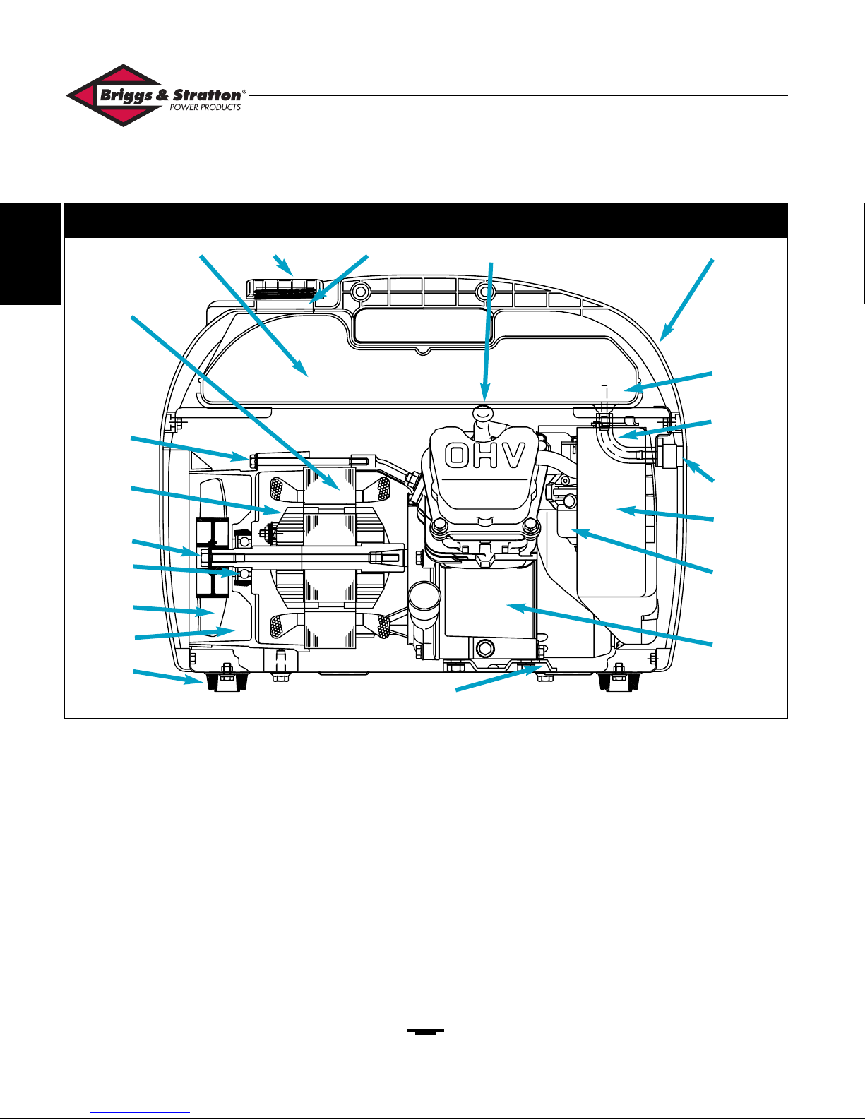
Item Nomenclature
1. Vibration Mount
2. Bearing Carrier
3. Cooling Fan
4. Rotor Bearing
5. Rotor Bolt (M6-160)
6. Rotor Assembly
7. Stator Bolt (M6-90)
8. Stator Assembly
9. Fuel Tank
10. Fuel Cap
Item Nomenclature
11. Fuel Inlet Filter
12. Spark Plug
13. Generator Case Half
14. Fuel Filter
15. Fuel Hose
16. Fuel Valve
17. Air Cleaner
18. Carburetor
19. Engine
20. Engine Base
GENERATOR DESCRIPTION
Introduction • Section 1
Hand-Held Series Generators • Familiarization & Troubleshooting Guide
Figure 1 — Internal Components
1
7
12 13
14
15
16
17
18
19
20
11
10
9
8
6
5
4
3
2
1
Page 13
9
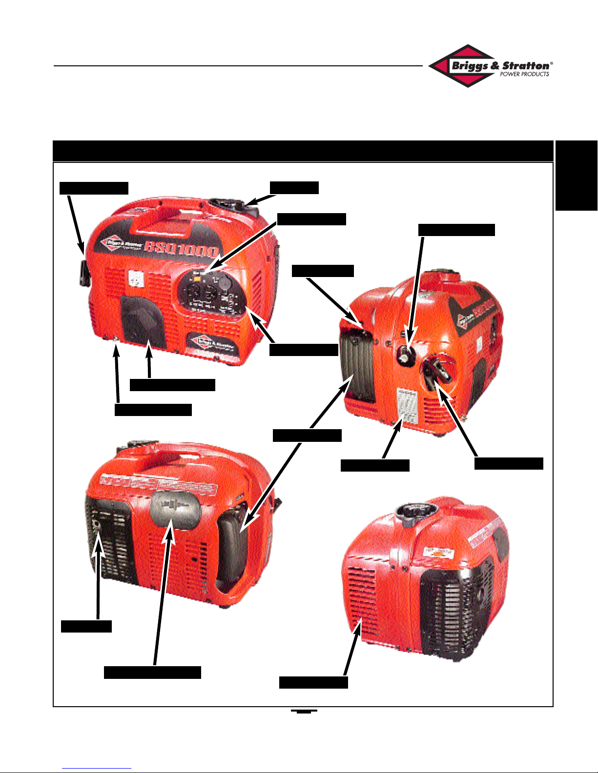
GENERATOR COMPONENTS
Section 1 • Introduction
Hand-Held Series Generators • Familiarization & Troubleshooting Guide
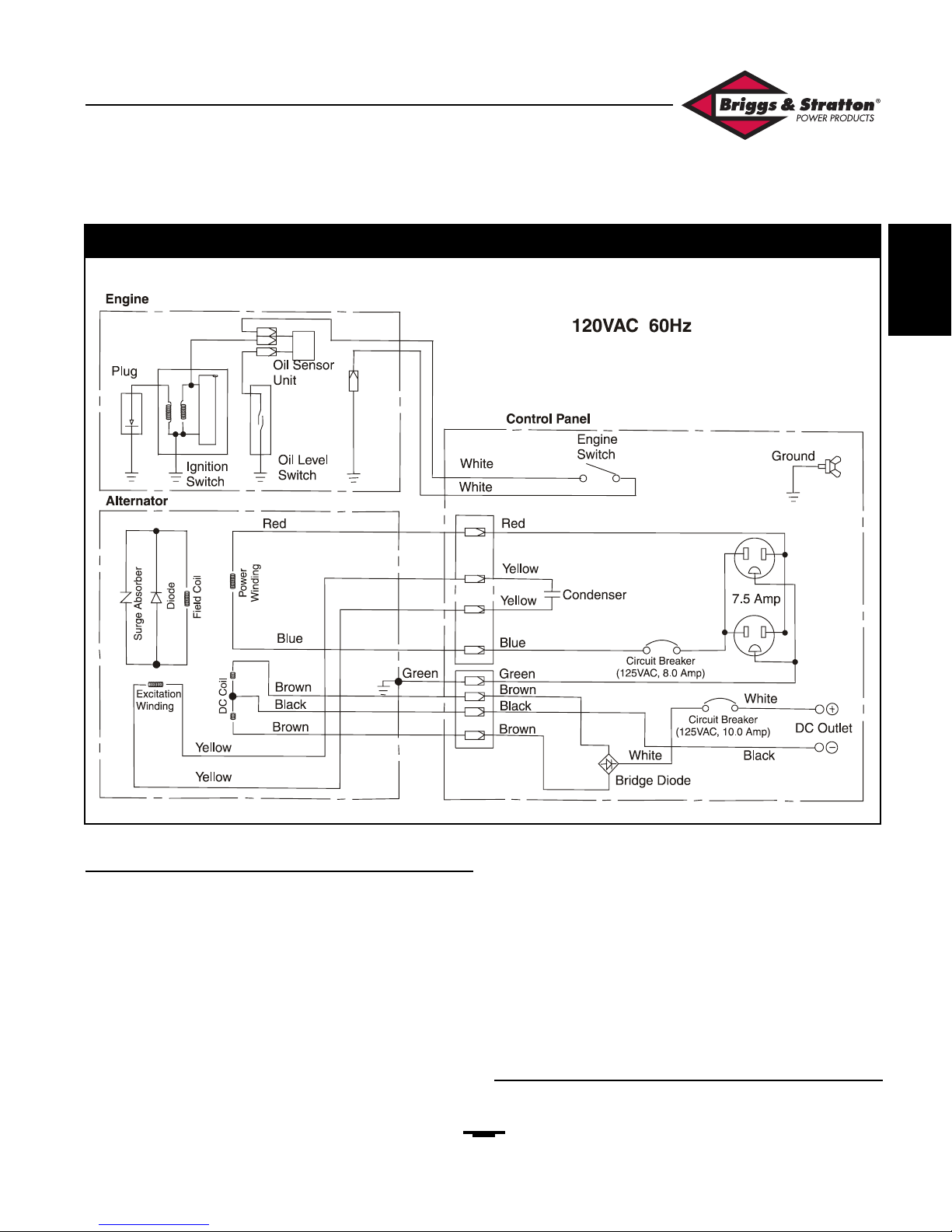
Figure 2 — External Components
Control Panel
Oil Service Cover
Grounding Lug
Muffler
Spark Plug Access
Recoil Starter
Recoil Starter
Engine Switch
Air Cleaner
Data Plate
Cooling Fan
Choke Lever
Fuel Shut-Off
Fuel Cap
1
Page 14
10
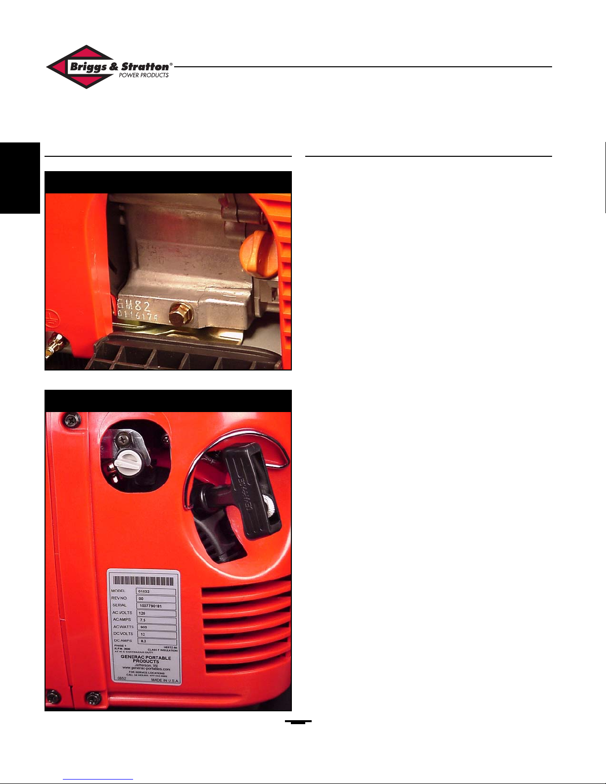
Serial Number Locations Generator Specifications
Engine:
Name: GM82 or Vanguard
Type: Air Cooled, Four
Cycle Gasoline
Engine
Displacement: 80 cubic centimeters
Max. Power: 1.8KW @ 4000RPM
Rated (AC) Power: 1.3KW @ 3000RPM
Oil Capacity: 0.4 Liter
Starting System: Recoil Starter
Oil Alert System: Yes
Generator: N. American Europe
(AC) Frequency: 60Hz
Phase: Single Single
(AC) Rated Voltage: 120 VAC 230VAC
(AC) Rated Current:: 7.5 Amps 3.2 Amps
(AC) Rated Output: 900 VA 750 VA
(AC) Maximum Output: 1000 VA 900 VA
(DC) Output: 12 VDC 12VDC
@ 8.3 Amps @ 8.3 Amps
Voltage Regulator: Condenser Condenser
Rated Power Factor: 1.0 1.0
Rated: Continuous Continuous
Other:
Fuel Capacity: 4.5 Liter / 1.18 Gal 4.5 Liter / 1.18 Gal.
Continuous Operation: 6.4 Hours 6.4 Hours
Noise Level: 63 DBA 63 DBA
@ 7 Meters @ 7 Meters
Dimensions: Length: 465mm 465mm
Width: 343mm 343mm
Height: 371mm 371mm
Dry Weight: 55 lbs. / 25 Kg 55lbs. / 25 Kg
Introduction • Section 1
Hand-Held Series Generators • Familiarization & Troubleshooting Guide
Figure 3 — Engine Serial Number Location
Figure 4 — Generator Serial Number Location
1
Page 15
11
Output Power (AC)
The residual magnetism of the rotor induces an (AC)
voltage in the power and excitation windings when the rotor
is turned by hand (when recoil starter is pulled). The (AC)
voltage of the excitation winding builds in the condenser
until it discharges. This "capacitive discharge" then
strengthens the magnetic field in the excitation winding. As
the rotor windings "cut" this strengthened magnetic field, a
higher (AC) voltage is induced in the rotor winding. The
diode in the rotor rectifies the induced rotor (AC) to (DC).
The intensified magnetic field of the rotor "cuts" across both
the power and excitation windings. When the engine starts
and spins the rotor, residual magnetism is overcome and this
cycle continues to increase the (AC) output voltage of the
power and excitation windings until magnetic saturation and
condenser capacity is balanced. This is the calculated "Rated
Output" of the generator.
When an external load is plugged into an output receptacle,
the increased current flow intensifies the magnetic field of
the power winding. As the magnetic field of the rotor "cuts"
across the intensified field of the power winding, an
additional voltage is induced into the rotor field winding.
This increases the output of the power winding to
compensate for the voltage drop of the load.
Output Power (DC)
(AC) voltages that are induced into the 12VAC winding are
rectified to (DC) by a "full-wave" bridge rectifier.
GENERATOR SYSTEMS
Section 1 • Introduction
Hand-Held Series Generators • Familiarization & Troubleshooting Guide
Figure 5 — Generator Wiring Diagram
1
Page 16

12
Fuel System Components
Fuel Group:
The components that make up the Fuel group include the
items listed in Figure 6.
The items listed in Figure 7 are part of the fuel cap and are
not replaceable. If damage occurs to the fuel cap, its repair is
limited to replacement.
GENERAL SERVICE INFORMATION
Work Area
Good lighting and an elevated table will help you gain access
to all of the mounting hardware and accessories of the handheld generator. Certainly, larger is better but a good
minimum sized table would be 20in. by 30in. If casters are
applied to the legs of the table, be sure they are secure and
sturdy enough to support not only the generator but also
the work being performed.
Hand Tools
A minimum collection of standard mechanic's hand tools
should include:
· 3/8" drive socket set (SAE)
· 3/8" drive socket set (Metric)
· A 3/8" drive ratchet
· Short, medium and long 3/8" drive extensions
· A large (heavy) "soft" mallet
· A common screwdriver (medium length)
· A Phillips screwdriver (medium length)
· A Phillips screwdriver (short- "stubby")
· A large (heavy duty) screwdriver suitable for mild prying
Special Tools
Electronic Measuring Equipment:
The measuring equipment used in troubleshooting should be
of industrial quality and have the sensitivity to measure
electronic values to the third decimal. Its accuracy should be
within acceptable tolerances should have the ability to
measure capacitance.
Introduction • Section 1
Hand-Held Series Generators • Familiarization & Troubleshooting Guide
Figure 6 — Fuel Systems Components
Shut-Off Valve
Fuel Hose
Fuel Cap Assembly
Fuel Strainer
Spill Well
Tank
Mounting Brackets
Tank Sump Filter
Figure 7 — Fuel Cap Assembly
1
Page 17

13
Section 2 • Disassembly
Hand-Held Series Generators • Familiarization & Troubleshooting Guide
DISASSEMBLY
2
Page 18

14
Disassembly • Section 2
Hand-Held Series Generators • Familiarization & Troubleshooting Guide
2
Page 19

15
General Disassembly Considerations
Always inspect the external condition of the plastic
components before disassembling the unit. Look for cracks
and broken plastic and be sure to note these conditions as
existing before maintenance is undertaken.
Hand-held generators are built to close tolerances. The
fasteners used to hold the plastic shrouds and covers are
special machine screws that have a "pilot" collar
incorporated into the grip area of the screw (Figure 8).
NOTE: When assembling plastic components, be
sure the "collar" of the screw fits into the opening of
the shroud or cover. Pinching the plastic under the
collar will break the plastic at the mounting locations.
The length of these fasteners is critical to the proper
assembly of the unit. When disassembling the generator, it is
recommended that the location and length of each fastener
be noted.
When troubleshooting becomes necessary, access to various
components, systems and structural members is required.
Regardless of the ultimate reason, a clear understanding of
the unit's disassembly will save time and effort.
NOTE: Do not attempt to remove the protective
grill that surrounds the exhaust muffler. The fasteners
that hold it in place are secured with plain nuts and
lock-washers. If you attempt to remove the grill, it
will be necessary to disassemble the case halves in
order to reinstall it properly.
Case Separation
• Remove the cover to the air cleaner.
• Set the air filter and support grill aside.
• Remove the two mounting nuts that hold the air filter
assembly to the carburetor (Figure 48, Pg. 34).
• Remove the two screws that hold the handle of the
unit together (Figure 9).
At this point, position the unit so you are facing the muffler
side of the generator.
• Remove only those fasteners that hold the rear case
half. That is:
• Those screws around the lower base of the rear
of the generator.
• The upper screws that secure the rear case-half
on the right and left side of the generator.
• Grasp the rear case half and gently separate it from the
generator unit.
Section 2 • Disassembly
Hand-Held Series Generators • Familiarization & Troubleshooting Guide
Figure 8 — Screws with ”Pilot Collar”
Pilot Collars
Figure 9 — Remove Screws In Handle
2
Page 20

16
• Remove the screw that is next to the fuel shut-off valve
and retain the mounting bracket that supports the fuel
tank (Figure 10).
• Slide the fuel tank out of its cradle and remove the fuel
supply hose from the bottom of the tank (Figure 11).
Disassembly • Section 2
Hand-Held Series Generators • Familiarization & Troubleshooting Guide
Figure 10 — Mounting Bracket Screw
Figure 11 — Remove Fuel Supply Hose
Hose to Tank
2
Page 21

17
NOTE: At this point, you have visual access to
many of the mechanical and electronic components of
the generator (Figure 12).
Many individual electronic components are supported by
clips and brackets that are molded parts of the front case
half. This disassembly procedure assumes you are seeking
access to the engine and generator for overhaul purposes
and the components that are held by the case will be left in
their mountings.
• Position the unit so you are facing the front of the
generator.
• Remove the screws around the base.
• Separate the electrical connectors at locations shown in
Figures 13A and 13B.
• Set the front case-half aside.
ACCESS TO GENERATOR COMPONENTS
Section 2 • Disassembly
Hand-Held Series Generators • Familiarization & Troubleshooting Guide
Figure 12 — Access To Generator Components
Figure 13 — Generator Components
A
B
Harness Connectors
2
Page 22

18
This provides sufficient access to the generator unit for
troubleshooting, component replacement and overhaul
(Figure 14).
A view of the electrical components that are mounted on
the inside of the front case-half is provided in Figure 15.
Rotor / Stator Removal
•• Step 1:
• For easier access, position the unit as shown in
figure 16.
•• Step 2:
Remove the cooling fan as shown. (Figure 17).
NOTE: Mark the face of the fan to ensure proper
reassembly.
Disassembly • Section 2
Hand-Held Series Generators • Familiarization & Troubleshooting Guide
Figure 14 — Generator Unit Exposed
Figure 15 — Electrical Components Mounted On Case
Figure 16 — Position For Rotor Removal / Inspection
Figure 17 — Remove Cooling Fan
2
Page 23

19
•• Step 3:
• Remove the heat shield mounting screws (Figure 18A).
•• Step 4:
• Remove the rear bearing carrier mount bolts
(Figure 18B).
•• Step 5:
• Remove the three through-bolts (Figure 19).
•• Step 6:
• Remove the rear bearing carrier and the stator
together (Figure 20).
Disassembly • Section 2
Hand-Held Series Generators • Familiarization & Troubleshooting Guide
Figure 18 — Hardware (Heat Shield / Stator Housing)
Figure 19 — Remove Stator Through-Bolts
A
B
Figure 20 — Remove Stator Housing & Stator
2
Page 24

20
Disassembly • Section 2
Hand-Held Series Generators • Familiarization & Troubleshooting Guide
2
Page 25

21
Section 3 • Troubleshooting
Hand-Held Series Generators • Familiarization & Troubleshooting Guide
TROUBLESHOOTING
3
Page 26

22
Troubleshooting • Section 3
Hand-Held Series Generators • Familiarization & Troubleshooting Guide
Under Voltage (DC)
Refer to Figure 21 ("Under Voltage (DC)" Flow Chart)
above for the sequential steps involved with this procedure.
To separate the case halves, see page 13.
Test A: - Check Engine RPM
(See Appendix)
Test B: - Check Receptacle Wiring
(Page 25)
Figure 21 —
Under-Voltage (DC)
Troubleshooting Flow Chart
Test A
Check Engine RPM
See Appendix
OK?
Repair/Replace
See B&S #272147
NO
DC
OK?
YES
YES
NO
Test B
Check
Receptacle
Wiring
OK
?
Repair/Replace
See Page 25
NO
DC
OK?
YES
YES
NO
Test C
Check DC
Circuit
Breaker
OK?
Repair/Replace
See Page 21
NO
DC
OK?
YES
YES
NO
Test D
Check Bridge
Diode
OK?
Repair/Replace
See Page 21
NO
DC
OK?
YES
YES
NO
Test E
Check 12VDC
Coil
OK?
Repair/Replace
See Page 21
NO
DC
OK?
YES
YES
NO
Test F
Check Rotor
Winding
OK
?
Repair/Replace
See Page 27
NO
DC
OK?
YES
YES
NO
END
3
Page 27

23
Hand-Held Series Generators • Familiarization & Troubleshooting Guide
Section 3 • Troubleshooting
Test C: - Check (DC) Circuit Breaker
•• Step 1:
• Remove the three screws that secure the control panel
to the face of the generator unit.
•• Step 2:
• Remove both the terminals at the back of the circuit
breaker (Figure 22A).
•• Step 3:
• With the circuit breaker ON and your VOM set to
ohms, check for continuity at the terminals of the
circuit breaker (Figure 22B).
- Continuity = Circuit Breaker OK
- No Continuity = Defective Circuit Breaker.
Replace Circuit Breaker
Test D: - Check Bridge Diode
With the control panel still removed:
•• Step 1:
• Locate and separate the harness connector that has the
two brown wires. Push the male half of the connector
aside.
NOTE: You must follow the Diode Test
instructions that are provided with the meter you are
using.
•• Step 2:
• Using the female terminals of the brown wires and the
positive output terminal of the cigarette lighter, or the
DC receptacle, you can check continuity of the bridge
diode wiring (Figure 23).
Test E: - Check 12VDC Coil
With the control panel still removed:
•• Step 1:
• Locate and separate the harness connector that has the
two brown wires coming.from the stator.
•• Step 2:
• With your VOM set to ohms, read the coil resistance
at the terminal of the brown leads in the connector
(Figure 24).
•• Step 3:
• Compare readings with resistance values in the
apppendix.
Test F: - Check Rotor Winding
(See Test G on Page 27)
Figure 22 — Checking (DC) Circuit Breaker
Figure 23 — Checking The Bridge Diode
Yes Yes Yes
(+) ~1 ~2 (-)
~1 No No Yes
~2 No No Yes
(-) No No No
Negative Probe (-)
Positive Probe (+)
(+)
Figure 24 — Reading 12VDC Coil Resistance
A
B
Brown
3
Page 28

Hand-Held Series Generators • Familiarization & Troubleshooting Guide
"Over Voltage" (AC)
Refer to Figure 25 ("Over Voltage (AC)" Flow Chart) above
for the sequential steps involved with this procedure. To
separate the case halves, see page 13.
Test A: - Check Engine RPM
(See Appendix)
Test B: - Check Capacitor
The capacitor can be checked without disassembling the unit
case-halves.
•• Step 1:
• Remove the three screws that secure the control panel
to the face of the generator unit (Figure 26).
•• Step 2:
• Disconnect the harness connector that has the two
yellow wires.
•• Step 3:
• Using a jumper wire, (Figure 27) short the two yellow
terminals that come from the capacitor. Then remove
the jumper wire.
24
Section 3 • Troubleshooting
Figure 25 —
Over-Voltage (AC)
Troubleshooting Flow Chart
Figure 26 — Remove Control Panel
Test A
Check Engine RPM
See Appendix
OK
?
Test B
Check
Capacitor
Repair/Replace
See Page 22
OK?
AC
OK?
AC
OK?
END
Repair/Replace
See B&S #272147
YES
YES
YES
YES
NO
NO
NO
NO
3
Page 29

25
Section 3 • Troubleshooting
Hand-Held Series Generators • Familiarization & Troubleshooting Guide
•• Step 4:
• Refer to the owner's manual of your VOM and test the
capacitor according to the directions for your
equipment.
• Find the rating of the capacitor on its body or in the
appendix of this manual.
• Compare reading with the stated value .
Replace the capacitor if it is found to be faulty.
Figure 27 — Short the Capacitor Terminals
Figure 28 — Testing the Capcitor
Yellow
3
Page 30

26
Hand-Held Series Generators • Familiarization & Troubleshooting Guide
Troubleshooting • Section 3
Figure 29 —
Under-Voltage (AC)
Troubleshooting Flow Chart
Test A
Check Engine RPM
See Appendix
OK?
Repair/Replace
See B&S #272147
NO
AC
OK?
YES
YES
NO
Test B
Check
Receptacle
Wiring
OK?
Repair/Replace
See Page 25
NO
AC
OK?
YES
YES
NO
Test C
Check AC
Circuit
Breaker
OK?
Repair/Replace
See Page 25
NO
AC
OK?
YES
YES
NO
Test D
Check Stator
Power
Winding
OK?
Repair/Replace
See Page 26
NO
AC
OK?
YES
YES
NO
Test E
Check
Capacitor
OK?
Repair/Replace
See Page 22
NO
AC
OK?
YES
YES
NO
Test F
Check
Excitation
Winding
OK?
Repair/Replace
See Page 26
NO
AC
OK?
YES
YES
NO
Test G
Check Rotor
Winding
OK
?
Repair/Replace
See Page 27
NO
AC
OK?
YES
YES
NO
END
3
Page 31

Section 3 • Troubleshooting
Hand-Held Series Generators • Familiarization & Troubleshooting Guide
27
Under Voltage (AC)
Refer to Figure 29 ("Under Voltage (AC)" Flow Chart) on
the preceding page for the sequential steps involved with
this procedure. To separate the case halves, see page 13.
Test A: - Check Engine RPM
(See Appendix)
Test B: - Check Receptacle Wiring
•• Step 1:
• Remove the three screws that secure the control panel
to the face of the generator unit.
•• Step 2:
• Test the receptacle for:
- Shorted contacts.
- Burned or cracked insulation material.
- Faulty terminal screws (Figure 30).
•• Step 3:
• If any faults are found,
- Replace receptacle.
Test C: - Check AC Circuit Breaker
•• Step 1:
Remove both the terminals at the back of the circuit
breaker (Figure 31A).
•• Step 2:
• With the circuit breaker CLOSED and your VOM set
to ohms, check for continuity at the terminals of the
circuit breaker (Figure 31B).
- Continuity: = Circuit Breaker - OK
- No Continuity: = Defective Circuit Breaker.
Replace Circuit Breaker
Figure 30 — AC Receptacle
Figure 31 — Checking Circuit Breaker
3
Page 32

28
Hand-Held Series Generators • Familiarization & Troubleshooting Guide
Troubleshooting • Section 3
Test D: - Check Stator Power Winding
•• Step 1:
• Disconnect the 4-pin harness connector that contains
the yellow wires.
•• Step 2:
• On the male portion of the connector, locate the pins
that connect the blue and red wires (This harness
should be coming from the generator stator assembly
see figure 32).
•• Step 3:
• With your VOM set to ohms, measure the resistance
across the blue and red wires that come from the
stator (Figure 32).
• Compare reading with the resistance values in the
appendix.
- Within tolerance: Power winding is good
- Exceeds tolerance: Replace Stator
Test E: - Check Capacitor
(Page 22)
Test F: - Check Excitation Winding
•• Step 1:
• Disconnect the harness connector that contains the
yellow wires.
•• Step 2:
• On the male portion of the connector, find the pins
that connect the two yellow wires (This harness should
be coming from the generator stator assembly see
figure 33).
•• Step 3:
• With your VOM set to ohms, measure the resistance
across the two yellow wires that come from the stator
(Figure 33).
• Compare reading with the resistance values in the
appendix.
- Within tolerance: Excitation winding is good
- Exceeds tolerance: Replace Stator
Figure 33 — Checking Excitation Winding
Figure 32 — Checking Stator Power Winding
3
Page 33

29
Section 3 • Troubleshooting
Hand-Held Series Generators • Familiarization & Troubleshooting Guide
Test G: - Check Rotor Winding
The rotor is considered a non-serviceable part because it is
a sealed unit that would require disassembly to properly
test. Therefore, it is by process of eliminating all other
possible faults that the rotor can be considered faulty.
NOTE: Piercing the red or blue wire and checking
across the terminal post of the rotor diode is not
recommended.
Before rotor replacement, follow the checklist outlined
below:
• Check Engine RPM
• Check Capacitor
• Check Output Receptacle & Wiring
• Check Circuit Breaker (AC)
• Check Circuit Breaker (DC)
• Check Stator Power Winding
• Check Excitation Winding
• Check Bridge Diode
• Check 12VDC Coil
Engine Switch
•• Step 1:
• Remove the three screws that secure the control panel
to the face of the generator unit.
•• Step 2:
• Remove the terminals from the switch.
•• Step 3:
• With your VOM set to ohms, cycle the switch to ON
and test for continuity (Figure 34).
- You should have continuity.
•• Step 4:
• Cycle the switch to OFF.
- You should not have continuity.
Figure 34 — Checking The Engine Switch
3
Page 34

30
Troubleshooting • Section 3
Hand-Held Series Generators • Familiarization & Troubleshooting Guide
Pilot Lamp
Some early units were equipped with a green pilot lamp. If
this is the case, troubleshoot the lamp using the instructions
that follow;
•• Step 1:
• Remove the three screws that secure the control panel
to the face of the generator unit.
•• Step 2:
• Remove the terminals from the lamp.
•• Step 3:
• With your VOM set to ohms, check for continuity
through the lamp (Figure 35).
- No continuity: Replace lamp.
Figure 35 — Checking The Pilot Lamp
3
Page 35

31
Section 4 • Assembly
Hand-Held Series Generators • Familiarization & Troubleshooting Guide
ASSEMBLY
4
Page 36

32
Assembly • Section 4
Hand-Held Series Generators • Familiarization & Troubleshooting Guide
4
Page 37

33
Section 4 • Assembly
Hand-Held Series Generators • Familiarization & Troubleshooting Guide
Mounting The Rotor & Stator
Position the generator/base plate assembly as shown in
figure 36, before mounting the stator assembly.
• Mount the rotor on the tapered shaft of the engine
(Figure 37).
NOTE: The rotor is not timed in any way.
• Position the stator and the rear bearing carrier over
the rotor and align the feet with the mounting holes in
the base plate (Figure 38).
• Install the bolts but do not tighten yet.
Make sure the stator is seated in the machined lands of its
cradle as shown in figure 39A and 39B.
With the stator properly seated in the machined lands of its
cradle:
Figure 36 — Generator / Base Plate Assembly
Figure 37 — Mount The Rotor
Figure 38 — Positioning The Stator
Figure 39 — Seating The Statot Assembly
4
A
B
Page 38

34
Assembly • Section 4
Hand-Held Series Generators • Familiarization & Troubleshooting Guide
• Install the three stator through-bolts and tighten until
the rear bearing carrier is secure (Figure 40).
• Check to make sure there are no obstructions to the
rotation of the rotor assembly.
• Torque the through bolts to 85 lbs. in.
• Torque the mounting bolts in the feet of the rear
bearing carrier to 180 lbs. in.
• Slip the rotor mount bolt through the cooling fan. Start
the bolt in the threads of the engine output shaft by
hand (Figure 41).
Before tightening the rotor mount bolt:
• Check the orientation of the fan (Figure 42).
Torque the rotor mount bolt to 100 lbs. in.
Install The Muffler Heat Shield
• Slip the heat shield between the muffler and the
generator until the mounting flanges of the rear bearing
carrier align with the mounting flange of the heat shield
(Figure 43A & 43B).
Figure 40 — Securing The Stator Assembly
Figure 41 — Installing Rotor Mount Bolt
Figure 42 — Cooling Fan Orientation
Figure 43 — Generator Heat Shield
A
B
4
Page 39

35
Hand-Held Series Generators • Familiarization & Troubleshooting Guide
• Install the mounting screws and tighten until the heat
shield is secure.
NOTE: Make sure that the bent angles of the heat
shield are in contact with surfaces of the engine as
shown in figure 44.
Check to make sure that all the mounting hardware is tight
and secure.
Connecting The Wiring Harness
The control panel that is mounted in the front case half is
connected to the generator by means of two four-pin cable
connectors. The associated wires colors are identical.
• Match the wire colors of the two harness connectors
and seat each connector until it locks into place
(Figure 45).
• Connect one lead of the engine run switch to the
engine ground wire.
• Connect the other wire from the engine run switch to
the connector that also houses the blue wire from the
ignition coil (Figure 46).
Figure 44 — Check Heat Shield Contact And Mounting
Figure 45 — Harness Connectors
Section 4 • Assembly
Figure 46 — Ground And Run Switch
4
Page 40

36
Hand-Held Series Generators • Familiarization & Troubleshooting Guide
Mount The Rear Case Halve
• Position the unit as shown in figure 47.
• Mount the air cleaner housing to the two studs that
extend through the carburetor (Figure 48A).
• Insert the oil breather hose into the back of the air cleaner
housing (Figure 48B).
NOTE: Make sure that the steel bushings are
installed in the housing for the air cleaner
(Figure 48A).
The rear case half is mounted on the carriage first.
• Align the rear case half with the mounting holes in the
generator carriage.
• Refer to figure 49A & B and place the fasteners as shown.
The tank support brackets are shown in figure 50A & B.
• Insert the left-hand tank support bracket inside the case
stiffener and secure to the rear case half with a M5-16
screw with a medium pilot collar (Figure 50A).
• Mount the right hand bracket as shown in figure 50B.
Assembly • Section 4
Figure 47 — Unit Positioned For Closure
Figure 48 — Breather Tube & Air Filter Housing
Figure 49 — Rear Case Half Fasteners
A
B
M6-16
M6-20
M6-20
A
B
Figure 50 — Fuel Tank Support Brackets
A
B
M5-16
4
Page 41

Hand-Held Series Generators • Familiarization & Troubleshooting Guide
37
Mount The Fuel Tank
Inspect the tank for the following items;
• Ensure that the fuel strainer is installed in the bottom of
the tank sump.
• Check that the rubber vibration seals are glued on the
seams of the fuel tank.
• Seat the tank in the area above the support brackets
(Figure 51).
• Connect the fuel supply hose to the tank as shown in
figure 52.
Mount The Front Case Half
Before mounting the front case half, ensure that the LOS
module is oriented on its mounting as shown in figure 53.
• Position the front case half close enough to the generator
unit in order to make the wiring connections to the Low
Oil Sense (LOS) module and start switch (Figure 54).
Section 4 • Assembly
Figure 51 — Mounting The Fuel Tank
Figure 52 — Connecting The Fuel Supply Hose
Figure 53 — LOS Orientation
Figure 54 — Start Switch & (LOS) Wiring
4
Page 42

38
Hand-Held Series Generators • Familiarization & Troubleshooting Guide
• Route the starter rope through its opening in the case.
• Align the front case half with the mounting points in the
generator carriage and install the fasteners (figure 55).
With the mounting fasteners tight, connect the wiring
harness connectors through the opening of the control
panel (Figure 56).
• Match the colors of the wires.
NOTE: Match the color-coding of the wires to
make sure that you are making the proper
connections (Figure 57).
• Install the control panel face plate (Figure 58).
• Install oil service cover (Figure 59).
Assembly • Section 4
Figure 55 — Fastener Locations On Front Case Half
Figure 56 — Access To Wiring Harness
Figure 57 — Wiring Harness Connections
Figure 58 — Install Control Panel
4
Page 43

39
Hand-Held Series Generators • Familiarization & Troubleshooting Guide
• Install air filter assembly (Figure 60).
• Install fuel spill well and fuel cap (Figure 61).
Section 4 • Assembly
Figure 59 — Install Oil Service Door
Figure 61 — Install Spill Well & Fuel Cap
Figure 60 — Install Air Filter Assembly
4
Page 44

40
Hand-Held Series Generators • Familiarization & Troubleshooting Guide
Assembly • Section 4
4
Page 45

41
Section 5 • Appendix
Hand-Held Series Generators • Familiarization & Troubleshooting Guide
APPENDIX
5
Page 46

42
Appendix • Section 5
Hand-Held Series Generators • Familiarization & Troubleshooting Guide
5
Page 47

43
Resistance Values
Rotors:
(60HZ) 4.06 ohm
(50HZ) 4.10 ohm
Stators:
(60HZ)
Excitation Winding 3.911 ohm
Power Winding 1.010 ohm
12VDC Winding .429 ohm
(50HZ)
Excitation Winding 4.79 ohm
Power Winding 4.33 ohm
12VDC Winding .510 ohm
Capacitors:
(60HZ) 14 µFu
(50HZ) 14 µFu
APPENDIX
Hand-Held Series Generators • Familiarization & Troubleshooting Guide
Section 5 • Appendix
Torque Specifications
Engine:
Item Size Torque Value
(In. Lbs.)
Connecting Rod M6x30 85
Crankcase Cover M6x12 85
M8 180
Muffler M8 180
Head Bolt M8x55 220
Flywheel Nut M12 400
Spark Plug M14 180
Oil Drain Plug M10 180
Cooling Fan 5/16" 85
Pivot Bolt M8 180
General Screws M5 35
Rocker Arm Assy. M6x16 45
M8 180
CT Bolt M6 85
M8 180
Rocker Box Cover M6x12 45
Generator:
Rotor Bolt M6 100
Stator Bolt M6 85
Tapping Screw M6 45
General Screws M4 20
M5 35
M6 45
M8 180
5
Page 48

44
M6-16
M6-20
M6-20
M5-10
M5-10
M5-16
M5-16
M6-16
M6-16
M6-16
Appendix • Section 5
Hand-Held Series Generators • Familiarization & Troubleshooting Guide
5
Figure 62 — Fastener Sizes and Locations
Page 49

45
Section 5 • Appendix
Hand-Held Series Generators • Familiarization & Troubleshooting Guide
M6-90
M8-12
M8-12
M8
Self-Tapping Screw
M8-12
M6-160
5
Figure 63 — Fastener Sizes and Locations (Continued)
Page 50

46
Appendix • Section 5
Hand-Held Series Generators • Familiarization & Troubleshooting Guide
5
 Loading...