

Page 1

MODEL
BP33-W / BP43-W
BRUSH CUTTER OPERATOR’ S MANUAL
©2010.
Briggs & Stratton Power Products Group, LLC.
All Rights Reserved.
Page 2

2
Trimmer / Brushcutter
Model Number
Revision
Serial Number
Date Purchased
Thank You for purchasing this quality-built Briggs & Stratton Trimmer/Brushcutter. We’re
pleased that you placed your confi dence in our brand. When operated and maintained according to the instructions in this manual, your Briggs & Stratton Trimmer/Brushcutter will provide
dependable service.
This manual contains safety information to make you aware of the hazards and risks associated
with the machine and how to avoid them. This machine is intended for trimming and brushcutting
and is not intended for any other purpose. It is important that you read and understand these
instructions thoroughly before attempting to start or operate this equipment. Save these original
instructions for future reference.
The trimmer/brushcutter requires fi nal assembly before use. Refer to the Assembly section of
this manual for instructions on fi nal assembly procedures. Follow the instructions completely.
Where to Find Us For quality support and service for your Briggs & Stratton
Trimmer/Brushcutter. Contact your local distributor. To obtain an Illustrated Parts List for your
product, please visit our website, BRIGGSandSTRATTON.com.
Page 3

3
TABLE OF CONTENTS
4
9
11
11
11
12
13
13
14
14
14
16
16
17
17
17
18
18
18
19
19
20
20
21
22
22
22
23
23
25
26
OPERATOR SAFETY
FEA TURES AND CONTROLS
ASSEMBLY
Install Trimmer Head to the Cutting Head
Install Trimmer Head Guard
Install Trimmer Head Line
Install Brushcutter Blade to the Cutting Head
Install Handle
OPERATION
Fuel Recommendations
How to Add Fuel
Starting the Engine
Stopping the Engine
Operating Position
Using Nylon Trimmer Line
Using Brushcutter Blade
Blade Thrust
Trimming and Edging
Operating on Slopes
MAINTENANCE
Maintenance Schedule
Spark Plug Maintenance
Air Filter Maintenance
Cutting Attachment Maintenance
STORAGE
Protect Fuel System
Clean the Unit
Storage Safety
TROUBLESHOOTING
WARRANTY
SPECIFICATIONS
Page 4
4
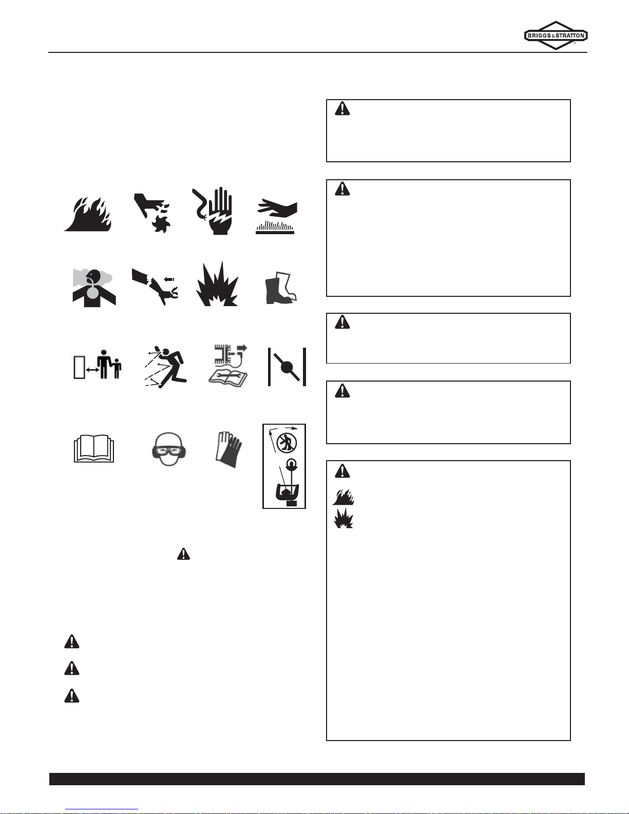
FIRE
MOVING PARTS SHOCK
SAFETY
GOGGLES,
& EAR
PROTECTION
TOXIC FUMES KICKBACK EXPLOSION
HOT SURFACE
READ MANUAL
STURDY
FOOTWEAR
CHOKE
Safety Symbols and Meanings
OPERATOR SAFETY
THROWN
OBJECTS
SAFE DISTANCE
SAFETY
GLOVES
REMOVE
SPARK PLUG
360
15 meters (50 feet)
SAFE
DISTANCE
SAVE THESE INSTRUCTIONS - This manual contains
important instructions that should be followed during the
initial set-up, the operation, and the maintenance of the
equipment.
The safety alert symbol is used to identify safety
information about hazards that can result in personal
injury. A signal word (DANGER, WARNING, or CAUTION) is used with the alert symbol to indicate the likelihood and the potential severity of injury. In addition, a
hazard symbol may be used to represent the type of
hazard.
DANGER indicates a hazard which, if not avoided,
will result in death or serious injury.
WARNING indicates a hazard which, if not avoided,
could result in death or serious injury.
CAUTION indicates a hazard which, if not avoided,
could result in minor or moderate injury.
NOTICE indicates a situation that could result in
damage to the product.
WARNING Read understand and follow all the
instructions on the trimmer and in this manual
before operating the unit. Failure to observe the
safety instructions in this manual will result in death
or serious injury.
WARNING The engine exhaust from this product contains chemicals known to the State of California to cause cancer , birth defects, or other reproductive harm.
WARNING Certain components in this product
and its related accessories contain chemicals
known to the State of California to cause cancer,
birth defects, or other reproductive harm. Wash
hands after handling.
WARNING Gasoline and its vapors are extremely
fl ammable and explosive.
Fire or explosion can cause severe burns or death.
When Adding Fuel
• Fill fuel tank outdoors or in well-ventilated area.
• Check fuel lines, tank, cap, and fittings frequently
for cracks or leaks. Replace if necessary.
When Starting Engine
• Ensure that spark plug, muffler, and air cleaner (if
equipped) are in place and secured.
• Do not crank engine with spark plug removed.
When Operating Equipment
• Never start or run the engine with the air cleaner
assembly or the air filter removed.
When Transporting Equipment
• Transport with the fuel tank empty.
When Storing Fuel or Equipment With Fuel in Tank
• Store away from furnaces, stoves, water heaters
or other appliances that have pilot lights or other
ignition sources because they can ignite fuel vapors.
WARNING This cutting machine is capable of
amputating hands and feet and throwing objects
that can cause injury and damage! Failure to comply
with the following SAFETY instructions could result
in death or serious injury to the operator or bystanders. The operator must understand these instructions. The operator must be of sound mind and body
and must not be under the infl uence of any
substance that might impair vision, dexterity or judgment.
Page 5

5
360
15 meters (50 feet)
OPERATOR SAFETY
WARNING Thrown debris could cause eye
injuries. Noise levels could cause hearing
damage. Nylon trimming line and blades can
cut through clothes and skin.
• NEVER operate unit without protective guards in
place.
• DO NOT wear loose clothing, jewelry or anything
that could be caught in the starter or other rotating
parts.
• Keep hands and feet away from rotating parts.
• Wear safety goggles that meet ANSI standards
whenever you use the trimmer.
• Wear hearing protectors.
• Wear protective clothing to reduce the risk and severity
of injury. Wear trimmer harness, gloves, a longsleeved shirt, long pants, and sturdy boots with
nonslip soles.
WARNING Running engine gives off carbon
monoxide, an odorless, colorless, poison gas.
Breathing carbon monoxide can cause headache,
fatigue, dizziness, vomiting, confusion, seizures,
nausea, fainting or death.
• Operate equipment ONLY outdoors.
• Keep exhaust gas from entering a confined area
through windows, doors, ventilation intakes, or
other openings.
WARNING Exhaust heat/gases could ignite
combustibles or structures resulting in death,
serious injury or property damage. Contact with
the muffl er area could cause burns resulting in
serious injury.
• DO NOT touch hot parts.
• Allow equipment to cool before touching.
• It is a violation of California Public Resource Code,
Section 4442, to use or operate the engine on any
forest-covered, brush-covered, or grass-covered
land unless the exhaust system is equipped with a
spark arrester, as defined in Section 4442, maintained in effective working order. Other states or
jurisdictions may have similar laws. Contact the
original equipment manufacturer, retailer, or
dealer to obtain a spark arrester designed for the
exhaust system installed on the engine.
WARNING Rapid retraction of starter cord
(kickback) will pull hand and arm toward engine
faster than you can let go. Broken bones,
fractures, bruises, or sprains could result.
• When starting engine, pull the starter cord slowly
until resistance is felt and then pull rapidly to avoid
kickback.
• Blade or trimmer head must be securely attached.
WARNING Improperly maintaining the trimmer,
or failure to correct a problem before operation, can
cause a malfunction in which you can be seriously
hurt or killed. Always follow the inspection and maintenance recommendations and schedules in this
manual.
WARNING Moving parts could crush and
cut. Starter and other rotating parts could
entangle hands, hair, clothing, or accessories
resulting in serious injury.
• NEVER operate unit without protective guards in place.
• DO NOT wear loose clothing, jewelry or anything
that could be caught in the starter or other rotating
parts.
• Tie up long hair.
• Keep hands and feet away from rotating parts.
WARNING Objects thrown by the trimmer
can cause serious injury.
• Clear the area to be cut before each use. Remove
all objects such as broken glass, nails, wires, or
string, which could be thrown or become
entangled in the cutting attachment.
• Clear the area of children, bystanders, and pets.
• Keep all children, bystanders outside of a 50 ft (15 m)
radius.
• Bystanders should be encouraged to wear eye
protection.
WARNING
Unintentional sparking can resul t in fire or electric
shock.
Unintentionalstart-up can result in entanglement,
traumatic amputation, or laceration.
Fire hazard.
Before performing adjustments or repairs:
• Disconnect the spark plug wire and keep it away
from the spark plug.
• Use only correct tools.
• Replacement parts must be of the same design and
installed in the same position as the original parts.
Page 6

6
OPERATOR SAFETY
Trimmer Safety
• Read, understand, and follow instructions and warnings
in this manual and on the machine, engine and
attachments.
• Know the controls and the proper use of the machine
before starting.
• The equipment should only be used in good weather
conditions and with clear visibility.
• To prevent injury to others, keep people at least 50
feet (15 meters) away from the working area during
operation.
• DO NOT touch the cutting head or blade in motion.
• Keep fi rm footing and balance. Do not over-reach.
Keep cutting attachment below waist level. Keep all
parts of your body away from the rotating cutting
attachment and hot surfaces.
• NEVER use the unit without the blade guard securely
in place.
• Do not strike objects that may cause harm or damage
to the unit.
• Always wear eye protection and protective clothing.
Always wear the safety glasses provided with the
unit. Protect yourself when operating unit by wearing
safety glasses, a dust mask, long pants, ear protection, and substantial footwear.
• Clear the working area. Objects thrown by the trimmer
can cause serious injury. Before operating the
trimmer, carefully inspect the area and remove any
broken glass, pieces of wire, and other loose objects.
• The cutting attachment may be spinning during
carburetor adjustments. Wear protective equipment
and observe all safety instructions. For units
equipped with a clutch, be sure the cutting attachment stops turning when the engine idles. When the
unit is turned off, make sure the attachment has
stopped before the unit is set down.
• A coasting blade can cause injury while it continues
to spin after the engine is stopped or throttle trigger is
released. Maintain proper control until the blade has
completely stopped rotating.
Protection for Children, Bystander, and Pets
Tragic accidents can occur if the operator is not alert to
the presence of children, bystanders, and pets. Children
are often attracted to the machine and the trimming
activity. Never assume that children will remain where
you last saw them.
• Keep children out of the trimming area and under the
watchful care of a responsible adult.
• Clear the area to be cut before each use. Remove all
objects such as broken glass, nails, wires, or string,
which could be thrown or become entangled in the
cutting attachment.
• Clear the area of children, bystanders, and pets.
• Keep all children, bystanders outside of a 50 ft (15 m)
radius.
• Bystanders should be encouraged to wear eye protection.
• Do not allow children or others to use the equipment
or attachments. They can be seriously injured.
• Allow only responsible persons who understand these
instructions to operate this equipment.
• Use extra care when approaching blind corners, shrubs,
trees, or other objects that may obscure vision.
Safe Handling of Gasoline
To avoid personal injury or property damage, use
extreme care in handling gasoline. Gasoline is extremely
flammable and the vapors are explosive.
• Extinguish all cigarettes, cigars, pipes and other sources
of ignition.
• Use only an approved fuel container.
• DO NOT fi ll fuel containers inside a vehicle or on a truck
or trailer with a plastic liner. Always place the containers on the ground away from the vehicle before fi lling.
• Keep the nozzle in contact with the rim of the fuel tank
or container opening at all times until fueling is complete. DO NOT use a nozzle lock-open device.
• DO NOT refuel the machine indoors.
• DO NOT remove fuel cap or add fuel with the engine
running. Allow the engine to cool before refueling.
• Remove gas-powered equipment from the vehicle or
trailer and refuel it on the ground. If this is not
possible, then refuel equipment using a portable
container, rather than a gasoline dispenser nozzle.
• Never overfi ll a fuel tank. Replace fuel cap and tighten
securely.
• DO NOT store the machine or fuel container inside
where there is an open fl ame, spark or pilot light such
as on a water heater or other appliance.
• If fuel is spilled on clothing, change clothing immediately.
Page 7

7
OPERATOR SAFETY
Maintenance Safety
• Keep engine free of grass, leaves or excess grease
to reduce fi re hazard and engine overheating.
• When draining fuel tank, drain fuel into an approved
container outdoors and away from open fl ame.
• Always provide adequate ventilation when running
engine. Exhaust gases contain carbon monoxide, an
odorless and deadly poison.
• Service engine and make adjustments only when engine
is stopped. Remove spark plug wire from spark plug
and secure wire away from spark plug.
• DO NOT change engine governor speed settings or
overspeed engine.
• DO NOT test for spark with spark plug removed.
Transporting and Storage Safety
• DO NOT store equipment or fuel container inside where
fumes may reach an open fl ame, spark or pilot light
such as in a water heater, furnace, clothes dr yer or
other gas appliance. Allow engine to cool before
storing equipment in an enclosure. Store fuel
container out of the reach of children in a well ventilated, unoccupied building.
• Do not stand the unit unsecured or unattended in the
vertical position. Do not store in the vertical position.
• Hand carry the unit in the horizontal position with the
engine stopped and the muffl er away from your body.
Ensure the blade is well clear of people and property.
• Allow the engine to cool before transporting or storing
the unit.
• Empty the fuel tank after each use and before storing
the unit.
Page 8

8
SAFETY LABEL LOCATIONS
The labels shown here contain important safety information. Please read them carefully. These labels are considered
permanent parts of your trimmer/brush cutter. If a label comes off or becomes hard to read, contact your authorized
dealer for a replacement.
Page 9

9
NOTICE: The figures and illustrations in this manual are provided for reference only and may differ from your specific
model.
A. Engine
B. Fuel Cap
C. Air Filter
D. Clutch
E. Blade Guard
F. Line Limiter
G. Spool Head
H. Straight Shaft
I. Throttle Control Switch
J. Ignition Switch
K. Brushcutter Blade
L. Half throttle control switch
A
B
D
F
E
H
I
K
J
FEA TURES AND CONTROLS
C
G
L
Page 10

10
FEA TURES AND CONTROLS
Choke Lever
The choke lever (Figure 1) opens and closes the choke
valve. The CLOSED position enriches the fuel mixture
for starting a cold engine. The OPEN position provides
the correct fuel mixture for operation after starting, and
for restarting a warm engine.
Ignition Switch
The ignition switch (A, Figure 2) controls the ignition
system. The ignition switch must be in the Start position
for the engine to start and run. Moving the ignition
switch to the STOP position stops the engine.
Throttle Control Switch
The throttle control switch (A, Figure 3) controls engine
speed. Pulling the throttle trigger toward the control
handle grip increases engine speed. Releasing the
throttle trigger reduces engine speed.
Priming Bulb
Pressing the priming bulb (Figure 4) pumps fuel from
the fuel tank to the carburetor. This procedure is necessary for starting the engine. Prime the clear fuel bulb at
the bottom of the carburetor until it becomes hard and
full of fuel.
Figure 1
Figure 4
Figure 2
A
Figure 3
A
Page 11

11
ASSEMBLY
WARNING
Unintentional sparking can result in fire or
electric shock.
Unintentional start-up can result in entanglement,
traumatic amputation, or laceration.
Fire hazard.
Before performing adjustments or repairs:
• Disconnect the spark plug wire and keep it away
from the spark plug.
• Use only correct tools.
• Replacement parts must be the same and installed
in the same position as the original parts.
• STOP engine.
• Avoid serious burns. Allow all parts to cool before
working on machine.
Figure 5
A
E
Install Trimmer Head to the Cutting Head
1. Align the hole on the cutting head (A, Figure 5) to the
notch (B) on the spline pad (C).
2. Use Allen Wrench (D) to hold spline pad in position.
3. While holding Allen wrench in place, install the
trimmer head (E) by turning in a counterclockwise
direction.
NOTE: Ensure that the spline pad is placed in the
correct position when installing. The shoulder
side must face the cutting head.
Install Trimmer Head Guard
1. Remove the two screws (A, Figure 6) from guard.
2. Position guard and saddle (B) at hole in straight
shaft.
3. Install the two screws through the saddle and into the
guard.
4. Remove third screw (C) from the tool set bag, and
install into the drive shaft.
NOTE: The third screw (C) is shorter than the two
screws (A) installed in guard.
Figure 6
D
A
B
C
C
B
Page 12

12
ASSEMBLY
Figure 7
Figure 8
Figure 9
Figure 10
Install Trimmer Head Line
1. Press in the tabs (A, Figure 7) on the side of the
trimmer head base to remove the cover of the
trimmer head and the spool (B).
2. Cut two of each 1.5 meter length of 2.4 mm trimming
line. Thread the cut lines through the eyelets of the
two ears at the same direction (C, Figure 8).
3. Evenly wind both lines around the spool in the direction
of the arrow on the spool cover (Figure 9).
4. Lock the line at the side of trimmer base spacing holes
(D, Figure 10).
5. Fit the ends of each line through the eyelets (Figure 11)
in the trimmer head base.
6. Place the spool in the base and press until the tabs
lock in place (Figure 12).
A
B
C
Figure 11
D
Figure 12
Figure 13
Page 13

13
Figure 14
H
F
J
E
A
G
ASSEMBLY
Install Brushcutter Blade to the Cutting Head
1. Align the hole on the cutting head (A, Figure 14) to
the notch (B) on the spline pad (C).
2. Use Allen Wrench (D) to hold spline pad in position.
3. While holding Allen wrench in place, install the blade
(E), clamp cup (F), protective cup (G), lock washer
(H) and locknut (J).
NOTE: Ensure that the spline pad is placed in the correct
position when installing. The shoulder side
must face the cutting head.
Install Handle
1. Untight the four screws to loose the handle base.
2. Place the handle base as shown (Figure 15) and
tight the screws.
3. The handle should be placed into a position that is
comfortable and that allows for proper trimming
operation practices.
Install Transmission Shaft
1. Connect two shafts together as showed, tighten the
screw M5x30. (Figure 16)
2. Shaft connect with clutch: Pull up the pin insert shaft
to the clutch end, then release the pin. (Figure 17)
Throttle Cable Installation (Figure 18)
1. Open the sleeve, connect cable 1 & cable 2 together.
2. Close the sleeve.
Figure 15
D
Pin
Shaft
Clutch
WARNING: Please check the pin on the right
position.
Figure 16 Figure 17
Figure 18
Cable 1
Cable 2
Sleeve
C
B
Page 14
14
OPERATION
Figure 19
C
A
B
Fuel Recommendations
Mix Fuel and Oil
Use the provided bottle and mix gasoline and a high
quality 2-cycle oil with a 25:1 gasoline-to-oil ratio.
Fuel must meet these requirements:
• Clean, fresh, unleaded gasoline
• A minimum of 87 octane/87 AKI (91 RON).
• Gasoline with up to 10% ethanol (gasohol) or up to
15% MTBE (methyl tertiary butyl ether) is acceptable.
To protect the fuel system from gum formation, mix a
fuel stabilizer into the gasoline. See Storage. All fuel is
not the same. If starting or performance problems
occur, change the fuel providers or change brands.
CAUTION Do not use unapproved gasoline,
such as E85. Do not modify the engine to run on
alternate fuels. This will damage the engine components and void the engine warranty.
WARNING Gasoline and its vapors are
extremely flammable and explosive. Fire or
explosion can cause severe burns or death.
When Adding Fuel
• Turn engine off and let engine cool at least 2 minutes
before removing the fuel cap.
• Fill fuel tank outdoors or in well-ventilated area.
• Do not overfill fuel tank. To allow for expansion of
gasoline, do not fill above the bottom of the fuel
tank neck.
• Keep gasoline away from sparks, open flames,
pilot lights, heat, and other ignition sources.
• Check fuel lines, tank, cap, and fittings frequently
for cracks or leaks. Replace if necessary.
• If fuel spills, wait until it evaporates before starting
engine.
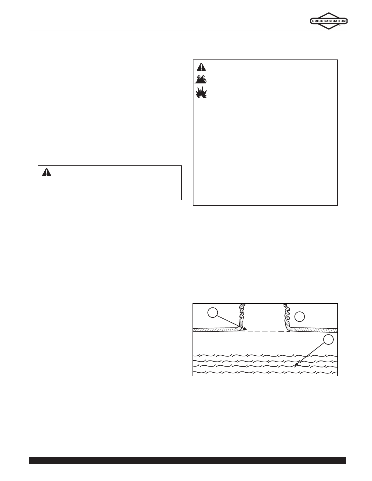
How to Add Fuel
1. Clean area around fuel cap. Remove cap.
2. Slowly add fuel and oil mixture (A, Figure 19) to the
fuel tank (B). Do not fill above the bottom of the fuel
tank neck (C).
3. Install fuel cap and let any spilled fuel evaporate
before starting engine.
Page 15

15
360
15
meters (
50
feet)
Figure 20
OPERATION
WARNING Objects thrown by the trimmer can
cause serious injury.
• Clear the area to be cut before each use. Remove
all objects such as broken glass, nails, wires, or
string, which could be thrown or become
entangled in the cutting attachment.
• Clear the area of children, bystanders, and pets.
• Keep all children, bystanders outside of a 50 ft (15
m) radius.
• Bystanders should be encouraged to wear eye
protection.
Inspect Working Area
Objects thrown by the trimmer can cause serious
injury. Before operating the trimmer, carefully inspect
the area and remove all objects that could be thrown
by, or entangled in, the cutting attachment, such as
rocks, broken glass, nails, wire, or other loose objects.
Keep all children and other bystanders at least 50 feet
(15 meters) away from where the trimmer is being
operated.
If anyone approaches while operating the trimmer,
release the throttle and stop the engine.
Inspect Cutting Attachments
Look for signs of damage to the cutting attachment.
Replace any cutting attachment and parts that are worn
out, bent, cracked, chipped, or damaged in any way.
If using the trimmer blade, be sure it is sharp. A dull
blade is more likely to snag and thrust.
Ensure the cutting attachment is installed correctly.
Ensure that the blade guard is securely installed and in
good condition.
Balancing the Trimmer on the Shoulder Harness
Hang the trimmer on the harness hook to check how it
balances.
Adjust the shoulder harness and the harness hanger on
the frame so that the handlebars in a comfortable operating position, and the trimmer hangs with its cutting
attachment a few inches above the ground (Figure 20).
Page 16

16
OPERATION
Starting the Engine
WARNING Gasoline and its vapors are
extremely flammable and explosive.
Fire or explosion can cause severe burns or
death.
When Starting Engine
• Ensure that spark plug, muffler, fuel cap and air
cleaner (if equipped) are in place and secured.
• Do not crank the engine with the spark plug
removed.
WARNING Running engine gives off carbon
monoxide, an odorless, colorless, poison gas.
Breathing carbon monoxide can cause headache, fatigue, dizziness, vomiting, confusion,
seizures, nausea, fainting or death.
• Operate equipment ONLY outdoors.
• Keep exhaust gas from entering a confined area
through windows, doors, ventilation intakes, or
other openings.
WARNING Exhaust heat/gases could ignite
combustibles or structures resulting in death,
serious injury or property damage. Contact
with the muffler area could cause burns resulting in serious injury.
• DO NOT touch hot parts.
• Allow equipment to cool before touching.
• Keep exhaust gas from entering a confined area
through windows, doors, ventilation intakes, or
other openings.
• Replacement parts must be the same and installed
in the same position as the original parts.
WARNING Rapid retraction of starter cord
(kickback) will pull hand and arm toward
engine faster than you can let go. Broken
bones, fractures, bruises, or sprains could
result.
• When starting engine, pull the starter cord slowly
until resistance is felt and then pull rapidly to avoid
kickback.
• Direct-coupled equipment components, such as
but not limited to blades, impellers, pulleys, and
sprockets, must be securely attached.
1. Place the machine on a hard, level surface.
2. Slide the stop/start switch (located on the hand grip)
to the Start position.
3. Place the choke lever in the closed (Up) position (A,
Figure 21).
NOTE: Do Not close the choke when starting a warm
engine.
4. Hold the machine firmly and pull the starter cord
slowly until resistance is felt. Then pull rapidly until
the engine starts.
5. After the engine has warmed up, move the choke
lever to the open (Down) position.
Stopping the Engine
1. Release throttle lever.
2. Set Stop Switch to the OFF position.
Figure 21
A
Page 17

17
Attachmen DO NOT TrimYou MAY Tri
Trimmer / Nylon
Head
• Grass
• Lawn Edges
• Borders
• Pasture
• Shrubs
• Trees
Brushcutter Blade
• Grass
• Pasture
• Ferns, Weeds,
Light Growth
• Lawn Edges
• Shrubs
• Trees
WARNING A worn, damaged, or cracked blade
can break, and pieces of the damaged blade can
become dangerous projectiles. A dull blade is more
likely to snag and thrust (kickback). Inspect the
blade regularly, and do not operate the trimmer with
a dull, damaged, or worn blade.
Figure 22
OPERATION
Trimmer Operation
Operating Position
Hold the trimmer firmly with both hands, with your
fingers and thumbs encircling the handles (Figure 22).
This will help keep the trimmer under control at all
times.
• Keep fi rm footing and balance.
• Do not overreach.
• Keep the cutting attachment below waist level.
• Keep all parts of your body away from the rotating
cutting attachment and hot surfaces.
Using a Nylon Trimmer-Line Head
Refer to the chart on this page for appropriate linecutting applications.
Line must be released with the trimmer-line head
spinning rapidly.
1. Hold the rotating cutting head horizontal to the
ground.
2. With the engine running at full speed, tap the
cutting-line head on hard, bare ground. Do not tap
the cutting-line head on pavement or concrete.
3. Each tap releases about two inches of line.
4. The blade on the deflector trims surplus line to correct
length. Avoid tapping the head more than once.
NOTE: Line feed will only operate if both lines still have
a minimum length of 1” (2.5 cm).
Using Brushcutter Blade
Refer to the chart on this page for appropriate blade
applications.
The blade supplied with the trimmer has a protective
cover surrounding the edge of the blade. For your
safety, and to protect the blade, the cover should be
installed whenever the trimmer is not in use or when
installing the blade.
Be sure to remove the blade cover before starting the
engine, or the blade cover may fly off at high speed.
Thrown Debris
The trimmer/brushcutter will throw debris in the direction of blade movement at the point of contact.
The cutting line head or blade rotate counterclockwise,
as viewed from the operator’s position.
• Tilting the cutting head to the right will throw debris
away from you.
• Tilting the cutting head to the left will throw debris
towards you.
• If the cutting head is held parallel to the ground,
debris will scatter in all directions, and there will be
greater friction which will wear out the cutting line or
blade sooner.
Page 18

18
Figure 23
OPERATION
Blade Thrust (Kickback)
WARNING Blade thrust (kickback) is the
sudden, forceful, and uncontrolled movement of a
blade-equipped trimmer that may occur if the blade
binds in the cut of if the blade strikes a solid object.
Blade thrust (kickback) throws the trimmer in the direction opposite blade rotation at the point of contact, and
the jolt received by the operator can result in further
loss of control (Figure 23).
• Replace or resharpen dull blades. Dull blades are more
likely to bind in the cut and cause blade thrust.
• Watch for hidden obstacles, such as rocks, stumps,
roots, etc., that could cause the blade to kickback if
struck. Blade thrust is more likely to occur in areas
where it is diffi cult to see what is being cut.
• Accelerate the engine to maximum speed before
starting the cut, and saw through with uniform pressure.
Trimming and Edging
• Use a nylon line for cutting against a hard surface.
• Work from an angle where debris that strikes the hard
surface will fl y away from you.
• Avoid contact with wires, wire fences, metal rods, etc.
Overlapping a wire will cause the nylon line to wrap
around the wire and break off.
Operating on Slopes
• Start on the low side of a slope, and work upward.
• Avoid steep slopes that would require holding the
cutting head above waist level.
• Avoid slippery slopes that might cause you to lose
your balance.
Page 19

19
MAINTENANCE
First 5 Hours
• Inspect equipment for damage
Every 8 Hours or Daily
• Clean debris from cutting head and engine
• Clean and inspect air filter*
Every 50 Hours or Annually *
•
Inspect cutting head assembly for damage or missing parts
• Replace engine air filter*
• Replace spark plug
•
Inspect muffler and spark arrester for debris and damage
• Clean cooling system*
•
Clean and inspect brushcutter blade or trimmer line
* Service more often under dirty or dusty conditions
To help you properly care for your trimmer, the following pages include a maintenance schedule, routine
inspection procedures, and simple maintenance procedures using basic hand tools.
Other service tasks that are more difficult or that
require special tools are best handled by your authorized service technician.
WARNING Improperly maintaining the trimmer,
or failure to correct a problem before operation, can
cause a malfunction in which you can be seriously
hurt or killed. Always follow the inspection and maintenance recommendations and schedules in this
manual.
WARNING Failure to properly follow
maintenance instructions and precautions can
cause you to be seriously hurt or killed and will void
the warranty. Always follow the procedures and
precautions in the manual.
WARNING
Unintentional sparking can result in fire or
electric shock.
Unintentional start-up can result in entangle-
ment, traumatic amputation, or laceration.
Fire hazard.
Before performing adjustments or repairs:
• Disconnect the spark plug wire and keep it away
from the spark plug.
• Use only correct tools.
• Replacement parts must be the same and installed
in the same position as the original parts.
• STOP engine.
• Avoid serious burns. Allow all parts to cool before
working on machine.
Maintenance Schedule
Follow the hourly or calendar intervals, whichever
occurs first. More frequent service is required when
operating in adverse conditions noted below.
Page 20

20
WARNING Gasoline and its vapors are
extremely flammable and explosive.
Fire or explosion can cause severe burns or
death.
• Never start or run the engine with the air
cleaner assembly or the air filter removed.
Figure 25
Figure 24
B
0.7 mm
MAINTENANCE
Spark Plug Maintenance
Changing the spark plug will help the engine to start
easier and run better.
1. Clean area around spark plug.
2. Remove and inspect spark plug (A, Figure 24).
3. Check the gap with wire feeler gauge (B) and reset
to recommended gap if necessary (see Specifications).
4. Replace spark plug if electrodes are pitted or burned,
or the porcelain is cracked.
5. Install spark plug and tighten to 180 lb. in. (20 Nm).
Air Filter Maintenance
NOTICE: Do not use pressurized air or solvents to clean
the filter. Pressurized air can damage the filter and
solvents will dissolve the filter.
1. Remove air cleaner cover (A, Figure 25) and the filter
element (B).
2. Wash foam element in liquid detergent and water to
remove dirt.
3. Wrap foam element in a clean cloth and squeeze dry.
4. Saturate foam element with clean engine oil. Squeeze
to remove excess oil.
5. Reassemble air cleaner.
NOTICE: Make sure the air filter element and cover are
fitted correctly. Warranty coverage will be void if engine
is damaged due to incorrect installation of filter.
A
A
B
Page 21

21
MAINTENANCE
Spark Plug Maintenance
Inspect Trimmer Line Head
Ensure the nylon line is only sticking out of the metal
grommets on the side of the cutting head. If the line
has come off the spool, proceed to Installing Trimmer
Line in the Assembly Section to replace the trimmer
line.
Examine the entire head area, including the debris
shield, and clear or clean it free from dirt, debris, loose
string, wire, or any other foreign material.
Inspect Brushcutter Blade
WARNING A worn, damaged, or cracked
blade can break, and pieces of the damaged blade
can become dangerous projectiles. A dull blade is
more likely to snag and thrust (kickback). Inspect the
blade regularly, and do not operate the trimmer with
a dull, damaged, or worn blade.
Before each use, check the blade for wear and damage,
and check the tightness of the securing nut. Examine the
entire head area, including the debris shield, and clear or
clean it free from dirt, debris, loose string, wire, or any
other foreign material.
Any blade that is worn out, bent, cracked, chipped, or
damaged in any other way, must be replaced.
Page 22

22
Protect Fuel System
Fuel can become stale when stored over 30 days. Stale
fuel causes acid and gum deposits to form in the fuel
system or on essential carburetor parts. To keep fuel
fresh, use a quality fuel stabilizer.
There is no need to drain gasoline from the engine if a
fuel stabilizer is added according to instructions. Run the
engine for 2 minutes to circulate the stabilizer throughout
the fuel system. The engine and fuel can then be stored
up to 3 months.
If gasoline in the engine has not been treated with a fuel
stabilizer , it must be drained into an approved container.
The use of a fuel stabilizer in the storage container is
recommended to maintain freshness.
Clean the Unit
Wipe clean the handle, cutter head, guard, and engine
parts with a damp cloth. To avoid fuel contamination or
equipment damage, Do Not apply water or other liquids
directly to the unit.
Storage Safety
Allow the engine to cool before storage. Store the equipment in a clean, dry environment to avoid excessive
dust, dirt, or moisture. Secure the unit to prevent tipping
or falling during storage.
Store the fuel container out of the reach of children in a
well-ventilated, unoccupied building.
Do not store equipment or fuel container inside where
fumes may reach an open flame, spark, or pilot light
such as in a water heater, furnace, clothes dryer , or other
gas appliance.
STORAGE
WARNING Gasoline and its vapors are
extremely fl ammable and explosive.
Fire or explosion can cause severe burns or
death.
When Storing Fuel or Equipment with Fuel in Tank
•
Store away from furnaces, stoves, water heaters
or other appliances that have pilot lights or other
ignition sources because they can ignite fuel
vapors.
Page 23

23
REMEDY
LOOK FORPROBLEM
Engine will not start
Electrode is wet or foule Clean or replace the spark plug
Cracked insulator Replace spark plug
STOP SWITCH in OFF position
Turn switch to ON position
Incorrect spark plug gap Adjust gap to value listed in Specifications
Engine flooded Crank engine with choke open to clear excess fuel
Use of incorrect or stale fuel Drain and replace with correct fuel/oil mixture
No fuel in tank Refuel
Insufficient Power
Clogged air filter Clean air filter
Machine is overworked Operate properly - do not overload
Debris build-up on cutting head
Remove debris from cutting head
Engine overheating Remove debris from engine
Use of incorrect or stale fuel Drain and replace with correct fuel/oil mixture
Engine Stops during
Operation
Switch is bumped Place switch in ON position
Fuel tank empty Refuel
Engine is Difficult to
Stop
Stop wire disconnected from
switch
Attach stop wire to switch
Unit Main Body
Loose cutting head Tighten cutting head securely
Broken clutch spring, bent
main shaft
See authorized dealer
Worn shaft bearings See authorized dealer
Loose gearhead See authorized dealer
Blade bent or damaged Replace blade
TROUBLESHOOTING
Page 24

24
NOTES
Page 25

25
BRIGGS & STRATTON POWER PRODUCTS GROUP, L.L.C. OWNER WARRANTY POLICY
LIMITED WARRANTY
ABOUT YOUR WARRANTY
WARRANTY PERIOD
CONSUMER USE - 180 DAYS
COMMERCIAL USE - 90 DAYS
WARRANTY
Briggs & Stratton Power Products Group, LLC will repair or replace, free of charge, any part (s) of the equipment that is defective in material or workmanship or both. This warranty is effective for the time periods and
subject to the conditions stated below. For warranty service, find the nearest Authorized Service Dealer using
our dealer locator at www.BriggsandStratton.com or www.Murray.com.
There is no other express warranty. Implied warranties, including those of merchantability and fitness for a
particular purpose, are limited to one year from purchase or to the extent permitted by law. Liability for incidental
or consequential damages are excluded to the extent exclusion is permitted by law.
Some states or countries do not allow limitations on how long an implied warranty lasts, and some states or
countries do not allow the exclusion or limitation of incidental or consequential damages, so the above limitation
and exclusion may not apply to you. This warranty gives you specific legal rights and you may also have other
rights which vary from state to state or country to country.
The warranty period begins on the date of purchase by the first retail consumer or commercial end user, and continues for the period of time stated above. “Consumer use” means personal residential household use by a retail
consumer. “Commercial use” means all other uses, including use for commercial, income producing or rental
purposes. Once equipment has experienced commercial use, it shall thereafter be considered as commercial use
for purposes of this warranty.
NO WARRANTY REGISTRATION IS NECESSARY TO OBTAIN WARRANTY ON BRIGGS & STRATTON PRODUCTS. SAVE YOUR PROOF OF PURCHASE RECEIPT. IF YOU DO NOT PROVIDE PROOF OF THE INITIAL
PURCHASE DATE AT THE TIME WARRANTY SERVICE IS REQUESTED, THE MANUFACTURING DATE OF
THE PRODUCT WILL BE USED TO DETERMINE THE WARRANTY PERIOD.
Most warranty repairs are handled routinely, but sometimes requests for warranty service may not be appropriate.
This warranty only covers defects in materials or workmanship. It does not cover damage caused by improper use
or abuse, improper maintenance or repair, normal wear and tear, or stale or unapproved fuel.
Improper Use and Abuse - The proper, intended use of this product is described in the Operator’s Manual. Using
the product in a way not described in the Operator’s Manual or using the product after it has been damaged will void
your warranty. Warranty is not allowed if the serial number on the product has been removed or the product has
been altered or modified in any way, or if the product has evidence of abuse such as impact damage, or
water/chemical corrosion damage.
Improper Maintenance or Repair - This product must be maintained according to the procedures and schedules
provided in the Operator’s Manual, and serviced or repaired using genuine Briggs & Stratton parts. Damage caused
by lack of maintenance or use of non-original parts is not covered by warranty.
Normal Wear - Like all mechanical devices, your unit is subject to wear even when properly maintained. This
warranty does not cover repairs when normal use has exhausted the life of a part or the equipment. Maintenance
and wear items such as filters, belts, cutting blades, and brake pads (engine brake pads are covered) are not
covered by warranty due to wear characteristics alone, unless the cause is due to defects in material or workmanship.
Stale Fuel - In order to function correctly, this product requires fresh fuel that conforms to the criteria specified in
the Operator’s Manual. Damage caused by stale fuel (carburetor leaks, clogged fuel tubes, sticking valves, etc) is
not covered by warranty.
Page 26

26
Model # 866032 (BP33-W)
Engine Displacement (cc)
Width of Cut (nylon)
Diameter of Nylon String
Width of Cut (blade)
Fuel Tank Capacity
Weight
paG gulP krapS
euqroT gulP krapS
32.6
30 cm
2.4 mm
41 cm
0.9 L
9.6 kg
).ni 30.0 - 20.0( mm 67.0 - 15.0
).ni .bl 081( mN 02
42.7
30 cm
2.4 mm
41 cm
0.9 L
10 kg
).ni
30.0 - 20.0( mm 67.0 - 15.0
).ni .bl 081( mN 02
Model # 866033 (BP43-W)
Engine Displacement (cc)
Width of Cut (nylon)
Diameter of Nylon String
Width of Cut (blade)
Fuel Tank Capacity
Weight
paG gulP krapS
euqroT gulP krapS
SPECIFICATIONS
Page 27

27
 Loading...