

Briggs & Stratton 950 Series Advance Product Service Information
Not for Reproduction
ADVANCE PRODUCT SERVICE INFORMATION
APSI NO: 101
DATE: AUGUST 2014
SUBJECT: 950 SERIES™ UTILITY ENGINE
MODELS: 130G00 OHV HORIZONTAL SHAFT
This APSI provides basic servicing information in advance of the repair manual under development. Systems
testing, troubleshooting, and component removal and installation procedures are common with most other
single-cylinder horizontal-shaft OHV engines. See the Illustrated Parts List for service part numbers. The
specifications, part numbers, and procedures provided here are preliminary and subject to change.
B
A
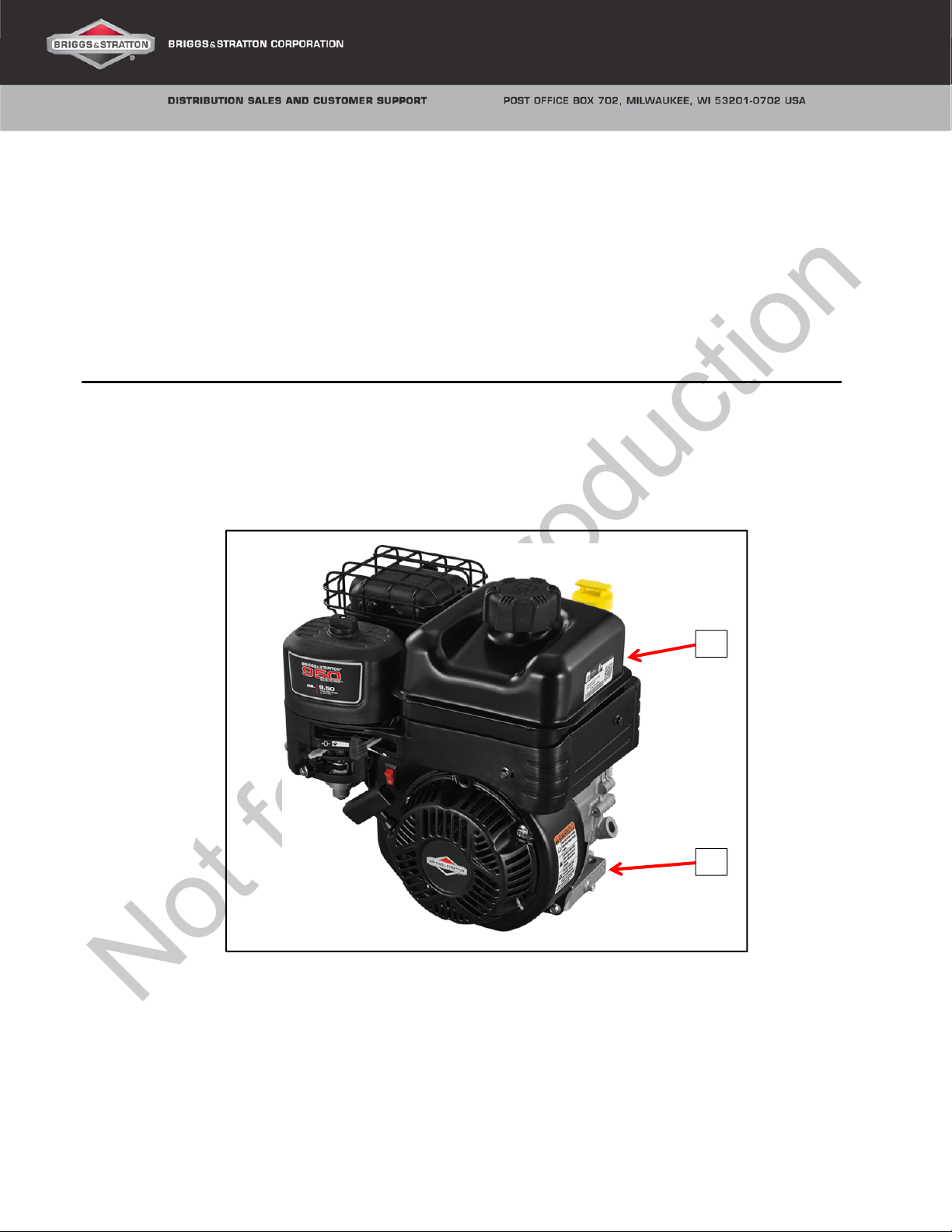
MODEL IDENTIFICATION LOCATION
The Model-Type-Trim and Code numbers (A) are printed or etched into the edge of the cylinder base below
the fuel tank. The bar code serial number label (B) is attached to the side of the fuel tank.
Copyright © Briggs & Stratton Corporation Page 1 of 13
All language translations of this document are
derived from the original English source file.
Not for Reproduction
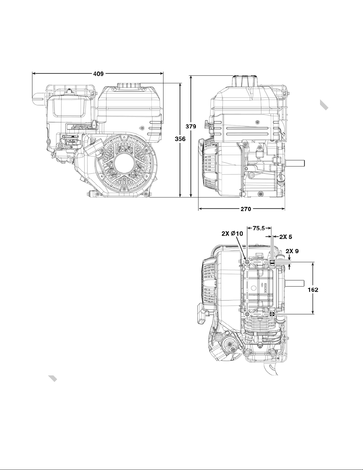
OVERALL ENGINE DIMENSIONS (Millimeters)
Page 2 of 13
Not for Reproduction
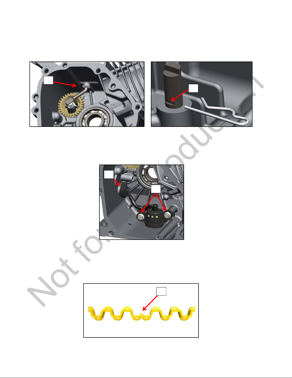
GOVERNOR SHAFT INSTALLATION
There is a washer (A) that must be fitted to the governor shaft before installation into the cylinder. Secure the
governor shaft from the outside with the retaining clip. The straight leg of the clip fits into the groove (B) of
the governor shaft.
A
B
OPTIONAL LOW-OIL SENSOR INSTALLATION
The low-oil sensor installs inside the cylinder with two screws (C). Tighten the screws to 60 lb-in (6.8 Nm).
Next, route the sensor harness (D) through the opening in the cylinder. Secure the harness from the outside
with the hex nut and tighten to 40 lb-in (4.5 Nm). Also see Low-Oil Module Installation.
D
PISTON ASSEMBLY
When installing the oil ring expander, ensure that the ends at the expander gap (E) point up toward the piston
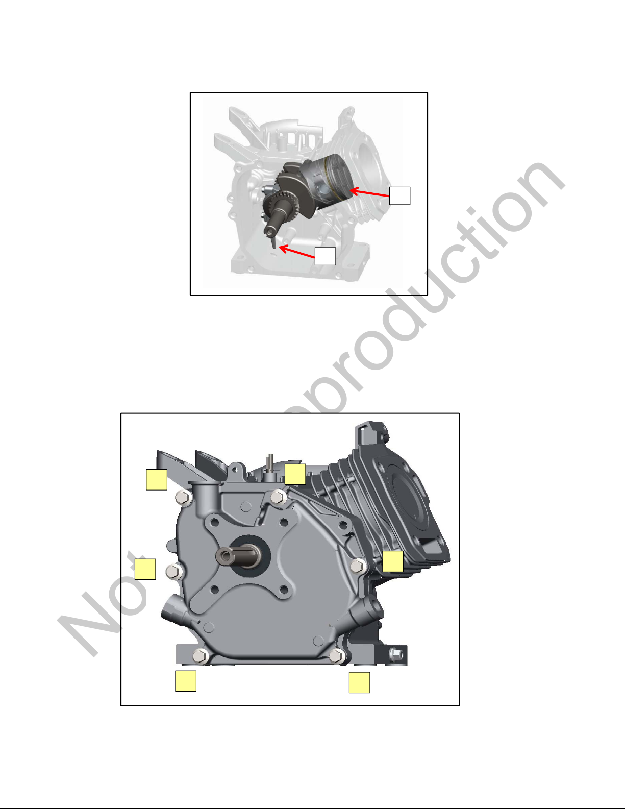
crown. The lettering on the center and top piston rings must also face up toward the crown. When installi ng
the piston assembly into the bore, the notch in the piston (F) and the oil dipper on the connecting rod (G) will
face down toward the push rods.
C
E
Page 3 of 13
Not for Reproduction
F
G
CRANKCASE COVER INSTALLATION
1) Make sure the mating surfaces on the cover and the cylinder are clean and dry.
2) Install the new gasket over the dowel pins, then carefully install the cover over the crankshaft and
press into place.
3) Start the cover screws by hand and then step-torque in the sequence shown below to 220 lb-in (24.9
Nm).
4
2
6
1
5
3
Page 4 of 13
 Loading...