

Briggs & Stratton 86262GS Familiarization & Troubleshooting Manual
Familiarization & Troubleshooting Guide
GENERATOR
For Briggs & Stratton Discount Parts Call 606-678-9623 or 606-561-4983
www.mymowerparts.com

FFOORRWWAARRDD
This guide has been written and published by Briggs & Stratton Corporation to aid our
dealers’ mechanics and company service personnel when servicing the products described
herein.
It is assumed that these personnel are familiar with the servicing procedures for these
products, or like or similar products, manufactured by Briggs & Stratton Power Products. It is
also assumed that they have been trained in the recommended servicing procedures for these
products, which includes the use of mechanics hand tools and any special tools that might be
required.
Proper service and repair is important to the safe, economical and reliable operation of all
engine driven systems. The troubleshooting, testing, service and repair procedures described
in this guide are effective methods of performing such operations.
We could not possibly know of and advise the service trade of all conceivable procedures or
methods by which a service might be performed, nor of any possible hazards and/or results
of each procedure or method. We have not undertaken any such wide evaluation. Therefore,
anyone who uses a procedure or method not described by the manufacturer must first satisfy
himself that neither his safety, nor the safety of the product, will be endangered by the
service or operating procedure selected.
All information, illustrations, and specifications contained in this guide are based on the latest
production information available at the time of publication. However, Briggs & Stratton
Corporation reserves the right to change, alter, or otherwise improve the product at any time
without prior notice.
Some components or assemblies of the product described in this guide may not be considered
repairable. Disassembly, repair and reassembly of such components may not be included in
this guide.
Service and repair instructions for the engines used to power these products are not covered
in this guide. Engine service and repair instructions are furnished by the engine manufacturer.
CCooppyyrriigghhtt ©© 22000066 BBrriiggggss && SSttrraattttoonn CCoorrppoorraattiioonn
All rights reserved.
No part of this material may be reproduced or transmitted, in any form or by any means,
electronic or mechanical, including photocopying, recording or by any information storage
and retrieval system, without prior permission in writing from Briggs & Stratton Corporation.
Generator
Fundamentals
Basic Electricity 3
Magnetism and Electricity 3
Electro-Motive Force 4
Electromagnetism 7
Direct Current (DC) 8
Alternating Current (AC) 8
Volt 10
Ampere 10
Ohm 10
Ohm’s Law 11
The Watt 11
Electrical Formulas 12
The Series Circuit 13
The Parallel Circuit 13
The Series-Parallel Circuit 14
Simple Alternator 17
Simple Alternator Operation 17
Generator Components
And Systems
Generator Components 19
Rotor Assembly 20
Stator Assembly 21
Switches 23
Fuses 26
Circuit Breakers 26
Solenoids 27
Relays 28
Resistors 29
Transformers 31
Condensers 32
Rectifiers 33
Transistors 34
Brushes and Brush Holders 35
Voltage Regulator 37
Generator Systems 41
Revolving Field Excitation Methods 42
Direct Excitation 42
The Brushless Excitation Method 44
Field Boost Assembly 45
Power Factor 46
Oil Pressure Switch On “GN” Engines 49
Typical Automatic Idle Control System 50
Early V-Twin Engine Idle Control 51
Idle Control on “GN”
190, 220, 320, 360, & 410 ENGINES 51
“XL” And “MC” Idle Control On
480 & 570 V-Twin Engines 53
1
GENERAC®PORTABLE PRODUCTS
Table of Contents
Portable Generator Familiarization & Troubleshooting Guide
Generator Diagnostics And
Adjustments
Troubleshooting Idle Controls 56
Troubleshooting Flowchart For
“Direct Excited” (Brush Type)
Generators 68
Troubleshooting Flowchart For
(Brush Type) Generators With
“Two Board” Regulation 76
Troubleshooting Flowchart For
“Sincro® Wound” (Brushless Type)
Generators 84
Voltage Regulator Adjustments 90
Generator Assemblies
Generac® Wound Generators 94
Disassembly 94
Assembly 101
Sincro® Wound Generators 109
Disassembly 109
Assembly 112
Appendix A
Generac® Torque Table 117
Generac® Receptacles And Plugs 118
Glossary 120
2
GENERAC®PORTABLE PRODUCTS
Table of Contents
Portable Generator Familiarization & Troubleshooting Guide
BASIC ELECTRICITY
Section 1 • Generator Fundamentals
Portable Generator Familiarization & Troubleshooting Guide
3
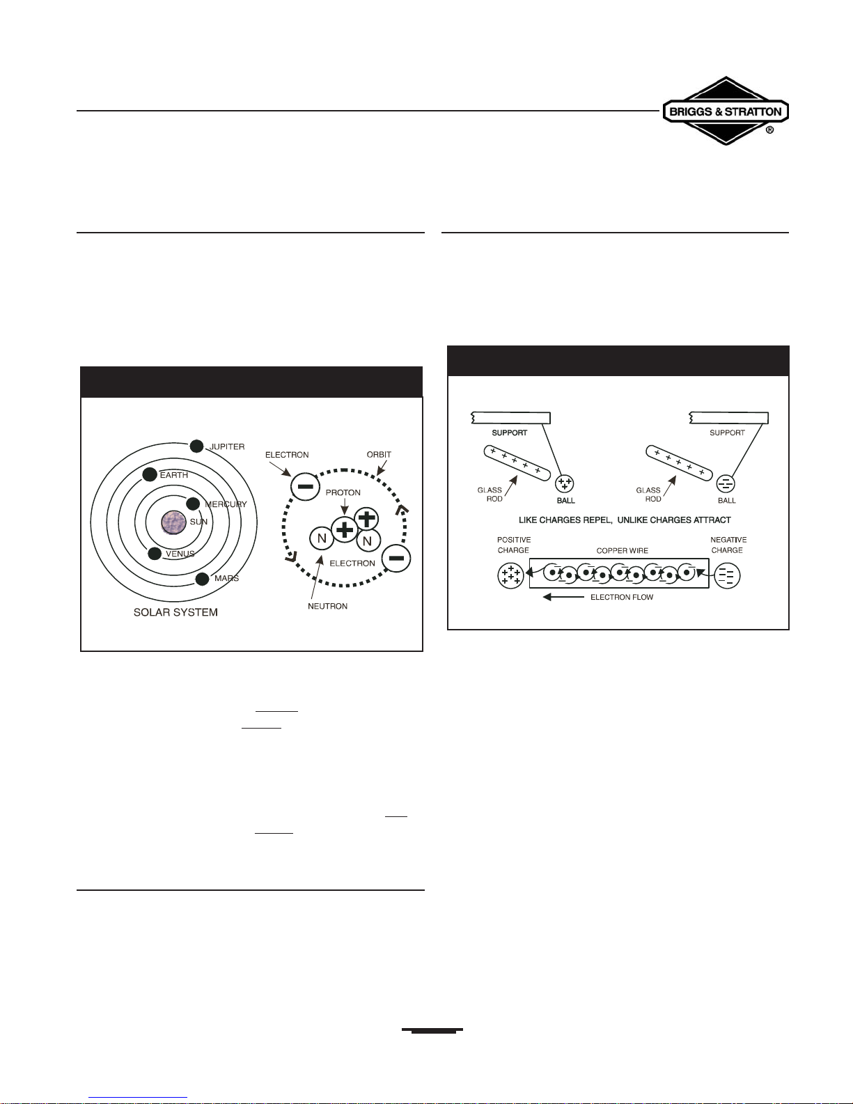
The Atom
All matter is made up of atoms.An atom may be compared
to a solar system that has several planets revolving around
the sun.There are more than 100 different kinds of atoms.
The various atoms combined together form all known
substances.
The structure of the helium atom is shown in
Figure 1.1.
Negatively (-) charged particles called electrons revolve
around a positively charged nucleus.The nucleus is made up
of both protons, which have a positiv
e (+) electrical charge,
and neutrons, which have a neutral (N) electrical charge.
The negative and positive particles that make up an atom act
much like the north and south poles of a magnet, in which
the north pole is positive (+) and the south pole is
negative (-).
Every child who has played with a magnet knows that lik
e
poles repel each other and unlike poles attract each
other.
Magnetism and Electricity
Like the poles of a magnet, atomic particles with the same
charges repel each other and the particles with different
charges attract each other. In a normal atom, the positive
charge of the nucleus exactly balances the negative charge of
the electrons that rotate around it.
Borrowing Of Electrons
If an atom loses electrons, the positive (+) charge of the
nucleus and the negative (-) charge of the electrons
revolving around it is no longer balanced. The atom then
becomes positively charged.The natural tendency of the
positively charged atom is to attract any other negative
charges, such as an electron from another atom (Figure 1.2).
The positively charged atom attempts to return to a
balanced (or neutral) state and will “borrow” an electron
from a neighboring atom.When an atom borrows an
electron from its neighbor, the neighbor then becomes
positively charged.This starts a “chain reaction” in which
each atom in turn borrows an electron from its neighboring
atom.
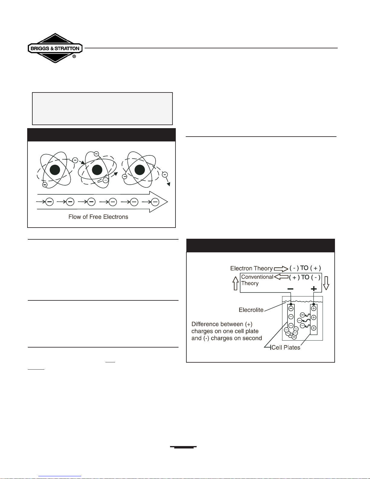
This borrowing of electrons creates a flow of current
that continues until all the atoms have achieved a
state of balance.
Figure 1.3 illustrates the transfer of electrons from one atom
to the next and the resulting flow of free electrons that
occurs.This may be difficult to visualize, unless you
remember that an electron is so small that it finds great
empty spaces for free travel, even in a solid substance.
Figure 1.1 — The Helium Atom
Figure 1.2 — Magnetism and Electricity
Section 1 • Generator Fundamentals
Portable Generator Familiarization & Troubleshooting Guide
Conductors and Non-Conductors
Some materials (such as copper or silver) will readily
transfer electrons from atom to atom.These materials are
called conductors. Other materials hold their electrons
very tightly and are said to have “bound” electrons.These
non-conductors, materials such as wood, glass or rubber,
are often used as insulators.
Current Flow Versus Electricity
Electricity is created by the action of electrons in motion.
Current flow is the flow of free electrons through a
conductive path (circuit).Thus, electricity is a form of energy
while current flow is the harnessing of that energy.
Two Theories of Current Flow
The Electron Theory: As previously discussed, current
flow is based on the fact that: “like charges repel and
unlike charges attract.” An electron, a negatively (-)
charged particle, is attracted to a proton, a positively(+)
charged particle. The Electron Theory of Electricity states
that electron or current flow in a circuit goes from the
negative side of that circuit to the positive side.
The Conventional Theory: This theory states that
current or electron flow in a circuit goes from the positive
side of that circuit to its negative side.
The difference between conventional and electron theories
is mentioned because the conventional theory is more
commonly used in everyday applications. For this guide,
however, we will use the Electron Theory.
Electro-Motive Force
Current flow occurs in a conductor only when there is a
difference in electrical “potential” and when there is a
complete path or circuit for electron flow.The force that
causes the electrons to flow is called:
“Electro-Motive Force” or ”EMF.” This force is equal
to the difference in electrical potential across the circuit.
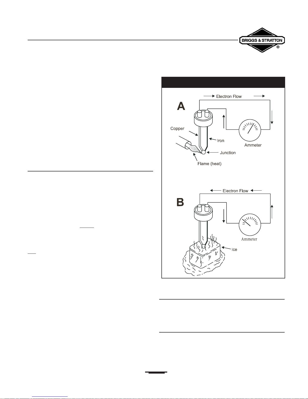
To illustrate the difference in potential, consider a storage
battery as a model.This type of battery consists of two
metal plates of different elements immersed in a fluid.A
chemical reaction causes an electrical charge to be created
on each of the metal plates.The fluid (called “electrolyte”)
carries electrons away from one plate and deposits them on
the other plate (Figure 1.4).
The plate that has gained electrons has become negatively
charged.This creates a difference in electrical potential
between the two metal plates. If a conductor is now
connected across the two metal plates, a circuit is completed
and the result is a flow of electrons to the positively charged
plate.
As long as there is a difference in electrical potential
between the two plates (positive versus negative
charge), current continues to flow.
4
Electrical current flow is based on the
principle:
That atoms have the ability to readily
transfer and borrow electrons
Figure 1.3 — Transfer of Electrons
Figure 1.4 — Electron Flow
Several basic methods may be used to create an electrical
current flow. Four methods will be discussed here.All of
these methods are based on a fundamental law that energy
can never be created or destroyed but can be changed into
other forms of energy.Thus, chemical, heat, light and
magnetic energy can be changed into electrical energy.
The four basic methods of creating electrical current flow
are:
• Chemical energy (e.g., storage battery)
• Heat energy (e.g., thermocouple)
• Light energy (e.g., photo-electric)
• Magnetic energy (e.g., alternator or generator)
The Thermocouple
When two dissimilar metals are welded together and the
welded junction is heated or cooled, an electro-motive force
(EMF) is produced.The joining process appears to disturb
the atomic orbits at the junction, so that the outer electrons
in both metals are loosely held.Any small addition or
subtraction of heat energy will set these electrons free.
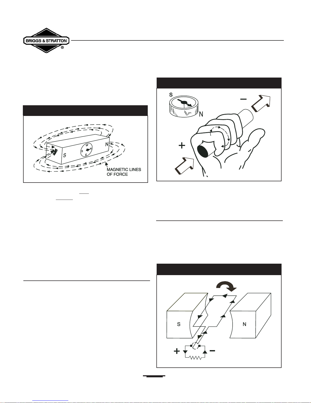
Figure 1.5 shows a union between iron and copper wires,
this union forms a thermocouple. In Figure 1.5A, the heat of
the flame has caused the copper
atoms to lose electrons.
The copper draws electrons from the iron and a current
flow in one direction is produced.
In Figure 1.5B, the wire junction has been cooled, causing the
ir
on atoms to lose electrons and attract electrons from the
copper. The resulting current flow is then reversed from that
of Figure 1.5A.
Photoelectric Cell
Copper oxide and selenium oxide are sensitive to rays of
light. Materials that create a current flow when exposed to
light are said to be “photo-voltaic.”
Magnetic Energy
Magnetism is closely related to electricity. It can be used to
produce electricity and electricity can be used to produce
magnetism.A study of one must, therefore, include a study of
the other.
5
CREATING CURRENT FLOW
Section 1 • Generator Fundamentals
Portable Generator Familiarization & Troubleshooting Guide
Figure 1.5 — The Thermocouple
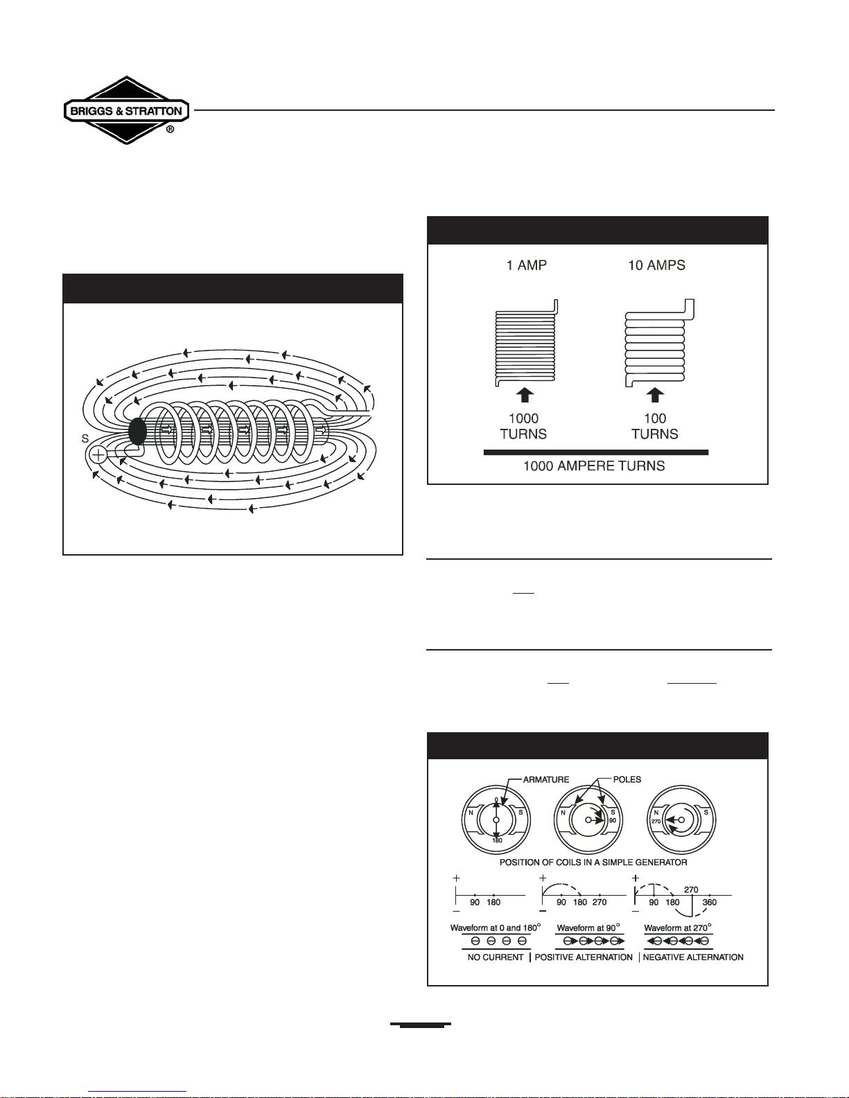
Magnetic “lines of force” surround a magnet.These lines of
force are concentrated at the magnet’s NORTH and SOUTH
poles and are often called “lines of flux”
(Figure 1.6).
The flux lines are directed a
way from the magnet at its
north pole and re-enter the magnet at its south pole. Like
the positive (+) and negative (-) electrical charges previously
discussed, the same magnetic poles repel each other and
unlike poles attract each other.
When discussing magnetism, two terms should be defined:
• Permeability: The ease with which any given
substance can be magnetized.
• Retentivity: The ability of a substance to retain its
magnetism when an external magnetic
field is removed (also known as “Residual
Magnetism”).
Current Flow and Magnetism
All conductors through which an electrical current is flowing
have a magnetic field surrounding them. The greater the
current (electron) flow, the stronger or more concentrated
the magnetic field.To determine the direction of magnetic
lines of force around a wire, you can use a simple rule called
the “Right Hand Rule.” Simply place your right hand
around the wire with your thumb pointing in the direction
of the current flow (positive to negative). The fingers then
point in the direction of the magnetic lines of force
(Figure 1.7).
When conductor wires are formed into a coil, a north
magnetic pole is created in half of the coil and a south
magnetic pole is created in the other half.
Determine polarity (direction of the lines of force) in the
coil by grasping it in the right hand with the fingers pointing
in the direction of current flow.The thumb then points to
the coil’s north pole.
Simple Permanent Magnet Generator
When a wire is moved so that it intersects (cuts across) a
magnetic field, an electro-motive force (EMF) is induced in
that wire (Figure 1.8).This is the principle upon which a
rotating armature generator is based.
6
Section 1 • Generator Fundamentals
Portable Generator Familiarization & Troubleshooting Guide
Figure 1.6 — Lines of Flux Around A Magnet
Figure 1.7 — The Right Hand Rule
Figure 1.8 — Simple Revolving Armature Generator

Section 1 • Generator Fundamentals
Portable Generator Familiarization & Troubleshooting Guide
Electromagnetic Induction
In 1831, scientists observed that a conductor moving
through a magnetic field would have a voltage or electromotive force (EMF) induced into itself. Electromagnetic
induction may be defined as the action of inducing of a
voltage into a conductor by moving it through a magnetic
field.This principle is illustrated in Figure 1.9.
A straight wire conductor is moving through the magnetic
field of a horseshoe magnet. If a sensitive voltmeter were
attached to the ends of the wire conductor, a small voltage
would be indicated as the wire moved through the magnetic
field. However, if the wire conductor were moved parallel to
the lines of magnetic force, no voltage would be indicated.
The greater the strength of the magnetic field through which
the wire conductor is moved, the greater the induced
voltage in the conductor.
Another familiar form of electromagnetic induction is the
automotive engine ignition coil. Current flow through a
primary coil of wires creates a magnetic field around that
coil, which then cuts through a secondary coil of wires.
When the current flow through the primary wire coil is
interrupted, by opening a set of breaker points, the collapse
of the magnetic field induces an electro-motive force (EMF)
in the secondary coil (Figure 1.10)
Electromagnetism
The previous paragraph explained that magnetic lines of
force, cutting through the stationary windings of the stator
assembly, would induce an EMF into those windings.
Conversely, when a current flows through a wire conductor,
a magnetic field is created around that wire.The number of
lines of magnetic force, or strength of the magnetic field,
increases as the current is increased through the conductor.
When a current-carrying wire is wound into a number of
loops, to form a coil, the magnetic field created is the sum of
all single-loop magnetic fields added together.With lines of
magnetic force entering the coil at one end and leaving at
the other end, a north and south pole are formed at the coil
ends, as in a bar magnet (Figure 1.11).
7
Figure 1.9 — Electromagnetic Induction
Figure 1.10 — Typical Automotive Ignition System
Figure 1.11 — Magnetic Field Around A Coil Of Wire
If the coil is wound around a core of magnetic material, such
as iron, the strength of the magnetic field at the north and
south poles is greatly increased (Figure 1.12).
This happens because air is a poor conductor of magnetic
lines and iron is a very good conductor. Using iron in a
magnetic path may increase the magnetic strength of a coil
by 2500 times over that of air.
The strength of the magnetic poles in a coil of wire is
directly proportional to:
The number of turns of wire.
The current (in amperes) flowing through the wire.
A coil carring a current of one ampere through 1000 turns
of wire and another coil carring 10 amperes through 100
coils of wire will each create a magnetic field strength 1000
ampere-turns (Figure 1.13).
The term “ampere-turns” is the measure of the strength
of a magnetic field.
Direct Current (DC)
The current flow created by a storage battery flows through
a conductor in one
direction only.This type of current flow
is called direct current or (DC).
Alternating Current (AC)
Alternating current or (AC) is the flow of electrons
through a conductor first in one direction and then in the
other. This can be explained by showing the operation of a
simple alternating current (AC) generator (Figure 1.14).
8
Section 1 • Generator Fundamentals
Portable Generator Familiarization & Troubleshooting Guide
Figure 1.12 — Iron Core Increases Strength of Field
Figure 1.13 — Example of “Ampere-Turns”
Figure 1.14 — An Aternating Current Generator
Section 1 • Generator Fundamentals
Portable Generator Familiarization & Troubleshooting Guide
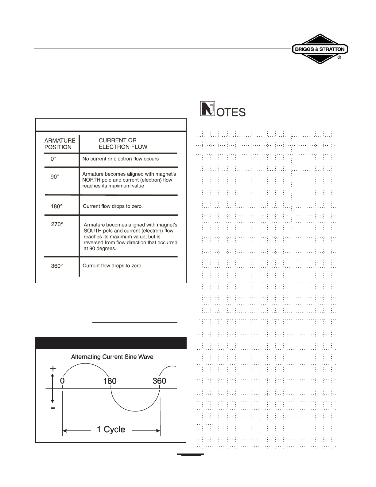
The flow of electrons changes direction according to the
rotating armature's position in relation to the poles of a
magnetic field (See the Table 1.1).
A wave diagram (sine wave) of alternating current shows
that current goes from a zero value to maximum positive
value (0°- 90° degrees), and then returns to zero (Figure
1.15).Two such current reversals (1 positive and 1 negative)
are called “one cycle.” The n
umber of cycles_per second,is
called frequency and is often stated as 'Hertz or “CPS.”
9
Table 1.1 — Current Flow Pattern
Figure 1.15 — An Alternating Current Sine Wave
UNITS OF ELECTRICAL MEASUREMENT
Section 1 • Generator Fundamentals
Portable Generator Familiarization & Troubleshooting Guide
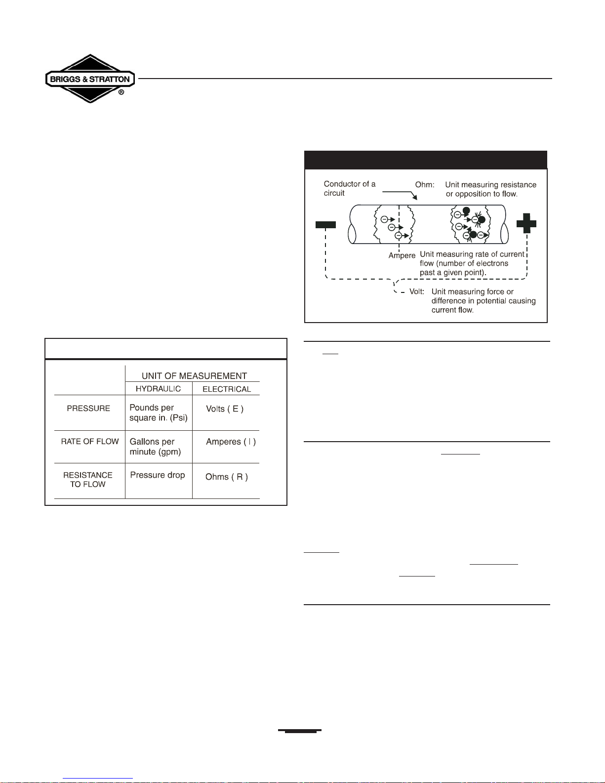
Just as a hydraulic system must have specific values:
• Rate of flow.
• Pressure.
• Resistance to flow.
Relavent established values can also be expressed for an
electrical circuit. Fluid flow values in a hydraulic system are
generally expressed as:
• Gallons per minute.
• Pounds per square inch.
• Pressure drop or pressure differential.
Electron flow (current) through a conductor can be
compared to the flow of hydraulic fluid through a hose
(Table 1.2).
The units of measure for an electrical circuit are:
• Volts - Pressure.
• Amperes - Rate of Flow.
• Ohms - Resistance to Flow. (Figure 1.16)
Ampere - Unit of Current Flow
The rate of electron flow through a conductor is measured
in amperes, which is a measurement of electrons flowing
past a given point in a given time. One ampere is equal to a
little over six thousand million billion electrons per second!
Written numerically, the figure looks like this:
6,000,000,000,000,000,000.
Volt - Unit of Pressure
The volt is a measurement of the diff
erence in electrical
potential (EMF) that causes electrons to flow in a circuit.This
difference in electrical potential (or electro-motive force)
may be described as the difference between the number of
positive charges and the number of negative charges.Thus,
voltage may be described as the potential of electrical
unbalance and current flow is the attempt to regain that
balance.
One v
olt is the amount of electro-motive force (EMF) that
will result in a current (electron) flow of one ampere
through a resistance of one ohm.
Ohm - Unit of Resistance
The electron may be compared to an individual trying to
make his way through a crowd of people, meeting the
resistance of human bodies every step of the way. In any
conductor or circuit, there is a resistance to electron flow.
10
Table 1.2 — Hydraulic Flow Versus Current Flow
Figure 1.16 — Electrical Measurement Units
A conductor’s resistance depends on:
• Its construction.
• It’s cross-sectional area.
• It’s length.
• It’s temperature.
One ohm is the amount of resistance that will permit one
ampere of current to flow in a conductor when one volt of
electro-motive force is applied.
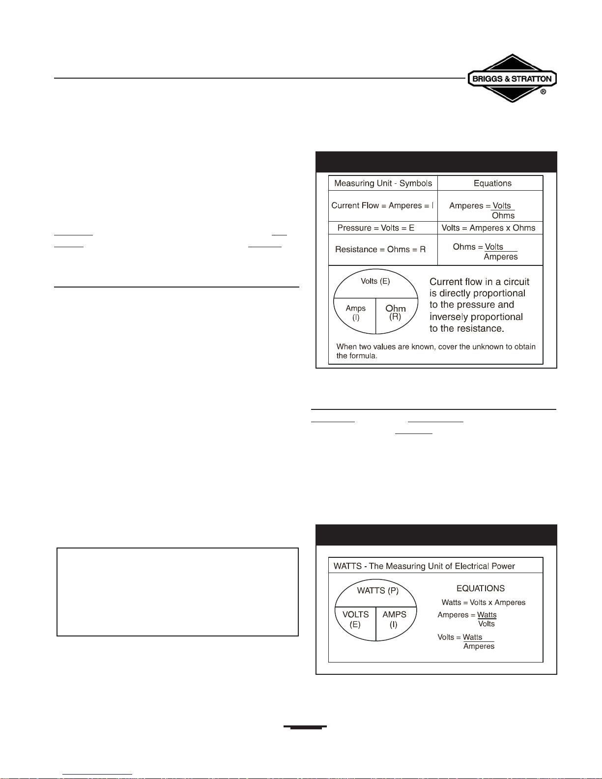
Ohm’s Law
In any circuit through which electrical current is flowing,
consider these three factors:
• Pressure (EMF) (in volts) is the potential that causes
current to flow.
• Resistance (in ohms) is the opposition that must be
overcome before current can flow.
• Flow (in amperes) is the rate which is maintained as
long as pressure or volts, can overcome resistance
(ohms).
All of the above factors are related. If any two of the values
are known, the remaining value can be determined using
Ohm’s Law.
Ohm’s Law may be stated as follows:
“Amperage will increase whenever voltage
increases and resistance remains the same.
Amperage will decrease whenever resistance
increases and voltage remains the same.”
Ohm’s Law can be expressed mathematically as follows:
Use the circle diagram in Figure 1.17 to help you remember
Ohm’s Law. Simply cover the unknown factor and the other
two will remain in their proper relationship.
The Watt - Unit of Electrical Power
One watt
is equal to one ampere of current flow
under pressure of one volt
. Exactly 746 Watts of
electrical power is equal to one horsepower
(Figure 1.18). Calculate electrical power by using this
formula:
Watts = Volts x Amperes
11
Section 1 • Generator Fundamentals
Portable Generator Familiarization & Troubleshooting Guide
IxR=V
Volts (V) = Amperes multiplied by Ohms
Amperes (I) = Volts divided by Ohms
Ohms (R) = Volts divided by Amperes
Figure 1.18 — The Watts Formula
Figure 1.17 — Ohms Law Expressed Mathematically
ELECTRICAL FORMULAS
Section 1 • Generator Fundamentals
Portable Generator Familiarization & Troubleshooting Guide
12
ELECTRICAL CIRCUITS
Section 1 • Generator Fundamentals
Portable Generator Familiarization & Troubleshooting Guide
Electrical conductors and resistances (loads) can be arranged
to form any of three following types of circuits:
• A Series Circuit
• A Parallel Circuit
• A Series-Parallel Circuit
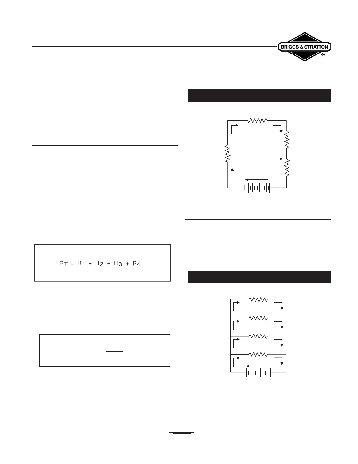
The Series Circuit
A series circuit provides only one path in which current can
flow.A break in any part of the circuit stops current flow in
the entire circuit (Figure 1.19).The following basic laws may
be applied to a series circuit:
• Current flow (in amperes) is the same in every part of
the circuit.
• The total resistance of all resistances (loads) in a
series circuit is the sum of the individual resistances.
• The total voltage across all resistances (loads) in
series is the sum of the voltages across the individual
resistances.
Thus, total resistance may be determined as follows:
Find the voltage drop across each resistor in a series with
the formula E=IR.
Current flow (in amperes) in a series circuit is the same at
every point in the circuit. Find the current flow with the
formula:
The Parallel Circuit
The parallel circuit provides two or more branches in
which current can flow (Figure 1.20). Resistances (loads) in
the individual branches are completely independent of
others in separate branches. If a shorted or open condition
occurs in any branch of the circuit, the remaining branches
may continue operating.
I
=
E
R
13
Figure 1.19 — The Series Circuit
Figure 1.20 — The Parallel Circuit
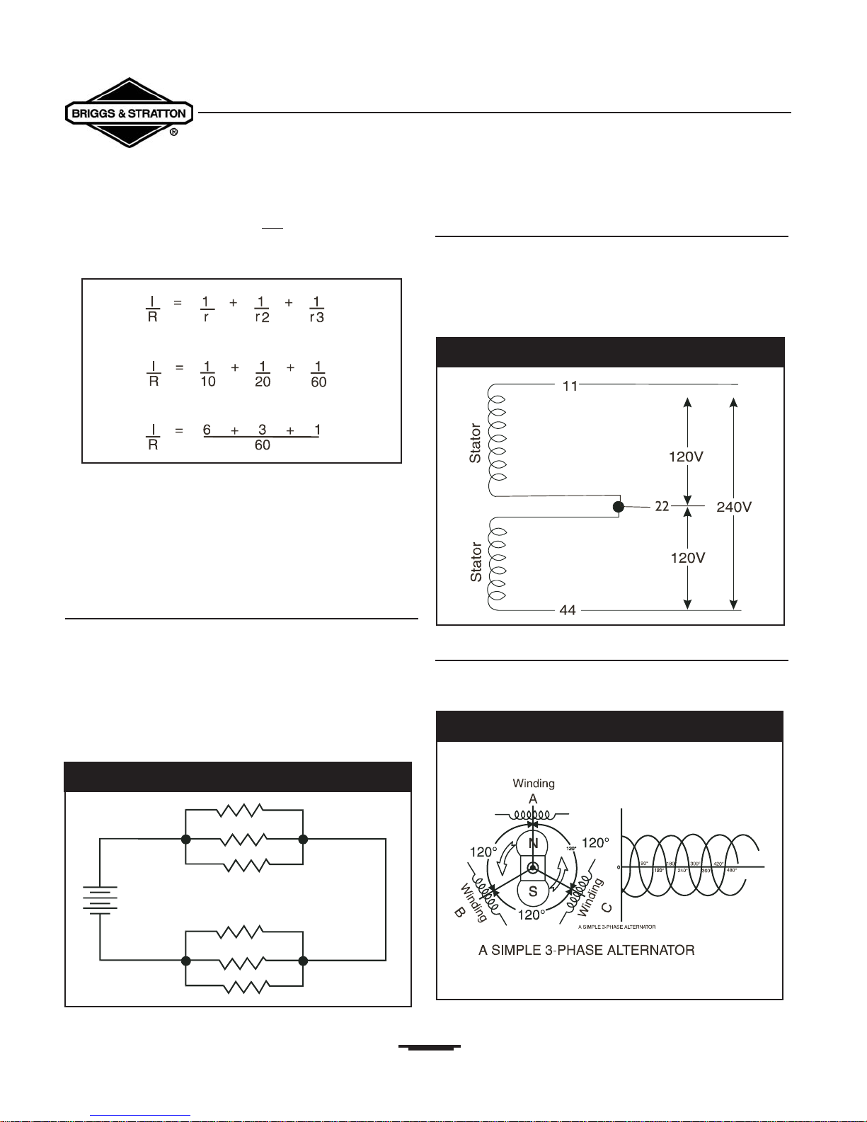
Resistance in a parallel circuit is less
than the resistance of
any of the individual branches or paths.To find total
resistance in any parallel circuit, use the following formula:
The voltage applied to each component in a parallel circuit is
the same as the voltage supplied by the source.The same
voltage will be applied to all components in the circuit.
Total current flow (in amperes) through the branches of a
parallel circuit is the sum of the current flow through
individual components.
The Series-Parallel Circuit
Figure 1.21 shows a series-parallel circuit, in which two
groups of “paralleled” resistors are connected in series.To
find the total resistance of such a circuit, first determine
the resistance of each group. The sum of the two group
resistances is the total circuit resistance.You can treat
the two groups of resistances exactly the same as a pair of
resistances in series.
3-Wire Circuit
Many buildings and AC alternators that have a single phase
output are connected in a 3-wire circuit
(Figure 1.22).The 3-wire circuit provides “dual voltage,”
which means it provides both 120 Volts AC and/or 240 Volts
AC (120VAC and/or 240VAC).
3-Phase Circuits
Three-phase circuits generate three sine waves which are
120 degrees “out-of-phase” with one another (Figure 1.23).
14
Section 1 • Generator Fundamentals
Portable Generator Familiarization & Troubleshooting Guide
Figure 1.22 — Three Wire Circuit
Figure 1.23 — Simple Three-Phase Alternator
Figure 1.21 — The Series-Parallel Circuit
15
Section 1 • Generator Fundamentals
Portable Generator Familiarization & Troubleshooting Guide
A 3-phase circuit has the following advantages:
• When the load is balanced in all three legs of a
3-phase circuit, instantaneous power is constant.This
provides better capabilities for motor starting and
running.
• Current flow in a 3-phase circuit produces a constant
flux density, making it more effective than single phase
circuits for starting and running electric motors.
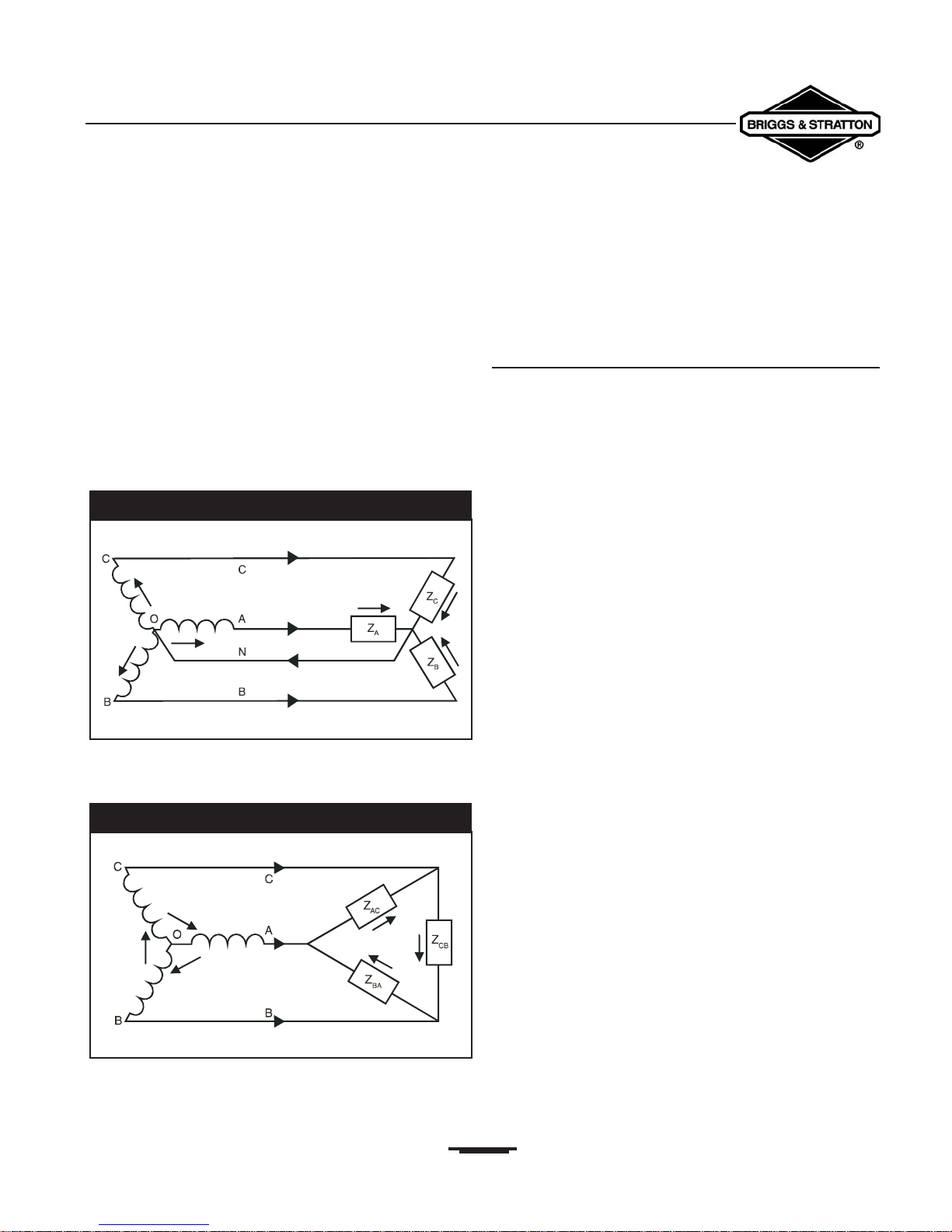
• A wye-connected, 3-phase circuit supplies two
different values of 3-phase voltage in one system.
• To apply 120 Volts to a load, connect it as a
4-wire Wye load, as shown in Figure 1.24.
• To apply 208 Volts to a load, connect the load in
DELTA fashion (Figure 1.25).
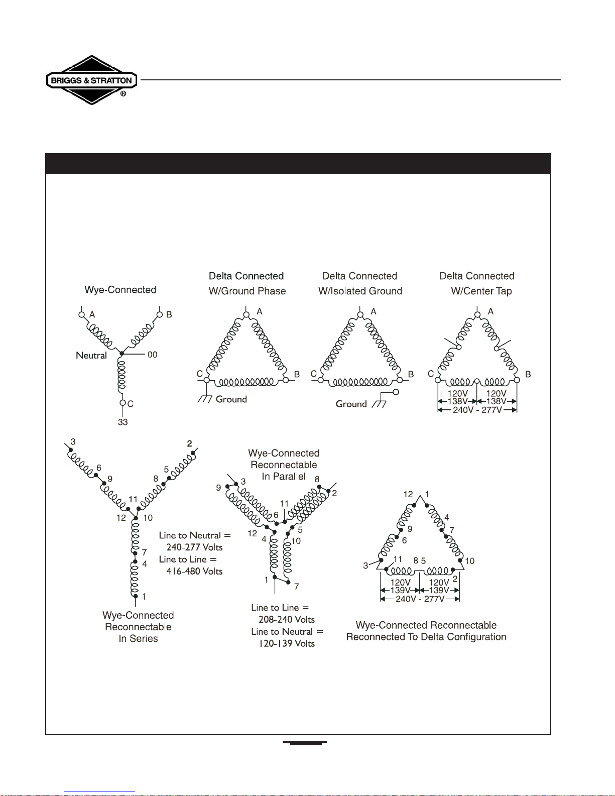
The 3-phase connection systems or circuits may be:
• Wye-Connected
• DELTA-Connected or
• Wye-Connected Re-connnectable (Figure 1.26).
Connections Affecting Circuits
It is necessary to become familiar with some of the terms
used to describe conditions which adversely affect the
operation of electrical circuits. Some of the more common
terms are:
• Open Circuit: An incomplete circuit.
• Partially Open Circuit: A circuit where a high
resistance has developed due to loose or corroded
connections, or a partially broken wire.The resulting
increase in resistance causes current flow to decrease.
• Shorted Circuit: A condition that exists when there is
a DECREASE in resistance across some part of the
circuit. Since electrical current flow “seeks” the path of
least resistance, current will tend to flow across the
shorted section of the circuit.
• Partially Shorted Circuit: A condition where
positive and negative sides of a circuit only contact
slightly, bypassing a small amount of current.
Figure 1.24 — 4-Wire Wye Load (120 Volts Applied)
Figure 1.25 — Load Connected In DELTA Fashion
16
Section 1 • Generator Fundamentals
Portable Generator Familiarization & Troubleshooting Guide
Figure 1.26 — Some Examples of 3-Phase Connection System
17
SIMPLE ALTERNATOR OPERATION
Section 1 • Generator Fundamentals
Portable Generator Familiarization & Troubleshooting Guide
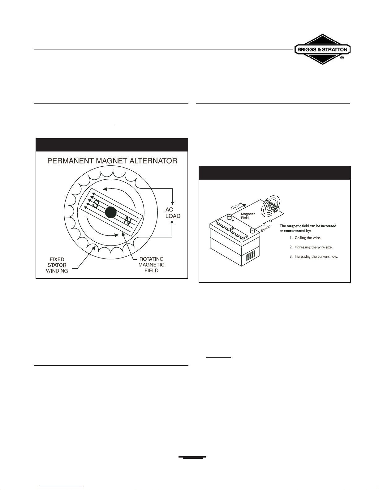
Simple Alternator
In an alternator (Figure 1.27), a revolving magnetic field
called a rotor is moved through a stationary coil of wires
called a stator.This movement induces
an electro-motive
force (EMF) into the stator coils.
As the magnetic lines of flux cut across the stationary
windings, a difference in electrical “potential” is induced into
the stator windings.When a complete circuit is formed (by
connecting a load to the stator windings) current flow
occurs.The current (in amperes) delivered to the load is
affected by:
• The number of wire turns in the stator.
• The strength of the magnetic field in the rotor.
The Stationary Magnetic Field
The number of wire turns in a stator winding are
determined when it is manufactured.A typical stator
assembly may be a single phase type, or a 3-phase type, as
previously discussed.The greater the number of wire turns
in the stator, the greater the induced EMF in the stator.This
is because the magnetic field of the rotor has more wire
turns to cut through on the stator.
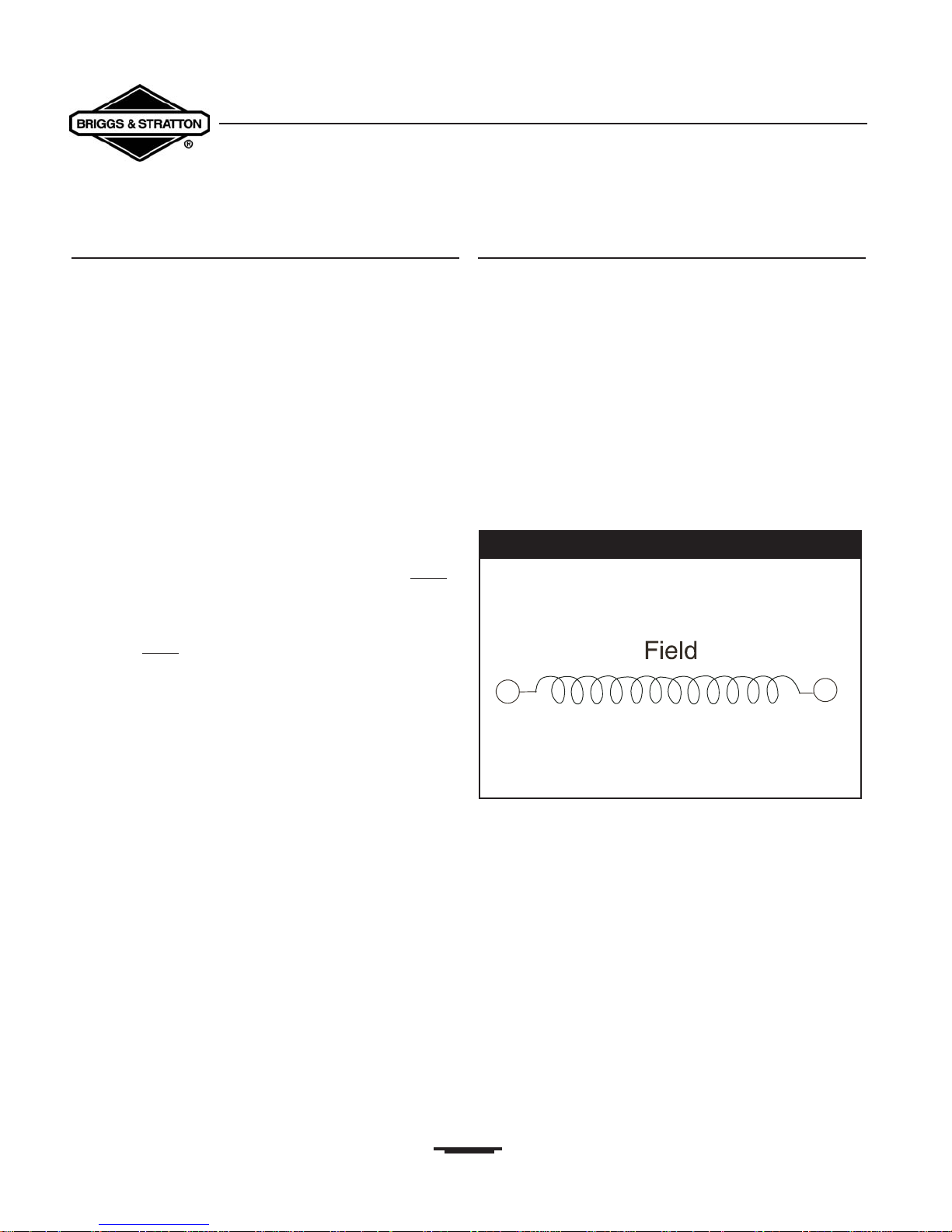
The Revolving Magnetic Field
The rotor is essentially an electro-magnet.The flow of
direct current (DC) through its windings creates a magnetic
field around the rotor core (Figure 1.28).The strength of this
magnetic field can be increased by:
• Forming the rotor wires into a coil.
• Increasing the wire size.
• Increasing the current flow through the rotor wires.
The number of wire turns in a rotor, as well as the wire size,
are established when the rotor is manufactured. When the
alternator is operating, you can vary the strength of the
rotor’s magnetic field by increasing or decreasing the current
flow through the rotor windings.Thus, by controlling
current flow through the rotor windings, the EMF
induced into the stator windings can be regulated
and/or controlled. Because EMF (electro-motive force) is
the equivalent
of voltage, it can then be said that voltage
regulation is accomplished by controlling rotor winding
current flow.
Several methods may be employed to regulate current flow
through rotor windings.They include:
• Direct Excitation.
• Reactor.
• Electronic Voltage Regulator.
• Brushless/Capacitor.
Figure 1.27 — Simple Revolving Field Alternator
Figure 1.28 — Basic Principles Of Operation
Section 1 • Generator Fundamentals
Portable Generator Familiarization & Troubleshooting Guide
18
19
GENERATOR COMPONENTS
Section 2 • Generator Components & Systems
Portable Generator Familiarization & Troubleshooting Guide
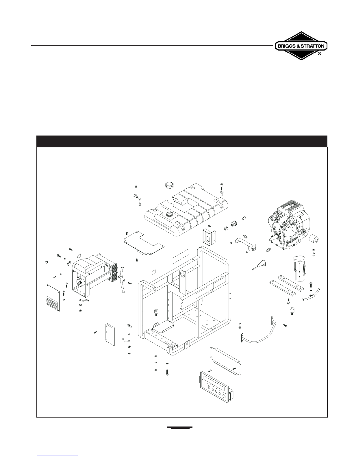
Introduction
Portable generators do not have a large number of parts.
However, these parts are expensive and should not be
replaced needlessly. Replacement of parts as a result of
“guesswork” while troubleshooting is not cost effective and
should be avoided. Figure 2.1 is an exploded view of a typical
portable generator set. Some differences in construction may
exist between various models.
Figure 2.1 — Exploded View of a Typical Generator
Section 2 • Generator Components & Systems
Portable Generator Familiarization & Troubleshooting Guide
Engine Assembly
As a general rule, the engine must deliver approximately 2
horsepower for each 1000 watts (1.0 kW) of generator
output power.With this in mind, the following horsepower
to output ratios are common:
• 2400 watt unit / 5 horsepower
• 3500 watt unit / 7 horsepower
• 4000 watt unit / 8 horsepower
• 5000 watt unit / 10 horsepower
• 8000 watt unit / 16 horsepower
The engine “power takeoff shaft” (PTO), on most portable
generators, is directly connected to the rotor assembly.
Usually, the engine’s PTO shaft is tapered and doesn’t have a
keyway.The rotor assembly is tightened to the shaft by
means of a long rotor bolt.
A mechanical, fixed speed, engine governor maintains actual
engine speed at approximately 3720 RPM for
60 Hertz units or 3100 RPM for 50 Hertz units with no
electrical loads connected to the generator (“no-load”
condition). Rated operating speed is 3600 RPM, at which the
2-pole rotor will supply a rated frequency of 60 Hertz or
3000 RPM for a rated (AC) frequency of
50 Hertz.The slightly high “no-load” speed (3720 RPM) for
60 Hertz units will provide a frequency of about
62 Hertz. Setting the no-load speed slightly high helps
prevent excessive RPM and frequency “droop,” when heavy
electrical loads are applied.
Several different engine manufacturers may be found on the
various
Generac Portable Products®
generator models.They include:
• Briggs & Stratton®
• Tecumseh®
• Kawasaki®
• Honda®
• Robin®
• Generac Power Systems®
Rotor Assembly
A pre-lubricated and sealed ball bearing is pressed onto the
rotor shaft. No additional lubrication is required for the life
of the bearing.The bearing supports the rotor at the “rear
bearing carrier.” Slip rings on the rotor shaft permit
excitation current to be delivered to the rotor windings.
Although residual magnetism is always present in the rotor,
this excitation current flow through the rotor produces a
magnetic field strength that is additive (in addition) to
residual magnetism.
A typical rotor (Figure 2.2) can be a rotating permanent
magnet having no electrical current flow.
In practice, most rotors are a rotating electromagnet with a
direct current flowing through its coiled wires.
Concerning electromagnetism in regards to rotors, these
general statements can be made:
• The strength of the magnetic field is directly
proportional to the number of turns of wire in the
rotor.
• The strength of the magnetic field is directly
proportional to the current (in amperes) flowing
through the rotor windings.
From these statements, we can deduce that the field
strength of the rotor’s magnetic field may be increased by:
• Increasing the number turns of wire in the rotor.
• Increasing he current flow (in amperes) through the
rotor windings.
20
Figure 2.2 — A Typical Rotor Schematic Symbol
Two-Pole Rotors:
A 2-pole rotor has a single north and a single south
magnetic pole. One revolution of the 2-pole rotor creates a
single cycle of alternating current flow in the stator windings.
To determine the rotor speed required for a given (AC)
frequency, use the following formula:
Hertz: The complete set of values through which an
alternating current (AC) repeatedly passes.
Example: An alternator with a 2-pole rotor must produce
a USA standard of 60 Hertz.To find the required driven
speed of the rotor, multiply 60 times 60 to obtain 3600.The
required driven speed of of the rotor is 3600 RPM.
Four-Pole Rotors:
A 4-pole rotor has two south and two north poles.These
rotors provide the same frequency as the 2-pole rotor, but
at half the driven speed of the 2-pole rotor (Figure 2.3).
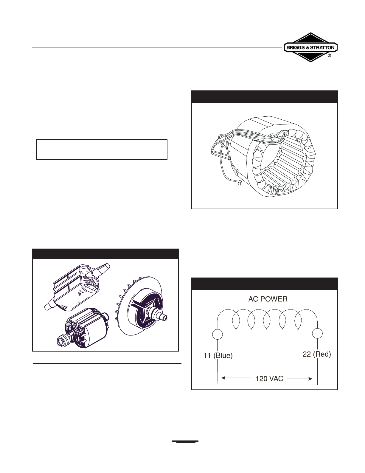
Stator Assembly
The word “stator” means stationary winding. A voltage or
electromotive force (EMF) is induced into the stator by the
action of rotating the magnetic field created by the rotor.A
typical stator assembly is shown in Figure 2.4. Stators differ
greatly, depending on the ratings and design of the specific
alternator on which they will be used.
Typical stators may contain:
• An “excitation” winding (DPE)
• An (AC) “power” winding
• A “battery charge winding” (BCW)
A “single voltage” stator (AC) power winding schematic is
shown in Figure 2.5.
It consists of a single winding, capable of supplying 120VAC
only to a panel receptacle.
21
Section 2 • Generator Components & Systems
Portable Generator Familiarization & Troubleshooting Guide
RPM = Desired Frequency times 60
Figure 2.3 — Typical 2-Pole And 4-Pole Rotors
Figure 2.5 — Single Voltage, 1-Phase Stator Winding
Figure 2.4 — Typical Stator Assembly
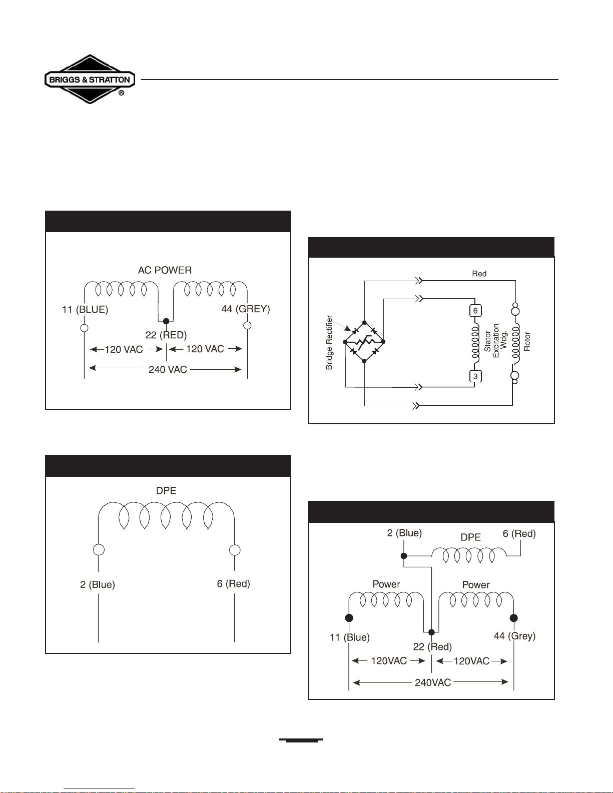
Figure 2.6 represents a “dual voltage” stator (AC) power
winding schematic.
It is made up of two windings and has the ability to supply a
dual output voltage (such as 120VAC and/or 240VAC).
A typical “Displaced Phase Excitation” (DPE) winding is
shown schematically in Figure 2.7.
Output (AC) from this winding is rectified and delivered to
the bridge rectifier rotor windings as direct current (DC).
Stator Excitation Winding
Direct Excited Units: Excitation winding (AC) output is
delivered to a bridge rectifier (Figure 2.8), which converts its
output to direct current (DC).
The rectifier direct current output is delivered to the rotor
windings.
“XL” & “MC” Series Stators
Some “XL” and “MC” series stators are equipped with
excitation” (DPE) windings that interconnect with the stator
(AC) power windings.This is shown in the schematic in
Figure 2.9.
22
Section 2 • Generator Components & Systems
Portable Generator Familiarization & Troubleshooting Guide
Figure 2.6 — Dual Voltage AC Power Winding
Figure 2.7 — Displaced Phase Excitation (DPE)
Figure 2.9 — (AC) / (DPE) Windings (“XL” and “MC”)
Figure 2.8 — Direct Excited Units
Section 2 • Generator Components & Systems
Portable Generator Familiarization & Troubleshooting Guide
NOTE: During tests, this type of stator will show
“continuity” between the (AC) power and (DPE)
windings. Other types of stators are defective if
“continuity” is indicated between the windings.
Always refer to the schematic of the unit being
tested.
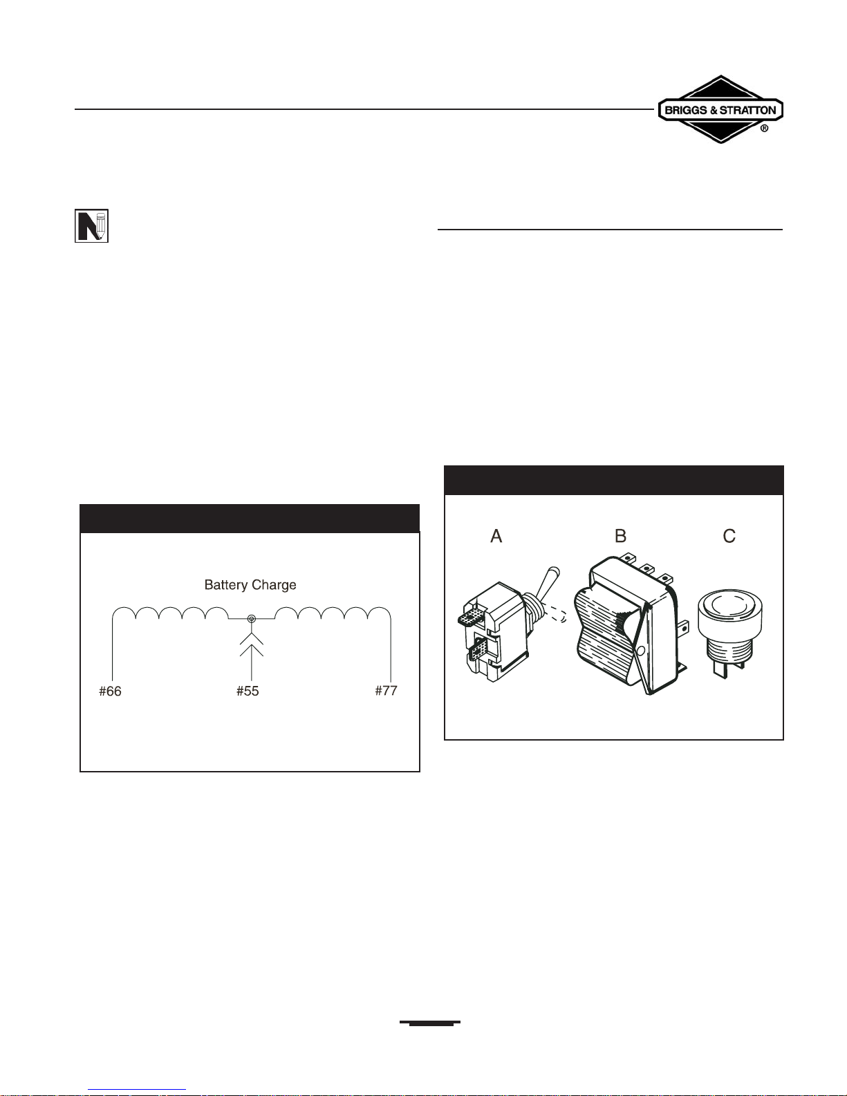
Stator Battery Charge Windings
Some alternator units may be equipped with battery charge
windings (BCW).These units may be used to charge a
connected battery. Figure 2.10 shows a schematic of a typical
battery charging circuit.
The stator battery charge winding delivers a rectified 12
Volts DC (12VDC) through a circuit breaker or fuse to the
connected battery.
Switches
A switch may be defined as a device used to open, close or
divert an electrical circuit.You can actuate switches manually
or automatically. This discussion is devoted solely to manually
operated switches.
Generally, switches are classified according to how they are
actuated, their number of poles and their number of throws.
Actuating Switches
Figure 2.11 shows:
• A Toggle Switch (A)
• A Rocker Switch (B) and
• A Push Button Switch (C).
These switches are named by how they are actuated.
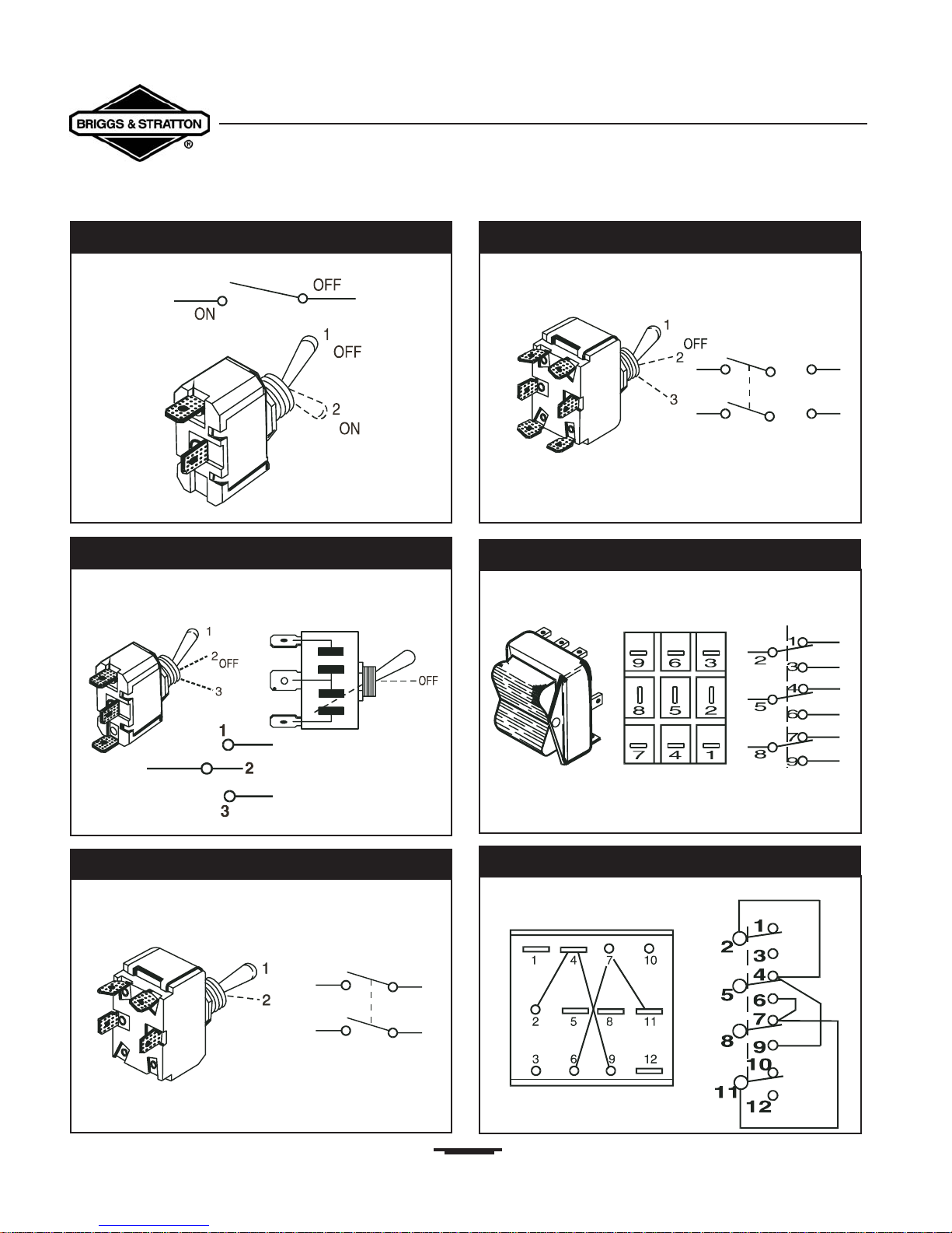
Switches Classified By Poles and Throws
The following types of switches are shown in both pictures
and schematics.
(See Figures 2.12 through 2.17)
• Single Pole, Single Throw (SPST)
• Single Pole, Double Throw (SPDT)
• Double Pole, Single Throw (DPST)
• Double Pole, Double Throw (DPDT)
• Three Pole, Double Throw (3PDT)
• Four Pole, Double Throw (4PDT)
23
Brown
Brown
Black
Figure 2.10 — Stator Battery Charge Circuit
Figure 2.11 — Switches Classified By Actuation
24
Section 2 • Generator Components & Systems
Portable Generator Familiarization & Troubleshooting Guide
Figure 2.12 — Single Pole, Single Throw (SPST)
Figure 2.13 — Single Pole, Double Throw (SPDT)
Figure 2.14 — Double Pole, Single Throw (DPST)
Figure 2.17 — Four Pole, Double Throw (4PDT)
Figure 2.16 — Three Pole, Double Pole (3PDT)
Figure 2.15 — Double Pole, Double Throw (DPDT)
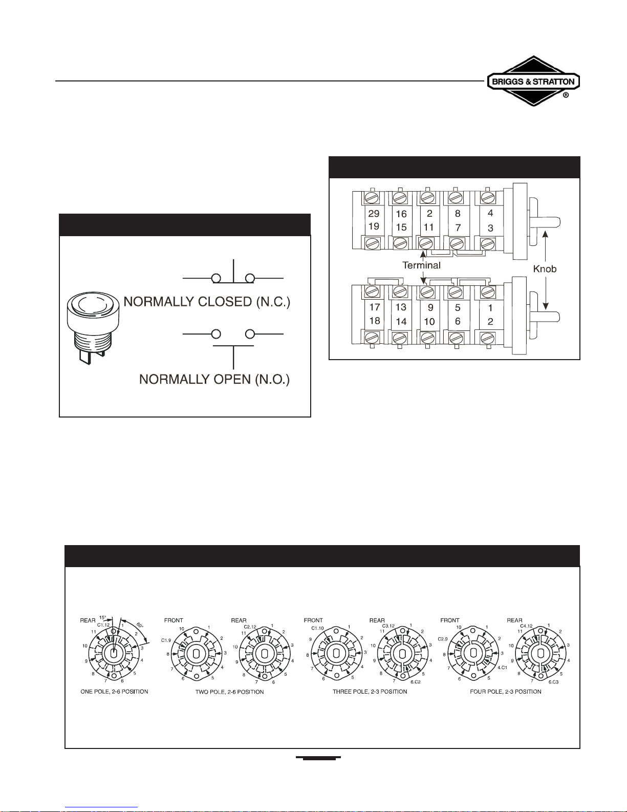
Push Button Switches
Push button switches may be classified generally as
“normally-open” (NO) or “normally-closed” (NC) type
switches. Both types are illustrated in Figure 2.18.
Rotary Switches
Some typical rotary switches are shown in Figure 2.19.
In general, this type of switch may be classified by:
• The number of poles.
• The number of positions.
Figure 2.20 illustrates single-pole, double-pole, 3-pole and
4-pole rotary switches.
25
Section 2 • Generator Components & Systems
Portable Generator Familiarization & Troubleshooting Guide
Figure 2.18 — Push Button Switches
Figure 2.20 — Examples Of Rotary Switch Classifications
Figure 2.19 — Some Typical Rotary Switches
Section 2 • Generator Components & Systems
Portable Generator Familiarization & Troubleshooting Guide
Protective Switches
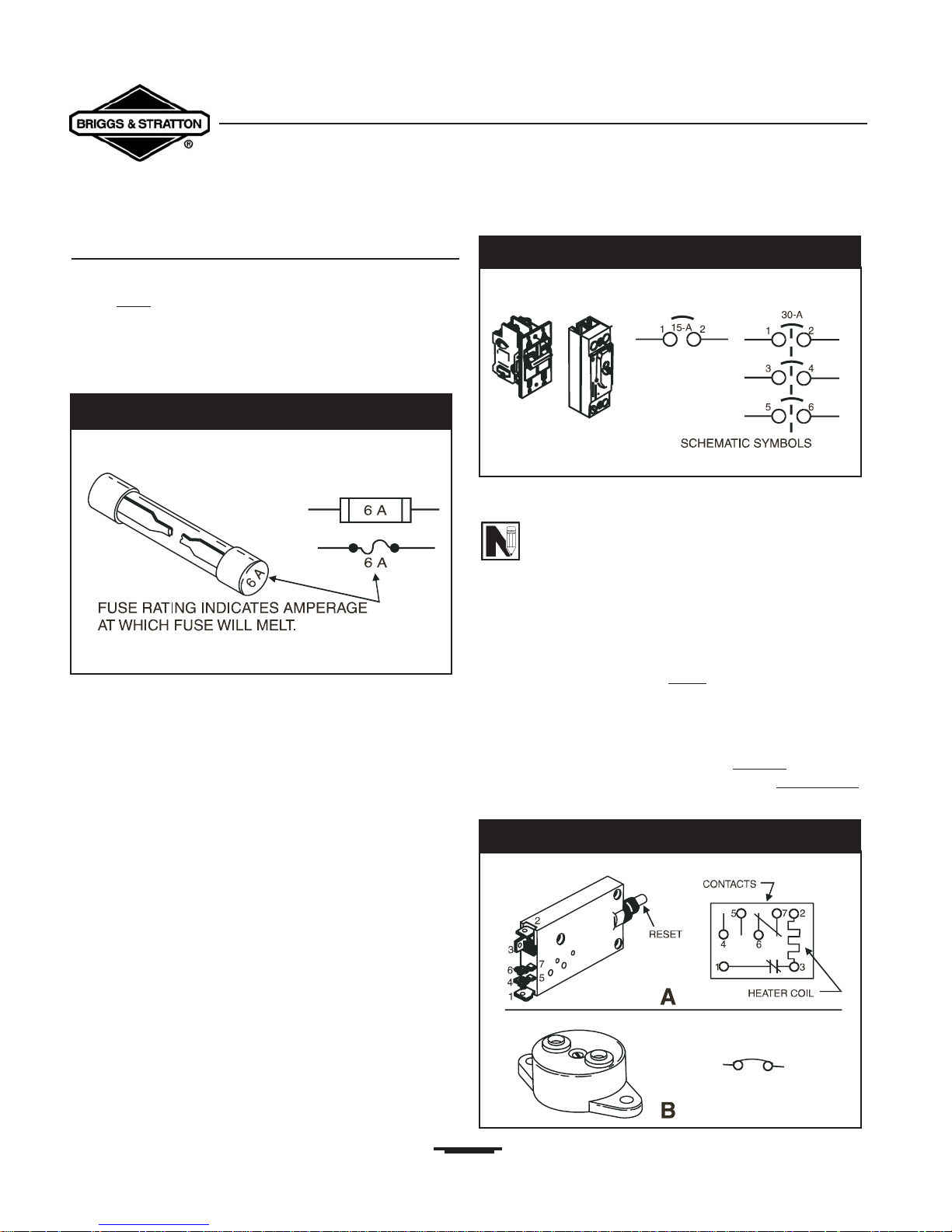
Fuses
A fuse could
be called a switch because it functions to open
an electrical circuit when current flow becomes excessive.
The fuse in Figure 2.21 is a strip of metal with a known
melting point that has been installed in series with the circuit
it is meant to protect.
Should current flowing through the fuse exceed a specific
value, the fuse element (strip of metal) melts which opens
the circuit. Generally, fuses are rated at the current value (in
amperes) at which its element will melt open.
Circuit Breakers
Circuit breakers (Figure 2.22) protect one or more circuits
against overloads or short circuits.
One type of circuit breaker consists of an electromagnet
with coil windings that are in series with the circuit to be
protected.When current flow exceeds a pre-determined
value, the coil’s magnetic field becomes strong enough to
open a set of contact points and open (or break) the circuit
before damage can be occur.
NOTE: A “circuit breaker” may be reset manually
while a “fuse” must, generally, be replaced.
Thermal Switches
Thermal switches react to changes in temperature. One type
of thermal switch consists of a fine metal strip in which two
different metals having different expansion rates are welded
together. When the two different metals are heated, the
metal strips bend, which then opens
(breaks) a set of
contacts.
Figure 2.23 illustrates two different types of thermal
switches.
The switch shown in “A” must be reset man
ually once it has
been tripped. In ”B,” the thermal switch resets automatically
after the metal has cooled to a pre-established temperature.
26
Figure 2.21 — A Typical Fuse
Figure 2.23 — Examples of Thermal Switches
Figure 2.22 — Typical Circuit Breakers
Section 2 • Generator Components & Systems
Portable Generator Familiarization & Troubleshooting Guide
Some stators may have a thermal protector imbedded in
their wire windings and electrically connected in series with
the excitation winding output to the voltage regulator.This
thermal switch opens
at a pre-determined temperature to
terminate excitation current output to the rotor.The switch
closes automatically when the internal stator temperature
decreases to a safe value (Figure 2.24).
Another type of thermal switch may sense engine coolant
temperature.This switch is the “normally-open” (NO) type
and closes
if coolant temperature exceeds a pre-determined
safe value. It grounds the engine’s ignition circuit and causes
the engine to shut down.
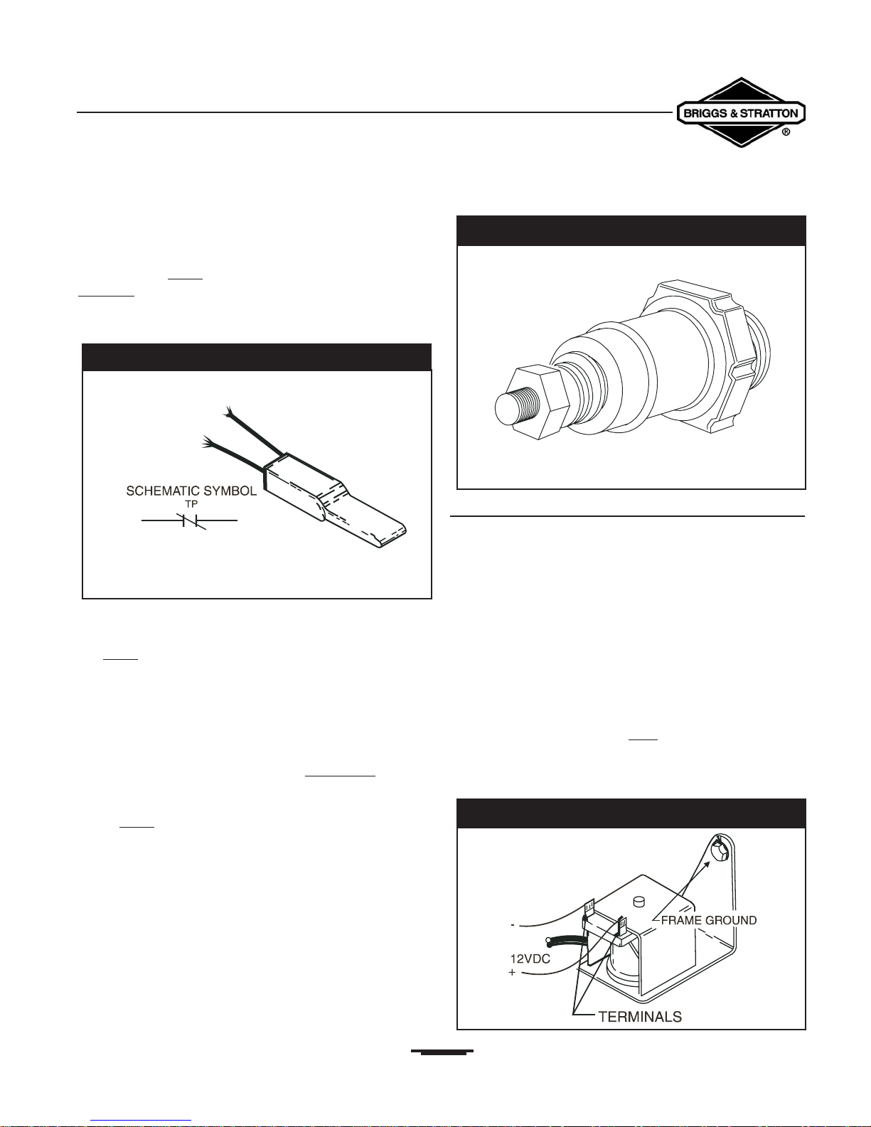
Pressure Switches
One example of a pressure switch is the low oil pressure
shutdown switch used on some generator engines.This type
of switch is normally-closed (NC), and is held open
by
engine oil pressure during engine operation. Should engine
oil pressure drop below a pre-determined safe value, the
switch closes to ground the engine ignition circuit, causing
the engine to shut down (Figure 2.25).
Solenoids
A solenoid is a device used to convert electrical energy into
mechanical movement. It is based on the principle that when
current flows through a conductor, a magnetic field is
created around that conductor. Solenoids may be used in the
following applications:
• Fuel shutoff valves
• Electric chokes
• Engine throttle controls
• Engine anti-dieseling devices.
Fuel Shutoff Valves
This type of valve is energized open
by a 12VDC signal
during engine cranking and running.A spring causes it to
close when the (DC) signals are removed as the engine
shuts down (Figure 2.26).
27
Figure 2.24 — Thermal Protector
Figure 2.25 — Typical Pressure Switch
Figure 2.26 — Typical Fuel Shutoff Valve
Engine Throttle Control
Some generator units may be equipped with an automatic
idle (throttle) control device. This device uses a solenoid
to pull the carburetor throttle lever against its idle
stop when the alternator unit is not powering any
electrical loads. When an electrical load is connected to
the generator, the solenoid is de-energized and the engine
governor takes control of engine speed.Thus, the unit
operates at its governed speed only when electrical loads
are connected and turned ON.The engine decelerates to
idle speed when loads are disconnected (Figure 2.27).
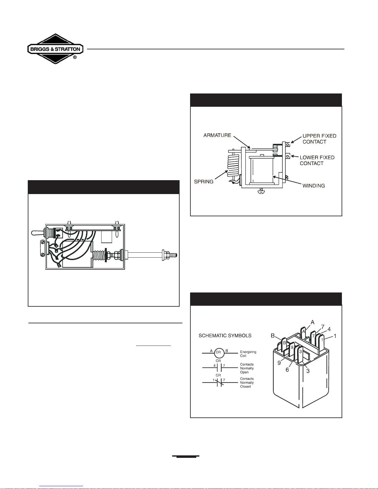
Relays
You can compare relays to solenoids because a relay is an
electromagnet that also creates mechanical movement. The
relay, however, utilizes its magnetic field to open or close
a
set (or sets) of electrical contacts.
A typical relay operates as follows (Figure 2.28):
• With no voltage applied to the relay winding, the spring
holds the armature contacts against the upper fixed
contact.
• When current flow is applied to the winding, a magnetic
field is created.The winding becomes an electromagnet
that overcomes spring tension and pulls the armature
contacts down against the lower fixed contact.
• Removing the current collapses the magnetic field.The
spring tension then acts to pull the armature contacts
to their original position against the upper fixed
contacts.
A relay thus functions as an electrically actuated switch to
open or close a circuit.
A typical relay is shown in Figure 2.29, along with the
schematic symbols for the relay’s winding (energizing coil)
and contacts.
The terms “normally open” (NO) and “normally closed”
(NC) refer to the condition of the contacts when no
current is flowing through the energizing coils.
28
Section 2 • Generator Components & Systems
Portable Generator Familiarization & Troubleshooting Guide
Figure 2.27 — Typical Idle Control Solenoid
Figure 2.29 — Typical Relay With Schematic Symbols
Figure 2.28 — Construction Of A Typical Relay
 Loading...