

Briggs & Stratton 276535, 84000 Series Repair Manual
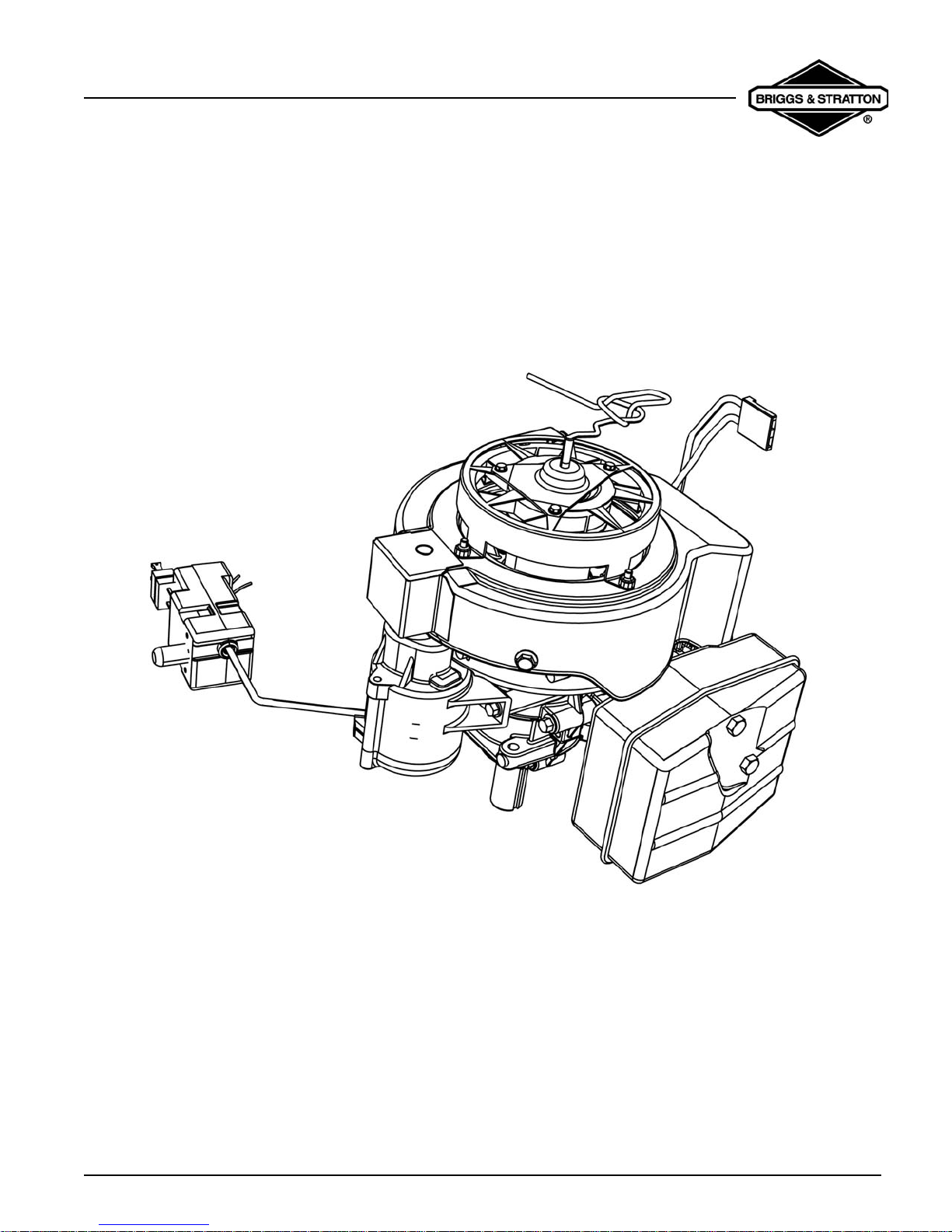
2-Cycle Snow Engine
2-CYCLE SNOW ENGINE
REPAIR MANUAL
MANUAL NUMBER: 276535
0
2-Cycle Snow Engine
SAFETY INFORMATION
The Briggs & Stratton engine is made of the finest
material in a state-of-the-art manufacturing facility.
Please understand that Briggs & Stratton sells engines
to original equipment manufacturers. It also sells to
others in the distribution chain who may sell to the
ultimate consumer, an equipment manufact urer, anot her
distributor or a dealer. As a result, Briggs & Stratton does
not necessarily know the application on which the engin e
will be placed. For that reason, carefully read and
understand the operating instructions of the equipment
before you repair or operate.
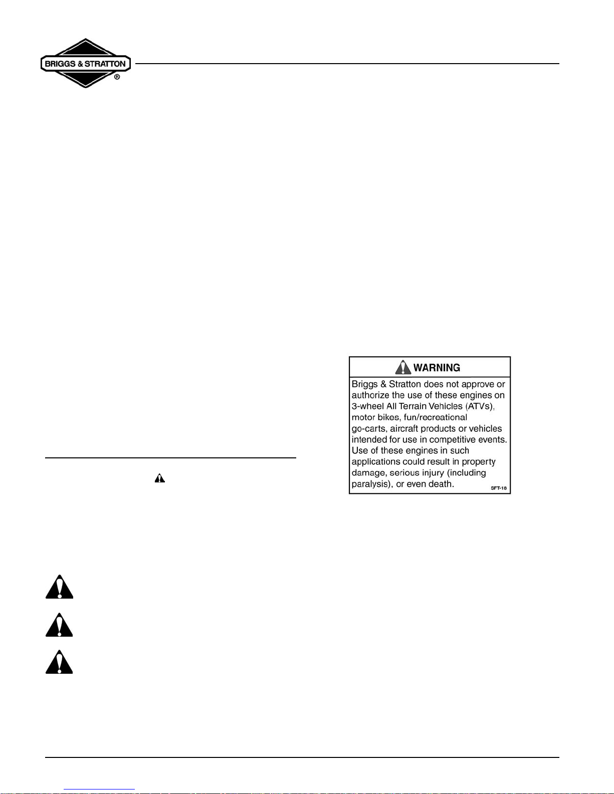
You should also understand that there are equipment
applications for which Briggs & Stratton does not
approve the use of its engines. Briggs & Stratton e ngines
are not to be used on vehicles with less than 4 wheels.
This includes motor bikes, aircraft products and all
terrain vehicles. Moreover, Briggs & Stratton does not
approve of its engines being used in competitive events.
FOR THAT REASON, BRIGGS & STRATTON
ENGINES ARE NOT AUTHORIZED FOR ANY OF
THESE APPLICATIONS. Failure to follow this warning
could result in death, serious injury (including paralysis)
or property damage.
• Prior to work, read and understand the section(s) of
this manual that pertain to the job. Follow all safety
warnings.
• Wear suitable eye protection.
• Prevent accidental starting by removing spark plug
wire from spark plug when servicing engine or
equipment. Disconnect negative battery terminal if
equipped with electric starting system.
• Periodically clean engine . K eep go v ernor parts free
of dirt, grass and other debris which can affect
engine speed.
• Always use fresh gasoline. Stale fuel can gum
carburetor and cause leakage.
• Check fuel lines and fittings frequently for cracks or
leaks and replace if necessary.
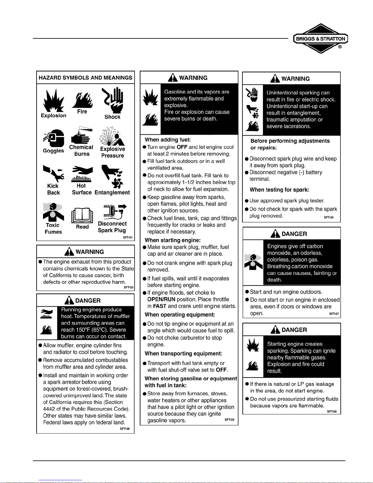
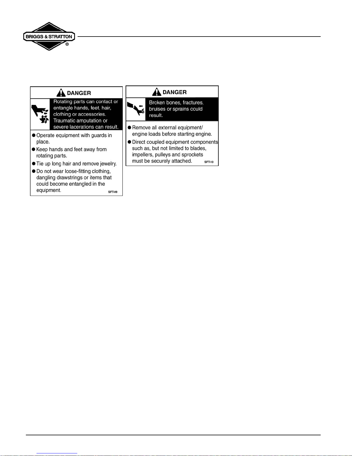
IN THE INTEREST OF SAFETY
The safety alert symbol ( ) is used to identify safety
information about hazards that can result in personal
injury.
A signal word (
with the alert symbol to indicate the likelihood and the
potential severity of injury. In addition, a hazard symbol
may be used to represent the type of hazard.
DANGER indicates a hazard which, if not
avoided,
WARNING indicates a hazard which, if not
avoided,
CAUTION indicates a hazard which, if not
avoided, might result in minor or moderate injury.
CAUTION: When this signal word is used without the
alert symbol, it indicates a situation that could result in
damage to the engine.
DANGER, WARNING, or CAUTION) is used
will result in death or serious injury.
could result in death or serious injury.
i
2-Cycle Snow Engine
ii
2-Cycle Snow Engine
iii

2-Cycle Snow Engine
Table of Contents
2-CYCLE SNOW ENGINE
REPAIR MANUAL .....................................0
SAFETY INFORMATION ...........................i
In The Interest Of Safety ...............................i
SECTION 1
GENERAL INFORMATION .......................1
TWO-CYCLE ENGINE THEORY .................1
IGNITION COIL OPERATION ......................2
REWIND STARTER .....................................3
ELECTRIC START (OPTIONAL) .................3
RECOMMENDED MAINTENANCE
SCHEDULE ..................................................3
25 Hours ............................... ... ... .... ... ..............3
50 Hours ............................... ... ... .... ... ..............3
REPLACE SPARK PLUG .............................4
CLEANING THE EXHAUST SYSTEM .........4
SECTION 2
TROUBLESHOOTING ..............................5
GENERAL TROUBLESHOOTING
INFORMATION ............................................5
Systematic Check ............................................5
Check Ignition ................ .... ... ........................... 5
Engine Misfires ................................................ 5
Check Carburetion .......................................... . 6
Check Compression ....................................... . 6
EQUIPMENT AFFECTING ENGINE
OPERATION ................................................6
Hard Starting, Kickback, or Will Not Start ........ 7
Vibration ............................. ............................. .7
Power Loss .................... .... ... ........................... 7
STARTER MOTOR FAILS TO TURN .........7
Power not reaching product. ............................ 7
Starter switch malfunction. ............................... 7
Engine has seized. ..........................................7
Starter motor has failed. ..................................7
SECTION 3
ENGINE DISASSEMBLY ..........................9
REMOVE SHROUD .....................................9
REMOVE CARBURETOR ............................9
REMOVE FLYWHEEL ................................10
REMOVE OPTIONAL 120V STARTER ......10
REMOVE MUFFLER ..................................10
REMOVE IGNITION MODULE ...................11
ENGINE DISASSEMBLY ...........................11
SECTION 4
ENGINE OVERHAUL ..............................13
ENGINE INSPECTION & REPAIR .............13
Flywheel and Key ............................. .... ..........13
Bearings .........................................................13
Crankcase ......................................................13
Check Cylinder Bore .. ... ... .... ... ... .................... 1 3
Piston And Rings .................. ... ... ... ... ..............14
Piston Pin (Wrist Pin) And Connecting Rod .....4
CARBURETOR DISASSEMBLY ................15
CARBURETOR CLEANING &
INSPECTION ..............................................17
CARBURETOR ASSEMBLY ......................17
REWIND STARTER Replacement .............20
Rope Replacement .. ... ... ... .... ... .......................20
(OPTIONAL) ELECTRIC STARTER
REPLACEMENT .........................................20
SECTION 5
ENGINE ASSEMBLY ..............................21
ASSEMBLE PISTON AND
CONNECTING ROD ..................................21
INSTALL PISTON RINGS ..........................21
Engine Model 84130 & 84230 ........................21
Engine Model 84330 .....................................21
iv

INSTALL PISTON AND
CONNECTING ROD ..................................22
INSTALL CONNECTING ROD BEARINGS 23
INSTALL CRANKSHAFT AND
CONNECTING ROD ..................................23
INSTALL OIL SEALS ..................................24
INSTALL CRANKCASE COVER ................25
INSTALL CYLINDER HEAD .......................25
INSTALL IGNITION COIL AND
FLYWHEEL ................................................25
INSTALL AIR VANE AND GOVERNOR .....26
INSTALL INTAKE MANIFOLD AND
CARBURETOR ..........................................27
CHECK GOVERNOR OPERATION ...........27
INSTALL MUFFLER ...................................28
INSTALL BLOWER HOUSING ...................28
2-Cycle Snow Engine
Table of Contents
SECTION 6
FINAL ADJUSTMENTS &
SPECIFICATIONS ..................................29
GOVERNOR ADJUSTMENTS ...................29
SPECIFICATIONS ......................................30
COMMON SPECIFICATIONS ....................30
STANDARD AND REJECT DIMENSIONS 31
v
2-Cycle Snow Engine
Section 1 - General Information
SECTION 1
GENERAL INFORMATION
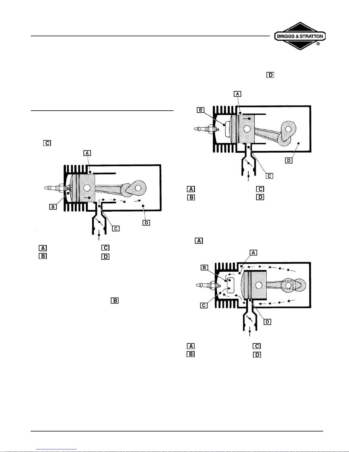
TWO-CYCLE ENGINE THEORY
In a piston-ported engine, the fuel mixture enters the
crankcase through a port that comes directly from the
carburetor (commonly referred to as a “third port”), See
item figure 1.
Intake Ports Closed
Ignition
Third Port Open
Partial Vacuum
compresses the fuel mixture (Item Figure 2) that is on
the bottom side of the piston in the crankcase.
Intake Ports Closed
Exhaust Port Opening
Third Port Closed
Pressure Building Up
Fig. 2
Near the bottom of its travel, the piston uncovers the
pressure transfer port and allows this compressed fuel/
air mixture to expand into the combustion chamber
(Item Figure 3).
Fig. 1
At about 28° before top-dead-center (BTDC), the spark
plug ignites and forces the piston away from the spark
plug. As the piston moves away from the spark plug, it
exposes the exhaust port (Item Figure 2) and the
expanding exhaust gases escape. As the piston
continues to move away from the spark plug, it
Intake Ports Open
Exhaust Port Open
Fresh Fuel Change
Third Port Closed
Fig. 3
Now the piston begins its travel in the opposite direction
and first closes off the transfer po rt and then the exh aust
Page 1
2-Cycle Snow Engine
Section 1 - General Information
port. As it continues, it compresses the fuel mixture in
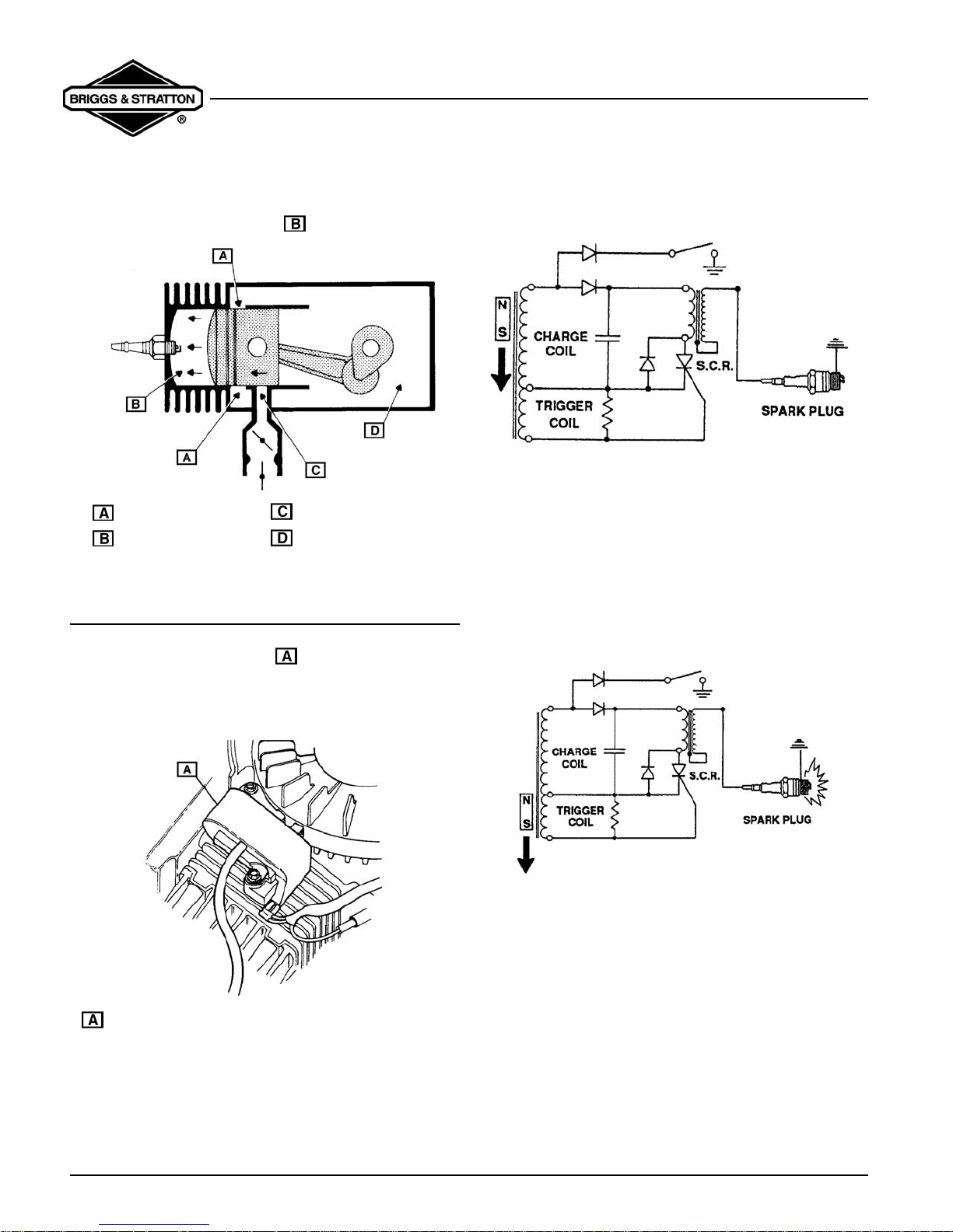
the combustion chamber (Item Figure 4).
Intake Ports Closed
Compression
Third Port Closed
Partial Vacuum
Fig. 4
IGNITION COIL OPERATION
The ignition coil system (Item Figure 5) is
breakerless and contains electronic components that
replace mechanical points and related accessories (such
as a breaker cam, spark advance assembly, etc.).
voltage is converted by a rectifier into a DC signal, which
is then stored in a capacitor (Figure 6).
Fig. 6
When the silicone-controlled rectifier (SCR) is triggered,
up to 200 volts DC, stored in the capacitor, travels to the
spark coil. Here it is stepped up to as much as 25,000
volts and is discharged across the electrodes of the
spark plug (Figure 7).
Ignition timing (when the SCR is triggered) is determined
by the flywheel magnet and the keyways in the flywheel
and crankshaft. Damage to any of these parts will affect
the ignition timing.
Ignition Coil Module
Fig. 5
As the flywheel magnet passes the ignition coil module,
an AC voltage is induced into the charge coil. This AC
Page 2
Fig. 7
2-Cycle Snow Engine
Section 1 - General Information
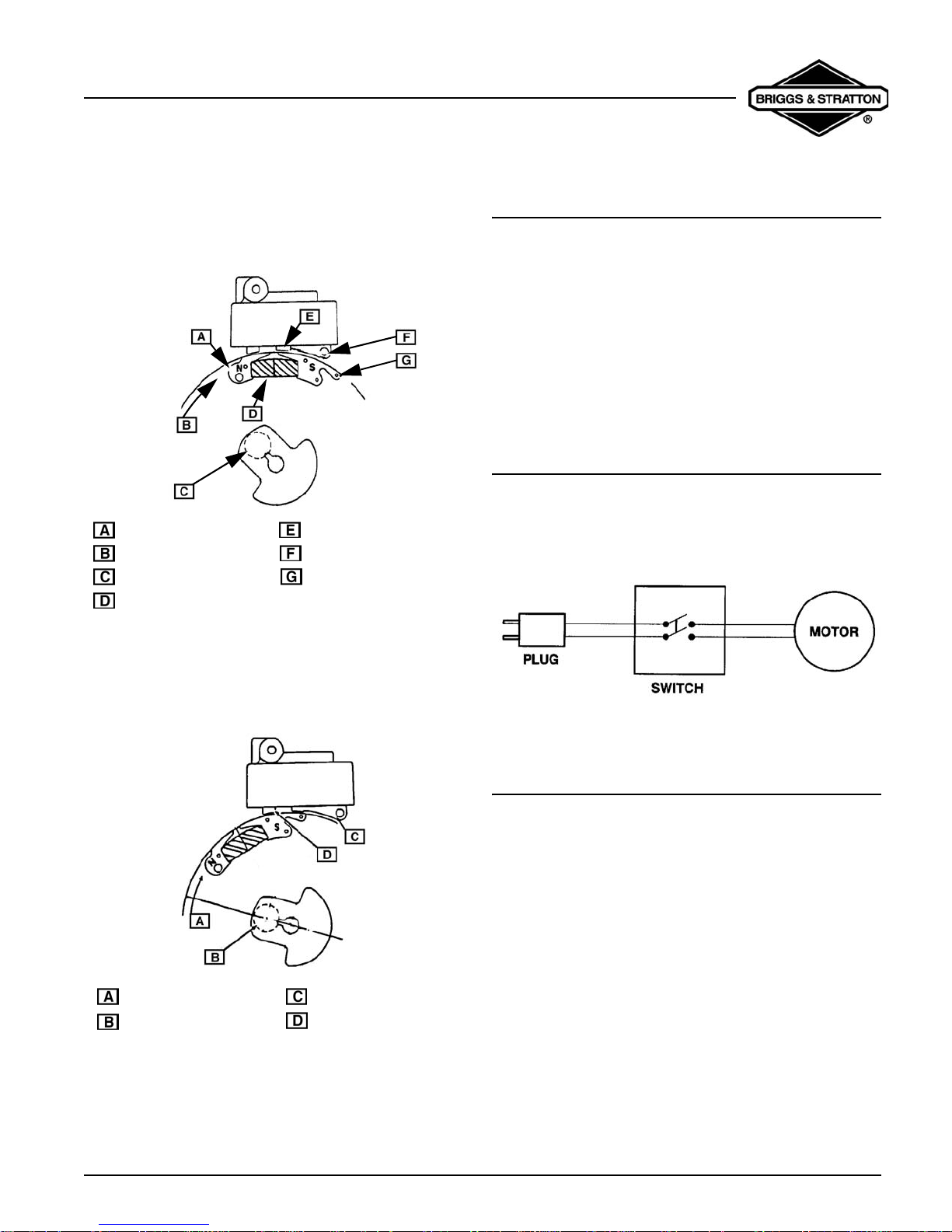
At slower speeds, the flywheel magnet induces a smaller
charge in the trigger coil. This action triggers the (SCR),
enabling easier starting in a “retarded firing position”
-about 5° before top dead center (BTDC). See f igure 8.
Pole Shoe
Flywheel Rotation
Crankshaft at 5° BTDC
Magnet
Starting Leg
Charging Leg
Pole Shoe
Fig. 8
REWIND STARTER
The rewind starter operates through a retainer/friction
disc and two engagement dogs that extend from the
center of the rewind starter and engage the inside of the
starter hub on the flywheel. The engagement dogs
contact the starter hub when the rewind rope is pulled.
When the engine starts, the starter cup exceeds the
speed of the recoil starter causing the ramps on the
inside of the cup to contact the back side of the starter
dogs, pushing them inward. When the starter rope is
relaxed, spring tension retracts the dogs .
ELECTRIC START (OPTIONAL)
The electric start models use a 120VDC starting system.
When the starter is supplied with voltage, the helical
shaft spins to force the pinion gear out on the shaft and
engage the ring gear (Figure 10).
At faster speeds (about 800 RPM), the fl ywheel magnets
induce a large enough charge in the trigger coil to t rigger
the SCR in the “advanced firing position,” -about 28°
BTDC (Figure 9).
Flywheel Rotation
Crankshaft at 25° BTDC
Charging Leg
Running Leg 25°
Advanced
Fig. 9
Fig.10
RECOMMENDED MAINTENANCE
SCHEDULE
25 Hours
• Clean/replace or re-gap spark plu g
50 Hours
• Clean exhaust ports
• Check for fuel leakage
Page 3
2-Cycle Snow Engine
Section 1 - General Information
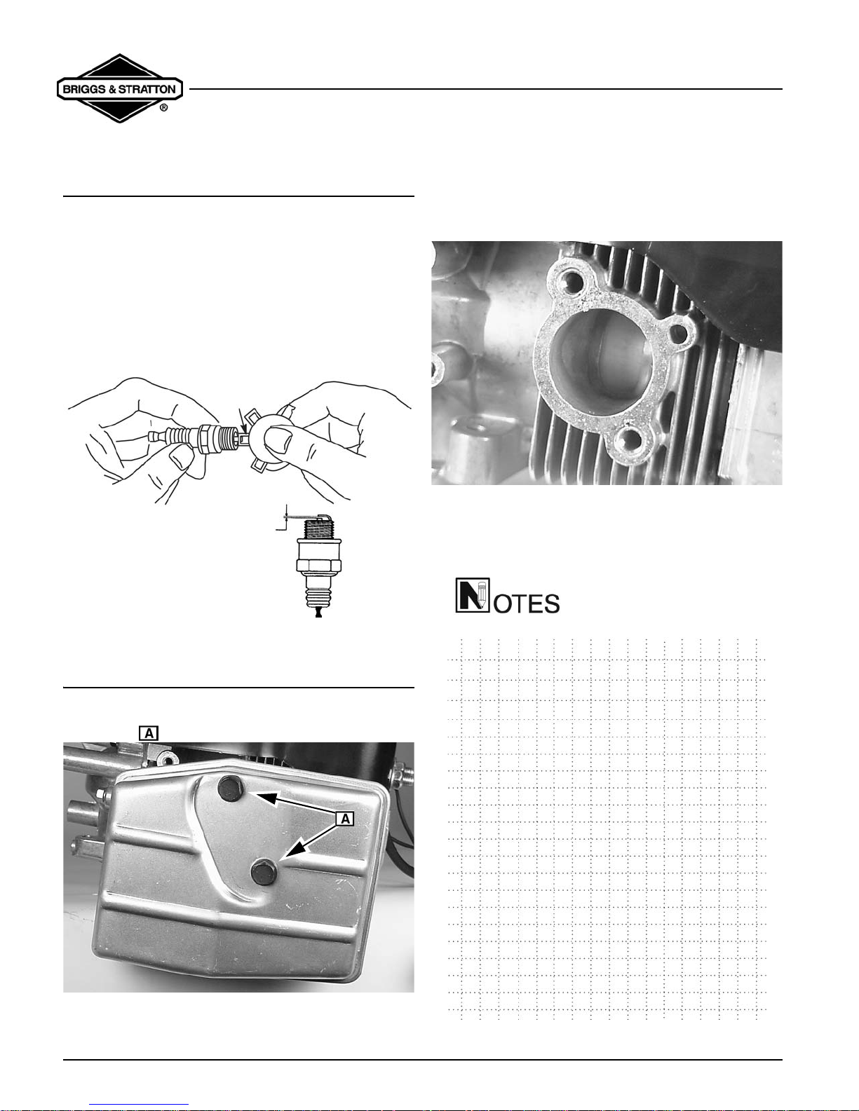
REPLACE SPARK PLUG
Replace spark plug every year. Replace spark plug if
electrode is burned away or if the porcelain is cracked. A
spark plug that is dirty, pitted, carbon covered or has
worn electrodes may cause hard starting and/or poor
operation. Clean plug with a wire brush. Do not sand
blast. Use
gap (Figure 11) at
plug to
NGK BPMR 4A or equivalent. Set spark plug
.028-.032 in. (.71-.81mm). Torque spark
150-200 lb-in. (17-23 Nm).
.28-.032 in.
(.71 - .81mm)
2. Inspect exhaust port (Figure 13). If cleaning is
necessary, rotate piston to cover exhaust port,
and scrape carbon from exhaust port area. Use
wood only to clean this area.
BST01-83
Fig. 13
3. Install the muffler and torque the bolts to 80 lb-in.
(9Nm)
.
Fig. 11
CLEANING THE EXHAUST SYSTEM
1. Remove the muffler (Figure 12) by removi ng the
bolts shown. Clean as needed.
BST01-82
Fig. 12
Page 4
2-Cycle Snow Engine
Section 2 - Troubleshooting
SECTION 2
TROUBLESHOOTING
GENERAL TROUBLESHOOTING
INFORMATION
Most complaints concerning engine operation can be
classified as one or a combination of the following:
• Will not start
• Hard starting
• Lack of power
• Runs rough
• Vibration
NOTE: What appears to be an engine
malfunction may be a fault of the powered
equipment rather than the engine. If equip ment is
suspect, see Equipment Affecting Engine
Operation.
Systematic Check
If the engine is hard starting or will not start and the
cause of malfunction is not readily apparent, perform a
systematic check in the following order:
• Ignition
• Carburetion
• Compression
This check-up, performed in a systematic manner, can
usually be done in a matter of minutes. It is the quickest
and surest method of determining the cause of failure.
observed at the tester gap, you may assume the ignition
system is functioning satisfactorily.
Fig. 14
NOTE: Engines equipped with capacitive
discharge ignition system will still display spark
at tester with a partially or fully sheared flywheel
key. A partially sheared flywheel key will affect
ignition timing and engine performanc e.
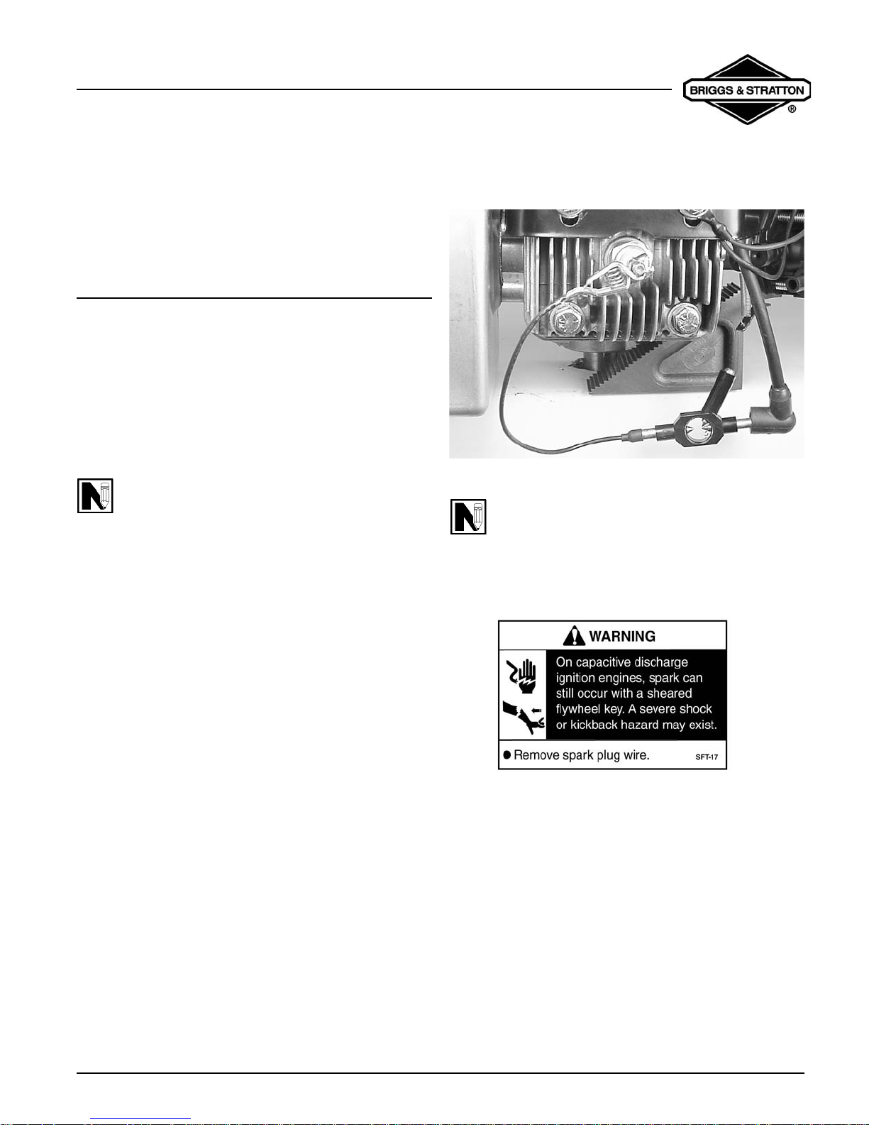
Check Ignition
With stop switch in
installed, attach a
lead and ground the other end of the tester as shown in
figure 14. Operate the starter. If a strong , steady spar k is
ON/RUN position and spark plug
#19368 ignition tester to the spark plug
If spark does not occur look for:
• Shorted stop switch
• Shorted ground wire
• Incorrect armature air gap
• Armature failure
Engine Misfires
If engine runs but misses during operatio n, a quick check
to determine if ignition is or is not at fault can be made by
installing Tool
and spark plug (Figure 15). A spark miss will be obvious
#19368 tester between the spark plug lead
Page 5
2-Cycle Snow Engine
Section 2 - Troubleshooting
when the engine is running. If the spark looks good in the
tester but the engine misses, try a new spark plug.
WE NEED TO FIND A TESTER!
Fig. 15
NOTE: A leak at the cylinder crankcase
mounting surfaces or oil seals can create a lean
fuel mixture resulting in low power or a miss.
Check for leakage at these areas.
Check Carburetion
Before checking carburetion, be sure the fuel tank has
an ample supply of fresh, clean gasoline. Make sure
throttle and choke controls are properly adjusted.
If engine cranks but will not start, remove and inspect the
spark plug.
If plug is wet, look for:
• Over choking
• Water in fuel
• Float needle valve stuck open
• Fouled spark plug
If plug is dry, look for:
• Leaking carburetor mounting gaskets.
• Gummy or dirty carburetor, fuel filter, fuel lines or
fuel tank
• Float needle valve stuck shut
• Plugged fuel cap vent
A simple check to determine if the fuel is getting to the
combustion chamber through the carburetor is to remove
the spark plug and pour a small quantity of fuel
(1 teaspoon or 5 mil.) through the spark plug hole.
Replace the plug. If the engine fire s a few times and t hen
stops, look for the same conditions as for a dry plug.
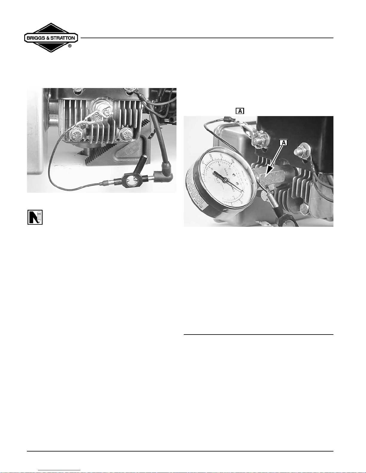
Check Compression
Connect spark plug wire to long terminal of tester, Tool
#19368 and ground tester to engine with alligator clip.
To check compression, remove the spark plug and install
compression tester (Figure 16).
Fig. 16
Crank the engine using the rewind starter. Continue
cranking until meter reading stabilizes. The meter
reading should be approximately
compression is below
• Loose cylinder head bolts
• Blown head gasket
• Worn bore and/or rings
• Broken connecting rod
80 PSI (5.5 bar), look for:
115 PSI. (7.9 bar). If
EQUIPMENT AFFECTING ENGINE
OPERATION
Frequently, what appears to be a problem with engine
operation, such as hard starting, vibration, etc., can be
caused by the equipment being powered rather than the
engine itself. Since many varied types of equipment are
powered by Briggs & Stratton engines, it is not possible
to list all of the various conditions that may exist. Listed
are the most common effects of equipment problems,
and what to look for as the most common cause.
Page 6
 Loading...