

Briggs & Stratton 7800950-00, 7800950-01, 7800952-01, 7800953-00, 7800951-00 Operator's Manual
...
Not for
Reproduction
en
Operator’s Manual
es
fr
Manual del operador
Manuel d’utilisation
Copyright © Briggs & Stratton Power Products Group, LLC
Milwaukee, WI USA. All Rights Reserved
7106180USCN
Revision C

Not for
Reproduction
2
Not for
Reproduction
en
Thank you for purchasing this quality-built Rear Engine
Rider. We’re pleased that you’ve placed your confidence
in the brand. When operated and maintained according
to the manuals, your product will provide many years of
dependable service.
The manuals contain safety information to make you aware
ofthe hazards and risks associated with the unit and how
to avoid them. This Rear Engine Rider was designed to be
used as described in operator’s manual and is not intended
for any other purpose. It is important that you read and
understand the instructions thoroughly before attempting
to start or operate this equipment. Save these original
instructions for future reference.
This product requires final assembly before use. Refer
to the setup guide for instructions on final assembly
procedures. Follow the instructions completely.
Products Covered by This Manual
The following products are covered by this manual:
7800950-00, 7800950-01, 7800951-00, 7800951-01,
7800952-00, 7800952-01, 7800953-00, 7800953-01,
7800954-00, 7800954-01
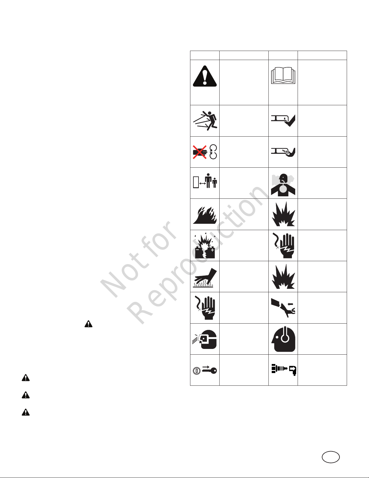
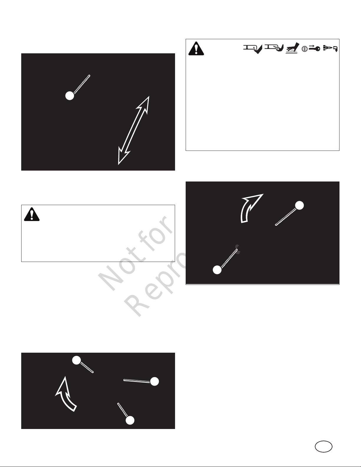
Hazard Symbols
General Operator Safety Warning
Symbol Meaning Symbol Meaning
Safety
information
about hazards
that can result in
personal injury.
Thrown objects
hazard.
Amputation
hazard - do not
touch moving
parts.
Keep
bystanders and
children away.
Read and
understand
the operator’s
manual before
operating or servicing the unit.
Amputation
hazard - rotating
blade. Keep feet
away.
Amputation
hazard - rotating blade. Keep
hands away.
Toxic fume hazard.
Manual Contents:
Operator Safety ............................................................... 3
Features and Controls .................................................... 9
Safety Interlock Systems Checks ................................ 10
Operation ....................................................................... 10
Maintenance .................................................................. 19
Troubleshooting ............................................................ 24
Specifications ................................................................ 25
The images in this document are representative, and are
meant to complement the instructional text they accompany.
Your unit may vary from the images displayed. LEFT and
RIGHT are as seen from the operator’s position.
Operator Safety
Safety Alert Symbol and Signal Words
The safety alert symbol indicates a potential personal
injury hazard. A signal word (DANGER, WARNING, or
CAUTION) is used with the alert symbol to designate a
degree or level of hazard seriousness. A safety symbol may
be used to represent the type of hazard. The signal word
NOTICE is used to address practices not related to
personal injury.
DANGER indicates a hazard which, if not avoided, will
result in death or serious injury.
Fire hazard. Explosion haz-
ard.
Battery
explosion
hazard.
Hot surface
hazard.
Shock hazard. Kickback haz-
Eye protection
recommended.
Remove the
key before
performing
service.
Shock hazard.
Explosion hazard.
ard.
Ear protection
recommended
for extended
use.
Remove the
spark plug wire
before performing service.
WARNING indicates a hazard which, if not avoided,
could result in death or serious injury.
CAUTION indicates a hazard which, if not avoided,
could result in minor or moderate injury.
NOTICE indicates an action that could result in damage to
the product.
3
Not for
Reproduction
WARNING
This powerful cutting machine is capable of amputating
hands and feet and can throw objects that can cause
injury and damage! Failure to comply with the following
SAFETY instructions could result in serious injury or
death to the operator or other persons. The owner of the
machine must understand these instructions and must
allow only persons who understand these instructions to
operate machine. Each person operating the machine
must be of sound mind and body and must not be under
the influence of any substance, which might impair vision,
dexterity or judgment.
3. DO NOT allow children or others to ride on machine,
attachments or towed equipment (even with the blades
OFF). They may fall and be seriously injured.
4. DO NOT allow pre-teenage children to operate machine.
5. ALLOW only responsible adults & teenagers with
mature judgment under close adult supervision to
operate machine.
6. DO NOT operate blades in reverse unless absolutely
necessary. STOP BLADES. LOOK and SEE behind and
down for children, pets and hazards before and while
backing.
7. USE EXTRA CARE when approaching blind corners,
shrubs, trees, or other objects that may obscure vision.
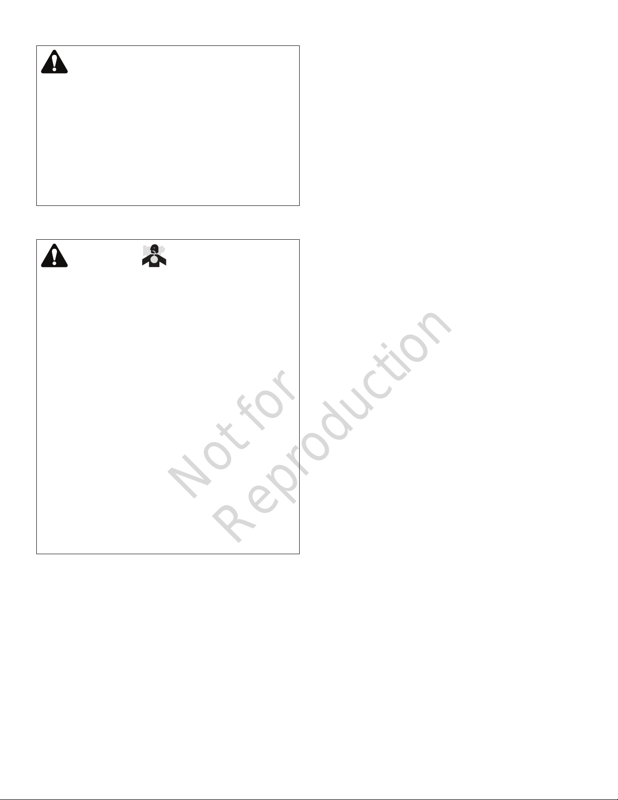
Carbon Monoxide Warning
WARNING
POISONOUS GAS HAZARD. Engine exhaust contains
carbon monoxide, a poisonous gas that could kill
you in minutes. You CANNOT see it, smell it, or taste
it. Even if you do not smell exhaust fumes, you could
still be exposed to carbon monoxide gas. If you start
to feel sick, dizzy, or weak while using this product,
shut it off and get to fresh air RIGHT AWAY. See a
doctor. You may have carbon monoxide poisoning.
• Operate this product ONLY outside far away from
windows, doors and vents to reduce the risk of carbon
monoxide gas from accumulating and potentially being
drawn towards occupied spaces.
• Install battery-operated carbon monoxide alarms or
plug-in carbon monoxide alarms with battery back-up
according to the manufacturer’s instructions. Smoke
alarms cannot detect carbon monoxide gas.
• DO NOT run this product inside homes, garages,
basements, crawlspaces, sheds, or other partiallyenclosed spaces even if using fans or opening doors
and windows for ventilation. Carbon monoxide can
quickly build up in these spaces and can linger for
hours, even after this product has shut off.
• ALWAYS place this product downwind and point the
engine exhaust away from occupied spaces.
Protection for Children
Tragic accidents can occur if the operator is not alert to the
presence of children. Children are often attracted to the
machine and the mowing activity. Children who have been
given rides in the past may suddenly appear in the mowing
area for another ride and be run over or backed over by the
machine. Never assume that children will remain where you
last saw them.
1. KEEP children out of the mowing area and under the
watchful care of a responsible adult other than the
operator.
2. DO NOT allow children in yard when machine is
operated (even with the blade OFF).
Protection Against Tip-Overs/Roll-Overs
Slopes are a major factor related to loss-of-control and
tipover/roll-over accidents, which can result in severe injury
or death. All slopes require extra CAUTION. If you cannot
back up the slope or if you feel uneasy on the slope, DO
NOT mow it. Use extra care with grass catchers or other
attachments; these affect the handling and the stability of
the machine.
1. DO NOT operate machine on slopes exceeding 10
degrees (18% grade).
2. Turn blades OFF when traveling uphill. Use a slow
speed and avoid sudden or sharp turns.
3. DO NOT operate machine back and forth across face of
slopes. Operate up and down. Practice on slopes with
blades off.
4. AVOID starting, stopping or turning on slopes. If
machine stops going uphill or tires lose traction, turn
blades OFF and back slowly straight down the slope.
5. STAY ALERT for holes and other hidden hazards. Tall
grass can hide obstacles. Keep away from ditches,
washouts, culverts, fences and protruding objects.
6. KEEP A SAFE DISTANCE (at least two mower widths)
away from edge of ditches and other drop offs. The
machine could turn over if an edge caves in.
7. Always begin forward motion slowly and with caution.
8. DO NOT begin forward motion while the machine is
rolling backwards. A rearward tip-over may result.
9. Use weights or a weighted load carrier in accordance
with instructions supplied with a grass catcher or other
attachments. DO NOT operate machine on slopes
exceeding 10 degrees (18% grade) when equipped with
grass catcher or other attachments.
10. DO NOT put your foot on the ground to try to stabilize
the machine.
11. DO NOT operate machine on wet grass. Reduced
traction could cause sliding.
4

Not for
Reproduction
en
12. Choose a low enough speed setting so that you will not
have to stop or shift on a slope. Tires may lose traction
on slopes even though the brakes are functioning
properly.
13. DO NOT operate machine under any condition where
traction, steering or stability is doubtful.
14. Always keep the machine in gear when going down
slopes. DO NOT shift to neutral (or actuate hydro roll
release) and coast downhill.
15. Machine stability is tested in accordance with the
applicable ANSI B71 standard using an operator weight
of 200 lbs. To minimize the risk of a tip-over or roll-over,
operators weighing more than 200 lbs. should further
limit the ground speed and the degree of slope to be
mowed.
Preparation
1. Read, understand, and follow instructions and warnings
in this manual and on the machine, engine and
attachments. Know the controls and the proper use of
the machine before starting.
2. Only mature, responsible persons shall operate the
machine and only after proper instruction.
3. Data indicates that operators age 60 and above, are
involved in a large percentage of mower-related injuries.
These operators should evaluate their ability to operate
the mower safely enough to protect themselves and
others from serious injury.
4. Handle fuel with extra care. Fuels are flammable
and vapors are explosive. Use only an approved fuel
container. DO NOT remove fuel cap or add fuel with
engine running. Add fuel outdoors only with engine
stopped and cool. Clean spilled fuel from machine. DO
NOT smoke.
5. Practice operation of machine with BLADES OFF to
learn controls and develop skills.
6. Check the area to be mowed and remove all objects
such as toys, wire, rocks, limbs and other objects that
could cause injury if thrown by blade or interfere with
mowing.
7. Keep people and pets out of mowing area. Immediately
STOP blades, STOP engine, and STOP machine if
anyone enters the area.
8. Check shields, deflectors, switches, blade controls and
other safety devices frequently for proper operation and
location.
9. Make sure all safety decals are clearly legible. Replace
if damaged.
10. Protect yourself when mowing and wear safety glasses,
a dust mask, hearing protection, long pants and
substantial footwear.
11. Know how to STOP blades and engine quickly in
preparation for emergencies.
12. Use extra care when loading or unloading the machine
into a trailer or truck.
13. Check grass catcher components frequently for signs of
wear or deterioration and replace as needed to prevent
injury from thrown objects going through weak or worn
spots.
Safe Handling of Gasoline
To avoid personal injury or property damage, use extreme
care in handling gasoline. Gasoline is extremely flammable
and the vapors are explosive.
1. Extinguish all cigarettes, cigars, pipes and other
sources of ignition.
2. Use only an approved fuel container.
3. DO NOT remove fuel cap or add fuel with the engine
running. Allow the engine to cool before refueling.
4. DO NOT refuel the machine indoors.
5. DO NOT store the machine or fuel container inside
where there is an open flame, spark or pilot light such as
on a water heater or other appliances.
6. DO NOT fill fuel containers inside a vehicle or on a
truck or trailer bed with a plastic liner. Always place the
containers on the ground away from the vehicle before
filling.
7. Remove gas-powered equipment from the vehicle or
trailer and refuel it on the ground. If this is not possible,
then refuel equipment using a portable container, rather
than a gasoline dispenser nozzle.
8. DO NOT start gas powered equipment in enclosed
vehicles or trailers.
9. Keep the nozzle in contact with the rim of the fuel
tank or container opening at all times until fueling is
complete. DO NOT use a nozzle lock-open device.
10. If fuel is spilled on clothing, change clothing
immediately.
11. Never overfill a fuel tank. Replace fuel cap and tighten
securely.
Operation
1. Mount and dismount machine from left side. Keep clear
of discharge opening at all times.
2. Start engine from operator’s seat, if possible. Make sure
blades are OFF and parking brake is set.
3. DO NOT leave machine with engine running. STOP
engine, STOP blades, SET brake, and remove key
before leaving operators position of any reason.
4. DO NOT operate machine unless properly seated with
feet on feet rests or pedal(s).
5

Not for
Reproduction
5. STOP BLADES and ENGINE and make sure blades
have stopped before removing grass catcher or
unclogging mower to prevent loss of fingers or hand.
6. Blades must be OFF except when cutting grass. Set
blades in highest position when mowing over rough
ground.
7. Keep hands and feet away from rotating blades
underneath deck. DO NOT place foot on ground while
BLADES are ON or machine is in motion.
8. DO NOT operate machine without entire grass
catcher or guards in place and working. DO NOT point
discharge at people, passing cars, windows or doors.
9. Slow down before turning.
10. Watch out for traffic when near or crossing roadways.
11. STOP engine immediately after striking an obstruction.
Inspect machine and repair damage before resuming
operation.
12. Operate machine only in daylight or with good artificial
light.
13. Exercise CAUTION when pulling loads. Limit loads to
those you can safely control and attach loads to hitch
plate as specified with attachment instructions.
14. On slopes, the weight of the towed equipment may
cause loss of traction and loss of control. When towing,
travel slowly and allow extra distance to stop.
15. DO NOT operate engine in enclosed areas. Engine
exhaust gases contain carbon monoxide, a deadly
poison.
16. DO NOT discharge material against a wall or
obstruction. Material may ricochet back towards the
operator.
17. Only use accessories approved by the manufacturer.
See manufacturer’s instructions for proper operation
and installation of accessories.
18. Duration of machine operation may need to be limited
due to exposure to noise and vibration.
19. DO NOT operate machine when the risk of lightning is
present.
Towing
1. Tow only with a machine that has a hitch designed for
towing. DO NOT attach towed equipment except at the
hitch point.
2. Refer to “Towing Implements” in the Operation section
regarding weight limits for towed equipment and towing
on slopes.
3. DO NOT allow children or others on towed equipment.
4. On slopes, the weight of the towed equipment may
cause loss of traction and loss of control. Use caution
while operating on slopes.
5. Travel slowly and allow extra distance to stop.
Maintenance
1. DO NOT store machine or fuel container inside where
fumes may reach an open flame, spark or pilot light
such as in a water heater, furnace, clothes dryer or
other gas appliance. Allow engine to cool before storing
machine in an enclosure. Store fuel container out of
the reach of children in a well ventilated, unoccupied
building.
2. Keep engine and machine free of grass, leaves or
excess grease to reduce fire hazard and engine
overheating.
3. When draining fuel tank, drain fuel into an approved
container outdoors and away from open flame.
4. Check brakes frequently; adjust, repair or replace as
needed.
5. Keep all bolts, nuts and screws properly tight. Check
that all cotter pins are in proper position.
6. Always provide adequate ventilation when running
engine. Exhaust gases contain carbon monoxide, an
odorless and deadly poison.
7. Disconnect negative (black) cable from battery before
performing maintenance or service. Cranking engine
could cause injury.
8. DO NOT work under machine without safety blocks.
9. DO NOT stand unit on end.
10. Service engine and make adjustments only when
engine is stopped. Remove spark plug wire(s) from
spark plug(s) and secure wire(s) away from spark
plug(s).
11. DO NOT change engine governor speed settings or
overspeed engine.
12. Lubricate machine at intervals specified in manual to
prevent controls from binding.
13. Mower blades are sharp and can cut. Wrap the blades
or wear heavy leather gloves and use CAUTION when
handling them.
14. DO NOT test for spark by grounding spark plug next
to spark plug hole; spark plug could ignite gas exiting
engine.
15. Have machine serviced by an authorized dealer at least
once a year and have the dealer install any new safety
devices.
16. Maintain or replace safety and instruction labels as
necessary.
17. Use only factory authorized replacement parts or
equivalent when making repairs.
6
Not for
Reproduction
en
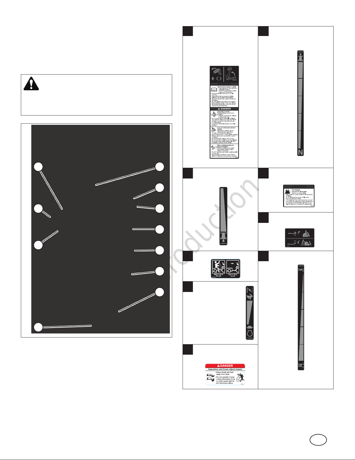
Safety and Instructional Decals - Domestic
Before operating your unit, read and understand the safety
and instructional decals (compare Figure 1 with the table).
The cautions, warnings, and instructions are for your safety.
To avoid personal injury or damage to the unit, understand
and follow all the decals.
WARNING
If any safety or instructional decals become worn or
damaged, and cannot be read, order replacement decals
from your dealer.
Clutch/Brake Operation
A
Blade Engage
Operation
General Warnings
Forward Speed
B
(Manual Drive Models)
I
H
G
F
A
Reverse Speed
C
(Manual Drive Models)
H
J
B
C
D
E
Weight Limitation
F
Engine Speed
G
Control
Choke Control
(Select Models)
Use Caution When
D
Refueling
Transmission Release
E
(Hydro Drive Models)
Cutting Height
I
Figure 1
Discharge Safety (2 - 1
H
on each side of deck)
7
Not for
Reproduction
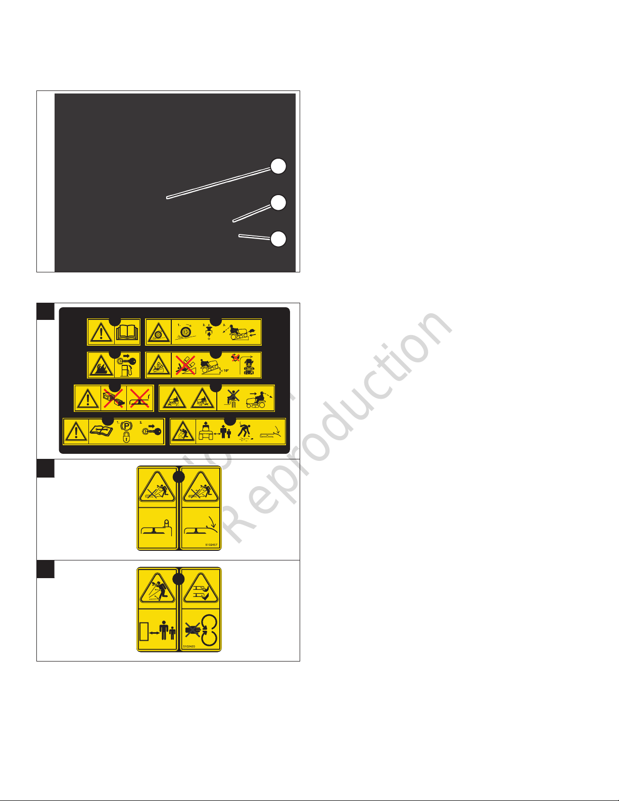
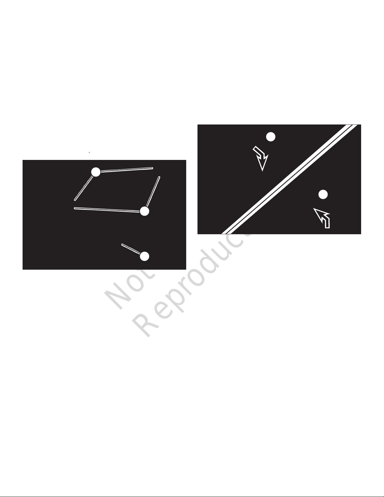
Safety and Instructional Decals - ANSI Export
Before operating your unit, read and understand the safety
and instructional decals (compare Figure 2 with the table)
1. WARNING: Read and understand the Operator’s
Manual before using this machine. Know the location
and function of all controls. Do not operate this machine
unless you are trained.
2. DANGER - LOSS OF TRACTION, SLIDING,
STEERING AND CONTROL ON SLOPES HARZARD:
If machine stops forward motion or starts sliding on a
slope, stop the blades and drive slowly off the slope.
Figure 2
A
A
B
C
1
3
5
7
2
5
6
8
3. DANGER: FIRE HAZARD: Keep unit free of grass,
leaves and excess oil. Do not add fuel while engine is
hot or running. Stop engine, remove key and allow to
cool for at least 3 minutes prior to adding fuel. Do not
add fuel indoors, in an enclosed trailer, garage or other
enclosed areas. Clean up spilled fuel. Do not smoke
while operating this machine.
4. DANGER - TIPPING AND SLIPPING HAZARD: Mow
up and down slopes not across. Do not operate on
slopes over 10 degrees. Avoid sudden and sharp (fast)
turns while on slopes.
5. DANGER - AMPUTATION AND DISMEMBERMENT
HAZARD: To avoid injury from rotating blades and
moving parts, keep safety devices (guards, shields and
switches) in place and working.
6. Do not mow when children or others are around. Never
carry riders especially children even with the blades off.
Do not mow in reverse unless absolutely necessary.
Look down and behind – before and while backing.
7. Consult technical literature before performing technical
repairs or maintenance. When leaving the machine,
shutoff engine, set the parking brake to the lock position
and remove the ignition key.
B
C
9
10
8. Keep by-standers and children a safe distance away.
Remove objects that can be thrown by the blade. Do not
mow without discharge chute in place.
9. Do not mow without discharge chute or entire grass
catcher in place.
10. To avoid injury from rotating blades, stay clear of deck
edge and keep others away.
8
Not for
Reproduction
en
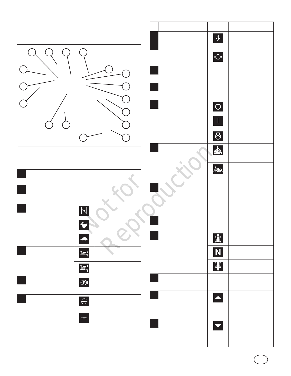
Features and Controls
Compare the features and controls in Figure 3 with the table
below.
O
AN
B
Ref.
G
Description Icon(s) Icon Definition
Clutch/Brake Pedal
- engages clutch
(manual drive
models) and brake
Clutch engaged
(manual drive
models)
Brake on (engaged)
M
L
K
J I
Figure 3
Ref.
A Operator Seat
B Steering Wheel -
C
Description Icon(s) Icon Definition
controls direction of
unit
Engine Speed
Control (hidden
from view) - controls
engine speed
C
Q
-- --
-- --
Choke on (closed) if equipped
Engine speed fast
Headlight (not shown;
D
E
F
G
H
P
H
select models)
Mulching Cover
I
Ignition Switch -
J
starts engine
Transmission
K
Release Lever
(hidden from view;
hydro drive models) releases transmission
so unit can roll freely
Reverse Mowing
L
Switch - temporarily
allows mower blade
to operate with
transmission in
reverse
Recoil Start Handle
M
(hidden from view)
-- --
-- --
Engine off
Engine on (run)
Engine start
Transmission
engaged (locked)
Transmission
released (unlocked)
-- --
-- --
Cutting Height Adjust
D
Lever - adjusts
cutting height
E Parking Brake Latch
(hidden from view) locks brake
F Blade Control -
engages mower
blade
Engine speed low
Cutting height low
Cutting height high
Parking brake on
(engaged)
Blade on (engaged)
Blade off
(disengaged
Transmission Shift
N
Lever (manual drive
models) - selects
transmission speed
and direction
Fuel Tank
O
Forward Ground
P
Speed Pedal (hydro
drive models) controls forward
ground speed
Reverse Ground
Q
Speed Pedal (hydro
drive models) controls reverse
ground speed
Forward ground
speed
Neutral (no ground
speed)
Reverse ground
speed
-- --
Forward ground
speed
Reverse ground
speed
9
Not for
Reproduction
Safety Interlock Systems Checks
Synthetic 5W-30
Operation
WARNING
DO NOT operate machine if any safety interlock or safety
device is not in place and functioning properly. Contact
your dealer immediately for assistance. DO NOT attempt
to defeat, modify or remove any safety device.
Engine must not start if:
1. The Clutch/Brake Pedal is not fully depressed OR,
2. The Blade Control is in the ON (engaged) position.
Engine should start if:
1. The Blade Control is in the OFF (disengaged) position
AND,
2. The Clutch/Brake Pedal is fully depressed.
Engine and blade must stop if:
1. The operator rises off of the operator seat while the
Blade Control is in the ON (engaged) position OR,
2. The operator rises off of the operator seat while the
Clutch/Brake Pedal is not fully depressed OR,
3. The operator attempts to drive the unit in reverse with
the mower blade engaged and the reverse mowing
option function (RMO) not activated.
WARNING
Once mower blade is disengaged, it should come
to a complete stop in 5 seconds or less. If the blade
continues to rotate after 5 seconds, DO NOT operate the
machine. Return the machine to an authorized dealer for
adjustment.
Before Starting
Make the following checks and perform the service required
before each start-up:
1. Check the tire pressure; add or release air as
needed. Refer to “How To Check Tire Pressure” in the
Maintenance section.
2. Check guards, deflectors and covers to make sure all
are in place and securely tightened.
3. Check engine oil and add oil as needed. Refer to “How
To Check/Add Oil”.
4. Add fuel to the fuel tank as needed. Refer to “How to
Add Fuel”.
5. Adjust the operator seat as needed to the most
comfortable position. Refer to “How To Adjust The
Operator Seat”.
6. Check all operator controls to ensure they operate freely
without binding.
7. Perform the Safety Interlock System Checks. Refer to
“Safety Interlock System Checks”.
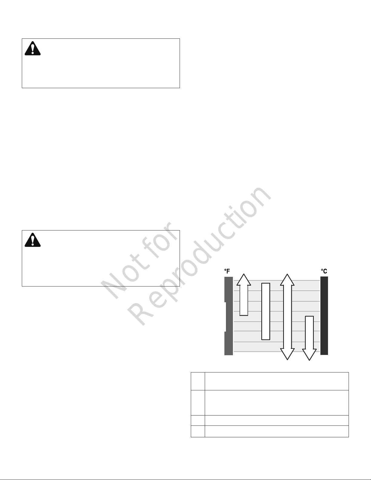
Oil Recommendations
We recommend the use of Briggs & Stratton Warranty
Certified oils for best performance. Other high-quality
detergent oils are acceptable if classified for service SF,
SG, SH, SJ or higher. Do not use special additives.
Outdoor temperatures determine the proper oil viscosity for
the engine. Use the chart to select the best viscosity for the
outdoor temperature range expected.
10
A
SAE 30 *
†
B
10W-30
C
D
5W-30
A SAE 30 - Below 40°F (4°C) the use of SAE 30 will
result in hard starting.
B 10W-30 - Above 80°F (27°C) the use of 10W-30 may
cause increased oil consumption. Check oil level
more frequently.
C Synthetic 5W-30
D 5W-30
Not for
Reproduction
en
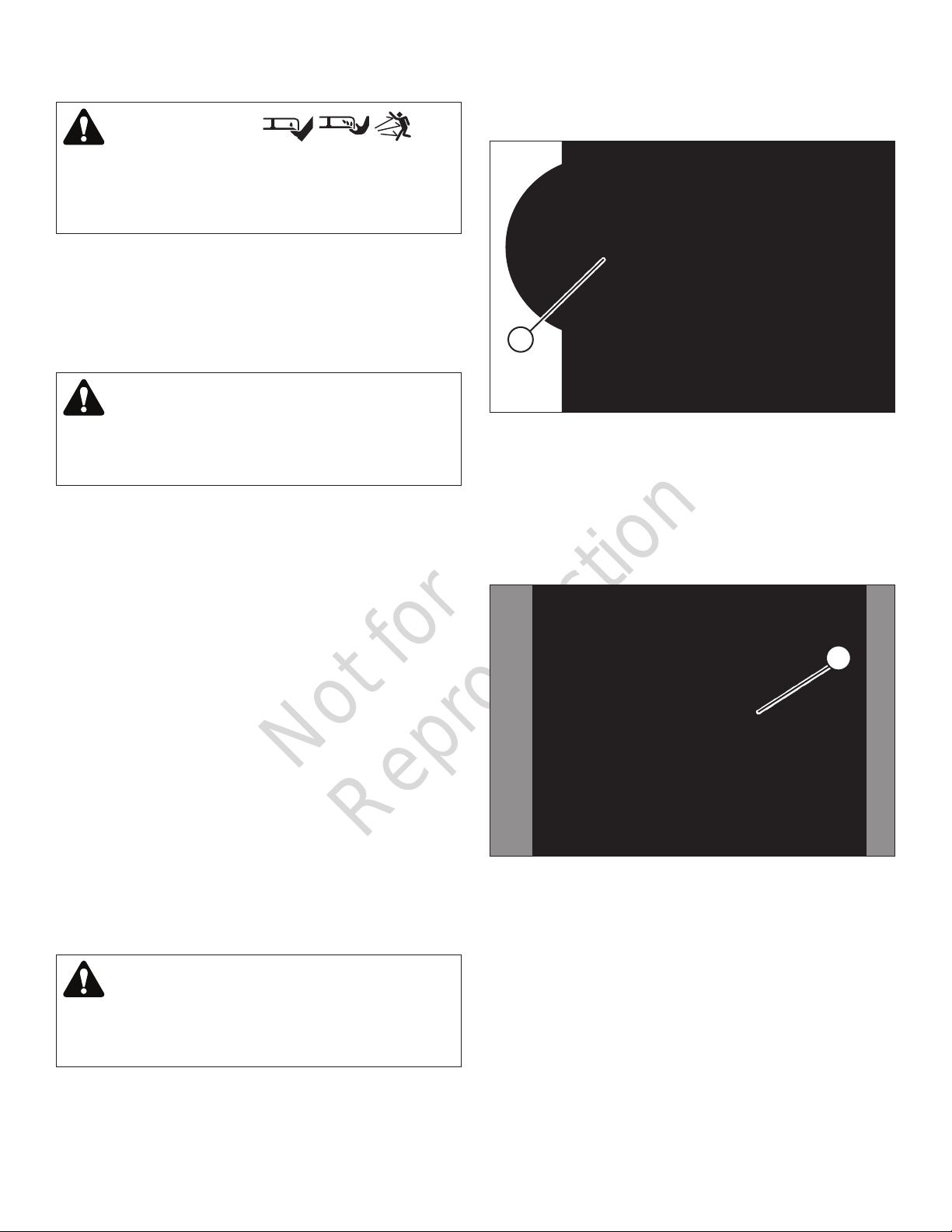
How To Check/Add Oil
Before adding or checking the oil
• Place engine level.
• Clean the oil fill area of any debris.
1. Remove the dipstick (A, Figure 4) and wipe with a clean
cloth.
NOTE:
opening behind the operator seat.
2. Insert and tighten the dipstick.
3. Remove the dipstick and check the oil level. It should be
at the top of the full indicator (B) on the dipstick.
4. If low, add oil slowly into the engine oil fill (C). Do not
overfill. After adding oil, wait one minute and then
recheck the oil level.
5. Replace and tighten the dipstick.
On some models, the dipstick is accessible through an
Fuel Recommendations
Fuel must meet these requirements:
• Clean, fresh, unleaded gasoline.
• A minimum of 87 octane/87 AKI (91 RON). High altitude
use, see below.
• Gasoline with up to 10% ethanol (gasohol) is
acceptable.
NOTICE: Do not use unapproved gasolines, such as E15
and E85. Do not mix oil in gasoline or modify the engine to
run on alternate fuels. Use of unapproved fuels will damage
the engine components, which will not be covered under
warranty.
To protect the fuel system from gum formation, mix a fuel
stabilizer into the fuel. See Storage. All fuel is not the
same. If starting or performance problems occur, change
fuel providers or change brands. This engine is certified to
operate on gasoline.
Figure 4
A
The emissions control system for this engine is EM (Engine
Modifications).
High Altitude
At altitudes over 5,000 feet (1524 meters), a minimum 85
octane/85 AKI (89 RON) gasoline is acceptable.
For carbureted engines, high altitude adjustment is
required to maintain performance. Operation without this
C
B
A
adjustment will cause decreased performance, increased
fuel consumption, and increased emissions. Contact a
Briggs & Stratton Authorized Service Dealer for high altitude
adjustment information. Operation of the engine at altitudes
below 2,500 feet (762 meters) with the high altitude
adjustment is not recommended.
For Electronic Fuel Injection (EFI) engines, no high altitude
adjustment is necessary.
11
Not for
Reproduction
How To Add Fuel
WARNING
Fuel and its vapors are extremely flammable and
explosive. Fire or explosion can cause severe burns or
death.
When Adding Fuel
• Turn engine off and let engine cool at least 5 minutes
before removing the fuel cap.
• Fill fuel tank outdoors or in well-ventilated area.
• Do not overfill fuel tank. To allow for expansion of the
fuel, do not fill above the bottom of the fuel tank neck.
• Keep fuel away from sparks, open flames, pilot lights,
heat, and other ignition sources.
• Check fuel lines, tank, cap, and fittings frequently for
cracks or leaks. Replace if necessary.
• If fuel spills, wait until it evaporates before starting
engine.
1. Clean the fuel cap area of dirt and debris. Remove the
fuel cap (A, Figure 5).
2. Fill the fuel tank with fuel. To allow for expansion of the
fuel, do not fill above the bottom of the fuel tank neck
(B).
3. Reinstall the fuel cap.
How To Adjust The Operator Seat
With the engine stopped:
1. Raise the operator seat.
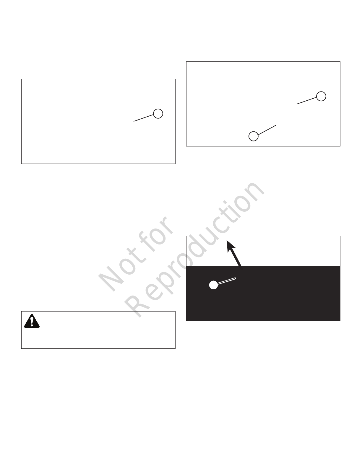
2. Loosen the two adjusting knobs (A, Figure 6) and
move the seat to the desired position. After adjustment,
tighten the knobs securely.
3. Lower the operator seat.
A
Figure 6
Figure 5
A
B
12
Not for
Reproduction
en
How To Start The Engine
WARNING
POISONOUS GAS HAZARD. Engine exhaust contains
carbon monoxide, a poisonous gas that could kill
you in minutes. You CANNOT see it, smell it, or taste
it. Even if you do not smell exhaust fumes, you could
still be exposed to carbon monoxide gas. If you start
to feel sick, dizzy, or weak while using this product,
shut it off and get to fresh air RIGHT AWAY. See a
doctor. You may have carbon monoxide poisoning.
• Operate this product ONLY outside far away from
windows, doors and vents to reduce the risk of carbon
monoxide gas from accumulating and potentially
being drawn towards occupied spaces.
• Install battery-operated carbon monoxide alarms or
plug-in carbon monoxide alarms with battery back-up
according to the manufacturer’s instructions. Smoke
alarms cannot detect carbon monoxide gas.
• DO NOT run this product inside homes, garages,
basements, crawlspaces, sheds, or other partiallyenclosed spaces even if using fans or opening doors
and windows for ventilation. Carbon monoxide can
quickly build up in these spaces and can linger for
hours, even after this product has shut off.
• ALWAYS place this product downwind and point the
engine exhaust away from occupied spaces.
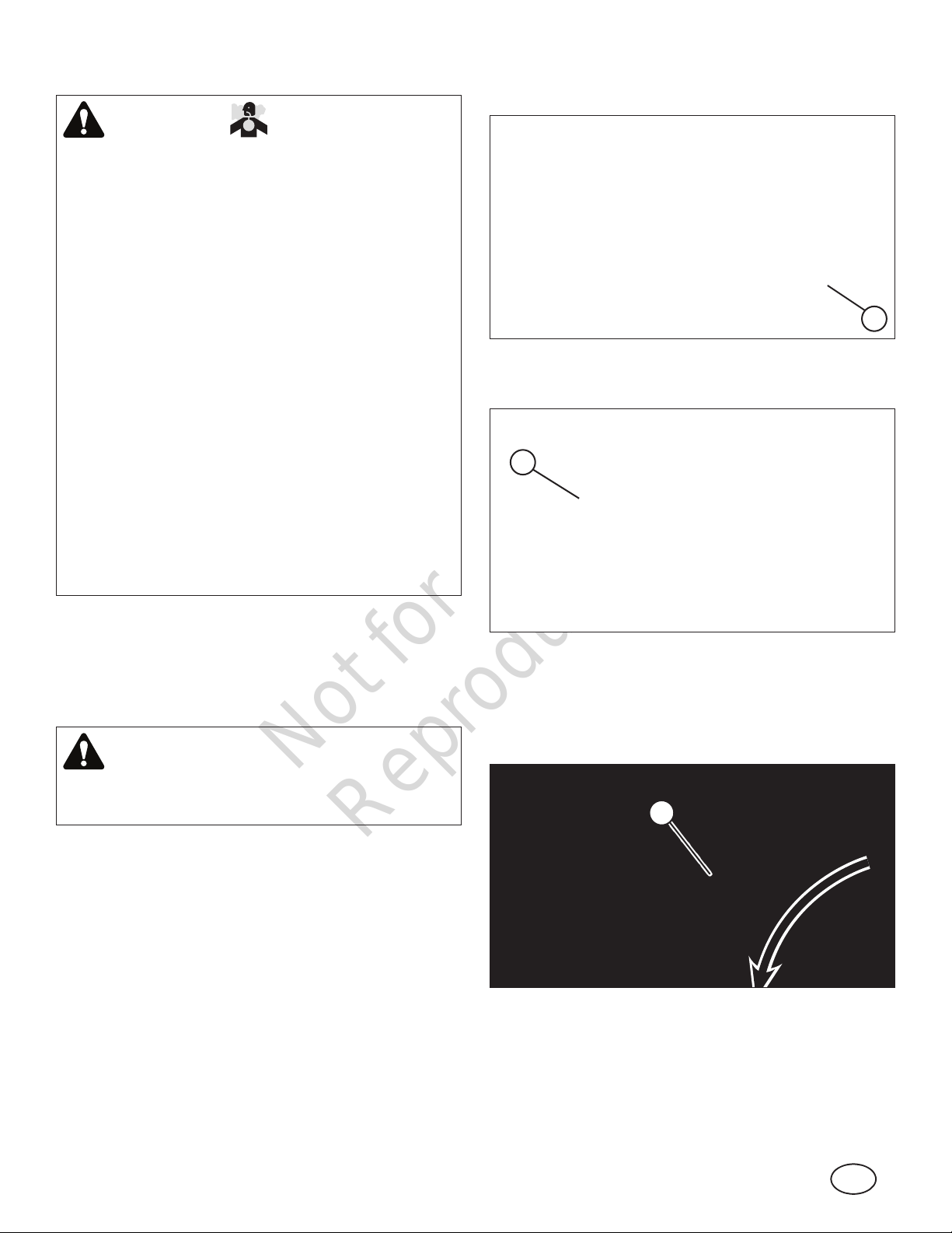
3. Make sure the Blade Control (A, Figure 7) is in the OFF
position.
A
Figure 7
4. Fully depress the Clutch/Brake Pedal (A, Figure 8).
A
Electric Start:
1. Sit squarely in the operator seat.
2. Manual Drive Models - Move the transmission shift lever
to the Neutral (‘N’) position. Refer to “How To Engage
The Transmission”.
WARNING
DO NOT start the engine with the transmission shift lever
in a drive position. Follow starting instructions carefully.
Figure 8
5. Move the engine speed control (A, Figure 9) to the
FAST position (or CHOKE position, if equipped).
NOTE: The CHOKE position is not required when starting
a warm engine.
A
Figure 9
13
Not for
Reproduction
6. Insert the ignition key (A, Figure 10) into the ignition
switch. Turn the key to the START position until the
engine starts.
NOTE: When the ignition key is turned to START, the
engine will turn over, but will not start unless the Clutch/
Brake pedal is fully depressed and the Blade Control is in
the OFF position.
A
NOTE: The CHOKE position is not required when starting
a warm engine.
5. Insert the ignition key (A, Figure 11) into the ignition
switch. Turn the key to the RUN position (B).
A
B
Figure 11
Figure 10
NOTE: If after 5 seconds of cranking the engine does not
start, release the key, make sure the Clutch/Brake Pedal is
fully depressed, and attempt starting again after waiting for
approximately 20 seconds.
7. After the engine starts, move the engine speed control to
the FAST position (if equipped with choke) and allow a
brief warm-up until engine runs smooth.
NOTE: Always operate with the engine speed control in the
FAST position.
NOTE: The headlight (featured on select models) is operational any time the ignition switch is in the RUN or START
position.
Recoil Start:
1. Manual Drive Models - Move the transmission shift lever
to the Neutral (‘N’) position. Refer to “How To Engage
The Transmission”.
WARNING
DO NOT start the engine with the transmission shift lever
in a drive position. Follow starting instructions carefully.
6. Grasp the recoil start handle on the engine (A, Figure
12) and pull briskly until the engine starts.
7. After the engine starts, move the engine speed control
to the FAST position (if equipped with choke) and allow
a brief warm-up period until engine runs smooth.
NOTE: Always operate with the engine speed control in the
FAST position.
NOTE: The headlight (featured on select models) is operational any time the ignition switch is in the RUN position.
A
Figure 12
2. Make sure the Blade Control (A, Figure 7) is in the OFF
position.
3. Set the parking brake. Refer to “How To Set The Parking
Brake”.
4. Move the engine speed control (A, Figure 9) to the
FAST position (or CHOKE position, if equipped).
14
Not for
Reproduction
en
How To Engage The Mower Blade
1. Start the engine.
2. Move the blade control (A, Figure 13) to the ON position.
A
Figure 13
How To Engage The Transmission
Manual Drive Models:
1. Start the engine.
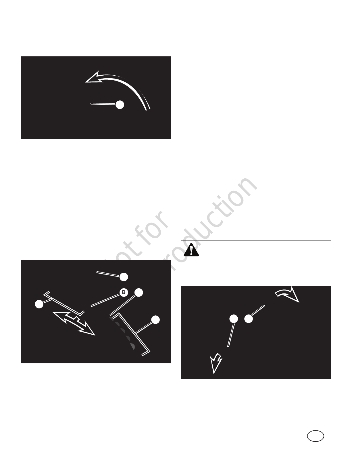
2. To move forward:
• Depress the clutch/brake pedal (A, Figure 8).
• Move the transmission shift lever (A, Figure 14) from
the Neutral (‘N’) position (B) into the first forward speed
notch (C).
• Release the clutch/brake pedal to begin forward motion.
• During forward motion, the transmission shift lever may
be placed in any desired forward speed (D) without
depressing the clutch/brake pedal.
3. To move backward:
• Depress the clutch/brake pedal (A, Figure 8).
• Move the transmission shift lever (A, Figure 14) from the
Neutral (‘N’) position (B) into the reverse speed slot (E).
• During reverse motion, the transmission shift lever
may be placed in any desired reverse speed without
depressing the clutch/brake pedal.
Hydro Drive Models:
1. Start the engine.
2. Make sure the parking brake is released. Refer to “How
To Set The Parking Brake”.
3. To move forward:
• Slowly depress the forward ground speed pedal (A,
Figure 15) to begin forward motion. Increase ground
speed by further depressing the pedal.
4. To move backward:
• Slowly depress the reverse ground speed pedal (B) to
begin reverse motion. Increase ground speed by further
depressing the pedal.
NOTE: For best cutting results, choose a slow forward
speed with the engine speed control in the FAST position.
This combination will allow the mower blade to lift the grass
while cutting smoothly and evenly.
NOTICE: If the transmission is moved into reverse while the
mower blade is engaged, the engine will shut off. If mowing
in reverse is necessary, refer to “Reverse Mowing Option
(RMO)”.
WARNING
E
Figure 14
A
B C
LOOK and SEE behind and down for children, pets and
hazards before and while backing.
D
Figure 15
B A
15
Not for
Reproduction
WARNING
DO NOT leave the machine with the engine running.
STOP Blade. STOP engine. Shift to neutral and engage
parking brake. Remove key.
Mower Blade
1. Stop the mower blade by moving the blade control (A,
Figure 7) to the OFF position.
WARNING
How To Stop The Engine, Transmission And
Mower Blade
Engine
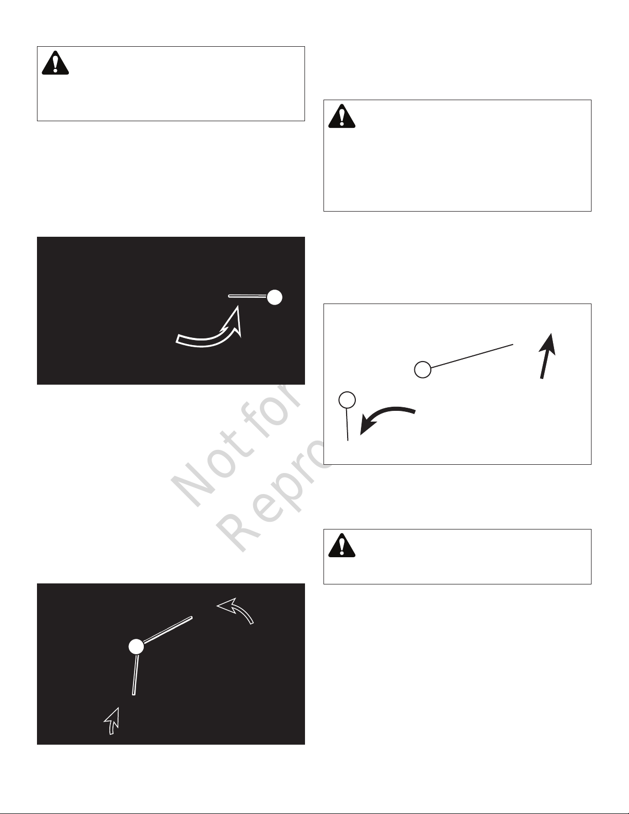
1. Stop the engine by turning the ignition key (A, Figure 16)
to the OFF position.
2. Remove the key.
A
Figure 16
Transmission
• Manual Drive Models:
Once blade is disengaged, it should come to a complete
stop in 5 seconds or less. If the blade continues to rotate
after 5 seconds, the blade brake must be adjusted.
Return machine to an authorized dealer for adjustment.
DO NOT CONTINUE to operate machine until blade
brake is adjusted and functioning properly.
How To Set The Parking Brake
1. Fully depress the clutch/brake pedal (A, Figure 18).
2. Slide the parking brake latch (B) up and hold while
releasing the clutch/brake pedal. The parking brake is now
set.
B
A
1. Stop motion of the unit by fully depressing the clutch/
brake pedal (A, Figure 8) to disengage the clutch and
apply the brake.
2. Return the transmission shift lever to the Neutral (‘N’)
position. Refer to “How To Engage The Transmission”.
• Hydro Drive Models:
1. Stop motion of the unit by fully releasing the ground
speed pedals (A, Figure 17). Additional braking can be
achieved by depressing the brake pedal (A, Figure 8).
A
Figure 18
3. To release the parking brake, fully depress the clutch/
brake pedal. The parking brake will release automatically.
WARNING
DO NOT park the machine on slopes.
Figure 17
16
Not for
Reproduction
en
How To Adjust The Cutting Height
1. Raise or lower the cutting height adjust lever (A, Figure
19) into the desired height of cut notch.
A
Figure 19
Reverse Mowing Option (RMO)
How To Install The Discharge Deflector
WARNING
DO NOT attempt any adjustments, maintenance, service
or repairs with the engine running.
• STOP engine.
• STOP blade.
• Engage parking brake.
• Remove key.
• Remove spark plug wire from spark plug and secure
away from plug.
• Engine and components are HOT. Avoid serious
burns, allow all parts to cool before working on
machine.
1. Remove the nut and washer (A, Figure 21) securing the
bottom edge of the mulching cover (B) to the mower
deck.
WARNING
Mowing in reverse can be hazardous to bystanders.
Tragic accidents can occur if the operator is not alert to
the presence of children. Never activate RMO if children
are present. Children are often attracted to the unit and
the mowing activity.
1. Engage the mower blade. Refer to “How To Engage The
Mower Blade”.
2. Insert the supplied key (A, Figure 20) into the RMO
switch (B), and turn the key to activate the RMO
function. The LED light (C) indicates that the RMO
function is now activated.
3. Engage the transmission in reverse. Refer to “How To
Engage The Transmission”.
4. The RMO function is deactivated when the mower blade
is disengaged.
A
B
A
Figure 21
Figure 20
C
B
17
Not for
Reproduction
2. Raise the mulching cover. Replace the washer and nut
onto the retaining bolt in the deck, tightening securely.
3. Install the discharge deflector (A, Figure 22) to the
mower deck, making sure that the slots (B) in the
deflector fit over the locking tabs (C) on the mulching
cover hinge bracket.
4. Lower the mulching cover.
5. To remove the discharge deflector:
• Raise the mulching cover.
• Lift and remove the discharge deflector from the mower
deck.
• Remove the nut and washer from the retaining bolt in
the deck.
• Lower the mulching cover, securing with the washer and
nut. Tighten securely.
C
B
Hydro Drive Models:
1. Make sure the unit is parked on a flat, even surface.
2. Release the parking brake, if set. Refer to “How To Set
The Parking Brake”.
3. Move the transmission release lever (located behind
the right rear tire) out and down into the locking slot (A,
Figure 23) to disengage the transmission.
4. The unit can now be pushed by hand.
5. After moving the unit to the desired location, move the
transmission release lever up and in (B) to engage the
transmission.
A
B
A
Figure 22
How To Push The Unit By Hand
Manual Drive Models:
1. Make sure the unit is parked on a flat, even surface.
2. Make sure the transmission shift lever is in the
Neutral (N) position. Refer to “How To Engage the
Transmission”.
3. Release the parking brake, if set. Refer to “How To Set
The Parking Brake”.
4. The unit can now be pushed by hand. Be sure to set
the parking brake after the unit is moved to the desired
location.
Figure 23
Towing A Trailer
The maximum horizontal drawbar force allowed is 34 lbs
(150N) *.
The maximum vertical drawbar force is 20 lbs (90 N) *.
* Approximate
18

Not for
Reproduction
en
Maintenance
WARNING
DO NOT attempt any adjustments, maintenance, service
or repairs with the engine running.
• STOP engine.
Rider Maintenance (Basic)
How To Check The Safety Interlock System
Refer to “Safety Interlock System Checks” in the Operation
section.
How To Clean The Rider And Mower Deck
• STOP blade.
• Engage parking brake.
• Remove key.
• Remove spark plug wire from spark plug and secure
away from plug.
• Engine and components are HOT. Avoid serious burns,
allow all parts to cool before working on machine.
Maintenance Schedule
RIDER
Every 8 Hours or Daily
• Check safety interlock system
• Clean debris off rider
• Clean debris from engine area
Every 25 Hours or Annually *
• Check tire pressure
• Check mower blade stopping time
• Check rider for loose hardware
WARNING
Wear heavy leather gloves when handling or working
around cutting blades. Blades are extremely sharp and
can cause severe injury.
1. Raise the mower deck to the highest cutting position.
Refer to “How To Adjust The Cutting Height”.
2. Clean the underside of the mower deck, removing all
accumulation of grass clippings and debris.
3. Clean the top of the deck, removing all grass clippings
and debris.
4. Use a brush or compressed air to remove loose debris
from the rider.
How To Clean The Engine
Use a brush or compressed air to remove loose debris on
or around the engine.
How To Check Tire Pressure
Use a tire gauge to check the tire pressure; add or release
air as needed. Refer to “Product Specifications” for correct
pressure.
Every 50 Hours or Annually *
• Clean battery and cables
• Check brakes
See Dealer Annually to
• Lubricate rider
• Check mower drive belts
• Check mower blades **
* Whichever comes first
** Check blades more often in regions with sandy soils or
high dust conditions.
19
Not for
Reproduction
How To Check Mower Blade Stopping Time
WARNING
The following procedure requires the engine and blades
to be operated. Exercise extreme caution. Clear area of
loose parts & tools first. Only operate blades when seated in the operator’s seat.
1. Start the engine.
2. Engage the mower blade.
3. Disengage the mower blade. The blade should stop
rotating in 5 seconds or less after moving the blade
control to the OFF position.
WARNING
• Shift Lever (Manual Drive Models)
Lubricate the shift lever grease fitting (A, Figure 24) with
two shots of general purpose grease from a grease gun.
A
Blade must stop rotating in 5 seconds or less after the
blade has been turned off. DO NOT operate machine.
Contact an authorized dealer for adjustment.
4. If the blade continues to rotate longer than 5 seconds,
do not operate the machine. Contact an authorized
dealer for assistance.
NOTE: Any adjustments and service regarding mower
blade stopping time should be performed by an authorized
dealer.
How To Perform Battery Service
Refer to “Battery Service”.
How To Check The Brake / Parking Brake
1. Check the machine brake for proper function:
• Engage the parking brake, and push the machine. The
rear tires should skid.
• Drive the machine forward and apply the brake. The
machine should come to a complete stop in less than 5
feet (1,5 meters).
2. If the brakes are not functioning properly, do not operate the machine. Contact an authorized dealer for service.
Rider Maintenance (Advanced)
Figure 24
• Rear Axle Bearing (Manual Drive Models)
1. The grease fitting (A, Figure 25) on the left rear axle
bearing requires three shots of general purpose grease
from grease gun.
2. The right rear axle bearing is lubricated by the
differential lubricant and requires no grease.
A
Figure 25
Differential / Chain Case (Manual Drive Units)
Lubrication of the differential and chain case should be
performed by an authorized dealer.
WARNING
DO NOT stand the unit on end. Attempting to do so may
cause an unstable condition, resulting in serious injury or
equipment damage.
20
Mower Blade Spindle
The mower blade spindles used on these units are
equipped with sealed spindle bearings, which do not
require lubrication.
Mower Deck Linkage
See your authorized dealer for lubrication of mower deck
linkage pivot points.
Not for
Reproduction
en
Miscellaneous Items
In addition to regular maintenance, the following
components should be carefully inspected regularly by an
authorized dealer for wear or damage.
• All bushings and pivot areas.
• Check both front wheel king pins.
• Transmission shift lever and detent. (Manual drive
models)
• Clutch disc. (Manual drive models)
• Clutch yoke. (Manual drive models)
• Mower deck linkage and pivot areas.
Replace worn or damaged parts. Use only factory
authorized replacement parts or equivalent when making
repairs.
Battery Service - Valve Regulated Type
The battery provided with your unit is sealed and
maintenance-free. It requires no special care other than
keeping it properly charged.
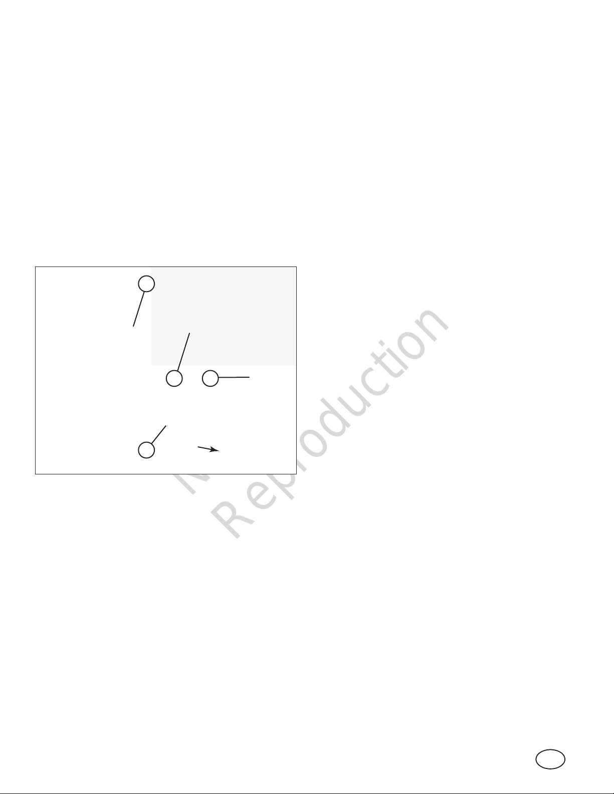
How To Remove The Battery
1. Raise the operator seat to gain access to the battery
compartment.
2. Disconnect the BLACK (Negative) cable (A, Figure 26)
from the negative battery terminal. Retain the mounting
hardware.
E
B
A
How To Charge The Battery
1. Remove the battery. Refer to “How To Remove The
Battery”.
2. Place the battery in a well-ventilated area.
3. Connect a 12-volt constant-voltage battery charger to
the battery terminals; RED to positive (+) and BLACK to
negative (-) terminal.
4. Charge the battery for 2 to 4 hours.
WARNING
The battery on this unit requires the use of a constant
voltage (CV) battery charger designed for valve regulated
(sealed) non-spillable batteries. Attempting to use a
standard battery charger may result in damage to the
battery. DO NOT use “BOOST” chargers on the battery.
DO NOT attempt to charge the battery while installed on
the unit.
How To Install The Battery
1. Raise the operator seat.
2. Install the battery (E, Figure 26) into the battery
compartment, orientating it in the wireform (D) as shown.
3. Secure the battery with the battery strap (C), hooking the
loose end onto the wireform.
4. Connect the RED positive (+) cables (B) to the positive
terminal (+) on the battery with the removed hardware.
5. Connect the black negative (-) cable (A) to the negative
terminal (-) on the battery with the removed hardware.
F
D
Figure 26
WARNING
Always disconnect the BLACK negative (-) cable first.
3. Disconnect the RED (Positive) cables (B) from the
positive battery terminal. Retain the mounting hardware.
4. Unhook one end of the battery strap (C) from the
wireform (D).
5. Carefully remove the battery (E).
WARNING
Always disconnect the BLACK negative (-) cable first.
C
6. Apply a small amount of grease over the terminals to
prevent corrosion.
7. Reinstall the positive terminal cover (F) over the positive
terminal.
WARNING
Always shield the positive terminal with the positive terminal cover.
21
Not for
Reproduction
How To Store The Battery
If the unit is to be stored out of season, it is recommended
the battery be removed, charged and stored.
1. Remove the battery. Refer to “How To Remove The
Battery”.
2. Charge the battery. Refer to “How To Charge The
Battery”.
3. Store the battery in an area away from the unit on a
wood surface. DO NOT STORE THE BATTERY ON A
CONCRETE SURFACE.
Storage
1. Thoroughly clean the unit by removing all grass
clippings and debris.
2. Perform maintenance and lubrication as required.
3. Drain the fuel from the fuel tank (unless using a fuel
stabilizer - Refer to “Fuel System”).
4. Start the engine and allow it to run until the engine runs
out of fuel. This allows the carburetor and fuel system to
remain clean during storage.
5. Remove and store the battery. Refer to “How To Store
The Battery”.
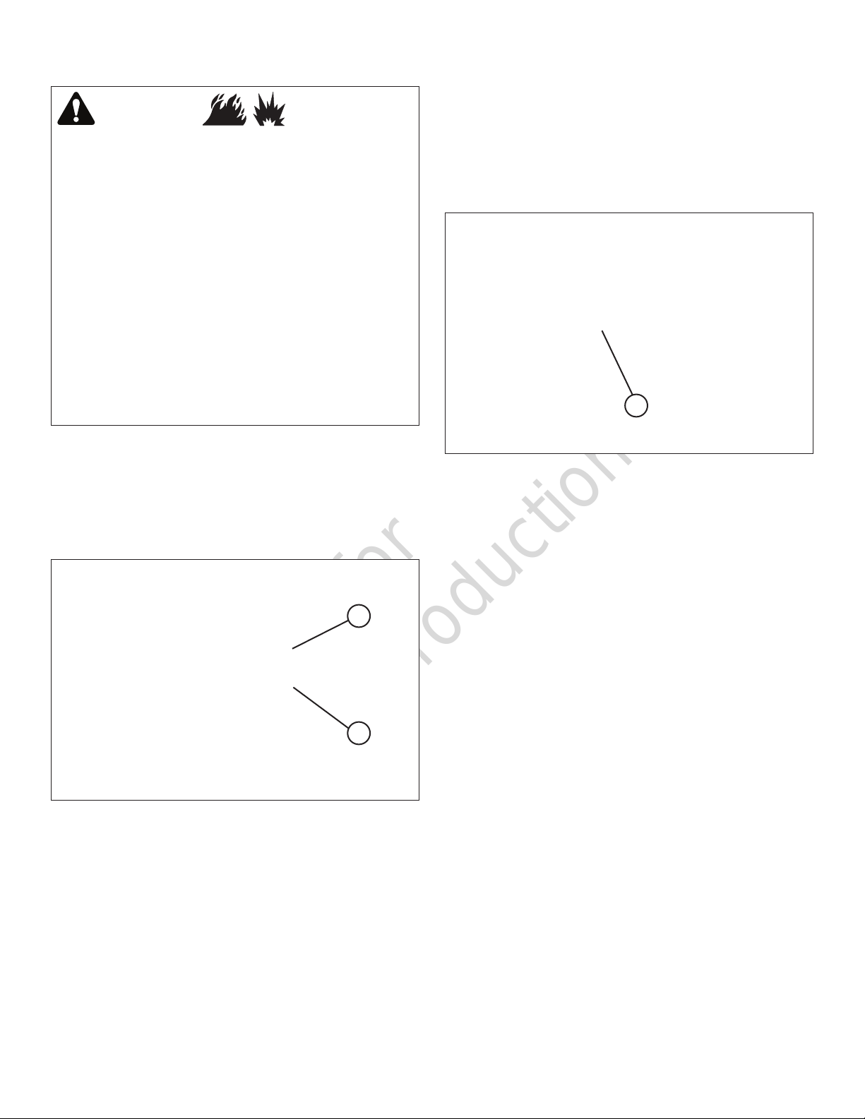
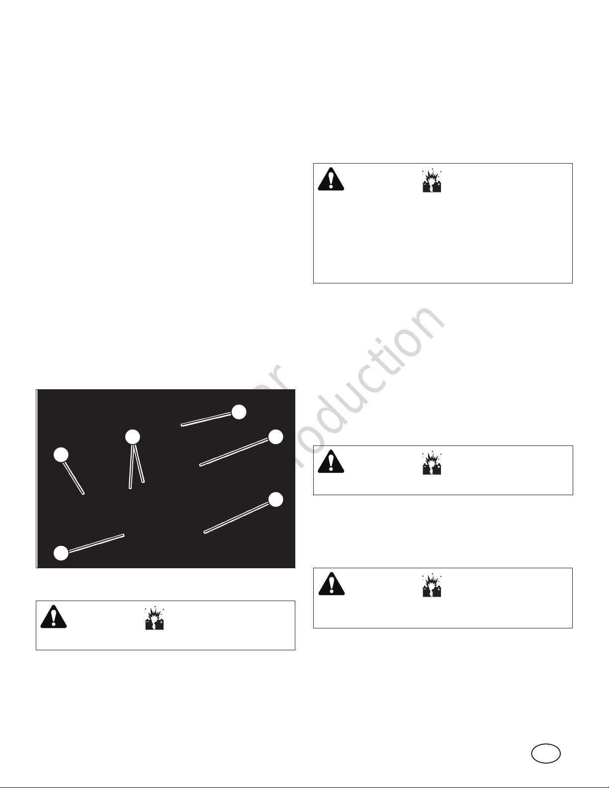
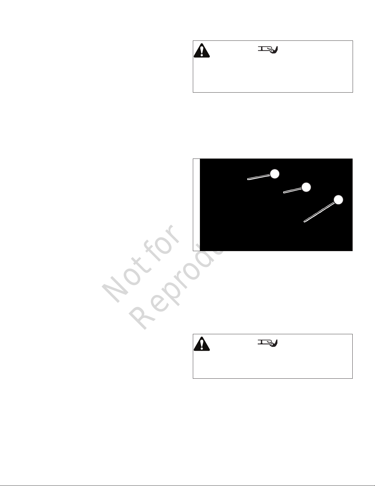
How To Inspect The Mower Blade
WARNING
Wear heavy leather gloves when handling or working
around cutting blades. Blades are extremely sharp and
can cause severe injury. DO NOT use a cutting blade that
shows signs of excessive wear or damage.
Inspect the blade frequently for signs of excessive wear or
damage (Figure 27):
(A) New blade;
(B) Wear limit (notch starts);
(C) Dangerous condition - do not use on mower! Replace
with new blade. Contact your authorized dealer.
A
B
C
Fuel System
Fuel can become stale when stored over 30 days. Stale fuel
causes acid and gum deposits to form in the fuel system
or on essential carburetor parts. To keep fuel fresh, use
Briggs & Stratton Advanced Formula Fuel Treatment
& Stabilizer, available wherever Briggs & Stratton genuine
service parts are sold.
There is no need to drain gasoline from the engine if a fuel
stabilizer is added according to instructions. Run the engine
for two (2) minutes to circulate the stabilizer throughout the
fuel system before storage.
If gasoline in the engine has not been treated with a fuel
stabilizer, it must be drained into an approved container.
Run the engine until it stops from lack of fuel. The use of a
fuel stabilizer in the storage container is recommended to
maintain freshness.
Engine Adjustments And Repairs
Engine adjustments and/or repairs should be performed by
an authorized dealer.
Rider Adjustments And Repairs
The following adjustment and repair items can be made by
the owner. However, it is recommended that they be made
by an authorized dealer.
Figure 27
How To Sharpen The Mower Blade
Contact an authorized dealerfor assistance regarding
mower blade sharpening.
How To Adjust The Mower Blade
Contact an authorized dealerfor assistance.
How To Level The Mower Deck
WARNING
Wear heavy leather gloves when handling or working
around cutting blades. Blades are extremely sharp and
can cause severe injury.
22
Not for
Reproduction
en
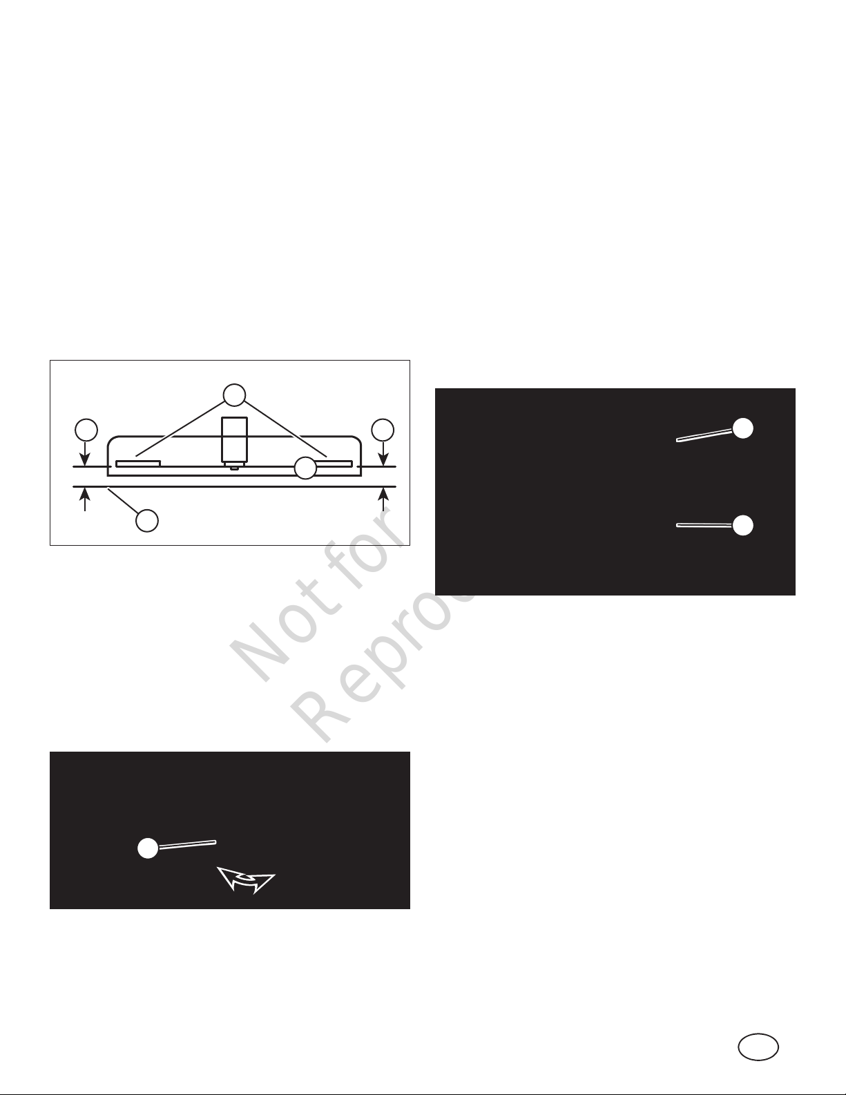
Side-To-Side Leveling
Before making deck leveling adjustments, check the tire
pressure. Refer to “How To Check Tire Pressure”. If tires are
properly inflated and mowing is still uneven, adjust side-toside deck leveling.
1. Place the unit on a smooth level surface.
2. Turn the engine off and remove the key. Remove the
spark plug wire from the spark plug and secure the wire
away from the plug.
3. Raise the mower deck to the highest cutting position.
4. Place a piece of angle iron, pipe, or similar object under
the rear center of the deck.
5. Lower the mower deck until the rear of the deck is
supported by the object placed under it in the previous
step. (The rear hanger rods (A, Figure 28) should be
loose.)
A
C
B
C
8. Raise the mower deck, and remove the angle iron, pipe,
or similar object.
9. Proceed to check front to rear leveling.
Front-to-Rear Leveling
NOTE: Perform side-to-side leveling first.
1. With the unit on a smooth, level surface, rotate the blade
until the blade tips are at the front and rear of the deck.
2. Measure the distance from the blade tips (A, Figure 28)
to the floor (B). The distance (C) should be the same,
or the rear 1/8” to 1/4” (3 - 6mm) lower than the front.
If the rear blade tip is higher than the front, or is more
than 1/4” (6mm) lower than the front, proceed with
adjustment.
3. If adjustment is needed, turn the lock nut (B, Figure 30)
on both left and right hanger rods (A) the same number
of rotations to raise or lower the rear of the deck.
B
B
Figure 28
6. Wearing heavy leather gloves, rotate the blade until the
blade tips are positioned at the right and left sides of
the mower deck. Measure the distance from the blade
tips (A, Figure 28) to the floor (B). If the measurement
(C) is within 1/8” (3mm) from side-to-side, the deck
is considered level. If difference from side-to-side is
greater than 1/8” (3mm), continue with adjustment.
7. If adjustment is needed, slowly turn the eccentric (A,
Figure 29) on the left front lift arm until the blade tips are
within 1/8” (3mm) of each other.
A
A
Figure 30
4. Measure the blade tips again.
5. Repeat Steps 2 through 4 until proper leveling is
obtained.
How To Adjust The Brake / Parking Brake
Contact an authorized dealer for assistance.
How To Adjust Mower Blade Belt Tension
Contact an authorized dealer for assistance.
How To Adjust The Blade Brake
Contact an authorized dealer for assistance.
Figure 29
23
 Loading...