

Page 1
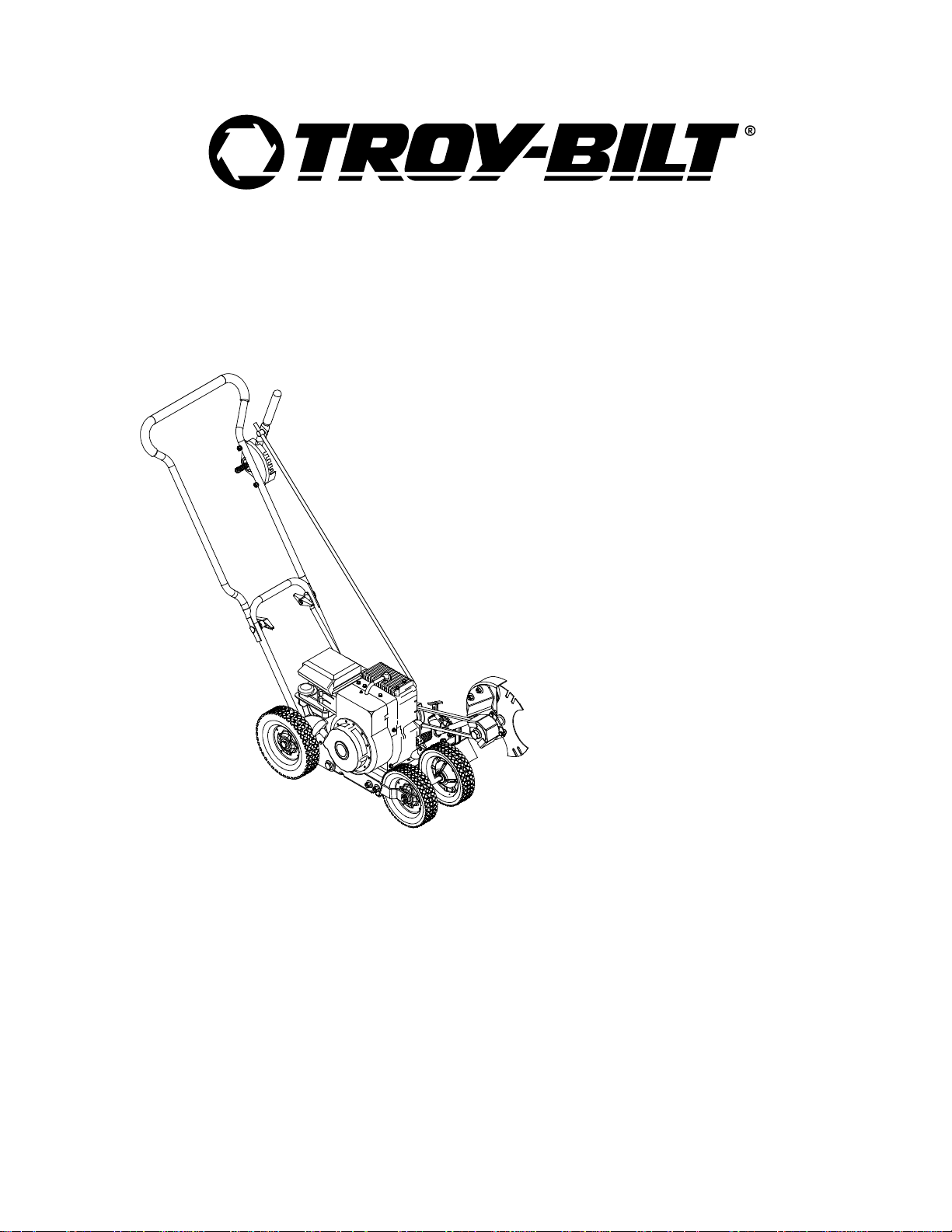
OPERATOR’S MANUAL
Edger
Model 592
IMPORTANT: READ SAFETY RULES AND INSTRUCTIONS CAREFULLY
Warning: This unit is equipped with an internal combustion engine and should not be used on or near any unimproved forest-
covered, brush-covered or grass-covered land unless the engine’s exhaust system is equipped with a spark arrester meeting
applicable local or state laws (if any). If a spark arrester is used, it should be maintained in effective working order by the operator.
In the State of California the above is required by law (Section 4442 of the California Public Resources Code). Other states may have
similar laws. Federal laws apply on federal lands. A spark arrester for the muffler is available through your nearest engine authorized
service dealer or contact the service department, P.O. Box 361131 Cleveland, Ohio 44136-0019.
TROY-BILT LLC P.O. BOX 361131 CLEVELAND, OHIO 44136-0019
PRINTED IN U.S.A.
FORM NO.
769-00044.fm
(12/01)
Page 2

TABLE OF CONTENTS
Content Page
Important Safe Operation Practices...................................................................3
Assembling The Edger.......................................................................................5
Know The Edger.................................................................................................6
Operating The Edger..........................................................................................7
Making Adjustments...........................................................................................8
Maintaining and Servicing The Edger.................................................................10
Troubleshooting ................................................................................................12
Parts List ............................................................................................................13
Warranty Information..........................................................................................Back Cover
FINDING MODEL NUMBER
This Operator’s Manual is an important part of your new edger. It will help you assemble, prepare and maintain the
unit for best performance. Please read and understand what it says.
Before you start assembling your new equipment, please locate the model plate on the
equipment and copy the information from it in the space provided below. The information on the
model plate is very important if you need help from your your dealer or the MTD Customer Support
department.
•You can locate the model number by looking on the surface of the base plate in the rear of the edger.
A sample model plate is explained below. For future reference, please copy the model number and the serial
number of the equipment in the space below.
Copy the model number here:
Copy the serial number here:
ENGINE INFORMATION
The engine manufacturer is responsible for all engine-related issues with regards to performance, power-rating,
specifications, warranty and service. Please refer to the engine manufacturer’s Owner’s/Operator’s Manual packed
separately with your unit for more information.
CALLING CUSTOMER SUPPORT
If you have difficulty assembling this product or have any questions regarding the controls, operation or
maintenance of this unit, please call the Customer Support Department.
Call 1- (330) 558-7220 or 1- (866)-840-6483 to reach a Customer Support representative. Please
have your unit’s model number and serial number ready when you call. See previous section to locate
this information. You will be asked to enter the serial number in order to process your call.
For more details about your unit, visit our website at www.troybilt.com
2
Page 3

SECTION 1: IMPORTANT SAFE OPERATION PRACTICES
WARNING: THIS SYMBO L POINTS OUT IMPORT ANT SAFETY INSTRUC TIONS WHICH, IF NO T
FOLLOWED, COULD ENDANGER THE PERSONAL SAFETY AND/OR PROPERTY OF YOURSELF
AND OTHERS. READ AND FOLLOW ALL INSTRUCTION S IN THIS MA NUAL B EFORE ATTEMP TING
TO OPERATE THIS MACHINE. FAILURE TO COMPLY WITH THESE IN STRUCTIONS MAY RESULT
IN PERSONAL INJURY. WHEN YOU SEE THIS SYMBOL — HEED ITS WARNING.
WARNING: The Engine Exhau st from this product con tains chemica ls known to the
State of California to cause cancer, birth defects or other reproductive harm.
DANGER: This machine wa s built t o be opera ted acco rding to t he rules for safe o peration i n this m anual. As with
any type of power equipment, carelessness or error on the part of the operator can result in serious injury.
If you violate any of these rules, you may cause serious injury to yourself or others.
TRAINING
1. Read, understand, and follow all instructions on the
machine and in the manual(s) before attempting to
assemble and operate. Keep this manual in a safe
place for future and regular reference and for
ordering replacement parts.
2. Be familiar with all controls and their proper
operation. Know how to stop the machine and
disengage them quickly.
3. Never allow children under 14 years old to operate
this machine. Children 14 years old and over
should read and understand the operation
instructions and safety rules in this manual and
should be trained and supervised by a parent.
4. Never allow adults to operate this machine without
proper instruction.
5. To help avoid blade contact or a thrown object
injury, keep bystanders, helpers, children and pets
at least 75 feet from the machine while it is in
operation. Stop machine if anyone enters the area.
PREPARATION
1. Thoroughly inspect the area where the equipment
is to be used. Remove all stones, sticks, wire,
bones, toys and other foreign objects which could
be tripped over or picked up and thrown by the
blade. Thrown objects can ca use seriou s persona l
injury.
2. Always wear safety glasses or safety goggles
during operation and while performing an
adjustment or repair to protect your eyes. Thrown
objects which rico chet can cause se rious injury to
the eyes.
3. Wear sturdy, rough-soled work shoes and closefitting slacks and shirts. Shirts and pants that cover
the arms and legs and steel-toed shoes are
recommended. Never operate this machine in bare
feet, sandals, slippery or light weight (e.g. canvas)
shoes.
4. Never attempt to make any adjustments while the
engine is running, except where specifically
recommended in the operator’s manual.
5. To avoid personal injury or property damage use
extreme care in handling gasoline. Gasoline is
extremely flammable and the vapors are explosive.
Serious personal injury can occur when gasoline is
spilled on yourself or your clothes which can ignite.
Wash your skin and change clothes immediately.
a. Use only an approved gasoline container.
b. Extinguish all cigarettes, cigars, pipes and
other source s of i gnitio n.
c. Never fuel machine indoors.
d. Never remove gas cap or add fuel while the
engine is hot or running.
e. Allow engine to cool at least two minutes
before refueling.
f. Never over fill fuel tank. Fill tank to no more
than ½ inch below bottom of filler neck to
provide space for fuel expansion.
g. Replace gasoline cap and tighten securely.
h. If gasoline is spilled, wipe it off the engine
and equipment. Move unit to another area.
Wait five minutes before starting the engine.
i. Never store the machine or fuel container
inside where there is an open flame, spark or
pilot light as on a water heater, space heater,
furnace ,clothes dryer or other gas
appliances.
j. Allow machine to cool at least 5 minutes
before storing.
OPERATION
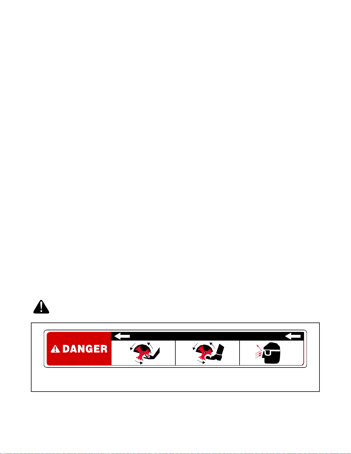
1. Do not put hands or feet near rotating parts.
Contact with the rotating blade can amputate hands
and feet.
2. The blade control handle is a safety device. Never
bypass its operation. Doing so, makes the machine
unsafe and may cause personal injury.
3. Never operate without blade guard, debris shield
and blade control handle in place and working.
3
Page 4
4. Never operate with damaged safety devices.
Failure to do so, can result in personal injury.
5. Never run an engine indoors or in a poorly
ventilated area. Engine exhaust contains carbon
monoxide, an odorless and deadly gas.
6. Do not operate machine while under the influence
of alcohol or drugs.
7. Muffler and engine become hot and can cause a
burn. Do not touch.
8. Never operate this machine without good visibility
or light. Always be sure of your footing and keep a
firm hold on the handles. Walk, never run.
9. Do not operate this machine if it has been dropped
or damaged. Return machine to your nearest
authorized servicing dealer for examination and
repair.
10. Do not operate this machine with a damaged or
excessively worn cutt ing bl ade.
11. Never attempt to clear material from the blade
guard while the engine is running. Shut the engine
off, disconnect the spark plug wire and ground
against the engine to prevent unintended starting.
12. Do not overload machine capacity by attempting to
edge at too fast of a rate.
13. Stay alert for uneven sidewalks, terrain etc. Always
push slowly over rough surfaces. Do not use this
machine on gravel surfaces.
14. Do not operate machine in rain or wet soil
conditions.
15. Always operate machine from behind the handles
and position yourself where the direct line of sight
to cutting blade is blocked by guards.
16. Always stop engine when edging or trimming is
delayed or when transporting machine from one
location to another.
17. Never leave a running machine unattended. Stop
the engine, disconnect spark plug wire and ground
against the engine to prevent unintended starting.
18. Only use parts and accessories made for this
machine by th e manufact urer. Fa ilure to do so, can
result in personal injury.
19. If situations occur which are not covered in this
manual, use care and good judgment. Contact an
authorized MTD service dealer or telephone 1-800800-7310.
MAINTENANCE AND STORAGE
1. Never tamper with safety devices. Check t heir
proper operation regularly.
2. Before cleaning, repairing, or inspecting,
disconnect the spark plug wire and ground against
the engine to prevent unintended starting.
3. Check bolts, and screws for proper tightness at
frequent intervals to keep the machine in safe
working condition. Also, visually inspect machine
for any damage.
4. Do not change the engine governor setting or overspeed the engine. The governor controls the
maximum safe operating speed of the engine.
5. The blade, blade guard and debris shield are
subject to wear and damage. For your safety
protection, frequently check all components and
replace with original equipment manufacturer’s
(O.E.M.) parts only. “Use of parts which do not
meet the original equipment specifications may
lead to improper performance and compromise
safety!”
6. Maintain or replace safety and instruction labels, as
necessary.
7. Observe proper disposal laws and regulations for
gas, oil, etc. to protect the environment.
8. Never store the machine or fuel container inside
where there is an open flame, spark or pilot light
such as a water heater, furnace ,clothes dryer etc.
Always refer to the o perator’s manual f or prope r
9.
instructions on off-sea son storage.
WARNING: YOUR RESPONSIBILITY
Restrict the use of this power machine to persons who read, understand and follow the warnings
and instructions in this manual and on the machine.
KEEP AWAY — ROTATING BLADE
Figure 1
4
Page 5

SECTION 2: ASSEMBLING YOUR EDGER
IMPORT ANT :
This unit is shipped WITHOUT
GASOLINE or OIL. After setting up the unit, service
engine with gasoline and oil as instructed in the Briggs
& Stratton Owner/Operator Manual packed with your
edger.
NOTE: Reference to right or left hand side of the edger
is observed from the operating position.
Contents of Carton
One Edger Assembly
One Plastic Bag Containing:
Edger Operator’s Manual
Registration Card
Engine Owner’s Guide
One Clutch Rod (747-1164) with
One Ferrule (711-0392)
Two Flat Washers (736-0264) and
Two Hairpin Clips (714-0104) in place
Grounding the Engine’s Spark Plug
• Disconnect the spark plug wire from the spark plug
and ground it on the top of the engine by placing its
rubber boot snugly over a bolt head. See Figure 2.
Rubber Boot
Spark Plug Wire
Wing Knobs
Upper Handle
Lower Handle
Figure 3
• Remove the flat washer and hairpin clip from the
ferrule found on the upper portion of the clutch rod.
Save this hardware as it will be reinserted.
• Insert the ferrule located on the upper portion of the
clutch rod into the hole on the blade clutch/depth
control lever. Secure with the flat washer and
hairpin clip removed earlier. See Figure 4.
Blade Clutch /
Depth Control Lever
Bolt Head
Figure 2
Positioning the Edger Handles
• Remove and discard any packaging cardboard that
may be present between the upper handle and the
lower handle.
• Pivot the upper handle upward until it snaps into
place.
• Tighten the wing knobs which are located on both
the left and right sides of the handle. See Figure 3.
Ferrule
Flat Washer
Clutch Rod
Hairpin Clip
Figure 4
• Remove the flat washer and hairpin clip from the
lower portion of the clutch rod. Save this hardware
as it will be reinserte d.
• Insert the lower end of the clutch rod into the hole in
the pivot arm found on the left side of the edger.
• Secure with the flat washer and hairpin clip
removed earl ier. See F igure 5.
5
Page 6

Hairpin Clip
Flat Washer
Clutch Rod
Pivot Arm
• Disconnect the spark plug wire and ground it as
instructed earlier in this se ction. Refer to Figure 2.
• With the blade clutch/depth control lever in the
disengaged position (the top notch in the depth
adjustment bracket), carefully pull the recoil starter
rope. The blade on the edger should not turn. If the
blade turns, remove the ferrule from the blade
clutch/depth control lever by first removing the
hairpin clip and flat washer.
• Rotate the ferrule clockwise one or two turns on the
clutch rod, then re-insert the ferrule into the lever
and recheck the adjustment.
• After adjusting, check to be certain the blade clutch/
depth control lever can be moved to the furthest
notch forward without bowing the clutch rod. If it
can’t, recheck the adj ustme nt.
Figure 5
IMPORT ANT :
operating the edger.
Perform the clutch rod adjustment before
Clutch Rod Adjustment
Before operating the edger, check the adjustment of the
clutch rod as follows:
SECTION 3: KNOW THE EDGER
Throttle Control
The throttle control lever is located on the engine. It can
be adjusted to regulate the engine speed only.
NOTE: Refer to the Br iggs & Stratton Owner/Oper ator
Manual packed with your edger for a detailed
description of all engine-related controls and
components.
Choke Control
The choke control lever is located on the engine. It is
used to aid in starting a cold engine.
NOTE: Refer to the Br iggs & Stratton Owner/Oper ator
Manual packed with your edger for a detailed
description of all engine-related controls and
components.
Blade Clutch / Depth Contr ol Lever
The blade clutch/depth control lever is located on the
right side of the upper handle. It is used to engage and
disengage the edger blade. It is also used to control the
depth of the cut. The further forward the control lever is
moved, the deeper into the soil the edger blade will cut.
IMPORT ANT :
both ends with a flat washer and hairpin clip before
operating the edger.
Be certain that the clutch rod is secured at
WARNING: When o perating the edger, stop
engine immediately and readjust the clutch
rod if the blade turns with the blade clutch/
depth control lever in the disengaged position.
Pull Rope / Recoil Starter
The pull rope/recoil starter is used to start the engine.
NOTE: Refer to the Br iggs & Stratton Owner/Oper ator
Manual packed with your edger for a detailed
description of all engine-related controls and
components.
Blade Angle Adjustment Lever
The blade angle adjustment lever is located on the
front, left portion of the edger, behind the edger blade. It
is used to vary the angle of the edger blade between
one of ei ght p ositi ons f rom tr enchi ng to trimm ing.
Curb Height Adjustment Lever
The curb height adjustment lever is found on the rear,
right portion of the edger. It aids in stabilizing the edger
operating along a curb.
IMPORT ANT :
before operating the edger.
Become familiar with all the controls
6
Page 7

Throttle Control &
Choke Control
Curb Height
Adjustment Lever
Pull Rope / Recoil Starter
Figure 6
SECTION 4: OPERATING THE EDGER
WEAR YOUR
SAFETY GLASSES
FORESIGHT IS BETTER
THAN NO SIGHT
Adding Gasoline And Oil
Service the engine with gasoline and oil as instructed in
the Briggs & Strat ton Owner/Operator Manual packed
with your edger. Read instructions carefully.
The operation of any edger can result
in foreign objects being thrown into
the eyes, which can result in severe
eye damage. Always wear safety
glasses or eye shields. We
recommend wide vision safety mask
for over spectacles or standard
safety glasses
WARNING: Do not lower blade if blade is
over concrete, asphal t, rocks or the like. The
blade can strike the supporting surface,
resulting in personal injury or property
damage.
WARNING: Never fil l fuel tank indoors, with
engine running or un til the engine has been
allowed to cool for at least two minute s after
running.
Blade Clutch /
Depth Control Lever
Blade Angle
Adjustment Lever
To start the edger’s engine, proceed as follows:
• Attach the spark plug wire to the spark plug. Make
certain the metal cap on the end of the spark plug
wire is fastened securely over the metal tip on the
spark plug.
• Move the blade clutch/depth control lever back to
the disengaged position, and place it in the
adjacent (top) notch.
• Move the choke control lever on the engine into the
CHOKE or START position.
• Move the throttle control lever on the engine into
the FAST (Rabbit) position.
• Grasp the starter handle and slowly pull the rope
outward until engine reaches the start of its
compression cycle (the rope will pull slightly harder
at this point).
• After slowly allowing the rope to recoil, pull the rope
with a rapid, continuous, full arm stroke. Keep a firm
grip on starter handle throughout the entire stroke.
• Allow the starter handle to slowly recoil into the
engine.
• Slowly move the choke control lever on the engine
into the RUN position after the engine has started.
Starting The Eng ine
NOTE: Refer to the Br iggs & Stratton Owner/Oper ator
Manual packed with your edger for a detailed
description of all engine-related controls and
components.
Stopping The Engine
To stop the edger’s engine, proceed as follows:
• Move the blade clutch/depth control lever back to
the disengaged position, and place it in the
adjacent (top) notch.
7
Page 8

• Move the throttle control lever on the engine into
the STOP or OFF position.
IMPORT ANT :
wire is properly grounded as instructed in SECTION 2:
Assembling The Edger before storing the edger for its
next use. Refer to Figure 2.
Make certain that the engine’s spark plug
Engaging the Edger Blade
WARNING: The blade clutch/depth control
lever is designed to minimize the risk of blade
contact injury. Do not under any
circumstances attempt to defeat the function
of the blade clutch/de pth control, or use the
edger if the control is not adjusted properly.
WARNING: Keep hands and feet away from
edger blade wheneve r the engine is running ,
whether blade is engaged or disengaged.
The blade clutch/depth control lever has two main
functions:
1. To engage and disengage the blade.
2. To control the depth of cut.
To disengage the blade, proceed as follows:
• Move the blade clutch/depth control lever to the left
and place it in the top notch in the depth adjustment
bracket. See Figure 7.
Blade Clutch /
Depth Control Lever
Depth Adjustment
Bracket
Figure 7
To engage the blade, proceed as follows:
• Move the control lever to the left and place it into
any of the five lower notches. The further forward
the blade clutch/depth control lever is moved, the
deeper or lower the blade will cut into the ground.
SECTION 5: MAKING ADJUSTMENTS
Front Wheel Adjustment
WARNING: Always place the blade clutch/
depth control lever in the DISENGAGED
position and turn the edger’s engine off before
performing any adjustments.
Before operating the edger with the blade in the
trimming (horizontal) position, it is necessary to alter
the position of the front, left wheel.
When operating the edger with the curb wheel lowered,
it is necessary to alter the position of the front, right
wheel. To do either, proceed as follows:
• To change position of the front, left wheel, remove
the hairpin clip on the left. To change position of the
front, right wheel, remove the hairpin clip on the
right. Se e Figure 8.
• Reposition the wheel by sliding it down the front
axle toward the opposite wheel. See Figure 8.
• Secure the whee l in its new loca tion by inserti ng the
hairpin clip removed earlier in the hole found
immediately adjacent to it. See Figure 8.
Hairpin Clips
Holes
Figure 8
8
Page 9

Edger Blade Angle Adjustment
WARNING: Rotating cutting blade may throw
objects causing personal injury. Keep area
clear of bystanders and do not operate
without guards in place.
The cutting blade can be adjusted to eight positions. To
adjust the blade angle, proceed as follows:
• Place the blade clutch/depth control lever in the
disengaged position (top notch).
WARNING: Always place the blade clutch/
depth control lever in the DISENGAGED
position before adjusting the blade angle.
• Pull forward on the blade angle adjustment lever
before rotating the spindle assembly.
• Release the blade angle adjustment lever into one
of the notches on the pivot bracket. See Figure 9.
Blade Angle
Adjustment Lever
Spindle Assembly
Pivot Bracket
Edging
Placing the blade angle adjustment lever in the second
notch from the right will put the spindle assembly at a
90° angle for vertical edging as illustrated in Figure 11.
Figure 11
Beveling
Placing the blade angle adjustment lever in the third,
fourth, fifth, sixth or seventh notch (from the right) will
put the spindle assembly at various angles for beveling
with the edger as illustrated in Figure 12.
IMPORT ANT :
counter-clockwise (putting the blade closer to a
horizontal position), it IS necessary to change the
position of the front, left wheel to prevent the edger
blade from striking the wheel. See Front Wheel Adjustment
earlier in this section.
When the spindle assembly is rotated
Figure 9
Trenching
Placing the blade angle adjustment lever in the notch
furthest to the right will put the spindle assembly at a
proper angle for trenching with the edger as illustrated
in Figure 10.
Figure 10
Figure 12
WARNING: Always place the blade clutch/
depth control lever in the DISENGAGED
position before adjusting the blade angle.
9
Page 10

Trimming
Placing the blade angle adjustment lever in the notch
furthest to the left will put the spindle assembly at a
proper angle for trimming with the edger as illustrated in
Figure 13.
IMPORT ANT :
counter-clockwise (putting the blade closer to a
horizontal position), it IS necessary to change the
position of the front, left wheel to prevent the edger
blade from striking the wheel. See Front Wheel Adjustment
earlier in this section.
When the spindle assembly is rotated
To adjust the height of the curb wheel, proceed as
follows:
• Perform the Front Wheel Adjustment for curb wheel
operation as instructed earlier in this section.
• Lower the right, rear wheel by moving the curb
height adj ustme nt le ver sli ghtl y to t he lef t.
• Place the right, rear wheel into an applicable
position in rel ation to t he he ight of th e curb to be
edged along.
• Release the curb height adjustment lever to lock
the wheel in position. See Figure 14.
Figure 13
Curb Wheel Adjustment
The right, rear wheel of the edger can be lowered into
one of five positions to ease the task of edging along a
curb.
SECTION 6: MAINTAINING & SERVICING THE EDGER
WARNING: Disconnect the spark plug wire
and ground against the engine before
performing any adjustment, repairs or
maintenance. Refer to Figure 2.
Lubrication
Engine
Refer to the Service, Storage & Specifications section of the
Briggs & Stratton Owner/Operator Manual packed with
the edger for all engine-related service specifications.
Wheels & Front Axle
Lubricate the wheels and front axle at least once a
season with a light oil. Also if the wheels are removed
for any reason, lubricate the surface of the axle bolt and
the inner surface of the wheel with light oil.
Pivot Points
Lubricate the pivot points on the blade angle
adjustment lever, blade clutch/depth control lever and
curb height adjustment le ver with ligh t oil at least once a
season.
Cutting Head Bearings
The two ball bearings in the blade spindle housing are
lubricated and sealed at the factory and require no
lubrication.
Spindle Shaft
Lubricate the two shoulder spacers and the entire area
surrounding the compression spring on the edger’s
spindle sh aft wi th li ght o il (NO T WD-40) frequently
during th e seas on. Do NOT allow r ust to for m in this
area. See Figure 15.
Figure 14
10
Page 11

Shoulder Spacer
Compression Spring
• Remove the blade spindle belt guard by removing
the hex screws, two lock washers and two hex nuts
which secure it to the blade spindle plate. See
Figure 17.
Blade Spindle Plate
Figure 15
Replacing the Edger Blad e
• Use two wrenches (one wrench to prevent the hex
bolt head from spinning and the other to remove the
hex lock nut) to remove the edger blade. See
Figure 16.
Bell Washer
Hex Bolt Head
Hex Lock Nut
Figure 16
• Remove and discard the edger blade but retain the
bell washer and hex lock nut.
• Install the replacement edger blade, the bell
washer (cupped side facing inward) and the hex
lock nut removed earlier.
IMPORT ANT :
Use a torque wrench to tighten the hex
lock nut to between 37 foot-lbs. and 50 foot- lbs.
Replacing the Drive Belt
The edger drive belt is subject to wear and should be
replaced if any signs of cracking, shredding or rotting
are present. To replace the belt, proceed as follows:
• Place the blade angle adjustment lever in the
edging position. Refer to Figure 11.
Blade Spindle
Belt Guard
Hex Screws
Figure 17
• Remove the belt from around the blade spindle
pulley.
• Place the blade clutch/depth control lever in the
lowest notch (all the way forward).
• Remove the engine pulley belt guard by removing
the two hex screws and two lock wa shers which
secure it to the engine block. See Figure 18.
Hex
Engine Pulley
Belt Guard
Screws
Figure 18
• Remove the belt from around the engine pulley.
• Install the replacement drive belt around both the
blade spindle pulley and the engine pulley.
• Reattach the blade spindle belt guard to the blade
spindle plate with the hardware removed earlier.
• Reattach the engine pulley belt guard to the engine
block with the hardware removed earlier.
WARNING: Never operate the edger wit hout
both the blade spindle belt guard and the
engine pulley belt guard in place.
11
Page 12

Off-Season Storage
Observe the following when preparing the edger for
long-term storage:
• Clean and lubricate unit thoroughly as instructed on
page 10 of this manual.
• Refer to the Service, Storage & Specifications section of
the Briggs & Strat ton Owner/Operator Manual
packed with the edger for engine storage
instructions.
• Coat the edger blade with chassis grease to
prevent rusting and corrosion.
• Store the edger in a dry, clean area. Do not store
next to any corrosive materials, such as lawn
fertilizer.
• Coat the edger, especially any springs and
bearings with a light oil or silicone spray.
IMPORT ANT :
equipment in an poorly ventilated or metal storage
shed, care should be taken to rustproof the equipment.
SECTION 7: TROUBLESHOOTING
Trouble Possible Cause(s) Corrective Action
Engine fails to start Dirty air cleaner
Engine needs to be primed
Fuel tank e mpty
Stale fuel in gasoline tank
Throttle control lever not in
starting position
Spark plug wire disconnected.
Spark plug fouled
Engine flooded
Engine runs erratic Spark plug wire loose
Stale fuel in gasoline tank
Vent in gas cap plugged
Water or dirt in fuel system
Dirty air cleaner
Carburetor out of adjustment
Engine overheats Engine oil level low
Air flow restric ted
Dirty air filter
Carburetor not adjusted properly
Excessive vibration Edger blade bent or damaged
Blade spindle bent or damaged
Drive belt slips Belt worn or stretched Replace drive belt.
Refer to the Briggs & Stratton Owner/Operator Manual
packed with your unit.
Push primer bulb two or three times.
Fill tank with clean, fresh gasoline.
Drain gasoline and refill tank with clean, fresh gasoline.
Move throttle lever to FAST position.
Connect the spark plug wire to the spark plug.
Clean, adjust gap or replace spark plug.
Refer to the Briggs & Stratton Owner/Operator Manual
packed with your unit.
Connect and tighten spark plug wire.
Drain gasoline and refill tank with clean, fresh gasoline.
Clear vent of any debris.
Drain fuel tank. Refill with fresh fuel.
Refer to the Briggs & Stratton Owner/Operator Manual
packed with your unit.
Refer to the Briggs & Stratton Owner/Operator Manual
packed with your unit.
Fill crankcase with proper oil.
Clean the area around the engine’s cooling fins.
Replace the engine’s air filter
Refer to the Briggs & Stratton Owner/Operator Manual
packed with your unit.
Replace edger blade.
Contact an authorized MTD service dealer.
When storing a ny type of po wer
12
Page 13

MANUFACTURER’S LIMITED WARRANTY FOR:
The limited warranty set forth be low is given by T roy-Bilt LL C
with respect to new merchand ise purch ased and used in the
United States, its possess ions and territor ies.
Troy-Bilt LLC warrants this produ ct again st defect s for a
period of two (2) yea rs co mmencing o n the date of ori ginal
purchase and will, at its option, repair or replace, free of
charge, any part foun d to be de fective in materi als or
workmanship. Thi s limite d warranty s hall onl y apply if thi s
product has been operated and ma intained in acco rdance
with the Operator’s Manu al furn ished with the produ ct, and
has not been sub ject to m isuse, abu se, com mercial use,
neglect, accident, i mproper m aintenan ce, altera tion,
vandalism, theft, fire, wa ter, or damage beca use of other peril
or natural disaste r. Dama ge resul ting from the insta llation o r
use of any accessory or attachmen t not approved b y Troy-Bilt
LLC for use with t he produc t(s) cove red by thi s manua l will
void your warrant y as to any resultin g damag e.
Normal wear parts or c omponen ts thereof are subj ect to
separate terms as fo llows: All normal wear parts or
component failures wil l be covered on the product for a period
of 90 days regardless of cause. After 90 days, but within the
two year period, norm al wear pa rt failures will be covered
ONLY IF caused by de fects in material s or workm anship o f
OTHER component pa rts. Norm al wear pa rts and
components includ e, but are not lim ited to: batt eries, belts,
blades, blade adapters, gras s bags, rider deck wheels, seats,
snow thrower skid shoes, sh ave plat es, au ger spiral rubber,
and tires.
HOW TO OBTAIN SERVICE: Warranty service is available,
WITH PROOF OF PURCHASE, through your local authorized
service dealer. To locate the deal er in you r area, ch eck your
Yellow Pages, or con tact Troy -Bilt LLC at P.O. Box 3 61131,
Cleveland, Ohio 441 36-0019, o r call 1-8 66-840- 6483 or 1330-558-7220, or lo g on to o ur Web si te at www .troybil t.com.
This limited warranty does not provide cover age in the
following case s:
a. The engine or component parts thereof. These ite ms
carry a separate manu facturer ’s warranty. Refe r to
applicable manufac turer’s warranty for terms a nd
conditions.
b. Log splitter pump s, valve s, and c ylinders have a sepa
rate one year war ranty.
c. Routine maintenance items su ch as l ubricants, fi lters,
blade sharpening , tune-ups, br ake adjustm ents, clutc h
adjustments, deck adj ustments, and norma l
deterioration of the exterior finish due t o use or
exposure.
d. Troy-Bilt LLC does not extend a ny warranty for
products sold or exported ou tside of the U nited States ,
its possesions an d territo ries, ex cept thos e sold
through Troy-Bilt LLC’s a uthorized channel s of exp ort
distribution.
e. Parts that are not genuin e Troy-Bilt parts are not
covered by this warranty.
f. Service completed by someone o ther than a n
authorized service d ealer is not cove red by thi s
warranty.
g. Transportation charges and service calls are not
covered.
No implied warranty, including any implie d warranty of
merchantability of fitness for a particular purpose,
applies after the applicable period of express written
warranty above as to the parts a s identified. No other
express warranty, w hether written or oral, e xcept as
mentioned above, given by any pe rson or entity,
including a dealer or reta iler, with respect to any product,
shall bind Troy-Bilt LLC. During the period of the
warranty, the exclusive reme dy is repai r or replace ment
of the product as set forth above.
The provisions as set forth in this warranty prov ide the
sole and exclusive rem edy arising from the sale. TroyBilt LLC shall not be liable for incidental or co nsequential
loss or damage including , without limita tion, expens es
incurred for substitute or rep lacement lawn care ser vices
or for rental expenses to temporarily replace a warra nted
product.
Some states do not allow the exclusion or limitation of
incidental or cons equentia l damage s, or lim itations on how
long an implied warranty lasts, so the above exclusions or
limitations may not apply to you.
In no event shall recovery of any kind be greater than the
amount of the purch ase pric e of the p roduct sold. Alteration
of safety features of the product shall void this w arranty.
You assume the risk and liability for loss, damage, or injury to
you and your prope rty and/or to others and their property
arising out of the misuse or i nability to use th e produc t.
This limited warrant y shall not extend t o anyone other than
the original purchaser or to the person for whom it was
purchased as a gift.
HOW STATE LAW RELATES TO THIS WARRANTY: This
limited warranty giv es you specific legal ri ghts, and you may
also have other rights w hich vary from state to state.
Troy-Bilt LLC, P.O. BOX 361131 CLEVELAND, OHIO 44136-0019; Phone: 1-866-840-6483, 1-330-558-7220
 Loading...