

Page 1
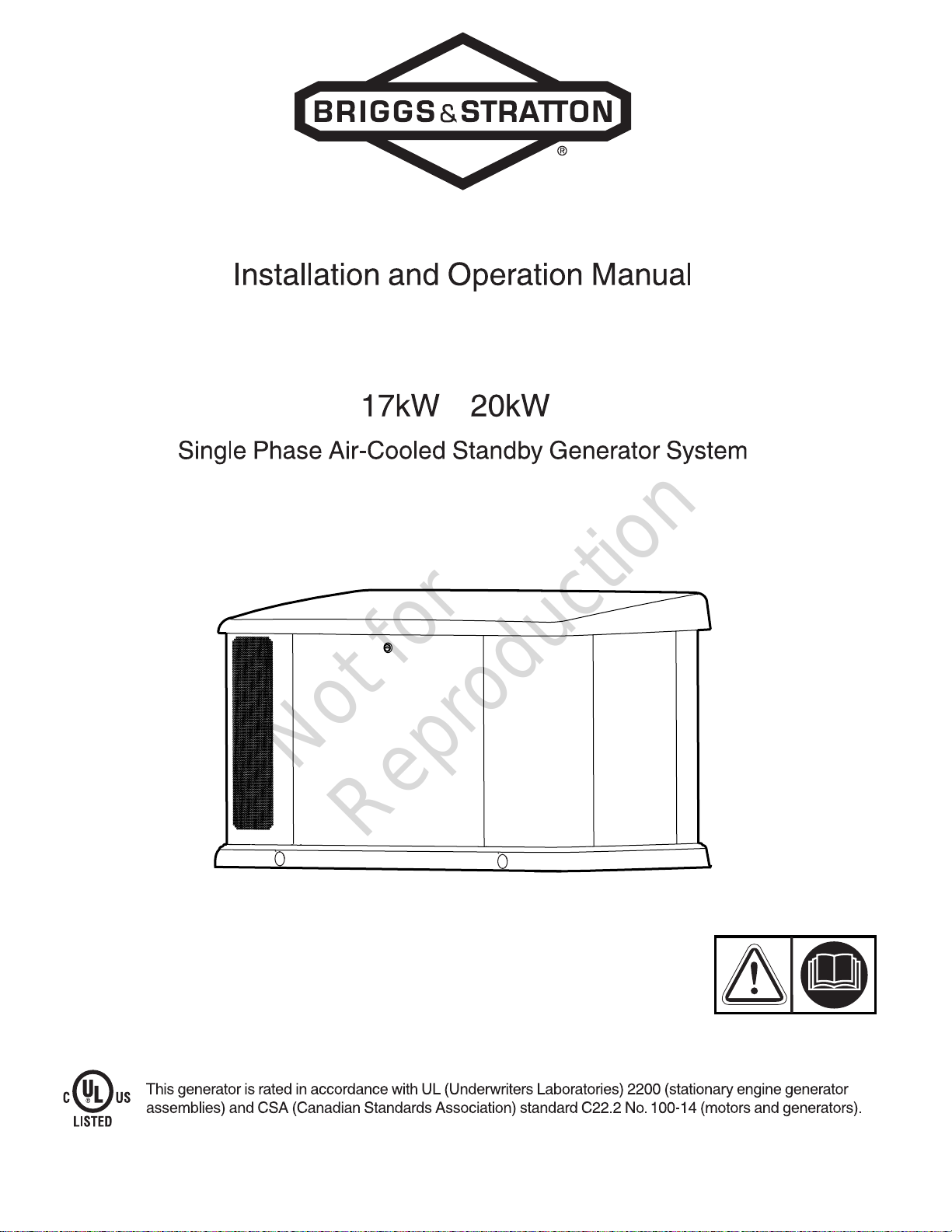
Not for
Reproduction
Copyright©Briggs & Stratton Corporation
Milwaukee, WI, USA. All Rights Reserved.
80081732
Revision B
Page 2

Table of Contents:
Not for
Reproduction
California Proposition 65..................................................... 3
Thank You..............................................................................3
Where to Find Us.................................................................. 3
For Future Reference........................................................... 3
Important Safety Instructions.............................................. 3
Safety Alert Symbol and Signal Words............................ 3
Safety Symbols and Meanings.........................................3
Safety Messages.............................................................. 4
FCC Part 15 Information To User.................................... 7
General Information..............................................................8
Equipment Description..................................................... 8
Installer Responsibilities................................................... 8
Owner Responsibilities..................................................... 8
Installation Factors to Consider........................................8
Delivery Inspection........................................................... 8
Shipment Contents........................................................... 8
Generator Placement............................................................9
Generator Location Considerations..................................9
Reduce the Risk of Carbon Monoxide Poisoning.............9
Reduce The Risk of Fire................................................ 11
Other General Location Guidelines................................ 13
Installation........................................................................... 14
Lifting the Generator...................................................... 14
Cold Weather Kit............................................................ 14
Anchoring and Wind Rating........................................... 14
Electrical and Fuel Inlet Locations................................. 15
Access Panels................................................................ 15
Fuel Installation Plan...................................................... 16
Electrical Field Connections........................................... 20
Final Installation Considerations.................................... 22
System Control Board.................................................... 23
Initial Start-Up (No Load)............................................... 24
Operation............................................................................. 26
Features and Controls - 17kW and 20kW
Generators......................................................................26
Important Owner's Considerations................................. 28
Automatic Operation Sequence..................................... 28
Setting the Exercise Timer............................................. 28
Maintenance.........................................................................30
Servicing the System..................................................... 30
Maintenance Schedule................................................... 30
Generator Maintenance..................................................30
Cleaning the Generator..................................................30
Engine Maintenance.......................................................31
Changing Engine Oil and Oil Filter.................................31
Adjust Valve Lash.......................................................... 32
Electronic Governor System...........................................33
Electronic Governing Check........................................... 33
Service the Spark Plugs.................................................34
Engine Air Cleaner......................................................... 34
Exhaust System Maintenance........................................ 35
Fuel System Maintenance.............................................. 35
Mixer/Throttle Control Device......................................... 35
Alarms (Service Code Detection System)...................... 35
Acknowledge and Reset the Alarms (Service Code
Detection System).......................................................... 35
Electrical System Maintenance...................................... 36
Troubleshooting.................................................................. 38
Troubleshooting.............................................................. 38
Diagrams and Schematics................................................. 40
Wiring Diagram and Schematic......................................40
Specifications...................................................................... 41
Generator Specifications: 17kW and 20KW................... 41
Engine Specifications..................................................... 41
2
Page 3
California Proposition 65
Not for
Reproduction
Model Revision: ____________________________
Serial Number: ____________________________
WARNING
This product can expose you to chemicals including used
engine oil, which is known to the State of California to
cause cancer, and carbon monoxide, which is known
to the State of California to cause birth defects or
other reproductive harm. For more information go
towww.P65Warnings.ca.gov.
Thank You
Thank you for purchasing this quality-built Briggs & Stratton®
generator. We are pleased that you have placed your
confidence in the Briggs & Stratton brand. When operated
and maintained according to the instructions in this manual,
your generator will provide many years of dependable
service.
This manual contains safety information to make you aware
of the hazards and risks associated with standby generators
and how to avoid them. This product is only for use as an
optional generator system which provides an alternate
source of electric power and to serve loads such as heating,
refrigeration systems, and communication systems that, when
stopped during any power outage, could cause discomfort or
inconvenience.
SAVE THESE INSTRUCTIONS -This manual contains
important instructions that must be obeyed during installation,
operation, and maintenance of the generator and batteries.
This generator system requires professional installation
before use.The installermust obeythe instructions
completely.
ENGINE:
Model Number: __________________________________
Serial Number: ___________________________________
Important Safety Instructions
Every effort has been made to make sure that the information
in this manual is accurate and current. However, we reserve
the right to change, or improve the product and this document
without notification.
The manufacturer cannot possibly anticipate every possible
circumstance that can involve a hazard. The warnings in
this manual, and the tags and decals affixed to the unit are,
therefore, not all-inclusive. If you use a procedure, work
method or operating technique that the manufacturer does
not recommend, you must satisfy yourself that it is safe for
you and others. You must also make sure that the procedure,
work method or operating technique that you choose does not
render the equipment unsafe.
Safety Alert Symbol and Signal Words
The safety alert symbol identifies safety information
about hazards that can result in personal injury. A signal
word (DANGER,WARNING, orCAUTION) is used with
the alert symbol to indicate the likelihood and the potential
severity of injury. In addition, a hazard symbol may be used
to represent the type of hazard.
Where to Find Us
You never have to look far to find support and service for
your equipment. There are many authorized service dealers
worldwide that provide quality service. You can also contact
Customer Service by phone at800-732-2989between 8:00
AM and 5:00 PM central time or click on Dealer Locator
at www.briggsandstratton.com, which provides a list of
authorized dealers.
For Future Reference
Please fill out the information below and keep with your
receipt. Have this information at hand if it becomes necessary
to contact your installer or authorized dealer regarding service
or repair of the unit.
Date of Purchase: ________________________________
Dealer / Retailer: _________________________________
Dealer's / Retailer'sPhone Number: __________________
GENERATOR:
Model Number: ____________________________
DANGERindicates a hazard which, if not
avoided,willresult in death or serious injury.
WARNINGindicates a hazard which, if not
avoided,couldresult in death or serious injury.
CAUTIONindicates a hazard which, if not
avoided,couldresult in minor or moderate injury.
NOTICEIndicates information considered important but not
hazard-related.
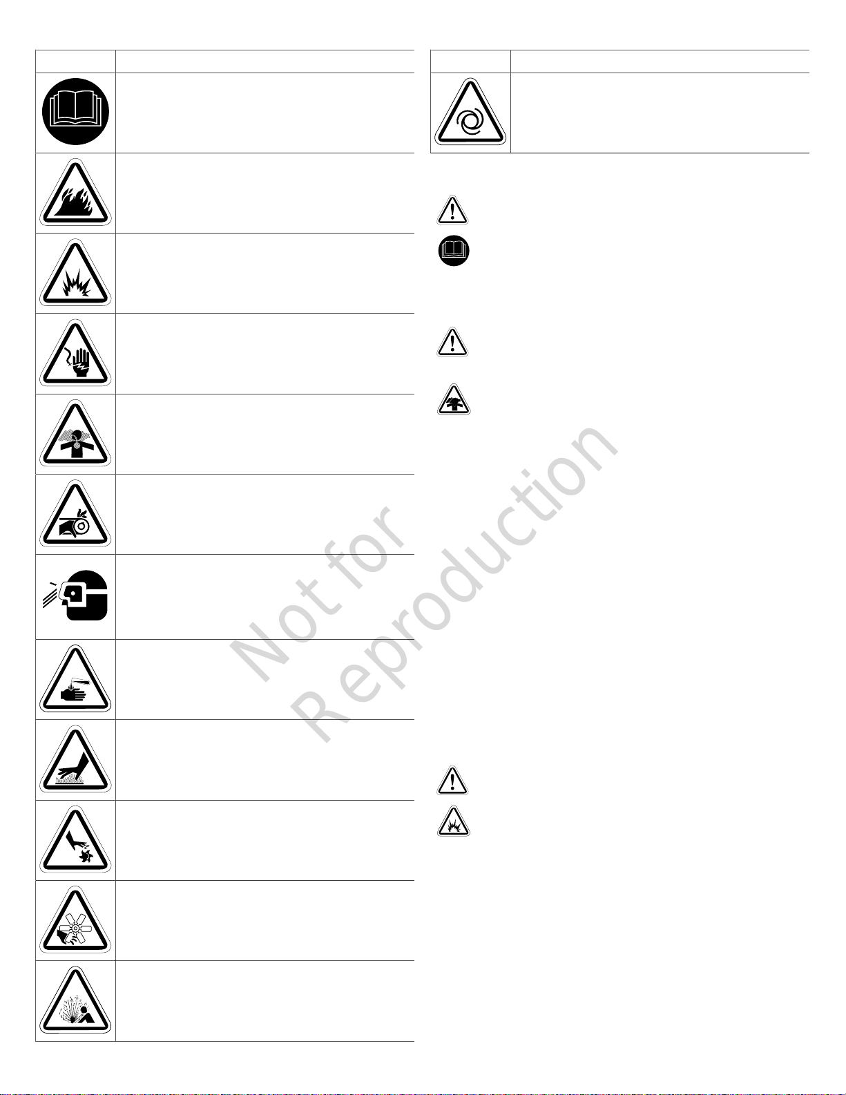
Safety Symbols and Meanings
Symbol Meaning
Safety alert symbol. Indicates a potential personal injury
hazard.
3
Page 4
Symbol Meaning
Not for
Reproduction
Read Manual. Failure to obey warnings, instructions,
installation manual, and operator’s manual could result in
death or serious injury.
Fire
Explosion
Electric Shock
Symbol Meaning
Auto Start
Safety Messages
WARNING
Failure to read and obey the operator’s manual, all
warnings, and operating instructions could result in death or
serious injury.
WARNING
Toxic Fumes
Moving Parts
Wear Eye Protection
Hazardous Chemical
Hot Surface
Rotating Parts
Engine exhaust contains carbon monoxide, a
poisonous gas that could kill you in minutes. You cannot
smell it, see it, or taste it. Even if you do not smell exhaust
fumes, you could still be exposed to carbon monoxide gas.
• Operate this product ONLY outdoors in an area that will
not accumulate deadly exhaust gas.
• Direct exhaust gas away from any windows, doors,
ventilation intakes, soffit vents, crawl spaces, open
garage doors or other openings that can allow exhaust
gas to enter inside or be drawn into a potentially
occupied building or structure.
• Carbon monoxide detector(s) MUST be installed and
maintained indoors according to the manufacturer’s
instructions/recommendations. Smoke alarms cannot
detect carbon monoxide gas.
• If you start to feel sick, dizzy, weak, or your carbon
monoxide alarm sounds while using this product, get to
fresh air right away. Call emergency services. You may
have carbon monoxide poisoning.
WARNING
Crush and Cut
Explosive Pressure
4
Storage batteries give off explosive hydrogen gas
during recharging. Slightest spark could ignite hydrogen
and cause explosion, resulting in death or serious injury.
• DO NOT dispose of battery in a fire. Recycle battery.
• DO NOT allow any open flame, spark, heat, or lit
cigarette during and for several minutes after charging a
battery.
Page 5
WARNING
Not for
Reproduction
WARNING
Battery electrolyte fluid contains acid and is extremely
caustic. Contact with battery contents could cause severe
chemical burns.
• DO NOT open or mutilate the battery
• Wear protective goggles, rubber apron, rubber boots
and rubber gloves.
• Immediately wash electrolyte from skin with water.
• If electrolyte contacts eyes, immediately flush with
water and seek medical attention.
• Spilled electrolyte is to be washed down with an acid
neutralizing agent.
WARNING
A battery presents a risk of high short circuit current.
• Remove watches, rings, or other metal objects.
• Use tools having insulated handles.
• Disconnect charging source prior to connecting or
disconnecting battery terminals.
• Do not lay tools or metal parts on top of batteries.
• Disconnect the negative (-) cable at the battery during
installation and maintenance.
WARNING
Hazardous Voltage -Installing low and high voltage
wire in same conduit could cause electric shock or burns,
resulting in death or serious injury.
• Do not run low and high voltage wire in the same
conduit unless the insulation rating on ALL wiring is
rated for 600V. See NFPA 70 for more information.
WARNING
Exhaust heat/gases could ignite combustibles or
structures resulting in death or serious injury.
• Exhaust outlet of enclosure must have at least 5 ft.
(1.5m) minimum clearance from any structure, shrubs,
trees, or any kind of vegetation.
• Enclosure must be at least 5 ft (1.5m) from windows,
doors, any wall opening, shrubs, or vegetation over 12
inches (30.5 cm) in height.
• Enclosure must have a minimum of 5 ft. (1.5 m)
overhead clearance from any structure, overhang, or
trees.
• DO NOT place enclosure under a deck or other type of
structure that may confine airflow.
• Smoke detector(s) MUST be installed and maintained
indoors according to the manufacturer’s instructions.
Carbon monoxide alarms cannot detect smoke.
• Do not place enclosure in a manner other than shown in
illustrations.
Failure to isolate generator from utility power could
result in death or serious injury to electric utility workers due
to backfeed of electrical energy.
• Use a listed transfer switch to connect to a building
electrical system.
WARNING
Generator and utility voltage could cause electrical
shock or burn resulting in death or serious injury.
• Installation must be performed by a licensed
professional.
• Disconnect all sources of electricity before installing or
servicing equipment.
• Ground system before applying power.
WARNING
Exhaust heat/gases could ignite combustibles
causing a fire, resulting in death or serious injury.
• Remove all combustible materials from in and around
the generator compartment.
WARNING
Gaseous vapors are extremely flammable and
explosive. Fire or explosion can cause severe burns or
death.
• Never start and run the engine with the air cleaner
assembly (if equipped) or the air filter (if equipped)
removed.
5
Page 6
WARNING
Not for
Reproduction
WARNING
With the battery connected, the generator may crank
and start without warning resulting in death or serious injury.
• Do not connect the negative (-) cable at the battery until
the installation is complete.
WARNING
With the battery connected, the generator may crank
and start without warning resulting in death or serious injury.
• Before servicing, stop the generator and disconnect the
negative (-) cable at the battery.
WARNING
Hazardous Voltage - Contact with power lines could
cause electric shock or burns, resulting in death or serious
injury.
• If lifting or hoisting equipment is used, DO NOT contact
any power lines.
• DO NOT lift or move generator without assistance.
Propane and Natural Gas are extremely flammable
and explosive, which could cause burns, fire or explosion
resulting in death or serious injury.
• LP gas is heavier than air and will settle in low areas.
• Natural gas is lighter than air and will collect in high
areas.
• The slightest spark could ignite these fuels and cause
an explosion.
• DO NOT light a cigarette or smoke.
WARNING
Propane and Natural Gas are extremely flammable
and explosive, which could cause burns, fire or explosion
resulting in death or serious injury.
• Inspect the fuel system periodically.
• NO leakage is permitted.
• DO NOT operate engine if smell of fuel is present.
WARNING
WARNING
Propane and Natural Gas are extremely flammable
and explosive, which could cause burns, fire or explosion
resulting in death or serious injury.
• Installation must be performed by a licensed
professional.
• Install the fuel supply system according to NFPA 37 and
other applicable fuel-gas codes.
• Before placing the generator into service, the fuel
system lines must be properly purged and leak tested.
• NO leakage is permitted.
• DO NOT operate engine if smell of fuel is present.
WARNING
Propane and Natural Gas are extremely flammable
and explosive, which could cause burns, fire or explosion
resulting in death or serious injury.
• The generator is equipped with an automatic safety
gasfuel shut-off valve.
• DO NOT operate the equipment if the fuel shut-off valve
is missing or inoperative.
Generatorand utilityvoltage could cause electrical
shock or burn resulting in death or serious injury.
• DO NOT allow unqualified persons to operate or
servicethis equipment.
WARNING
Unintentional sparking could cause fire or electric shock
resulting in death or serious injury.
WHEN ADJUSTING OR MAKING REPAIRS TO YOUR
GENERATOR
• Disconnect the spark plug wire from the spark plug and
place the wire where it cannot contact spark plug.
WHEN TESTING FOR ENGINE SPARK
• Use approved spark plug tester.
• DO NOT check for spark with spark plug removed.
6
Page 7

NOTICE Improper treatment of generator could damage it
Not for
Reproduction
and shorten its life.
• Use generator only for intended uses.
• If you have questions about intended use, contact your
authorized dealer.
• Operate generator only on level surfaces.
• Adequate, unobstructed flow of cooling and ventilating
air is critical to correct generator operation.
• The access panels/doors must be installed whenever
the unit is running.
• DO NOT expose generator to excessive moisture, dust,
dirt, or corrosive vapors.
• Remain alert at all times while working on this
equipment. Never work on the equipment when you are
physically or mentally fatigued.
• DO NOT insert any objects through cooling slots.
• DO NOT use the generator or any of its parts as a
step. Stepping on the unit could cause stress and
break parts. This may result in dangerous operating
conditions from leaking exhaust gases, fuel leakage, oil
leakage, etc.
• Shut off generator if:
• electrical output is lost.
• equipment sparks, smokes, or emits flames.
• unit vibrates excessively or makes unusual noises.
FCC Part 15 Information To User
Pursuant to part 15.21 of the FCC Rules, you are cautioned
that changes or modifications to the product not expressly
approved by Briggs & Strattoncould void your authority to
operate the product.
This device complies with part 15 of the FCC Rules.
Operation is subject to the following two conditions: (1) This
device may not cause harmful interference, and (2) this
device must accept any interference received, including
interference that may cause undesired operation.
This equipment has been tested and found to comply with
the limits for a Class B digital device, pursuant to part 15
of the FCC Rules. These limits are designed to provide
reasonable protection against harmful interference in a
residential installation. This equipment generates, uses and
can radiate radio frequency energy and, if not installed and
used in accordance with the instructions, may cause harmful
interference to radio communications. However, there is
no guarantee that interference will not occur in a particular
installation. If this equipment does cause harmful interference
to radio or television reception, which can be determined by
turning the equipment off and on, the user is encouraged to
try to correct the interference by one or more of the following
measures:
• Reorient or relocate the receiving antenna.
• Increase the separation between the equipment and
receiver.
• Connect the equipment into an outlet on a circuit different
from that to which the receiver is connected.
• Consult the dealer or an experienced radio/TV technician
for help.
7
Page 8

General Information
Not for
Reproduction
For most applications, this manual contains the information
necessary for the correct installation, operation, and
maintenance of the equipment. All efforts have been made to
make sure that the information in this manual is accurate and
current. We reserve the right to change the product and this
document without notification.
Equipment Description
NOTICE This product does NOT qualify for either an
emergency standby or legally required standby system as
defined by NFPA 70 (NEC).
• Emergency generator systems are intended to
automatically supply illumination, power, or both, to
designated areas and equipment in the event of failure
of the normal supply. Emergency systems can also
provide power for such functions as ventilation where
essential to maintain life, where current interruption of the
normal supply would produce serious life safety or health
hazards.
• Legally Required standby generator systems are
intended to automatically supply power to selected
loads in the event of failure of the normal source which
can create hazards or hamper rescue or fire-fighting
operations.
Installation Factors to Consider
The illustrations shown in this manual are for typical
circumstances. They are meant to familiarize you with the
installation options available for the generator.
Federal and local codes, appearance, noise levels, fuel types,
and distances are installation factors that must be considered.
Remember that, as the distance increases from the existing
electrical service and gaseous fuel supply, and the number
of bends in the fuel supply increases, compensations must
be made for piping and wiring materials. This is necessary
to comply with local codes and overcome electrical voltage
drops and gaseous fuel pressure drops.
Delivery Inspection
Avoid damage from dropping, bumping, or collision with the
shipping carton.
After removing the carton, carefully inspect the generator for
any damage that may have occurred during shipment.
If loss or damage is found at the time of delivery, have the
person(s) making the delivery notate the loss or damage on
the freight bill and affix his signature under the consignor’s
memo of loss or damage. If the loss or damage is notated
after delivery, separate the damaged materials and then
contact the carrier for claim procedures. Missing or damaged
parts are notwarranted.
Installer Responsibilities
• Read and obey the safety instructions.
• Install only aNRTL-approved transfer switch that is
compatible with the generator.
• Read and obey the instructions in this Installation and
Operation Manual.
• Installation must strictly comply with all applicable codes,
industry standards, laws, and regulations.
• Allow sufficient room on all sides of the generator for
maintenance and service.
• Discuss the generator placement with owner.
• Make sure that ALL manualsare given to the owner after
the installation has been completed.
Owner Responsibilities
• Read and obey the instructions in this Installation and
Operation Manual.
• Follow a regular schedule for maintaining and using the
generator, as specified in this manual.
• Carbon monoxide detector(s) MUST be installed and
maintained indoors according to the manufacturer’s
instructions and recommendations. Smoke alarms cannot
detect carbon monoxide gas.
• Smoke detector(s) MUST be installed and maintained
indoors according to the manufacturer’s instructions and
recommendations. Carbon monoxide alarms cannot
detect smoke.
Shipment Contents
The generator system is supplied with:
• Oil (5W30 Synthetic)
• Flexible fuel line
• Quick Operation Manual
• Product and emissions warranty booklet
• Two access keys
• Two 15 Amp ATO-type fuses
• Four lifting hole caps
• Touch up paint
Not included (You will need):
• Carbon monoxide detector(s)
• Smoke detector(s)
• Starting battery
• Connecting wire and conduit
• Fuel supply valves/plumbing
• Crane, lifting straps, chains or cables
• Two 60” (152cm) lengths of 3/4” (1.9cm) nominal
minimum Schedule 40 steel pipe (NOT conduit)
• Torque screwdriver, 5 to 50 inch-pound range
• Multi-meter
8
Page 9
Generator Placement
Not for
Reproduction
Before installing the generator, consult with the owner
and convey the following requirements, which must be
satisfied before the installation is complete. There are two
equally important safety concerns in regards to carbon
monoxide poisoning and fire. There are also several general
location guidelines that must be met before the installation is
considered complete.
WARNING
Engine exhaust contains carbon monoxide, a
poisonous gas that could kill you in minutes. You cannot
smell it, see it, or taste it. Even if you do not smell exhaust
fumes, you could still be exposed to carbon monoxide gas.
• Operate this product ONLY outdoors in an area that will
not accumulate deadly exhaust gas.
• Direct exhaust gas away from any windows, doors,
ventilation intakes, soffit vents, crawl spaces, open
garage doors or other openings that can allow exhaust
gas to enter inside or be drawn into a potentially
occupied building or structure.
• Carbon monoxide detector(s) MUST be installed and
maintained indoors according to the manufacturer’s
instructions/recommendations. Smoke alarms cannot
detect carbon monoxide gas.
• If you start to feel sick, dizzy, weak, or your carbon
monoxide alarm sounds while using this product, get to
fresh air right away. Call emergency services. You may
have carbon monoxide poisoning.
• DO NOT run this product inside homes, garages,
basements, crawlspaces, sheds, or other partiallyenclosed spaces even if using fans or opening doors and
windows for ventilation. Carbon monoxide can quickly
build up in these spaces and can linger for hours, even
after this product has shut off.
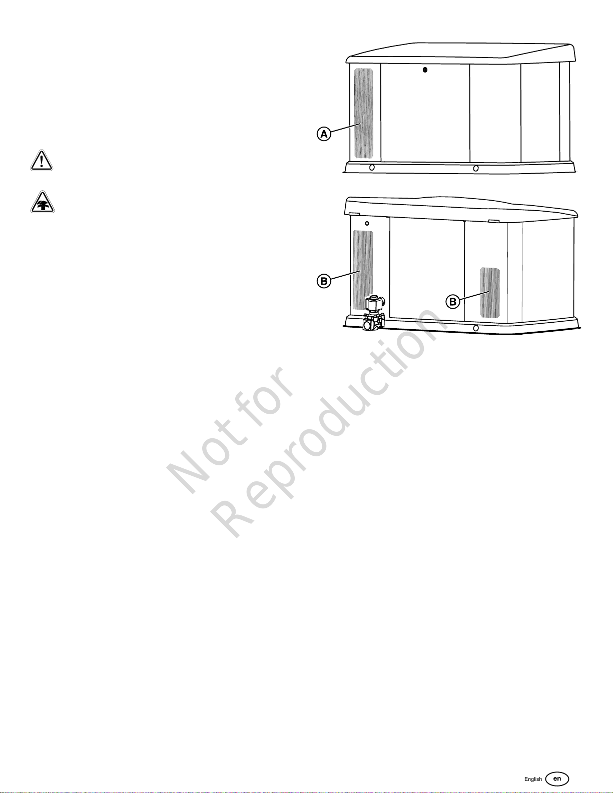
• ALWAYS place this product downwind and point the
engine exhaust (A) away from occupied spaces.
(A) Exhaust outlet side of enclosure.
(B)Air inlet side of enclosure.
Generator Location Considerations
The installation location of the generator has a direct effect
on:
1. The amount and size of the plumbing required to fuel the
generator.
2. The amount and size of the wiring required to control and
connect the generator.
3. The safety of the installation regarding exhaust gas and
carbon monoxide hazards, fire risks, proximity to other
utilities, and exposure to weather elements.
Specific location guidelines are discussed in the next
section. The owner and installer must consult one another
to determine how the site can affect installation costs and
compliance with local codes andstandards.
There are two critical safety concerns to be addressed carbon monoxide poisoning and the risk of fire, as follows:
Reduce the Risk of Carbon Monoxide Poisoning
The arrows in the figure below point to potential points of entry for Carbon Monoxide Gas.
9
Page 10
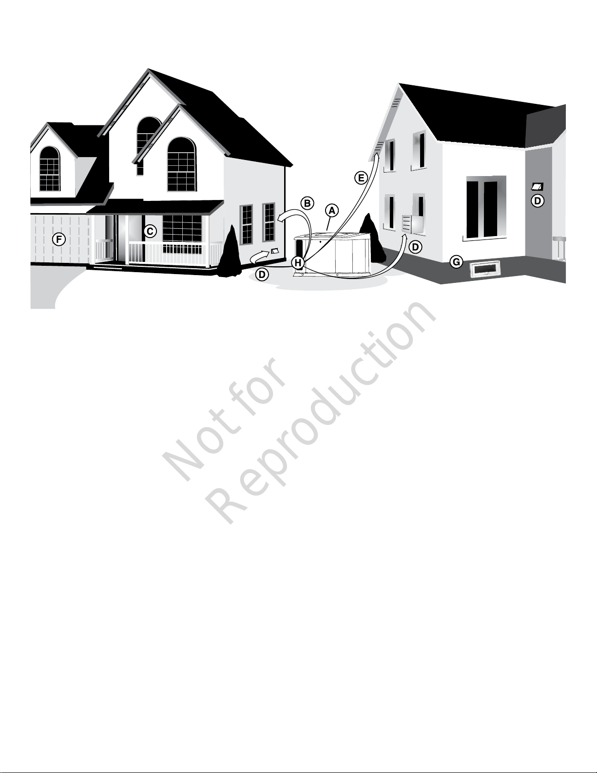
All fossil fuel burning equipment, such as standby generators (A), contains carbon monoxide (CO) gas in the engine exhaust
Not for
Reproduction
(H). CO gas is odorless, colorless and tasteless and is unlikely to be noticed until a person is overcome. CO gas can kill you
so it is required that the following is included as part of the installation.
• Install generator (A) outdoors in an area that will not accumulate deadly exhaust gas (H).
• DO NOT install the generator (A) where exhaust gas (H) can accumulate and enter inside or be drawn into a potentially
occupied building or structure.
• In many states it is required by law to have a Carbon Monoxide (CO) detector that works in your home. Carbon monoxide
detector(s) MUST be installed and maintained indoors according to the manufacturer’s instructions / recommendations. A
CO detector is an electronic device that detects hazardous levels of CO. When there is a buildup of CO, the detector will
alert the occupants with an alarm and by flashing a visual indicator light. Smoke alarms cannot detect CO gas.
• Your neighbor(s) home can be exposed to the engine exhaust (H) from your standby generator (A) and must be
considered when installing your standby generator.
• Make sure exhaust gas (H) is kept away from:
(B) Windows
(C) Doors
(D) Ventilation Intakes
(E) Soffit Vents
(F) Garage Doors
(G)Crawl spaces or other openings that can allow exhaust gas to enter inside or be drawninto a potentially occupied building
or structure.
10
Page 11
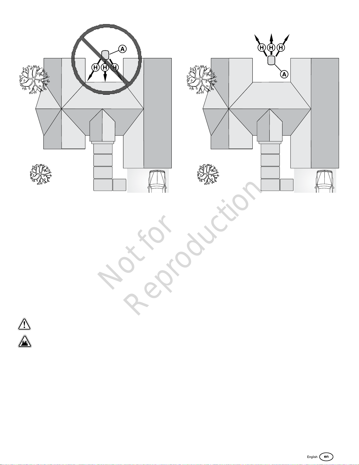
• Nearby structures may be exposed to the engine exhaust (H) from the generator (A) and must be considered when
Not for
Reproduction
installing the standby generator.
• Wind and air currents should be taken into consideration when positioning the generator (A). Place the generator in an
area where winds will carry the exhaust gas (H) away from any potentially occupied building or structure.
• DO NOT place the standby generator (A) in any area where leaves or debris can accumulate.
Reduce The Risk of Fire
Obey the installation requirements listed below. The figures below illustrate the minimum distances from structures and
vegetation to reduce the risk of fire.
The National Fire Protection Association (NFPA) standard NFPA 37 establishes criteria for minimizing the hazard of fire
during the installation and operation of stationary combustion engines. NFPA 37 limits the spacing of an enclosed generator
from openings in walls, structures and combustible materials outside the enclosure. The following generator placement
requirements are based on compliance to NFPA 37.
WARNING
Exhaust heat/gases could ignite combustibles or structures resulting in death or serious injury.
• Exhaust outlet of enclosure must have at least 5 ft. (1.5m) minimum clearance from any structure, shrubs, trees, or any
kind of vegetation.
• Enclosure must be at least 5 ft (1.5m) from windows, doors, any wall opening, shrubs, or vegetation over 12 inches (30.5
cm) in height.
• Enclosure must have a minimum of 5 ft. (1.5 m) overhead clearance from any structure, overhang, or trees.
• DO NOT place enclosure under a deck or other type of structure that may confine airflow.
• Smoke detector(s) MUST be installed and maintained indoors according to the manufacturer’s instructions. Carbon
monoxide alarms cannot detect smoke.
• Do not place enclosure in a manner other than shown in illustrations.
11
Page 12
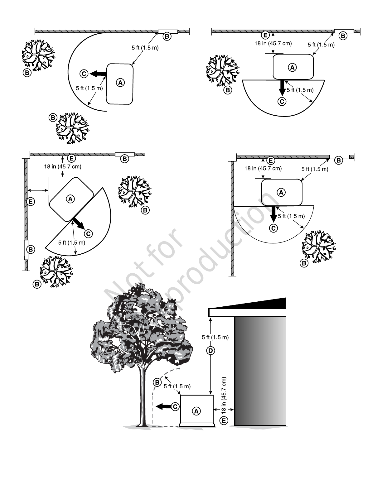
Legend for Generator Locations to reduce the risk of fire:
Not for
Reproduction
(A) Standby Generator
12
Page 13

(B)Standby enclosure must be at least 5 ft (1.5 m) from windows, doors, any wall opening, shrubs or vegetation over 12
Not for
Reproduction
inches (30.5 cm) in height.
(C)Exhaust outlet of standby enclosure must have at least 5 ft (1.5 m) minimum clearance from any structure, shrubs, trees
or any kind of vegetation.
(D)Standby enclosure must have a minimum of 5 feet (1.5 m) overhead clearance from any structure, overhang or trees.
(E)Standby enclosure must have a minimum of 18 inches (45.7 cm) clearance from any structures with or without a fire
rating.
Other General Location Guidelines
• Place the standby generator in a prepared location that is
flat and has provisions for water drainage.
• Install the standby generator in a location where sump
pump discharge, rain gutter down spouts, roof run-off,
landscape irrigation, or water sprinklers will not flood the
unit or spray the enclosure and enter any air inlet or outlet
openings.
• Install the standby generator where it will not affect or
obstruct any services (including covered, concealed and
underground), such as telephone, electric, fuel (natural
gas / LPG vapor), irrigation, air conditioning, cable, septic,
sewer, well and so forth.
• Install the standby generator where leaves, grass, snow,
etc will not obstruct air inlet and outlet openings. If
prevailing winds will cause blowing or drifting, you may
need to construct a windbreak to protect the unit.
13
Page 14
Installation
Not for
Reproduction
This product is only for use as an optional generator system
which provides an alternate source of electric power
and to serve loads such as heating, refrigeration, and
communication systems that, when stopped during any power
outage, can cause discomfort or inconvenience.
Every effort has been made to make sure that the information
in this manual is accurate and current. However, we reserve
the right to change, alter, or otherwise improve the product
and this document at any time without prior notice.
Only current licensed electrical and plumbing professionals
can attempt generator system installations. Installations must
strictly comply with all applicable codes, industry standards,
laws and regulations.
Lifting the Generator
WARNING
Hazardous Voltage - Contact with power lines could
cause electric shock or burns, resulting in death or serious
injury.
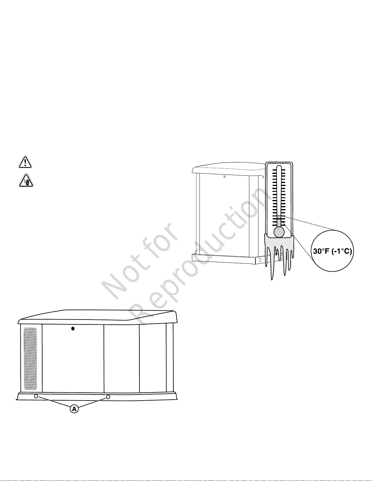
Cold Weather Kit, Part No. 6578 (Fortress models) includes:
• Battery warmer
• Battery stand
Cold Weather Kit, Part No. 6567 (Briggs & Stratton models)
includes:
• Oil warmer
• Battery warmer
• Battery stand
• Wire harness
These items are available at your local service dealer.
If you need more information, please
call800-732-2989between 8:00 AM and 5:00 PM CT.
• If lifting or hoisting equipment is used, DO NOT contact
any power lines.
• DO NOT lift or move generator without assistance.
Proper tools, equipment, and qualified personnel must be
used in all phases of handling and moving the generator. The
approximate weight of the generator is listed in theGenerator
Specificationssection.
Use the lifting holes (A) in the base of the generator to lift
the generator onto the concrete pad. Lift the generator in
accordance with OSHA or local lifting regulations. Retouch
any chipped paint with the supplied touch-up paint.
Anchoring and Wind Rating
Concrete Anchoring of Unit to Poured or
Existing Slab
To achieve the listed wind rating, the generator must be
installed in strict compliance with this installation manual.
The product components must be of the material specified
and all screws must be installed in accordance with the
applicable provisions and the anchor manufacturer’s
published installation instructions.
Cold Weather Kit
If the generator operates in temperatures below 30°F (-1°C),
it is HIGHLY RECOMMENDED that a Cold Weather Kit be
installed.
14
The concrete slab/pad must meet the requirements below
and the generator must be anchored with the anchors
ofAnchor Types1 or 2.
Anchor Types
1. Qty (4) 3/8” SS ITW RED HEAD LDT, Anchor embedded
2 ½” (63.5mm) in 3000 psi concrete. 3” (76.2mm) from
the edge minimum, 6” (152.4mm) spacing minimum.
Page 15
2. Qty (4) 3/8” SS Powers/Dewalt Power Stud +SD2
Not for
Reproduction
Anchor embedded 2 ½” (63.5mm) in 3000 psi concrete.
3” (76.2mm) from the edge minimum, 6” (152.4mm)
spacing minimum.
140 to 175 Poured 38in
(965.2mm)
These items are available at your local service dealer.
55in
(1397mm)
5in
(127mm)
3000 PSI
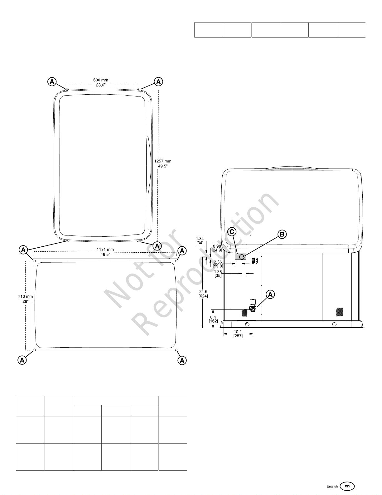
There are four 7/16” hole locations (A) in the base of the
generator in which to anchor the unit.
NOTICE Unless mandated by local or state codes, or
required to achieve wind rating, a concrete slab/pad is not
required
Electrical and Fuel Inlet Locations
The 3/4 inch N.P.T. fuel inlet connector (A) and electrical inlet
locations (B) are shown below.
A ½ inch knock-out is provided for the electrical inlet. This
inlet may be enlarged or supplemented to accommodate a
maximum conduit size of 1-½ inches. Make sure that the
installed conduit(s) enter the unit in zone (C) as shown in the
drawing below so that they properly enter the electrical box
and do not interfere with the fully opened roof.
Concrete Slab/Pad Types
RATING
MPH
Up to 140 Pre-cast
140 to 175 Pre-cast
PAD
MODEL
Pad
(contact
dealer)
Pad
(contact
dealer)
37in
(939.8mm)
37in
(939.8mm)
PAD DIMENSIONSWIND
Width Length Thickness
54.4in
(1381.8mm)
54.4in
(1381.8mm)
3in
(76.2mm)
4in
(101.6mm)
CONCRETE
SPEC
3000 PSI
3000 PSI
Access Panels
The generator enclosure has several access panels, as
shown.
The access panels and the components located behind them
are listed below:
(A) Roof (Control Panel, air filter, oil dipstick, and circuit
breaker)
(C) Rear Access Panel (fuel regulator, fuel selector, and
engine starter)
(D) Control Panel Cover (field wiring and control wires)
(F) Battery Panel (battery and generator data label)
(H) Front Access Panel (oil drain and oil filter)
15
Page 16
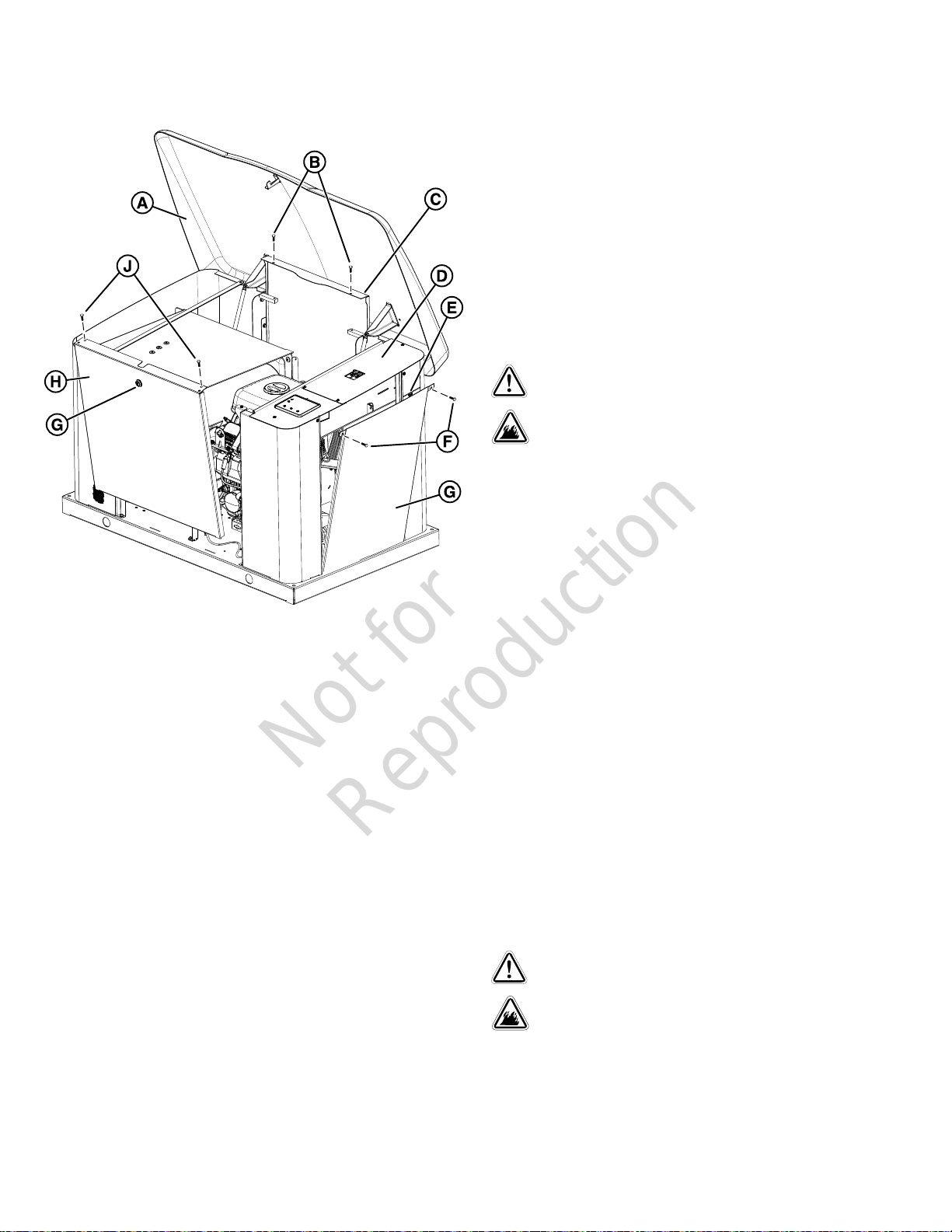
Each generator is shipped with a set of identical keys
Not for
Reproduction
fastened to the fuel solenoid.
Open the roof (A):
1. Insert key into lock (G) of front panel (H). Gently push
down on the roof above the lock to assist in turning the
key. Turn the key one quarter turn clockwise.
2. Lift the roof (A) to the open position.
Battery panel removal (G):
1. Make sure that the roof is in the open position.
2. Remove the two bolts (F) that secure the panel (G) to the
unit.
3. Lift up on the panel (G) and remove it.
Note:Fuse holder (E) is located behind the battery panel (G).
Attach battery panel (G):
1. Put the panel (G) in the unit.
2. Attach the panel (G) with the two bolts (F).
Fuel Installation Plan
WARNING
Propane and Natural Gas are extremely flammable
and explosive, which could cause burns, fire or explosion
resulting in death or serious injury.
• Installation must be performed by a licensed
professional.
• Install the fuel supply system according to NFPA 37 and
other applicable fuel-gas codes.
• Before placing the generator into service, the fuel
system lines must be properly purged and leak tested.
• NO leakage is permitted.
• DO NOT operate engine if smell of fuel is present.
NOTICE The supplied flexible fuel line is not to be
installed underground or in contact with the ground.
Front panel removal (H):
1. Remove the two bolts (J) that secure the panel (H) to the
unit.
2. Lift the panel (H) to remove from unit.
Attach the front panel (H):
1. Put the panel (H) in the unit.
2. Attach the panel (H) with the two bolts (J).
Rear panel removal (C):
1. Make sure that the roof (A) is in the open position.
2. Remove the two bolts (B) that secure the panel (C) to the
unit.
3. Lift the panel (C) to remove it from the unit.
Attach the rear panel (C):
1. Slide the panel (C) into place on the unit.
2. Attach the panel with the two bolts (B).
• The entire flexible fuel line must be visible for periodic
inspection and must not be concealed within nor contact
nor run through any wall, floor, or partition.
The information below is provided to assist gaseous fuel
system technicians in planning installations. In no way
should this information be interpreted to conflict with
applicable fuel gas codes. Consult with your local fuel
supplier or Fire Marshall if questions or problems arise.
WARNING
Propane and Natural Gas are extremely flammable
and explosive, which could cause burns, fire or explosion
resulting in death or serious injury.
• The generator is equipped with an automatic safety
gasfuel shut-off valve.
• DO NOT operate the equipment if the fuel shut-off valve
is missing or inoperative.
16
Page 17
WARNING
Not for
Reproduction
Propane and Natural Gas are extremely flammable
and explosive, which could cause burns, fire or explosion
resulting in death or serious injury.
• LP gas is heavier than air and will settle in low areas.
• Natural gas is lighter than air and will collect in high
areas.
• The slightest spark could ignite these fuels and cause
an explosion.
• DO NOT light a cigarette or smoke.
TO THE INSTALLER:Consult with the generator owner(s)
and convey any technical considerations that can affect their
installation plans before applying these general guidelines.
The following general rules apply to gaseous fuel system
piping:
• The piping material must conform to federal and local
codes, be rigidly mounted, and be protected against
vibration.
• Piping should be protected from physical damage,
especially where it passes through flower beds, shrub
beds, and other cultivated areas where damage can
occur.
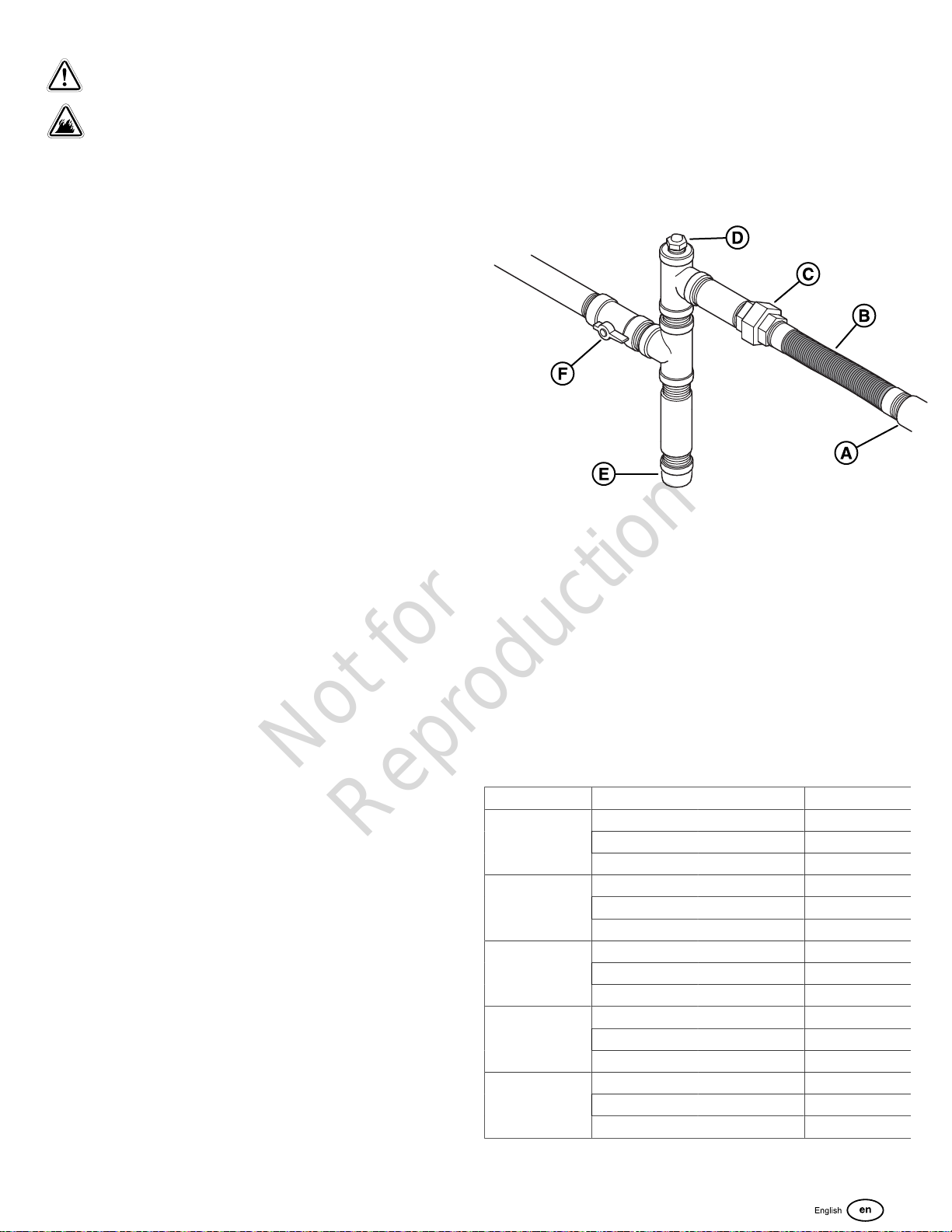
• Install the provided flexible fuel line (B) between the
generator fuel inlet port (A) and the rigid piping to
prevent thermal expansion and contraction from causing
excessive stress on the piping material.
• A union (C) or a flanged connection must be provided
downstream to permit removal.
• A manometer test port (D) should be installed for
vapor fuels. Use the port to install a manometer and
check if the engine receives the correct fuel pressure
for operation. A digital manometer (P/N 19495) or an
analogmanometeris available at your service center for
vapor fuels only. When the initial test runs are completed,
the manometer is removed and the port is plugged.
• For vapor fuels only: Where the formation of hydrates or
ice is known to occur, piping should be protected against
freezing. The termination of hard piping must include
a sediment trap (E) where condensate is not likely to
freeze.
• A minimum of one accessible, approved manual shutoff
valve (F) shall be installed in the fuel supply line within 6
ft (180 cm) of the generator.
• You must install a manual fuel shut-off valve in the interior
of the building.
• Where local conditions include earthquake, tornado,
unstable ground, or flood hazards, special consideration
shall be given to increase strength and flexibility of piping
supports and connections.
• Piping must be of the correct size to maintain the
required supply pressures and volume flow under
varying generator load conditions with all gas appliances
connected to the fuel system turned on andoperating.
• Use a pipe sealant or joint compound approved for
use with NG/LP on all threaded fittings to reduce the
possibility of leakage.
NOTICE Keep thread sealant out of the gas piping to
prevent component part damage.
• Installed piping must be properly purged and leak tested,
in accordance with applicable codes andstandards.
(A) Generator Fuel Inlet
(B)Flexible Fuel Line
(C)Union Fitting
(D)Manometer Test Port
(E)Sediment Trap
(F)Manual Shut-off Valve
Fuel Consumption
Estimated fuel supply requirements at half and full load for
natural gas and LP vapor fuels are shown below.
LP Vapor (Propane)
20 kW 17 kW
Full Load
3/4 Load
1/2 Load
1/4 Load
Exercise
Natural Gas
Cu Ft/Hr 135 118
Gal/Hr (liquid) 3.75 3.28
BTU/Hr 337500 295000
Cu Ft/Hr 109 99
Gal/Hr (liquid) 3.03 2.75
BTU/Hr 272500 247500
Cu Ft/Hr 83 74
Gal/Hr (liquid) 2.31 2.06
BTU/Hr 207500 185000
Cu Ft/Hr 56 54
Gal/Hr (liquid) 1.56 1.5
BTU/Hr 140000 135000
Cu Ft/Hr 40 40
Gal/Hr (liquid) 1.11 1.11
BTU/Hr 100000 100000
17
Page 18

20 kW
Not for
Reproduction
(18 kW)
Cu Ft/Hr 260 248Full Load
BTU/Hr 260000 248000
Cu Ft/Hr 240 2183/4 Load
BTU/Hr 240000 218000
Cu Ft/Hr 187 1701/2 Load
BTU/Hr 187000 170000
Cu Ft/Hr 135 1281/4 Load
BTU/Hr 135000 128000
Cu Ft/Hr 99 99Exercise
BTU/Hr 99000 99000
17 kW
15.3 kW
For Natural Gas fuel pressure levels of 3.5 - 5" W.C., replace
the regulator assembly with service kit 6331-00 (available at
your local service dealer).
Power Loss
Air density is less at high altitudes, resulting in less available
engine power. Engine power will decrease by 3.5% for each
1,000 feet (300 m) above sea level and by 1% for each
10° F (5.6°C) above 77°F (25°C). Generators located in
these conditions must have their transfer switch adjusted
appropriately for this power decrease. See your Automatic
Transfer Switch manual on how to adjust for the power
decrease.
Recommended
Energy Content of
FuelHeating Value:
Heating Value:
BTU per gallon (gross**)
Cubic feet (gas)
LP Vapor Natural Gas
91,547
2,500
1,000
Fuel Type
An important consideration affecting the entire installation
is the type of fuel used by your generator. The system was
factory tested and adjusted using natural gas, but can be
converted to use LP vapor. For correct engine function,
factors that are inherent to each of these fuels, like your
location and the duration of possible utility interruptions, are
important considerations in the following fuel guidelines:
• Use clean, dry fuel that is free of moisture or
any particulate material. Using fuels outside the
recommendation values that follow can cause
performance problems.
• In engines set up to run on propane (LP), commercial
grade HD5 propane with a minimum fuel energy of 2500
BTUs/ft3 with maximum propylene content of 5% and
butane and heavier gas content of 2.5% and minimum
propane content of 90% is required.
Natural gas rating will depend on specific fuel, but typical
derates are between 10 and20% of the LP gas rating.
Natural gas or LP engines are certified to operate on natural
or liquid propane gas. The emissions control system for this
engine is EM (Engine Modifications).
The Gaseous Fuel System
Fuel Pipe Sizing
NFPA 54 and 58 are common resources. The installer must
consider the specific gravity of gas, compensate for a nominal
amount of restriction from bends and fittings, and refer to
federal and local codes for guidance.
Fuel Conversion
The engine of your home generator system is factory
Calibrated and set to operate on natural gas (NG). It may also
be operated on liquefied petroleum (LP) vapor.
NOTICE Units are set to NG at the factory.
To convert to either fuel, follow these steps:
1. Put the key into the lock of the front panel. Lightly push
down on the roof above the lock, and then turn the key
one quarter turn clockwise.
2. Lift the roof to the open position.
3. Push the control panel OFF button.
4. Remove the battery panel.
5. Remove the 15 Amp fuse.
6. Remove utility power to generator to de-energize the
battery charger.
7. Disconnect the negative (-) cable at the battery.
8. Remove the rear panel.
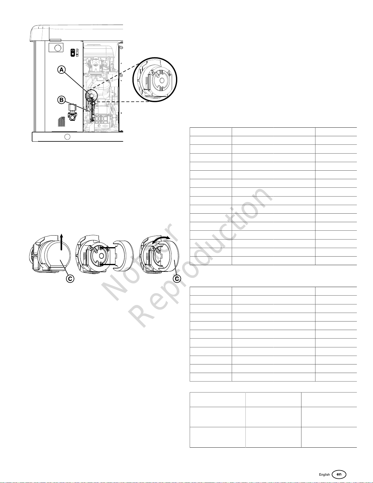
9. Find the fuel selector switch (A) on top of the fuel
regulator (B).
Fuel Pressure
Both LP vapor and natural gas fuel supply pressure at the
generator’s fuel inlet port and must be between the following
levels at full load with all gas appliances turned on and in
operation.
• NG is 3.5-7” W.C.
• LP is 11-14” W.C.
Make sure that all gas line shutoff valves are OPEN and
that adequate fuel pressure is available whenever automatic
operation is desired.
18
Page 19
10. Set Fuel Selector:
Not for
Reproduction
A. Remove cap (C) from the Fuel Select Valve by sliding
it upward.
Note:If this is the first installation of this generator,
thecapwill be found in the parts bag.
B. LP or NG is selected by using the cap (C) as a tool to
rotate the indicator to the LP or NG mark (the image
below shows the FSV set to LP fuel).
C. Install the cap (C) after fuel selection is complete.
20. To Save the new fuel setting, press and hold the STOP/
CONFIG button until “Saving Settings…” is displayed.
21. For Additional information on the operation of the
generator controller please refer to the "Operation
Instructions GC1031 GENSET Controller Manual,"
PN:80086364.
22. Close the roof.
23. Restore utility power to generator.
24. Push the control board AUTO button.
Fuel Consumption
LP Vapor (Propane)
20kW 17kW
Full Load Cu Ft/Hr 135 118
Gal/Hr (liquid) 3.75 3.28
BTU/Hr 337,500 295,000
3/4 Load Cu Ft/Hr 109 99
Gal/Hr (liquid) 3.03 2.75
BTU/Hr 272,500 247,500
1/2 Load Cu Ft/Hr 83 74
Gal/Hr (liquid) 2.31 2.06
BTU/Hr 207,500 185,000
1/4 Load Cu Ft/Hr 56 54
Gal/Hr (liquid) 1.56 1.5
BTU/Hr 140,000 135,000
No Load Cu Ft/Hr 40 40
Gal/Hr (liquid) 1.11 1.11
BTU/Hr 100,000 100,000
11. Once the fuel selection is complete, apply a drop of
cyanoacrylate (super) glue on the Fuel Select Cap.
12. Connect the negative (-) cable at the battery.
13. Install the rear panel.
14. Install 15-amp fuse.
15. Install the battery panel.
16. Push and hold the CONFIG button to access the
configuration menu.
17. Push SELECT to edit the items in the configuration menu.
18. To setup the generators control board for LP fuel you will
need to enter the Configuration Menu by using the Dealer
Password, which is available on the Power Portal.
19. Navigate to “SELECT PROFILE” and press select on the
correct profile for the generator. For example “20KW_LP”
for operating a 20kW unit running on LPfuel.
Note:Selecting a profile that is not intended for the generator
can cause the generator to run erratically and could result in
damage.
Natural Gas
20kW 17kW
Full Load Cu Ft/Hr 260 248
BTU/Hr 260,000 248,000
3/4 Load Cu Ft/Hr 240 218
BTU/Hr 240,000 218,000
1/2 Load Cu Ft/Hr 187 170
BTU/Hr 187,000 170,000
1/4 Load Cu Ft/Hr 135 128
BTU/Hr 135,000 128,000
No Load Cu Ft/Hr 99 99
BTU/Hr 99,000 99,000
Recommended Energy
Content of Fuel:
Heating Value:
BTU per gallon liquid
(gross*)
Heating Value:
BTU per Cubic feet
(vapor)
Natural Gas Propane (LP Vapor)
N/A 91,547
1,000 2,500
19
Page 20
Electrical Field Connections
Not for
Reproduction
WARNING
Generator and utility voltage could cause electrical shock or burn resulting in death or serious injury.
• Installation must be performed by a licensed professional.
• Disconnect all sources of electricity before installing or servicing equipment.
• Ground system before applying power.
WARNING
Hazardous Voltage -Installing low and high voltage wire in same conduit could cause electric shock or burns,
resulting in death or serious injury.
• Do not run low and high voltage wire in the same conduit unless the insulation rating on ALL wiring is rated for 600V.
See NFPA 70 for more information.
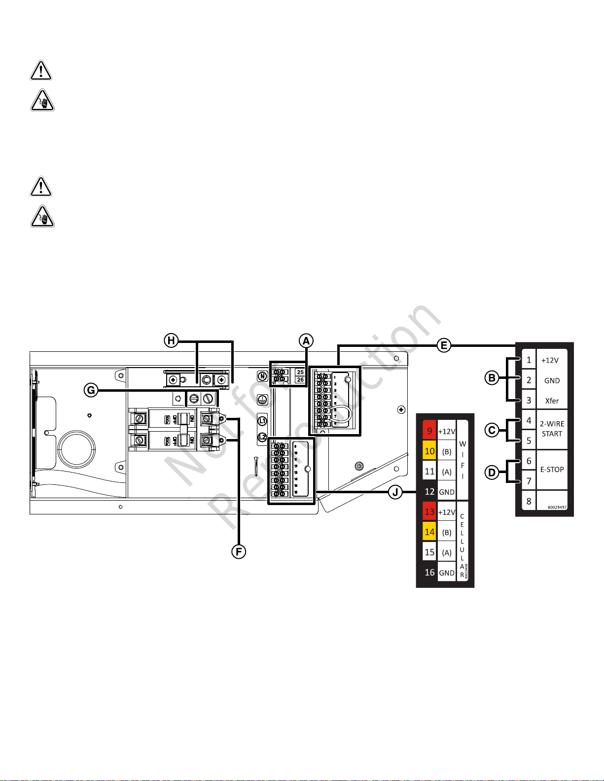
Low Voltage connections are made via a field connections terminal block (E) in main electrical area. Compare this illustration
with your generator to familiarize yourself with the location of these connections.
Legend for System Connector Location
(A)Two Pin Terminal Block — Used to connect utility 240 VAC from fuse block in ATS to the control board. Connect only one
wire per terminal. Use #14 [2.5mm2] AWG minimum 300 volt wire.
(B) Transfer Switch Connection — Controls Briggs & Stratton®transfer switch.
(C) 2-wire start—Used for optional remote start contact.
(D) E-Stop—For use with with optional external E-stop.
(E) Field Connections Terminal Block—Reference the table that follows.
(F)Power Connection (L1 and L2) — Power connection to transfer switch.
(G)Ground Connection — Connect to transfer switch ground wire.
20
Page 21
(H)Neutral Connection — Connect to transfer switch neutral wire.
Not for
Reproduction
(J) Communications Terminal Block— Reference the table that follows.
Pin Number Description Wire type Connect To Notes
1 12VDC 18AWG[1mm2] conductors,
300V minimum, 90°C Cu wire.
2 GND 18AWG[1mm2] conductors,
300V minimum, 90°C Cu wire.
3 Transfer Signal 18AWG[1mm2] conductors,
300V minimum, 90°C Cu wire.
4 2Wire-Start 18AWG[1mm2] conductors,
300V minimum, 90°C Cu wire.
5 2Wire-Start 18AWG[1mm2] conductors,
300V minimum, 90°C Cu wire.
6 E-Stop 18AWG[1mm2] conductors,
300V minimum, 90°C Cu wire.
7 E-Stop 18AWG[1mm2] conductors,
300V minimum, 90°C Cu wire.
8 Not Used
9 12VDC 18AWG[1mm2] conductors,
300V minimum, 90°C Cu wire.
10 (B) 18AWG[1mm2] conductors,
300V minimum, 90°C Cu wire.
11 (A) 18AWG[1mm2] conductors,
300V minimum, 90°C Cu wire.
12 GND 18AWG[1mm2] conductors,
300V minimum, 90°C Cu wire.
13 12VDC 18AWG[1mm2] conductors,
300V minimum, 90°C Cu wire.
14 (B) 18AWG[1mm2] conductors,
300V minimum, 90°C Cu wire.
15 (A) 18AWG[1mm2] conductors,
300V minimum, 90°C Cu wire.
16 GND 18AWG[1mm2] conductors,
300V minimum, 90°C Cu wire.
25 Utility 14AWG [2.5mm2] 300V
minimum, 90°C Cu Wire
26 Utility 14AWG [2.5mm2] 300V
minimum, 90°C Cu Wire
Transfer switch basic
controller J7-8 12VDC
Transfer switch basic
controller J7-7 GND
Transfer switch basic
controller J7-4 T/R
Refer to Transfer switch
manual to verify if this function
is available.
E-Stop Switch
E-Stop Switch
Refer to the Amplify Gateway
Manual.
Refer to the InfoHub™
Premium Manual.
Transfer switch Utility
Transfer switch Utility
Transfer switch Transfer
Signal (only works with basic
Transfer Switch Controller).
Contact Close for
Genset Start.(Only for
transferswitch that provides
this option)
Mains monitoring must be
disabled in the controller.
Contact Open to Shutdown
Genset
Comm to WIFI module
Twisted pair #1: +12V and
GND
Twisted pair #2: (A) and (B)
Comm to Cellular module
Twisted pair #1: +12V and
GND
Twisted pair #2: (A) and (B)
Voltage Sensing for Genset
Start. Use either this signal or
2-wire start signal for Genset
Start Signal.
• For power output connection (L1, L2, Neutral (N), and Ground), refer to the National Electric and local codes.
• For communication wires use #18 AWG [1mm2] twisted pair conductors, no greater than 500 ft in length, 300 volt wire.
• When connecting to the terminal block, fasten only one wire to each connector screw.
• Torque terminal block screws to 4.4 in-lb [0.49 Newton meter].
• Torque circuit breaker connections to 45 in-lb [5 Newton meter].
Generator ACSystem Connection
A single-phase, three-wire AC connection system is used
in the generator. The stator assembly consists of a pair
NOTICE Generator must be used with only an UL
approved transfer switch that is compatible with the
generator.
of stationary windings with two leads brought out of each
winding. The junction of leads 22 and 33 forms the neutral
lead, as shown schematically and as a wiring diagram.
NOTICE Neutral is not bonded to ground at generator.
21
Page 22
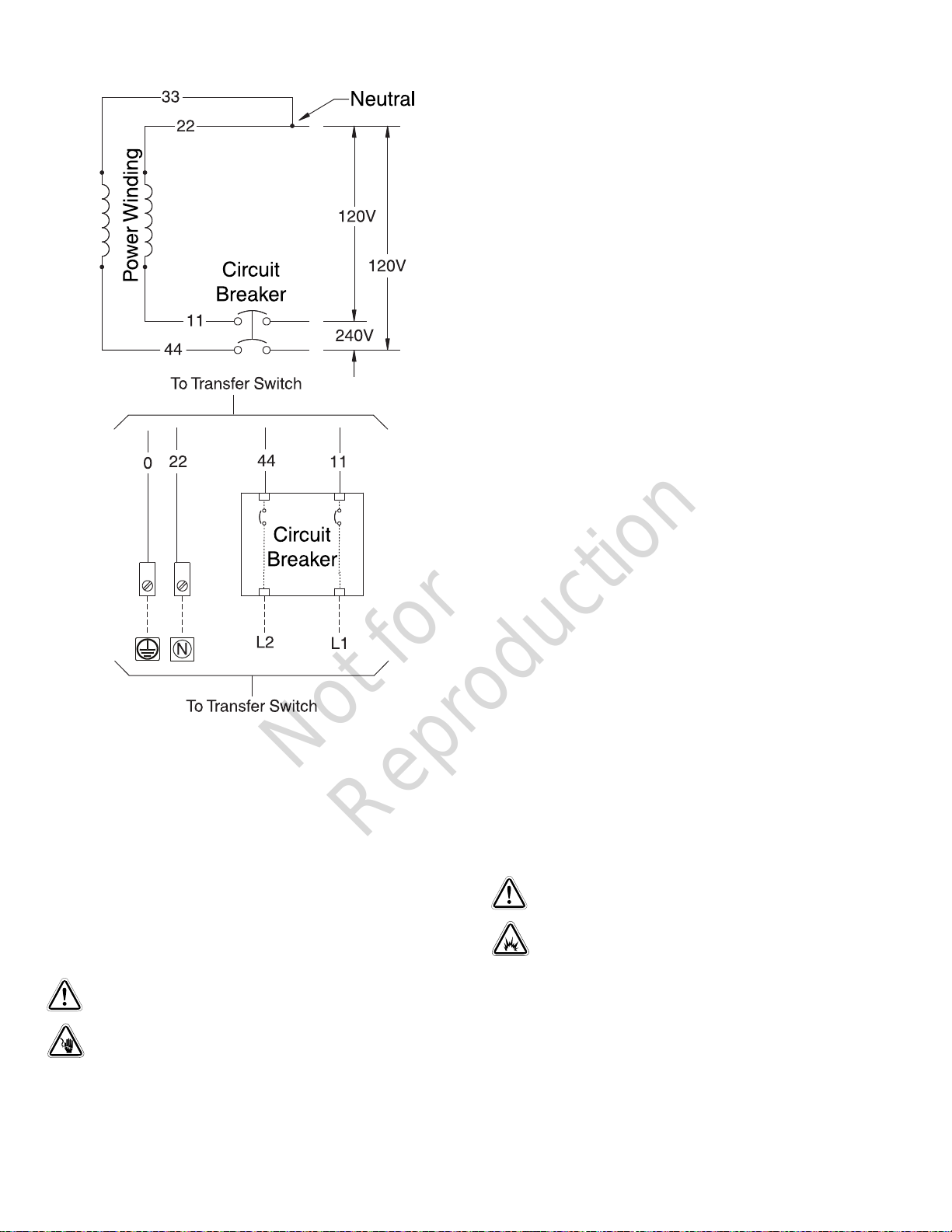
240V Utility leads must be routed in conduit. The 240V Utility
Not for
Reproduction
leads deliver power to the generator’s circuit board, optional
battery warmer and optional oil warmer. This power also
charges the battery. In AUTO Mode, when the power on
these leads is lost, the generator will start. Using the installersupplied minimum 300V, 14 [2.5 mm2] AWG wire, connect
each control circuit terminal in the generator (25 and 26) to
the fuse block in the automatic transfer switch.
Generator Power Connection
Using the installer supplied minimum 300V wires and the
table located in theElectrical Field Connectionssection,
connect generator power output L1, L2, neutral (N), and
ground to the corresponding L1, L2, neutral (N) and ground in
the transfer switch.
NOTICE Refer to the National Electric Code for correct
electrical field connections and wire size calculations.
Final Installation Considerations
Engine Oil
NOTICE Any attempt to crank or start the engine before it
has been correctly filled with the recommended oil will result
in equipment failure and service codes.
Grounding the Generator
Unless mandated by local code, additional chassis grounding
to earth at the generator is not required. Any grounding
at generator must use metal piercing lock washers (or
equal), listed terminals installed per terminal supplier’s
instructions, and comply with national electrical codes and
local requirements.
Power Connections from the Generator to the
Transfer Switch
WARNING
Failure to isolate generator from utility power could
result in death or serious injury to electric utility workers due
to backfeed of electrical energy.
• Refer toMaintenancein theOperationsection of this
manual for oil fill information.
• Damage to equipment resulting from failure to obey this
instruction will void the engine and generator warranty.
This engine is shipped from the factory pre-run and filled
with synthetic oil (API SJ/CF 5W-30). This allows for system
operation in a wide range of temperature and climate
conditions. Before starting the engine, check the oil level as
described in theMaintenancesection of this manual.
The use of synthetic oil does not alter the required oil change
intervals described in theOperationsection of this manual.
For operation in temperatures below 30°F (-1°C), the use
of fully synthetic oil (minimum API SJ) of viscosity 5W30 is
required.
Battery
WARNING
Storage batteries give off explosive hydrogen gas
during recharging. Slightest spark could ignite hydrogen
and cause explosion, resulting in death or serious injury.
• DO NOT dispose of battery in a fire. Recycle battery.
• DO NOT allow any open flame, spark, heat, or lit
cigarette during and for several minutes after charging a
battery.
• Use a listed transfer switch to connect to a building
electrical system.
Utility Circuit Connection
22
Page 23
WARNING
Not for
Reproduction
Generator and utility voltage could cause electrical
shock or burn resulting in death or serious injury.
• Installation must be performed by a licensed
professional.
• Disconnect all sources of electricity before installing or
servicing equipment.
• Ground system before applying power.
Install the battery as described inServicing the Batteryin
theMaintenancesection of this manual. Always make sure
that the NEGATIVE cable is connected last and that the red
POSITIVE terminal insulator is secure.
Use the supplied tie-down strap to secure the battery to the
unit. Each end of the strap should be attached to the existing
tabs in the base of the unit.
System Control Board
NOTICE Please see separate online manual:"Operation
InstructionsGC1031GENSET Controller" (part
number80086364)for details on set up and operation.
WARNING
Battery electrolyte fluid contains acid and is extremely
caustic. Contact with battery contents could cause severe
chemical burns.
• DO NOT open or mutilate the battery
• Wear protective goggles, rubber apron, rubber boots
and rubber gloves.
• Immediately wash electrolyte from skin with water.
• If electrolyte contacts eyes, immediately flush with
water and seek medical attention.
• Spilled electrolyte is to be washed down with an acid
neutralizing agent.
The installer must supply and install a rechargeable 12 volt
starting battery. The starting battery MUST conform to the
specifications shown in this chart.
Battery Specifications
Specifications Standard Cold Start (Less than
Volts 12 Volt DC 12 Volt DC
Amps (Minimum) 540 CCA (Cold
Cranking Amps)
Construction Wet Lead Acid Wet Lead Acid
Terminal Type Top Post Type Battery Top Post Type Battery
Dimensions (Maximum) BCI Size 26 or BCI Size51BCI Size 24
30°F / -1°C)
800 CCA(Cold
Cranking Amps)
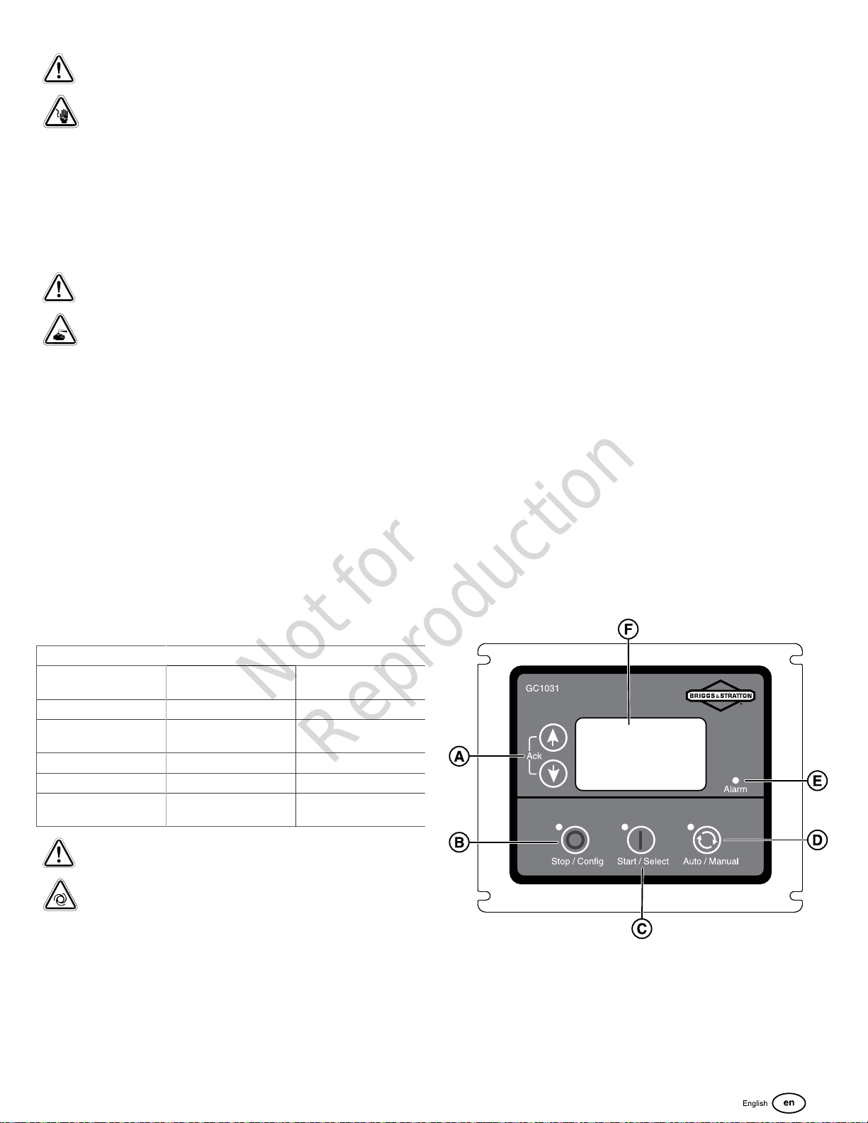
The generator control panel, located inside the generator
housing, is shown below.Brief descriptions of the controls
used during installation are:
(A) Menu / Programming Navigation Buttons
(B) Stop / Config Button
(C) Start / Select Button
(D) Auto / Manual Button
(E) Alarm
(F) Digital Display — Displays generator mode, menu options,
and alarms.
Detailed descriptions of the controls are located in
theDescription of Control Keyssection insidethe
online"Operation InstructionsGC1031GENSET
Controller"manual(part number80086364).
WARNING
With the battery connected, the generator may crank
and start without warning resulting in death or serious injury.
• Do not connect the negative (-) cable at the battery until
the installation is complete.
23
Page 24

Initial Start-Up (No Load)
Not for
Reproduction
WARNING
Exhaust heat/gases could ignite combustibles causing a fire, resulting in death or serious injury.
• Remove all combustible materials from in and around the generator compartment.
The unit has been set-up for NG operation at the factory. Fuel conversion, if needed, must be completed prior to performing
these steps. See Fuel Conversion.
Before operating the standby generator or placing it into service, inspect the entire installation carefully. Then begin testing the
system without any electrical loads connected, as follows:
NOTICE When the generator is started for the very first time, it will require that any air in the gaseous fuel lines be purged.
This can cause the engine to run roughly for a few minutes.
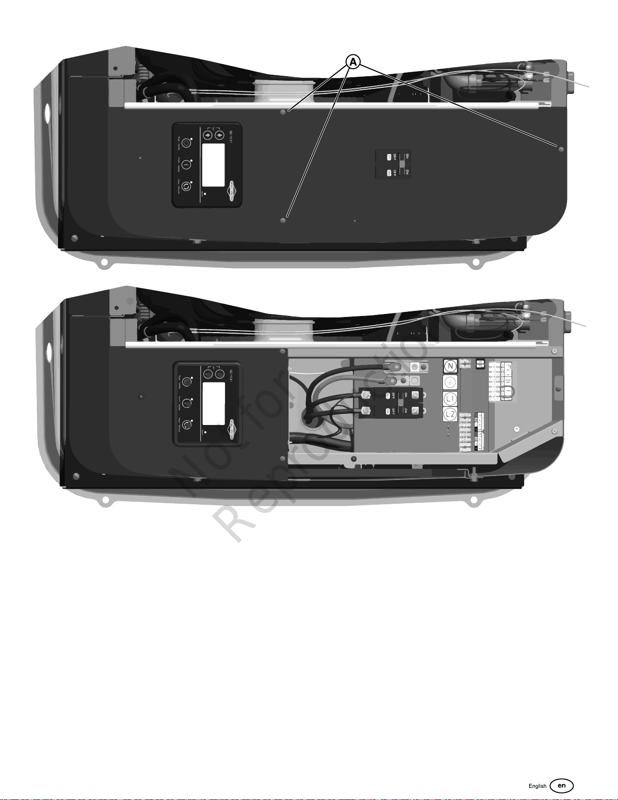
1. Remove three screws (A) that secure control box cover to enclosure to expose unit’s circuit breaker.
2. Connect an accurate multi-meter to line side of generator’s main circuit breaker.
3. Set generator’s main circuit breaker to ON (closed) position.
4. Remove the battery panel.
5. Install 15 Amp fuse in the fuse holder behind the battery panel.
6. Push the ON/OFF Switch on the back of the generator to the “ON” (I) position.
7. Push the START/SELECT button on the control board. The engine will start in Low Idle Mode (LIM). Push again to bring
the engine to full speed.
8. Listen for unusual noises, vibration or other indications of abnormal operation. Check for oil leaks while engine runs.
9. Let engine warm up for approximately 5 minutes to allow internal temperatures to stabilize.
10. Check generator output at load side of circuit breaker. Voltage should be 225 ‑ 250 Volts, frequency should be 59.0 ‑ 61.0
Hz.
11. Check generator output between one generator connection lug and neutral lug, then between other generator connection
lug and neutral lug. In both cases, voltage reading should be between 112 and 125 Volts.
12. Push the STOP/CONFIG button on the control board. The engine will enter cool-down mode for approximately 5 minutes.
Push again to stop the engine.
13. Install control box cover again.
14. Install the battery panel.
24
Page 25
Not for
Reproduction
25
Page 26
Operation
Not for
Reproduction
Features and Controls - 17kW and 20kW Generators
WARNING
Failure to read and obey the operator’s manual, all warnings, and operating instructions could result in death or
serious injury.
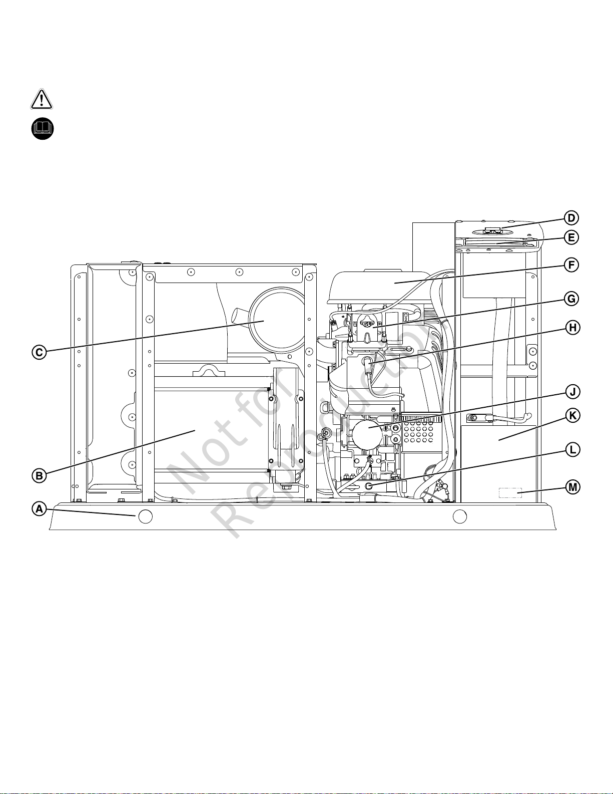
17kW and 20kW Generator (Front View)
Generator is shown with roof and access covers removed for clarity.
Legend for System Connector Locations:
(A) Lifting Holes — Provided at each corner for lifting generator.
(B) Alternator — An electrical machine that generates an alternating current
(C) Muffler — High-performance muffler lowers engine noise to comply with most residential codes.
(D) Circuit Breaker — Protects the system from shorts and other over-current conditions.
(E) Control Board — Used for generator operation control, menu start-up, and informational display functions.
(F) Air Cleaner — Uses a dry type filter element to protect engine by filtering dust and debris out of intake air
(G) Engine Label — Identifies engine model and type (located on the valve cover).
(H) Spark Plug — A device in the cylinder head of the engine that ignites the fuel mixture by means of an electric spark.
(J) Oil Filter — Filters engine oil to prolong generator life.
(K) Battery (installer supplied) — 12 Volt DC, lead acid, automotive style battery provides power to start the engine.
26
Page 27
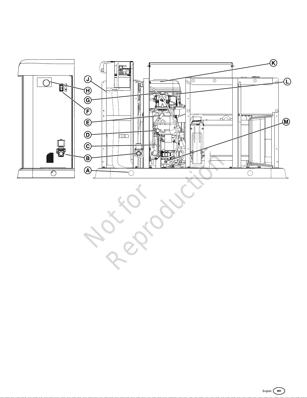
(L) Oil Drain Hose — Provided to facilitate oil changing.
Not for
Reproduction
(M) Generator Data Label — Identifies generator model number and serial number. Located inside battery access
compartment.
17kW and 20kW Generator (Back View)
(A) Lifting Holes — Provided at each corner for lifting generator.
(B) Fuel Solenoid — Automatically opens and closes to supply fuel to unit when needed.
(C) Fuel Regulator — Controls fuel flow to engine for proper operation.
(D) Fuel Selector Valve — Used to select proper fuel type (LP or NG).
(E) Spark Plug — A device in the cylinder head of the engine that ignites the fuel mixture by means of an electric spark.
(F) ON/ OFF Switch — Used to turn the generator on (I) and off (0).
(G) Oil Fill Cap — Location for adding oil to engine.
(H) Electrical Field Wiring Inlet — Wires to and from generator are centered in this location.
(J) Fuse Holder— For the 15 Amp ATO-type fuse (fuse holder is located in the upper battery bay).
(K) Air Cleaner — Uses a dry type filter element to protect engine by filtering dust and debris out of intake air.
(L) Engine Oil Dipstick — Allows user to check engine oil level easily.
(M) Oil Heater — Provided to warm engine oil to promote easy starting in cold climates.
27
Page 28
Important Owner's Considerations
Not for
Reproduction
WARNING
voltage is restored above a preset voltage level, the engine
is signaled to shut down. The actual system operation is not
adjustable and is sequenced by sensors and timers on the
control board, as follows:
Utility Voltage Dropout Sensor
Engine exhaust contains carbon monoxide, a
poisonous gas that could kill you in minutes. You cannot
smell it, see it, or taste it. Even if you do not smell exhaust
fumes, you could still be exposed to carbon monoxide gas.
• Carbon monoxide detector(s) MUST be installed and
maintained indoors according to the manufacturer’s
instructions/recommendations. Smoke alarms cannot
detect carbon monoxide gas.
• If you start to feel sick, dizzy, weak, or your carbon
monoxide alarm sounds while using this product, get to
fresh air right away. Call emergency services. You may
have carbon monoxide poisoning.
WARNING
Propane and Natural Gas are extremely flammable
and explosive, which could cause burns, fire or explosion
resulting in death or serious injury.
• The generator is equipped with an automatic safety
gasfuel shut-off valve.
• DO NOT operate the equipment if the fuel shut-off valve
is missing or inoperative.
Engine Oil
The engine is shipped from the factory pre-run and filled
with synthetic oil (API SJ/CF 5W-30). This allows for system
operation in a wide range of temperature and climate
conditions. Before starting the engine, check the oil level as
described inMaintenance.
NOTICE Any attempt to crank or start the engine without
being correctly filled with the recommended oil will result in
equipment failure.
• This sensor monitors the utility source voltage.
• If the utility source voltage dropsbelowapproximately70
percent of the nominal supply voltage, the sensor initiates
a timer. The timer is used to ‘sense’ brown‑outs.
• Once the timer has expired, the engine will crank and
start.
Utility Voltage Pickup Sensor
This sensor monitors the utility voltage. When the utility
voltage is restoredaboveapproximately80 percent of the
nominal source voltage, a shut-down timer is initiated and the
engine will go to engine cool-down.
Engine Cool-down Timer
When the utility power is sensed, the load transfers to the
utility source and the engine will go into a 5 minute cool down
period.
Setting the Exercise Timer
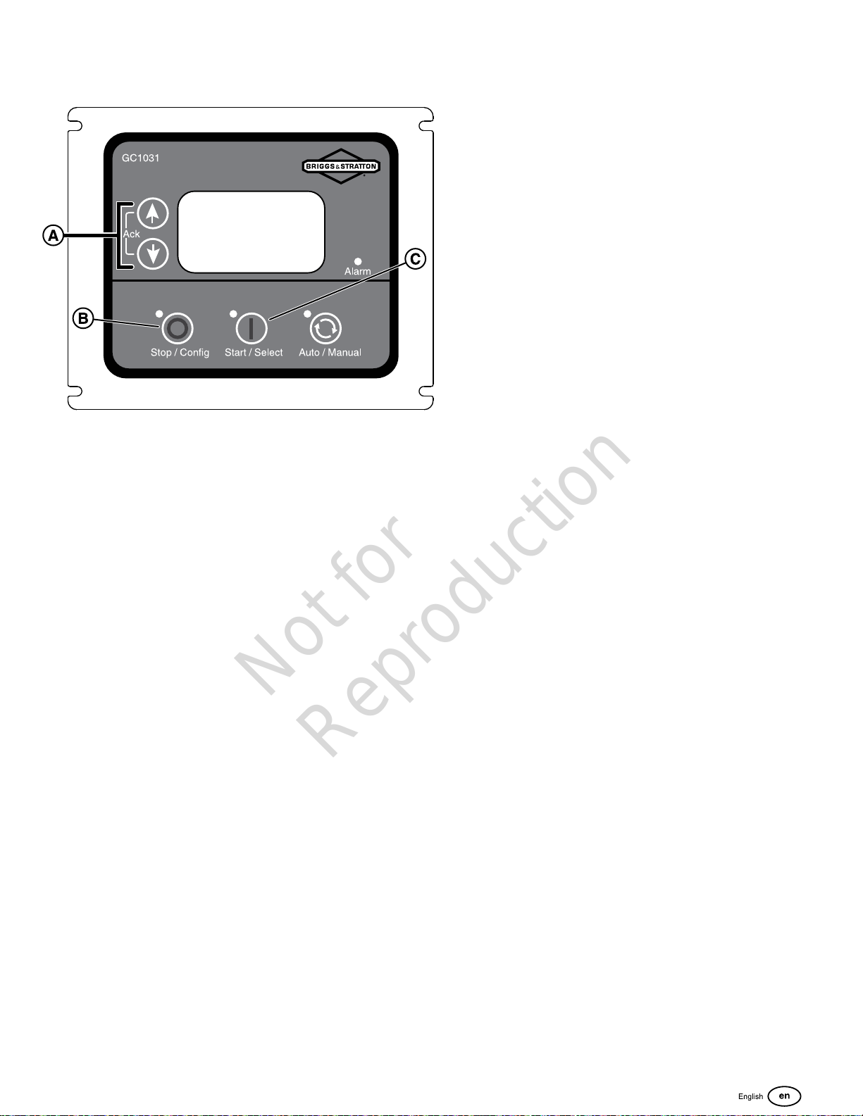
1. Push and hold the Stop/Config button (B).
2. Push the Start/Select button (C) to enter WRITE MODE.
3. Enter the password (0000) by using the arrow keys (A)
and theStart/Select button (C).
4. In the CONFIGURATION screen use the arrow keys (A)
to find MODULE.
5. Push theStart/Select button (C)and using thearrow keys
(A) find AUTO EXERCISE.
6. Push theStart/Select button (C)and using thearrow
keys (A)select each parameter and choose the desired
settings.
7. To save your settings when completed, push and hold
theStop/Config button (B) until "Saving Settings" shows
on the display.
• Damage to equipment resulting from failure to obey this
instruction will void engine and generator warranty.
Battery
The installer must supply a rechargeable 12 volt DC starting
battery. See Battery inFinal Installation Considerationsin this
manual.
15 Amp Fuse
Make sure that the fuse is correctly installed before operating
your generator.
Automatic Operation Sequence
The generator’s control board monitors utility voltage. If the
utility voltage drops below a preset level, the control board
will signal the engine to crank and start. When the utility
28
Page 29
A detailed list of all the on screen parameters is located in
Not for
Reproduction
theConfiguration of GCUsection insidethe online"Operation
InstructionsGC1031GENSET Controller"manual(part
number80086364)
29
Page 30

Maintenance
Not for
Reproduction
Servicing the System
Check the Valve Clearance
Check the Circuit Breaker Torques
Annually
Clean the Oil Cooler Fins
WARNING
Generatorand utilityvoltage could cause electrical
shock or burn resulting in death or serious injury.
• DO NOT allow unqualified persons to operate or
servicethis equipment.
WARNING
With the battery connected, the generator may crank
and start without warning resulting in death or serious injury.
• Before servicing, stop the generator and disconnect the
negative (-) cable at the battery.
Before performing any generator maintenance, always do the
following steps
1. Push the ON/OFF Switch on the back of the generator to
the “OFF” (0) position.
2. Remove utility power to the generator to de-energize the
battery charger.
3. Unlock and open the roof as described in theAccess
Panelssection of this manual.
4. Remove the battery panel.
5. Remove the 15 Amp fuse from the fuse holder located
behind the battery panel.
6. Disconnect the negative (-) cable at the battery.
7. Perform service steps as specified.
8. Connect the negative (-) cable at the battery.
9. Install the 15 Amp fuse into the fuse holder.
10. Install the battery panel.
11. Close and lock the roof.
12. Restore utility power to the generator.
13. Push the ON/OFF Switch on the back of the generator to
the “ON” (I) position.
14. Set the generator mode to AUTO.
Maintenance Schedule
Follow the hourly or calendar intervals of operation,
whichever occurs first.
Every 8 Hours of Operation or Daily
Clean Debris
Check the Engine Oil Level
Every 100 Hours of Operation or Annually
Change the Air Filter
Change the Engine Oil and Filter
Replace the Spark Plugs
Regular maintenance will improve the performance and
extend the life of the generator. See any authorized dealer for
service.
Emissions Control
Maintenance, replacement, or repair of the emissions control
devices and systems can be done by any non-road engine
repair establishment or an individual. However, to obtain "no
change" emissions control service, the work must be done by
a factory authorized dealer. See the Emissions Warranty.
Generator Maintenance
The generator’s warranty does not cover items that have
been subjected to operator abuse or negligence. To receive
full value from the warranty, the operator must maintain the
generator as instructed in this manual.
Some adjustments will need to be made periodically to
correctly maintain your generator.
All service and adjustments must be made at least once
each season. Obey the requirements in theMaintenance
Schedulechart.
Generator maintenance consists of keeping the unit clean.
Operate the unit in an environment where it will not be
exposed to excessive dust, dirt, moisture or any corrosive
vapors. The cooling air louvers on the enclosure must not
become clogged with snow, leaves, or other foreign material.
To prevent generator damage caused by overheating,
keep the enclosure cooling inlets and outlets clean and
unobstructed at all times.
Check the cleanliness of the unit frequently and clean when
dust, dirt, oil, moisture or other foreign substances are visible
on its exterior/interior surface. Inspect the air inlet and outlet
openings inside and outside the enclosure to make sure the
air flow is not blocked.
NOTICE Incorrect treatment of generator can damage it
and shorten its life.
• DO NOT expose generator to excessive moisture, dust,
dirt, or corrosive vapors.
• DO NOT insert any objects through cooling slots.
Cleaning the Generator
30
Page 31
WARNING
Not for
Reproduction
Exhaust heat/gases could ignite combustibles
causing a fire, resulting in death or serious injury.
• Keep the area near the generator clean and free of
debris.
NOTICE DO NOT use direct spray from a garden hose to
clean generator. Water can enter the engine and generator
and cause damage.
NOTICE Periodically inspect the engine exterior for
contamination and potential damage from dirt, leaves,
rodents, spider webs, insects, etc. and remove.
1. Push the ON/OFF Switch on the back of the generator to
the “OFF” (0) position.
2. Remove utility power to the generator to de-energize the
battery charger.
3. Unlock and open the roof as described in theAccess
Panelssection of this manual.
4. Remove the battery panel.
5. Remove the 15 Amp fuse from the fuse holder located
behind the battery panel.
6. Disconnect the negative (-) cable at the battery.
7. Clean generator as follows: Use a damp cloth to wipe
exterior surfaces clean. Use a soft, bristle brush and
vacuum cleaner to loosen and pick up dirt and debris.
Use low pressure air (not to exceed 25 psi) to blow away
dirt and debris. Clean the air inlets and outlets of any
snow, leaves, or debris. To prevent generator damage
caused by overheating, these openings must be kept
unobstructed.
8. Connect the negative (-) cable at the battery.
9. Install the 15 Amp fuse into the fuse holder.
10. Install the battery panel.
11. Close and lock the roof.
12. Restore utility power to the generator.
13. Push the ON/OFF Switch on the back of the generator to
the “ON” (I) position.
14. Set the generator mode to AUTO.
Engine Maintenance
Engine Oil
Use only Briggs & Stratton® 80028446 SAE 5W-30 full
synthetic engine oil.
Checking Engine Oil Level
Oil must be maintained between the “ADD” and the “FULL”
marks on the dipstick. To make sure that an accurate reading
is shown on the dipstick, make sure the following steps are
taken before checking the oil level.
1. Push the ON/OFF Switch on the back of the generator to
the “OFF” (0) position.
2. Remove utility power to the generator to de-energize the
battery charger.
3. Unlock and open the roof as described in theAccess
Panelssection of this manual.
4. Remove the battery panel.
5. Remove the 15 Amp fuse from the fuse holder located
behind the battery panel.
6. Disconnect the negative (-) cable at the battery.
7. Allow approximately five minutes for the oil to drain back
into the oil pan.
8. Remove the dipstick. Wipe it with a clean cloth or paper
towel. Then, push the dipstick all the way into the dipstick
tube.
9. Remove the dipstick and note the amount of oil on the
dipstick. The oil level must be between the “ADD” and
“FULL” marks.
10. If the oil level is below the “ADD” mark, install the dipstick
and proceed to step 8.
11. Remove the oil filler cap from the valve cover.
12. Add the required amount of oil to bring the level up to, but
not over, the “FULL” mark on the dipstick. Install the oil
filler cap to the valve cover and wipe up any spilled oil.
13. Connect the negative (-) cable at the battery.
14. Install the 15 Amp fuse into the fuse holder.
15. Install the battery panel.
16. Close and lock the roof.
17. Restore utility power to the generator.
18. Push the ON/OFF Switch on the back of the generator to
the “ON” (I) position.
19. Set the generator mode to AUTO.
Changing Engine Oil and Oil Filter
Change the oil while the engine is still warm from running.
31
Page 32

1. Push the ON/OFF Switch on the back of the generator to
Not for
Reproduction
the “OFF” (0) position.
2. Remove utility power to the generator to de-energize the
battery charger.
3. Unlock and open the roof as described in theAccess
Panelssection of this manual.
4. Remove the battery panel.
5. Remove the 15 Amp fuse from the fuse holder located
behind the battery panel.
6. Disconnect the negative (-) cable at the battery.
7. Place the oil drain hose into an approved container.
8. Remove the brass fitting from the end of the oil drain
hose.
9. When the oil has drained, replace the brass fitting on the
hose.
10. Put an approved container beneath the oil filter area.
11. Remove the oil filter and dispose of it correctly.
12. Before installing a new oil filter, lightly lubricate the oil
filter gasket with fresh and clean oil.
13. Install the oil filter by hand until the gasket contacts the oil
filter adapter, then tighten the oil filter ½ to ¾ turn.
14. Add the required amount of oil to bring the level up to, but
not over, the “FULL” mark on the dipstick. Install the oil
filler cap and wipe up any spilled oil.
15. Connect the negative (-) cable at the battery.
16. Install the 15 Amp fuse into the fuse holder.
17. Install the battery panel.
18. Close and lock the roof.
19. Restore utility power to the generator.
20. Push the ON/OFF Switch on the back of the generator to
the “ON” (I) position.
21. Set the generator mode to AUTO.
Engine Oil
The engine is filled with synthetic oil (API SJ/CF 5W-30).
This allows for system operation in the widest range of
temperature and climate conditions.
We recommend the use of Briggs & Stratton®80028446 SAE
5W-30 full synthetic engine oil.Other high-quality detergent
oils are acceptable if classified for service SJ or higher. Do
not use special additives.
Note:Synthetic oil meeting ILSAC
GF-2, API certification mark and API
service symbol with “SJ/CF ENERGY
CONSERVING” or higher, is an
acceptable oil at all temperatures.
Use of synthetic oil does not alter
required oil change intervals.
Adjust Valve Lash
The valve lash must be checked every 100 hours of
operation. Measure the valve clearance with the engine cold.
To adjust the valve lash, proceed as follows:
1. Push the ON/OFF Switch on the back of the generator to
the “OFF” (0) position.
2. Remove utility power to generator to de-energize the
battery charger.
3. Unlock and open the roof as described in theAccess
Panelssection of this manual.
4. Remove the battery panel.
5. Remove the 15 Amp fuse from the fuse holder located
behind the battery panel.
6. Disconnect the negative (-) cable at the battery.
7. Remove both spark plugs to ease manual rotation of
engine crankshaft.
8. Access to rotate the engine by hand is available by:
A. Removing the engine intake screen in the battery
compartment such that the crankshaft nut is
accessible. Care must be taken when reassembling
this screen using the self tapping screws as overtorqueing will strip out the partition material.
B. OR remove the front alternator outlet air scoop
by removing the four screws that secure it. The
crankshaft may be rotated via the aluminum
alternator fan. Care should be taken not to damage
the fan, and to reinstall the alternator outlet air scoop
in the proper orientation.
9. Set the No. 1 cylinder at ¼” (6mm) past Top Dead Center
(TDC) on the compression stroke.
10. Using a feeler gage (A), measure the valve clearance.
11. For proper valve clearance for both the intake and
exhaust seeEngine SpecificationsSection
12. Adjust the clearance by loosening the lock nut (B), then
turn the adjusting screw (C).
13. Once the clearance is properly set, hold the adjusting
screw while torqueing the lock nut to 70 in-lbs (8Nm).
14. Repeat these steps for cylinder No. 2.
15. Connect the negative (-) cable at the battery.
16. Install the 15 Amp fuse into the fuse holder.
17. Install the battery panel.
18. Close and lock the roof.
19. Restore utility power to the generator.
20. Push the ON/OFF Switch on the back of the generator to
the “ON” (I) position.
21. Set the generator mode to AUTO.
32
Page 33
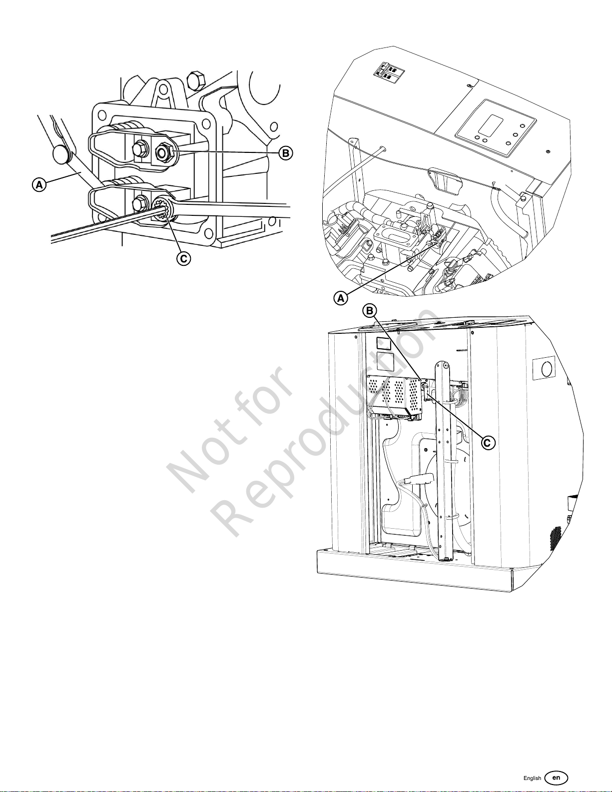
Electronic Governor System
Not for
Reproduction
The engine electronic governor system allows for improved
control and increased generator performance compared
to mechanically governed systems. The result is a smooth
steady-state operation without the “hunting” common to
many mechanical governors. The system also reduces
speed variations under engine loading and unloading and
significantly reduces frequency fluctuation experienced when
the engine is under higher loads.
The electronic governor system is composed of a stepper
motor (B), stepper motor throttle control linkages (C), and
throttle side linkage (A). The control board contains a digital
controller that processes engine speed information and sends
appropriate commands to the stepper motor to control the
position of the engine throttle.
Since the electronic governing system controls the engine
throttle demand based on generator load, the following
service codes and/or conditions can be related to an
electronic governing system issue:
• Engine Does Not Start
• Over Speed
• Under Frequency
• Unstable No Load Engine Control
While troubleshooting any of these conditions, a verification
of the electronic governor system can be initiated through the
control panel – Actuator Test.
Electronic Governing Check
The generator has an electronic governing check feature that
will turn on the stepper motor and move the throttle linkage
clockwise and counterclockwise within the throttle limits. The
test will rotate the stepper motor and move the throttle arm
between the wide open throttle and dead idle limits for up to
10 seconds. This will allow visual verification that the stepper
motor is functioning correctly and the control linkages are
connected. The engine will not attempt to start during this
test. If the stepper motor does not move, or if a linkage binds,
then service willbe required.
33
Page 34
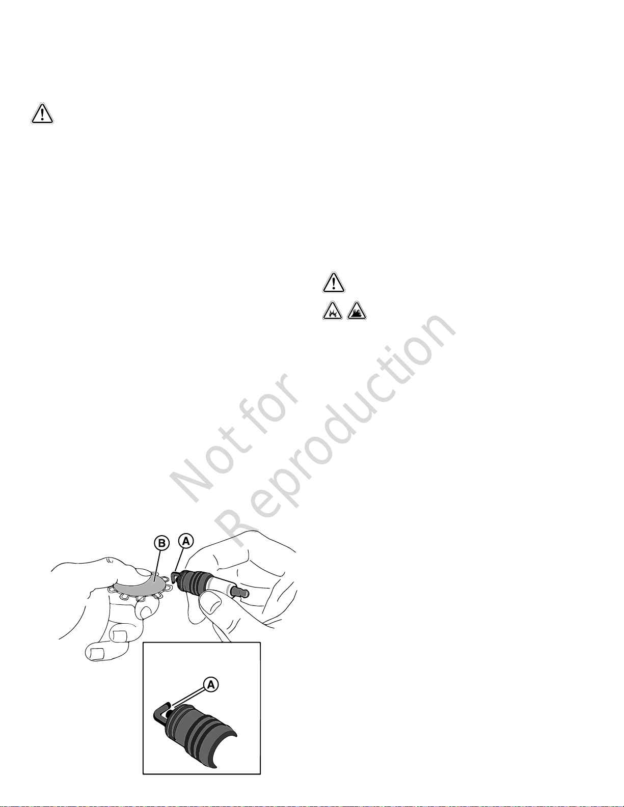
NOTICE If stepper motor does not move, please make
Not for
Reproduction
sure the stepper motor connector is attached.
Service the Spark Plugs
WARNING
Unintentional sparking could cause fire or electric shock
resulting in death or serious injury.
WHEN ADJUSTING OR MAKING REPAIRS TO YOUR
GENERATOR
• Disconnect the spark plug wire from the spark plug and
place the wire where it cannot contact spark plug.
WHEN TESTING FOR ENGINE SPARK
• Use approved spark plug tester.
• DO NOT check for spark with spark plug removed.
10. Replace the spark plugs if the electrodes are
pitted, burned or the porcelain is cracked. Use the
recommended replacement spark plugs(seeEngine
Specificationsat the end of this manual).
11. Install the spark plugs and tighten them to 180 in/lbs (20
Nm).
12. Connect the negative (-) cable at the battery.
13. Install the 15 Amp fuse into the fuse holder.
14. Install the battery panel.
15. Close and lock the roof.
16. Restore utility power to the generator.
17. Push the ON/OFF Switch on the back of the generator to
the “ON” (I) position.
18. Set the generator mode to AUTO.
Engine Air Cleaner
Changing the spark plugs will help your engine to start easier
and operate better.
1. Push the ON/OFF Switch on the back of the generator to
the “OFF” (0) position.
2. Remove utility power to the generator to de-energize the
battery charger.
3. Unlock and open the roof as described in theAccess
Panelssection of this manual.
4. Remove the battery panel.
5. Remove the 15 Amp fuse from the fuse holder located
behind the battery panel.
6. Disconnect the negative (-) cable at the battery.
7. Clean the area around spark plugs.
8. Remove and inspect spark plugs.
9. Check electrode gap (A) with wire feeler gauge (B) and
reset spark plug gap to recommended gap if necessary
(seeEngine Specificationsat the end of this manual).
WARNING
Gaseous vapors are extremely flammable and
explosive. Fire or explosion can cause severe burns or
death.
• Never start and run the engine with the air cleaner
assembly (if equipped) or the air filter (if equipped)
removed.
1. Push the ON/OFF Switch on the back of the generator to
the “OFF” (0) position.
2. Remove utility power to the generator to de-energize the
battery charger.
3. Unlock and open the roof as described in theAccess
Panelssection of this manual.
4. Remove the battery panel.
5. Remove the 15 Amp fuse from the fuse holder located
behind the battery panel.
6. Disconnect the negative (-) cable at the battery.
7. Remove filter cartridge.
8. Clean the outlet tube and check the Dust Unloader Valve
(if equipped) - Use a clean cloth to wipe the filter sealing
surface and the outlet tube surfaces. Make sure that all
contaminant is removed before the new filter is inserted.
Do not damage the sealing area on the tube. Check and
squeeze the Dust Unloader Valve that is attached to the
service cover to make sure it is flexible and not inverted,
damaged orplugged.
9. Clean the filter - Use a soft bristle brush to loosen dirt and
a vacuum cleaner to remove dirt and debris. Replace the
filter cartridge if you find any holes in the filter media.
10. Install the clean filter correctly - Insert the filter carefully.
Seat the filter by hand. Make sure it is completely seated
in the air cleaner housing before you put the cover in
place.
11. Install the service cover. Make sure that all mounting
bands, clamps, bolts, and connections in the entire air
34
Page 35
cleaner system are tight and make sure there are no
Not for
Reproduction
holes in piping - repair if needed.
12. Connect the negative (-) cable at the battery.
13. Install the 15 Amp fuse into the fuse holder.
14. Install the battery panel.
15. Close and lock the roof.
16. Restore utility power to the generator.
17. Push the ON/OFF Switch on the back of the generator to
the “ON” (I) position.
18. Set the generator mode to AUTO.
Exhaust System Maintenance
If the regulator fails to operate or develops a leak, it must
be repaired or replaced with the OEM recommended
replacement parts. When inspecting the regulator, check the
following:
• Check for any fuel leaks at the inlet and outlet fittings.
• Check for any fuel leaks in the regulator body.
• Check to make sure the regulator is correctly mounted
and the mounting bolts are tight.
• Check the regulator for external damage.
Mixer/Throttle Control Device
The mixer and throttle body components have been
specifically designed and calibrated to meet the fuel system
requirements of the engine.
WARNING
Contact with muffler area could cause burns resulting
in serious injury.
• DO NOT touch hot parts and AVOID hot exhaust gases.
• Allow equipment to cool before touching.
When inspecting the exhaust system, check the following:
• Inspect the exhaust manifold at the cylinder head for
leaks.
• Check that all retaining bolts and shields (if used) are in
place.
• Inspect the fasteners between the manifold and the
exhaust pipe to make sure they are tight and that there
are no exhaust leaks. Repair as necessary.
• Inspect exhaust pipe connection for leaks. Repair as
necessary.
It is a violation of California Public Resource Code, Section
4442, to use or operate the engine on any forest-covered,
brush-covered, or grass-covered land unless the exhaust
system is equipped with a spark arrester, as defined in
section 4442, maintained in effective working order. Other
states or federal jurisdictions may have similar laws;
reference Federal Regulation 36 CFR Part 261.52.
Fuel System Maintenance
A dirty air filter can significantly alter the mixer performance.
Make sure the air filter is clean. When inspecting the mixer
and throttle body, check the following:
• Check for leaks at all the fittings.
• Make sure the mixer and throttle body are securely
mounted.
• Inspect and clean the air filter element according to the
recommended service intervals listed in the maintenance
chart.
• Inspect air inlet hose connection and clamp. Inspect hose
for cracking, splitting, or chafing. Replace as necessary.
• Check fuel lines for cracking, splitting, or chafing. Replace
as necessary.
• Check for leaks at the throttle body and intake manifold.
Alarms (Service Code Detection System)
The generator will have to run for long periods of time with
no operator present. For that reason, the system is equipped
with sensors that automatically shut down the generator in
the event of potentially damaging conditions, such as low oil
pressure, high temperature, over speed, and other conditions.
The generator’s control board shows service alarm
descriptions on the digital display. The service alarm
descriptions are listedin the"Alarms"section insidethe
online"Operation InstructionsGC1031GENSET
Controller"manual(part number80086364).
WARNING
Propane and Natural Gas are extremely flammable
and explosive, which could cause burns, fire or explosion
resulting in death or serious injury.
• Inspect the fuel system periodically.
• NO leakage is permitted.
• DO NOT operate engine if smell of fuel is present.
Pressure Regulator
The pressure regulator components have been specifically
designed and calibrated to meet the fuel system requirements
of the engine.
Acknowledge and Reset the Alarms
(Service Code Detection System)
Push the up and down arrows (A) simultaneously to reset the
alarm.
35
Page 36
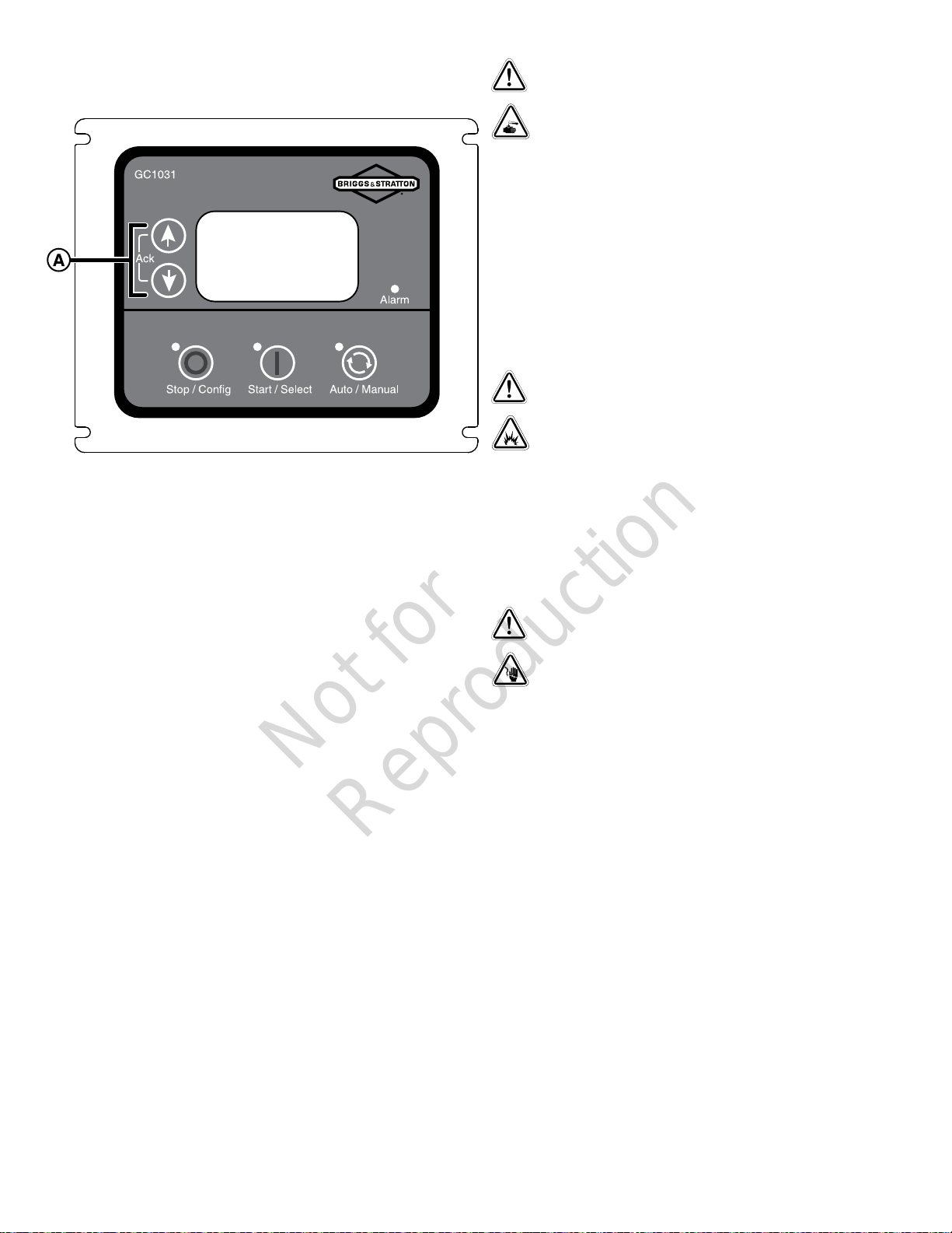
Electrical System Maintenance
Not for
Reproduction
Wiring and Connections
The generator electrical system incorporates computers to
control various components. The electrical system connectors
and grounds require good connections. When inspecting the
electrical system, check the following:
WARNING
Battery electrolyte fluid contains acid and is extremely
caustic. Contact with battery contents could cause severe
chemical burns.
• DO NOT open or mutilate the battery
• Wear protective goggles, rubber apron, rubber boots
and rubber gloves.
• Immediately wash electrolyte from skin with water.
• If electrolyte contacts eyes, immediately flush with
water and seek medical attention.
• Spilled electrolyte is to be washed down with an acid
neutralizing agent.
WARNING
Storage batteries give off explosive hydrogen gas
during recharging. Slightest spark could ignite hydrogen
and cause explosion, resulting in death or serious injury.
• DO NOT dispose of battery in a fire. Recycle battery.
• DO NOT allow any open flame, spark, heat, or lit
cigarette during and for several minutes after charging a
battery.
WARNING
• Check the positive (+) and the negative (-) battery cables
for corrosion, rubbing, chafing, burning, and make sure
there are tight connections at both ends.
• Check the battery for cracks or damage to the case.
Replace as necessary.
• Inspect the engine wire harness for rubbing, chafing,
pinching, burning, and cracks or breaks in the wiring.
• Make sure that the engine harness connectors are
correctly locked in.
• Inspect the ignition coil wire for hardening, cracking,
chafing, burning, separation, and split boot covers.
• Inspect the spark plug wires for hardening, cracking,
chafing, burning, separation, and split boot covers.
• Replace the spark plugs at the required intervals listed in
the maintenance chart.
• Make surethat all electrical components are securely
mounted to the engine or chassis.
• Make sure that any additional electrical services installed
by the owner are correctly installed in the system.
Servicing the Battery
Servicing of the batteries is to be performed or supervised
by personnel knowledgeable of batteries and the required
precautions. Keep unauthorized personnel away from the
batteries.
A battery presents a risk of high short circuit current.
• Remove watches, rings, or other metal objects.
• Use tools having insulated handles.
• Disconnect charging source prior to connecting or
disconnecting battery terminals.
• Do not lay tools or metal parts on top of batteries.
• Disconnect the negative (-) cable at the battery during
installation and maintenance.
1. Push the ON/OFF Switch on the back of the generator to
the “OFF” (0) position.
2. Remove utility power to the generator to de-energize the
battery charger.
3. Unlock and open the roof as described in theAccess
Panelssection of this manual.
4. Remove the battery panel.
5. Remove the 15 Amp fuse from the fuse holder located
behind the battery panel.
6. Disconnect the negative (-) cable at the battery.
7. Disconnect the positive (+) cable at the battery.
8. Service or replace the battery as required.
9. Connect the positive (+) cable at the battery.
10. Connect the negative (-) cable at the battery.
11. Install the 15 Amp fuse into the fuse holder.
36
Page 37

12. Install the battery panel.
Not for
Reproduction
13. Close and lock the roof.
14. Restore utility power to the generator.
15. Push the ON/OFF Switch on the back of the generator to
the “ON” (I) position.
16. Set the generator mode to AUTO.
Replacing the Battery
1. Push the ON/OFF Switch on the back of the generator to
the “OFF” (0) position.
2. Remove utility power to the generator to de-energize the
battery charger.
3. Unlock and open the roof as described in theAccess
Panelssection of this manual.
4. Remove the battery panel.
5. Remove the 15 Amp fuse from the fuse holder located
behind the battery panel.
6. Disconnect the negative (-) cable at the battery.
7. Disconnect the positive (+) cable at the battery.
8. Remove the battery and install replacement battery.
7. Charge battery with the battery charger at 2 Amps until
the battery holds 12 Volts. DO NOT exceed 13.7 volts
when charging the battery.
NOTICE DO NOT use a battery booster to quick charge a
low battery.
8. Connect the negative (-) cable at the battery.
9. Install the 15 Amp fuse into the fuse holder.
10. Install the battery panel.
11. Close and lock the roof.
12. Restore utility power to the generator.
13. Push the ON/OFF Switch on the back of the generator to
the “ON” (I) position.
14. Set the generator mode to AUTO.
DON'T POLLUTE. CONSERVE RESOURCES.
RETURN USED BATTERY TO RECYCLING
COLLECTION CENTER.
9. Connect the positive (+) cable at the battery.
10. Connect the negative (-) cable at the battery.
11. Install the 15 Amp fuse into the fuse holder.
12. Install the battery panel.
13. Close and lock the roof.
14. Restore utility power to the generator.
15. Push the ON/OFF Switch on the back of the generator to
the “ON” (I) position.
16. Set the generator mode to AUTO.
Charging the Battery
If it is necessary to charge the battery, proceed as follows:
1. Push the ON/OFF Switch on the back of the generator to
the “OFF” (0) position.
2. Remove utility power to the generator to de-energize the
battery charger.
3. Unlock and open the roof as described in theAccess
Panelssection of this manual.
4. Remove the battery panel.
5. Remove the 15 Amp fuse from the fuse holder located
behind the battery panel.
6. Disconnect the negative (-) cable at the battery.
NOTICE Failure to disconnect negative battery cable
could result in equipment failure.DO NOT attempt to
jump start the generator.Damage to equipment resulting
from failure to follow this instruction will void engine and
generator warranty.
37
Page 38

Troubleshooting
Not for
Reproduction
InstructionsGC1031GENSET Controller"manual(part
number80086364)
The service alarm descriptions and their causes are listedin
the table of the "Alarms" section insidethe online"Operation
Troubleshooting
PROBLEM CAUSE CORRECTION
Engine is running, but no AC output is available.
Engine runs well at no-load but “bogs down” when
loads are connected.
Engine will not start; or starts and runs rough
Engine shuts down during operation.
Loss of power on circuits.
Unit will not exercise.
Excessive Vibration
Odor of fuel
Utility power returns, unit does not stop
Possible issues in MANUAL MODE See Table 7 (Common faults and
1. Circuit breaker is open or defective.
2. Alarm on generator control board.
3. Poor wiring connections or defective transfer
switch.
1. Generator is overloaded.
2. Short circuit in a connected load.
3. Shorted generator circuit.
4. Fuel pressure or mixture is incorrect.
5. Kinked fuel line between regulator and
engine.
6. Clogged air filter.
1. 15 Amp fuse missing or blown.
2. Thermal fuse(s) blown.
3. Fuel supply turned off or depleted.
4. Incorrect fuel selection.
5. Failed battery.
6. Clogged air filter.
7. Throttle linkage binding
1. Fuel supply turned off or depleted.
2. Control board digital display shows an
alarm.
1. Generator circuit breaker is open.
2. Transfer switch problems.
1. Control board not set to AUTO.
2. Exercise timer not set or set to OFF.
3. Unit date and time not set.
4. Failed battery.
5. 15 Amp fuse missing or blown.
1. Loose mechanical fastener. 1. Check and repair or contact local service
1. Fuel leak. 1. Turn off manual shutoff fuel valve. Contact
1. Blown fuses in transfer switch.
2. 5 minute cool down not lapsed.
3. Poor wire connection or defective
controllers.
their remedial actions) insidethe
online"Operation InstructionsGC1031GENSET
Controller"manual(part number80086364).
1. Reset or replace circuit breaker.
2. Refer toAlarms section
insidethe online"Operation
InstructionsGC1031GENSET
Controller"manual(part number80086364).
Contact local service facility.
3. Check and repair or contact local service
facility.
1. Remove one or more loads.
2. Disconnect shorted electrical load.
3. Contact local service facility.
4. SeeGaseous Fuel Systemin this manual.
5. Remove kink. Replace if necessary.
6. Clean or replace air filter.
1. Install (new) 15 Amp fuse. SeeSystem
Control Board
2. Replace thermal fuse(s).
3. Open fuel valve(s); check propane tank.
4. Check fuel selector switch and set to proper
setting. (If applicable)
5. Replace battery.
6. Clean or replace air filter.
7. Check linkage.
1. Check fuel valves, fill propane tank.
2. Refer toAlarms section
insidethe online"Operation
InstructionsGC1031GENSET
Controller"manual(part number80086364).
1. Reset circuit breaker.
2. See transfer switch manual.
1. Push AUTO button on control board.
2. Set exercise timer.
3. Set unit date and time.
4. Replace the battery.
5. Install a (new) 15 Amp fuse. SeeSystem
Control Board.
facility.
local service facility.
1. Install (new) fuses.
2. Wait 5 minutes.
3. Check, repair or contact local service
facility.
38
Page 39

Possible issues in AUTO MODE See Table 7 (Common faults and
Not for
Reproduction
Possible issues with Electronic Governing See Table 7 (Common faults and
their remedial actions) insidethe
online"Operation InstructionsGC1031GENSET
Controller"manual(part number80086364).
their remedial actions) insidethe
online"Operation InstructionsGC1031GENSET
Controller"manual(part number80086364).
39
Page 40
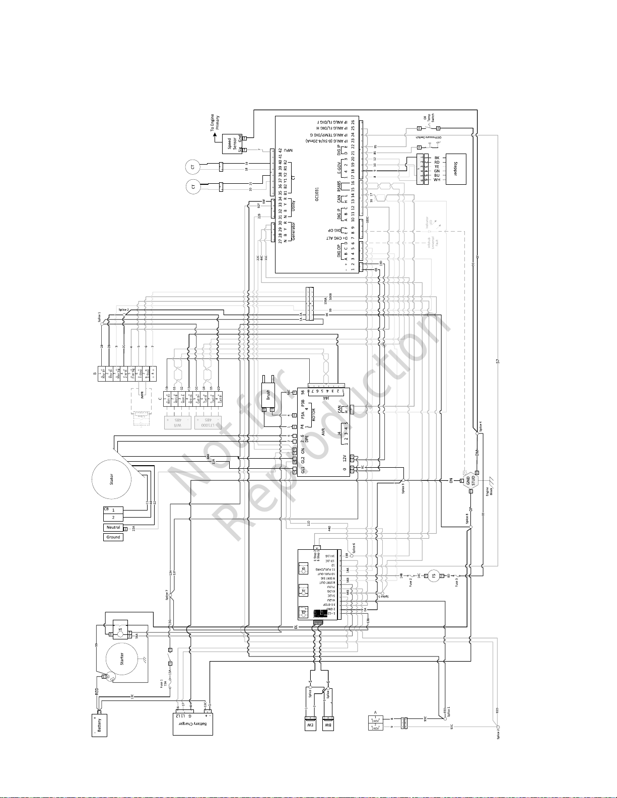
Diagrams and Schematics
Not for
Reproduction
Wiring Diagram and Schematic
40
Page 41

Specifications
Not for
Reproduction
Generator Specifications: 17kW and
20KW
* 17k Watt.
Oil Type 5W30 Synthetic
Oil Capacity (with filter) 78 - 80 oz. (2.3 - 2.4 L)
Engine End Cover Bolt 220 lb-in (25Nm)
Rated Maximum Load Current*(at
25°C/77°F, LP)*: at 240 Volts
Rated AC Voltage 120/240 Volts
Phase Single phase
Rated Frequency 60 Hertz
Generator Breaker 80 Amp
Normal Operating Range -20°F (-28.8°C) to 104°F (40°C)
Output Sound Level 69.1 dB(A) at 23 ft. (7 m) at normal
Shipping Weight 610 lb (278 kg)
* 20k Watt
Rated Maximum Load Current*(at
25°C/77°F, LP)*: at 240 Volts
Rated AC Voltage 120/240 Volts
Phase Single phase
Rated Frequency 60 Hertz
Generator Breaker 100 Amp
Normal Operating Range -20°F (-28.8°C) to 104°F (40°C)
Output Sound Level 69.1 dB(A) at 23 ft. (7 m) at normal
Shipping Weight 626 lb (278 kg)
70.8Amps
load
83.3 Amps
load
* Natural gas rating will depend on specific fuel but typical
derates are between 10 to 20% off the LP gas rating.
Engine Specifications
* 17k Watt.
Displacement 60.60 ci. (993 cc)
Bore 3.405 in. (86.5 mm)
Stroke 3.366 in. (85.5 mm)
Spark Plug Gap 0.020 in. (0.51 mm)
Spark Plug Torque 180 lb-in. (20 Nm)
Armature Air Gap 0.005 - 0.008 in. (0.13 - 0.20 mm)
Intake Valve Clearance 0.004 - 0.006 in. (0.10 - 0.15 mm)
Exhaust Valve Clearance 0.007 - 0.009 in. (0.15 - 0.23 mm)
Oil Type 5W30 Synthetic
Oil Capacity (with filter) 78 - 80 oz. (2.3 - 2.4 L)
Engine End Cover Bolt 220 lb-in (25Nm)
* 20k Watt.
Displacement 60.60 ci. (993 cc)
Bore 3.405 in. (86.5 mm)
Stroke 3.366 in. (85.5 mm)
Spark Plug Gap 0.020 in. (0.51 mm)
Spark Plug Torque 180 lb-in. (20 Nm)
Armature Air Gap 0.005 - 0.008 in. (0.13 - 0.20 mm)
Intake Valve Clearance 0.004 - 0.006 in. (0.10 - 0.15 mm)
Exhaust Valve Clearance 0.007 - 0.009 in. (0.15 - 0.23 mm)
41
Page 42

Not for
Reproduction
Page 43

Not for
Reproduction
Page 44

Not for
Reproduction
 Loading...