

Page 1
7KW DUAL-MODE BACKUP GENERATOR
Operator’s Manual
Manual del Operario
Manuel d’utilisation
SAVE THESE INSTRUCTIONS
Manual No. 200267GS
Revision A (06/26/2006)
Model / Modelo/ Modèle
040248
Failure to read and follow the operator’s
manual and all operating instructions can
result in death, bodily injury, and/or
property damage.
WARNING
L’omission de lire et de suivre le manuel de
l’utilisateur et toutes les directives d’utilisation
pourrait entraîner la mort, des blessures
corporelles ou des dommages matériels.
AVERTISSEMENT
Si no se leen y siguen las indicaciones del
Manual del operario y todas las instrucciones
de uso, se pueden producir daños materiales,
lesiones o incluso la muerte.
ADVERTENCIA
Home Generator Systems
Page 2

Briggs & Stratton Power Products Group, LLC
900 North Parkway
Jefferson, WI 53549
Copyright © 2006 Briggs & Stratton Power Products Group, LLC.
All rights reserved. No part of this material may be reproduced or
transmitted in any form by any means without the express written
permission of Briggs & Stratton Power Products Group, LLC.
Generator
Model Number 040248
Revision _______
Serial Number __________________
Engine
Model Number _______________________________
Serial Number _______________________________
Date Purchased
Thank you for purchasing this quality-built Briggs & Stratton generator. We are pleased that you’ve placed your
confidence in the Briggs & Stratton brand. When operated and maintained according to the instructions in this manual,
your Briggs & Stratton generator will provide many years of dependable service.
This manual contains safety information to make you aware of the hazards and risks associated with gaseous fueled
generators and how to avoid them. Because Briggs & Stratton does not necessarily know all the applications this
generator could be used for, it is important that you read and understand these instructions. Keep this manual near the
generator for convenient reference.
This generator requires final assembly before use. Refer to the Assembly section of this manual for instructions on final
assembly procedures. Follow the instructions completely.
Where to Find Us
You never have to look far to find Briggs & Stratton support and service for your generator. Consult your Yellow Pages.
There are over 30,000 Briggs & Stratton authorized service dealers worldwide who provide quality service. You can also
contact Briggs & Stratton Customer Service by phone at 1-800-743-4115 or on the Internet at
www.briggsandstratton.com.
Page 3
1
Table of Contents
Safety Rules.................................................................2
Equipment Description..............................................................................4
The Gaseous Fuel System.........................................................................5
Assembly/Installation .................................................6
Generator Location....................................................................................6
Attach LP Fuel Tank Housing Pad Parts................................................7
LP Fuel Tank Installation ...........................................................................8
Leak Testing Fuel System..........................................................................9
Battery Connection..................................................................................10
Generator Controls and Features...........................11
Control Panel ............................................................................................12
Receptacles ................................................................................................13
Operating Your Generator......................................14
Starting the Engine....................................................................................14
Connecting Electrical Loads...................................................................14
Stopping the Engine..................................................................................14
Don’t Overload Generator....................................................................16
Maintenance Schedule .............................................17
Oil ................................................................................................................18
Service Air Cleaner Elements................................................................19
Service Spark Plug.....................................................................................20
Check Valve Clearance ...........................................................................20
Engine Air Cooling System.....................................................................20
Charge Battery..........................................................................................20
Storage ........................................................................................................21
Troubleshooting........................................................22
Product Specifications..............................................23
Warranties ................................................................24
Page 4

2
www.briggsandstratton.com
SAVE THESE INSTRUCTIONS
Safety Rules
This is the safety alert symbol. It is used to
alert you to potential personal injury
hazards. Obey all safety messages that
follow this symbol to avoid possible injury or
death.
The safety alert symbol ( ) is used with a signal word
(DANGER, CAUTION, WARNING), a pictorial
and/or a safety message to alert you to hazards.
DANGER indicates a hazard which, if not avoided, will
result in death or serious injury. WARNING indicates a
hazard which, if not avoided, could result in death or
serious injury. CAUTION indicates a hazard which, if not
avoided, might result in minor or moderate injury.
CAUTION, when used without the alert symbol,
indicates a situation that could result in equipment
damage. Follow safety messages to avoid or reduce the
risk of injury or death.
The manufacturer cannot possibly anticipate every
possible circumstance that might involve a hazard. The
warnings in this manual, and the tags and decals affixed to
the unit are, therefore, not all-inclusive. If you use a
procedure, work method or operating technique that the
manufacturer does not specifically recommend, you must
satisfy yourself that it is safe for you and others. You must
also make sure that the procedure, work method or
operating technique that you choose does not render the
generator unsafe.
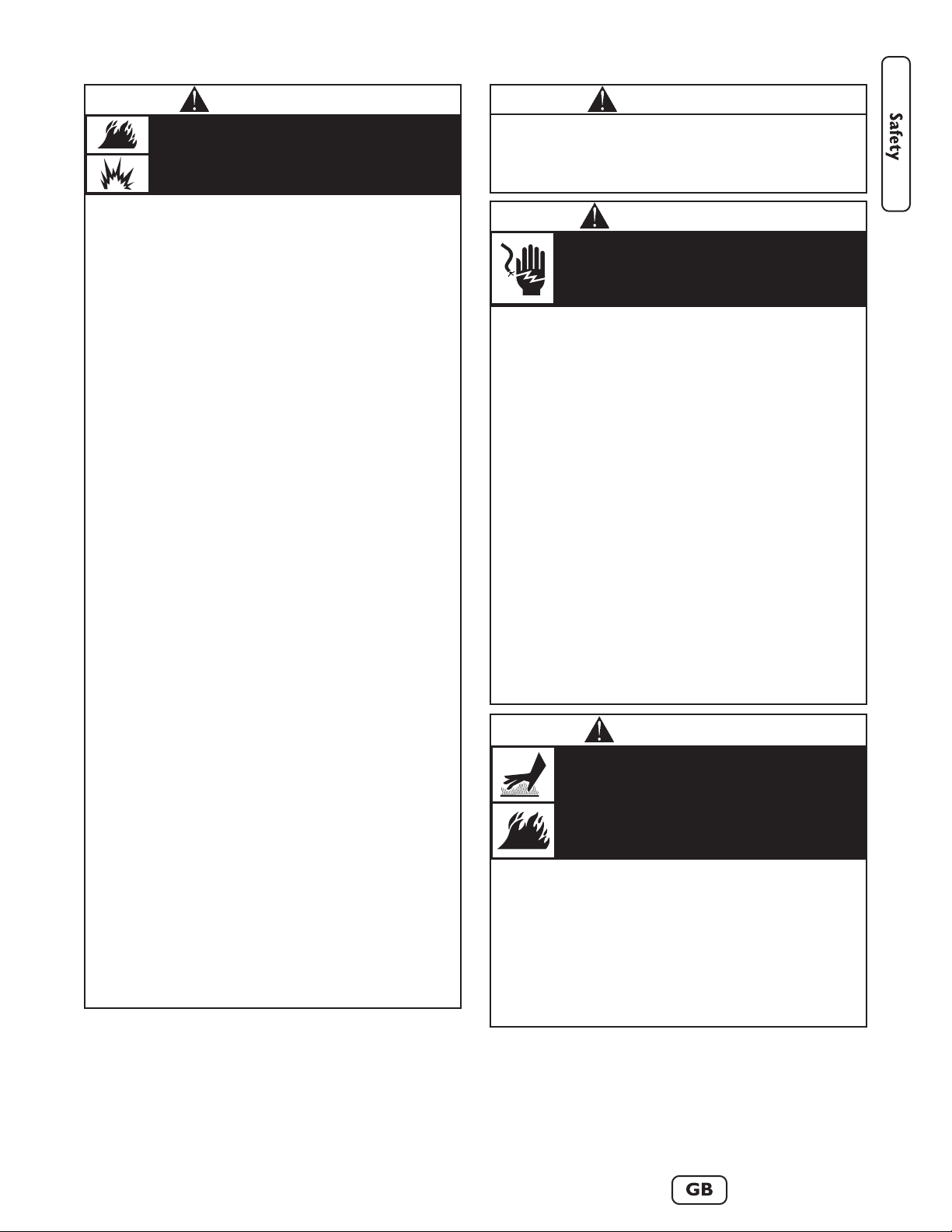
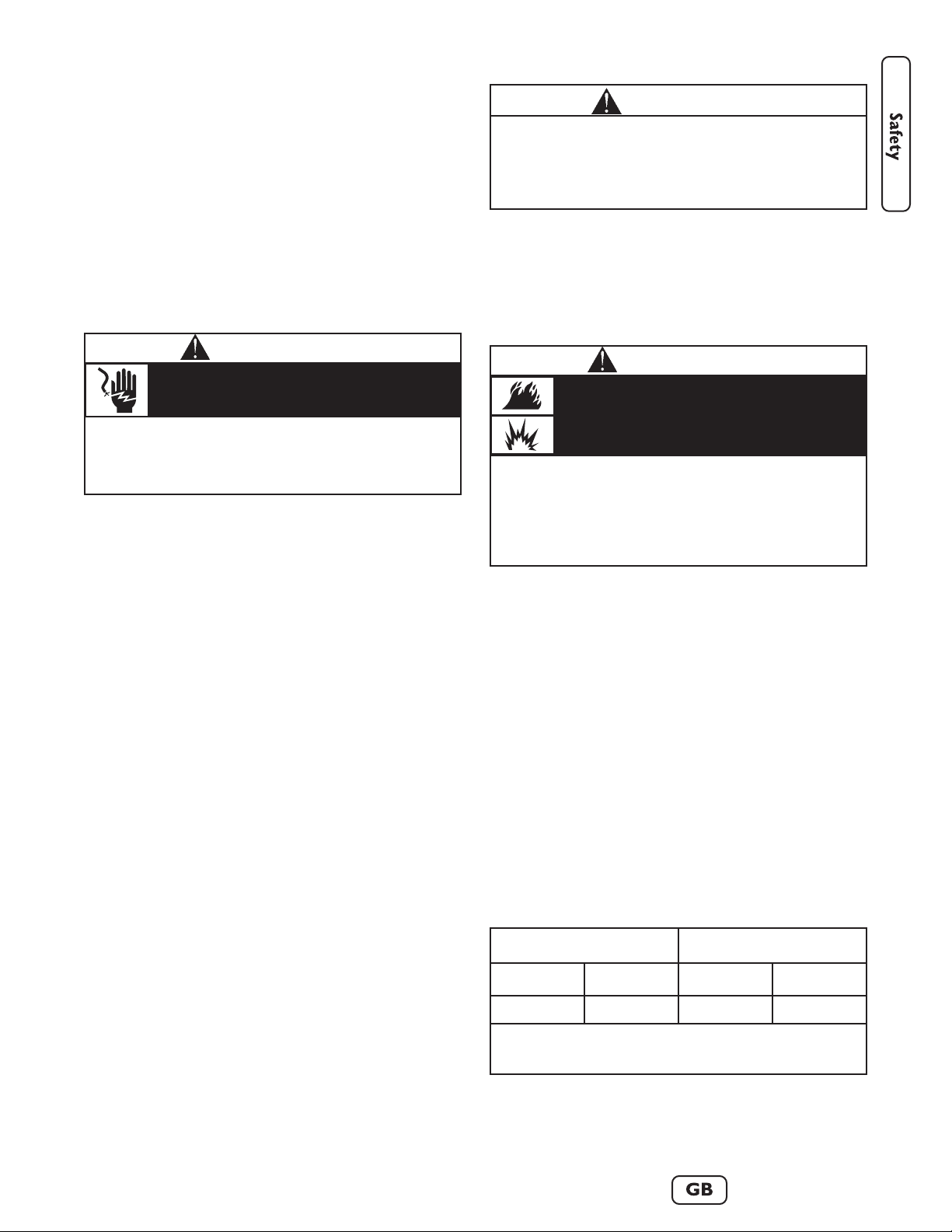
Hazard Symbols and Meanings
• Operate generator ONLY outdoors.
• Keep exhaust gas from entering a confined area through windows,
doors, ventilation intakes or other openings.
• DO NOT operate generator inside any building or enclosure
(even if doors or windows are open), including the generator
compartment of a recreational vehicle (RV).
Running generator gives off carbon monoxide,
an odorless, colorless, poison gas.
Breathing carbon monoxide can cause nausea,
fainting or death.
WARNING
The engine exhaust from this product contains
chemicals known to the State of California to
cause cancer, birth defects, or other reproductive
harm.
WARNING
Fire
Read
Manual
Explosive
Pressure
Chemical
Burns
Explosion
Toxic Fumes
Hot Surface
Electrical Shock
• DO NOT dispose of battery in a fire.
• DO NOT allow any open flame, spark, heat, or lit cigarette during
and for several minutes after charging a battery.
• DO NOT open or mutilate the battery.
• Wear protective goggles, rubber apron, and rubber gloves.
• Remove watches, rings, or other metal objects.
• Use tools with insulated handles.
Storage batteries give off explosive hydrogen
gas during recharging.
Slightest spark will ignite hydrogen and cause
explosion.
Battery electrolyte fluid contains acid and is
extremely acidic.
Contact with battery contents will cause severe
chemical burns.
A battery presents a risk of electrical shock and
high short circuit current.
DANGER
Using a generator indoors WILL KILL YOU
IN MINUTES.
Exhaust contains carbon monoxide, a
poison gas you cannot see or smell.
NEVER use in the home
or in partly enclosed
areas such as garages.
ONLY use outdoors and
far from open windows,
doors, and vents.
Page 5
3
• DO NOT touch hot surfaces and avoid hot exhaust gases.
• Allow equipment to cool before touching.
• Keep at least 5 ft. (152 cm) clearance on all sides of generator
including overhead.
• Code of Federal Regulation (CFR) Title 36 Parks, Forests, and
Public Property require equipment powered by an internal
combustion engine to have a spark arrester, maintained in
effective working order, complying to USDA Forest service
standard 5100-1C or later revision. In the State of California a
spark arrester is required under section 4442 of the California
Public resources code. Other states may have similar laws.
Running engines produce heat. Temperature of
muffler and nearby areas can reach or exceed
150°F (65°C).
Severe burns can occur on contact.
Exhaust heat/gases can ignite combustibles,
structures or damage LP fuel tank causing a fire.
WARNING
• When using generator for backup power, notify utility company.
Use approved transfer equipment to isolate generator from
electric utility.
• DO NOT use when under the influence of drugs or alcohol.
• Despite the safe design of the generator, operating this equipment
imprudently, neglecting its maintenance or being careless can
cause possible injury or death.
• Remain alert at all times while working on this equipment. Never
work on the equipment when you are physically or mentally
fatigued.
• DO NOT touch bare wires or receptacles.
• DO NOT use generator with electrical cords which are worn,
frayed, bare or otherwise damaged.
• DO NOT handle generator or electrical cords while standing in
water, while barefoot, or while hands or feet are wet.
• DO NOT allow unqualified persons or children to operate or
service generator.
• If you must work around a unit while it is operating, stand on an
insulated dry surface to reduce shock hazard.
• In case of an accident caused by electrical shock, immediately shut
down the source of electrical power and contact the local
authorities. Avoid direct contact with the victim.
• Before performing any maintenance on the generator, disconnect
the battery cable indicated by a NEGATIVE, NEG or (-) first.
When finished, reconnect that cable last.
• Remove the 15 Amp fuse BEFORE working on the equipment.
When finished, replace the 15 Amp fuse.
Generator produces hazardous voltage.
Failure to isolate generator from power utility
can result in death or injury to electric utility
workers due to backfeed of electrical energy.
WARNING
• Generator installation must comply with all applicable codes. To
check your local codes, see your local LP gas dealer or natural gas
company.
• Properly secure fuel tanks to LP fuel tank mounting tray as
described in “Assembly”.
• Before using the generator, fuel system hoses must be properly
purged and leak tested, especially after changing fuel tanks.
• No fuel leakage is permitted. NEVER check for leaks using a match
or open flame. Strong odors, colds, sinus congestion, etc. may
prevent the detection of gaseous fuel. Use caution and common
sense when testing for leaks (see “Leak Testing Fuel System”).
• After the generator is positioned for operation, inspect the fuel
system and connecting hoses for evidence of damage, excess wear
or deterioration periodically. If such defects are found, replace
components with manufacturer-supplied replacement parts ONLY.
The fuel hoses and regulator should be replaced every five years.
• When generator is not in use, manually close fuel shut off valve(s).
• DO NOT operate generator if smell of fuel is present.
• DO NOT smoke around generator. Wipe up any oil spills
immediately. Ensure that no combustible materials are left in the
generator compartment. Keep area near the generator clean and
free of debris.
• DO NOT supply unregulated gaseous fuel to generator. See
Product Specifications for required supply pressure.
• DO NOT allow fuel hose(s) to come in contact with hot surfaces.
• DO NOT store LP gas tank(s):
Indoors or in the vicinity of the generator
In a building, garage or any other enclosed area
Within the reach of children.
• LP gas tank must have:
A safety relief device having direct communication with the
cylinder vapor space
A listed over-filling prevention device (OPD)
DOT or CAN/CSA-B339 approval
A shut off valve, terminating in a fuel outlet compatible with
a Type 1 tank connector. No other tank connectors are
permitted for use with this generator.
A collar to protect the fuel shut off valve
• DO NOT insert any foreign objects into the tank valve outlet or
any of the fuel system components.
• LP tank supply system must be arranged for vapor withdrawal.
• Have LP gas tank filled to no more than 80% capacity by a
reputable propane gas dealer and visually inspected and
re-qualified at each filling.
• ALWAYS keep LP gas tanks in an upright position.
• ALWAYS handle LP gas tanks with care.
• The LP fuel tank is equipped with an internal thermal device that
will permanently shut off gas flow if the tank is subjected to
temperatures above 240° F (115° C). If this should happen, take
the LP fuel tank to your fuel supplier. The cause of the excessive
heat should be determined and corrected before using your
generator again.
• The normal flow of gas through the regulator and hose assembly
can create a humming noise. A low volume of noise is normal and
will not interfere with generator operation. If humming noise is
loud and excessive, the fuel supply system must be purged.
Propane and Natural Gas are extremely
flammable and explosive.
Fire or explosion can cause severe burns or
death.
WARNING
• This generator does not meet U. S. Coast Guard Regulation
33CFR-183 and should not be used on marine applications.
• Failure to use the appropriate U. S. Coast Guard approved
generator could result in death or serious injury and/or property
damage.
WARNING
Page 6
4
www.briggsandstratton.com
Equipment Description
Read this manual carefully and become
familiar with your generator. Know its
applications, its limitations and any hazards
involved.
The generator is an engine–driven, revolving field,
alternating current (AC) generator. It was designed to
supply electrical power for operating compatible electrical
lighting, appliances, tools and motor loads. The generator’s
revolving field is driven at about 3,600 rpm by a singlecylinder engine. The generator is operated on liquefied
propane (LP) gas. It can operate on natural gas (NG) fuel
only after conversion by a licensed professional gaseous
fuel technician.
This generator incorporates GFCI (Ground Fault Circuit
Interrupter) outlet protection and has its neutral bonded
to grounding fastener to comply to OSHA inspections on
job sites.
This generator will not function when connected to a
2 pole transfer switch since its service disconnect also has
a neutral bonded to ground. When both the generator
and the home or building’s service disconnect contains a
neutral bonded to ground, the generator’s GFCI will open
and no outlets will function.
A switching neutral transfer switch MUST be used if the
generator is connected to a building’s electrical system.
This product is intended for residential use as an allweather temporary source of electric power. It is capable
of supplying power to loads such as heating, refrigeration
systems, and communication systems. This product does
not qualify for emergency standby as defined by NFPA 70
(NEC). DO NOT use this generator for anything other
than it’s intended purpose.
Every effort has been made to ensure that the information
in this manual is both accurate and current. However, the
manufacturer reserves the right to change, alter or
otherwise improve the generator and this documentation
at any time without prior notice.
• DO NOT remove the neutral bond.
• Removing the neutral bond could result in death, bodily injury
and/or property damage.
GFCI will not function if neutral bond removed
DANGER
• See “Don’t Overload Generator”.
• Start generator and let engine stabilize before connecting electrical
loads.
• Connect electrical loads in OFF position, then turn ON for
operation.
• Turn electrical loads OFF and disconnect from generator before
stopping generator.
Exceeding generators wattage/amperage capacity can
damage generator and/or electrical devices connected
to it.
CAUTION
• Use generator only for intended uses.
• If you have questions about intended use, ask dealer or contact
Briggs and Stratton.
• Operate generator only on level surfaces.
• Adequate, unobstructed flow of cooling and ventilating air is
critical to correct generator operation.
• The access door and roof must be installed whenever the unit is
running.
• DO NOT expose generator to excessive moisture, dust, dirt, or
corrosive vapors.
• DO NOT start engine with air cleaner or air cleaner cover
removed.
• DO NOT insert any objects through cooling slots.
• DO NOT use the generator or any of its parts as a step. Stepping
on the unit can cause stress and break parts. This may result in
dangerous operating conditions from leaking exhaust gases, fuel
leakage, oil leakage, etc..
• If connected devices overheat, turn them off and disconnect them
from generator.
• Shut off generator if:
-electrical output is lost;
-equipment sparks, smokes, or emits flames;
-unit vibrates excessively.
Improper treatment of generator can damage it and
shorten its life.
CAUTION
• FOR RESIDENTIAL USE ONLY. DO NOT use this generator for
anything other than its intended purpose.
• DO NOT tamper with governed speed. Generator supplies
correct rated frequency and voltage when running at governed
speed.
• DO NOT modify generator in any way.
Excessively high operating speeds increase risk of injury
and damage to generator.
Excessively low speeds impose a heavy load.
CAUTION
When adjusting or making repairs to your
generator:
• Disconnect the spark plug wire from the spark plug and place the
wire where it cannot contact spark plug.
When testing for engine spark:
• Use approved spark plug tester.
• DO NOT check for spark with spark plug removed.
Unintentional sparking can result in fire or
electric shock.
WARNING
Page 7
5
Ground Fault Protection
The generator’s receptacles are equipped with Ground
Fault Circuit Interrupter (GFCI) protection. This GFCI
device meets applicable federal, state and local codes.
The GFCI protects against electrical shock that may be
caused if your body becomes a path in which electricity
travels to reach the ground. This could happen if you
touch a “Live” appliance or wire, or are touching plumbing
or other materials that connect to the ground.
When protected by a GFCI device, one may still feel a
shock, but the GFCI should cut current off quickly enough
so that a person in normal health should not suffer any
serious electrical injury.
Connections
to a Building’s Electrical
System
Connections from this generator to a building’s electrical
system must be made through a switching neutral transfer
switch installed by a qualified electrician. The connection
must isolate the generator power from utility power, and
must comply with all applicable laws and electrical codes.
IMPORTANT: A switching neutral transfer switch MUST
be used when switching between utility and generator power.
Customer’s Responsibilities
• If considering installation with a transfer swith, read
and follow the instructions given in this manual.
• Follow a regular schedule in maintaining, caring for
and using your generator, as specified in this manual.
• ALWAYS disconnect and store indoors the cord used
to connect generator and inlet connection box when
generator is not in use.
To help you make informed choices and communicate
effectively with your installation contractor(s),
Read and understand the Assembly section of
this manual before starting your generator
installation.
You can arrange for proper installation by contacting the
store at which you purchased your generator, your Briggs
& Stratton dealer, a licensed professional electrician or
your utility power provider.
The generator warranty is VOID if permanent fuel
connections to the generator are installed by
anyone other than a licensed gaseous fuel
professional.
The generator warranty is VOID if permanent
electrical connections to the generator are made.
The Gaseous Fuel System
The generator unit has been factory set to run on
liquefied petroleum gas. If the generator is to run on
natural gas, the engine will need to be reconfigured using
the supplied NG Conversion kit. Contact a licensed
professional gaseous fuel technician to install this kit.
The generator engine is fitted with a fuel mixer system
that meets the specifications of the California Air
Resources Board for “tamper-proof” dual fuel systems.
The unit will run on natural gas or liquefied propane
vapor.
• Use clean, dry fuel, free of moisture or any particulate
material. Using fuels outside the following
recommended values may cause performance
problems:
• Commercial grade HD5 LPG is recommended minimum fuel energy of 2500 BTU’s/ft
3
with maximum
propylene content of 5% and butane and heavier gas
content of 2.5% and minimum propane content of 90%.
• See “Specifications” for required fuel supply pressure.
Fuel Consumption
See the following table for fuel supply requirements at half
and full load for both natural gas and LP vapor.
• Contact with the hot and neutral conductor at the same time can
cause electrical shock or burn, even if the circuit is GFCI
protected.
• Before using the GFCI receptacle, ALWAYS push the test button
to insure it works.
Generator produces hazardous voltage/current.
WARNING
Only qualified electricians and gaseous fuel
technicians should attempt fuel conversion or
permanent connection of this generator. Each
installation must strictly comply with applicable
codes, standards and regulations.
WARNING
• LP gas is heavier than air and will settle in low areas.
• Natural gas is lighter than air and will collect in high areas.
• The slightest spark can ignite these fuels and cause an explosion.
• IF YOU SMELL GAS - Shut off gas to the generator at the LP
cylinder(s)/source.
• If odor continues, leave the area and immediately call your gas
supplier or fire department.
Propane and Natural Gas are extremely
flammable and explosive.
Fire or explosion can cause severe burns or
death.
WARNING
Natural Gas* LP Vapor**
1/2 Load Full Load 1/2 Load Full Load
80 137 33 56
* = Natural Gas is in cubic feet per hour
** = LP Vapor is in cubic feet per hour
Fuel Supply Requirements
Page 8
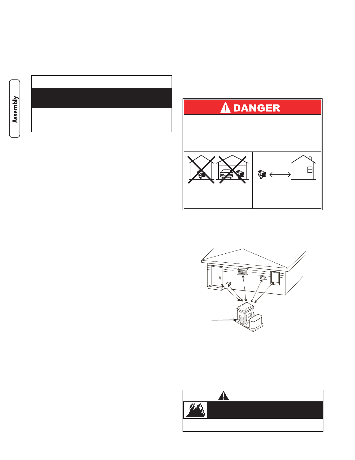
Generator Location
Consider these factors when determining the proper
generator operating location:
• Install the unit outdoors on a flat, level surface with
provisions for adequate ventilation. This will allow for
dispersion of deadly exhaust gas. DO NOT install
generator where exhaust gas could accumulate and
enter inside or be drawn into a potentially occupied
building areas.
Ensure exhaust gas is kept away from any windows,
doors, ventilation intakes or other openings that can
allow exhaust gas to collect in a confined area
(Figure 1). Prevailing winds and air currents should be
taken into consideration when positioning generator.
• The unit must have at least 5 ft. (152 cm) of clearance
on all sides of the enclosure and LP tank housing pad,
including overhead. This will reduce the risk of
exhaust heat or exhaust gases igniting nearby
combustible materials and will provide for adequate
cooling and generator maintenance.
6
www.briggsandstratton.com
Assembly/Installation
Your generator is ready for use after you assemble the LP
fuel tank housing pad components, make proper fuel
connections, and verify that engine oil is at the proper
level.
If you have any problems with the assembly of your
generator, please call the generator helpline at
1-800-743-4115. If calling for assistance, please have the
model, revision, and serial number from the data tag
available. See “Generator Controls and Features” for data
tag location.
Shipment Contents
The generator is supplied with:
• Generator pre-attached to mounting pad
• LP fuel tank housing tray assembly pre-attached to
mounting pad
• Fuel hose and regulator assembly pre-attached to
generator
• LP fuel tank all-weather cover
• Bag containing LP fuel tank attachment hardware
• Operator’s manual
• Battery
• Oil drain tray
• Touch-up paint
• One spare 15A fuse
• NG conversion kit
You must purchase two filled 20 pound DOT LP fuel tanks
that are equipped with a listed over-filling prevention
device (OPD).
Lifting the Generator
CAUTION The generator weighs more than
280 pounds (130 kg). Proper tools, equipment and
qualified personnel should be used in all phases of
handling and moving the generator. Each full LP
tank will weigh more than 20 pounds (9 kg).
CAUTION DO NOT lift unit by roof as damage to
generator will occur.
Lifting pockets are provided at each corner between the
base of the generator and its mounting pad. See
“Generator Controls and Features” for locations. Retouch
any chipped paint with supplied touch-up paint.
• Keep at least 5 ft. (152 cm) clearance on all sides of generator
including overhead.
Exhaust heat/gases can ignite combustibles,
structures or damage LP fuel tank causing a fire.
WARNING
CAUTION
• Refer to Maintenance for oil fill information.
• Damage to equipment resulting from failure to follow this
instruction will void warranty.
Any attempt to crank or start the engine without
verifying it has been properly serviced with the
recommended oil will result in equipment failure.
Figure 1 — Generator Clearances
A - Engine Exhaust Opening
A
Using a generator indoors WILL KILL YOU
IN MINUTES.
Exhaust contains carbon monoxide, a
poison gas you cannot see or smell.
NEVER use in the home
or in partly enclosed
areas such as garages.
ONLY use outdoors and
far from open windows,
doors, and vents.
Page 9
7
• Install the unit in a location where sump pump
discharge, rain gutter down spouts, roof run-off,
landscape irrigation, or water sprinklers will not flood
the unit or spray the enclosure and enter any air inlet
or outlet openings.
• Install the unit where the location of any services such
as phone, electrical, fuel, air conditioning, irrigation,
including covered, concealed and underground
services will not be affected or obstructed.
• Install the unit where air inlet and outlet openings will
not become obstructed by leaves, grass, snow, etc. If
prevailing winds will cause blowing or drifting, you
may need to construct a windbreak to protect the
unit.
The generator is shipped already attached to its mounting
pad. Unless mandated by local code, a concrete slab is not
required.
If mandated by local code, construct a concrete slab at
least 3 inches thick and 6 inches longer and wider than the
combined generator and LP tank pad footprint. Attach
pads to slab with 1/4” diameter (minimum) masonry
anchor bolts.
Attach LP Fuel Tank Housing Pad Parts
Required Tools
You will need either of the following tools to attach the
LP fuel tank housing pad to the generator pad:
• 1/2 inch (13 mm) socket and ratchet OR
• 1/2 inch (13 mm) open end wrench
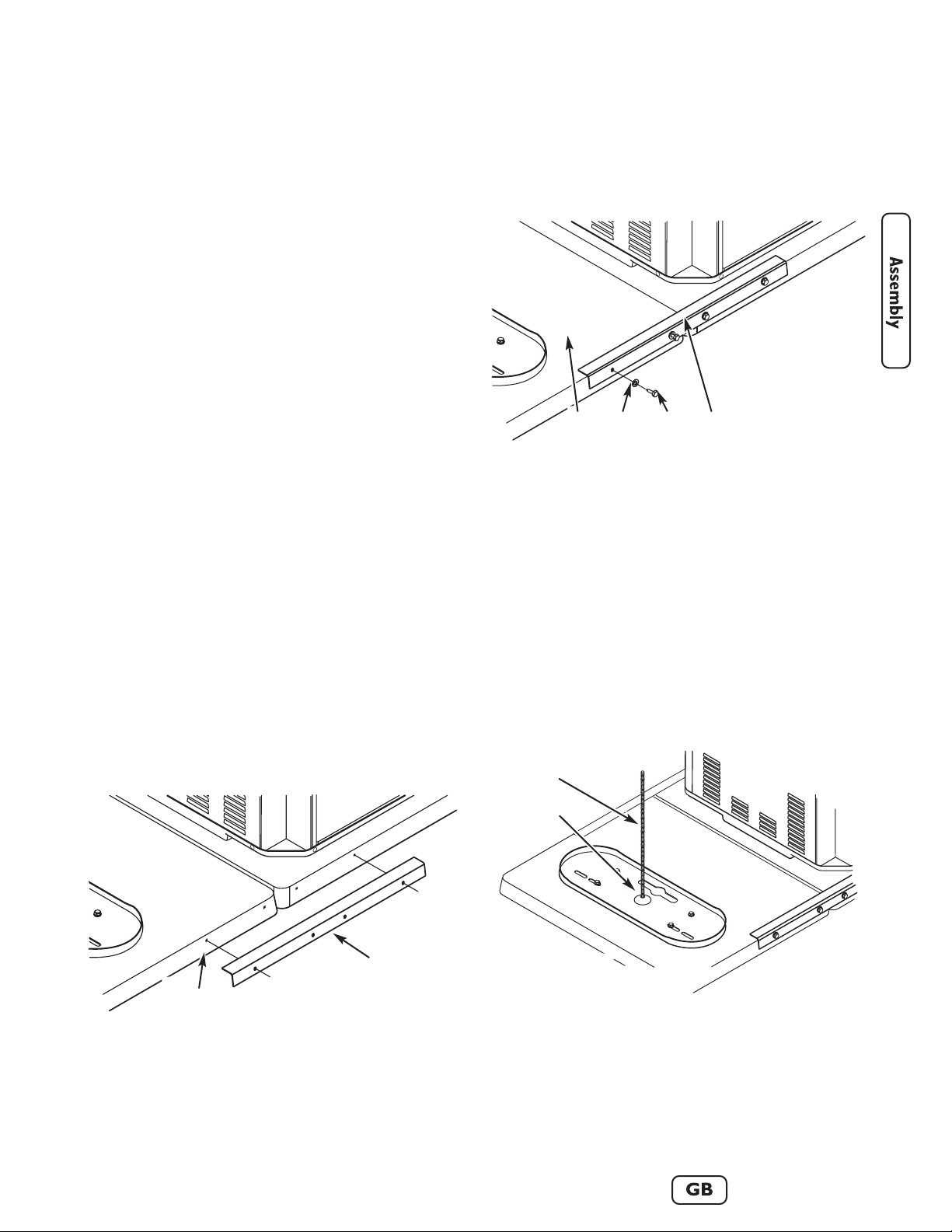
Attach Mounting Pads Together
1. Place LP tank housing pad (with pre-attached LP fuel
tank tray) on the ground next to the side of the
generator where the fuel hose(s) and regulator are
attached.
Confirm that the pre-drilled holes on both mounting
pads are adjacent to each other (see Figure 2).
2. Lay one 20 inch (50 cm) angle bracket across both
mounting pads, aligning the bracket holes with the
pre-drilled pad holes, as shown in Figure 2.
3, Pass one 5/16” X 1” lag bolt through one 5/16” flat
washer, then through one hole on the angle bracket.
Finger tighten lag bolt into mounting pad hole (see
Figure 3).
4. Repeat Step 3 three more times, placing a lag
bolt/washer in each angle bracket hole.
5. Tighten each lag bolt until snug using specified tool.
DO NOT over-tighten as threads could strip.
6. Repeat Steps 2 through 5 to attach the second angle
bracket to the opposite ends of the mounting pads.
Attach Tank Hold-Down Rod
Insert either end of the supplied threaded rod into the LP
fuel tank tray location shown in Figure 4. Hand tighten
rod.
Figure 2 — Mounting Pad and Angle Bracket Holes
A - Mounting Pad Holes
B - Angle Bracket
B
A
Figure 3 — Start Lag Bolts into Mounting Pad Holes
A - Mounting Pad
B - Flat Washer
C - Lag Bolt
D - Angle Bracket
C
DBA
Figure 4 — Attach Tank Hold-Down Rod to LP Tank Tray
A - Hold-Down Rod
B - LP Fuel Tank Tray
A
B
Page 10
8
www.briggsandstratton.com
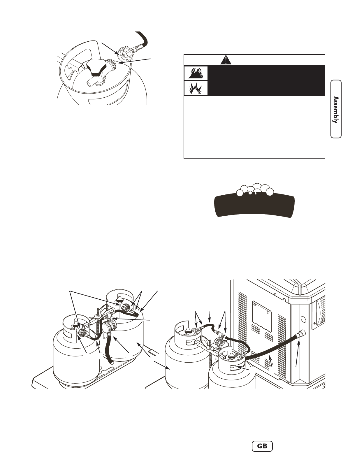
LP Fuel Tank Installation
IMPORTANT: To ensure optimal performance,
use two (2) LP fuel tanks during operation.
This section describes the proper method of installing and
leak testing the generator’s LP fuel tanks. This system is
supplied with an LP fuel tank cover. Always cover the LP
fuel tanks whenever they are connected to the generator.
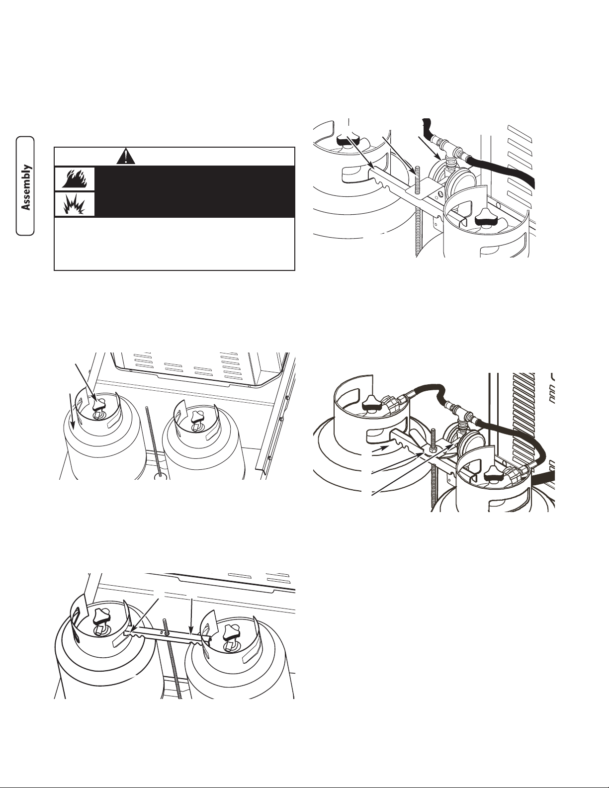
To Install LP Fuel Tanks:
1. Confirm both LP fuel tank shut off valves are closed
(turned fully CLOCKWISE).
2. Place each LP tank into the LP tank tray with it’s fuel
valve pointing towards the generator (see Figure 5).
3. Slide the LP fuel tank hold-down bracket onto the
threaded rod. Position the bracket so that its notches
are aligned with both LP fuel tank collar holes, as
shown in Figure 6.
It may be necessary to “wiggle” the LP fuel tanks and
the bracket to obtain proper alignment.
4. Slide the fuel hose/regulator assembly over the
threaded rod so that it faces the generator and rests
on the hold-down bracket (see Figure 7).
5. Thread the wing nut CLOCKWISE onto the threaded
rod. Hand tighten wing nut against fuel hose/regulator
assembly, ensuring hold-down bracket notches remain
engaged with LP fuel tank collars and LP fuel tanks are
held firmly. See Figure 8.
6. Remove protective covers from both LP fuel tank shut
off valve connectors. DO NOT discard protective
covers - they should be installed any time the LP fuel
tank is disconnected from the generator.
7. Insert the nipple of the left connection device (as you
face the generator and LP fuel tanks) into the left LP
fuel tank valve outlet (see Figure 9). Ensure it is fully
inserted.
• The slightest spark can ignite this fuel and cause an explosion.
• IF YOU SMELL GAS - Shut off gas to the generator at the LP fuel
tank(s).
• If odor continues, leave the area and immediately call your gas
supplier or fire department.
Propane Gas is extremely flammable and
explosive.
Fire or explosion can cause severe burns or
death.
WARNING
Figure 5 — Proper Position for LP Fuel Tanks
A - LP Fuel Tank Shut Off Valve Connector
B - LP Fuel Tank
B
A
Figure 6 — Properly-Aligned Hold-Down Bracket
A - Bracket Notch over Fuel Tank Collar
B - Hold-Down Bracket
BA
Figure 7 — Fuel Hose/Regulator Assembly Placement
A - Hold-Down Bracket
B - Threaded Rod
C - Fuel Hose/Regulator Assembly
A B C
Figure 8 — Properly-Secured LP Fuel Tanks
A - LP Fuel Tank
B - Wing Nut
C - Fuel Hose/Regulator Assembly
A
B
C
Page 11
3. Using a sponge, rag or small non-metallic brush, apply
the soap water mixture at each of the locations
shown in Figure 10 below.
4. Check each location shown in Figure 10 for growing
bubbles, which indicates a fuel leak. Bubbles will look
something like this:
5. Close both LP fuel tank shut off valves (turn fully
CLOCKWISE).
6. Press and hold control panel’s START/RUN/STOP
switch in START position for 5 seconds to release gas
pressure in hoses. See “Control Panel Controls and
Features”.
7. Tighten or replace any leaking connections.
9
8. Turn the large coupling nut CLOCKWISE and hand
tighten to a full stop.
DO NOT cross thread the connection.
DO NOT use thread sealant.
DO NOT over-tighten the coupling nut.
DO NOT use tools to tighten the connection.
NOTE: If you are unable to make the connection, repeat
Step 7 or contact an LP fuel professional.
9. Repeat Steps 7 and 8 to attach the right LP fuel tank.
10. Confirm that each fuel hose does not have kinks and
that it does not touch sharp edges or surfaces that
may become hot during generator operation.
11. Perform a complete fuel leak test, using the
instructions given in “Leak Testing Fuel System”.
Leak Testing Fuel System
1. Create a mixture of 50% water and 50% liquid
dishwashing soap.
2. Turn ON the fuel supply by turning both LP fuel tank
shut off valves one full turn COUNTERCLOCKWISE.
Figure 10 — Leak Test Locations
A - LP Fuel Tank Welds
B - LP Fuel Tank Shut Off Valves at Cylinder
Connections
C - Both Coupling Nuts to LP Fuel Tank Shut Off Valve
Connections
D - Back Sides of Coupling Nuts and Hose Connection
Joints
E - Brass T-Valve Connections (all joints)
F - Regulator Connection to Fuel Hose
G - The Full Length of all Fuel Hoses
H - Fuel Hose Connection to Generator (all joints)
A
D
B G H
G
E
F
E
C D
G
B G
• DO NOT smoke or permit ignition sources in the area while
conducting a leak test.
• Perform leak test OUTDOORS only in a well ventilated area.
• DO NOT perform a leak test with a match or open flame.
• DO NOT perform a leak test while the generator is in use.
• ALWAYS perform a leak test when first using the generator.
• ALWAYS perform a leak test every time an LP fuel tank or any
fuel system component is changed.
• ALWAYS perform a leak test whenever the generator is moved.
• Perform a leak test at least once per year or if your generator has
not been used for more than 60 days.
Propane Gas is extremely flammable and
explosive.
Fire or explosion can cause severe burns or
death.
WARNING
Figure 9 — Proper Connection Device Alignment
A - Fuel Hose Connector Nipple
B - LP Fuel Tank Shut Off Valve Connector
B
A
Page 12
10
www.briggsandstratton.com
8. Repeat Steps 2 through 7 until no leaks are detected.
DO NOT use the generator if leaks cannot be
stopped. Contact a qualified LP fuel professional for
assistance.
9, Turn OFF both LP fuel tank shut off valves until you
are ready to use the generator.
10. Wash off soapy residue with clean cold water and
towel dry.
11. Wait five minutes to allow all gas to evacuate the area
before starting the generator.
NOTE: The leak test must be performed in an area that
has adequate lighting in order to see if bubbles are
developing. DO NOT use a flashlight to check for bubbles.
To Remove LP Fuel Tank(s)
1. Confirm the LP fuel tank shut off valve is closed
(turned fully CLOCKWISE).
2. Disconnect the fuel hose from the LP tank by turning
the large coupling nut COUNTERCLOCKWISE by
hand (see Figure 9).
3. Install the protective cover over the LP fuel tank shut
off valve outlet.
4. Remove wing nut from threaded rod by turning it
COUNTERCLOCKWISE. Lift and remove the fuel
hose/regulator assembly from the threaded rod. See
Figures 7 and 8.
5. Lift and remove the LP tank hold-down bracket from
threaded rod (see Figure 6). It may be necessary to
wiggle the LP fuel tanks to release the hold-down
bracket.
6. Carefully lift the LP fuel tank off the LP fuel tank tray.
Verify Engine Oil Level
The generator engine is shipped from the factory filled
with synthetic oil (API SJ/CF 5W-30W). This allows for
generator operation in the widest range of temperature
and climate conditions. Before starting the engine, check
oil level and ensure that engine is serviced as described in
“Maintenance”.
NOTE: The use of synthetic oil does not alter the
required oil change intervals described in the
Maintenance section.
Removable Roof and Access Door
The generator enclosure includes a removable roof and
battery access door.
To Remove Roof:
There are two screws on each side of the roof located in
the half-moon roof slots. Remove the four screws and lift
roof off.
To Remove Battery Access Door:
1. Disconnect any loads connected to the generator.
2. Remove roof as described above.
3. Remove screw at top of access door.
4. Pull access door outward (away) from unit while
pulling door upward and out of base.
Door will come free of generator enclosure.
To Install Battery Access Door and Roof:
1. Guide bottom of access door into base.
2. Push access door in until it is flush with sides.
3. Replace door screw.
4. Replace roof and four roof screws.
Battery Connection
The generator is supplied with a sealed, lead-acid
rechargeable 12 Volt DC, AGM type, 33 Amp-Hour,
battery. The battery cables are connected at the factory.
The battery will lose some charge in shipping and prior to
generator installation. If battery voltage is too low to start
the engine, charge the battery, as described in
“Maintenance”.
If the battery fails to take a charge, it must be replaced
ONLY with the same type of 12 Volt DC, AGM type,
33 Amp-Hour battery. DO NOT replace with liquid
electrolyte lead-acid type battery.
CAUTION
• Refer to Maintenance for oil fill information.
• Damage to equipment resulting from failure to follow this
instruction will void warranty.
Any attempt to crank or start the engine without
verifying it has been properly serviced with the
recommended oil will result in equipment failure.
• DO NOT dispose of battery in a fire.
• DO NOT allow any open flame, spark, heat, or lit cigarette during
and for several minutes after charging a battery.
• DO NOT open or mutilate the battery.
• Wear protective goggles, rubber apron, and rubber gloves.
• Remove watches, rings, or other metal objects.
• Use tools with insulated handles.
Storage batteries give off explosive hydrogen
gas during recharging.
Slightest spark will ignite hydrogen and cause
explosion.
Battery electrolyte fluid contains acid and is
extremely acidic.
Contact with battery contents will cause severe
chemical burns.
A battery presents a risk of electrical shock and
high short circuit current.
DANGER
Page 13
11
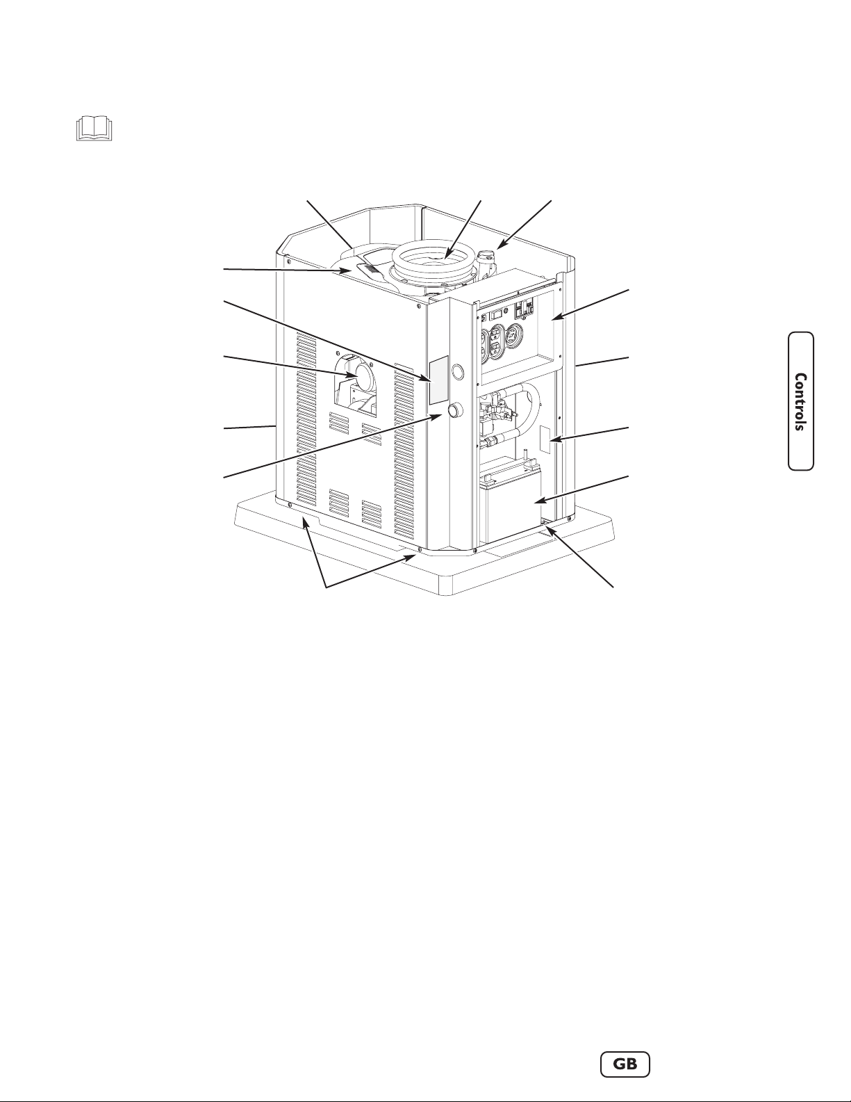
Generator Controls and Features
Read this Operator’s Manual and safety rules before operating your generator.
Compare the illustrations with your generator, to familiarize yourself with the locations of various controls and
adjustments. Save this manual for future reference.
Generator is shown with roof, oil filter access door, battery access door and control panel cover removed.
See Figures 5 through 8, earlier, for important LP fuel tank component views.
N
A
M
G
L
KH
CB
E
D
F
A - Engine Model Number Identification — (stamped
on top of valve cover) Identifies engine model and type.
B - Rotating Screen — Prevents large debris from
entering engine cooling airflow stream.
C - Oil Fill Cap/Dipstick — Check and fill engine with
recommended oil here.
D - Control Panel — Used for various operation and
maintenance functions. See “Control Panel Controls and
Features” on next page.
E - Oil Drain Hose — Provided to facilitate oil changing.
F - Unit Data Decal — Displays model, revision and
serial numbers.
G - Battery — 12 Volt DC, 33 Amp-Hour, sealed battery
provides power to start engine. Battery receives trickle
charge whenever generator is running.
H - Equipment Grounding Terminal — Connect
generator to earth ground here.
K - Lifting Pockets — Provided at each lower corner
for lifting generator and attached pad.
L - Fuel Inlet — Fuel supply components are attached to
generator here.
M - Exhaust Port — High-performance muffler lowers
engine noise to comply with most residential codes.
Includes approved spark arrester.
N - Oil Filter — Filters engine oil to prolong generator
life.
P - Hazard/Start/Stop Instructions — Observe these
warnings and procedures when operating generator.
R - Air Cleaner — Uses a dry type filter element and
foam precleaner to
protect engine by filtering dust and
debris out of intake air.
R
P
Page 14
12
www.briggsandstratton.com
GFCI
MAIN BREAKER
PUSH
TO
RESET
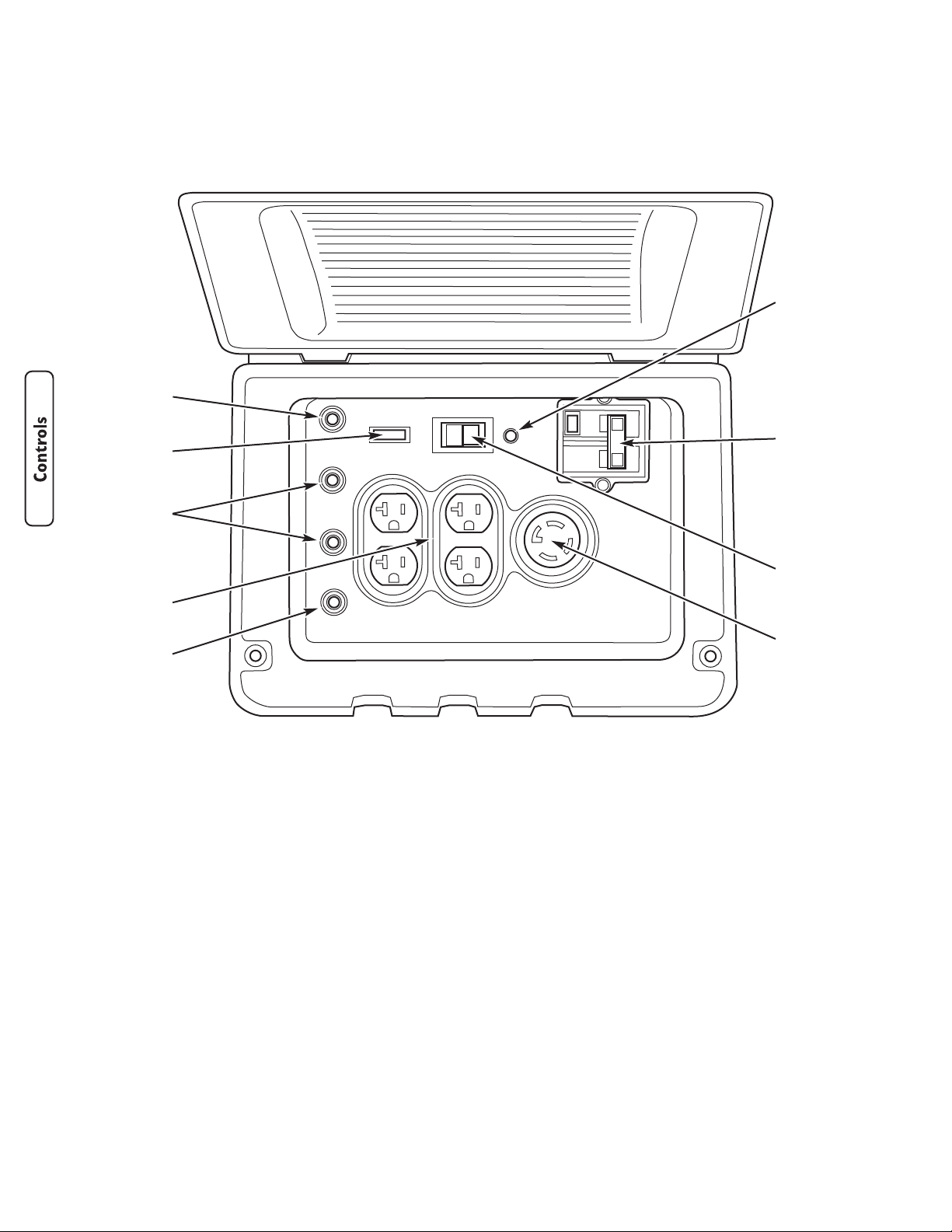
Control Panel Controls and Features
Compare this illustration with your generator’s Control Panel, to familiarize yourself with the locations of the receptacles,
controls and circuit breakers:
A - LED Light — Generator is producing voltage when
illuminated.
B - Ground Fault Circuit Interrupter/Breaker —
Protects the generator from over-current conditions
electrical faults to ground and must be in the “ON”
position to supply power to all of the control panel
receptacles.
C - START/RUN/STOP Switch — This three-position
switch is used as follows:
•“START” position starts the generator. Press and
hold to start generator.
•“RUN” position is switch position while generator is
running.
•“STOP” position turns off the generator. Press and
hold until engine stops.
D - 120/240V 30 Amp Locking Receptacle —
Supplies the total generator output power and is
GFCI protected.
E - Push-to-Reset Circuit Breakers — Protects the
generator from current overload at receptacle.
F - 120 Volt 20 Amp Receptacles — Each receptacle
can supply a maximum of 20 amperes of power. The
120 Volt receptacles are GFCI protected. Total load
on all four receptacles cannot exceed 7000 watts.
G - 15 Amp Fuse — Protects the generator DC control
circuits. If the fuse has melted open or was removed,
the engine cannot crank or start. Replace the fuse
using only an identical ATO-type 15A fuse, available
from most automotive parts stores.
120/240V 30A
G
C
A
E
E
E
F
D
B
PUSH
TO
RESET
120V 20A
ALL RECEPTACLES GFCI-PROTECTED
120V 20A
15A FUSE
START/RUN/STOP
Page 15
13
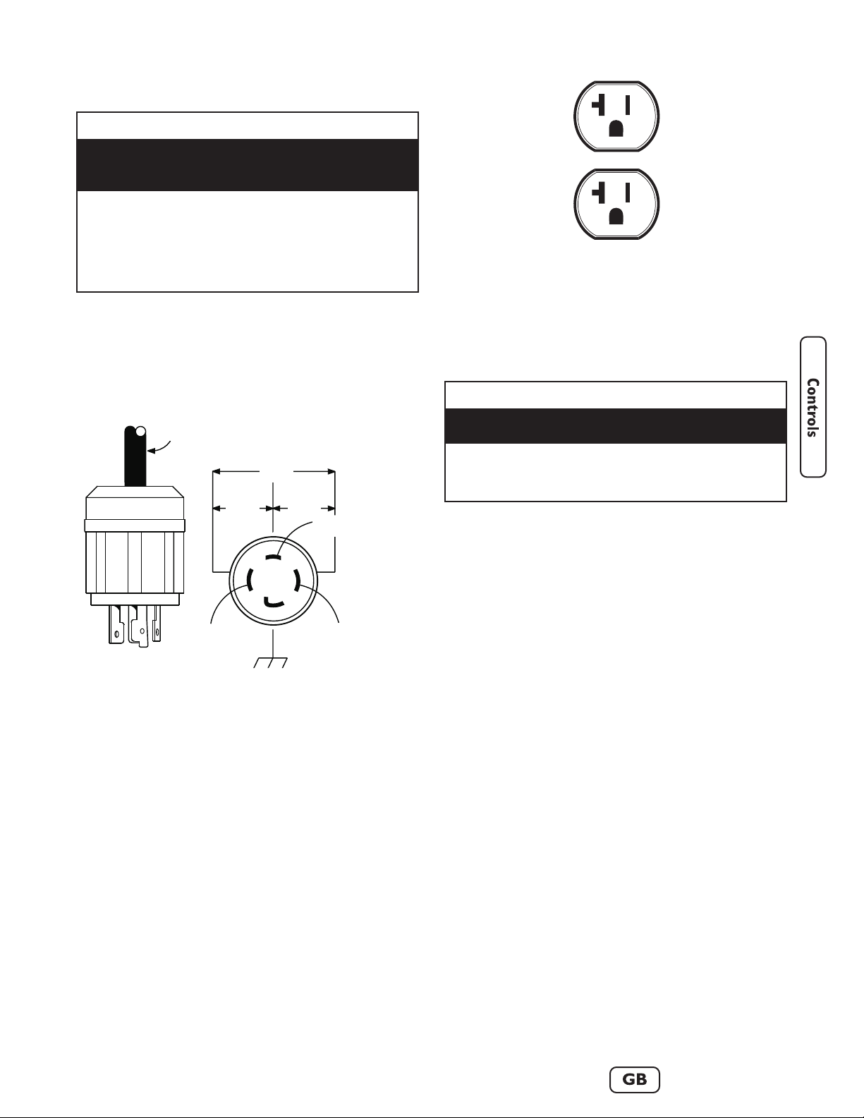
Receptacles
120/240 Volt AC, 30 Amp, Locking
Receptacle
This receptacle (Figure 11) supplies the entire generator
output and is protected against overload by a double-pole
GFCI circuit breaker.
Use a NEMA L14–30 plug with this receptacle. Connect a
4–wire cord set rated for 250 Volt AC loads at 30 Amps
(or greater). You can use the same 4–wire cord if you
plan to run a 120 Volt load. Inspect cord set(s) before
each use. Store cord set(s) indoors.
When operating on LP fuel, this receptacle powers
120/240 Volt AC, 60 Hz, single phase loads requiring up
to 7,000 watts of power (7.0 kW) at 29.16 Amps for
240 Volts or two independent 120 Volt loads at
29.16 Amps each.
120 Volt AC, 20 Amp, Duplex Receptacles
Each individual duplex receptacle (Figure 12) is protected
against overload by a push-to-reset circuit breaker. All
four receptacles are also protected by a double-pole GFCI
circuit breaker.
Use each receptacle to operate 120 Volt AC,
single–phase, 60 Hz electrical loads requiring up to
2,400 watts (2.4 kW) at 20 Amps of current when
operating on LP fuel. Use cord sets that are rated for
125 Volt AC loads at 20 Amps (or greater). Inspect cord
set(s) before each use.
NOTE: Follow all safety precautions when connecting any
extension cord or device to the generator.
Equipment Ground
The generator is equipped with an equipment grounding
terminal that connects the generator frame components
to the ground terminals on the AC output receptacles.
Ground the generator per applicable codes, standards, and
regulations.
The equipment ground is connected to the AC neutral
wire and the neutral is bonded to the generator frame.
The equipment grounding terminal is shown on
“Generator Controls and Features”.
Special Requirements
There may be Federal or State Occupational Safety and
Health Administration (OSHA) regulations, local codes, or
ordinances that apply to the intended use of the
generator. Please consult a qualified electrician, electrical
inspector, or the local agency having jurisdiction.
• In some areas, generators are required to be
registered with local utility companies.
• If the generator is used at a construction site, there
may be additional regulations which must be
observed.
• NEVER attempt to power a device requiring more amperage than
generator or receptacle can supply.
• DO NOT overload the generator. See “Don’t Overload
Generator”.
Receptacles may be marked with rating value greater
than generator output capacity.
CAUTION
• See “Don’t Overload Generator”.
• Start generator and let engine stabilize before connecting electrical
loads.
• Connect electrical loads in OFF position, then turn ON for
operation.
• Turn electrical loads OFF and disconnect from generator before
stopping generator.
Exceeding generators wattage/amperage capacity can
damage generator and/or electrical devices connected
to it.
CAUTION
Figure 11 — 120/240 Volt AC, 30 Amp Receptacle
4-Wire Cord Set
240V
120V
120V
W (Neutral)
X (Hot)
Y (Hot)
NEMA L14-30
Ground (Green)
Figure 12 — 120 Volt, 20 Amp Duplex Receptacle
Page 16
14
www.briggsandstratton.com
Operating Your Generator
Starting the Engine
Use the following start instructions:
1. Make sure unit is on a flat, level surface.
IMPORTANT: Failure to start and operate unit on a
level surface will cause the unit not to start or shut down
during operation.
2. Open control panel cover using standard screwdriver.
3. Disconnect all load(s) to generator.
4. Open LP tank fuel shut off valve(s).
5. Confirm 15 Amp fuse is installed in control panel.
6. Push and hold START/RUN/STOP switch in START
position until engine starts and control panel LED is
ON.
IMPORTANT: If you release the switch from the
START position before red LED comes on, the generator
will shut down.
NOTE: DO NOT crank engine for more than
15 seconds, then pause for 15 seconds to reduce heat in
starter. Repeat start process until engine starts.
NOTE: When starting generator, air may be present in
the fuel line(s), especially after changing fuel tanks. It may
take several starting cycles to purge that air before the
engine will start.
Connecting Electrical Loads
1. Let engine run for two minutes after starting.
2. Open control panel cover and confirm generator’s
main circuit breaker is in the ON (closed) position.
See “Control Panel Controls and Features”.
3. Plug in, then turn on the desired 120 and/or 240 Volt
AC, single phase, 60 Hz electrical loads.
3. Close and latch control panel cover.
IMPORTANT:
• DO NOT connect 240 Volt loads to the 120 Volt
duplex receptacles.
• DO NOT connect 3–phase loads to the generator.
• DO NOT connect 50 Hz loads to the generator.
• DO NOT OVERLOAD THE GENERATOR. See
“Don’t Overload Generator”.
Stopping the Engine
1. Open control panel cover using standard screwdriver.
2. Turn OFF all electrical loads. Disconnect them from
control panel receptacles.
Never start or stop engine with electrical devices
plugged in and turned on.
3. Let engine run for two minutes with no loads to
stabilize internal temperatures of engine and
generator.
4. Push and hold START/RUN/STOP switch in STOP
position until LED turns off and engine stops.
5. Close manual fuel shut off valve(s).
6. Close and latch control panel cover.
These steps should be performed after the generator has been
assembled, stored, moved, cleaned, or repaired. DO NOT operate this
generator until you have read and understand ALL of the warnings and
instructions in this operator’s manual.
• Insure that the generator is properly assembled.
• Inspect the LP fuel supply hoses for burns, chaffing, kinks, and
proper routing before each use. Hoses should be kept at least
3 inches (8 cm) away from hot surfaces.
• Leak test all LP fuel connections and and hoses. See “Leak Testing
Fuel System”.
• Position your generator on level ground in a well ventilated
location, 5 feet (152 cm) away from combustible materials and
buildings, including overhead. DO NOT use generator on wooden
decks or other surfaces that could burn.
Propane Gas is extremely flammable and
explosive.
Fire or explosion can cause severe burns or
death.
WARNING
• DO NOT touch hot surfaces and avoid hot exhaust gases.
• Allow equipment to cool before touching.
• Keep at least 5 ft. (152 cm) clearance on all sides of generator
including overhead.
Running engines produce heat. Temperature of
muffler and nearby areas can reach or exceed
150°F (65°C).
Severe burns can occur on contact.
Exhaust heat/gases can ignite combustibles,
structures or damage LP fuel tank causing a fire.
WARNING
Page 17
15
Ground Fault Protection
This unit is equipped with a Ground Fault Circuit
Interrupter (GFCI). This device meets applicable federal,
state and local codes.
Test GFCI Circuit Breaker
Test your GFCI circuit breaker (see “Control Panel
Controls and Features” for location) every month, as
follows:
1. While generator is running and control panel cover
open, push white “Test” button. The circuit breaker
should trip (handle will move to approximate center
position), which will disconnect power to outlets.
2. If handle moves to center, reset circuit breaker by
firmly moving handle to “Off” (left) position, then to
“On” (right) position.
During Generator Use
If circuit breaker trips during use, it usually indicates faulty
electrical equipment or cords. However, test the circuit
breaker as follows;
1. Open control panel cover, disconnect loads, reset and
test circuit breaker as described earlier. Let generator
run without any loads for 1 minute.
2. If circuit breaker tests correctly, the electrical
equipment or extension cords may be faulty. Replace
faulty electrical equipment and cords before further
use.
• DO NOT use generator.
• Call a Briggs & Stratton Power Products service center.
If circuit breaker does not trip:
CAUTION
• DO NOT use generator.
• Call a Briggs & Stratton Power Products service center.
If circuit breaker does not reset properly:
CAUTION
• DO NOT use generator.
• Call a Briggs & Stratton Power Products service center.
If circuit breaker trips in the 1 minute period:
CAUTION
• Have qualified personnel check all electrical equipment and cords
for any defects.
• Replace electrical equipment and cords or take to a qualified
repair center.
If circuit breaker tests correctly:
CAUTION
Page 18
16
www.briggsandstratton.com
Don’t Overload Generator
Capacity
You must make sure your generator can supply enough
rated (running) and surge (starting) watts for the items
you will power at the same time. Follow these simple
steps:
1. Select the items you will power at the same time.
2. Total the rated (running) watts of these items. This is
the amount of power your generator must produce
to keep your items running. See Figure 13.
3. Estimate how many surge (starting) watts you will
need. Surge wattage is the short burst of power
needed to start electric motor-driven tools or
appliances such as a circular saw or refrigerator.
Because not all motors start at the same time, total
surge watts can be estimated by adding only the
item(s) with the highest additional surge watts to the
total rated watts from step 2.
Example:
Total Rated (Running) Watts = 3075
Highest Additional Surge Watts = 1800
Total Generator Output Required = 4875
Power Management
To prolong the life of your generator and attached
devices, it is important to take care when adding electrical
loads to your generator. There should be nothing
connected to the generator outlets before starting it's
engine. The correct and safe way to manage generator
power is to sequentially add loads as follows:
1. With nothing connected to the generator, start the
engine as described in this manual.
2. Plug in and turn on the first load, preferably the
largest load you have.
3. Permit the generator output to stabilize (engine runs
smoothly and attached device operates properly).
4. Plug in and turn on the next load.
5. Again, permit the generator to stabilize.
6. Repeat steps 4 and 5 for each additional load.
Never add more loads than the generator capacity.
Take special care to consider surge loads in
generator capacity, as described above.
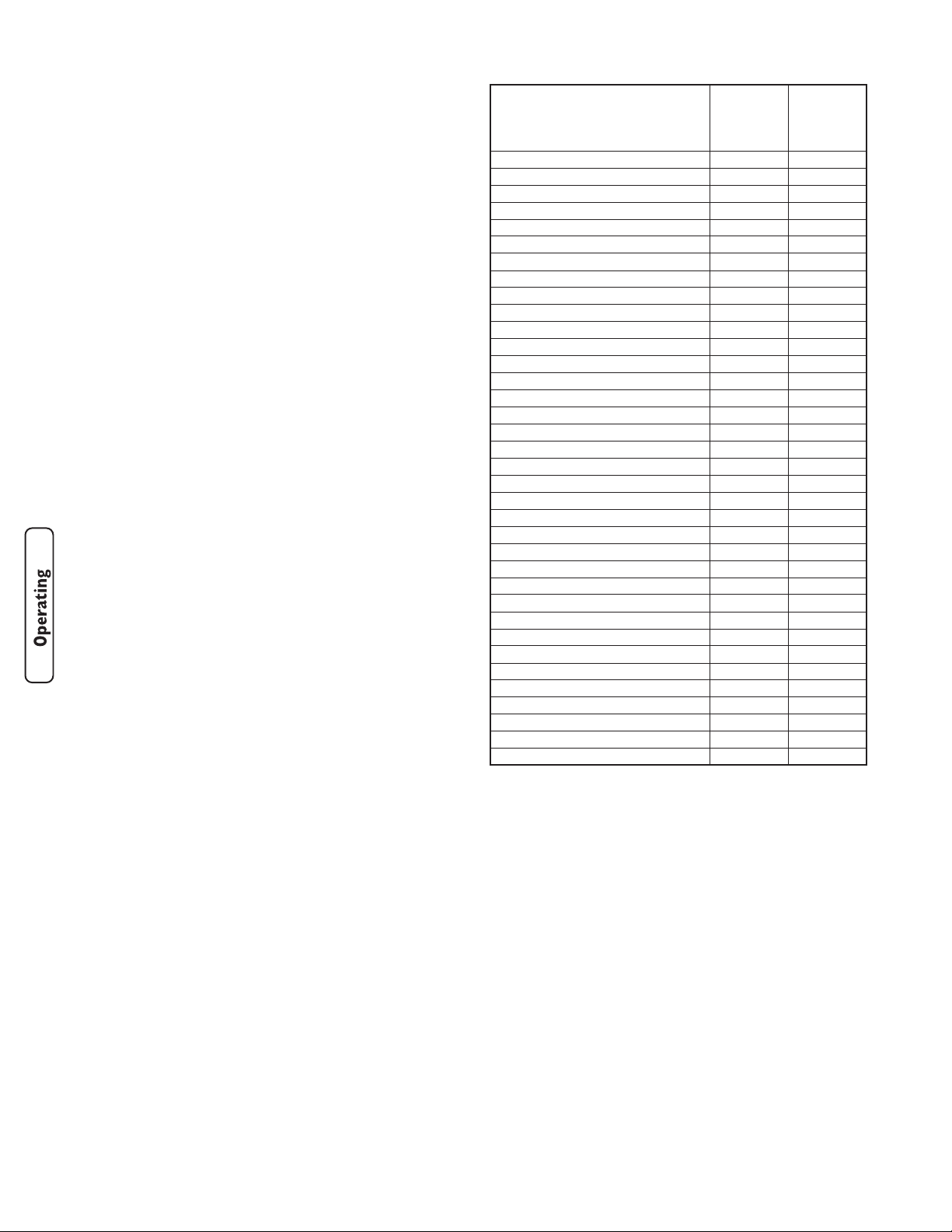
*Wattages listed are approximate only. Check tool or
appliance for actual wattage.
Figure 13 — Wattage Reference Guide
Tool or Appliance
Rated*
(Running)
Watts
Additional
Surge
(Starting)
Watts
Essentials
Light Bulb - 75 watt
75
-
Deep Freezer
500
500
Sump Pump
800
1200
Refrigerator/Freezer - 18 Cu. Ft.
800
1600
Water Well Pump - 1/3 HP
1000
2000
Heating/Cooling
Window AC - 10,000 BTU
1200
1800
Window Fan
300
600
Furnace Fan Blower - 1/2 HP
800
1300
Kitchen
Microwave Oven - 1000 Watt
1000
-
Coffee Maker
1500
-
Electric Stove - Single Element
1500
-
Hot Plate
2500
-
Family Room
DVD/CD Player
100
-
VCR
100
-
Stereo Receiver
450
-
Color Television - 27”
500
-
Personal Computer w/17” monitor
800
-
Other
Security System
180
-
AM/FM Clock Radio
300
-
Garage Door Opener - 1/2 HP
480
520
Electric Water Heater - 40 Gallon
4000
-
DIY/Job Site
Quartz Halogen Work Light
1000
-
Airless Sprayer - 1/3 HP
600
1200
Reciprocating Saw
960
960
Electric Drill - 1/2 HP
1000
1000
Circular Saw - 7 1/4”
1500
1500
Miter Saw - 10”
1800
1800
Table Planer - 6”
1800
1800
Table Saw/Radial Arm Saw - 10”
2000
2000
Air Compressor - 1-1/2 HP
2500
2500
Page 19
17
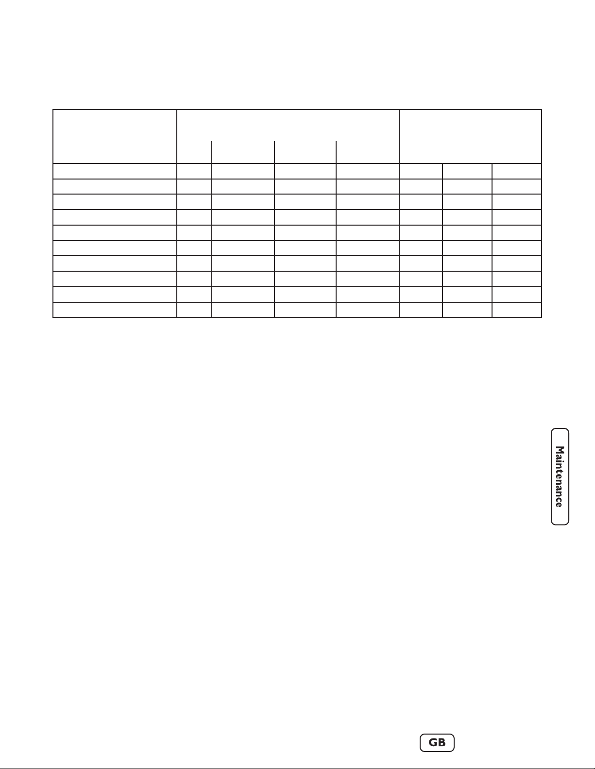
Maintenance Schedule
Follow the hourly or calendar intervals, whichever occurs first.
More frequent service is required when operating in adverse conditions noted below.
General Recommendations
Regular maintenance will improve the performance and
extend the life of the generator. See any authorized Briggs
& Stratton dealer for service. Never operate a
damaged or defective generator. To receive full value
from the warranty, the operator must maintain the
generator as instructed in this section.
All service and adjustments should be made at least once
each season. Follow the requirements in the “Maintenance
Schedule” chart above.
NOTE: Once a year you should clean or replace the
spark plug and replace the air filter. A new spark plug and
clean air filter assure proper fuel-air mixture and help
your engine run better and last longer.
NOTE: The alternator assembly rotates on a
prelubricated and sealed ball bearing that requires no
additional lubrication for the life of the bearing.
Emissions Control
Maintenance, replacement or repair of the emissions
control devices and systems may be performed by any
non-road engine repair establishment or individual. See
“Emissions Control System Warranty”.
Maintenance
Maintenance consists of keeping the unit clean. Operate
the unit in an environment where it will not be exposed
to excessive dust, dirt, moisture or any corrosive vapors.
Cooling air louvers on the enclosure must not become
clogged with snow, leaves, or any other foreign material.
Inspect cooling air slots and openings on generator. These
openings must be kept clean and unobstructed.
Check the cleanliness of the unit frequently and clean
when dust, dirt, oil, moisture or other foreign substances
are visible on its exterior/interior surface.
NOTE: DO NOT use direct spray from a garden hose to
clean generator. Water can enter the engine and
generator and cause problems.
Clean Debris
• Use a damp cloth to wipe exterior surfaces clean.
• Use a soft bristle brush to loosen caked on dirt or oil.
• Use a vacuum cleaner to pick up loose dirt and
debris.
1 Change oil sooner when operating under dirty or dusty conditions.
2 Replace more often under dirty or dusty conditions.
3 Check yearly only.
4 Clean more often under dirty or dusty conditions.
5 Replace every five years.
MAINTENANCE SCHEDULE
FILL IN DATES AS YOU
COMPLETE REGULAR SERVICE
SERVICE DATES
SERVICE DATES
MAINTENANCE TASK
Before
Each Use
Every 25 Hours
or Yearly
Every 50 Hours
or Yearly
Every 100 Hours
or Yearly
Clean debris
X
Check oil level
X
Change engine oil
X
1
Change oil filter
X
Service air cleaner pre-cleaner
X²
Replace air cleaner cartridge
X²
Replace spark plug
X
Check valve clearance
X
3
Clean cooling system
X
4
Replace fuel hoses and regulator
X
5
Page 20
18
www.briggsandstratton.com
Engine parts should be kept clean to reduce the risk of
overheating and ignition of accumulated debris. Use the
same instructions given above for the engine.
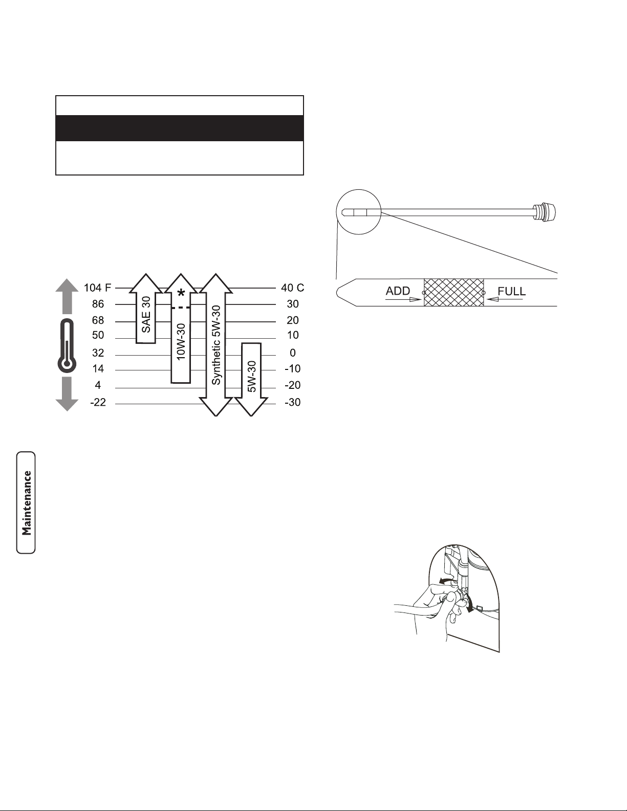
Oil
Oil Recommendations
NOTE: When adding oil to the engine crankcase, use
only high quality detergent oil classified “For Service SF,
SG, SH, SJ” or higher. DO NOT use special additives.
1. Choose a viscosity according to the following table:
*Check oil level frequently at higher temperatures.
NOTE: Synthetic oil meeting ILSAC GF-2, API
certification mark and API service symbol with “SJ/CF
ENERGY CONSERVING” or higher, is an acceptable oil at
all temperatures. Use of synthetic oil does not alter
required oil change intervals.
SAE 30: 40 °F and higher (5 °C and higher) is good for all
purpose use above 40°F, use below 40°F will cause hard
starting.
10W-30: 0 to 100 °F (-18 to 38 °C) is better for varying
temperature conditions. This grade of oil improves cold
weather starting, but may increase oil consumption at
80°F (27°C) or higher.
Synthetic 5W-30: -20 to 120 °F (-30 to 40 °C) provides
the best protection at all temperatures as well as
improved starting with less oil consumption.
5W-30: 40 °F and below (5 °C and below) is
recommended for winter use, and works best in cold
conditions.
Checking and Adding Oil
Oil level should be checked prior to each use or at least
every 8 hours of operation. Keep oil level maintained.
1. Make sure unit is on a level surface.
2. Remove roof (see Removable Roof and Battery
Access section).
3. Remove oil fill cap/dipstick and wipe clean with cloth.
4. Verify oil level is at the FULL mark on dipstick
(Figure 14).
5. If needed, slowly pour oil into oil fill opening.
RECHECK oil level. DO NOT overfill.
6. Replace and tighten dipstick.
7. Replace roof.
Changing Engine Oil and Filter
Remove the two screws from each plastic access cover
and remove both access covers from the two sides of the
generator enclosure.
Changing Oil
1. Slide oil drain tube from hose clamp and place oil
drain tube into approved container.
2. Push in and rotate oil drain fitting 1/4 turn
counterclockwise. Slowly pull outward until oil starts
draining (Figure 15). DO NOT pull oil drain fitting
off.
Figure 15 — Oil Drain Fitting
Figure 14 — Oil Fill Range
• DO NOT expose generator to excessive moisture, dust, dirt, or
corrosive vapors.
• DO NOT insert any objects through cooling slots.
Improper treatment of generator can damage it and
shorten its life.
CAUTION
Page 21
19
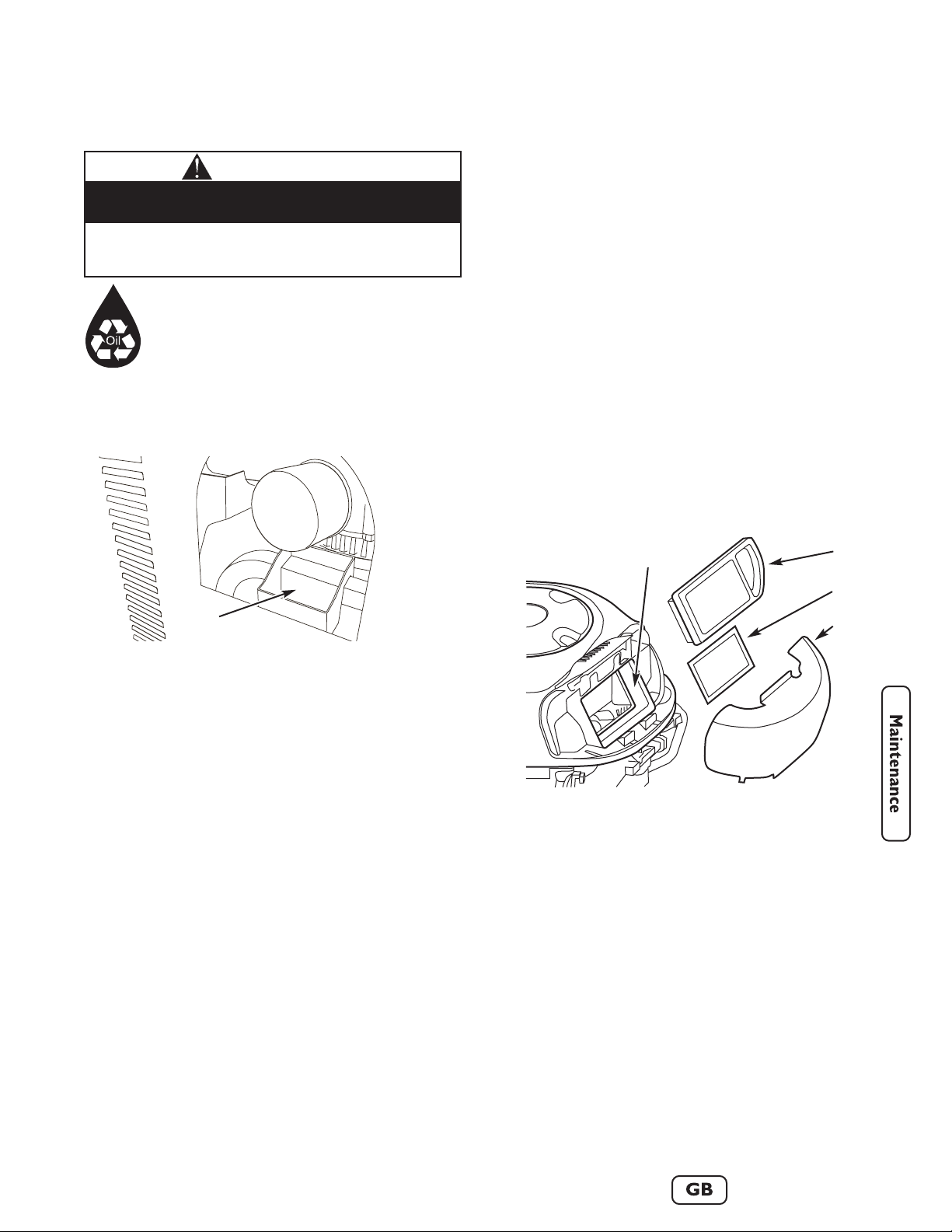
Service Air Cleaner Elements
Your engine will not run properly and may be damaged if
you run it with dirty air cleaner elements.
• Replace the air cleaner pre-cleaner every 25 hours
of operation or once each year, whichever comes
first.
• Replace the air cleaner cartridge every 100 hours of
operation or once each year. This air filter is UL
approved flame retardant material. Replace air filter
cartridge with original equipment replacement part.
• Replace more often if operating under dirty or dusty
conditions.
To service the air cleaner elements, follow these
steps:
1. Remove generator roof, as described in “Removable
Roof and Battery Access”.
2. Pull up on air cleaner cover handle and rotate toward
engine.
3. Remove air cleaner cover.
4. Carefully lift air cleaner cartridge and pre-cleaner
from housing. Figure 17 shows the air cleaner housing
area.
NOTE: To clean pre-cleaner, wash in soapy water.
Squeeze dry in a clean cloth. DO NOT wring. DO
NOT oil.
5. Vacuum air cleaner housing area carefully to prevent
debris from entering engine.
6. To clean cartridge, gently tap pleated paper side on a
flat surface.
3. When oil has drained, push oil drain fitting in and
rotate 1/4 turn clockwise until it locks in place.
4. Slide oil drain tube up into clamp on generator.
KEEP OUT OF REACH OF CHILDREN.
DON'T POLLUTE. CONSERVE
RESOURCES. RETURN USED OIL TO
COLLECTION CENTERS.
Changing Oil Filter
1. Place oil drain tray over tubing and slide it under oil
filter (Figure 16).
2. Grasp oil filter by hand and rotate counterclockwise.
Filter should detach from generator.
3. Before installing new filter, lightly oil filter gasket with
fresh, clean engine oil.
4. Carefully screw filter on until gasket contacts oil filter
adapter. Tighten by hand 1/2 to 3/4 turn more.
5. Remove oil drain tray from under oil filter and clean
up any spilled oil.
Fill engine with oil:
1. Add fresh recommended oil. Fill to FULL line on
dipstick.
2. Start and run generator for two minutes with no
loads connected and check for oil leaks.
3. Stop engine. Recheck oil level and add oil if required.
DO NOT overfill.
Figure 17 — Changing Air Filter Elements
A - Air cleaner housing
B - Air cleaner cartridge
C - Air cleaner pre-cleaner
D - Air cleaner cover
• Used motor oil has been shown to cause skin cancer in certain
laboratory animals.
• Thoroughly wash exposed areas with soap and water.
Avoid prolonged or repeated skin contact with used
motor oil.
CAUTION
A
B
C
D
Figure 16 — Changing Oil Filter with Oil Drain Tray
A - Oil drain tray placement
A
Page 22
20
www.briggsandstratton.com
IMPORTANT: DO NOT use pressurized air or solvents
to clean cartridge. Pressurized air can damage cartridge;
solvents will dissolve cartridge.
7. Place air cleaner pre-cleaner and cartridge into
housing. Cartridge must fit securely in housing.
8. Align tabs on cover with slots in housing and replace
cover.
9. Hook handle and close cover.
10. Replace roof.
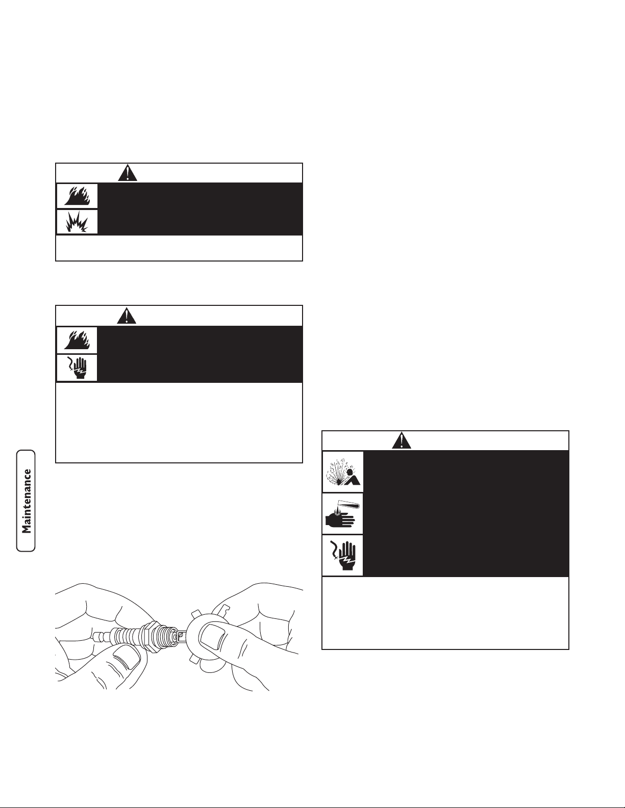
Service Spark Plug
Change the spark plug every 100 hours of operation or
once each year, whichever comes first. This will help your
engine to start easier and run better.
1. Clean area around spark plug.
2. Remove and inspect spark plug.
3. Check electrode gap with wire feeler gauge and reset
spark plug gap to recommended gap if necessary (see
Figure 18 and “Specifications”).
4. Replace spark plug if electrodes are pitted, burned or
porcelain is cracked. Use the recommended
replacement spark plug. See Specifications.
5. Install spark plug and tighten firmly.
Check Valve Clearance
Regular valve clearance check and adjustment will improve
performance and extend engine life. This procedure
cannot be done without partial engine disassembly and the
use of special tools. For this reason we recommend that
you have an authorized service dealer check and adjust
valve clearance at recommended intervals.
Engine Air Cooling System
Over time debris may accumulate in cylinder cooling fins
and cannot be observed without partial engine
disassembly. For this reason, we recommend you have an
authorized Briggs & Stratton service dealer clean the
cooling system per recommended intervals (see
“Maintenance Schedule”). Equally important is to keep top
of engine and rotating screen free from debris. See “Clean
Debris”.
Replace Fuel Hoses and Regulator
It is strongly recommend that you replace the fuel hoses
and fuel regulator after five years of use. Even though
these components are designed for outdoor use, constant
exposure to the elements and to sunlight causes
deterioration.
Charge Battery
IMPORTANT: The generator should be started at least
once every seven days and allowed to run at least
30 minutes. If this cannot be done, the battery will lose it’s
charge over time.
Figure 11 — Check Spark Plug Electrode Gap
When adjusting or making repairs to your
generator:
• Disconnect the spark plug wire from the spark plug and place the
wire where it cannot contact spark plug.
When testing for engine spark:
• Use approved spark plug tester.
• DO NOT check for spark with spark plug removed.
Unintentional sparking can result in fire or
electric shock.
WARNING
• DO NOT attempt to start your engine with filters or air cleaner
cover removed.
If air filter or air filter cover is not installed
correctly, serious injury or death could result
from backfire.
WARNING
• DO NOT dispose of battery in a fire.
• DO NOT allow any open flame, spark, heat, or lit cigarette during
and for several minutes after charging a battery.
• DO NOT open or mutilate the battery.
• Wear protective goggles, rubber apron, and rubber gloves.
• Remove watches, rings, or other metal objects.
• Use tools with insulated handles.
Storage batteries give off explosive hydrogen
gas during recharging.
Slightest spark will ignite hydrogen and cause
explosion.
Battery electrolyte fluid contains acid and is
extremely acidic.
Contact with battery contents will cause severe
chemical burns.
A battery presents a risk of electrical shock and
high short circuit current.
DANGER
Page 23
21
Service Battery
If it is necessary to service the battery, proceed as follows:
1. Open control panel cover.
2. Remove the 15 Amp fuse from the control panel
using the fuse removal tool.
3. Disconnect the negative battery cable, then
disconnect the positive battery cable.
4. Service or replace battery as required.
5. Connect the red battery cable to the battery positive
terminal (indicated by POSITIVE, POS, or (+)).
6. Connect the negative battery cable to the negative
battery terminal (indicated by NEGATIVE, NEG, or
(-)).
7. Ensure hardware on both positive and negative
battery terminals is secure.
8. Reinstall the 15 Amp fuse in the control panel.
Generator is now ready for starting and use.
Storage
The generator should be started at least once every seven
days and allowed to run at least 30 minutes. If this cannot
be done and you must store the unit for more than
30 days, use the following guidelines to prepare it for
storage:
1. While engine is still warm, change oil as described
earlier in “Changing Engine Oil and Filter”.
2. Remove spark plug and pour about 1 oz. (30 ml) of
engine oil into cylinder. Replace spark plug but
DO NOT connect spark plug wire.
3. Ensure fuel supply shut off valve is closed.
4. Press START/RUN/STOP switch momentarily to
distribute oil.
5. Connect spark plug wire to spark plug.
6. Clean the generator as outlined in “Generator
Cleaning”. Ensure that cooling air slots and openings
on generator are open and unobstructed.
7. Charge the battery, as described in “Charge Battery”.
8. If the generator is subjected to freezing temperatures,
disconnect battery cables from battery and move it to
a warmer location. Charge the battery before the
next season’s use.
If the generator is not operated once a month, the battery
should be removed and trickle charged regularly in order
to keep the battery charged and ready to start the
generator when needed. If battery voltage is too low, the
battery may not take a charge and you will need a new
battery.
If it is necessary to charge the battery, proceed as follows:
1. Open control panel cover.
2. Using the supplied fuse removal tool, remove the
15 Amp fuse from the control panel.
3. Disconnect the negative battery cable from the
negative battery terminal (indicated by NEGATIVE,
NEG, or (-).
4. Charge battery with battery charger set at 2 Amps
until full charge is indicated by battery charger.
IMPORTANT: If the battery fails to take a charge, it
must be replaced with the same type of 12 Volt DC,
AGM type, 33 Amp-Hour, battery. DO NOT replace with
liquid electrolyte lead-acid type battery.
5. Connect the negative battery cable to the negative
battery terminal (indicated by NEGATIVE, NEG, or
(-)).
6. Ensure hardware on both positive and negative
battery terminals is secure.
7. Reinstall the 15 Amp fuse in the control panel.
Generator is now ready for starting and use.
CAUTION
• DO NOT attempt to jump start the battery.
• Damage to equipment resulting from failure to follow this
instruction will void warranty.
Failure to disconnect negative battery cable will result
in equipment failure.
• DO NOT charge at a rate more than 2 Amps.
• Wear protective goggles, rubber apron, and rubber gloves.
Overcharging will cause the battery case to
crack and battery electrolyte to spill.
Battery electrolyte fluid contains acid and is
extremely acidic.
Contact with battery contents will cause severe
chemical burns.
WARNING
Page 24

22
www.briggsandstratton.com
Notes
Troubleshooting
Problem Cause Correction
Engine is running, but no AC
output is available.
1. Circuit breaker open or defective.
2. Fault in generator.
1. Reset or replace circuit breaker.
2. Contact local service facility.
Engine runs good at no-load but
"bogs down" when loads are
connected.
1. Short circuit in a connected load.
2. Generator is overloaded.
3. Shorted generator circuit.
4. Fuel pressure is incorrect.
5. LP fuel mixture is incorrect.
1. Disconnect shorted electrical load.
2. See "Don’t Overload Generator".
3. Contact local service facility.
4. See "The Gaseous Fuel System".
5. See "The Gaseous Fuel System".
Engine will not start; or starts and
runs rough.
1. 15 Amp fuse missing or blown.
2. Out of fuel.
3. Failed battery.
4. Loose, improper, or failed LP fuel
tank connection.
5. Ambient temperature too low to
replenish vapor in LP fuel tanks.
1. Install (new) 15 Amp fuse. See
“Control Panel Controls and
Features”.
2. Open fuel tank shut off valve(s);
check LP fuel tank(s).
3. Replace battery.
4. Check LP fuel tank connections.
5. Ensure you have two 20 pound LP
fuel tanks connected to generator..
Engine shuts down during
operation.
1. Out of fuel.
2. Engine oil low.
1. Check LP tank fuel shut off
valve(s), fill LP fuel tanks.
2. Check and add oil.
Page 25

23
Replacement Parts
Replacement parts are available from your authorized
Briggs & Stratton Service dealer. Each one carries a stock
of genuine Briggs & Stratton service parts and is equipped
with special service tools. Trained mechanics assure
expert repair service on all Briggs & Stratton products.
Only dealers advertising as “Authorized Briggs & Stratton”
are required to meet Briggs & Stratton standards.
When you purchase equipment powered by a Briggs &
Stratton engine, you are assured of highly skilled, reliable
service at more than 30,000 Authorized Service Dealers
worldwide, including more than 6,000 Master Service
technicians.
You may locate your nearest authorized Briggs & Stratton
Service Dealer in our dealer locator map on our web site
www.briggsandstratton.com or in the telephone directory
under “Engines” or “Generators” or similar category.
Maintenance Items
Many convenient and helpful service and maintenance
items are available from your authorized dealer. Some of
these items include:
Air cleaner cartridge
Engine oil
Maintenance kit
Oil filter
Pre-cleaner element
Resistor spark plug
Spark plug wrench
Spark tester
Touch-up paint
Product Specifications
Rated Maximum Power (LP*) . . . . . . . . . . . . . . . . .7.0 kW
Rated Maximum Load Current:
at 240 Volts . . . . . . . . . . . . . . . . . . . . . . . . . . .29.1 Amps
at 120 Volts . . . . . . . . . . . . . . . . . . . . . . . . . . .58.2 Amps
Rated AC Voltage . . . . . . . . . . . . . . . . . . . . .120/240 Volts
Rated Frequency . . . . . . . . . . . . . . . . . .60 Hz at 3600 rpm
Phase . . . . . . . . . . . . . . . . . . . . . . . . . . . . . . . . .Single Phase
Power Factor . . . . . . . . . . . . . . . . . . . . . . . . . . . . . . . . . .1.0
LP Fuel Supply Pressure . . . . . . . . . . . . . . . .11-14 in W.C.
NG Fuel Supply Pressure . . . . . . . . . . . . . . . . .5-7 in W.C.
Normal Operating Range -20°F (-28.8°C) to 104°F (40°C)
Output Sound Level . .81 dB(A) at 23 ft. (7 m) at full load
Shipping Weight . . . . . . . . . . . . . . . . . . . . . . . . . . . .280 lbs.
* Natural gas rating will depend on specific fuel but typical derating of generator is between
10 to 20% off the LP gas rating. The power ratings for an individual engine model are initially
developed by starting with SAE (Society of Automotive Engineers) code J1940 (Small Engine
Power & Torque Rating Procedure) (Revision 2002-05). Given both the wide array of products
on which our engines are placed, and the variety of environmental issues applicable to
operating the equipment, it may be that the engine you have purchased will not develop the
rated horsepower when used in a piece of power equipment (actual “on-site” power). This
difference is due to a variety of factors including, but not limited to, the following: differences
in altitude, temperature, barometric pressure, humidity, fuel, engine lubrication, maximum
governed engine speed, individual engine to engine variability, design of the particular piece of
power equipment, the manner in which the engine is operated, engine run-in to reduce friction
and clean out of combustion chambers, adjustments to the valves and carburetor, and other
factors. The power ratings may also be adjusted based on comparisons to other similar engines
utilized in similar applications, and will therefore not necessarily match the values derived using
the foregoing codes.
Engine
Bore . . . . . . . . . . . . . . . . . . . . . . . . . . . . .3.56 in. (90.6mm)
Stroke . . . . . . . . . . . . . . . . . . . . . . . . . . .3.06 in. (77.78mm)
Displacement . . . . . . . . . . . . . . . . . . . . . .30.59 in. (501 cc)
Spark Plug
Type: . . . . . . . . . . . . . .Champion RC12YC or Equivalent
Set Gap To: . . . . . . . . . . . . . . . . . . . .0.030inch (0.76mm)
Armature Air Gap: . . . . . . .0.010-0.014 in. (0.25-0.36mm)
Valve clearance with valve springs installed and piston 1/4 in. (6 mm)
past top dead center of compression stroke (check when engine is
cold).
Intake . . . . . . . . . . . . . . . . .0.003-0.005 in. (0.08-0.13 mm)
Exhaust . . . . . . . . . . . . . . . .0.005-0.007 in. (0.13-0.18 mm)
Oil Capacity (w/o filter) . . . . . . . . . .48 Ounces (1.4 Liters)
Oil Type: . . . . . . . . . . . . . . . . . . . . . .Synthetic SAE 5W-30
NOTE: For practical operation, the generator load should
not exceed 85% of rated wattage. Engine power will
decrease 3-1/2% for each 1,000 feet (300 meters) above
sea level and 1% for each 10° F (5.6° C) above 77° F
(25° C). Engine will operate satisfactorily at an angle up to
15°.
Page 26

24
www.briggsandstratton.com
Briggs & Stratton Corporation (B&S), the California Air Resources Board (CARB)
and the United States Environmental Protection Agency (U.S. EPA)
Emissions Control System Warranty Statement
(Owner’s Defect Warranty Rights and Obligations)
California, United States and Canada
Emissions Control Defects Warranty
Statement
The California Air Resources Board (CARB), U.S. EPA and
B&S are pleased to explain the Emissions Control System
Warranty on your small off–road engine (SORE). In
California, new small off–road engines model year 2006 and
later must be designed, built and equipped to meet the
State’s stringent anti–smog standards. Elsewhere in the
United States, new non–road, spark–ignition engines
certified for model year 1997 and later must meet similar
standards set forth by the U.S. EPA. B&S must warrant the
emissions control system on your engine for the periods of
time listed below, provided there has been no abuse, neglect
or improper maintenance of your small off–road engine.
Your emissions control system includes parts such as the
carburetor, air cleaner, ignition system, fuel line, muffler
and catalytic converter. Also included may be connectors
and other emissions related assemblies.
Where a warrantable condition exists, B&S will repair your
small off–road engine at no cost to you including diagnosis,
parts and labor.
Briggs & Stratton Emissions Control
Defects Warranty Coverage
Small off–road engines are warranted relative to emissions
control parts defects for a period of two years, subject to
provisions set forth below. If any covered part on your engine
is defective, the part will be repaired or replaced by B&S.
Owner’s Warranty Responsibilities
As the small off–road engine owner, you are responsible
for the performance of the required maintenance listed in
your Operating and Maintenance Instructions. B&S
recommends that you retain all your receipts covering
maintenance on your small off–road engine, but B&S
cannot deny warranty solely for the lack of receipts or for
your failure to ensure the performance of all scheduled
maintenance.
As the small off–road engine owner, you should however
be aware that B&S may deny you warranty coverage if
your small off–road engine or a part has failed due to
abuse, neglect, improper maintenance or unapproved
modifications.
You are responsible for presenting your small off–road
engine to an Authorized B&S Service Dealer as soon as a
problem exists. The undisputed warranty repairs should be
completed in a reasonable amount of time, not to exceed
30 days.
If you have any questions regarding your warranty rights
and responsibilities, you should contact a B&S Service
Representative at 1–414–259–5262.
The emissions warranty is a defects warranty. Defects are
judged on normal engine performance. The warranty is not
related to an in–use emissions test.
Briggs & Stratton Emissions Control
Defects Warranty Provisions
The following are specific provisions relative to your
Emissions Control Defects Warranty Coverage. It is in
addition to the B&S engine warranty for non–regulated
engines found in the Owner’s Manual.
1. Warranted Parts
Coverage under this warranty extends only to the
parts listed below (the emissions control systems
parts) to the extent these parts were present on the
engine purchased.
a. Fuel Metering System
• Cold start enrichment system (soft choke)
• Carburetor and internal parts
• Fuel Pump
• Fuel line, fuel line fittings, clamps
b. Air Induction System
• Air cleaner
• Intake manifold
c. Ignition System
• Spark plug(s)
• Magneto ignition system
d. Catalyst System
• Catalytic converter
• Exhaust manifold
• Air injection system or pulse valve
e. Miscellaneous Items Used in Above Systems
• Vacuum, temperature, position, time sensitive
valves and switches
• Connectors and assemblies
2. Length of Coverage
B&S warrants to the initial owner and each subsequent
purchaser that the Warranted Parts shall be free from
defects in materials and workmanship which caused
the failure of the Warranted Parts for a period of two
years from the date the engine is delivered to a retail
purchaser.
EMISSIONS CONTROL SYSTEM WARRANTY
Page 27

25
3. No Charge
Repair or replacement of any Warranted Part will be
performed at no charge to the owner, including
diagnostic labor which leads to the determination that
a Warranted Part is defective, if the diagnostic work
is performed at an Authorized B&S Service Dealer.
For emissions warranty service contact your nearest
Authorized B&S Service Dealer as listed in the
telephone directory under “Engines, Gasoline,”
“Gasoline Engines,” “Lawn Mowers,” or similar
category.
4. Claims and Coverage Exclusions
Warranty claims shall be filed in accordance with the
provisions of the B&S Engine Warranty Policy.
Warranty coverage shall be excluded for failures of
Warranted Parts which are not original B&S parts or
because of abuse, neglect or improper maintenance as
set forth in the B&S Engine Warranty Policy. B&S is
not liable to cover failures of Warranted Parts caused
by the use of add–on, non–original, or modified parts.
5. Maintenance
Any Warranted Part which is not scheduled for
replacement as required maintenance or which is
scheduled only for regular inspection to the effect of
“repair or replace as necessary” shall be warranted as
to defects for the warranty period. Any Warranted
Part which is scheduled for replacement as required
maintenance shall be warranted as to defects only for
the period of time up to the first scheduled
replacement for that part. Any replacement part that
is equivalent in performance and durability may be
used in the performance of any maintenance or
repairs. The owner is responsible for the
performance of all required maintenance, as defined in
the B&S Owner’s Manual.
6. Consequential Coverage
Coverage hereunder shall extend to the failure of any
engine components caused by the failure of any
Warranted Part still under warranty.
Emissions Durability Period and Air Index
Information On Your Engine Emissions
Label
Engines that are certified to meet the California Air
Resources Board (CARB) Tier 2 Emission Standards must
display information regarding the Emissions Durability
Period and Air Index. The engine manufacturer makes this
information available to the consumer on emission labels.
The Emissions Durability Period describes the number
of hours of actual running time for which the engine is
certified to be emissions compliant, assuming proper
maintenance in accordance with the Maintenance
Schedule. The following categories are used:
Moderate: Engine is certified to be emission
compliant for 125 hours of actual engine running time.
Intermediate: Engine is certified to be emission
compliant for 250 hours of actual engine running time.
Extended: Engine is certified to be emission
compliant for 500 hours of actual engine running time.
For example, a typical walk-behind lawn mower is used
20 to 25 hours per year. Therefore, the Emissions
Durability Period of an engine with an intermediate
rating would equate to 10 to 12 years.
The Air Index is a calculated number describing the
relative level of emissions for a specific engine family. The
lower the Air Index, the cleaner the engine. This
information is displayed in graphical form on the emissions
label.
Emissions Compliance Period On Engine
Emissions Compliance Label
After July 1, 2000 certain Briggs & Stratton engines will be
certified to meet the United States Environmental
Protection Agency (USEPA) Phase 2 emission standards.
For phase 2 certified engines, the Emissions Compliance
Period referred to on the Emissions Compliance label
indicates the number of operating hours for which the
engine has been shown to meet Federal emission
requirements. For engines less than 225 cc displacement,
Category C = 125 hours, B = 250 hours and A = 500
hours. For engines of 225 cc or more, Category C = 250
hours, B = 500 hours and A = 1000 hours.
This generator engine has an intermediate rating with an
Air Index of 2. The EPA Emissions compliance period is
Category C. The displacement of this engine is 501 cc.
Below is a generic representation of the emission label
typically found on a certified engine.
Page 28

26
www.briggsandstratton.com
The warranty period begins on the date of purchase by the first retail consumer or commercial end user, and continues for the
period of time stated in the table above. “Consumer use" means personal residential household use by a retail consumer.
“Commercial use" means all other uses, including use for commercial, income producing or rental purposes. Once equipment has
experienced commercial use, it shall thereafter be considered as commercial use for purposes of this warranty.
NO WARRANTY REGISTRATION IS NECESSARY TO OBTAIN WARRANTY ON BRIGGS & STRATTON PRODUCTS. SAVE
YOUR PROOF OF PURCHASE RECEIPT. IF YOU DO NOT PROVIDE PROOF OF THE INITIAL PURCHASE DATE AT THE TIME
WARRANTY SERVICE IS REQUESTED, THE MANUFACTURING DATE OF THE PRODUCT WILL BE USED TO DETERMINE
THE WARRANTY PERIOD.
ABOUT YOUR WARRANTY
We welcome warranty repair and apologize to you for being inconvenienced. Any Authorized Service Dealer may perform warranty
repairs. Most warranty repairs are handled routinely, but sometimes requests for warranty service may not be appropriate. For
example, warranty service would not apply if equipment damage occurred because of misuse, lack of routine maintenance,
shipping, handling, warehousing or improper installation. Similarly, the warranty is void if the manufacturing date or the serial
number on the equipment has been removed or the equipment has been altered or modified. During the warranty period, the
Authorized Service Dealer, at its option, will repair or replace any part that, upon examination, is found to be defective under normal
use and service. This warranty will not cover the following repairs and equipment:
• Normal Wear: Outdoor Power Equipment and engines, like all mechanical devices, needs periodic parts and service to
perform well. This warranty does not cover repair when normal use has exhausted the life of a part or the equipment.
• Installation and Maintenance: This warranty does not apply to equipment or parts that have been subjected to improper or
unauthorized installation or alteration and modification, misuse, negligence, accident, overloading, overspeeding, improper
maintenance, repair or storage so as, in our judgment, to adversely affect its performance and reliability. This warranty also
does not cover normal maintenance such as adjustments, fuel system cleaning and obstruction (due to chemical, dirt, carbon,
lime, etc.).
• Other Exclusions: This warranty excludes wear items such as oil gauges, o-rings, filters, fuses, spark plugs, starting
batteries, etc., or damage or malfunctions resulting from accidents, abuse, modifications, alterations, or improper servicing or
freezing or chemical deterioration. Accessory parts are excluded from the product warranty. This warranty excludes failures
due to acts of God and other force majeure events beyond the manufacturers control. Also excluded is used, reconditioned,
and demonstration equipment; equipment used for prime power in place of utility power and equipment used in life support
applications.
BRIGGS & STRATTON POWER PRODUCTS GROUP, LLC
JEFFERSON, WI, USA
Effective September 1, 2005 replaces all undated Warranties and all Warranties dated before September 1, 2005
LIMITED WARRANTY
Briggs & Stratton Power Products Group, LLC will repair or replace, free of charge, any part(s) of the equipment that is
defective in material or workmanship or both. Transportation charges on product submitted for repair or replacement under this
warranty must be borne by purchaser. This warranty is effective for the time periods and subject to the conditions stated below.
For warranty service, find the nearest Authorized Service Dealer in our dealer locator map at www.briggspowerproducts.com.
THERE IS NO OTHER EXPRESS WARRANTY. IMPLIED WARRANTIES, INCLUDING THOSE OF MERCHANTABILITY AND
FITNESS FOR A PARTICULAR PURPOSE, ARE LIMITED TO ONE YEAR FROM PURCHASE, OR TO THE EXTENT
PERMITTED BY LAW ANY AND ALL IMPLIED WARRANTIES ARE EXCLUDED. LIABILITY FOR INCIDENTAL OR
CONSEQUENTIAL DAMAGES ARE EXCLUDED TO THE EXTENT EXCLUSION IS PERMITTED BY LAW. Some states or
countries do not allow limitations on how long an implied warranty lasts, and some states or countries do not allow the
exclusion or limitation of incidental or consequential damages, so the above limitation and exclusion may not apply to you. This
warranty gives you specific legal rights and you may also have other rights which vary from state to state or country to country.
2 years
None
Consumer Use
Commercial Use
198182-E, Rev. 2 (11/21/05)
BRIGGS & STRATTON POWER PRODUCTS GROUP, LLC
7KW AND 10KW HOME GENERATOR OWNER WARRANTY POLICY
WARRANTY PERIOD
Page 29

This page reserved.
Page 30

Briggs & Stratton Power Products Group, LLC.
900 North Parkway
Jefferson, WI 53549
Copyright © 2006 Briggs & Stratton Power Products Group, LLC.
Reservados todos los derechos. Queda prohibida la reproducción o
transmisión total o parcial de este material, sea cual sea la forma y el
medio empleados para ello, sin el permiso previo y por escrito de
Briggs & Stratton Power Products Group, LLC.
Generador
Modelo Número 040248
Revisión _______
Número de Serie __________________
Motor
Modelo Número _______________________________
Número de Serie _______________________________
Fecha de compra
Muchas gracias por comprar este generador Briggs & Stratton de gran calidad. Nos alegra que haya depositado su
confianza en la marca Briggs & Stratton. Siempre que sea utilizado de acuerdo con las instrucciones de este manual, su
generador Briggs & Stratton le proporcionará muchos años de buen funcionamiento.
Este manual contiene información sobre seguridad para hacerle consciente de los riesgos asociados a los generadores de
combustible gaseoso y mostrarle cómo evitarlos. Briggs & Stratton no conoce necesariamente todas las aplicaciones que
este generador puede tener; por ello es importante que lea y entienda estas instrucciones. Conserve este manual para
futuras consultas.
Este generador requiere montaje final antes de ser usado. Consulte la sección Montaje de este manual, donde encontrará
instrucciones para el montaje final. Siga las instrucciones al pie de la letra.
Dónde encontrarnos
Usted no tendrá que ir muy lejos para encontrar el servicio técnico de Briggs & Stratton para su generador. Consulte las
Páginas Amarillas. Hay más de 30.000 proveedores de Briggs & Stratton autorizados en todo el mundo, proporcionando
un servicio de calidad. También puede ponerse en contacto con Atención al Cliente de Briggs & Stratton llamando al 1800-743-4115 o por Internet en www.briggsandstratton.com.
Page 31

1
Tabla de contenido
Reglas de seguridad ....................................................2
Descripción del equipo..............................................................................4
El sistema de combustible gaseoso.........................................................5
Montaje/instalación.....................................................6
Ubicación del generador ...........................................................................6
Fijación de los componentes del soporte de montaje del
depósito de combustible LP ....................................................................7
Instalación del depósito de combustible LP..........................................8
Comprobación de fugas en el circuito de combustible .....................9
Conexión de la batería............................................................................10
Controles y características del generador.............11
Panel de control........................................................................................12
Tomas eléctricas.......................................................................................13
Utilización del generador ........................................14
Encendido del motor...............................................................................14
Conexión de cargas eléctricas...............................................................14
Parada del motor......................................................................................14
No sobrecargar el generador................................................................16
Plan de mantenimiento ...........................................17
Aceite ..........................................................................................................18
Filtro de aire ..............................................................................................19
Bujía .............................................................................................................20
Holgura de la válvula................................................................................20
Sistema de refrigeración de aire............................................................20
Carga de la batería ...................................................................................20
Almacenamiento .......................................................................................21
Resolución de problemas.........................................22
Especificaciones del producto .................................23
Garantías ...................................................................24
Page 32

2
www.briggsandstratton.com
• NO deseche la batería tirándola al fuego.
• NO permita ninguna llama, chispa, calor o cigarrilo encendido
durante la carga de la batería y varios minutos después.
• NO abra ni manipule la batería.
• Use gafas protectoras, delantal y guantes de goma.
• No lleve relojes, anillos ni otros objetos metálicos.
• Utilice herramientas con mangos aislantes.
Las baterías de almacenaje emiten gas hidrógeno
explosivo durante la recarga.
La más mínima chispa inflamará el hidrógeno y
causará una explosión.
El fluido electrolito de la batería contiene ácido y es
extremadamente ácido.
El contacto con el contenido de la batería causará
quemaduras químicas graves.
Las baterías presentan un riesgo de descarga
eléctrica y de elevada corriente de cortocircuito.
PELIGRO
CONSERVE ESTAS INSTRUCCIONES
Normas de seguridad
Éste es el símbolo de alerta de seguridad. Sirve
para advertir al usuario de un posible riesgo para
su integridad física. Siga todos los mensajes de
seguridad que figuren después de este símbolo
para evitar lesiones o incluso la muerte.
El símbolo de alerta de seguridad ( ) se utiliza con una palabra
de señalización (PELIGRO, PRECAUCIÓN,
ADVERTENCIA), una imagen y/o un mensaje de seguridad
para advertir al usuario de un riesgo. PELIGRO indica un riesgo
que, de no evitarse, provocará la muerte o lesiones de gravedad.
ADVERTENCIA indica un riesgo que, de no evitarse, puede
provocar la muerte o lesiones de gravedad. PRECAUCIÓN
indica un riesgo que, de no evitarse, puede provocar lesiones
moderadas. Cuando se utiliza sin el símbolo de alerta,
PRECAUCIÓN indica una situación que podría producir daños
en el equipo. Siga en todo momento los mensajes de seguridad
para evitar o reducir el riesgo de lesiones y de muerte.
El fabricante no puede anticipar todas las posibles circunstancias
que podrían conllevar peligro. Por lo tanto, las advertencias de
este manual, así como las etiquetas y placas de la unidad, no
incluyen todo. Si usa un procedimiento, método de trabajo o
técnica operativa que no esté específicamente recomendada por
el fabricante, debe asegurarse de que no entraña peligro para
usted ni para otras personas. También debe asegurarse de que el
procedimiento, método de trabajo o técnica operativa elegida no
hace que el generador deje de ser seguro.
Símbolos de peligro y sus significados
• Utilice el generador SÓLO a la intemperie.
• Evite que los gases de escape entren en un espacio cerrado a
través de las ventanas, puertas, tomas de aire de ventilación u
otras aberturas.
• NO ponga en funcionamiento el generador dentro de ningún
edificio o espacio cerrado (aunque las ventanas y puertas estén
abiertas), ni en el compartimento para el generador de un vehículo
de recreo.
El generador en funcionamiento produce monóxido
de carbono, un gas venenoso, inodoro e incoloro.
La inhalación de monóxido de carbono puede
provocar náuseas, desmayos o incluso la muerte.
ADVERTENCIA
Los gases de escape del motor de este producto
contienen sustancias químicas declaradas cancerígenas
y causantes de malformaciones y otros defectos de
nacimiento por el Estado de California.
ADVERTENCIA
Fuego
Lea el
Manual
Presión
explosiva
Quemaduras
químicas
Explosión
Vapores
tóxicos
Superficie
caliente
Descarga eléctrica
El usar un generador en espacios interiores
le causará la muerte en unos minutos.
Los gases de combustión contienen monóxido
de carbono, un gas venenoso que usted no
puede ver ni oler.
NUNCA lo use dentro
del hogar ni en lugares
parcialmente cerrados
tales com garajes.
SOLO úselo al aire libre
y lejos de ventanas
abiertas, puertas y
respiraderos.
Page 33

3
• La instalación del generador debe cumplir todas las normas
locales. Para obtener información sobre la normativa local,
consulte con su proveedor de gas LP o de gas natural.
• Sujete firmemente los depósitos de combustible a la bandeja de
montaje del depósito de combustible LP como se describe en la
sección “Montaje”.
• Antes de utilizar el generador, se deben vaciar los tubos flexibles
del circuito de combustible y se debe probar su estanqueidad,
especialmente cuando se cambien los depósitos de combustible.
• No se permite ninguna fuga de combustible. NUNCA compruebe
si hay fugas con una cerilla o una llama viva. Los olores fuertes, los
síntomas de resfriados, la congestión nasal, etc. pueden indicar la
presencia de combustible gaseoso. Extreme las precauciones y el
sentido común cuando compruebe si hay fugas (consulte
“Comprobación de fugas en el circuito de combustible”).
• Una vez colocado el generador en su posición de funcionamiento,
inspeccione periódicamente el circuito de combustible y sus tubos
flexibles para determinar si presentan daños o un exceso de
desgaste. En caso afirmativo, sustituya los componentes afectados
utilizando ÚNICAMENTE piezas suministradas por el fabricante.
Los tubos flexibles y el regulador de combustible se deben
sustituir cada cinco años.
• Cuando el generador no esté en uso, cierre manualmente la(s)
válvula(s) de paso.
• NO utilice el generador si huele a combustible.
• NO fume cerca del generador. Limpie inmediatamente el aceite
que se haya podido derramar. Asegúrese de que no que queda
ningún material combustible en el compartimento del generador.
Mantenga limpia y libre de residuos la zona cercana al generador.
• NO suministre combustible gaseoso sin regular al generador.
Consulte la presión de suministro correcta en las especificaciones
del producto.
• NO permita que los tubos flexibles de combustible entren en
contacto con las superficies calientes.
• NO almacene los bidones de gas LP:
En interiores o cerca del generador.
En un edificio, garaje u otra zona cerrada.
Al alcance de los niños.
• El depósito de gas LP debe tener:
Un dispositivo de descarga de seguridad comunicado
directamente con el espacio de vapor del cilindro.
Un dispositivo de prevención de exceso de llenado (OPD)
que figure en la lista.
Homologación DOT o CAN/CSA-B339.
Una válvula de paso con una salida de combustible
compatible con un conector de depósito de tipo 1. No
se permite el uso de ningún otro conector de depósito
con este generador.
Un casquillo para proteger la válvula de paso de combustible.
• NO inserte ningún objeto extraño en la salida de la válvula del
depósito ni en los componentes del circuito de combustible.
• El sistema de suministro al depósito de LP debe permitir la salida
de vapor.
• Acuda a un proveedor acreditado de gas propano para llenar el
depósito de gas LP, hasta un máximo del 80%. Inspeccione
visualmente y recalifique el depósito después de cada llenado.
• Mantenga SIEMPRE los depósitos de gas LP en posición vertical.
• Manipule SIEMPRE los depósitos de gas LP con cuidado.
• El depósito de gas LP está equipado con un dispositivo térmico
interno que cortará permanentemente el flujo de gas si se supera
una temperatura de 115° C (240° C). En este caso, lleve el
depósito a su proveedor de combustible. Será necesario
determinar y corregir la causa del exceso de calor antes de volver
a utilizar el generador.
•
La circulación normal del gas por el regulador y los tubos flexibles
puede generar un zumbido. Los niveles de ruido bajos son normales
y no afectan al funcionamiento del generador. Si el zumbido es
excesivo, será necesario purgar el circuito de suministro.
El propano y el gas natural son extremadamente
inflamables y explosivos.
El fuego y las explosiones pueden causar quemaduras
graves o incluso la muerte.
ADVERTENCIA
• NO toque las superficies calientes y evite los gases de escape a
alta temperatura.
• Deje que el equipo se enfríe antes de tocarlo.
• Deje un espacio mínimo de 152 cm (5 pies) alrededor del
generador, incluida la parte superior.
• El Código de Normativa Federal (CFR, Título 36: Parques,
Bosques y Propiedad Pública) obliga a instalar una pantalla
apagachispas en los equipos con motor de combustión interno y a
mantenerla en buenas condiciones de funcionamiento, conforme a
la norma 5100-1C (o posterior) del Servicio Forestal de la USDA.
En el Estado de California, la ley exige el uso de una pantalla
apagachispas (Sección 4442 del Código de Recursos Públicos de
California). En otros estados puede haber leyes similares en vigor.
El motor en funcionamiento genera calor. La temperatura
del silenciador y de las zonas cercanas puede alcanzar o
superar los 65 ºC (150 ºF)
En caso de contacto, se pueden producir quemaduras
graves.
Los gases y el calor de escape pueden inflamar los
materiales combustibles y las estructuras o dañar el
depósito de combustible PL y provocar un incendio.
ADVERTENCIA
• Si utiliza el generador como sistema de reserva, notifíquelo a la
compañía eléctrica. Utilice equipos de transferencia aprobados
para aislar el generador del suministro de la compañía eléctrica.
• NO lo utilice bajo el efecto de las drogas o el alcohol.
• A pesar de la seguridad del diseño del generador, si éste se utiliza
con imprudencia, ignorando su mantenimiento o sin las debidas
precauciones, se pueden producir lesiones o incluso la muerte.
• Manténgase alerta en todo momento cuando utilice este equipo.
NUNCA lo utilice ni manipule en condiciones de fatiga física o
mental.
• NO toque los cables pelados ni las tomas.
• NO utilice el generador con cables eléctricos desgastados,
deshilachados, pelados o dañados.
• NO manipule el generador ni los cables eléctricos si se encuentra
en una zona húmeda, está descalzo o tiene las manos o los pies
mojados.
• NO permita que personas no cualificadas o niños utilicen o
reparen el generador.
• Si tiene que trabajar junto a una unidad en funcionamiento,
manténgase en una superficie aislada y seca para reducir el riesgo
de descarga eléctrica.
• En caso de accidente provocado por una descarga eléctrica,
desconecte inmediatamente el suministro de energía eléctrica y
póngase en contacto con las autoridades locales. Evite el contacto
directo con la víctima.
• Antes de realizar cualquier operación de mantenimiento en el
generador, desconecte el cable de la batería marcado como
NEGATIVE, NEG o (-). Una vez finalizada la operación, vuelva a
conectar el cable en último lugar.
• Quite el fusible de 15 A ANTES de manipular el equipo. Cuando
termine, vuelva a colocar el fusible de 15 A.
El generador produce voltaje peligroso.
El no aislar el generador del suministro de energía
eléctrica puede poner en peligro la integridad física de
los trabajadores de la compañía eléctrica, o incluso
provocarles la muerte debido a la energía de retorno.
ADVERTENCIA
• Este generador no cumple la regulación 33CFR-183 de la Guardia
Costera de EE.UU., y no debe utilizarse en aplicaciones marinas.
• La no utilización de generadores aprobados por la Guardia
Costera de EE.UU. podría causar daños materiales, lesiones graves
e incluso la muerte.
ADVERTENCIA
Page 34

4
www.briggsandstratton.com
Descripción del equipo
Lea atentamente este manual y familiarícese con
el generador. Conozca sus aplicaciones,
limitaciones y riesgos.
Esta unidad es un generador de corriente alterna (CA) de campo
giratorio accionado por motor. Suministra energía eléctrica para
iluminación, aparatos y herramientas compatibles. El campo
giratorio del generador funciona a unas 3.600 rpm accionado por
un motor de un solo cilindro. El generador funciona con gas
propano licuado (LP). Sólo puede funcionar con gas natural (NG)
tras la correspondiente conversión, que deberá ser realizada por
un técnico especialista cualificado.
La toma del generador incorpora una protección GFCI
(interruptor de circuito de fallo de conexión a tierra) y su
neutro está conectado a tierra para superar las inspecciones
OSHA en el lugar de trabajo.
El generador no funcionará si se conecta a un conectador
bipolar, ya que su seccionador de servicio también tiene un
neutro conectado a tierra. Si tanto el generador como el
seccionador de servicio de la vivienda o del edificio contienen un
neutro conectado a tierra, el GFCI se abre y evita que los
enchufes reciban corriente.
Si el generador se conecta al sistema eléctrico de un edificio, se
DEBE utilizar un conectador con conexión de neutro.
Este producto está pensado para uso residencial, como fuente de
energía eléctrica provisional para todo tiempo. Puede suministrar
energía para sistemas de calefacción, refrigeración o
comunicación, por ejemplo. Este producto no pertenece a la
categoría de reserva de emergencia según lo definido por la
norma NFPA 70 (NEC). NO utilice el generador para ningún
otro uso.
Se ha realizado el máximo esfuerzo para reunir en este manual la
información más precisa y actualizada. No obstante, el fabricante
se reserva el derecho de modificar, alterar o mejorar de
cualquier otra forma el generador y este documento en
cualquier momento y sin previo aviso.
• Utilice el generador sólo para los usos previstos.
• En caso de dudas sobre su uso, diríjase al distribuidor o a Briggs &
Stratton.
• Utilice el generador sólo en superficies planas.
• Para que el generador funcione correctamente es esencial que
haya un flujo adecuado y continuo de aire para su refrigeración y
ventilación.
• La puerta de acceso y el techo deben estar instalados siempre que
la unidad esté en funcionamiento.
• NO exponga el generador a humedad, polvo o suciedad en exceso
ni a vapores corrosivos.
• A pesar del diseño seguro del generador, usar este equipo
imprudentemente, descuidar su mantenimiento o no tener
cuidado puede causar lesiones o la muerte.
• Permanezca alerta todo el tiempo mientras trabaja con este equipo.
NUNCA trabaje con el equipo si está física o mentalmente cansado.
• NO encienda el motor con el filtro de aire o la tapa del filtro de
aire quitados.
• NO inserte ningún objeto por las ranuras de refrigeración.
• NO se suba en el generador ni en ninguna de sus partes. Pisar la
unidad puede causar estrés y romper piezas. Esto podría provocar
condiciones de funcionamiento peligrosas causando fugas de gases
de escape, combustible, aceite, etc.
• Si se sobrecalientan los dispositivos conectados, apáguelos y
desconéctelos del generador.
• Cierre el generador si:
-se corta la corriente eléctrica;
-el equipo produce chispas, humo o llamas;
-la unidad vibra excesivamente.
Un tratamiento inadecuado del generador puede estropearlo
y acortar su vida útil.
¡PRECAUCIÓN!
• NO suprima la conexión del neutro.
• La supresión de la conexión del neutro podría provocar daños
materiales, lesiones o incluso la muerte.
El GFCI no funcionará si se suprime la conexión del
neutro.
PELIGRO
• SÓLO PARA USO RESIDENCIAL. NO utilice el generador para
ningún otro uso.
• NO intente alterar la velocidad controlada. El generador
proporciona el voltaje y la frecuencia correcta cuando funciona a
una velocidad controlada.
• NO haga ninguna modificación en el generador.
Las velocidades de funcionamiento excesivamente altas
aumentan el riesgo de lesiones y de daños en el generador.
Las velocidades excesivamente bajas incrementan la carga de
trabajo.
¡PRECAUCIÓN!
• Véase “No sobrecargar el generador”.
• Encender el generador y dejar que el motor se estabilice antes de
conectar las cargas eléctricas.
• Conectar las cargas eléctricas en posición OFF, y encender (ON)
para que funcionen.
• Apagar las cargas eléctricas (OFF) y desconectarlas del generador
antes de detenerlo.
Sobrepasar la capacidad de potencia y amperaje del generador
puede dañar el generador y/o los dispositivos eléctricos
conectados a él.
¡PRECAUCIÓN!
Cuando ajuste o repare su generador:
• Desconecte el cable de la bujía de ésta y colóquelo donde no
pueda entrar en contacto con la bujía.
Cuando pruebe la bujía del motor:
• Utilice un comprobador de bujías homologado.
• NO compruebe la chispa sin la bujía instalada.
Las chispas involuntarias pueden provocar fuego o
descargas eléctricas.
ADVERTENCIA
Page 35

5
Protección contra los fallos de conexión a
tierra
Las tomas dobles disponen de protección GFCI (interruptor de
circuito de fallo de conexión a tierra). Este dispositivo cumple la
normativa federal, nacional y local vigente.
El GFCI protege contra las descargas eléctricas que se pueden
producir cuando un cuerpo humano se convierte en el medio a
través del cual la electricidad llega a tierra. Este fenómeno puede
producirse cuando el usuario toca un aparato o un cable con
corriente, una cañería u otro material conectado a tierra.
Con la protección de un GFCI, el usuario puede sentir la
descarga, pero el dispositivo corta la corriente lo bastante rápido
como para que una persona con una salud normal no sufra
ningún daño de gravedad.
Conexión al sistema eléctrico de un
edificio
El generador se debe conectar al sistema eléctrico de un edificio
a través de un conectador con conexión de neutro instalado por
un electricista cualificado. La conexión debe aislar la alimentación
del generador de la alimentación de la red pública y debe cumplir
todas las leyes y normas eléctricas vigentes.
IMPORTANTE: Se DEBE utilizar un conectador con conexión de
neutro para cambiar del suministro de la red eléctrica al del generador.
Responsabilidades del cliente
• Si considera la instalación de un conectador, lea y siga las
instrucciones de este manual.
• Siga un plan regular de mantenimiento, cuidado y uso del
generador, como se indica en este manual.
• Cuando no utilice el generador, desconecte y almacene
SIEMPRE en un espacio interior el cable utilizado para
conectar el generador y el cuadro de conexiones de entrada.
Para tomar decisiones bien fundadas y comunicarse eficazmente
con el técnico instalador.
Lea y comprenda la sección “Montaje” de este manual
antes de comenzar la instalación de su generador.
Puede solicitar la correcta instalación de su generador
poniéndose en contacto con el almacén donde lo compró, con
su proveedor Briggs & Stratton, con un electricista profesional
autorizado o con su proveedor de energía eléctrica.
La garantía del generador quedará ANULADA si las
conexiones de combustible permanentes no son
instaladas por parte de un profesional experto en
combustibles gaseosos autorizado.
La garantía del generador quedará ANULADA si se
instalan conexiones eléctricas permanentes al
generador.
El sistema de combustible gaseoso
El generador ha sido fabricado para funcionar con gas
licuado de petróleo. Si el generador se va a usar con gas
natural, el motor tendrá que ser reconfigurado usando el kit de
conversión proporcionado. Póngase en contacto con un técnico
autorizado experto en combustibles gaseosos para instalar este
kit.
El motor del generador está dotado de un sistema de mezcla de
combustible que cumple las especificaciones de California Air
Resources Board (autoridades competentes en materia de
contaminación del aire) para que los sistemas de combustible
duales estén a prueba de alteraciones inadecuadas. La unidad
puede funcionar con gas natural o vapor de propano licuado.
• Use combustible limpio, libre de humedades y partículas.
Usar combustibles que no se ajusten a los siguientes valores
recomendados podría causar problemas de funcionamiento:
• Se recomienda usar gas propano licuado (GPL) comercial de
grado HD5 con un nivel de energía combustible mínimo de
2500 BTU/pie cúbico, con un contenido de propileno máximo
del 5%, un contenido de gas butano o gases más pesados del
2,5% y un contenido mínimo de propano del 90%.
• Véase “Especificaciones” acerca de la presión de suministro
de gas.
Consumo de gas
Consulte en la siguiente tabla los requisitos de media y plena
carga para gas natural y vapor de LP.
Sólo electricistas cualificados y técnicos expertos en
combustibles gaseosos deben intentar la adaptación del
combustible o conectar permanentemente este
generador. Toda instalación debe cumplir estrictamente
con los códigos, estándares y normativas vigentes.
ADVERTENCIA
• Contacto con el conductor caliente y el conductor neutro al
mismo tiempo puede causar descargas eléctricas o quemaduras,
incluso aunque el circuito tenga protección GFCI.
• Antes de usar la toma eléctrica GFCI, SIEMPRE presione el botón
para asegurarse de que funciona.
El generador produce voltaje/corriente peligrosos.
ADVERTENCIA
Gas natural* Vapor de PL **
1/2 carga Carga completa 1/2 carga Carga completa
80 137 33 56
* = Gas natural en pies cúbicos por hora
* = Vapor de PL en pies cúbicos por hora
Requisitos de suministro de combustible
• El gas PL es más pesado que el aire y se acumula en zonas bajas.
• El gas natural es más ligero que el aire y se concentra en zonas
altas.
• La más mínima chispa puede inflamar estos combustibles y causar
una explosión.
• SI HUELE A GAS, cierre el suministro de gas al generador en la(s)
bombona(s)/toma de LP.
• Si el olor persiste, abandone la zona y llame inmediatamente a su
proveedor de gas o a los bomberos.
El propano y el gas natural son extremadamente
inflamables y explosivos.
El fuego y las explosiones pueden causar quemaduras
graves o incluso la muerte.
ADVERTENCIA
Page 36

6
www.briggsandstratton.com
Ubicación del generador
Considere los siguientes factores para determinar la posición de
uso correcta del generador:
• Instale la unidad en el exterior, en una superficie plana y
nivelada preparada para una ventilación adecuada. De esta
forma, se facilitará la dispersión de los gases de escape
mortales. NO instale el generador en lugares en los que los
gases de escape se puedan acumular o entrar en un edificio
que pueda estar ocupado.
Asegúrese de que los gases de escape no puedan entrar por
ventanas, puertas, tomas de aire de ventilación u otras
aberturas en un espacio cerrado en el que puedan
acumularse (Figura 1). Tenga en cuenta los vientos y las
corriente de aire preponderantes cuando elija la ubicación
del generador.
• Deje un espacio mínimo de 152 cm (5 pies) alrededor de la
carcasa y del soporte de montaje del depósito de LP,
incluida la parte superior. De esta forma, se reducirá el
riesgo de que el calor y los gases de escape inflamen los
materiales combustibles cercanos y se facilitará la
refrigeración adecuada y el mantenimiento del generador.
Montaje/instalación
El generador se puede utilizar después de montar los
componentes del soporte del depósito de combustible LP,
realizar las conexiones de combustible y comprobar el nivel de
aceite del motor.
Si tiene algún problema durante el montaje del generador, llame
a la línea de atención 1-800-743-4115. Tenga preparados los
números de modelo, revisión y serie, que figuran en la etiqueta
de características. Consulte la ubicación de la etiqueta de
características en “Controles y características del generador”.
Contenido del paquete
El generador se suministra con:
• Generador preacoplado al soporte de montaje
• Conjunto de bandeja de alojamiento del depósito de
combustible LP preacoplado al soporte de montaje
• Conjunto de tubos flexibles y regulador de combustible
preacoplado al generador
• Cubierta del depósito de combustible LP para todo tiempo
• Bolsa con la tornillería de fijación del depósito de
combustible LP
• Manual del operario
• Batería
• Bandeja de vaciado de aceite
• Pintura para retoques
• Un fusible de 15 A de repuesto
• Kit de conversión a NG
Deberá adquirir dos depósitos llenos de combustible LP DOT de
9 kg (20 libras) equipados con un dispositivo de prevención de
exceso de llenado (OPD) que figure en la lista.
Elevación del generador
PRECAUCIÓN El generador pesa más de 130 kg
(280 libras). Todas las fases de manipulación y traslado
del generador requieren el uso de herramientas, equipos
y profesionales cualificados. Cada depósito lleno de LP
pesa más de 9 kg (200 libras).
PRECAUCIÓN NO levante la unidad por la parte superior;
podría provocar daños en el generador.
Cada esquina del generador dispone de un orificio para horquilla
elevadora entre la base y el soporte de montaje. Consulte la
ubicación de los distintos elementos en “Controles y
características del generador”. Retoque los desconchones con la
pintura que se suministra a tal efecto.
• Deje un espacio mínimo de 152 cm (5 pies) alrededor del
generador, incluida la parte superior.
Los gases y el calor de escape pueden inflamar los
materiales combustibles y las estructuras o dañar el
depósito de combustible PL y provocar un incendio.
ADVERTENCIA
• Consultar la sección Mantenimiento acerca del rellenado de
aceite.
• La garantía quedará anulada si se producen daños como
consecuencia del incumplimiento de estas instrucciones.
Si intenta arrancar el motor sin comprobar que está
adecuadamente servido con el aceite recomendado,
provocará una avería.
¡PRECAUCIÓN!
Figura 1 — Espacio libre alrededor del generador
A - Abertura de escape
A
El usar un generador en espacios interiores
le causará la muerte en unos minutos.
Los gases de combustión contienen monóxido
de carbono, un gas venenoso que usted no
puede ver ni oler.
NUNCA lo use dentro
del hogar ni en lugares
parcialmente cerrados
tales com garajes.
SOLO úselo al aire libre
y lejos de ventanas
abiertas, puertas y
respiraderos.
Page 37

3, Inserte una arandela plana de 5/16” X 1” en un perno e
inserte el perno en uno de los orificios del perfil en L.
Apriete el perno a mano para introducirlo en el orificio del
soporte de montaje (consulte la Figura 3).
4. Repite tres veces el paso 3 hasta introducir un perno con
arandela en cada orificio del perfil en L.
5. Apriete cada perno hasta su tope con la herramienta
especificada. NO apriete en exceso para evitar que los
pernos se pasen de rosca.
6. Repita los pasos 2 a 5 para fijar el segundo perfil en L al
otro lado de los soportes de montaje.
Montaje de la varilla de fijación del depósito
Inserte uno de los extremos de la varilla roscada que se
suministra con la unidad en la posición de la bandeja del depósito
de combustible LP, como se muestra en la Figura 4. Apriete la
varilla a mano.
• Instale la unidad en un lugar en el que el agua procedente
de bombas, canalizaciones de desagüe, canalones de tejado,
sistemas de irrigación o aspersores no pueda inundarla,
mojar la caja ni penetrar por las aberturas de entrada o
salida de aire.
• Instale la unidad de forma que no dificulte ni afecte a
servicios tales como el teléfono, la electricidad, el
suministro de combustible, el aire acondicionado o el riego,
incluidos los servicios ocultos o subterráneos.
• Instale la unidad la unidad de forma que las aberturas de
entrada y salida de aire no queden obstruidas por hojas,
hierba, nieve, etc. Si los vientos pueden arrastrar estos
materiales, deberá construir un cortavientos para proteger
la unidad.
El generador se suministra acoplado a su soporte de montaje. A
menos que lo exija la normativa local, no es necesario construir
una solera de hormigón.
Si lo exige la normativa local, construya una solera de hormigón
de un grosor mínimo de 8 cm (3 pulgadas) y de una longitud y
un ancho 16 cm (6 pulgadas) superiores a las del conjunto de los
soportes del generador y del depósito de LP. Fije los soportes a
la solera con pernos de anclaje adecuados con un diámetro
mínimo de 6 mm (0,25 pulgadas).
Fijación de los componentes del soporte
de montaje del depósito de combustible
LP
Herramientas necesarias
Necesitar una de las herramientas siguientes para fijar el soporte
de montaje del depósito de combustible LP al soporte del
generador:
• Llave de cubo y trinquete de 13 mm (0,5 pulgadas) O
• Llave fija de 13 mm (0,5 pulgadas)
Unión de los soportes de montaje
1. Coloque el soporte e montaje del depósito de LP (con la
bandeja del depósito de combustible LP preacoplada) en el
suelo, del lado del generador al que se conectan los tubos
flexibles de combustible y el regulador.
Confirme que los orificios perforados en ambos soportes
de montaje son adyacentes (consulte la Figura 2).
2. Coloque un perfil en L de 50 cm (20 pulgadas) para unir los
soportes de montaje. Alinee los orificios del perfil con los
de los soportes, como se muestra en la Figura 2.
7
Figura 2 - Orificios del soporte de montaje y del perfil en L
A - Orificios del soporte de montaje
B - Perfil en L
B
A
Figura 3 - Inserción de pernos en los orificios del soporte de montaje
A - Soporte de montaje
B - Arandela plana
C - Perno
D - Perfil en L
C DBA
Figura 4 - Montaje de la varilla de fijación en la bandeja del depósito
de LP
A - Varilla de fijación
B - Bandeja del depósito de combustible LP
A
B
Page 38

Instalación del depósito de combustible LP
IMPORTANTE: Para obtener un rendimiento óptimo,
utilice dos (2) depósitos de combustible LP.
En esta sección se describe el método correcto de instalación y
comprobación de fugas de los depósitos de combustible LP del
generador. El sistema se suministra con una cubierta para el
depósito de combustible LP. Cubra los depósitos de combustible
LP siempre que estén conectados al generador.
Para instalar los depósitos de combustible LP:
1. Compruebe que las válvulas de paso de los dos depósitos
de combustible LP están cerradas (girar a tope hacia la
derecha).
2. Coloque cada depósito de LP en la bandeja con su válvula
de combustible hacia el generador (consulte la Figura 5).
3. Inserte el soporte de fijación del depósito de combustible
LP en la varilla roscada. Coloque el soporte de forma que
sus muescas queden en línea con los orificios de los
casquillos de los dos depósitos de combustible LP (consulte
la Figura 6).
Puede ser necesario mover los depósitos de combustible LP
y el soporte hasta conseguir la alineación correcta.
4. Inserte el conjunto de tubos flexibles y regulador de
combustible en la varilla roscada de forma que quede junto
al generador y apoyado en el soporte de fijación (Consulte
la Figura 7).
5. Enrosque la tuerca de mariposa a la varilla roscada girando
hacia la derecha. Apriete a mano la tuerca de mariposa
contra el conjunto de tubos flexibles/regulador de
combustible asegurándose de que las muescas del soporte
de fijación permanezcan enganchadas a los casquillos de los
depósitos de combustible y de que los depósitos queden
bien sujetos. Consulte la Figura 8.
6. Retire las tapas de protección de los conectores de las
válvulas de paso de los dos depósitos de combustible LP.
NO desecha las tapas de protección, deberá instalarlas
siempre que el depósito de combustible LP se desconecte
del generador.
7. Inserte el empalme del dispositivo de conexión izquierdo
(según se mira el generador y los depósitos de combustible
LP) en la salida de la válvula de depósito de combustible LP
(consulte la Figura 9). Asegúrese de que queda bien
insertado.
8
www.briggsandstratton.com
Figura 5 - Colocación correcta de los depósitos de combustible LP
A - Conector de la válvula de paso del depósito de combustible LP
B - Depósito de combustible LP
B
A
Figura 6 - Soporte de fijación correctamente alineado
A - Muesca del soporte sobre el casquillo del depósito de combustible
B - Soporte de fijación
BA
Figura 7 - Sustitución de los tubos flexibles y el regulador de
combustible
A - Soporte de fijación
B - Varilla roscada
C - Conjunto de tubos flexibles/regulador de combustible
A B C
Figura 8 - Depósitos de combustible LP correctamente sujetos
A - Depósito de combustible LP
B - Tuerca de mariposa
C - Conjunto de tubos flexibles/regulador de combustible
A
B
C
• La chispa más leve puede inflamar este combustible y provocar
una explosión.
• SI HUELE A GAS, cierre el suministro de gas al generador en
el(los) depósito(s) de combustible LP.
• Si el olor persiste, abandone la zona y llame inmediatamente a su
proveedor de gas o a los bomberos.
El gas propano es extremadamente inflamable y
explosivo.
El fuego y las explosiones pueden causar quemaduras
graves o incluso la muerte.
ADVERTENCIA
Page 39

2. Abra el suministro de combustible girando las válvulas de
paso de los dos depósitos de combustible LP a tope hacia la
izquierda.
3. Utilice una esponja, un trapo o un pequeño cepillo que no
sea metálico para aplicar la mezcla de jabón y agua en cada
punto identificado en la Figura 10.
4. Inspeccione cada punto indicado en la Figura 10. La
formación de burbujas indicará una fuga de combustible. El
aspecto de las burbujas será similar al que se muestra a
continuación.
5. Cierre las llaves de paso de los dos depósitos de
combustible LP girándolas a tope hacia la derecha).
8. Gire la tuerca de acoplamiento grande hacia la derecha y
apriete a mano hasta el tope.
NO pase de rosca la conexión.
NO utilice sellador para roscas.
NO apriete en exceso la unidad de acoplamiento.
NO utilice herramientas para apretar la conexión.
NOTA: Si no consigue hacer la conexión, repita el paso 7 o
consulte con un especialista en combustible LP.
9. Repita los pasos 7 y 8 para conectar el depósito de
combustible LP derecho.
10. Compruebe que los tubos flexibles de combustible no están
retorcidos ni en contacto con bordes afilados o superficies
que puedan calentarse con el funcionamiento del generador.
11. Haga una prueba completa de fugas de combustible
siguiendo las instrucciones de “Comprobación de fugas en
el circuito de combustible”.
Comprobación de fugas en el circuito de
combustible
1. Cree una mezcla de agua y jabón lavavajillas al 50%.
9
Figura 9 - Alineación correcta del dispositivo de conexión
A - Empalme el conector del tubo flexible de combustible
B - Conector de la válvula de paso del depósito de
combustible LP
B
A
Figura 10 - Puntos de comprobación de fugas
A - Soldaduras del depósito de combustible LP
B - Válvulas de paso del depósito de combustible en
las conexiones de la bombona
C - Tuercas de acoplamiento a las conexiones de las
válvulas de paso de los depósitos de combustible LP
D - Lado trasero de las uniones entre las tuercas de
acoplamiento y los tubos flexibles
E - Conexiones de la válvula en T de latón (todas las
uniones)
F - Conexión del regulador al tubo flexible de
combustible
G - Longitud total de todos los tubos flexibles de
combustible
H - Conexión del tubo flexible de combustible al
generador (todas las uniones)
A
D
B G H
G
E
F
E
C D
G
B G
• NO fume ni permita otras fuentes de ignición en la zona mientras
comprueba la presencia de fugas.
• Compruebe si hay fugas sólo en el EXTERIOR y en una zona bien
ventilada.
• NO compruebe si hay fugas con una cerilla o llama viva.
• NO compruebe si hay fugas con el generador en funcionamiento.
• Realice SIEMPRE una comprobación de fugas antes de usar el
generador por primera vez.
• Compruebe si hay fugas SIEMPRE que cambie un depósito de
combustible LP u otro componente del sistema.
• Compruebe si hay fugas SIEMPRE que cambie la ubicación del
generador.Compruebe si hay fugas al menos una vez al año o si el
generador no se ha utilizado durante más de 60 días.
El gas propano es extremadamente inflamable y
explosivo.
El fuego y las explosiones pueden causar quemaduras
graves o incluso la muerte.
ADVERTENCIA
Page 40

10
www.briggsandstratton.com
Techo y puerta de acceso extraíbles
La caja del generador incluye un techo y una puerta de acceso a
la batería extraíbles.
Para quitar el techo:
Hay dos tornillos a cada lado del techo, situados en las ranuras
con forma de media luna. Quite los cuatro tornillos y levante el
techo.
Para quitar la puerta de acceso:
1. Desconecte cualquier carga conectada al generador.
2. Quite el techo como se ha descrito anteriormente.
3. Quite el tornillo de la parte superior de la puerta de
acceso.
4. Extraiga la puerta de acceso tirando de ella y levantándola
para separarla de la base.
La puerta se separará de la caja del generador.
Para instalar la puerta de acceso a la batería y el techo:
1. Inserte la parte inferior de la puerta de acceso en la base.
2. Empuje la puerta de acceso hasta empotrarla en la carcasa.
3. Vuelva a colocar el tornillo de la puerta.
4. Vuelva a colocar el techo y sus tornillos.
Conexión de la batería
El generador se suministra con una batería sellada recargable de
plomo ácido, de 12 V CD y 33 AH, tipo AGM. Los cables de la
batería se conectan en fábrica.
La batería perderá algo de carga durante el envío y antes de la
instalación del generador. Si el voltaje de la batería es demasiado
bajo para arrancar el motor, cargue la batería como se describe
en “Mantenimiento”.
Si la batería no se carga, debe reemplazarse SÓLO por una del
mismo tipo, de 12 V CD, tipo AGM y 33AH.
6. Pulse y mantenga pulsado el interruptor START/RUN/
STOP (ARRANQUE/FUNCIONAMIENTO/PARADA) en la
posición START durante 5 segundos para eliminar la presión
del gas de los tubos flexibles. Consulte “Controles y
características del panel de control”.
7. Apriete o sustituya las conexiones que presenten fugas.
8. Repita los pasos 2 a 7 hasta que no se detecten fugas. NO
utilice el generador si no consigue eliminar las fugas. Solicite
ayuda a un especialista cualificado en combustible LP.
9, Cierre las válvulas de paso de los dos depósitos de
combustible LP hasta que esté preparado para utilizar el
generador.
10. Limpie los restos de jabón con agua fría limpia y seque con
un trapo.
11. Espere cinco minutos para evacuar el gas de la zona antes
de arrancar el generador.
NOTA: La comprobación de fugas se debe realizar en una zona
bien iluminada para ver si se forman burbujas. NO utilice una
linterna para comprobar la formación de burbujas.
Para retirar los depósitos de combustible
LP
1. Compruebe que la válvula de paso del depósito de
combustible LP está cerrada (girar a tope hacia la derecha).
2. Desconecte el tubo flexible de combustible del depósito de
LP girando a mano hacia la izquierda la tuerca de
acoplamiento grande (consulte la Figura 9).
3. Instale la tapa de protección en la salida de la válvula de
paso del depósito de combustible LP.
4. Quite la tuerca de mariposa de la varilla roscada girándola
hacia la izquierda. Levante y extraiga el conjunto de tubos
flexibles/regulador de la varilla roscada. Consulte las Figuras
7 y 8.
5. Levante y extraiga el soporte de fijación del depósito de
combustible LP de la varilla roscada (Consulte la Figura 6).
Puede ser necesario mover los depósitos de combustible LP
para soltar el soporte de fijación.
6. Levante con cuidado el depósito de combustible LP para
sacarlo de la bandeja.
Comprobar el nivel de aceite del motor
El generador sale de fábrica relleno de aceite sintético (API
SJ/CF 5W-30W). Esto permite al generador operar en una gran
variedad de condiciones climáticas y de temperatura. Antes de
arrancar el motor, compruebe el nivel de aceite y asegúrese de
que el motor está servido tal como se describe en
“Mantenimiento”.
NOTA: El uso de aceite sintético no altera los intervalos
de cambio de aceite indicados en la sección
Mantenimiento.
• NO deseche la batería tirándola al fuego.
• NO permita ninguna llama, chispa, calor o cigarrilo encendido
durante la carga de la batería y varios minutos después.
• NO abra ni manipule la batería.
• Use gafas protectoras, delantal y guantes de goma.
• NO lleve relojes, anillos ni otros objetos metálicos.
• Utilice herramientas con mangos aislantes.
Las baterías de almacenaje emiten gas hidrógeno
explosivo durante la recarga.
La más mínima chispa inflamará el hidrógeno y
causará una explosión.
El líquido electrolito de la batería es
extremadamente ácido.
El contacto con el contenido de la batería causará
quemaduras químicas graves.
Las baterías presentan un riesgo de descarga
eléctrica y de elevada corriente de cortocircuito.
PELIGRO
• Consultar la sección Mantenimiento acerca del rellenado de
aceite.
• La garantía quedará anulada si se producen daños como
consecuencia del incumplimiento de estas instrucciones.
Si intenta arrancar el motor sin comprobar que está
adecuadamente servido con el aceite recomendado,
provocará una avería.
¡PRECAUCIÓN!
Page 41

11
Controles y características del generador
Lea este Manual del usuario y reglas de seguridad antes de poner en marcha su generador.
Compare las ilustraciones con su generador, para familiarizarse con la ubicación de los diversos controles y ajustes. Guarde
este manual para futuras consultas.
A - Identificación del número de modelo— (grabado en la
parte superior de la tapa de la válvula) Identifica el modelo y tipo
de motor.
B - Pantalla giratoria — Evita que entren residuos en la
corriente de aire de refrigeración del motor.
C - Tapón de llenado y varilla de nivel de aceite — Para
comprobar el nivel de aceite y llenar el motor con el aceite
recomendado.
D - Panel de control — Se usa para varias funciones de
mantenimiento y funcionamiento. Véase “Controles y
características del panel de control” en la página siguiente.
E - Tubo de salida de aceite — Se proporciona para facilitar
el cambio de aceite.
F - Placa de datos de la unidad — Muestra los números de
modelo, serie y revisión.
G - Batería — Una batería sellada de 12 V CC, 33 AH
proporciona la energía para arrancar el motor. La batería tiene
carga continua siempre que el generador esté encendido.
H - Terminal de tierra del equipo— Para la conexión a
tierra del generador.
K - Orificios para horquilla elevadora — En cada esquina
inferior un orificio ayuda a levantar el generador y la base.
L - Entrada de combustible — Los componentes de
suministro de combustible se conectan al generador en este
punto.
M - Orificio de escape — El silenciador de alto rendimiento
reduce el ruido del motor conforme a la mayoría de las normas
de uso residencial. Incluye una pantalla apagachispas homologada.
N - Filtro de aceite — Filtra el aceite del motor para
prolongar la vida útil del generador.
P - Instrucciones de riesgo/arranque/parada — Siga estas
advertencias y procedimientos cuando utilice el generador.
R - Filtro de aire — Un filtro seco de espuma protege el
motor filtrando el polvo y los residuos del aire entrante.
Generator is shown with roof, oil filter access door, battery access door and control panel cover removed.
Consulte en las Figuras 5-8 los componentes importantes del depósito de combustible LP.
N
A
M
G
L
KH
CB
E
D
F
R
P
Page 42

12
www.briggsandstratton.com
Controles y características del panel de control
Compare esta ilustración con el panel de control de su generador, para familiarizarse con la ubicación de las tomas eléctricas, controles
y disyuntores:
A - Piloto LED — Se enciende cuando el generador está
produciendo voltaje.
B - Interruptor/Disyuntor de circuito de fallo de
conexión a tierra — Protege el generador de condiciones
de sobreintensidad y fallos de conexión a tierra. Debe estar
en la posición “ON” (ENCENDIDO) para suministrar
energía a todas las tomas eléctricas del panel de control.
C - Interruptor START/RUN/STOP
(ARRANQUE/FUNCIONAMIENTO/PARADA) —
Este interruptor de tres posiciones se usa de la siguiente
manera:
• La posición “START” arranca el generador. Presione y
manténgalo unos segundos para encender el generador.
•“RUN” es la posición del interruptor cuando el generador
está en funcionamiento.
• La posición “STOP” detiene el generador. Presionar y
sujetar hasta que el motor se pare.
D -120/240 V 30 A Toma eléctrica de bloqueo —
Suministra toda la energía de salida del generador y tiene
protección GFCI.
E - Disyuntores con pulsador de rearme — Protegen al
generador de posibles sobrecargas de corriente en la toma
eléctrica.
F - Tomas eléctricas de 120 V 20 A — Cada toma eléctrica
puede proporcionar 20 amperios de energía como máximo.
Las tomas eléctricas de 120 V tienen protección GFCI. La
carga total entre las cuatro tomas eléctricas no debe
exceder 7000 vatios.
G - Fusible de 15A — Protege los circuitos de corriente
continua (CC) del generador. Si el fusible no está o se ha
fundido, el motor no puede arrancar. Cambie el fusible sólo
por otro fusible ATO 15 A idéntico, disponible en la
mayoría de los almacenes de recambios.
GFCI
MAIN BREAKER
PUSH
TO
RESET
120/240V 30A
G
C
A
E
E
E
F
D
B
PUSH
TO
RESET
120V 20A
ALL RECEPTACLES GFCI-PROTECTED
120V 20A
15A FUSE
START/RUN/STOP
Page 43

13
Tomas eléctricas
Dispositivo de seguridad de 120/240 V,
30 A
Esta toma eléctrica (Figura 11) suministra toda la salida del
generador y está protegido contra la sobrecarga por un
disyuntor bipolar GFCI.
Use un enchufe NEMA L1430 con esta toma eléctrica. Conecte
un juego de cable de 4 hilos para cargas de 250 V CA a 30 A (o
superiores). Puede usar el mismo cable de 4 hilos para una carga
de 120 V. Examine el(los) juego(s) de cables antes de cada uso.
Almacene el(los) juego(s) de cables en un espacio interior.
Con el combustible PL, esta toma eléctrica soporta cargas de
120/240 V CA, de 60 Hz, monofásico, que requieren hasta
7000 vatios de potencia (7,0 kW) a 29,16 A para 240 V o dos
cargas independientes de 120 V a 29,16 A cada una.
Tomas eléctricas dobles de 120 V CA y
20 A
Cada una de las tomas eléctricas dobles (Figura 12) está
protegida contra sobrecargas por un disyuntor con pulsador de
rearme. Las cuatro tomas eléctricas están también protegidas
por un disyuntor bipolar CFGI.
Use cada toma eléctrica para operar 120 V CA, monofásico,
cargas eléctricas de 60 Hz que requieren hasta 2400 vatios
(2.4 kW) a 20 A de corriente cuando operan con combustible
PL. Use juegos de cable para cargas de 125 V CA a 30 A (o
superiores). Examine el(los) juego(s) de cables antes de cada uso.
NOTA: Mantenga todas las precauciones necesarias cuando
conecte cualquier alargador o dispositivo al generador.
Equipo de tierra
El generador dispone de una conexión a tierra del sistema que
conecta los componentes del bastidor a los terminales de tierra
de las tomas eléctricas de salida de CA. Conecte el generador a
tierra según los códigos, estándares y regulaciones vigentes.
La tierra del sistema está conectada al cable de CA neutro que, a
su vez, está conectado al bastidor del generador. El terminal de
tierra del equipo se muestra en “Controles y características del
generador”.
Requisitos especiales
Es posible que haya normas u ordenanzas locales y nacionales en
materia de seguridad e higiene en el trabajo aplicables al uso del
generador. Consulte con un electricista cualificado, un inspector
eléctrico o el organismo competente.
• En algunas zonas, es obligatorio registrar los generadores en
las compañías eléctricas locales.
• Si el generador se utiliza en una obra, puede ser necesario
cumplir normas y requisitos adicionales.
Figura 12 — Toma eléctrica de 120 V 20 A
• NUNCA intente conectar un dispositivo que requiera más
amperaje del que el generador o la toma eléctrica pueden
suministrar.
• NO sobrecargar el generador. Véase “No sobrecargar el
generador”.
Las tomas eléctricas pueden marcar un valor nominal mayor
que la capacidad de salida del generador.
¡PRECAUCIÓN!
• Véase “No sobrecargar el generador”.
• Encender el generador y dejar que el motor se estabilice antes de
conectar las cargas eléctricas.
• Conectar las cargas eléctricas en posición OFF, y encender (ON)
para que funcionen.
• Apagar las cargas eléctricas (OFF) y desconectarlas del generador
antes de detenerlo.
Sobrepasar la capacidad de potencia y amperaje del generador
puede dañar el generador y/o los dispositivos eléctricos
conectados a él.
¡PRECAUCIÓN!
Figura 11 — Toma eléctrica 120/240 V CA, 30 A
Juego de cables de 4 hilos
240 V
120 V
120 V
W (Neutro)
X (Caliente)
Y (Caliente)
NEMA L14-30
Tierra (Verde)
Page 44

14
www.briggsandstratton.com
Utilización del generador
Encendido del motor
Siga las siguientes instrucciones de puesta en marcha:
1. Asegúrese de que la unidad esté en una superficie plana.
IMPORTANTE: Si la unidad no se arranca y se utiliza en una
superficie plana, se pueden producir problemas de arranque y de
parada durante el funcionamiento.
2. Retire la tapa del panel de control con un destornillador.
3. Desconecte la(s) carga(s) del generador.
4. Abra la(s) válvula(s) de cierre del depósito de combustible
PL.
5. Confirme que el fusible de 15 A está instalado en el panel
de control.
6. Pulse y mantenga el interruptor START/RUN/STOP en la
posición START (Arranque) hasta que se encienda el piloto
LED.
IMPORTANTE: Si suelta el botón de la posición START antes
de que se encienda el piloto LED, el generador se parará.
NOTA: NO intente arrancar el motor durante más de
15 segundos. Tras cada intento, haga una pausa de 15 segundos
para evitar el sobrecalentamiento del sistema de arranque. Repita
el proceso hasta que arranque el motor.
NOTA: Cuando ponga en marcha el generador podría haber
aire en los conductos de combustible, especialmente tras
cambiar el depósito de combustible. Podría necesitar varios
ciclos de arranque para purgar ese aire y que el motor arranque.
Conexión de cargas eléctricas
1. Deje funcionar el motor durante dos minutos.
2. Abra la tapa del panel de control y confirme que el
interruptor principal del generador está en la posición ON
(cerrado). Consulte "Controles y características del panel
de control".
3. Enchúfelo y encienda la carga eléctrica deseada (120 y/o
240 V CA, monofásico, 60 Hz.)
3. Cierre la tapa del panel de control y ponga el seguro.
IMPORTANTE:
• NO conectar cargas de 240 V en las tomas eléctricas
dobles.
• NO conectar cargas trifásicas al generador.
• NO conectar cargas de 50 Hz al generador.
• NO SOBRECARGAR EL GENERADOR. Véase “No
sobrecargar el generador”.
Parada del Motor
1. Retire la tapa del panel de control con un destornillador.
2. Apagar todas las cargas eléctricas. Desconéctelas de las
tomas eléctricas del panel de control.
Nunca arranque o pare el motor cuando haya aparatos
eléctricos conectados y en funcionamiento.
3. Deje funcionar el motor durante dos minutos sin ninguna
carga para estabilizar las temperaturas internas del motor y
el generador.
4. Pulse y mantenga el interruptor START/RUN/STOP en la
posición STOP (Parada) hasta que se apague el piloto LED.
5. Cierre la(s) válvula(s) de cierre manual del combustible.
6. Cierre la tapa del panel de control y ponga el seguro.
• NO toque las superficies calientes y evite los gases de escape a
alta temperatura.
• Deje que el equipo se enfríe antes de tocarlo.
• Deje un espacio mínimo de 152 cm (5 pies) alrededor del
generador, incluida la parte superior.
El motor en funcionamiento genera calor. La
temperatura del silenciador y de las zonas cercanas
puede alcanzar o superar los 65 ºC (150 ºF)
En caso de contacto, se pueden producir
quemaduras graves.
Los gases y el calor de escape pueden inflamar los
materiales combustibles y las estructuras o dañar el
depósito de combustible PL y provocar un incendio.
ADVERTENCIA
Siga estos pasos después de montar, almacenar, trasladar, limpiar o
reparar el generador. NO utilice el generador sin haber leído y
comprendido TODAS advertencias e instrucciones del presente manual
del operario.
• Asegúrese de que el generador está bien montado.
• Inspeccione los tubos flexibles de suministro de combustible LP
para determinar si están quemados, rozados o retorcidos y si
están bien canalizados antes de cada uso. Los tubos deben
mantenerse a una distancia mínima de 8 cm (3 pulgadas) de las
superficies calientes.
• Compruebe todas las conexiones y los tubos flexibles de
combustible LP para detectar fugas. Consulte “Comprobación de
fugas en el circuito de combustible”
• Coloque el generador en una superficie nivelada y una zona bien
ventilada, a una distancia mínima de 152 cm (5 pies) de materiales
combustibles y edificios, incluida la parte superior. NO utilice el
generador sobre cubiertas de madera u otras superficies que
puedan inflamarse.
El gas propano es extremadamente inflamable y
explosivo.
El fuego y las explosiones pueden causar quemaduras
graves o incluso la muerte.
ADVERTENCIA
Page 45

15
Protección contra los fallos de conexión a
tierra
La unidad está equipada con un interruptor de circuito de fallo
de conexión a tierra (GFCI). Este dispositivo cumple la
normativa federal, nacional y local vigente.
Compruebe su disyuntor GFCI
Compruebe el disyuntor GFCI (véase “Controles y
características del panel de control”) cada mes, como se indica a
continuación:
1. Mientras el generador está en marcha y la tapa del panel de
control abierta, presione el botón blanco “Test”. El
disyuntor debe saltar (el mango se moverá hacia una
posición aproximadamente central), evitando así que los
enchufes reciban corriente.
2. Si el mango se mueve hacia el centro, reposicionar
moviendo firmemente hacia la posición “Off” (izquierda), y
después a la posición “On” (derecha).
Durante el uso del generador
Si el disyuntor salta durante el uso, normalmente se debe a la
presencia de cables o equipamiento defectuoso. Aun así,
compruebe el disyuntor como se indica a continuación:
1. Abrir la tapa del panel de control, desconectar las cargas,
reposicionar y comprobar el disyuntor tal como se describe
arriba. Deje funcionar el generador sin cargas durante 1
minuto.
2. Si el disyuntor pasa la comprobación, el equipamiento
eléctrico o alargadores podrían estar defectuosos. Cambie
el equipamiento eléctrico y cables defectuosos antes de
continuar el uso.
• NO use el generador.
• Póngase en contacto con un centro de servicio técnico de Briggs
& Stratton Power Products.
Si el disyuntor no salta:
¡PRECAUCIÓN!
• NO use el generador.
• Póngase en contacto con un centro de servicio técnico de Briggs
& Stratton Power Products.
Si el disyuntor no se reposiciona correctamente:
¡PRECAUCIÓN!
• NO use el generador.
• Póngase en contacto con un centro de servicio técnico de Briggs
& Stratton Power Products.
Si el disyuntor salta en el periodo de 1 minuto:
¡PRECAUCIÓN!
• Haga que un técnico cualificado compruebe todo el equipamiento
eléctrico y el cableado por si hubiera defectos.
• Sustituya el equipamiento eléctrico y el cableado o llévelo a un
centro de reparaciones cualificado.
Si el disyuntor pasa la comprobación:
¡PRECAUCIÓN!
Page 46

16
www.briggsandstratton.com
No sobrecargar el generador
Capacidad
Debe asegurarse de que su generador puede proveer los
suficientes vatios de potencia continua (vatiaje nominal) y vatios
de salida para los elementos que desee alimentar al mismo
tiempo. Siga estos sencillos pasos:
1. Seleccione los elementos que quiere alimentar al mismo
tiempo.
2. Sume la potencia nominal de esos elementos. Esa es la
cantidad de energía que su generador debe producir para
mantener sus elementos en funcionamiento. Consulte la
Figura 13.
3. Calcule cuántos vatios de salida necesitará. La potencia de
salida se refiere al corto arranque de energía que se
necesita para arrancar herramientas o dispositivos a motor,
como una radial o un refrigerador. Como no todos los
motores arrancan al mismo tiempo, el total de vatios de
salida puede calcularse añadiendo sólo el elemento con la
potencia de salida más alta al total de vatios de potencia
continua que obtuvimos en el paso 2.
Ejemplo:
Vatios de potencia continua totales = 3075
Potencia de salida adicional más alta = 1800
Salida total del generador requerida = 4875
Control de la energía
Para prolongar la vida de su generador y los aparatos que
conecte a él, es muy importante tener cuidado cuando se le
añaden cargas eléctricas. No deber haber nada conectado a las
tomas del generador antes de encender el motor. El modo
seguro y correcto de gestionar la energía del generador es
añadir las cargas secuencialmente, como se indica a continuación:
1. Sin tener nada conectado al generador, encienda el motor
tal como se describe en este manual.
2. Conecte y encienda la primera carga, preferiblemente la
mayor que usted tenga.
3. Permita que la salida del generador se estabilice (el motor
funciona suavemente y el aparato funciona adecuadamente).
4. Conecte y encienda la próxima carga.
5. De nuevo, permita que el generador se estabilice.
6. Repita los pasos 4 y 5 para cada carga adicional que usted
tenga.
Nunca añada cargas que sobrepasen la capacidad del
generador. Tenga especial cuidado en contar con las
cargas adicionales en la capacidad del generador, como
se describe arriba.
*La potencia que aparece en la lista es aproximada. Compruebe
la herramienta o aparato eléctrico para obtener la potencia real.
Figura 13 — Guía de referencia de potencia
Herramienta o aparato
Vatios de potencia
continua
Vatios de potencia
de salida adicional
Básicos
Bombilla de 75 vatios 75 Congelador industrial 500 500
Bomba para sumideros 800 1200
Refrigerador / Congelador – 18 pies
cúbicos
800 1600
Bomba de agua – 1/3 HP 1000 2000
Calefacción / Aire Acondicionado
Aire acondicionado de ventana –
10.000 BTU
1200 1800
Ventilador de ventana 300 600
Ventilador de caldera – 1/2 HP 800 1300
Cocina
Horno microondas – 1000 vatios 1000 Cafetera 1500 Estufa eléctrica – Elemento simple 1500 Plancha de cocina 2500 -
Habitación familiar
Reproductor de DVD/CD 100 VCR 100 Receptor estéreo 450 Televisión en color – 27" 500 Ordenador personal con monitor de 17" 800 -
Otros
Sistema de seguridad 180 -
Radio-reloj AM/FM 300 Dispositivo de apertura de garage – 1/2
HP
480 520
Calentador de agua eléctrico – 150
litros aprox. (40 galones)
4000 -
Taller
Luz halógena de cuarzo para trabajar 1000 -
Rociador sin aire – 1/3 HP 600 1200
Sierra sable 960 960
Taladro eléctrico – 1/2 HP 1000 1000
Sierra Radial – 10" 1500 1500
Sierra inglete – 10" 1800 1800
Cepilladora de mesa – 6" 1800 1800
Sierra de mesa / Sierra de brazo radial
– 10"
2000 2000
Compresor de aire – 1-1/2 HP 2500 2500
Page 47

17
Plan de mantenimiento
Siga los intervalos de horas o de calendario, los que sucedan antes.
Si opera en condiciones adversas (señaladas más abajo) es necesario un mantenimiento más frecuente.
1 Cámbielo antes si el motor funciona en condiciones de suciedad o polvo.
2 Sustitúyalo con más frecuencia en condiciones de suciedad o polvo.
3 Comprobar una vez al año.
4 Sustitúyalo con más frecuencia en condiciones de suciedad o polvo.
5 Sustituya estos elementos cada cinco años.
PLAN DE MANTENIMIENTO
ANOTE LAS FECHAS A MEDIDA QUE
LLEVE A CABO LAS OPERACIONES DE
MANTENIMIENTO
FECHAS DE MANTENIMIENTO
FECHAS DE MANTENIMIENTO
TAREAS DE MANTENIMIENTO
Antes de
cada uso
Cada 25 horas o
una vez al año
Cada 50 horas o
una vez al año
Cada 100 horas o
una vez al año
Limpie los residuos
X
Compruebe el nivel de aceite
X
Cambie el aceite del motor
X
1
Cambie el filtro del aceite
X
Mantenimiento del prefiltro del filtro de
aire
X²
Cambie el cartucho del filtro de aire
X²
Sustituya la bujía
X
Comprobación de holgura de las válvulas
X
3
Limpie el sistema de refrigeración
X
4
Sustitución de los tubos flexibles y el
regulador de combustible
X
5
Recomendaciones generales
El mantenimiento periódico mejorará el rendimiento y
prolongará la vida útil del generador. Acuda a un distribuidor
autorizado de Briggs & Stratton para reparar la unidad. Nunca
haga funcionar un generador dañado o defectuoso. Para
beneficiarse completamente de la garantía el operador debe
mantener el generador tal como se explica en esta sección.
La totalidad de las reparaciones y los ajustes se deberán realizar
al menos una vez por temporada. Siga las indicaciones del cuadro
“Plan de mantenimiento”.
NOTA: Una vez al año debería limpiar o cambiar la bujía y
cambiar el filtro de aire. Una bujía nueva y un filtro de aire
limpio aseguran la mezcla adecuada de combustible y aire y
contribuyen a mejorar el rendimiento del motor y a prolongar su
vida útil.
NOTA: El alternador rota en un cojinete prelubricado y sellado
que no necesita lubricación adicional durante su vida útil.
Control de emisiones
Cualquier establecimiento o individuo especializado en la
reparación de motores que no sean de automoción puede
encargarse del mantenimiento, la sustitución y la reparación de
los dispositivos y sistemas de control de emisiones. Véase
“Garantía de control de emisiones”.
Mantenimiento
El mantenimiento consiste en mantener limpia la unidad. Haga
funcionar la unidad en un espacio limpio y seco, sin exceso de
polvo, suciedad, humedad o vapores corrosivos. Las ranuras del
aire de la caja del generador no deben quedar obstruidas por
hojas ni por ningún otro tipo de suciedad o material. Inspeccione
las ranuras y aberturas de aire de refrigeración del generador.
Las aberturas deben estar limpias y despejadas.
Compruebe la limpieza de la unidad frecuentemente y límpiela
cuando haya polvo, suciedad, aceite, humedad o sustancias ajenas
en su superficie exterior o interior.
NOTA: NO rocíe el generador directamente con una manguera
de jardín para limpiarlo. El agua podría penetrar en el motor del
generador y causar problemas.
Limpie los residuos
• Utilice un trapo húmedo para limpiar las superficies
exteriores.
• Utilice un cepillo de cerda suave para eliminar los restos de
suciedad o aceite endurecidos.
• Utilice una aspiradora para eliminar los restos sueltos de
suciedad.
Page 48

18
www.briggsandstratton.com
Mantenga limpios los componentes del motor para reducir el
riesgo de sobrecalentamiento e ignición de los residuos
acumulados. Use estas mismas instrucciones para el motor.
Aceite
Recomendaciones sobre el aceite
NOTA: Cuando añada aceite al cárter del motor, utilice sólo
aceite detergente de alta calidad con clasificación de servicio SF,
SG, SH, SJ o superior. NO utilice aditivos especiales.
1. Elija una viscosidad conforme a la siguiente tabla:
*Compruebe el nivel de aceite con frecuencia a temperaturas
superiores.
NOTA: Todo aceite sintético que cumpla las especificaciones
ILSAC GF-2, con marca de certificación API y con símbolo de
servicio API con SJ/CF ENERGY CONSERVING o superior es un
aceite aceptable a todas las temperaturas. El uso de aceite
sintético no altera los intervalos de cambio de aceite indicados.
SAE 30: 5 ºC (40 °F) y superior es adecuado para todo tipo de
usos por encima de 5 ºC (40 °F). El uso por debajo de 5 ºC (40
°F) provocará dificultades de arranque.
10W-30: -18 a 38 °C (0 a 100 °F) es mejor en caso de
temperatura variable. Este grado de aceite mejora el arranque en
climas fríos, pero puede aumentar el consumo de aceite a 27 °C
(80 °F) o temperaturas superiores.
Sintético 5W-30: -30 a 40 °C (-20 a 120 °F) proporciona la
mejor protección a todas las temperaturas al tiempo que mejora
el arranque y reduce el consumo de aceite.
5W-30: 5 °C (40 °F) e inferior es el aceite recomendado para el
invierno y funciona mejor en condiciones de frío.
Comprobar y añadir aceite
Compruebe el nivel de aceite antes de cada uso o cada 8 horas
de funcionamiento, como mínimo. Rellene si es necesario.
1. Asegúrese de que la unidad esté en una superficie plana.
2. Retirar el techo (véase la sección “Techo y puerta de
acceso extraíbles).
3. Quite el tapón de llenado y la varilla de nivel de aceite y
límpielos con un trapo.
4. Compruebe que el nivel de aceite llega a la marca FULL
(lleno) de la varilla (Figura 14).
5. Vierta lentamente el aceite por la abertura de llenado.
VUELVA A COMPROBAR el nivel de aceite. NO añada
aceite en exceso.
6. Vuelva a colocar la varilla de nivel de aceite y ajústela en su
posición.
7. Vuelva a poner el techo.
Cambio del aceite del motor y del filtro
Extraiga los dos tornillos de cada tapa de acceso de plástico y
retire ambas tapas de los dos lados de la caja del generador.
Cambio del aceite
1. Deslice el tubo de vaciado del aceite para soltarlo de la
abrazadera y deposite el tubo en un contenedor adecuado.
2. Presione y gire el adaptador de vaciado de aceite ¼ de
vuelta hacia la izquierda. Tire lentamente hasta que empiece
a salir el aceite (Figura 15). NO suelte el adaptador de
vaciado de aceite.
Figura 15 — Ajuste de la manguera de vaciado de aceite
Figura 14 — Indicador del nivel de aceite
• NO exponga el generador a humedad, polvo o suciedad en exceso
ni a vapores corrosivos.
• NO inserte ningún objeto por las ranuras de refrigeración.
Un tratamiento inadecuado del generador puede estropearlo
y acortar su vida útil.
¡PRECAUCIÓN!
Page 49

19
Elementos del filtro de aire
Si se utiliza con un filtro de aire sucio, el motor no funcionará
correctamente y puede sufrir daños.
• Cambie el pre-filtro del filtro de aire cada 25 horas de
funcionamiento o una vez al año, lo que suceda antes.
• Cambie el cartucho del filtro de aire cada 100 horas de
funcionamiento o una vez al año, lo que suceda antes. Este
filtro de aire está homologado por UL y es de material
retardante de la llama. Sustituya el cartucho del filtro de
aire con una pieza de recambio del equipamiento original.
• Haga cambios más frecuentes si trabaja en zonas donde
abunda la suciedad y el polvo.
Para revisar el filtro de aire, siga estos pasos:
1. Retire el techo del generador, tal como se describe en
“Techo y puerta de acceso extraíbles”.
2. Tire del mango de la tapa del filtro de aire y gírelo hacia el
motor.
3. Retire la tapa del filtro de aire.
4. Saque cuidadosamente el cartucho del filtro de aire y el
prefiltro de su sitio. La Figura 17 muestra el lugar donde ha
de colocarse el filtro de aire.
NOTA: Para limpiar el prefiltro, lave con agua jabonosa.
Escúrralo en un paño limpio hasta secarlo. NO LO RETUERZA.
NO lo lubrique con aceite.
5. Aspire el hueco del filtro de aire cuidadosamente para
evitar la entrada de residuos en el motor.
6. Para limpiar el cartucho, golpee suavemente el lado del
papel plisado en una superficie plana.
3. Una vez vaciado todo el aceite, presione el adaptador de
vaciado de aceite y gírelo 1/4 de vuelta hacia la derecha
hasta que quede bien sujeto en su sitio.
4. Deslice el tubo de vaciado del aceite hasta volverlo a ajustar
en la abrazadera del generador.
MANTENER FUERA DEL ALCANCE DE LOS
NIÑOS. NO CONTAMINE. CONSERVE LOS
RECURSOS. DEPOSITE EL ACEITE USADO
EN UN PUNTO DE RECOGIDA.
Cambio del filtro de aceite
1. Coloque la bandeja de vaciado de aceite sobre la tubería y
deslícela para situarla debajo del filtro de aceite (Figura 16).
2. Agarre el filtro del aceite con la mano y gírelo hacia la
derecha. El filtro debería desprenderse del generador.
3. Antes de instalar un nuevo filtro, unte ligeramente la junta
del filtro con aceite limpio de motor.
4. Vuelva a colocar el filtro con cuidado de manera que la
junta quede en contacto con el adaptador del filtro de
aceite. Ajústelo a mano girándolo 1/2 vuelta o 1/4 de vuelta
más.
5. Retire la bandeja de vaciado de aceite de debajo del filtro y
limpie bien los restos de aceite.
Rellene el motor con aceite:
1. Añada el aceite recomendado y nuevo. Llene hasta la marca
FULL (lleno) de la varilla de nivel.
2. Encienda el generador y déjelo funcionar durante dos
minutos sin cargas conectadas para comprobar que no hay
pérdidas de aceite.
3. Pare el motor. Vuelva a comprobar el nivel de aceite y si
fuera necesario añada un poco. NO añada aceite en exceso.
Figura 17 — Cambio de los elementos del filtro de aire
A - Ubicación del filtro de aire.
B - Cartucho del filtro de aire.
C - Prefiltro del filtro de aire.
D - Tapa del filtro de aire.
• El aceite usado provoca cáncer de piel en determinados animales
de laboratorio.
• Lave perfectamente las partes expuestas con jabón y agua.
Evite el contacto prolongado o repetido de la piel con el
aceite usado del motor.
¡PRECAUCIÓN!
A
B
C
D
Figura 16 — Cambio del filtro de aceite con la bandeja de vaciado
A - Colocación de la bandeja de vaciado
A
Page 50

20
www.briggsandstratton.com
IMPORTANTE: NO utilice aire presurizado o disolventes para
limpiar el cartucho. El aire presurizado puede dañar el cartucho;
los disolventes lo disolverían.
7. Coloque el prefiltro del filtro de aire y el cartucho en su
sitio. El cartucho debe encajar bien en la base.
8. Haga coincidir las muescas de la tapa con las ranuras de la
base y vuelva a poner la tapa.
9. Cuelgue el mango y cierre la tapa.
10. Vuelva a poner el techo.
Revise la bujía
Cambie la bujía cada 100 horas de funcionamiento o una vez al
año, lo que suceda antes. Esto ayudará a su motor a arrancar
más fácilmente y funcionar mejor.
1. Limpie la zona de alrededor de la bujía.
2. Retire e inspeccione la bujía.
3. Compruebe la separación del electrodo con un calibrador
de alambre y ajuste el espacio de la bujía a la medida
recomendada si fuera necesario (véase la Figura 18 y
“Especificaciones”).
4. Cambie la bujía si los electrodos están picados o quemados
o si la porcelana está agrietada. Utilice la bujía de repuesto
recomendada. Consulte “Especificaciones”.
5. Instale la bujía y apriete firmemente.
Comprobación de holgura de la válvula
Si comprueba y ajusta la holgura de la válvula regularmente, el
funcionamiento del motor mejorará y tendrá una mayor vida útil.
Este procedimiento no puede llevarse a cabo sin desmontar
parcialmente el motor y sin usar herramientas especiales. Por
esta razón, le recomendamos que un distribuidor autorizado
compruebe y ajuste la holgura de la válvula siguiendo los
intervalos recomendados.
Sistema de refrigeración de aire
Con el tiempo, se pueden acumular residuos en las aletas de
refrigeración del cilindro y pasar inadvertidos mientras no se
desmonte parcialmente el motor. Recomendamos que encargue
la limpieza del sistema de refrigeración a un distribuidor
autorizado de Briggs & Stratton siguiendo los intervalos
recomendados (consulte la sección “Plan de mantenimiento” en
la página 14). Es igualmente importante que no se acumulen
residuos en la parte superior del motor ni en la pantalla
giratoria. Consulte la sección “Limpieza de residuos”.
Sustitución de los tubos flexibles y del
regulador de combustible
Se recomienda encarecidamente sustituir los tubos flexibles y el
regulador de combustible cada cinco años de uso. Aunque estos
componentes están diseñados para el uso en exteriores, la
exposición constante a los elementos y la luz solar puede
deteriorarlos.
Carga de la batería
IMPORTANTE: El generador debe funcionar durante un
mínimo de 30 minutos cada siete días, como mínimo. Si no es
posible hacerlo, la batería se descargará con el tiempo.
Figura 18 — Compruebe la separación del electrodo de la bujía
Cuando ajuste o repare su generador:
• Desconecte el cable de la bujía de ésta y colóquelo donde no pueda entrar
en contacto con la bujía.
Cuando pruebe la bujía del motor:
• Utilice un comprobador de bujías homologado.
• NO compruebe la chispa sin la bujía instalada.
Las chispas involuntarias pueden provocar fuego o
descargas eléctricas.
ADVERTENCIA
• NO deseche la batería tirándola al fuego.
• NO permita ninguna llama, chispa, calor o cigarrilo encendido
durante la carga de la batería y varios minutos después.
• NO abra ni manipule la batería.
• Use gafas protectoras, delantal y guantes de goma.
• NO lleve relojes, anillos ni otros objetos metálicos.
• Utilice herramientas con mangos aislantes.
Las baterías de almacenaje emiten gas hidrógeno
explosivo durante la recarga.
La más mínima chispa inflamará el hidrógeno y
causará una explosión.
El líquido electrolito de la batería es
extremadamente ácido.
El contacto con el contenido de la batería causará
quemaduras químicas graves.
Las baterías presentan un riesgo de descarga
eléctrica y de elevada corriente de cortocircuito.
PELIGRO
• NO intente encender el motor con los filtros o la tapa del filtro
de aire quitados.
Si el filtro de aire o la tapa no están colocadas
correctamente, podrían producirse lesiones graves o
la muerte a causa de un contrafuego.
ADVERTENCIA
Page 51

21
Servicio de la batería
Si es necesario realizar el servicio de la batería, proceda de la
manera siguiente:
1. Abra el panel de control.
2. Retire el fusible de 15 A del panel de control usando la
herramienta proporcionada para ello.
3. Desconecte primero el cable negativo de la batería y
seguidamente el cable positivo.
4. Realice el servicio o sustitución de la batería, según
proceda.
5. Conecte el cable rojo de la batería al terminal positivo
(marcado como POSITIVE, POS, o (+)).
6. Conecte el cable negativo de la batería al terminal negativo
(marcado como NEGATIVE, NEG o (-)).
7. Compruebe que los elementos de fijación en los terminales
negativo y positivo de la batería están perfectamente
apretados.
8. Reinstale el fusible de 15 A en el panel de control.
Ahora el generador está preparado para funcionar.
Almacenamiento
El generador debe funcionar durante un mínimo de 30 minutos
cada siete días, como mínimo. Si esta operación no es posible y
necesita almacenar la unidad durante más de 30 días, prepárelo
como se indica a continuación:
1. Mientras el motor siga estando caliente, cambie el aceite tal
como se describe en “Mantenimiento”.
2. Quite la bujía y vierta aproximadamente 30 ml (1 onza) de
aceite de motor limpio en el interior del cilindro. Cambie la
bujía pero NO conecte el cable.
3. Asegúrese de que la válvula de interrupción del suministro
de combustible está cerrada.
4. Presione el interruptor START/RUN/STOP
momentáneamente para distribuir el aceite.
5. Vuelva a conectar el cable a la bujía.
6. Limpie el generador como se indica en “Limpieza del
generador”. Asegúrese de que las ranuras y aberturas de
aire del generador están abiertas y despejadas.
7. Cargue la batería tal como se describe en “Carga de la
batería”.
8. Si el generador se expone a temperaturas muy bajas,
desconecte los cables de la batería y colóquelo en un lugar
más cálido. Cargue la batería antes de usarla en la siguiente
temporada.
Si el generador no se utiliza una vez al mes, quite la batería y
cárguela regularmente para mantenerla cargada y preparada para
encender el generador cuando sea necesario. Si el voltaje de la
batería es demasiado bajo, ésta podría no cargarse y necesitaría
una nueva.
Si es necesario cargar la batería, proceda de la manera siguiente:
1. Abra el panel de control.
2. Con la herramienta proporcionada para quitar el fusible,
retire el fusible de 15 A del panel de control.
3. Desconecte el cable negativo de la batería del terminal
negativo (marcado como NEGATIVE, NEG o (-).
4. Cargue la batería con el cargador a 2 A hasta que el
cargador indique que la carga está completada.
IMPORTANTE: Si la batería no se carga, debe reemplazarse
por una del mismo tipo de 12 V CC, tipo AGM y 33 AH. NO
utilice una batería de plomo ácido con electrolito líquido.
5. Conecte el cable negativo de la batería al terminal negativo
(marcado como NEGATIVE, NEG o (-)).
6. Compruebe que los elementos de fijación en los terminales
negativo y positivo de la batería están perfectamente
apretados.
7. Reinstale el fusible de 15 A en el panel de control.
Ahora el generador está preparado para funcionar.
PRECAUCIÓN
• NO intente arrancar la batería en puente.
• La garantía quedará anulada si se producen daños como
consecuencia del incumplimiento de estas instrucciones.
Si no desconecta el cable negativo de la batería el equipo
puede sufrir una avería.
• NO cargue a más de 2 A.
• Use gafas protectoras, delantal y guantes de goma.
La sobrecarga hará que la batería se agriete y se
derrame el fluido electrolito.
El líquido electrolito de la batería es
extremadamente ácido.
El contacto con el contenido de la batería causará
quemaduras químicas graves.
ADVERTENCIA
Page 52

22
www.briggsandstratton.com
Problema Motivo Solución
El motor funciona, pero no hay
corriente alterna.
1. Disyuntor abierto o defectuoso.
2. Fallo en el generador.
1. Reposicione o sustituya el disyuntor.
2. Póngase en contacto con el servicio
técnico local.
El motor funciona correctamente sin
cargas pero se “ahoga” cuando se
conectan cargas.
1. Cortocircuito en una carga conectada.
2. El generador está sobrecargado.
3. Circuito del generador en corto.
4. La presión del combustible es
incorrecta.
5. La mezcla de gas natural combustible
es incorrecta.
1. Desconectar la carga eléctrica en
corto.
2. Véase “No sobrecargar el generador”.
3. Póngase en contacto con el servicio
técnico local.
4. Véase “El sistema de combustible
gaseoso”.
5. Véase “El sistema de combustible
gaseoso”.
El motor no se enciende, o se
enciende y funciona mal.
1. El fusible de 15 A falta o está fundido.
2. No queda combustible.
3. Batería defectuosa.
4. La conexión con el depósito de
combustible se ha aflojado o es
defectuosa.
5. La temperatura ambiente es
insuficiente para reponer el vapor en
los depósitos de combustible LP.
1. Instale un nuevo fusible de 15A. Véase
“Controles y características del panel
de control”.
2. Abra las válvulas de paso de los
depósitos de combustible; compruebe
los depósitos.
3. Sustituya la batería.
4. Compruebe las conexiones de los
depósitos de combustible.
5. Asegúrese de conectar al generador
dos depósitos de combustible LP de 9
kg (20 libras).
El motor se para.
1. No queda combustible.
2. Nivel de aceite bajo.
1. Compruebe las válvulas de paso de los
depósitos de combustible LP, llene los
depósitos.
2. Comprobar y añadir aceite.
Notas
Resolución de problemas
Page 53

23
Piezas de repuesto
Las piezas de recambio están disponibles en su distribuidor
autorizado Briggs & Stratton. Todos llevan piezas Briggs &
Stratton originales y están equipados con herramientas especiales
de mantenimiento. Mecánicos profesionales aseguran un servicio
de reparación experto de todos los productos Briggs & Stratton.
Sólo a los distribuidores que se anuncien como “Briggs &
Stratton autorizados” se les requiere que cumplan con los
estándares de Briggs & Stratton.
Al adquirir un equipo con un motor Briggs & Stratton se le
asegura un servicio de mantenimiento altamente profesional y de
confianza en sus más de 30.000 puntos de distribución en el
mundo, que incluyen más de 6.000 técnicos de mantenimiento.
Puede localizar su distribuidor Briggs & Stratton autorizado en
nuestro mapa de distribuidores en nuestro sitio web
www.briggsandstratton.com, o en la guía telefónica en
“Motores”, “Generadores” u otras categorías similares.
Artículos para el mantenimiento
Muchos artículos prácticos y eficaces para el mantenimiento
están disponibles en su distribuidor autorizado. Algunos de estos
artículos incluyen:
Prefiltro
Aceite de motor
Bujía de resistencia
Cartucho del filtro de aire
Comprobador de bujía
Filtro de aceite
Juego de mantenimiento
Llave de bujía
Pintura de retoque
Especificaciones del producto
Máxima Potencia Nominal (PL*) . . . . . . . . . . . . . . . . . . .7,0 kW
Corriente de carga máxima:
a 240 V . . . . . . . . . . . . . . . . . . . . . . . . . . . . . . . . . . . . . .29,1 A
a 120 V . . . . . . . . . . . . . . . . . . . . . . . . . . . . . . . . . . . . . .58,2 A
Tensión nominal CA . . . . . . . . . . . . . . . . . . . . . . . . . .120/240 V
Frecuencia nominal . . . . . . . . . . . . . . . . . . . .60 Hz a 3600 rpm
Fase . . . . . . . . . . . . . . . . . . . . . . . . . . . . . . . . . . . . . . .Monofásico
Factor de potencia . . . . . . . . . . . . . . . . . . . . . . . . . . . . . . . . . .1,0
Presión del suministro de combustible PL . . . . . . . .11-14 W.C.
Presión del suministro de combustible GN . . . . . . . .5-14 W.C.
Condiciones normales
de funcionamiento . . . . . . . . .-28,8 °C(-20 ºF) a 40 °C (104 ºF)
Nivel de sonido
de salida . . . . . . . . . .81 dB(A) a 7 m (23 pies) a carga completa
Peso con embalaje . . . . . . . . . . . . . . . . . . . . .57,6 kg (280 libras)
* La potencia del gas natural dependerá del combustible específico, pero normalmente el
generador disminuye entre el 10 y el 20% la potencia del gas PL. *Los valores de potencia
nominal de un modelo de motor se establecen en primer lugar con el código J1940
(Procedimiento de valoración de potencia y par de pequeños motores, Revisión 2002-05) de la
SAE (Society of Automotive Engineers, Sociedad de ingenieros de automoción). Dada la amplia
variedad de productos que utilizan nuestros motores y la multitud de factores ambientales que
pueden afectar a su funcionamiento, el motor que ha adquirido puede no llegar a desarrollar su
potencia nominal cuando se utilice con un aparato mecánico (potencia real in situ). Esta
diferencia se debe, entre otros, a los siguientes factores: diferencias de altitud, temperatura,
presión barométrica, humedad, combustible, lubricación del motor, velocidad máxima controlada
del motor, variaciones entre distintos motores del mismo modelo, diseño del equipo mecánico
utilizado, manera de hacer funcionar el motor, rodaje del motor para reducir la fricción y
limpiar las cámaras de combustión, ajustes de las válvulas y el carburador, etc. Los valores de
potencia nominal también se pueden ajustar en función de las comparaciones con otros motores
similares utilizados en aplicaciones similares, por lo que no coincidirán necesariamente con los
valores que se obtienen al aplicar los códigos mencionados.
Motor
Diámetro de camisa . . . . . . . . . . . . . . .90,6 mm (3,56 pulgadas)
Carrera . . . . . . . . . . . . . . . . . . . . . . . . . .7,78 cm (3,06 pulgadas)
Cilindrada . . . . . . . . . . . . . . . . . . . . . . . .501 cc (30,59 pulgadas)
Bujía
Tipo: . . . . . . . . . . . . . . . . . .Champion RC12YC o equivalente
Distancia entre electrodos: . . . . . . . .0,76 mm (0,03 pulgadas)
Entrehierro del inducido: .0,25-0,36 mm (0,010-0,014 pulgadas)
Holgura de la válvula con muelles de válvula instalados y pistón de 6 mm
(0,25 pulgadas) pasado el punto muerto superior de la carrera de
compresión (comprobar con el motor en frío).
Admisión . . . . . . . . . . . . . .0,08-0,13 mm (0,003-0,014 pulgadas)
Escape . . . . . . . . . . . . . . . .0.13-0.18 mm (0,005-0,014 pulgadas)
Capacidad de aceite (sin filtro) . . . . . . . . . . . . . .1,4 l (48 onzas)
Tipo de aceite: . . . . . . . . . . . . . . . . . . . . . .SAE Sintético 5W-30
NOTA: Para que el rendimiento sea óptimo, la carga del
generador no debe superar el 85% de la potencia nominal en
vatios. La potencia del motor se reducirá un 3,5% por cada
300 m (1.000 pies) de altitud sobre el nivel del mar y un 1% por
cada 5,6 °C (10 °F) por encima de 25 °C (77 °F). El
funcionamiento será satisfactorio hasta un ángulo de inclinación
de 15º.
Page 54

La garantía de emisiones es una garantía contra defectos. Los
defectos se juzgan en función del rendimiento normal del motor.
La garantía no dependerá de ninguna prueba de emisiones en
funcionamiento.
Disposiciones de la garantía contra defectos del sistema
de control de emisiones de Briggs & Stratton
A continuación se detallan las disposiciones concretas relativas a
la Cobertura de la garantía contra defectos del sistema de
control de emisiones. Se añaden a la garantía de motores de B&S
para motores no regulados, que figura en el Manual del
propietario.
1. Piezas garantizadas
La presente garantía cubre únicamente las piezas que se
enumeran a continuación (piezas del sistema de control de
emisiones) siempre que tales piezas estuvieran presentes en
el motor adquirido.
a. Sistema de regulación de combustible
• Sistema de enriquecimiento para arranque en frío
(estrangulador electrónico)
• Carburador y piezas internas
• Bomba de combustible
• Conducto de combustible, acoplamientos del conducto
de combustible, abrazaderas
b. Sistema de inducción de aire
• Filtro de aire
• Colector de admisión
c. Sistema de encendido
• Bujía(s)
• Sistema de encendido magnético
d. Sistema catalizador
• Convertidor catalítico
• Colector de escape
• Sistema de inyección de aire o válvula de impulso
e. Elementos diversos utilizados en los sistemas anteriores
• Válvulas y conmutadores de aspiración, temperatura,
posición y temporizados
• Conectores y unidades
2. Duración de la cobertura
B&S garantiza al propietario inicial y a cada comprador
posterior que las piezas garantizadas no tendrán defectos de
materiales ni de mano de obra que provoquen su fallo
durante un período de dos años a partir de la fecha de
entrega del motor a su comprador
24
www.briggsandstratton.com
GARANTÍA DEL SISTEMA DE CONTROL DE EMISIONES
Briggs & Stratton Corporation (B&S), el California Air Resources Board (CARB, Consejo de recursos de aire de
California) y la United States Environmental Protection Agency (U.S. EPA, Agencia estadounidense de protección del
medioambiente)
Garantía del sistema de control de emisiones (Garantía contra defectos, derechos y obligaciones del
propietario)(Droits et obligations du propriétaire relatifs à la garantie contre les défauts)
Garantía contra defectos del sistema de control de
emisiones de California, Estados Unidos y Canadá
California Air Resources Board (CARB), U.S. EPA y B&S le
explican a continuación la garantía del sistema de control de
emisiones de su pequeño motor para máquinas de servicio
(SORE, Small Offroad Engine). En California, los modelos de
pequeños motores para máquinas de servicio a partir del año
2006 deben estar diseñados, fabricados y equipados conforme a
los exigentes estándares de lucha contra la contaminación del
Estado. En otros lugares de Estados Unidos, los modelos de
motores para máquinas de servicio con encendido por bujía a
partir del año 1997 deben cumplir normas similares determinadas
por la U.S. EPA. B&S debe garantizar el sistema de control de
emisiones de su motor durante los períodos que se indican a
continuación, siempre que no se haya hecho un uso indebido o
negligente ni un mantenimiento inadecuado del pequeño motor
para máquinas de servicio.
El sistema de control de emisiones incluye las siguiente piezas
carburador, filtro de aire, sistema de encendido, conducto de
combustible, silenciador y convertidor catalítico. También puede
incluir conectores y otros conjuntos relacionados con las
emisiones.
Si se cumplen las condiciones de la garantía, B&S reparará el
motor sin coste alguno, incluido el diagnóstica, las piezas y la
mano de obra.
Cobertura de la garantía contra defectos del sistema de
control de emisiones de Briggs & Stratton
Los pequeños motores para máquinas de servicio están
garantizados contra defectos de las piezas de control de
emisiones durante un período de dos años, conforme a las
siguientes disposiciones. Si cualquier pieza del motor con
cobertura es defectuosa, será reparada o sustituida por B&S.
Responsabilidades de la garantía del propietario
Como propietario del pequeño motor para máquinas de servicio,
usted es responsable de la correcta realización de las operaciones
de mantenimiento que se enumeran en las Instrucciones de uso y
mantenimiento. B&S recomienda conservar todas las facturas
relativas al mantenimiento del motor, pero B&S no puede
denegar la garantía basándose únicamente en la falta de facturas o
en la imposibilidad por parte del propietario de asegurar la
correcta realización de todas las operaciones de mantenimiento.
Como propietario del pequeño motor para máquinas de servicio,
debe ser consciente de que B&S puede denegar la cobertura de
la garantía si el motor o uno de sus componentes falla debido a
un uso indebido o negligente, un mantenimiento inadecuado o
modificaciones no autorizadas.
Usted es responsable de presentar su pequeño motor para
máquinas de servicio a un distribuidor autorizado de servicio B&S
en el momento en que surja un problema. Las reparaciones
cubiertas por la garantía se llevarán a cabo en un plazo razonable,
no superior a 30 días en ningún caso.
En caso de preguntas sobre los derechos y responsabilidades
relativos a la garantía, consulte con un representante de servicio
de B&S llamando al 1-414- 259-5262.
Page 55

3. Servicio gratuito
La reparación o sustitución de toda pieza garantizada se
realizará sin cargo alguno para el propietario, incluido el
trabajo de diagnóstico que permita determinar que la pieza
garantizada es defectuosa, siempre que se realice en un
distribuidor autorizado de servicio B&S. En el caso del
servicio de garantía de emisiones, póngase en contacto con
el distribuidor autorizado de servicio B&S, que figurará en
las Páginas Amarillas, en la sección de "Motores de gasolina",
"Gasolina, motores", "Cortacéspedes" o similar.
4. Solicitudes y exclusiones de cobertura
Las solicitudes de garantía se cumplimentarán con arreglo a
las disposiciones de la Política de garantía de motores B&S.
La cobertura no incluye los fallos de piezas garantizadas que
no sean originales de B&S ni los fallos debidos al uso
indebido o negligente o al mantenimiento inadecuado,
conforme a las disposiciones de la Política de garantía de
motores B&S. B&S no será responsable de la cobertura de
fallos de piezas garantizadas provocados por el uso de piezas
complementarias, no originales o modificadas.
5. Mantenimiento
Los fallos de toda pieza garantizada que no se deba sustituir
como parte del plan de mantenimiento obligatorio o que
sólo se deba inspeccionar periódicamente para proceder a
su "reparación o cambio en caso de ser necesario" quedarán
cubiertos durante el período de garantía Los fallos de toda
pieza garantizada que deba sustituirse como parte del
mantenimiento obligatorio quedarán cubiertos únicamente
durante el período comprendido entre la compra y la
primera sustitución indicada en el plan de mantenimiento. En
las operaciones de mantenimiento y reparación, se podrá
utilizar cualquier pieza de recambio de rendimiento y
durabilidad equivalentes. El propietario es responsable del
cumplimiento de todas las operaciones de mantenimiento
obligatorio que se definen en el manual del propietario de
B&S.
6. Cobertura de daños derivados
La cobertura se ampliará a los fallos de cualquier
componente del motor derivados del fallo de cualquier pieza
garantizada y cubierta por la garantía.
Información sobre el período de durabilidad de las
emisiones y el índice de aire en la etiqueta de emisiones
del motor
Los motores con certificación de cumplimiento de la normativa
sobre emisiones de nivel 2 del California Air Resources Board
(CARB) deben mostrar información sobre el período de
durabilidad de las emisiones y el índice de aire. El fabricante del
motor ofrece esta información al consumidor mediante etiquetas
de emisiones.
El período de durabilidad de las emisiones indica el número de
horas durante las cuales el motor puede funcionar cumpliendo las
normas sobre emisiones, siempre que se realicen las operaciones
de mantenimiento que se detallan en las instrucciones de uso y
mantenimiento. Se utilizan las siguientes categorías:
Moderado: El motor está certificado para cumplir la
normativa sobre emisiones durante 125 horas de
funcionamiento real.
Intermedio: El motor está certificado para cumplir la
normativa sobre emisiones durante 250 horas de
funcionamiento real.
Prolongado: El motor está certificado para cumplir la
normativa sobre emisiones durante 500 horas de
funcionamiento real.
Por ejemplo, un cortacésped con operario a pie se suele utilizar
entre 20 y 25 horas al año. Por tanto, el período de
durabilidad de las emisiones de un motor con clasificación
intermedia equivaldría a 10-12 años.
El índice de aire es un valor calculado que indica el nivel
relativo de emisiones de una gama concreta de motores. Cuanto
menor es el índice de aire, más limpio es el motor. Esta
información se presenta en forma gráfica en la etiqueta de
emisiones.
Período de cumplimiento de la normativa de emisiones
en la etiqueta de cumplimiento de emisiones del motor
Desde el 1 de julio de 2000, algunos motores Briggs & Stratton
cuentan con la certificación de cumplimiento de la fase 2 de las
normas sobre emisiones de la United States Environmental
Protection Agency (USEPA, Agencia estadounidense de
protección del medioambiente ). En el caso de los motores con
certificación de fase 2, el período de cumplimiento de la
normativa sobre emisiones que figura en la etiqueta de
cumplimiento de emisiones indica el número de horas de
funcionamiento durante las cuales el motor ha demostrado
cumplir los requisitos federales sobre emisiones. Para motores de
menos de 225 cc, Categoría C = 125 horas, B = 250 horas y
A = 500 horas. Para motores de 125 cc o más, Categoría
C = 250 horas, B = 500 horas y A = 1000 horas.
La clasificación de este motor es intermedia, con un índice de
aire de 2. El período de cumplimiento de la normativa sobre
emisiones de la EPA es de categoría C. El motor tiene una
cilindrada de 501 cc.
A continuación se muestra una representación genérica de la
etiqueta de emisiones típica de un motor certificado.
25
Page 56

GARANTÍA LIMITADA
Briggs & Stratton Power Products Group, LLC reparará o sustituirá sin cargo alguno cualquier componente del equipo que presente
defectos de materiales y/o mano de obra. Los gastos de transporte de la producto enviadas para reparar o sustituir conforme a los
términos de esta garantía correrán a cargo del comprador. El periodo de vigencia y las condiciones de esta garantía son los que se
estipulan a continuación. Para obtener servicio en garantía, localice el distribuidor de servicio autorizado más próximo en nuestro mapa
de distribuidores, en www.briggspowerproducts.com.
NO EXISTE NINGUNA OTRA GARANTÍA EXPLÍCITA. LAS GARANTÍAS IMPLÍCITAS, INCLUIDAS LAS DE COMERCIABILIDAD O
IDONEIDAD PARA UN FIN CONCRETO, SE LIMITAN A UN AÑO DESDE LA FECHA DE COMPRA O AL LÍMITE DE TIEMPO
PERMITIDO POR LA LEY. QUEDAN EXCLUIDAS TODAS LAS GARANTÍAS IMPLÍCITAS QUEDA EXCLUIDA LA RESPONSABILIDAD
POR DAÑOS SECUNDARIOS Y DERIVADOS HASTA EL LÍMITE PERMITIDO POR LA LEY. Algunos países o estados no permiten
limitar la duración de una garantía implícita ni excluir o limitar los daños secundarios y derivados. Por tanto, es posible que las
limitaciones y exclusiones mencionadas no sean aplicables en su caso. Esta garantía le otorga determinados derechos legales y es
posible que tenga otros derechos que pueden variar de un país o estado a otro.
El período de garantía comienza en la fecha de compra del primer consumidor o usuario comercial final y se prolonga durante el tiempo
especificado en la siguiente tabla. "Uso del consumidor" significa uso doméstico personal por parte de un consumidor final. "Uso comercial"
significa cualquier otro uso, incluidos los usos con fines comerciales, de generación de ingresos o alquiler. Una vez que el equipo se haya
usado con fines comerciales, se considerará como equipo de uso comercial a efectos de esta garantía.
NO ES NECESARIO REGISTRAR LA GARANTÍA PARA OBTENER SERVICIO DE BRIGGS & STRATTON PRODUCTS. GUARDE SU
RECIBO DE COMPRA. SI NO APORTA LA PRUEBA DE LA FECHA DE COMPRA INICIAL, SE UTILIZARÁ LA FECHA DE FABRICACIÓN
DEL PRODUCTO PARA DETERMINAR EL PERÍODO DE GARANTÍA.
ACERCA DE LA EQUIPO GARANTÍA
Esperamos que disfrute de nuestra garantía y le pedimos disculpas por las molestias causadas. Cualquier distribuidor de servicio autorizado
puede llevar a cabo reparaciones en garantía. La mayoría de las reparaciones en garantía se gestionan normalmente, pero algunas veces la
solicitud de servicio en garantía puede no ser procedente. Por ejemplo, la garantía no será válida si el equipo presenta daños debidos al mal
uso, la falta de mantenimiento, el transporte, la manipulación, el almacenamiento o la instalación inadecuados. De manera similar, la garantía
quedará anulada si se ha borrado la fecha de fabricación o el número de serie del equipo, o si el equipo ha sido alterado o modificado. Durante
el período de garantía, el distribuidor de servicio autorizado podrá reparar o sustituir, a su libre elección, cualquier pieza que, previa inspección,
sea defectuosa en condiciones normales de uso y servicio. Esta garantía no cubre las reparaciones y equipos que se detallan a continuación:
• Desgaste normal: Al igual que cualquier otro aparato mecánico y motores, los equipos de uso en exteriores necesitan piezas y
mantenimiento periódicos para funcionar correctamente. Esta garantía no cubre las reparaciones cuando el uso normal haya agotado la
vida útil de una pieza concreta del equipo.
• Instalación y mantenimiento: Esta garantía no cubre los equipos ni las piezas cuya instalación sea incorrecta o no haya sido
autorizada, ni aquellos que hayan sido objeto de cualquier tipo de alteración, mal uso, negligencia, accidente, sobrecarga, exceso de
velocidad o mantenimiento, reparación o almacenamiento inadecuados que, a nuestro juicio, haya afectado negativamente a su
funcionamiento y su fiabilidad. La garantía tampoco cubre el mantenimiento normal, como los ajustes y la limpieza, o la obstrucción del
sistema de combustión (debido a materias químicas, suciedad, carbón, cal, etc.).
• Otras exclusiones: Quedan excluidos de esta garantía el desgaste de elementos tales como medidores de aceite, juntas tóricas, filtros,
fusibles, bujías, etc. así como los daños derivados de accidentes, uso indebido, modificaciones, alteraciones, servicio inadecuado,
congelación o deterioro químico. Quedan excluidos de la garantía del producto los elementos accesorios. Esta garantía excluye los
fallos debidos a hechos fortuitos y a otros acontecimientos de fuerza mayor que escapan al control del fabricante. También se excluyen
los equipos usados o reacondicionados y los destinados a demostraciones; los equipos utilizados como fuente principal de energía en
lugar de un servicio público y los equipos sanitarios destinados al mantenimiento de las constantes vitales.
BRIGGS & STRATTON POWER PRODUCTS GROUP, LLC
JEFFERSON, WI, EE.UU
Fecha de entrada en vigor: 1 de Septiembre de 2005. Sustituye a todas las garantías sin fecha y a las de fecha anterior al 1 de Septiembre de 2005
198182-S, Rev. 2 (11/21/05)
2 años
ninguno
Uso del consumidor
Uso comercial
POLÍTICA DE GARANTÍA PARA EL PROPIETARIO DEL GENERADOR DOMÉSTICO DE
7 KW Y 10 KW DE BRIGGS & STRATTON POWER PRODUCTS GROUP, LLC
PERÍODO DE GARANTÍA
Page 57

Esta página está reservada.
Page 58

Briggs & Stratton Power Products Group, LLC
900 North Parkway
Jefferson, WI 53549
Copyright © 2006 Briggs & Stratton Power Products Group, LLC. Tous
droits réservés. Aucune partie de ce manuel ne peut être reproduite ou
transmise sous n’importe quelle forme et par quelque moyen que ce soit
sans l’autorisation expresse écrite de Briggs & Stratton Power Products
Group, LLC.
Génératrice
Numéro de modèle 040248
Révision _______
Numéro de série __________________
Moteur
Numéro de modèle _______________________________
Numéro de série _______________________________
Date d’achat
Merci d’avoir acheté cette génératrice de qualité de Briggs & Stratton. Nous sommes heureux que vous accordiez votre confiance à la
marque Briggs & Stratton. Votre génératrice Briggs & Stratton, entretenue et utilisée conformément aux directives du manuel
d’utilisation, vous procurera plusieurs années de service fiables.
Ce manuel referme des directives de sécurité pour vous faire prendre conscience des dangers et des risques associés aux génératrices
alimentées avec du combustible gazeux et la façon de les éviter. Puisque Briggs & Stratton ne connaît pas nécessairement les
applications dans lesquelles cette génératrice sera utilisée, il est important que vous lisiez et compreniez ces instructions. Conservez ce
manuel près de la génératrice à des fins de référence.
Cette génératrice exige un assemblage final avant utilisation. Reportez-vous à la section Assemblage de ce manuel d’utilisation pour
obtenir des instructions sur les procédures d’assemblage final. Suivez toutes les instructions.
Comment nous joindre
Vous n’avez pas à chercher bien loin pour trouver un centre de service et d’assistance Briggs & Stratton pour votre génératrice.
Consultez vos Pages jaunes. Il y a plus de 30 000 distributeurs de service autorisés Briggs & Stratton au monde qui fournissent un
service de qualité. Vous pouvez également communiquer avec le service à la clientèle de Briggs & Stratton en téléphonant sans frais au
1-800-743-4115 ou en visitant notre site Web à www.briggsandstratton.com.
Page 59

1
Table des matières
Règles de sécurité.......................................................2
Description de l’équipement....................................................................4
Le système de combustible gazeux.........................................................5
Assemblage/Installation.............................................6
Emplacement de la génératrice................................................................6
Fixation des pièces du bâti pour réservoir de combustible PL .......7
Installation du réservoir de combustible PL.........................................8
Vérification de fuite du système de combustible.................................9
Branchement de la batterie....................................................................10
Fonctions et commandes de la génératrice...........11
Tableau de commande ............................................................................12
Prises ...........................................................................................................13
Mise en marche de votre génératrice.....................14
Démarrage du moteur ............................................................................14
Raccordement de charges électriques.................................................14
Arrêt du moteur.......................................................................................14
Ne surchargez pas votre génératrice...................................................16
Calendrier d’entretien .............................................17
Huile ............................................................................................................18
Entretien des éléments filtrants ............................................................19
Entretien de la bougie d’allumage .........................................................20
Vérification du jeu des soupapes...........................................................20
Système de refroidissement à air du moteur.....................................20
Recharge de la batterie ...........................................................................20
Entreposage................................................................................................21
Dépannage.................................................................22
Caractéristiques du produit.....................................23
Garanties ...................................................................24
Page 60

2
www.briggsandstratton.com
CONSERVEZ CES DIRECTIVES
Règles de sécurité
Voici le symbole utilisé pour les avertissements
de sécurité. Il est utilisé pour vous avertir des
dangers possibles de blessure. Respectez tous les
messages de sécurité qui suivent ce symbole pour
éviter des blessures ou des décès.
Le symbole d’avertissement de sécurité ( ) est utilisé avec un
mot signal (DANGER, MISE EN GARDE,
AVERTISSEMENT), une image et/ou un message de sécurité
vous avertissant des risques. Le mot DANGER indique un
danger qui, s’il n’est pas évité, causera la mort ou des blessures
graves. Le mot AVERTISSEMENT indique un risque qui, s’il
n’est pas évité, pourrait causer la mort ou des blessures graves.
Le terme MISE EN GARDE indique un risque qui, s’il n’est pas
évité, pourrait causer des blessures mineures ou modérées. Le
terme MISE EN GARDE, utilisé sans pictogramme de sécurité,
indique une situation qui pourrait causer des dommages à
l’équipement. Suivez les directives des messages de sécurité pour
éviter ou réduire les risques de blessures ou de décès.
Le fabricant ne peut anticiper toutes les circonstances
potentielles pouvant comporter un danger. Par conséquent, les
avertissements contenus dans le présent manuel, ainsi que les
plaques et les décalques apposés sur l’unité n’englobent pas
toutes les possibilités. Si vous utilisez une procédure, une
méthode de travail ou une technique d’opération non
spécifiquement recommandée par le fabricant, vous devez vous
assurer qu’elle ne compromet pas votre sécurité ni celle des
autres. Vous devez également vous assurer que la procédure, la
méthode de travail ou la technique d’opération que vous
choisissez ne rende pas la génératrice dangereuse.
Symboles de risque et leur signification
• Veuillez aviser votre fournisseur d’alimentation en électricité
lorsque vous utilisez votre génératrice comme alimentation de
secours. Utilisez l’équipement de transfert approuvé pour isoler la
génératrice du service d’alimentation en électricité.
• N’utilisez PAS l’appareil si vous avez consommé des drogues ou
de l’alcool.
• En dépit de la conception sécuritaire de la génératrice, le fait
d’opérer l’équipement de façon imprudente, de ne pas l’entretenir
ou d’être négligent peut causer des blessures ou la mort.
• Demeurez alerte en tout temps lorsque vous travaillez sur cet
équipement. Ne travaillez jamais sur l’équipement si vous êtes
fatigué physiquement ou mentalement.
• NE touchez PAS aux fils dénudés ou aux prises.
• N’utilisez PAS la génératrice avec des rallonges électriques usées,
effilochées, dénudées ou autrement endommagées.
• NE manipulez PAS la génératrice ou les rallonges électriques les
pieds dans l’eau ou les pieds nus ou lorsque les mains ou les pieds
sont mouillés.
• NE laissez PAS les personnes non qualifiées ou les enfants utiliser
ou entretenir la génératrice.
• Si vous devez travailler autour d’une unité alors qu’elle est en
marche, placez-vous sur une surface sèche isolée, afin de réduire
les risques de choc électrique.
• En cas d’accident causé par un choc électrique, procédez
immédiatement à la mise hors tension de l’alimentation électrique
et communiquez avec les autorités locales. Évitez tout contact
direct avec la victime.
• Avant de procéder à tout entretien sur la génératrice, débranchez
tout d’abord le câble de batterie identifié par NEGATIVE, NEG ou
(-). Rebranchez le câble après avoir terminé.
• Retirez le fusible de 15 A, AVANT de travailler sur l’équipement.
Lorsque vous avez terminé, replacez le fusible de 15 A.
La génératrice produit une tension dangereuse.
Le fait de ne pas isoler la génératrice du service
d’alimentation en électricité pourrait causer des
blessures ou même le décès d’employés du service
de distribution électrique, suite à la rétroaction de
l’énergie électrique.
AVERTISSEMENT
• Faites fonctionner la génératrice UNIQUEMENT à l’extérieur.
• Assurez-vous que les gaz d’échappement ne puissent entrer dans
un espace restreint par une fenêtre, une porte, une prise
d’aération ou une autre ouverture.
• NE faites PAS fonctionner la génératrice à l’intérieur d’un bâtiment
ou d’un lieu clos, (même si les portes et fenêtres sont ouvertes)
incluant le compartiment de la génératrice d’un véhicule de
plaisance.
Le fonctionnement de la génératrice dégage du
monoxyde de carbone, un gaz inodore, incolore et
mortel.
L’inhalation du monoxyde de carbone peut causer
des nausées, l’évanouissement ou la mort.
AVERTISSEMENT
Les gaz d’échappement de ce produit contiennent des
produits chimiques reconnus par l’État de la Californie
comme causant des cancers et des malformations
congénitales ou d’autres problèmes de reproduction.
AVERTISSEMENT
Incendie
Lisez le
manuel
Pression
explosive
Brûlures
chimiques
Explosion
Fumée
toxique
Surface
chaude
Choc électrique
Page 61

3
• Toute installation de génératrice doit être conforme à tous les codes
de sécurité applicables. Pour connaître les codes de sécurité locaux,
veuillez-vous référer à votre distributeur de propane PL ou la
compagnie de gaz naturel.
• Fixez adéquatement les réservoirs de propane au support d’assemblage
du réservoir de propane PL tel que décrit dans “Assemblage”.
• Avant d’utiliser la génératrice, il faut purger adéquatement les boyaux
d’alimentation de combustible et les tester pour déceler les fuites, tout
spécialement lors des changements de réservoir de propane.
• Aucune fuite de combustible ne peut être tolérée. NE VÉRIFIEZ
JAMAIS les fuites en utilisant une allumette ou autre type de flamme.
De fortes odeurs, un rhume, la congestion nasale etc. peuvent
empêcher la détection du combustible gazeux. Soyez prudent et alerte
lors des tests pour déceler les fuites (reportez-vous à “Vérification de
fuite du système de combustible”).
• Dès que la génératrice est installée pour l’opération, vérifiez sur une
base régulière, le système de combustible et les boyaux de
raccordements pour déceler des dommages, de l’usure excessive ou
de la détérioration. Si vous décelez une de ces défectuosités,
remplacez les pièces UNIQUEMENT par des pièces de rechange
fournies par le fabricant. Les boyaux d’alimentation de combustible et
le régulateur doivent être remplacés chaque cinq ans.
• Lorsque la génératrice n’est pas utilisée, fermez manuellement la(les)
soupape(s) d’arrêt du réservoir.
• N’utilisez PAS la génératrice en présence d’une odeur de combustible.
• Ne fumez PAS près de la génératrice. Essuyez immédiatement tout
déversement d’huile. Assurez-vous de ne laisser aucun matériau
combustible dans le compartiment de la génératrice. Gardez la zone
autour de la génératrice propre et sans débris.
• Ne JAMAIS approvisionner la génératrice avec du combustible gazeux
non régulé. Voir Spécifications de produit pour l’alimentation requise
de pression.
• NE PERMETTEZ PAS au(x) boyau(x) d’alimentation de combustible
d’entrer en contact avec des surfaces chaudes.
• NE PAS entreposer le ou les réservoirs PL :
À l’intérieur ou à proximité de la génératrice
Dans un édifice, un garage ou autres espaces fermés.
À portée de l’atteinte des enfants.
• Le ou les réservoirs PL doivent être munis:
D’un dispositif de sécurité de pressurisation, en communication
directe avec l’espace gazeux du réservoir
Un dispositif de prévention de remplissage excessif (OPD)
homologué dans la liste de dispositif approuvé par DOT ou
CAN/CSA-B339
Une soupape d’arrêt, se terminant par une soupape de sortie de
réservoir compatible à un dispositif de raccordement de
réservoir de Type 1. Aucun autre dispositif de raccordement
de réservoir n’est autorisé pour l’utilisation avec cette
génératrice.
Une bague pour protéger la soupape d’arrêt de combustible.
• N’INSÉREZ PAS aucun autre objet dans la soupape de sortie du
réservoir ou dans tout composant du système d’alimentation de
combustible.
• Le système d’approvisionnement du réservoir PL doit être arrangé
pour le retrait gazeux.
• Procédez au remplissage du réservoir PL sans dépasser plus de 80% de
la capacité, chez un distributeur de propane autorisé et inspectez
visuellement et qualifiez à nouveau à chaque remplissage.
• Gardez TOUJOURS les réservoirs PL en position debout.
• Manipulez TOUJOURS avec soin les réservoirs PL.
• Le réservoir PL est muni d’un dispositif thermique interne qui arrêtera
de façon permanente le débit gazeux si le réservoir est soumis à des
températures au-dessus de 240° F (115° C). Si ceci devait se produire,
apportez votre réservoir PL chez votre distributeur de combustible. La
cause de cette chaleur excessive devrait être déterminée et corrigée
avant d’utiliser à nouveau votre génératrice.
• Le débit normal du gaz circulant dans le régulateur et l’assemblage de
boyaux peut créer un ronflement. Un faible volume de bruit est
normal et n’interférera pas au fonctionnement de la génératrice. Si le
ronflement est fort et excessif, le système d’alimentation de
combustible doit être vidangé.
Le gaz propane et le gaz naturel sont extrêmement
inflammables et explosifs.
Un incendie ou une explosion peut causer des
brûlures graves ou la mort.
AVERTISSEMENT
Lors du réglage ou des réparations de votre
génératrice:
• Débranchez le câble de bougie de la bougie et placez-le à un
endroit où il ne peut entrer en contact avec la bougie.
Lors de tests d’allumage du moteur :
• Utilisez un vérificateur de bougies d’allumage approuvé.
• NE vérifiez PAS l’allumage lorsque la bougie d’allumage est
enlevée.
Une étincelle involontaire peut causer un incendie
ou un choc électrique.
AVERTISSEMENT
• NE touchez PAS aux surfaces chaudes et évitez le contact avec les
gaz d’échappement.
• Laissez refroidir l’équipement avant d’y toucher.
• Laissez un dégagement d’au moins 1,52 m (5 pi) tout autour de la
génératrice, y compris au-dessus.
• Le Code of Federal Regulation (CFR) Title 36 Parks, Forests, and
Public Property exige que de l’équipement alimenté par un moteur
à combustion interne soit doté d’un pare-étincelles et
constamment maintenu en bon état fonctionnement,
conformément à la norme de service 5100-1C de la USDA Forest
ou à une révision de celle-ci. Dans l’État de la Californie, un pareétincelles est requis en vertu de la section 4442 du California
Public Resources Code. Il se peut que d’autres États aient des lois
semblables.
Les moteurs en marche produisent de la chaleur. La
température du silencieux et des surfaces environnantes
peut atteindre et dépasser 65° C (150° F).
Un contact avec ces surfaces peut causer des
brûlures graves.
La chaleur et les gaz d’échappement peuvent
enflammer des matériaux combustibles et les
structures ainsi que causer des dommages au
réservoir de combustible PL et entraîner un incendie.
AVERTISSEMENT
• NE jetez PAS la batterie dans un feu.
• NE permettez PAS de flamme nue, d’étincelle, de chaleur, de
cigarette allumée au cours et plusieurs minutes après la recharge
de la batterie.
• NE tentez PAS d’ouvrir ou d’endommager la batterie.
• Portez des lunettes de sécurité, un tablier et des gants en
caoutchouc.
• Enlevez vos montres, bagues et autres objets métalliques.
• Utilisez des outils dont les poignées sont isolées.
Lors de l’entreposage et de la recharge, les batteries
dégagent du gaz d’hydrogène.
La plus petite étincelle enflammera l’hydrogène et
causera une explosion.
Le fluide électrolyte de la batterie contient un acide
et est extrêmement acide.
Tout contact avec les composants de la batterie peut
causer de graves brûlures chimiques.
Une batterie présente un risque de choc électrique
et une haute tension lors d’un court-circuit.
DANGER
Page 62

4
www.briggsandstratton.com
Description de l’Èquipement
Lisez bien ce manuel et familiarisez-vous avec votre
génératrice. Sachez à quoi elle peut servir, ses limites et
les dangers qui y sont associés.
La génératrice est entraînée par moteur, à champ tournant,
produisant du courant alternatif (C.A.). Elle a été conçue pour
alimenter les circuits d’éclairage compatibles, les
électroménagers, les outils et les moteurs. Le champ tournant de
la génératrice est entraîné par un moteur à cylindre unique
tournant à environ 3600 tr/min. La génératrice fonctionne avec
du gaz propane liquéfié (PL). Elle peut également fonctionner au
gaz naturel (GN) seulement après une conversion effectuée par
un technicien professionnel qualifié en combustibles gazeux.
Cette génératrice comprend une protection de prise de type
GFCI (disjoncteur de fuite de terre) et son neutre est raccordé à
la terre, afin de répondre aux normes de l’OSHA sur les
chantiers de construction.
Cette génératrice ne fonctionne pas si elle est branchée à un
commutateur de transfert à 2 bornes puisque l’interrupteur de
l’alimentation de service est aussi raccordé à la terre. Lorsque la
génératrice et l’interrupteur de l’alimentation de service de la
résidence ou de l’édifice ont tous deux le neutre raccordé à la
terre, le disjoncteur GFCI de la génératrice s’ouvre et coupe le
courant vers les prises.
Le commutateur neutre de transfert DOIT être utilisé si la
génératrice est connectée au système électrique de l’édifice.
Ce produit est conçu pour être utilisé en tant que source
d’alimentation temporaire toutes saisons pour une résidence. Il a
la capacité d’alimenter des charges comme du chauffage, des
systèmes de réfrigération et des systèmes de communication. Ce
produit ne se qualifie pas comme génératrice d’urgence tel que
défini par la NFPA 70 (NEC). NE PAS utiliser cette génératrice
pour d’autres usages que celle pour laquelle elle a été conçue.
Tout a été fait pour s’assurer que les renseignements contenus
dans ce manuel soient exacts et à jour. Toutefois, le fabricant se
réserve le droit de changer, de modifier ou encore d’améliorer
la génératrice et cette documentation en tout temps, et ce, sans
préavis.
• Utilisez la génératrice seulement pour les utilisations pour lesquelles
elle est conçue.
• Si vous avez des questions à propos de l’utilisation prévue de cet
appareil, consultez votre détaillant ou communiquez avec Briggs and
Stratton.
• Utilisez la génératrice seulement sur une surface de niveau.
• Des débits d’air de refroidissement et d’aération adéquats sont
nécessaires au bon fonctionnement de la génératrice.
• La porte d’accès et le toit doivent être installés lorsque l’unité est en
marche.
• N’exposez PAS la génératrice à l’humidité excessive, à la poussière,
aux saletés ou aux vapeurs corrosives.
• En dépit de la conception sécuritaire de la génératrice, le fait d’opérer
l’équipement de façon imprudente, de ne pas l’entretenir ou d’être
négligent peut causer des blessures et la mort.
• Demeurez alerte en tout temps lorsque vous travaillez sur cet
équipement. Ne travaillez jamais sur l’équipement si vous êtes fatigué
physiquement ou mentalement.
• NE démarrez JAMAIS le moteur sans son filtre à air ou sans le
couvercle du filtre à air.
• N’insérez AUCUN objet dans les fentes de refroidissement.
• N’utilisez PAS la génératrice ni aucune partie de celle-ci comme palier.
Le fait de marcher sur l’unité peut causer des contraintes et briser des
pièces. Cela peut résulter en des conditions de fonctionnement
dangereuses à cause d’une fuite de gaz d’échappement, de combustible,
d’huile, etc.
• Si les appareils branchés surchauffent, éteignez-les et déconnectez-les
de la génératrice.
• Arrêter la génératrice si :
-une perte de tension survient à la sortie;
-l’équipement produit des étincelles, de la fumée ou des flammes;
-l’unité vibre excessivement.
Le traitement inadéquat de la génératrice peut l’endommager
et réduire sa durée de vie utile.
MISE EN GARDE
• N’enlevez PAS le raccordement du neutre.
• L’enlèvement du raccordement du neutre pourrait entraîner la
mort, des blessures corporelles ou des dommages matériels.
Le GFCI ne sera pas en fonction, si le raccordement
du neutre est enlevé.
DANGER
• Cette génératrice ne satisfait pas aux normes U. S. Coast Guard
Regulation 33CFR-183 et ne doit pas être utilisée pour des
applications marines.
• L’omission d’utiliser une génératrice appropriée et approuvée par
U. S. Coast Guard pourrait entraîner la mort ou des blessures
corporelles et/ou des dommages matériels.
AVERTISSEMENT
• POUR USAGE RÉSIDENTIEL SEULEMENT. NE PAS utiliser cette
génératrice pour d'autres usages que celle pour laquelle elle a été
conçue.
• NE modifiez PAS la vitesse régulée du moteur. La génératrice
fournit une fréquence et une tension appropriée lorsque la vitesse
du moteur est régulée.
• NE modifiez PAS la génératrice, d’aucune façon.
Des vitesses de fonctionnement excessivement élevées
peuvent causer des blessures ou endommager la génératrice.
Des vitesses excessivement lentes produisent une charge
importante.
MISE EN GARDE
• Voir "Ne surchargez pas votre génératrice".
• Démarrez la génératrice et laissez le moteur se stabiliser avant de
connecter des charges électriques.
• Connectez les charges électriques alors qu’elles sont en position
OFF, puis placez-les en position ON pour utilisation.
• Placez les charges électriques en position OFF et déconnectez-les
de la génératrice avant d’arrêter la génératrice.
L’application de charges supérieures à la capacité de
puissance/tension de la génératrice peut endommager celle-ci
et/ou les appareils électriques qui y sont branchés.
MISE EN GARDE
Page 63

5
Protection contre les fuites de terre
Les prises de la génératrice sont protégées par un disjoncteur de
fuite de terre (GFCI). Ce dispositif (GFCI) répond aux codes
fédéraux, provinciaux et locaux.
Le disjoncteur GFCI protège contre les chocs électriques qui
pourraient se produire si votre corps devient un conducteur
d’électricité à la terre. Cela pourrait se produire si vous touchez
un appareil ou un fil chargé ou êtes en contact avec de la
plomberie ou tout autre élément mis à la terre.
Si une personne subit un choc électrique de ce type alors qu’elle
est protégée par un disjoncteur GFCI, il se peut qu’elle sente un
choc mais le GFCI devrait couper le courant assez rapidement
pour qu’elle ne subisse aucune blessure électrique grave, s’il
s’agit d’une personne en santé.
Branchements au système électrique d’un
édifice
Les raccordements de cette génératrice à un système électrique
d’un édifice doivent être exécutés par des électriciens qualifiés
par l’entremise d’un commutateur neutre de transfert. Il faut que
l’alimentation de la génératrice soit isolée de l’alimentation de
service et que le branchement soit conforme à toute la
législation applicable et à tous les codes de l’électricité.
IMPORTANT: Un commutateur neutre de transfert DOIT être
utilisé lors de la permutation entre le service d’alimentation électrique
et la génératrice.
Responsabilités du client
• Si vous envisagez l’installation d’un système d’un
commutateur de transfert, vous devez lire et suivre les
instructions indiquées dans ce manuel.
• Établissez un programme díentretien, de soins et d’utilisation
régulier de votre génératrice, tel qu’indiqué dans ce manuel.
• Débranchez et entreposez TOUJOURS à l’intérieur le
cordon d’alimentation utilisé pour se brancher à la
génératrice et la boîte de raccordement de prises lorsque la
génératrice n’est pas utilisée.
Afin de vous aider à faire des choix avisés et à communiquer
efficacement avec líentrepreneur qui procédera à líinstallation.
Veuillez lire avec soin la section Assemblage dans le
présent manuel avant de commencer l’installation de
votre génératrice.
Pour assurer une installation adéquate, veuillez contacter le
magasin qui vous a vendu votre génératrice, votre distributeur
Briggs & Stratton, un électricien professionnel qualifié ou votre
fournisseur de services d’électricité.
Si l’installation des raccords permanents de combustible
à la génératrice n’est pas effectuée par un technicien
professionnel qualifié en combustibles gazeux, la
garantie de la génératrice sera ANNULÉE.
Si des raccordements électriques permanents sont
installés sur la génératrice, la garantie de la génératrice
sera ANNULÉE.
Le système de combustible gazeux
La génératrice a été réglée en usine pour fonctionner au
gaz de pétrole liquéfié. Si la génératrice fonctionne au gaz
naturel, le moteur devra être reconfiguré en utilisant la trousse de
conversion incluse. Communiquez avec un technicien professionnel
qualifié en combustibles gazeux pour installer cette trousse.
En ce qui a trait aux systèmes bi-énergie inviolables, le moteur
de la génératrice est conçu avec un système du mélangeur de
combustible qui satisfait aux spécifications de la California Air
Resources Board. L’unité fonctionnera avec le gaz naturel ou au
vapeur de propane liquéfié.
• Utilisez un combustible propre et sec, libre de toute
humidité ou de dépôts. L’utilisation de combustible à
l’extérieur des plages de valeurs recommandées pourrait
causer des problèmes de performance :
• L’utilisation du gaz commercial de pétrole liquéfié (GPL) de
classe HD5, ayant une énergie combustible minimum de
2 500 Btu/pi
3
à teneur maximum de 5 % de propylène et de
butane et de 2,5 % de gaz plus lourds et une teneur
minimum en propane de 90 %, convient.
• Voir "Spécifications" de pression d’alimentation en combustible.
Consommation de combustible
Voir le tableau suivant pour les exigences en matière
d'alimentation en combustible à demi charge et à pleine charge
pour le gaz naturel et le gaz de pétrole liquéfié PL.
Seuls les électriciens et les techniciens en combustibles
gazeux qualifiés peuvent procéder à une conversion de
combustible et aux raccords permanents de cette
génératrice. Chaque installation doit être conforme
aux codes de sécurité applicables, ainsi qu’aux normes
et à la réglementation.
AVERTISSEMENT
• Tout contact simultané avec le conducteur principal et le
conducteur neutre peut causer un choc électrique ou des brûlures
même si le circuit est protégé par un CFCI.
• Avant d’utiliser la prise CFCI, TOUJOURS appuyer sur le bouton
d’essai pour s’assurer qu’il fonctionne.
La génératrice produit un courant et une tension
dangereuse.
AVERTISSEMENT
Gaz naturel* Vapeur PL**
½ charge Pleine charge ½ charge Pleine charge
80 137 33 56
*= Gaz naturel en pieds cubes par heure (PCH)
** = PL Vapeur en pieds cubes par heure (PCH)
Exigences en matière d'alimentation en combustible
• Le gaz de pétrole liquéfié est plus lourd que l’air et s’accumule
près du sol.
• Le gaz naturel est plus léger que l’air et s’accumule en hauteur.
• La plus petite étincelle peut enflammer ces combustibles et causer
une explosion.
• SI VOUS SENTEZ UNE ODEUR DE GAZ Fermez l'alimentation
en combustible à la génératrice à la source du réservoir de
combustible PL.
• Si l'odeur persiste, quittez les lieux et contactez votre détaillant de
combustible ou le service des incendies.
Le gaz propane et le gaz naturel sont extrêmement
inflammables et explosifs.
Un incendie ou une explosion peut causer des
brûlures graves ou la mort.
AVERTISSEMENT
Page 64

Emplacement de la génératrice
Tenez compte des facteurs suivants lorsque vous déterminez
l’emplacement approprié de l’utilisation de la génératrice:
• Installez l’unité à l’extérieur sur une surface plane de niveau
et comportant suffisamment d’espace pour assurer une
ventilation appropriée. Ceci permettra la dispersion des gaz
d’échappement mortels. N’installez PAS la génératrice dans
un endroit où les gaz d’échappement pourraient s’accumuler
et pénétrer ou être aspirés dans les espaces d’un édifice qui
pourraient être occupés.
Assurez-vous que les gaz d’échappement ne puissent entrer
par une fenêtre, une porte, une prise d’aération ou une
autre ouverture qui pourrait leur permettre de s’accumuler
dans un espace restreint (Figure 1). Tenez aussi compte des
vents dominants et des courants d’air au moment de choisir
l’endroit où vous installerez la génératrice.
• L’unité doit avoir un dégagement d’au moins 1,52 m (5 pi)
tout autour du boîtier et du bâti pour réservoir de
combustible PL, y compris au-dessus. Ceci réduira le risque
d’allumage de la chaleur et des gaz d’échappement aux
environs de matériau combustible et fournira un
dégagement adéquat pour le refroidissement et l’entretien
de la génératrice.
6
www.briggsandstratton.com
Assemblage/Installation
Votre génératrice sera prête pour utilisation dès que vous aurez
installé les composants du bâti pour réservoir de combustible PL,
fait les raccordements d’alimentation de combustible appropriés
et vérifié si le niveau d’huile est adéquat.
Si vous éprouvez des problèmes avec l’assemblage de votre
génératrice, veuillez appeler le service de dépannage de
génératrice au 1-800-743-4115. Si vous appelez pour obtenir de
l’assistance, ayez en main le numéro de modèle, le numéro de
série et de révision que vous trouverez sur l’étiquette de
données. Voir “Fonctions et commandes de la génératrice“ pour
déterminer l’emplacement de l’étiquette de données.
Contenu de l’expédition
La génératrice est livrée avec les éléments suivants :
• Berceau de montage préfixé à la génératrice
• Assemblage du support du bâti pour réservoir
d’alimentation de combustible PL préfixé au berceau de
montage
• Assemblage du boyau d’alimentation et du régulateur
préfixé à la génératrice
• Couvercle contre les intempéries pour le réservoir
d’alimentation de combustible PL
• Sac contenant la quincaillerie de raccord du réservoir
d’alimentation de combustible PL
• Manuel d’utilisation
• Batterie
• Bac de vidange d’huile
• Peinture de retouche
• Un fusible de rechange de 15 A
• Trousse de conversion au GN
Vous devez vous procurer deux réservoirs de 20 lb plein de
combustible DOT PL qui sont munis d’un dispositif de
prévention de remplissage excessif (OPD) homologué.
Soulèvement de la génératrice
MISE EN GARDE La génératrice pèse plus de 280 livres
(130 kg). Il faut utiliser des outils et de l’équipement
appropriés et recourir à un personnel qualifié pour
chacune des phases de manipulation et de déplacement
de la génératrice. Chaque réservoir plein de combustible
PL pèse plus de 20 lb (9 kg).
MISE EN GARDE NE soulevez PAS l’unité par sa partie
supérieure, car cela endommagera la génératrice.
Il y a des pochettes de levage dans chaque coin, entre la base de
la génératrice et son berceau de montage. Voir “Fonctions et
commandes de la génératrice” pour déterminer les
emplacements. À l’aide de la peinture pour retouche fournie,
effectuez les retouches de peinture pour toute surface écaillée.
• Laissez un dégagement d’au moins 1,52 m (5 pi) tout autour de la
génératrice, y compris au-dessus.
La chaleur et les gaz d’échappement peuvent
enflammer des matériaux combustibles et les
structures ainsi que causer des dommages au
réservoir de combustible PL et entraîner un incendie.
AVERTISSEMENT
• Reportez-vous à Entretien au sujet du remplissage de l’huile.
• La garantie sera annulée si des dommages à l’équipement sont
entraînés par le non-respect de cette directive.
Toute tentative de démarrer le moteur sans vérifier s’il a été
entretenu de façon appropriée avec l’huile recommandée risque
d’entraîner une panne de l’équipement.
MISE EN GARDE
Figure 1 — Dégagements de la génératrice
A - Ouverture pour les gaz d’échappement
A
• Faites fonctionner la génératrice UNIQUEMENT à l’extérieur.
• Assurez-vous que les gaz d’échappement ne puissent entrer dans
un espace restreint par une fenêtre, une porte, une prise
d’aération ou une autre ouverture.
• NE faites PAS fonctionner la génératrice à l’intérieur d’un bâtiment
ou d’un lieu clos, (même si les portes et fenêtres sont ouvertes)
incluant le compartiment de la génératrice d’un véhicule de plaisance.
Le fonctionnement de la génératrice dégage du
monoxyde de carbone, un gaz inodore, incolore et
mortel.
L’inhalation du monoxyde de carbone peut causer
des nausées, l’évanouissement ou la mort.
AVERTISSEMENT
Page 65

7
• Installez l’appareil dans un endroit où l’évacuation d’une
pompe de puisard, l’écoulement des gouttières et du toit,
l’irrigation d’aménagement paysagé ou un système de
pulvérisation d’eau n’entraînera pas une inondation de
l’appareil, l’arrosage du boîtier ou l’entrée d’eau par
l’admission d’air ou les ouvertures de sortie.
• Installez l’appareil dans un endroit où l’emplacement de tout
service dont le téléphone, l’électricité, la climatisation,
l’irrigation, incluant des services recouverts, enfermés et
souterrains ne seront pas touchés ou obstrués.
• Installez l’unité là où les ouvertures pour l’entrée et la
sortie d’air ne seront pas obstruées par les feuilles, le gazon,
la neige, etc. Si des vents dominants causent des
bourrasques ou des amoncellements, il faut construire un
brise-vent pour protéger l’unité.
La génératrice a été fixée à son berceau de montage avant
l’expédition. Sauf si stipulé par un code local, aucune dalle en
béton n’est nécessaire.
Si un code local le stipule, coulez une dalle de béton mesurant au
moins 3 pouces (7,5 cm) d’épaisseur et 6 pouces plus long et plus
large que la place occupée par la combinaison de la génératrice
et du support de réservoir de combustible PL. À l’aide de
boulons d’ancrage de maçonnerie de ¼ po (0,64 cm) de
diamètre (au minimum), fixez le berceau à la dalle.
Fixation des pièces du bâti pour réservoir
de combustible PL
Outils nécessaires
Vous aurez besoin de l’un et l’autre des outils suivants pour fixer
le bâti pour réservoir de combustible PL au berceau de la
génératrice :
• Douille 1/2 pouce (13 mm) et clé à rochet OU
• Clé ouverte de 1/2 pouce (13 mm)
Fixation des ensemble les berceaux de montage
1. Placez le bâti pour réservoir PL (avec le support préfixé
pour réservoir de combustible PL) sur le sol près du côté
de la génératrice où sont fixés le ou les boyaux
d’alimentation de combustible et le régulateur.
Confirmez que les trous déjà percés sur l’un et l’autre des
berceaux de montage sont adjacents l’un avec l’autre (voir
Figure 2).
2. Déposez un support à angle de 20 pouces (50 cm) contre
l’un et l’autre berceaux de montage en alignant les trous du
support avec les trous déjà percés du berceau, tel qu’illustré
à la Figure 2.
3. Insérez un tire-fond de 5/16 po X 1 po au travers une
rondelle plate de 5/16 po, puis au travers un trou du
support à angle. Serrez à la main le tire-fond dans le trou de
montage du berceau (voir Figure 3).
4. Répétez l’étape 3 à trois reprises en plaçant un tirefond/rondelle plate dans chaque trou du support à angle.
5. Resserrez chaque tire-fond jusqu’à ajustement en utilisant
l’outil spécifié. NE serrez PAS trop car les filets pourraient
s’arracher.
6. Répétez les étapes 2 à 5 pour fixer le deuxième support à
angle aux extrémités opposées des berceaux.
Fixation de la tige de retenue pour réservoir.
Insérez l’une ou l’autre extrémité de la tige filetée fournie dans
l’emplacement du support pour réservoir de combustible PL tel
qu’illustré à la Figure 4. Serrez la tige à la main.
Figure 2 - Trous du berceau de montage et du support à angle
A - Trous du berceau de montage
B - Support à angle
B
A
Figure 4 - Fixez la tige de retenue au support pour réservoir PL.
A - Tige de retenue
B - Support pour réservoir de combustible PL
A
B
Figure 3 - Amorcez les tire-fond dans les trous de montage du
berceau
A - Berceau de montage
B - Rondelle plate
C - Tire-fond
D - Support à angle
C
DBA
Page 66

Il peut être nécessaire de “remuer” les réservoirs de
combustible PL et le support pour obtenir un alignement
approprié.
4. Glissez l’assemblage de boyau d’alimentation/régulateur audessus de la tige filetée de façon à ce qu’il soit en face de la
génératrice en reposant sur le support de retenue (voir
Figure 7).
5. Vissez l’écrou à oreille dans le sens HORAIRE dans la tige
filetée. Serrez à la main l’écrou à oreille contre l’assemblage
de boyau d’alimentation/régulateur, en s’assurant que les
encoches du support de retenue demeurent engagées avec
les bagues des réservoirs de combustible PL et que les
réservoirs de combustible PL sont fermement retenus. Voir
Figure 8.
6. Enlevez les couvercles de protection de l’un et l’autre des
raccordements des soupapes d’arrêt des réservoirs de
combustible PL . NE jetez PAS les couvercles de protection,
car ils devront être replacés en tout temps lorsque les
réservoirs de combustible PL sont déconnectés de la
génératrice.
7. Insérez la buse du dispositif de raccordement gauche (en
faisant face à la génératrice et aux réservoirs de combustible
PL ) dans la sortie de la soupape d’arrêt du réservoir gauche
de combustible PL (voir Figure 9). Assurez-vous que la buse
est entièrement insérée.
Installation du réservoir de combustible PL
IMPORTANT : Pour assurer une performance optimale,
utilisez deux (2) réservoirs de combustible PL lors de
l’utilisation.
Cette section décrit la méthode appropriée d’installation et de
détection de fuite des réservoirs de combustible PL de la
génératrice. Ce système est fourni avec un couvercle pour
réservoir de combustible PL . Toujours recouvrir les réservoirs
de combustible PL lorsqu’ils sont raccordés à la génératrice.
Pour installer les réservoirs de combustible PL :
1. Confirmez que l’une et l’autre des soupapes de fermeture
des réservoirs de combustible PL sont fermées
(complètement tournées dans le sens HORAIRE).
2. Placez chacun des réservoirs PL sur le support de réservoir
PL avec la vanne de combustible tournée vers la génératrice
(voir Figure 5).
3. Glissez le support de retenue pour réservoir de combustible
PL dans la tige filetée. Placez le support de façon à ce que les
encoches soient alignées avec les trous de bague du réservoir
de combustible PL, tel qu’illustré à la Figure 6.
8
www.briggsandstratton.com
Figure 5 - Position appropriée des réservoirs de combustible PL
A - Raccordement de soupape d'arrêt de réservoir de
combustible PL
B - Réservoir de combustible PL
B
A
Figure 6 - Support de retenue Adéquatement-Aligné
A - Encoche du support par-dessus la bague du
réservoir de combustible
B - Support de retenue
BA
• La plus petite étincelle peut enflammer ce combustible et causer
une explosion.
• SI VOUS SENTEZ UNE ODEUR DE GAZ Fermez l'alimentation
en combustible à la génératrice à la source du réservoir de
combustible PL.
• Si l'odeur persiste, quittez les lieux et contactez votre détaillant de
combustible ou le service des incendies.
Le gaz propane est extrêmement inflammable et
explosif.
Un incendie ou une explosion peut causer des
brûlures graves ou la mort.
AVERTISSEMENT
Figure 8 - Réservoirs de combustible PL adéquatement-fixés
A - Réservoir de combustible PL
B - Écrou à oreille
C - Assemblage boyau d'alimentation/régulateur
A
B
C
Figure 7 - Emplacement de l'assemblage boyau
d'alimentation/régulateur
A - Support de retenue
B - Tige filetée
C - Assemblage boyau d'alimentation/régulateur
A B C
Page 67

2. OUVREZ l’alimentation en combustible en tournant l’une et
l’autre des soupapes d’arrêt des réservoirs de combustible
PL un tour complet dans le sens ANTIHORAIRE.
3.
En utilisant une éponge, un chiffon ou une petite brosse non
métallique, appliquez le mélange eau-savon sur les
emplacements illustrés à la Figure 10 ci-dessous.
4. Vérifiez chaque emplacement illustré à la Figure 10 pour
détecter des bulles ce qui indiquerait une fuite de
combustible. Les bulles ressembleraient à quelque chose
comme ceci:
8. Tournez dans le sens HORAIRE le grand écrou de
raccordement et serrez-le à la main jusqu’à l’arrêt complet.
N’entremêlez PAS le filetage de raccordement.
N‘utilisez PAS de scellant pour joints de tuyauterie.
NE serrez PAS trop l’écrou de raccordement.
N’utilisez PAS d’outil pour serrer le raccordement.
REMARQUE:
Si vous êtes incapable de faire le raccordement,
répétez l’étape 7 ou contactez un professionnel en combustible PL .
9. Répétez les étapes 7 et 8 pour fixer le réservoir droit de
combustible PL.
10. Confirmez que chaque boyau d’alimentation n’est pas tordu
et qu’il ne touche pas à des rebords coupants ou à des
surfaces qui peuvent devenir chaudes lors de l’utilisation de
la génératrice.
11. Exécutez un test complet de détection de fuite, en utilisant
les directives fournies dans “Vérification de fuite du système
de combustible”.
Vérification de fuite du système de
combustible
1. Mélangez 50% d’eau et 50% de savon liquide à vaisselle.
9
Figure 9 - Alignement approprié du dispositif de raccordement
A - Buse du connecteur du boyau d'alimentation
B - Raccordement de soupape d'arrêt de réservoir de
combustible PL
B
A
• NE PAS fumer ou permettre de sources d'allumage dans
l'emplacement où s'effectue une vérification de fuite.
• Exécutez la vérification de fuite à l'extérieur SEULEMENT dans un
endroit bien aéré.
• NE VÉRIFIEZ JAMAIS les fuites en utilisant une allumette ou autre
type de flamme.
• NE VÉRIFIEZ JAMAIS les fuites alors que la génératrice est en
cours d'utilisation.
• Effectuez TOUJOURS une vérification de fuite lors de la première
utilisation de la génératrice.
• Exécutez TOUJOURS une vérification de fuite chaque fois que le
réservoir de combustible PL ou tout composant du système
d'alimentation de combustible est changé.
• Exécutez TOUJOURS une vérification de fuite lorsque la
génératrice est déplacée.
• Exécutez une vérification de fuite au moins une fois par année ou
si la génératrice n'a pas été utilisée depuis plus de 60 jours.
Le gaz propane est extrêmement inflammable
et explosif.
Un incendie ou une explosion peut causer des
brûlures graves ou la mort.
WARNING
Figure 10 - Emplacements de la vérification des fuites
A - Soudure du réservoir de combustible PL
B - Soupapes d'arrêt de réservoir de combustible PL
aux raccords du réservoir
C - L'un et l'autre écrou de raccordement aux
raccordements de soupape d'arrêt de réservoir de
combustible PL
D - Côtés arrière des écrous de raccordement et des
joints de raccordement du boyau
E - Raccordements de soupape en T en laiton (tous
les joints)
F - Raccord du régulateur au boyau d'alimentation
G - La longueur complète de tous les boyaux
d'alimentation
H - Raccord de boyau d'alimentation à la génératrice
(tous les joints)
A
D
B G H
G
E
F
E
C D
G
B G
Page 68

10
www.briggsandstratton.com
5. Fermez l’une et l’autre des soupapes de fermeture des
réservoirs de combustible PL (tournez complètement dans
le sens HORAIRE).
6. Appuyez et maintenez enfoncé le commutateur du tableau
de commande START/RUN/STOP à la position START
pour une période de 5 secondes pour libérer la pression
gazeuse des boyaux. Voir “Fonctions et commandes du
tableau de commande”.
7. Resserrez ou replacez les raccordements qui fuient.
8. Répétez les étapes 2 à 7 jusqu’à ce qu’il n’y ait plus de fuites
détectées. N’utilisez PAS la génératrice si la fuite ne peut
être arrêtée. Contactez un professionnel en combustible PL
pour obtenir de l’aide.
9, FERMEZ l’une et l’autre des soupapes de fermeture des
réservoirs de combustible PL jusqu’à ce que vous soyez prêt
à utiliser la génératrice.
10. Nettoyez les résidus de savon avec de l’eau froide propre et
assécher avec une serviette.
11.
Attendez cinq minutes pour permettre à tout le gaz de
s’évaporer de l’emplacement avant de démarrer la génératrice.
REMARQUE : La vérification de fuite doit être exécutée dans
un espace suffisamment éclairé pour permettre de voir le
développement de bulles. N’utilisez PAS une lampe de poche
pour vérifier les bulles.
Pour enlever les réservoirs de combustible PL
1. Confirmez que la soupape de fermeture du réservoir de
combustible PL est fermée (complètement tournée dans le
sens HORAIRE).
2. Déconnectez le boyau d’alimentation du réservoir PL en
tournant à la main le grand écrou de raccordement dans le
sens ANTIHORAIRE (voir Figure 9).
3. Installez le couvercle de protection sur la prise de la
soupape d’arrêt du réservoir de combustible PL .
4. Enlevez l’écrou à oreille de la tige filetée en tournant dans le
sens ANTIHORAIRE. Soulevez et enlevez l’assemblage du
boyau d’alimentation/régulateur de la tige filetée. Voir
Figures 7 et 8.
5. Soulevez et enlevez le support de retenue pour réservoir
de combustible PL de la tige filetée (voir Figure 6). Il peut
être nécessaire de “remuer” les réservoirs de combustible
PL pour libérer le support de retenue.
6. Soulevez avec soin le réservoir PL du support pour
réservoir PL.
Vérifiez le niveau d’huile du moteur
Le moteur de la génératrice a été remplie avec de l’huile
synthétique (API SJ/CF 5W-30W) avant son expédition de
l’usine. Cela permet à la génératrice de fonctionner dans une plage
élargie de températures et de conditions climatiques. Avant de
démarrer le moteur, vérifiez le niveau d’huile et assurez-vous que
le moteur a subi l’entretien décrit dans la section "Entretien".
REMARQUE : L’utilisation de l’huile synthétique ne
modifie aucunement les intervalles de changement
d’huile décrits dans la section Entretien.
Toit amovible et porte d’accès
Le boîtier de la génératrice comprend un toit amovible et une
porte d’accès pour la batterie.
Pour enlever le toit:
Deux vis sont situées de chaque côté du toit dans les fentes en
demi-lune du toit. Retirez les quatre vis et soulevez le toit.
Pour enlever la porte d’accès à la batterie:
1. Débranchez toutes les charges connectées à la génératrice.
2. Retirez le toit de la façon décrite ci-dessus.
3. Retirez la vis en haut de la porte d’accès.
4. Tirez la porte d’accès vers l’extérieur de l’unité tout
exerçant une pression vers le haut et en l’éloignant de la
base.
La porte se dégagera de l’enceinte de la génératrice.
Pour installer la porte d’accès à la batterie et le toit:
1. Guidez le bas de la porte d’accès dans la base.
2. Poussez la porte d’accès jusqu’à ce qu’elle s’aligne avec les
côtés.
3. Replacez la vis de la porte.
4. Replacez le toit et les quatre vis du toit.
Branchement de la batterie
La génératrice est livrée avec une batterie rechargeable scellée
de 12 volts C.C. de type AGM de 33 ampères-heures. Les
câbles de la batterie sont branchés en usine.
La batterie perdra une partie de sa charge lors du transport et
avant l’installation de la génératrice. Si la tension de la batterie
est trop basse pour démarrer le moteur, rechargez la batterie,
tel que décrit dans la section "Entretien".
Si la batterie ne reprend pas sa charge, elle ne devra être
remplacée UNIQUEMENT qu’avec le même type de batterie de
12 volts C.C. de type AGM de 33 ampères-heures
• NE jetez PAS la batterie dans un feu.
• NE permettez PAS de flamme nue, d’étincelle, de chaleur, de tison
de cigarette au cours et plusieurs minutes après la recharge de la
batterie.
• NE tentez PAS d’ouvrir ou de mutiler la batterie.
• Portez des lunettes de sécurité, un tablier et des gants en
caoutchouc.
• Enlevez vos montres, bagues et autres objets métalliques.
• Utilisez des outils dont les poignées sont isolées.
Lors de l’entreposage et de la recharge les batteries
dégagent du gaz d’hydrogène.
La plus petite étincelle enflammera l’hydrogène et
causera une explosion.
Le fluide électrolyte de la batterie contient un acide
et est extrêmement acide.
Tout contact avec les composants de la batterie peut
causer de graves brûlures chimiques.
Une batterie présente un risque de choc électrique
et une haute tension lors d’un court-circuit.
DANGER
• Reportez-vous à Entretien au sujet du remplissage de l’huile.
• La garantie sera annulée si des dommages à l’équipement sont
entraînés par le non-respect de cette directive.
Toute tentative de démarrer le moteur sans vérifier s’il a été
entretenu de façon appropriée avec l’huile recommandée risque
d’entraîner une panne de l’équipement.
MISE EN GARDE
Page 69

11
Fonctions et commandes de la génératrice
Lisez ce manuel d’utilisation et les règles de sécurité avant d’utiliser votre génératrice.
Comparez les illustrations à votre génératrice pour vous familiariser avec l’emplacement des diverses commandes et réglages.
Conservez ce manuel pour à des fins de référence.
A - Identification du numéro de modèle du moteur —
(estampé sur le dessus du couvercle de soupape) Identifie le
modèle ainsi que le type de moteur.
B - Tamis rotatif Empêche l’infiltration des gros débris dans le
jet d’air de refroidissement du moteur.
C - Bouchon de remplissage et jauge d’huile — Vérifiez le
niveau d’huile et remplissez le moteur avec l’huile recommandée
ici.
D - Tableau de commande— Utilisé pour diverses opérations
de fonctionnement et d’entretien. Voir "Fonctions et commandes
du tableau de commande" à la page suivante.
E - Boyau de vidange d’huile— Fourni afin de faciliter les
changements d’huile.
F - Décalque apposé sur l’unité— Identifie les numéro de
modèle, de révision et de série.
G - Batterie — Batterie scellée de 12 volts C.C., 33 ampèresheures, fournissant l’énergie pour démarrer le moteur. La
batterie reçoit une charge à faible débit lorsque la génératrice est
en marche.
H - Borne de mise à la terre d’équipement— Connectez ici
la génératrice à la mise à la terre.
K - Pochettes de levage— Fournies dans chaque coin inférieur
pour le levage de la génératrice et son berceau de montage fixé.
L - Entrée de combustible — Les composants d'alimentation
de combustible sont fixés ici à la génératrice.
M - Orifice d’échappement — Silencieux haute performance
qui réduit le bruit du moteur afin de se conformer à la plupart
des codes en milieu résidentiel. Il inclut un pare-étincelles
approuvé.
N - Filtre à l’huile— Filtre à l’huile du moteur afin de
prolonger la durée de vie utile de la génératrice.
P - Directives Danger/Démarrage/Arrêt - Observez ces
mises en garde et procédures lors de l'utilisation de la
génératrice.
R - Épurateur d’air— Cet élément comporte un élément
filtrant sec et un dépoussiéreur primaire à mousse afin de
protéger le moteur en filtrant la poussière et les débris hors de
l’entrée d’air.
Generator is shown with roof, oil filter access door, battery access door and control panel cover removed.
Voir Figures 5 à 8, précédentes, pour visualiser les composants principaux du réservoir de combustible PL.
N
A
M
G
L
KH
CB
E
D
F
R
P
Page 70

12
www.briggsandstratton.com
Fonctions et commandes du tableau de commande
Comparez cette illustration au tableau de commande de votre génératrice, afin de vous familiariser avec l’emplacement des prises, des
commandes et des disjoncteurs :
A - DEL —Lorsque cette DEL elle est allumée, elle indique que
la génératrice produit une tension.
B - Disjoncteur/interrupteur de fuite de terre — Protège
la génératrice contre les pannes de surtension électrique à la
terre et doit être en position "On" pour alimenter toutes
les prises du tableau de commande.
C - Commutateur START/RUN/STOP — Le commutateur
à trois positions s’utilise comme suit:
•"START" est la position pour faire démarrer la génératrice.
Appuyez et maintenez enfoncé l’interrupteur pour démarrer
la génératrice.
•"RUN" est la position de l’interrupteur lorsque la
génératrice fonctionne.
•"STOP" est la position pour arrêter la génératrice.
Appuyez et relâchez jusqu’à ce que le moteur s’arrête.
D - Prise verrouillable 120/240 V 30 A — Fournit la
puissance de sortie totale de la génératrice et est protégée
par GFCI.
E - Disjoncteurs Pousser-pour-réarmer — Protègent la
génératrice contre les surtensions à une prise.
F - Prises 120 volts 20 A — Chaque prise peut alimenter un
maximum de 20 A de puissance. Les prises de 120 volts
sont protégées GFCI. La charge totale des quatre prises ne
peut excéder 7 000 watts.
G - Fusible de 15 A — Protège les circuits de commande C.C.
de la génératrice. Si le fusible est fondu et ouvert ou a été
enlevé, le moteur ne peut être lancé ou démarrer.
Remplacez le fusible grillé uniquement par un fusible ATO
de 15 A identique, disponible dans la plupart des magasins
pour pièces d’automobile.
GFCI
MAIN BREAKER
PUSH
TO
RESET
120/240V 30A
G
C
A
E
E
E
F
D
B
PUSH
TO
RESET
120V 20A
ALL RECEPTACLES GFCI-PROTECTED
120V 20A
15A FUSE
START/RUN/STOP
Page 71

13
Prises
Prise verrouillable de 120/240 volts C.A.,
30 A
Cette prise (Figure 11) alimente entièrement la sortie de la
génératrice et est protégée contre les surtensions par un
disjoncteur bipolaire CFGI.
Utilisez une prise NEMA L14-30 avec cette prise de courant.
Raccordez un ensemble de cordons à quatre fils pouvant résister
à des charges de 250 volts C.A., à 30 A (ou supérieur). Vous
pouvez vous servir du même cordon à quatre fils si vous
prévoyez utiliser une charge de 120 volts. Inspectez les
ensembles de cordon d'alimentation avant chaque utilisation.
Entreposez les ensembles de cordon d'alimentation à l'intérieur.
Lors de l’opération avec du combustible PL, cette prise
d’alimentation 120/240 volts C.A., monophasée 60 Hz
nécessitant jusqu’à 7 000 watts de puissance (7.0 kW) à 29,16 A
pour 240 volts ou deux charges indépendantes de 120 volts à
29,16 A chacune.
Prises doubles de 120 volts C.A., 20 A
Un disjoncteur avec bouton-poussoir de réenclenchement
protège chaque prise double individuelle (Figure 12) contre les
surtensions. Les quatre prises sont également protégées par un
disjoncteur bipolaire CFGI.
Vous pouvez utiliser chacune des prises pour faire fonctionner
des appareils électriques de 120 volts C.A., monophasée, 60 Hz
nécessitant jusqu’à 2 400 watts (2,4 kW) à 20 A de puissance
lors de l’opération avec du combustible LP. Utilisez un ensemble
de cordons pouvant résister à des charges de 125 volts C.A., à
20 A (ou supérieur). Inspectez les ensembles de cordon
d'alimentation avant chaque utilisation.
REMARQUE : Observez toutes les consignes de sécurité lors
du branchement de toute rallonge ou d’un appareil à la
génératrice.
Mise à la terre de l’équipement
La génératrice est équipée possède une borne de mise à la terre
d’équipement qui raccorde les éléments du châssis de la
génératrice aux bornes de mise à la terre des prises de sortie
C.A.. La génératrice doit être mise à la terre en conformité avec
tous les codes, normes et réglementations applicables.
La mise à la terre de l’équipement est raccordée au fil neutre
C.A. et le neutre est raccordé au châssis de la génératrice. La
borne de mise à la terre d’équipement est illustrée dans la
section "Fonctions et commandes de la génératrice".
Exigences spéciales
Il se peut que la réglementation d’une agence fédérale ou
provinciale de santé et de sécurité du travail, des codes de
sécurité nationaux ou provinciaux ou des ordonnances régissent
l’utilisation prévue de la génératrice. Veuillez consulter un
électricien qualifié, un inspecteur en électricité ou l’agence
compétente de votre région.
• Dans certains territoires, il faut enregistrer la génératrice
auprès du fournisseur de l’alimentation de service.
• Des règlements additionnels régissent peut-être l’utilisation
de la génératrice sur les chantiers de construction.
Figure 12 — Prise double de 120 volts, 20 A
• NE tentez JAMAIS d’alimenter un appareil dont l’intensité
nominale est supérieure à la capacité de la génératrice ou des
prises.
• NE surchargez PAS la génératrice. Voir "Ne surchargez pas votre
génératrice".
Il se peut que la capacité nominale des prises soit supérieure
à la puissance nominale de la génératrice.
MISE EN GARDE
• Voir "Ne surchargez pas votre génératrice".
• Démarrez la génératrice et laissez le moteur se stabiliser avant de
connecter des charges électriques.
• Connectez les charges électriques alors qu’elles sont en position
OFF, puis placez-les en position ON pour utilisation.
• Placez les charges électriques en position OFF et déconnectez-les
de la génératrice avant d’arrêter la génératrice.
L’application de charges supérieures à la capacité de
puissance/tension de la génératrice peut endommager celle-ci
et/ou aux appareils électriques qui y sont branchés.
MISE EN GARDE
Figure 11 — Prise 120/240 volts C.A., 30 A
Cordon à quatre fils
240 V
120 V
120 V
W (Neutre)
X (Sous tension)
Y (Sous
tension)
NEMA L14-30
Barre de mise à la terre
(Vert)
Page 72

14
www.briggsandstratton.com
Mise en marche de votre
génératrice
Démarrage du moteur
Suivez les directives de démarrage suivantes :
1. Assurez-vous que l’unité se trouve sur une surface plane et
de niveau.
IMPORTANT : Si la génératrice n’est pas sur une surface de
niveau, elle pourrait ne pas démarrer ou encore s’arrêter
spontanément.
2. Ouvrez le couvercle du tableau de commande en utilisant
un tournevis standard.
3. Débranchez toutes les charges électriques de la génératrice.
4. Ouvrez la(les) soupape(s) d’arrêt du réservoir PL.
5. Confirmez qu’un fusible de 15 A est installé dans le tableau
de commande.
6. Maintenez enfoncé le commutateur START/RUN/STOP à la
position START jusqu’à ce que le moteur démarre et que la
DEL s’allume.
IMPORTANT : Si vous relâchez le commutateur START avant
que la DEL rouge s’allume, la génératrice s’arrêtera.
REMARQUE : NE démarrez PAS le moteur plus de
15 secondes, et faîtes une pause de 15 secondes, afin de réduire
la chaleur dans le démarreur. Recommencez le processus de
démarrage jusqu’à ce que le moteur démarre.
REMARQUE : Lors du démarrage de la génératrice, de l’air
peut s’être accumulé dans le(s) ligne(s) d’alimentation en
combustible, particulièrement après un remplacement des
réservoirs de combustible. Plusieurs cycles de démarrage
pourraient s’avérer nécessaires pour vidanger l’air avant que ne
démarre le moteur.
Raccordement de charges électriques
1. Laissez le moteur tourner durant deux minutes après le
démarrage.
2. Ouvrez le couvercle du tableau de commande et confirmez
que le disjoncteur principal de la génératrice en position
ON (fermé). Voir "Fonctions et commandes du tableau de
commande".
3. Raccordez, puis tournez à la position désirée pour les
appareils électrique fonctionnant sous 120 et ou 240 volts
C.A., monophasés 60 Hz.
3. Fermez et verrouillez le couvercle du tableau de commande.
IMPORTANT :
• NE connectez PAS de charges de 240 volts aux prises
doubles 120 volts.
• NE connectez PAS de charges triphasées à la génératrice.
• NE connectez PAS de charges 50 Hz à la génératrice.
• NE SURCHARGEZ PAS LA GÉNÉRATRICE. Voir
"Ne surchargez pas votre génératrice".
Arrêt du moteur
1. Ouvrez le couvercle du tableau de commande en utilisant
un tournevis standard.
2. Placez l’interrupteur de toutes les charges électriques à la
position "OFF" (ARRÊT). Débranchez-les des prises du
tableau de commande.
Ne démarrez jamais ni n’arrêtez jamais le moteur alors
que des appareils électriques y sont branchés et en
fonction.
3. Laissez le moteur fonctionner sans charge durant deux
minutes, afin de permettre à la température interne du
moteur et de la génératrice de se stabiliser.
4. Maintenez enfoncé le commutateur START/RUN/STOP à la
position STOP jusqu’à ce que la DEL s’éteigne et que le
moteur s’arrête.
5. Fermez manuellement la(les) soupape(s) d’arrêt du
réservoir.
6. Fermez et verrouillez le couvercle du tableau de commande.
Ces étapes doivent être exécutées après l’assemblage, l’entreposage, le
déplacement, le nettoyage ou la réparation de la génératrice. NE PAS
utiliser cette génératrice avant d’avoir lu et compris TOUTES les mises
en garde et directives dans ce manuel de l’utilisateur.
• Assurez-vous que la génératrice est assemblée de façon
appropriée.
• Inspectez les boyaux d’alimentation de combustible PL pour
détecter des brûlures, du frottement, des vrilles et
l’acheminement approprié avant chaque utilisation. Les boyaux ne
doivent pas se trouver à moins de 3 pouces (8 cm) de surfaces
chaudes.
• Vérifiez les fuites de tous les raccordements et boyaux de
combustible PL. Voir “Vérification de fuite du système de
combustible”.
• Placez votre génératrice sur une surface de niveau dans un endroit
bien aéré, à 5 pieds (152 cm) de matériau combustible et de
bâtiment, y compris au-dessus. NE PAS utiliser la génératrice sur
une surface de bois ou autres surfaces qui pourraient s’enflammer.
Le gaz propane est extrêmement inflammable
et explosif.
Un incendie ou une explosion peut causer des
brûlures graves ou la mort.
AVERTISSEMENT
• NE touchez PAS aux surfaces chaudes et évitez le contact avec les
gaz d’échappement.
• Laissez refroidir l’équipement avant d’y toucher.
• Laissez un dégagement d’au moins 1,52 m (5 pi) tout autour de la
génératrice, y compris au-dessus.
Les moteurs en marche produisent de la chaleur. La
température du silencieux et des surfaces environnantes
peut atteindre et dépasser 65° C (150° F).
Un contact avec ces surfaces peut causer des
brûlures graves.
La chaleur et les gaz d’échappement peuvent
enflammer des matériaux combustibles et les
structures ainsi que causer des dommages au
réservoir de combustible PL et entraîner un incendie.
AVERTISSEMENT
Page 73

15
Protection contre les fuites de terre
Cette génératrice est munie d’un disjoncteur de fuite de terre
(GFCI). Ce dispositif répond aux codes fédéraux, provinciaux et
locaux.
Mise à l’essai du disjoncteur GFCI
Chaque mois, mettez à l’essai votre disjoncteur GFCI (voir
"Fonctions et commandes du tableau de commande" pour
l’emplacement) de la manière suivante :
1. Alors que la génératrice est en marche et que le couvercle
du tableau de commande est ouvert, appuyez sur le bouton
blanc "Test". Le disjoncteur devrait se déclencher (la
poignée se déplace environ à la position centrale), coupant
du même coup le courant vers les prises.
2. Si la poignée se déplace vers la position centrale, enclenchez
à nouveau le disjoncteur en poussant fermement la poignée
à la position "Off" (gauche) et ensuite à la position "On"
(droite).
Pendant le fonctionnement de la génératrice
Le déclenchement du disjoncteur alors que la génératrice est en
marche indique habituellement la présence d’un défaut de
l’équipement ou des rallonges électriques. Faites toutefois l’essai
du disjoncteur de la manière suivante :
1. Ouvrez le couvercle du tableau de commande, débranchez
les charges, réarmez le disjoncteur et mettez-le à l’essai en
suivant la procédure décrite ci-dessus. Laissez la génératrice
fonctionner sans charge durant 1 minute.
2. Si le disjoncteur réussit l’essai, il se peut que l’équipement
électrique ou les rallonges soient défectueux. Remplacez
l’équipement électrique ou les rallonges défectueux avant
d’utiliser à nouveau la génératrice.
• N’utilisez PAS la génératrice.
• Téléphonez à un centre de service Briggs & Stratton Power
Products.
Si le disjoncteur ne se déclenche pas :
MISE EN GARDE
• N’utilisez PAS la génératrice.
• Téléphonez à un centre de service Briggs & Stratton Power
Products.
Si le disjoncteur ne se réarme pas adéquatement :
MISE EN GARDE
• N’utilisez PAS la génératrice.
• Téléphonez à un centre de service Briggs & Stratton Power
Products.
Si le disjoncteur se déclenche durant la période de 1 minute :
MISE EN GARDE
• Demandez à un électricien qualifié de vérifier la présence de
défaut dans tout l’équipement et les rallonges électriques.
• Remplacez l’équipement et les rallonges électriques défectueux ou
faites-les réparer à un centre de réparation.
Si l’essai du disjoncteur réussit :
MISE EN GARDE
Page 74

16
www.briggsandstratton.com
Ne surchargez pas votre génératrice
Capacité
Vous devez vous assurer que votre génératrice peut produire
suffisamment de puissance nominale (en marche) et de crête
(démarrage) pour les dispositifs que vous désirez alimenter
simultanément. Suivez les étapes suivantes :
1. Sélectionnez les dispositifs que vous désirez alimenter
simultanément.
2. Calculez la puissance nominale (en marche) de ces
dispositifs. Il s’agit de la quantité de puissance que votre
génératrice doit produire pour le fonctionnement de vos
dispositifs. Voir la Figure 13.
3. Estimez la quantité de puissance de crête (démarrage) que
vous aurez besoin. La puissance de crête est une demande
brusque de puissance nécessaire au démarrage d’outils
fonctionnant avec un moteur électrique ou des appareils
comme une scie circulaire ou un réfrigérateur. Comme tous
les moteurs ne démarrent pas au même moment, la
puissance de crête peut être évaluée par l’addition du ou
des dispositifs qui requièrent la plus haute puissance de
crête, à la puissance nominale calculée à l’étape 2.
Exemple :
Puissance nominale totale (en marche) = 3 075
Puissance de crête supplémentaire la plus élevée = 1 800
Puissance totale de sortie requise de la génératrice = 4 875
Gestion de l’énergie
Il est important de vérifier les charges supplémentaires
raccordées à votre génératrice, pour prolonger la durée de vie
de votre génératrice et des dispositifs qui y sont branchés.
Aucun dispositif ne doit être branché à la génératrice avant le
démarrage de son moteur. La façon adéquate et sécuritaire de
gérer la puissance de la génératrice est d’ajouter des charges
supplémentaires en séquence, de la façon suivante :
1. Alors qu’aucun dispositif n’est branché à la génératrice,
procédez au démarrage du moteur tel que décrit dans ce
manuel.
2. Branchez et mettez sous tension la première charge,
préférablement la plus puissante que vous désirez
raccorder.
3. Laissez la sortie de la génératrice se stabiliser, (le moteur
tourne en douceur et le dispositif fonctionne
adéquatement).
4. Branchez et mettez sous tension la charge suivante.
5. À nouveau, permettez à la génératrice de se stabiliser.
6. Répétez les étapes 4 et 5 pour chaque charge
supplémentaire.
N’ajoutez jamais plus de charges que la capacité de la
génératrice. Portez une attention spéciale aux crêtes
imposées par rapport à la capacité de la génératrice, tel
que décrit ci-dessus.
*Les puissances inscrites ne sont seulement qu’une
approximation. Vérifiez l’outil ou l’appareil pour connaître sa
puissance réelle.
Figure 13 — Guide de référence de puissance
Outils ou appareil électroménager
Puissance nominale *
en watts (en
fonctionnement)
Puissance de
crête en watts
(démarrage)
Objets essentiels
Ampoule électrique - 75 watts 75 -
Chambre de surgélation 500 500
Pompe de puisard 800 1200
Réfrigérateur/congélateur - 18 pi2 800 1600
Pompe pour puits – 1/3 HP 1000 2000
Chauffage/Climatisation
Climatiseur de fenêtre – 10 000 BTU 1200 1800
Ventilateur de fenêtre 300 600
Ventilateur de fournaise - 1/2 HP 800 1300
Cuisine
Four à micro-ondes – 1 000 watts 1000 -
Cafetière 1500 -
Four électrique – 1 élément 1500 -
Plaque chauffante 2500 -
Salle familiale
Lecteur DVD/CD 100 -
Magnétoscope à cassettes 100 -
Syntoniseur 450 -
Télévision en couleurs 27 po 500 -
Ordinateur personnel avec écran de 17 po 800 -
Autre
Système de sécurité 180 -
Radio-réveil Am/FM 300 -
Ouvre-porte de garage 1/2 HP 480 520
Chauffe-eau électrique 40 gallons 4000 -
Emplacement de travail
Lampe halogène 1000 -
Pulvérisateur sans air 1/3 HP 600 1200
Scie alternative 960 960
Perceuse électrique 1/2 HP 1000 1000
Scie circulaire 7 1/4 po 1500 1500
Scie à onglets – 10 po 1800 1800
Dégauchisseuse de table - 6 po 1800 1800
Banc de scie/scie radiale – 10 po 2000 2000
Compresseur d'air 1 1/2 HP 2500 2500
Page 75

17
Calendrier d’entretien
Respectez le calendrier d’entretien du nettoyeur selon le nombre d’heures de fonctionnement ou le temps écoulé, le premier des deux
prévalant.
Lorsque l’appareil est utilisé dans les conditions adverses décrites ci-dessous, il faut en faire l’entretien plus fréquemment.
1 Changez l’huile plus souvent, si vous utilisez la génératrice dans un milieu sale ou poussiéreux.
2 Remplacez les pièces plus fréquemment si vous utilisez l’appareil dans un milieu sale ou poussiéreux.
3 Vérifiez seulement sur une base annuelle.
4 Nettoyez plus souvent dans des endroits sales ou poussiéreux.
5 Remplacez chaque cinq ans.
Recommandations générales
Un entretien régulier améliorera la performance et prolongera la
durée de vie de la génératrice. Consultez un détaillant autorisé
Briggs & Stratton pour l’entretien. N’utilisez jamais une
génératrice endommagée ou défectueuse. Pour que la
garantie soit entièrement valide, l’opérateur doit entretenir la
génératrice conformément aux instructions contenues dans cette
section.
Il faut effectuer toutes les opérations d’entretien et les réglages
au moins une fois par saison. Suivez les instructions du
"Calendrier d’entretien" ci-dessus.
REMARQUE : Une fois par année, vous devez nettoyer ou
remplacer la bougie d’allumage et remplacer le filtre à air. Une
nouvelle bougie d’allumage et un filtre à air propre permettent
de s’assurer que le mélange combustible-air est adéquat en plus
de contribuer au meilleur fonctionnement de votre moteur et
d’augmenter sa durée de vie.
REMARQUE : L’assemblage de l’alternateur tourne sur un
roulement à billes pré-lubrifiée et scellée, ne nécessitant aucune
lubrification supplémentaire au cours de la durée de vie du
roulement à billes.
Contrôle des émissions
L’entretien, le remplacement ou la réparation des dispositifs et
systèmes antipollution peuvent être effectués par un
établissement de réparation de moteurs hors route ou par une
personne qualifiée. Voir "Garantie du dispositif antipollution".
Entretien
L’entretien consiste à garder l’unité propre. Utilisez l’unité dans
un environnement où elle ne sera pas exposée à une poussière,
saleté, humidité excessive ni à des vapeurs corrosives. Les
ailettes de refroidissement d’air du boîtier ne doivent pas être
obstruées par de la neige, des feuilles ou d’autres corps
étrangers. Inspectez les fentes de refroidissement et les orifices
de la génératrice. Ces ouvertures doivent demeurer propres et
non obstruées.
Vérifiez souvent la propreté de l’appareil et nettoyez ce dernier
lorsque de la poussière, des saletés, de l’huile, de l’humidité ou
d’autres substances étrangères sont visibles sur sa surface
intérieure/extérieure.
REMARQUE : N’utilisez PAS le jet direct d’un boyau
d’arrosage pour nettoyer la génératrice. L’eau peut entrer dans
le moteur et la génératrice et causer des problèmes.
Nettoyage des débris
• Utilisez un linge humide pour nettoyer les surfaces
extérieures.
• Utilisez une brosse à soies douces pour détacher les
accumulations de saletés ou d’huile.
• Utilisez un aspirateur pour ramasser les saletés et débris.
MAINTENANCE SCHEDULE
FILL IN DATES AS YOU
COMPLETE REGULAR SERVICE
SERVICE DATES
SERVICE DATES
MAINTENANCE TASK
Before
Each Use
Every 25 Hours
or Yearly
Every 50 Hours
or Yearly
Every 100 Hours
or Yearly
Clean debris
X
Check oil level
X
Change engine oil
X
1
Change oil filter
X
Service air cleaner pre-cleaner
X²
Replace air cleaner cartridge
X²
Replace spark plug
X
Check valve clearance
X
3
Clean cooling system
X
4
Remplacement des boyaux
d'alimentation et du régulateur
X
5
Page 76

18
www.briggsandstratton.com
Les parties du moteur doivent être gardées propres afin de
réduire le risque de surchauffe et d’inflammation des débris
accumulés. Utilisez les mêmes instructions ci-dessus pour le
moteur.
Huile
Recommandations relatives à l’huile
REMARQUE : N’ajoutez au carter de moteur que de l’huile
détergente de haute qualité ayant une des cotes suivantes : SF,
SG, SH, SJ ou plus. N’utilisez PAS d’additifs spéciaux.
1. Choisissez la viscosité de l’huile en fonction du tableau
suivant :
*Vérifiez fréquemment le niveau d’huile à de hautes températures.
REMARQUE : L’huile synthétique respectant la marque
d’homologation ILSAC GF-2, API et portant le symbole
d’entretien API avec la mention "SJ/CF (économie d’énergie)" ou
plus, est une huile acceptable pour toutes les températures.
L’utilisation d’huile synthétique ne modifie pas les intervalles de
changement d’huile.
SAE 30 : 5° C (40° F) et plus est approprié pour toutes les
utilisations au-dessus de 5° C (40° F), l’utilisation à des
températures inférieures à 5° C (40° F) pourrait rendre le
démarrage difficile.
10W-30 : -18 à 38° C (0 à 100° F ) est plus appropriée pour les
conditions de températures variables. Cette cote d’huile
améliore les démarrages dans les températures froides, mais peut
provoquer une augmentation de la consommation d’huile à 27°
C (80° F) ou plus.
Huile synthétique 5W-30 : (-30 à 40° C (-20 à 120°
F)procure la meilleure protection à toutes les températures,
améliore le démarrage et entraîne une consommation d’huile
inférieure.
5W-30 : 5° C et au-dessous (40 ° F et au-dessous) est
recommandée pour utilisation en hiver et est plus efficace dans
des conditions de température froide.
Vérification et ajout d’huile
Il est nécessaire de vérifier le niveau d’huile avant chaque
utilisation ou après chaque période de 8 heures d’utilisation.
Gardez un niveau d’huile constant.
1. Assurez-vous que l’unité se trouve sur une surface de
niveau.
2. Enlevez le toit (voir Toit amovible et porte d’accès à la
batterie).
3. Enlevez le bouchon de remplissage d’huile/jauge d’huile et
essuyez avec un linge.
4. Vérifiez si le niveau d’huile est rempli jusqu’au repère
maximum FULL de la jauge d’huile (Figure 14).
5. Au besoin, versez l’huile lentement dans l’orifice de
remplissage. VÉRIFIEZ à nouveau le niveau d’huile. NE
remplissez PAS trop.
6. Replacez la jauge d’huile et serrez-la.
7. Replacez le toit.
Changement d’huile à moteur et de filtre
Retirez les deux vis de chaque couvercle d’accès en plastique,
puis enlevez les couvercles d’accès des deux côtés de l’enceinte
de la génératrice.
Changement d’huile
1. Glissez le tube de vidange d’huile de la bride de serrage et
déposez le tube de vidange d’huile dans un récipient
approuvé.
2. Enfoncez et tournez le raccord de vidange d’huile d’un quart
de tour dans le sens antihoraire. Tirez lentement le raccord
vers l’extérieur jusqu’à ce que l’huile commence à s’écouler
(Figure 15). NE retirez PAS le raccord de vidange d’huile..
Figure 15 — Raccord de vidange d’huile
Figure 14 — Plage de remplissage d’huile
• N’exposez PAS la génératrice à l’humidité excessive, à la
poussière, aux saletés ou aux vapeurs corrosives.
• N’insérez AUCUN objet dans les fentes de refroidissement.
Le traitement inadéquat de la génératrice peut l’endommager
et réduire sa durée de vie utile.
MISE EN GARDE
Page 77

19
Entretien des éléments filtrants
Votre moteur ne fonctionnera pas adéquatement et pourrait
s’endommager si vous le faites fonctionner avec des éléments
filtrants sales.
• Remplacez le dépoussiéreurdu filtre à air à toutes les
25 heures d’utilisation ou une fois par an, le premier des
deux prévalant.
• Remplacez la cartouchedu filtre à air à toutes les
100 heures d’utilisation ou une fois par an, le premier des
deux prévalant. Ce filtre à air est homologué UL en tant
que matériau difficilement combustible Remplacez la
cartouche du filtre à air avec une pièce de remplacement
originale pour l’équipement.
• Remplacez le filtre plus souvent si vous utilisez la
génératrice dans un endroit sale ou poussiéreux.
Pour faire l’entretien des éléments filtrants, procédez
comme suit :
1. Enlevez le toit de la génératrice tel que décrit dans la
section "Toit amovible et porte d’accès à la batterie".
2. Tirez sur la poignée du couvercle du filtre à air et tournezla vers le moteur.
3. Retirez le couvercle du filtre à air.
4. Soulevez avec soin la cartouche du filtre à air et du
dépoussiéreur du bâti. La Figure 17 décrit l’espace du bâti
du filtre à air.
REMARQUE : Pour nettoyer le dépoussiéreur, lavez-le dans
une eau savonneuse. Séchez le filtre en le comprimant dans un
linge propre. NE PAS tordre. NE l’enduisez PAS d’huile.
5. Utilisez avec soin un aspirateur dans l’espace du bâti du
filtre à air de manière à éviter la chute de débris dans le
moteur.
6. Pour nettoyer la cartouche, frappez doucement le côté de
papier en accordéon sur une surface plane.
3. Une fois l’huile vidangée, enfoncez le raccord et tournez-le
d’un quart de tour dans le sens horaire jusqu’à ce qu’il se
bloque en place.
4. Glissez le tube de vidange d’huile dans son attache sur la
génératrice.
CONSERVER HORS DE LA PORTÉE DES
ENFANTS. NE PAS POLLUER. PRÉSERVER
LES RESSOURCES. RETOURNER LA VIEILLE
HUILE DANS DES CENTRES DE
RÉCUPÉRATION.
Changement du filtre à huile
1. Placez le bac de vidange d’huile sur la tuyauterie et faites-le
glisser sous le filtre à huile (Figure 16).
2. Saisissez le filtre à l’huile avec la main et tournez-le dans le
sens antihoraire. Le filtre devrait se détacher de la
génératrice.
3. Avant l’installation du nouveau filtre, enduisez légèrement le
joint d’étanchéité du nouveau filtre à l’huile avec de l’huile à
moteur fraîche et propre.
4. Visez avec soin le filtre à l’huile jusqu’à ce que le joint
d’étanchéité s’adapte au porte-filtre. Resserrez à nouveau
sur 1/2 ou 3/4 de tour supplémentaire.
5. Retirez le bac de vidange d’huile sous le filtre à huile et
nettoyez tout déversement d’huile.
Remplissez l’huile dans le moteur :
1. Ajout de l’huile fraîche recommandée. Remplissez jusqu’au
repère maximum FULL de la jauge d’huile.
2. Démarrez et laissez le moteur fonctionner sans charge
durant deux minutes et vérifiez les fuites d’huile.
3. Arrêtez le moteur. Vérifiez à nouveau le niveau d’huile et
ajoutez de l’huile au besoin. NE remplissez PAS trop.
Figure 17 — Changements des éléments filtrants
A - Bâti du filtre à air
B - Cartouche du filtre à air
C - Dépoussiéreur du filtre à air
D - Couvercle du filtre à air
• La vieille huile à moteur a causé un cancer de la peau chez
certains animaux de laboratoire.
• Lavez bien les parties exposées avec du savon et de l’eau.
Évitez les contacts prolongés ou répétés entre la peau et la
vieille huile à moteur.
MISE EN GARDE
A
B
C
D
Figure 16 — Changement du filtre à l’huile avec le bac de vidange
d’huile
A - Position du bac de vidange d’huile
A
Page 78

20
www.briggsandstratton.com
IMPORTANT : N’utilisez PAS d’air comprimé ou de solvants
pour nettoyer la cartouche. L’air comprimé peut endommager la
cartouche; les solvants peuvent dissoudre la cartouche.
7. Placez le dépoussiéreur et la cartouche du filtre à air dans le
bâti. La cartouche doit s’adapter solidement dans le bâti.
8. Alignez les pattes du couvercle dans les fentes du bâti et
replacez le couvercle.
9. Accrochez la poignée et fermez le couvercle.
10. Replacez le toit.
Entretien de la bougie d’allumage
Changez la bougie d’allumage à toutes les 100 heures d’utilisation
ou une fois par an, le premier des deux prévalant. Ainsi, le
moteur démarrera plus facilement et fonctionnera mieux.
1. Nettoyez la surface autour de la bougie d’allumage.
2. Enlevez la bougie d’allumage et examinez-la.
3. Vérifiez l’écartement des électrodes à l’aide d’une jauge
d’épaisseur et réglez à l’écartement recommandé au besoin
(voir Figure 18 et "Spécifications").
4. Si les électrodes sont piquées, brûlées ou que la porcelaine
est craquée, changez la bougie. Utilisez la bougie d’allumage
de remplacement recommandée. Voir Spécifications.
5. Installez la bougie d’allumage et serrez-la solidement.
Vérification du jeu des soupapes
La vérification et le réglage réguliers du jeu des soupapes
améliorent la performance et prolonge la durée de vie du
moteur. Cette procédure ne peut être effectuée sans un
désassemblage partiel du moteur et le recours à des outils
spéciaux. Nous vous recommandons donc de demander à un
distributeur de service autorisé de vérifier et de régler le jeu des
soupapes aux intervalles recommandés.
Système de refroidissement à air du
moteur
Avec le temps, les débris peuvent s’accumuler dans les ailettes
de refroidissement du cylindre et ne peuvent être repérés que
par un désassemblage partiel du moteur. Nous vous
recommandons donc de demander à un distributeur de service
Briggs & Stratton autorisé de nettoyer le système de
refroidissement aux intervalles recommandés (voir "Calendrier
d’entretien"). Il est aussi important de garder le moteur et les
tamis rotatifs libres de débris. Voir "Nettoyage des débris".
Remplacement des boyaux d’alimentation
et du régulateur
Nous vous recommandons fortement de remplacer les boyaux
d’alimentaion de combustible et le régulateur de combustible
après cinq ans d’utilisation. Même si ces composants sont conçus
pour utilisation à l’extérieur, une exposition constante aux
éléments et au soleil cause une détérioration.
Recharge de la batterie
IMPORTANT: Il est préférable de démarrer la génératrice au
moins une fois tous les sept jours et de la laisser fonctionner
durant au moins 30 minutes. Si ceci ne peut être fait, la batterie
perdra sa charge au fil du temps.
Figure 18 — Vérification de l’écartement des électrodes de la bougie
d’allumage
Lors du réglage ou des réparations de votre
génératrice:
• Débranchez le câble de bougie de la bougie et placez-le à un
endroit où il ne peut entrer en contact avec la bougie.
Lors de tests d’allumage du moteur:
• Utilisez un vérificateur de bougies d’allumage approuvé.
• NE vérifiez PAS l’allumage lorsque la bougie d’allumage est
enlevée.
Une étincelle involontaire peut causer un incendie
ou un choc électrique.
AVERTISSEMENT
• NE jetez PAS la batterie dans un feu.
• NE permettez PAS de flamme nue, d’étincelle, de chaleur, de tison
de cigarette au cours et plusieurs minutes après la recharge de la
batterie.
• NE tentez PAS d’ouvrir ou de mutiler la batterie.
• Portez des lunettes de sécurité, un tablier et des gants en
caoutchouc.
• Enlevez vos montres, bagues et autres objets métalliques.
• Utilisez des outils dont les poignées sont isolées.
Lors de l’entreposage et de la recharge les batteries
dégagent du gaz d’hydrogène.
La plus petite étincelle enflammera l’hydrogène et
causera une explosion.
Le fluide électrolyte de la batterie contient un acide
et est extrêmement acide.
Tout contact avec les composants de la batterie peut
causer de graves brûlures chimiques.
Une batterie présente un risque de choc électrique
et une haute tension lors d’un court-circuit.
DANGER
• NE tentez JAMAIS de démarrer votre moteur sans filtres ou avec
le couvercle du filtre à air enlevé.
Si le filtre à air ou le couvercle du filtre à air n’est
pas installé correctement, de graves blessures ou la
mort pourraient résulter d’une explosion dans le
silencieux.
AVERTISSEMENT
Page 79

21
Entretien de la batterie
Si vous devez faire l’entretien de la batterie, procédez comme
suit :
1. Ouvrez le couvercle du tableau de commande.
2. En utilisant l’outil d’enlèvement de fusible, enlevez le fusible
de 15 A du tableau de commande.
3. Déconnectez le câble négatif de la batterie, puis
déconnectez le câble positif de la batterie.
4. Entretenez et remplacez la batterie au besoin.
5. Connectez le câble rouge de la batterie à la borne positive
de la batterie (marquée POSITIVE, POS ou (+)).
6. Connectez le câble négatif de la batterie à la borne négative
de la batterie (marquée NEGATIVE, NEG ou (-)).
7. Assurez-vous que la quincaillerie des terminaux positif et de
retour de la batterie sont fixés solidement.
8. RéInstallez le fusible de 15 A dans le tableau de commande.
La génératrice est maintenant prête pour le démarrage et
l’utilisation.
Entreposage
Il est préférable de démarrer la génératrice au moins une fois
tous les sept jours et de la laisser fonctionner durant au moins
30 minutes. Si cela n’est pas possible et que vous devez
entreposer la génératrice durant plus de 30 jours, suivez les
directives ci-après pour préparer l’unité en vue de l’entreposage:
1. Lorsque le moteur est encore chaud, changez l’huile tel que
décrit plus tôt dans "Calendrier d’entretien".
2. Enlevez la bougie d’allumage et versez environ 30 ml
(1 once) d’huile à moteur dans le cylindre. Replacez la
bougie d’allumage mais NE connectez PAS le fil de la bougie.
3. Assurez-vous que la soupape d’arrêt du réservoir est
fermée.
4. Appuyez momentanément sur l’interrupteur
"START/RUN/STOP" pour distribuer l’huile.
5. Connectez le fil de la bougie d’allumage à la bougie.
6. Nettoyez la génératrice tel qu’indiqué dans "Nettoyage de la
génératrice". Assurez-vous que les fentes d’air de
refroidissement et les ouvertures sur la génératrice sont
ouvertes et non obstruées.
7. Rechargez la batterie tel que décrit dans "Recharge de la
batterie".
8. Si la génératrice est soumise à des températures atteignant
le gel, déconnectez les câbles de la batterie et transportez la
batterie dans un emplacement chaud. Rechargez la batterie
avant de l’utiliser à la prochaine saison.
Si la génératrice ne fonctionne pas au moins une fois par mois, la
batterie devrait être enlevée et être chargée à faible débit de
façon à ce qu’elle soit chargée et prête à utiliser au besoin lors
du démarrage de la génératrice. Si la tension de la batterie est
trop faible, il est possible qu’elle se ne charge pas et que vous
ayez besoin d’une nouvelle batterie.
Si vous devez charger la batterie, procédez comme suit :
1. Ouvrez le couvercle du tableau de commande.
2. En utilisant l’outil d’enlèvement de fusible fourni, enlevez le
fusible de 15 A du tableau de commande.
3. Déconnectez le câble négatif de la batterie à la borne
négative de la batterie (marquée NEGATIVE, NEG ou (-)).
4. Rechargez la batterie avec le chargeur de batterie à 2 A
jusqu’à ce que le chargeur de batterie indique une charge
complète.
IMPORTANT : Si la batterie ne reprend pas sa charge, elle ne
devra être remplacée UNIQUEMENT qu’avec le même type de
batterie de 12 volts C.C. de type AGM de 33 ampères-heures.
NE PAS remplacer avec un type de batterie contenant un
électrolyte d'accumulateur au plomb.
5. Connectez le câble négatif de la batterie à la borne négative
de la batterie (marquée NEGATIVE, NEG ou (-)).
6. Assurez-vous que la quincaillerie des terminaux positif et de
retour de la batterie sont fixés solidement.
7. RéInstallez le fusible de 15 A dans le tableau de commande.
La génératrice est maintenant prête pour le démarrage et
l’utilisation.
MISE EN GARDE
• NE tentez PAS d’utiliser une batterie d’appoint.
• La garantie sera annulée si des dommages à l’équipement sont
entraînés par le non-respect de cette directive.
L’omission de débrancher le câble négatif de la batterie
entraînera une panne de l’équipement.
• NE rechargez PAS à une charge nominale de plus de 2 A.
• Portez des lunettes de sécurité, un tablier et des gants en
caoutchouc.
Une surcharge causera le bris du bâti de la batterie
et déversera l’électrolyte de la batterie.
Le fluide électrolyte de la batterie contient un acide
et est extrêmement acide.
Tout contact avec les composants de la batterie peut
causer de graves brûlures chimiques.
AVERTISSEMENT
Page 80

22
www.briggsandstratton.com
Problème Cause Solution
Le moteur fonctionne, mais il n’y a
aucune sortie de C.A.
1. Disjoncteur ouvert ou défectueux.
2. Défaillance dans la génératrice.
1. Réarmez ou remplacez le disjoncteur.
2. Contactez un centre local de service.
Le moteur tourne bien sans charge
mais connaît des ratés lorsque les
charges sont branchées.
1. Court-circuit dans une des charges
branchées.
2. Surcharge de la génératrice.
3. Court-circuit sur un circuit de la
génératrice.
4. La pression de combustible est
incorrecte.
5. Le mélange de gaz naturel est
incorrect.
1. Débranchez la charge électrique ayant
un court-circuit.
2. Voir "Ne surchargez pas votre
génératrice".
3. Contactez un centre local de service.
4. Voir "Le système de combustible
gazeux".
5. Voir "Le système de combustible
gazeux".
Le moteur ne démarre pas, ou il
démarre et a des ratés.
1. Fusible de 15 A manquant ou grillé.
2. Panne d’essence.
3. Batterie défectueuse.
4. Raccordement, lâche, inapproprié ou
défectueux de réservoir de
combustible PL.
5. La température ambiante est trop
basse pour réapprovisionner les
vapeurs dans les réservoirs de
combustible PL.
1. Installez un fusible (neuf) de 15 A.
Voir "Fonctions et commandes du
tableau de commande".
2. Ouvrez les soupapes d'arrêt du
réservoir de combustible; vérifiez les
réservoirs PL.
3. Remplacez la batterie.
4. Vérifiez les raccordements du
réservoir de combustible PL
5. Assurez-vous que deux réservoirs de
20 lb de combustible PL sont
connectés à la génératrice.
Le moteur s’arrête lorsqu’il est en
marche.
1. Panne d’essence.
2. Niveau d’huile à moteur bas.
1. Vérifiez les soupapes d'arrêt du
réservoir de combustible PL,
remplissez les réservoirs de
combustible PL.
2. Vérifiez et ajoutez de l’huile.
Remarques
Dépannage
Page 81

23
Pièces de rechange
Vous trouverez des pièces de rechange auprès de votre
distributeur de service Briggs & Stratton autorisé. Chacun
possède un inventaire de pièces d’origine d’entretien Briggs &
Stratton et des outils spéciaux d’entretien. Des mécaniciens de
formation assurent un service de réparation spécialisé pour tous
les produits Briggs & Stratton. Seuls les distributeurs étant
"Agréés Briggs & Stratton" sont requis de se conformer aux
standards de Briggs & Stratton.
Lorsque vous achetez un équipement mû par un moteur Briggs &
Stratton, vous êtes assuré d’un service professionnel et fiable
chez plus de 30 000 distributeurs de service autorisés Briggs &
Stratton au monde incluant plus de 6 000 maîtres techniciens en
service.
Vous pouvez trouver le distributeur de service Briggs & Stratton
autorisé en cherchant dans notre outil de recherche sur notre
site Web www.briggsandstratton.com ou dans l’annuaire
téléphonique sous la rubrique "Moteurs" ou "Génératrices" ou
rubriques similaires.
Articles d’entretien
Plusieurs articles pratiques de service et d’entretien sont
disponibles auprès de votre distributeur autorisé. Voici
quelques-uns de ces articles :
Cartouche de filtre à air
Huile à moteur
Ensemble d’entretien
Filtre à l’huile
Élément du dépoussiéreur
Bougie d’allumage de résistance
Clé pour bougie d’allumage
Vérificateur d’allumage
Peinture de retouche
Caractéristiques du produit
Puissance nominale maximum (PL*) . . . . . . . . . . . . . . . . . .7,0 kW
Charge nominale maximum :
à 240 volts . . . . . . . . . . . . . . . . . . . . . . . . . . . . . . . . . . . . .29,1 A
à 120 volts . . . . . . . . . . . . . . . . . . . . . . . . . . . . . . . . . . . . .58,2 A
Tension nominale C.A. . . . . . . . . . . . . . . . . . . . . . . .120/240 volts
Fréquence nominale . . . . . . . . . . . . . . . . . . . .60 Hz à 3 600 tr/m
Phase . . . . . . . . . . . . . . . . . . . . . . . . . . . . . . . . . . . . . . .Monophasé
Facteur de puissance . . . . . . . . . . . . . . . . . . . . . . . . . . . . . . . . . .1.0
Pression d’alimentation en combustible PL . . . . . . . .11-14 po CE
Pression d’alimentation en
combustible (gaz naturel) GN . . . . . . . . . . . . . . . . . . . .5-7 po CE
Plage d’utilisation normale De -20° F (-28,8° C) à 104° F (40° C)
Niveau de bruit en sortie .81 dB(A) à 23 pi (7 m) à pleine charge
Poids à l’expédition . . . . . . . . . . . . . . . . . . . . . . . .127 Kg. (280 lb)
* Le débit de gaz naturel dépend du combustible spécifique, mais la dépréciation typique de la génératrice se
situe entre 10 et 20 % du débit du gaz de pétrole liquéfié. Les puissances nominales d’un modèle de moteur
sont initialement établies en commençant par le code SAE (Society of Automotive Engineers) J1940 (Small
Engine Power & Torque Rating Procedure) (Revision 2002-05). Étant donné la vaste gamme de produits sur
lesquels nos moteurs sont installés, ainsi que la variété de problèmes environnementaux reliés au
fonctionnement de l’équipement, il est possible que le moteur que vous avez acheté ne développe pas la
puissance nominale indiquée lorsqu’il est utilisé pour entraîner un appareil (puissance d’utilisation réelle). La
différence peut être liée à divers facteurs incluant, sans s’y limiter, les suivants : différences dans l’altitude, la
température, la pression barométrique, l’humidité, l’essence, la lubrification du moteur ou la vitesse maximum
régulée du moteur, variations individuelles d’un moteur à l’autre, conception spécifique de l’appareil entraîné,
façon dont le moteur est utilisé, rodage du moteur pour réduire la friction et nettoyer les chambres de
combustion, réglage des soupapes et du carburateur et autres facteurs. Les puissances nominales peuvent
également être réglées selon des comparaisons avec d’autres moteurs semblables employés à des fins similaires.
Il est donc possible qu’elles ne correspondent pas aux valeurs obtenues à l’aide des codes précédents.
Moteur
Alésage . . . . . . . . . . . . . . . . . . . . . . . . . . . . . . .3.56 po. (90,6 mm)
Course de piston . . . . . . . . . . . . . . . . . . . . . .3.06 po. (77,78 mm)
Cylindrée . . . . . . . . . . . . . . . . . . . . . . . . . . . . . .30.59 po. (501 cc)
Bougie d’allumage
Type : . . . . . . . . . . . . . . . . .Champion RC12YC ou l’équivalent
Définir l’écartement à : . . . . . . . . . . . . . . . .0,030 po (0,76 mm)
Distance d’éclatement : . . . . . . . .0.010-0.014 po (0,25-0,36 mm)
Jeu des soupapes avec ressorts de soupape installés et piston 6 mm
(1/4 po) passé le point mort supérieur du temps de compression (à
vérifier lorsque le moteur est froid).
Admission . . . . . . . . . . . . . . . . . . .0.003-0.005 po. (0,08-0,13 mm)
Échappement . . . . . . . . . . . . . . . .0.005-0.007 po. (0,13-0,18 mm)
Capacité du carter d’huile (sans filtre) . . . . . .48 onces (1,4 litres)
Type d’huile : . . . . . . . . . . . . . . . . . . . . .Huile synthétique 5W-30
REMARQUE : Pour un meilleur fonctionnement, la charge de la
génératrice ne devrait pas dépasser 85 % de la puissance
nominale. La puissance du moteur sera réduite de 3,5 % pour
chaque 300 mètres (1 000 pieds) au-dessus du niveau de la mer,
et de 1% pour chaque 5,6° C (10° F) au-dessus de 25° C (77°).
Le moteur fonctionnera de façon satisfaisante jusqu’à un angle
maximum de 15°.
Page 82

Énoncé de garantie du dispositif antipollution
pour la Californie, les États-Unis et le Canada
Le California Air Resources Board (CARB), l'U.S. EPA et B&S
sont heureux de vous expliquer la garantie couvrant le dispositif
antipollution de votre petit moteur hors route. En Californie, les
nouveaux modèles de petits moteurs hors route de l'année 2006
et ultérieurs doivent être conçus, construits et équipés de façon
à respecter les normes anti-smog rigoureuses de l'état. Ailleurs
aux États-Unis, les nouveaux moteurs à étincelles hors route
homologués, modèles 1997 ou plus récents, doivent respecter
des normes semblables définies par l'U.S. EPA. B&S doit garantir
le dispositif antipollution de votre moteur pour les périodes
indiquées ci-dessous, à condition qu'il n'y ait pas eu d'abus, de
négligence, de mauvais entretien sur ledit moteur.
Votre dispositif antipollution comprend des pièces comme le
carburateur, le filtre à air, le système d'allumage, le conduit
d'essence, le silencieux et le convertisseur catalytique. Il peut
aussi y avoir des connecteurs et d'autres dispositifs reliés aux
émissions.
Dans le cas d'un défaut couvert par la garantie, B&S réparera
votre petit moteur hors route sans frais, et ce, incluant le
diagnostic, les pièces et la main d'œuvre.
Couverture de garantie contre les défauts du
dispositif antipollution de Briggs & Stratton
La garantie de votre petit moteur hors route couvre les pièces
défectueuses du dispositif antipollution pour une période de deux
ans, sujette aux dispositions détaillées ci-dessous. Si une pièce de
votre moteur couverte par la garantie est défectueuse, B&S la
réparera ou la remplacera.
Responsabilités de la garantie du propriétaire
En tant que propriétaire de petit moteur hors route, vous êtes
responsable de l'exécution de l'entretien requis indiqué dans vos
instructions d'utilisation et d'entretien. B&S recommande de
conserver tous les reçus reliés à l'entretien de votre petit moteur
hors route; toutefois, B&S ne peut refuser la garantie uniquement
parce que vous êtes dans l'impossibilité de produire les reçus ou
que vous n'avez pas effectué toutes les étapes de l'entretien
prévu.
Néanmoins, vous devez savoir, en tant que propriétaire de petit
moteur hors route, que B&S peut renier la garantie si votre
moteur ou une pièce font défaut en raison d'abus, de négligence,
d'entretien inadéquat ou de modifications non approuvées.
Dès qu'un problème survient, vous avez la responsabilité de faire
examiner votre moteur chez un distributeur de service B&S
autorisé. Les réparations couvertes par la garantie non
contestées doivent être effectuées dans un délai raisonnable,
n'excédant pas 30 jours.
Si vous avez des questions au sujet de vos droits et responsabilités
reliés à la garantie, veuillez communiquer avec un représentant de
B&S au 1-414-259-5262.
La garantie du dispositif antipollution est une garantie contre les
défauts. Les défauts sont évalués selon la performance normale
du moteur. La garantie n'est pas reliée à un test du dispositif
antipollution à l'usage.
Dispositions de la garantie contre les défauts
du dispositif antipollution de Briggs & Stratton
Les dispositions qui suivent sont spécifiques à la couverture de
garantie contre les défauts du dispositif antipollution. Elle est un
ajout à la garantie sur les moteurs de B&S pour les moteurs non
régulés, figurant dans le manuel d'utilisation.
1. Pièces garanties
La couverture de cette garantie n'englobe que les pièces
énumérées ci-dessous (pièces du dispositif antipollution)
dans la mesure où ces pièces étaient présentes sur le
moteur au moment de l'achat.
a. Système de contrôle d'alimentation en carburant
• Dispositif d'enrichissement pour démarrage à froid
(étrangleur à glissement)
• Carburateur et pièces internes
• Pompe à carburant
• Conduit d'essence, raccords de conduit d'essence,
brides de serrage
b. Circuit d'entrée d'air
• Filtre à air
• Collecteur d'admission
c. Système d'allumage
• Bougie(s) d'allumage
• Système d'allumage à magnéto
d. Système de catalyseur
• Catalytic converter
• Collecteur d'échappement
• Système d'injection d'air ou soupape d'impulsion
e. Éléments divers utilisés dans les systèmes
précédemment mentionnés
• Soupapes et interrupteurs de dépression, de
température, de position, à délai critique
• Connecteurs et dispositifs
2. Durée de la couverture
B&S garantit au propriétaire initial et à tous les acheteurs
ultérieurs que les pièces garanties seront libres de tout
défaut de matériel et de main d'œuvre qui pourrait entraîner
la défectuosité des pièces garanties, et ce, pour une période
de deux ans à compter de la date de livraison du moteur à
un acheteur au détail.
24
www.briggsandstratton.com
GARANTIE DU DISPOSITIF ANTIPOLLUTION
Briggs & Stratton Corporation (B&S), le California Air Resources Board (CARB)
et le United States Environmental Protection Agency (U.S. EPA)
Énoncé de garantie du dispositif antipollution
(Droits et obligations du propriétaire relatifs à la garantie contre les défauts)
Page 83

3. Aucun frais
La réparation ou le remplacement de toute pièce garantie
s'effectuera sans frais pour le propriétaire, y compris la main
d'œuvre reliée au diagnostic concluant qu'une pièce garantie
est effectivement défectueuse, si le diagnostic est effectué
chez un distributeur de service B&S approuvé. Pour obtenir
des services en vertu de la garantie sur les émissions,
veuillez appelez le distributeur de service autorisé de B&S le
plus près de chez vous. Vous le trouverez dans les "Pages
Jaunes" sous "Moteurs, essence", "Essence, moteurs",
"Tondeuses à gazon" ou une catégorie similaire.
4. Réclamations et exclusions de couverture
Les réclamations au titre de la garantie doivent être
présentées conformément aux dispositions de la politique de
garantie du moteur de B&S. La couverture de garantie
n'englobe pas les défectuosités sur des pièces garanties qui
ne sont pas les pièces originales de B&S ou les défectuosités
reliées à un abus, de la négligence ou un entretien
inapproprié tel que détaillé dans la politique de garantie du
moteur de B&S. B&S n'a pas la responsabilité de couvrir les
défectuosités des pièces garanties causées par l'utilisation de
pièces ajoutées, non originales ou modifiées.
5. Entretien
Toute pièce garantie dont le remplacement n'est pas prévu
dans l'entretien requis, ou qui ne doit faire l'objet que d'une
inspection régulière et qu'il ne faut que " réparer ou
remplacer au besoin ", est garantie contre les défectuosités
pour la durée de la période de garantie. Toute pièce garantie
dont le remplacement fait partie de l'entretien requis est
garantie contre les défauts seulement pour la période se
terminant au premier remplacement prévu de ladite pièce.
Toute pièce de rechange dont la performance et la durabilité
sont équivalentes peut être utilisée pour l'entretien ou les
réparations. Le propriétaire est responsable de l'exécution de
l'entretien requis, indiqué dans le manuel d'utilisation de B&S.
6. Couverture indirecte
La couverture prévue aux présentes englobe toute
défectuosité de l'un des composants du moteur causée à la
suite d'une défectuosité d'une des pièces garanties encore
couverte par la garantie.
Période de durabilité des émissions et indice de
pollution atmosphérique sur l'étiquette d'émissions
du moteur
Les renseignements concernant la période de durabilité des
émissions et l'indice de pollution atmosphérique doivent être
fournis avec les moteurs qui répondent aux normes relatives aux
émissions de catégorie 2 de la California Air Resources Board
(CARB). Le fabricant du moteur doit fournir ces renseignements
aux consommateurs sur des étiquettes d'émissions.
La période de durabilité des émissions décrit le nombre
d'heures pendant lesquelles le moteur peut fonctionner en
respectant les normes relatives aux émissions, en supposant que
l'entretien est effectué conformément aux directives de
fonctionnement et d'entretien. Les catégories utilisées sont les
suivantes :
Modéré : Le moteur peut fonctionner pendant 125 heures
tout en respectant la norme relative aux émissions.
Intermédiaire : Le moteur peut fonctionner pendant
250 heures tout en respectant la norme relative aux
émissions.
Prolongé : Le moteur peut fonctionner pendant 500 heures
tout en respectant la norme relative aux émissions.
Par exemple, l'utilisation d'une tondeuse poussée est d'environ
20 à 25 heures par année. Par conséquent, la période de
durabilité des émissions d'un moteur de catégorie
intermédiaire équivaut à une période de 10 à 12 années.
L'indice de pollution atmosphérique est un nombre calculé
décrivant le taux relatif d'émissions pour un groupe de moteurs
donné. Plus l'indice de pollution atmosphérique est faible,
plus le moteur est dit " propre ". Ces renseignements sont
affichés sous forme graphique sur l'étiquette d'émissions.
Période de conformité des émissions sur l'étiquette
de conformité des émissions du moteur
À compter du 1er juillet 2000, certains moteurs Briggs & Stratton
respecteront les normes relatives aux émissions de phase 2 de la
United States Environmental Protection Agency (USEPA). Dans le
cas des moteurs homologués phase 2, la période de conformité des
émissions indiquée sur l'étiquette de conformité des émissions
indique le nombre d'heures de fonctionnement pendant lesquelles le
moteur a démontré qu'il respectait les exigences fédérales en
matière d'émissions. Pour les moteurs de cylindrée inférieure à 225
cc, la catégorie C = 125 heures, B = 250 heures et A = 500 heures.
Pour les moteurs de cylindrée égale ou supérieure à 225 cc, la
catégorie C = 250 heures, B = 500 heures et A = 1000 heures.
Ce moteur est de catégorie intermédiaire; son indice de pollution
atmosphérique est de 2. Il appartient à la catégorie C en ce qui a
trait à la période de conformité des émissions EPA. Il a une
cylindrée de 501 cc.
Vous trouverez ci-dessous une représentation générique de
l'étiquette d'émissions apparaissant sur un moteur homologué.
25
Page 84

26
www.briggsandstratton.com
198182-F, Rev. 2 (11/21/05)
GARANTIE LIMITÉE
Briggs & Stratton Power Products Group, LLC réparera ou remplacera, sans frais, toutes pièces d'équipement défectueuses comportant un
vice de matériau ou un défaut de fabrication ou les deux. En vertu de la présente garantie, les frais de transport de produit soumises pour
réparation ou remplacement sont à la charge de l'acheteur. La présente garantie sera en vigueur durant les périodes stipulées ci-dessous
et est assujettie aux conditions stipulées ci-dessous. Pour obtenir des services en vertu de la garantie, veuillez consulter notre Outil de
recherche d'un Service après-vente agréé au http://www.briggspowerproducts.com afin de trouver un distributeur de service après-vente
agréé dans votre région.
IL N'EXISTE AUCUNE AUTRE GARANTIE EXPRESSE. LES GARANTIES IMPLICITES, INCLUANT CELLES DE QUALITÉ
MARCHANDE ET D'ADAPTATION À UN USAGE PARTICULIER, SONT LIMITÉES À UNE PÉRIODE D'UN AN À PARTIR DE LA DATE
D'ACHAT OU JUSQU'À LA LIMITE PERMISE PAR LA LOI, TOUTE GARANTIE IMPLICITE EST EXCLUE. LA RESPONSABILITÉ POUR
DOMMAGES ACCESSOIRES OU INDIRECTS EST EXCLUE DANS LA MESURE OÙ UNE TELLE EXCLUSION EST PERMISE PAR LA
LOI. Certains États/provinces ou pays n'autorisent aucune restriction sur la durée d'une garantie implicite, et certains États/provinces ou
pays n'autorisent pas l'exclusion ou la limitation des dommages consécutifs ou indirects. Par conséquent, les restrictions et exclusions
décrites ci-dessus pourraient ne pas s'appliquer dans votre cas. La présente garantie vous accorde certains droits légaux spécifiques et
vous pourriez également en avoir d'autres, qui peuvent varier d'un État ou d'une province à l'autre et d'un pays à l'autre.
La période de garantie débute à la date d'achat par le premier acheteur au détail ou par le premier utilisateur commercial final, et se prolonge
pour la durée stipulée dans le tableau ci-dessus. "Usage par un consommateur" signifie utilisation domestique personnelle dans une résidence,
par l'acheteur au détail. "Usage à des fins commerciales" signifie toute autre utilisation, y compris à des fins commerciales, générant de revenus
ou de location. Aux fins de la présente garantie, dès qu'un équipement a été utilisé commercialement une fois, il est par la suite considéré
comme étant d'usage à des fins commerciales.
POUR EXERCER LA GARANTIE SUR TOUT PRODUIT FABRIQUÉ PAR BRIGGS & STRATTON, IL N'EST PAS NÉCESSAIRE DE
L'ENREGISTRER. CONSERVEZ LE REÇU COMME PREUVE D'ACHAT. SI, LORS D'UNE RÉCLAMATION DE GARANTIE, VOUS NE
POUVEZ PROUVER LA DATE INITIALE DE L'ACHAT, NOUS UTILISERONS LA DATE DE FABRICATION DU PRODUIT COMME DATE DE
RÉFÉRENCE POUR DÉTERMINER LA PÉRIODE DE GARANTIE.
À PROPOS DE LA ÉQUPEMENT GARANTIE
Nous acceptons de faire effectuer les réparations couvertes par la garantie et tenons à nous excuser pour tout inconvénient subi. Tout agent
d'un service après-vente agréé peut exécuter les réparations couvertes par la garantie. La plupart des réparations couvertes par la garantie sont
traitées automatiquement; cependant, il arrive parfois que les demandes de service en vertu de la garantie soient non fondées. Par exemple, la
garantie ne couvre pas les dommages causés à l'équipement par une utilisation abusive, par un manque d'entretien périodique, durant
l'expédition, la manutention ou l'entreposage, ou en raison d'une installation inadéquate. De même, la garantie sera annulée si la date de
fabrication ou le numéro de série apposé à l'équipement a été enlevé ou si l'équipement a été changé ou modifié. Durant la période de garantie,
le distributeur de service après-vente agréé réparera ou remplacera, à son gré, toute pièce qui, après examen, est trouvée défectueuse à la
suite d'une utilisation et d'un entretien normaux. La présente garantie ne couvre pas les réparations et les équipements suivants:
• Usure normale: Comme tout autre dispositif mécanique et moteurs, les groupes électrogènes d'extérieur nécessitent l'entretien
périodiques de certaines pièces pour fonctionner adéquatement. La présente garantie ne couvre pas les frais de réparation des pièces
ou des équipements dont la durée de vie utile a été dépassée à la suite d'une utilisation normale.
• Installation et entretien: La présente garantie ne couvre pas les équipements ou les pièces qui ont fait l'objet d'une installation ou de
modifications et de changements inadéquats ou non autorisés, d'une mauvaise utilisation, de négligence, d'un accident, d'une surcharge,
d'emballement, d'entretien inadéquat, de réparation ou d'entreposage qui, selon nous, auraient nui à la performance et à la fiabilité du
produit. De plus, la garantie ne couvre pas l'entretien normal tel que le réglage, le nettoyage du circuit d'alimentation et son obstruction
(causée par l'accumulation de produits chimiques, de saletés, de calamine, de calcaire, etc.).
• Exclusions supplémentaires: La présente garantie exclut les pièces qui s’usent telles que les jauges d’huile, les joints toriques, les
filtres, les fusibles et les bougies, etc., ou tout dommage ou tout mauvais fonctionnement résultant d’un accident, d'une utilisation
abusive, de modifications, de changements ou d’un entretien inadéquat du système, du gel ou d’une détérioration chimique. Les pièces
accessoires ne sont pas couvertes par la garantie du produit. Cette garantie exclut toute défaillance due à une catastrophe naturelle ou
à toute autre force majeure hors du contrôle du fabricant. Est aussi exclu tout équipement usé, remis à neuf ou de démonstration, tout
équipement utilisé pour l'alimentation principale en remplacement de l'alimentation de service et tout équipement utilisé pour
l'alimentation d'appareils de maintien des fonctions vitales.
BRIGGS & STRATTON POWER PRODUCTS GROUP, LLC
JEFFERSON, WI, USA
Prise d’effet au 1 er Septembre 2005, annule et remplace toutes les garanties précédentes et les garanties antérieures au 1 er Septembre 2005
2 ans
aucune
Usage par un consommateur
Usage à des fins commerciales
GARANTIE DU PROPRIÉTAIRE DE GÉNÉRATRICE RÉSIDENTIELLE
7 KW ET 10 KW BRIGGS & STRATTON POWER PRODUCTS GROUP, LLC
PÉRIODE DE GARANTIE
 Loading...