

Page 1
MODEL 37641401 - 02
PECO OWNERS MANUAL PECO OWNERS MANUAL
PECO OWNERS MANUAL
PECO OWNERS MANUAL PECO OWNERS MANUAL
FOR A SCAG UNIT P# Q0119 FOR A SCAG UNIT P# Q0119
FOR A SCAG UNIT P# Q0119
FOR A SCAG UNIT P# Q0119 FOR A SCAG UNIT P# Q0119
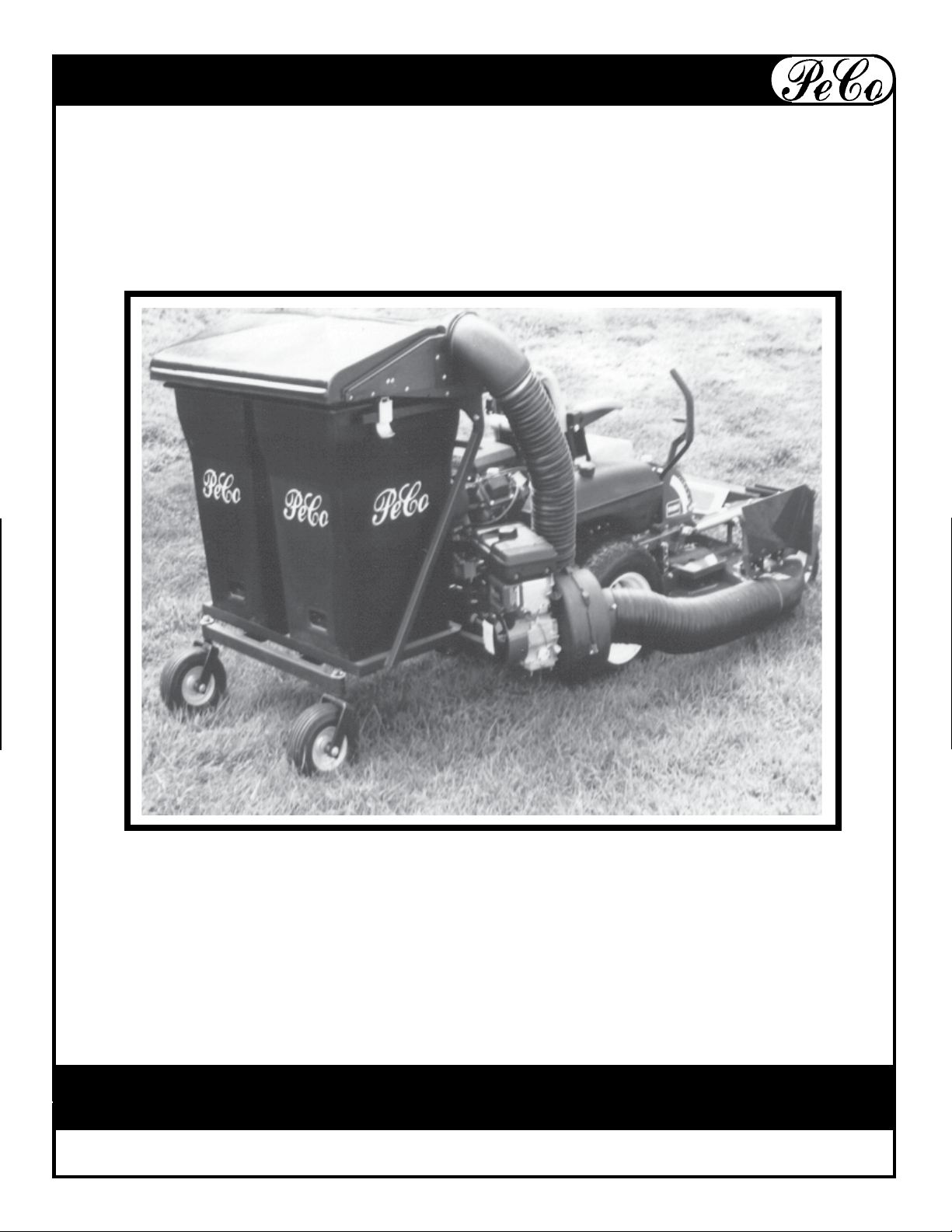
CONGRATULATIONS AND THANK YOU FOR BUYING THIS PECO LAWN VACUUM.
Your new PeCo Vac has been engineered and manufactured to PeCo's high standards for
safety, quality and dependability and ease of operations.
Sav e This Manual F or Future Refer ence
MODEL 37641401 - 04
PeCo
Page 2

WARRANTY
PeCo Limited Warranty for New Products
A. WHAT IS WARRANTED?
PeCo extends the following
warranties to the original
purchaser of each new PeCo
consumer product subject to
the following limitations.
1. PRODUCT WARRANTY.
Any part of any consumer
product, which is defective
in material or workmanship
as delivered to the purchaser
will be repaired or replaced,
as PeCo elects, without
charge for parts or labor, if
the defect appears within 12
months from the date of
delivery of the product to the
original purchaser. ALL
DEFECTIVE PARTS MUST
BE RETURNED TO PeCo
FOR INSPECTION TO
DETERMINE VALIDITY OF
WARRANTY CLAIMS.
Freight and mailing charges
will be borne by the
customer.
2. PARTS REPLACED
DURING WARRANTY.
Any new PeCo part which is
furnished in performance of
this warranty and is
defective in material or
workmanship as delivered to
the purchaser will be
repaired or replaced, as
PeCo elects, without charge
if the defect appears within
90 days from the date of
installation of such part or
before the expiration of the
original warranty period,
whichever is later.
B. SECURING WARRANTY
ADJUSTMENTS
Damaged or broken parts other
than engines or batteries, must be
returned to PeCo, Inc., P.O. Box
1197, Arden, NC 28704 bef ore any
warranty adjustment can be
authorized. At the time of
requesting warranty adjustment,
the purchaser must present
evidence of the date of delivery
of the product. The purchaser
shall pay any charge for
transporting the product to and
from Arden, NC.
C. ITEMS NOT COVERED BY
PeCo W ARRANTY.
Engines and batteries attached to
PeCo products are covered under
a separate warranty by the
respective manufacturer.
D. UNAPPROVED ALTERATION
OR MODIFICATION.
All obligations of PeCo, Inc. under
this warranty shall be terminated
if products are altered or modified
in ways not approved by PeCo,
Inc.
E. ACCIDENTS AND NORMAL
MAINTENANCE.
The warranty covers only
defective material and
workmanship. It does not cover
depreciation or damage caused
by normal wear, accident,
improper use or abuse of
products. The cost of normal
maintenance and normal
replacement of service items such
as belts, cutting blades, hoses,
etc., which are not defective shall
be paid for by the purchaser.
F. NO REPRESENTATIONS
ADDITIONAL WARRANTIES,
DISCLAIMER.
Neither PeCo, Inc. nor any company
affiliated with it makes any
warranties, representations or
promises as to the quality of
performance of its products other
than those set forth herein. Except
as described above, PeCo, Inc.
makes no other warranties AND
SPECIFICALLY DISCLAIMS ANY
AND ALL IMPLIED WARRANTIES
OF FITNESS AND
MERCHANTABILITY.
G. ANY MACHINE USED FOR
RENTAL OR COMMERCIAL
PURPOSES GUARANTEED FOR 45
DAYS FROM DATE OF ORIGINAL
SALE ONLY.
H. REMEDIED EXCLUSIVE.
The only remedies the purchaser
has in connection with the breach
or performance of any warranty on
PeCo, Inc. consumer products are
set forth above. In no event will
PeCo be liable for special incidental
or consequential damages.
I. NO DEALER WARRANTY.
The selling dealer makes no
warranty on his own on any item
warranted by PeCo, Inc. unless he
delivers to purchaser a separate
written warranty certificate
specifically warranting the item.
The dealer has no authority to make
any representation or promise on
behalf of PeCo or to modify the
terms of limitations of this warranty
in any way.
2
MODEL 37641401 - 04
PeCo
Page 3
SAFETY
Outdoor Power Equipment Institute Recommendations
WARNING TO PURCHASERS OF INTERNAL COMBUSTION ENGINE EQUIPPED
MACHINERY OR DEVICES IN THE STATE OF CALIFORNIA:
The equipment which you have purchased does not have a spark arrester muffler. If this
equipment is to be used on any forest covered and brush covered land or grass covered
unimproved land in the state of California, the law requires that a spark arrester muffler be
installed and be in effective working order. The spark arrester must be attached to the
exhaust system and comply with Section 4442 of the California Public Resources Code.
1. Read the owner's manual carefully and familiarize yourself with the proper use of your attachment.
Do not allow anyone who is not acquainted with the
Safety Instructions to use your attachment.
2. Know the controls and how to stop quickly.
READ THE OWNER'S MANUAL!
3. Do not allow children to operate the vehicle. Do
not allow adults to operate it without proper instruction.
4. Be especially watchful of children and pets
darting into the area while operating.
5. Keep your eyes and mind on your tractor while
mowing or operating your attachment. Don't let
others distract you.
6. Do not attempt to operate your tractor or mower
when not in the driver's seat.
WARNING!
NEVER operate the mower unless the discharge
guard and either the deflector assembly or the
vacuum collector adapter are fastened securely in
place.
7. Always stop Vac engine when emptying the
container.
8. Stop tractor and vac engines and remove spark
plug wire before removing or replacing hose, boot,
blower cone or performing any maintenance.
9. Mow up and down the face of slopes (not steeper
than 10 degrees); never across the face of the slope.
10. It is recommended that the container be kept
only half full when negotiating any slopes. Start
mowing on slopes when the container is empty.
11. Inspect your lawn and remove any foreign objects before mowing. Never deliberately run mower
across any foreign object.
12. Wear ear protection if noise level is offensive.
WARNING!
Do not work around the mower deck boot or the
blower area until you are certain that the mower
blades and the blower fan have stopped rotating.
WARNING!
To avoid serious injury, perform maintenance on
the vacuum collector ONLY AFTER STOPPING THE
TRACTOR ENGINE AND WAITING FOR ALL MOVING PARTS TO COME TO A COMPLETE STOP. Set
the parking brake. Always remove the ignition key
before beginning the
maintenance
3
MODEL 37641401 - 04
For your personal safety, ALWAYS mow UP and
DOWN the face of slopes and NEVER across the
face. NEVER attempt to mow excessively steep
slopes and use caution when turning on any
slope.
WARNING!
PeCo
Page 4
ASSEMBLY
STEP 1:
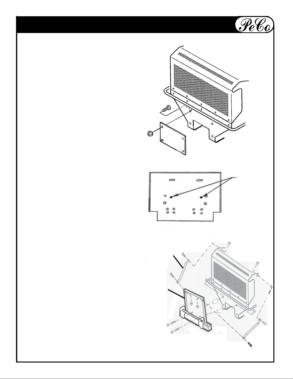
Remove plate on rear of mower as shown.
Redrill top two holes for a 3/8"-16 hex bolt
to mount Mount Frame onto mower frame.
MOWER
FRAME
FIG. 1-1
DESIGNATION OF
HOLES ON THE
MOUNT PLATE
STEP 2:
Use (2) 3/8"-16 x 2" (#K1208) and (2)
3/8"-16 flange nuts (#K1215) to secure
Mount Plate (A) to mower frame. Use (2)
1" spacers (#S0138) between Mount
Plate (A) and mower frame. Place (1)
Bracket (B) on each side of Mount Plate
(A). Use (1) 3/8"-16 x 3/4" hex bolt (#K1190)
and (1) 3/8"-16 flange nut (#K1215) to
mount each Bracket. Use existing bolts
from mower frame to mount Bracket (B)
to mower. Use figure 1-1 to place bolts.
HOLES TO
MOUNT TO
TRACTOR
B
A
4
MODEL 37641401 - 04
PeCo
Page 5
ASSEMBLY
STEP 3:
A
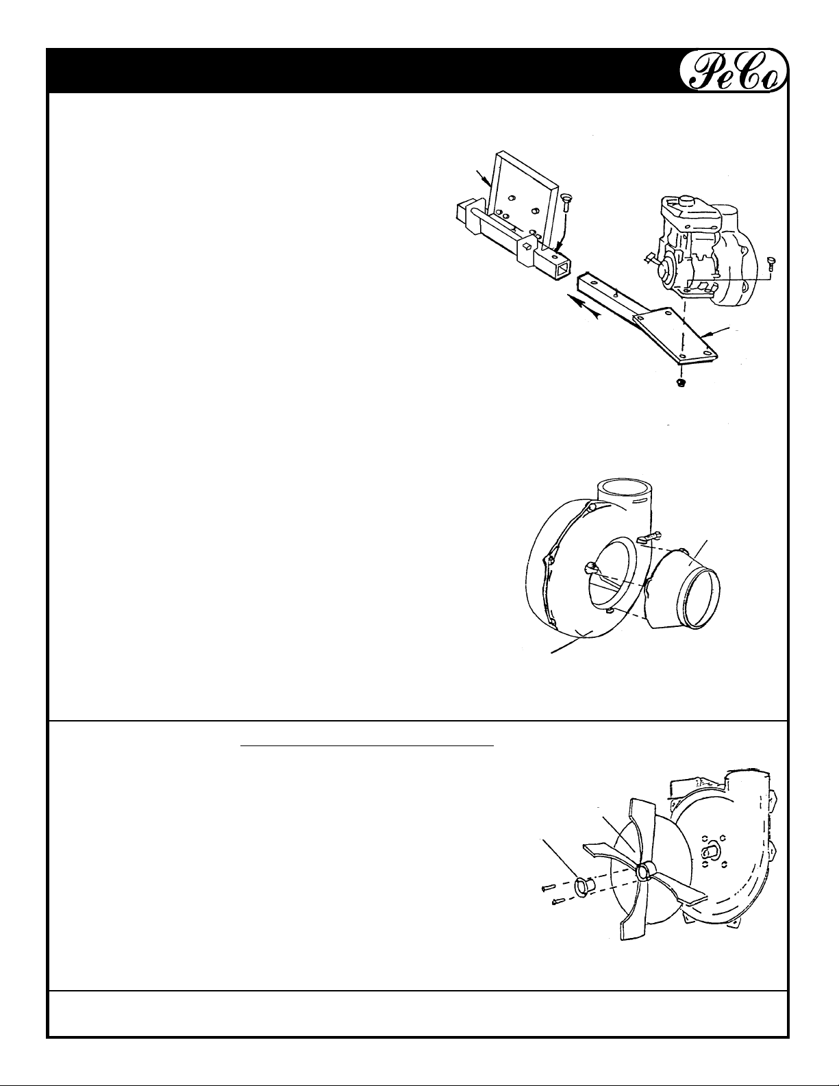
Slide Engine Mount Arm (B) into the receiver
on the Mount Plate (A) and fasten by
dropping in ball pin (#J0248). Place Engine/
Blower Assembly onto Engine Mount Arm (B)
and fasten with (4) 5/16"-18 x 1 1/2 hex bolts
(#K1157) and (4) 5/16"-18 flange nuts. Tighten
nuts and bolts.
B
STEP 4:
The ears of the Cone (A) should fit underneath
the two threaded bosses on the Blower Face (B).
Secure with (2) 5/16"-18 x 2" cone bolts.
TIGHTEN CONE BOLTS BEFORE EACH USE!
Impeller Blade Replacement
To remove: Remove hex bolts from hub then screw the bolts
into threaded holes to remove old blade.
(This will push the impeller off the hub.) If the
impeller is stuck on, hit the base of the impeller
between each vein with a hammer then try the
bolts again.
To replace: Place tapered bushing (A) into hub (B) and align
non-threaded holes with the holes in the hub.
Secure with two 1/4" x 1" hex bolts. Torque to 15 ft. lbs.
A
B
B
A
5
MODEL 37641401 - 04
PeCo
Page 6
PARTS LIST
REF. NO. PART NO. DESCRIPTION QTY.
1 B3749 BOOT PLATE 1
2 ******* BOOT (SPECIFY DECK SIZE) 1
3 J6006 7"- 8" HOSE CLAMPS 2
4 ******* 42" LOWER HOSE 1
5 ******* BLOWER CONE 1
6 ******* ENGINE/BLOWER/BLADE ASSEMBLY 1
E4052A BLOWER HOUSING
D4002 5HP BRIGGS & STRATTON ENGINE
A0645 4 BLADE IMPELLAR W/ S4311 BUSHING
W/ 3/4" SHAFT
D1016 6HP KOHLER ENGINE
A0914 4 BLADE IMPELLAR W/ S4302 BUSHING
W/ 1" SHAFT
7 J6011 5"- 6" HOSE CLAMPS 2
8 ******* 6X32" UPPEER HOSE 1
9 ******* INLET 1
10 A0394 HARDTOP ASSEMBLY 1
11 A0155 BASE FRAME ASSY 1
12 A0907 (OPTIONAL) WEIGHT ASSEMBLY 1
14 A0930 MOUNT PLATE ASSEMBLY 1
16 A0751 ENGINE MOUNT ASSEMBLY 1
17 B1941 INSIDE INLET PLATE 1
18 B1926 OUTSIDE RETAINING PLATE 1
19 J0316 GAS STRUT 2
20 A0021 RIGHT HAND HINGE PLATE ASSEMBL Y 1
21 A0022 LEFT HAND HINGE PLATE ASSEMBLY 1
22 A0236 LATCH ASSEMBLY 2
23 A08216 HARDWARE BAG 1
24 V2002 7 CU. FT. CANISTER 2
25 A0921 CASTER ASSEMBLY 2
26 A0916 HITCH ASSEMBLY 1
6
MODEL 37641401 - 04
PeCo
Page 7

EXPLODED VIEW MODEL 37641402
16
14
22
10
11
22
17
9
18
19
21
20
8
7
6
12
26
5
25
24
1
2
4
7
MODEL 37641401 - 04
3
PeCo
Page 8
ASSEMBLY
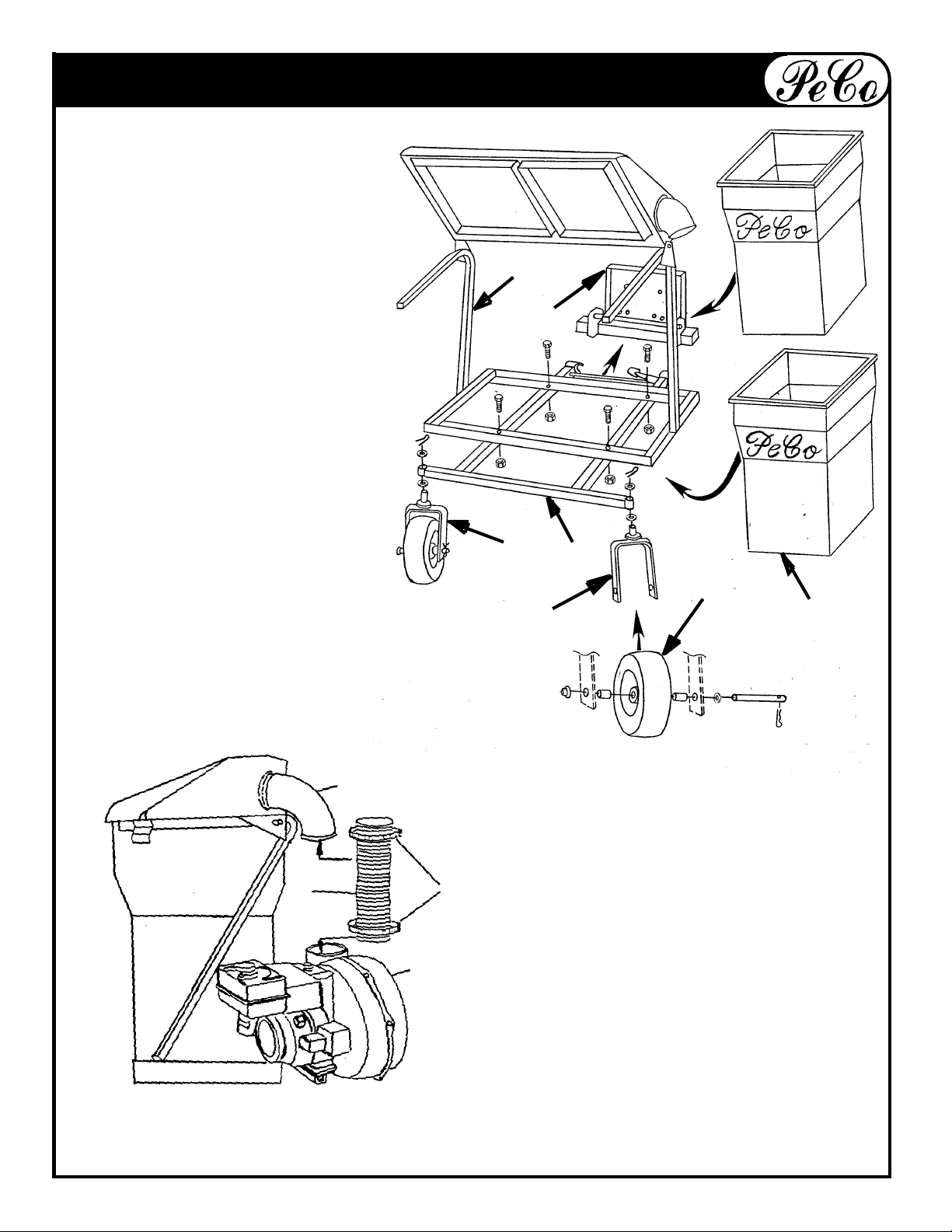
STEP 5:
Attach Wheel (A) to Caster
Fork (B) by using (1) axle (B4236),
(1) flat washer (K0017), (2) spacers
(S3315), (1) push nut (K0199), and
(1) cotter pin (K0085). Next attach
assembled Caster (C) to Hitch (D)
by using (2) 1" washers (K0064)
and (1) cotter pin (K0089). Attach
Hitch Assembly (D) to Main Frame
(E) by using (4) 3/8"-16 x 2 1/2" hex
bolts and (4) 3/8"-16 flange nuts.
Slide arm to open jaws on Hitch
(D) and attach to the Mount Plate
(F) and lock jaws. Place (2) 7 cu.
ft. canisters (G) into the Main
Frame (E) and close lid.
C
E
F
D
A
G
B
B
D
A
STEP 6:
Place Clamps (A) over each end of
6" Hose (B). Attach one end of hose
onto Blower Housing (C). Attach free
end of hose over Inlet (D).
TIGHTEN CLAMPS!
C
8
MODEL 37641401 - 04
PeCo
Page 9
ASSEMBLY
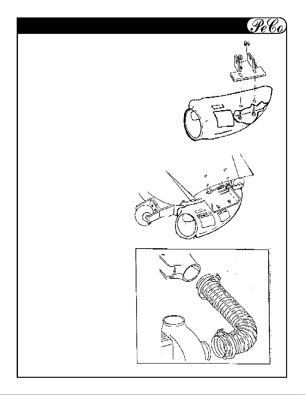
STEP 7:
Attach Boot Retainer to Boot with 3/8" x 1"
carriage bolts and 3/8" flange nuts as shown.
TIGHTEN NUTS AND BOLTS!
STEP 8:
Lift mower deflector and hang Boot
Plate as shown.
STEP 9:
Place Clamp over each end of Lower
Hose. Attach one end of hose over
the Blower Cone. Tighten Clamp.
Slide free end of hose over Boot and
tighten clamps.
9
MODEL 37641401 - 04
PeCo
Page 10
MAINTENANCE
Your Lawn Vac was designed and built to provide years of service with only minor care. Certain
tasks however must be performed to keep it in good operating condition and to avoid costly
repairs. This section describes and provides procedures for the necessary care of the Lawn
Vac.
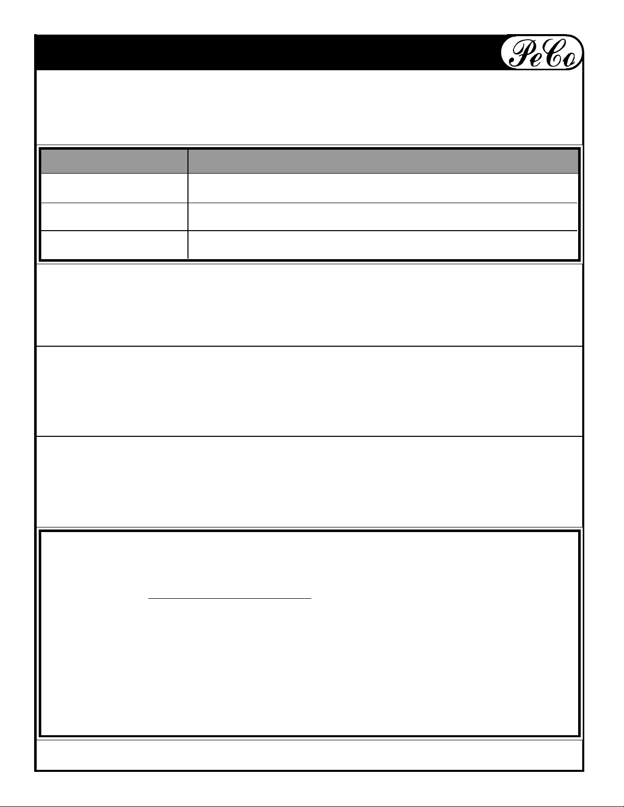
SCHEDULED CARE
CARE REQUIRED
Before Each Use
After Each Use
Every 10 Hours
Check engine oil.
Check all hose connections.
Clean Collector Box, hoses and engine of all grass and dirt.
Check that all screws, nuts, bolts, pins, etc. are present and
secure.
Storage
Never store your Lawn Vac with a full or partially filled container; decaying grass and leaves
may constitute a fire hazard if left too long. Never leave your vac exposed to the elements.
While the metal parts are protected with a quality paint, the engine and other unprotected parts
may deteriorate if left exposed to rain or snow.
Emptying The Lawn Vac
When the collector becomes full, the blower tone will change. In order to empty the container
- Release the back door by moving the dump handle on the left hand side of the container.
Release the door, push back on the container and the debris falls out. When empty, pull the
box forward; move the dump handle in to properly close the rear door.
Service
PeCo Lawn Vac Owners should record the name and telephone number of their tractor
dealer. Your dealer will be happy to supply replacement parts, accessories and do any
service or repairs to your lawn vac. If for some reason your dealer is unable to service your
lawn vac or supply replacement parts, contact PeCo and include the following information:
Tractor Model: __________________________________ Year of Mfg. _________________
Deck Size: _____________________________________
PeCo Vac Model: ________________________
Vac Serial Number: _______________________________
Date of Purchase: _____ /_______ /________
Dealer Name: _________________________________________________________________
Dealer's City: ___________________________ State: ______________ Zip: __________
Dealers Phone Number: _______________________________
10
MODEL 37641401 - 04
PeCo
Page 11
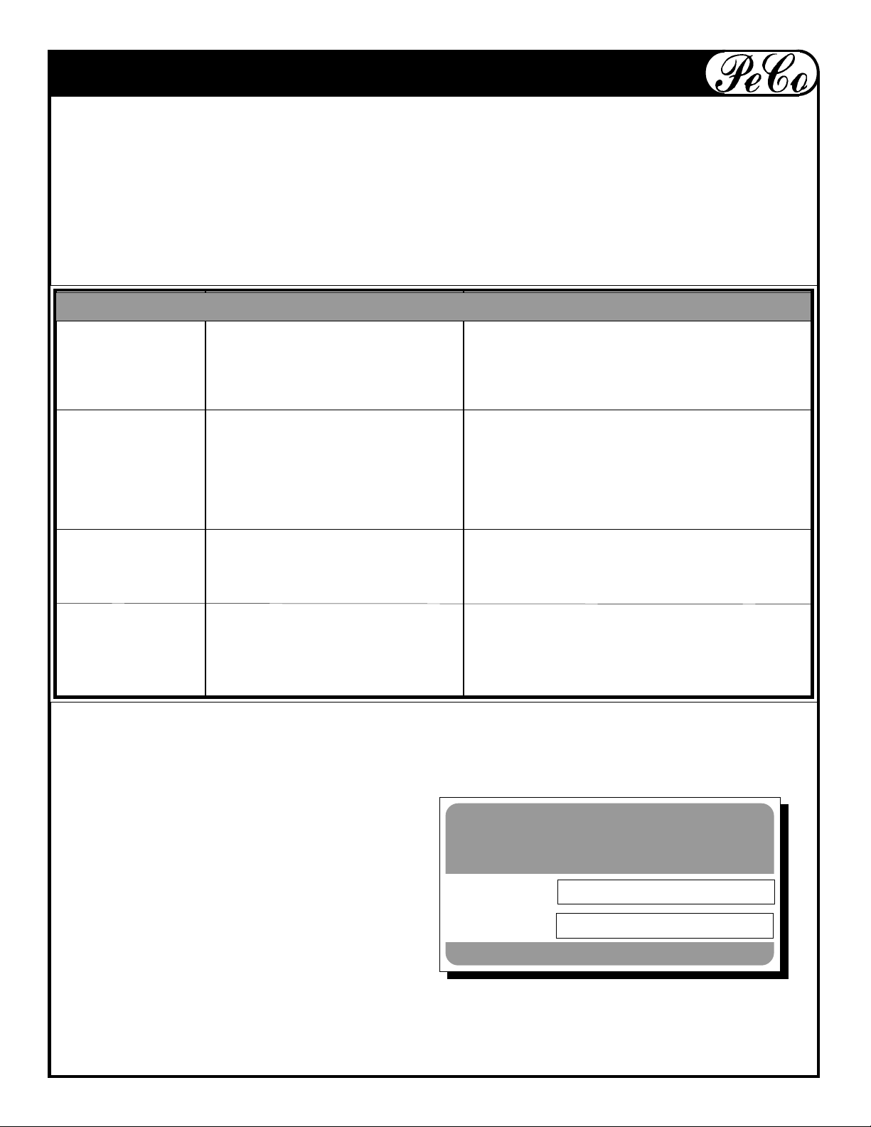
TROUBLE SHOOTING
Diagnostic Procedures
Trouble shooting procedures are provided in the chart below. To use these procedures,
first locate the problem description that best describes the trouble that you have encountered. Check the possible causes one at a time in the list. Correct any problems that are
found and operate the vacuum collector again to verify that you have eliminated the problem.
DO NOT attempt any major repairs without first contacting your dealer.
PROBLEM CAUSE SOLUTION
Leaves and Grass 1. Engine speed too slow A. Run at full throttle.
not being picked 2. Ground speed too fast. B. Use lower gear
up completely. 3. Hose plugged. C. Check and tighten all hoses.
D. Unplug hose.
Hoses plug easily. 1. Grass or leaves too wet. A. Wait for drier conditions.
2. Grass too high. B. Reduce tractor ground speed/raise deck.
3. Container full. C. Empty container
4. Grass buildup in boot or D. Clean thoroughly.
under mower deck.
Vacuum Collector 1. Buildup on blower blades. A. Remove cone and clean blades.
blower vibrates 2. Bent or chipped blade. B. Contact your dealer or PeCo.
excessively.
Unit fails to fill box. 1. Engine speed too slow. A. Run at full throttle.
2. Buildup on inlet or screen B. Clean thoroughly.
3. Grass is too wet or long. C. Wait for dryer conditions.
OUTDOOR POWER EQUIPMENT
The Serial Number Plate is located
Model Number
on the aluminum box near the
dump handle.
Serial Number
Arden, North Carolina 28704
11
MODEL 37641401 - 04
PeCo
Page 12

P.O. Box 1197
Arden, North Carolina 28704
1-800-438-5823 or (828) 684-1234 fax-(828) 684-0858
email: [email protected]
MODEL 37641401 - 04
PeCo
 Loading...