

Page 1
Installation &
Operator’s Manual
Manuel d'installation
et d'utilisation
Manual de Instalación
y del Operario
Questions? Help is just a moment away!
Vous avez des questions? Vous n'avez pas
besoin d'aller loin pour trouver de l'aide!
¿Preguntas? ¡La ayuda está muy cerca!
Call: Home Generator Helpline
Appelez: Ligne Directe de GÉNÉRATRICE
LRÉSIDENTIELLE
Llame: Línea Directa de Generador de Hogar
1-800-743-4115 M-F 8-5 CT
BRIGGSandSTRATTON.com
Models 071014 & 071017 Part No. 198417GS Rev. - (08/15/06)
30A NEMA 1 / NEMA 3R
Switching Neutral
Manual Transfer Switch
Page 2

TABLE OF CONTENTS
2
TABLE OF CONTENTS
TABLE OF CONTENTS . . . . . . . . . . . . . . . . . . . . . . . 2
IMPORTANT SAFETY INSTRUCTIONS . . . . . . . . . . 3
INTRODUCTION . . . . . . . . . . . . . . . . . . . . . . . . . . . . 4
For the Home Owner . . . . . . . . . . . . . . . . . . . . . . 4
For the Installing Dealer/Contractor. . . . . . . . . . . 4
Owner Orientation . . . . . . . . . . . . . . . . . . . . . . . . 5
Installer Responsibilities . . . . . . . . . . . . . . . . . . . 5
Equipment Description . . . . . . . . . . . . . . . . . . . . 5
Generator Compatibility . . . . . . . . . . . . . . . . . . . . 5
INSTALLATION. . . . . . . . . . . . . . . . . . . . . . . . . . . . . . 6
Unpacking . . . . . . . . . . . . . . . . . . . . . . . . . . . . . . 6
Delivery Inspection . . . . . . . . . . . . . . . . . . . . 6
Mounting Guidelines . . . . . . . . . . . . . . . . . . . . . . 7
ESSENTIAL CIRCUIT ISOLATION . . . . . . . . . . . . . . 8
Power Wiring Interconnections . . . . . . . . . . . . 9-10
Inlet Box. . . . . . . . . . . . . . . . . . . . . . . . . . . . . 11-12
Connecting Cord Set . . . . . . . . . . . . . . . . . . 12
SYSTEM OPERATION . . . . . . . . . . . . . . . . . . . . . . . 13
Load Management. . . . . . . . . . . . . . . . . . . . . . . 13
SPECIFICATIONS . . . . . . . . . . . . . . . . . . . . . . . . . . 14
Model 071014 . . . . . . . . . . . . . . . . . . . . . . . 14
Model 071017 . . . . . . . . . . . . . . . . . . . . . . . 14
When Calling The Factory . . . . . . . . . . . . . . . . . 14
TROUBLESHOOTING . . . . . . . . . . . . . . . . . . . . . . . 15
SERVICE PARTS . . . . . . . . . . . . . . . . . . . . . . . . . . . 16
WARRANTY. . . . . . . . . . . . . . . . . . . . . . . . . . . . . . . 17
Copyright © 2006 Briggs & Stratton Power Products
Group, LLC. All rights reserved. No part of this
material may be reproduced or transmitted in any form
by any means without the express written permission
of Briggs & Stratton Power Products Group, LLC.
is a registered trademark of Briggs & Stratton
Corporation, Milwaukee, WI, U.S.A.
Page 3
IMPORTANT SAFETY INSTRUCTIONS
3
IMPORTANT SAFETY
INSTRUCTIONS
This is the safety alert symbol. It is used to
alert you to potential personal injury
hazards. Obey all safety messages that
follow this symbol to avoid possible injury
or death.
The safety alert symbol ( ) is used with a signal
word (DANGER, CAUTION, WARNING), a pictorial
and/or a safety message to alert you to hazards.
DANGER indicates a hazard which, if not avoided, will
result in death or serious injury. WARNING indicates a
hazard which, if not avoided, could result in death or
serious injury. CAUTION indicates a hazard which, if
not avoided, might result in minor or moderate injury.
NOTICE, when used without the alert symbol,
indicates a situation that could result in equipment
damage. Follow safety messages to avoid or reduce
the risk of injury or death.
The manufacturer cannot possibly anticipate every
possible circumstance that might involve a hazard.The
warnings in this manual, and the tags and decals
affixed to the unit are, therefore, not all-inclusive. If you
use a procedure, work method or operating technique
that the manufacturer does not specifically
recommend, you must satisfy yourself that it is safe for
you and others.You must also make sure that the
procedure, work method or operating technique that
you choose does not render the transfer switch unsafe.
SAVE THESE INSTRUCTIONS
• DO NOT touch bare wires or receptacles.
• DO NOT use transfer switch with worn, frayed, bare or
otherwise damaged wiring.
• DO NOT handle electrical cords while standing in water,
while barefoot, or while hands or feet are wet.
• If you must work around a unit while it is operating, stand
on an insulated dry surface to reduce shock hazard.
• DO NOT allow unqualified persons or children to operate
or service transfer switch.
• In case of an accident caused by electrical shock,
immediately shut down the source of electrical power and
contact local authorities. Avoid direct contact with the
victim.
Failure to properly ground transfer switch
can result in electrocution.
WARNING
• Use transfer switch only for intended uses.
• If you have questions about intended use, ask dealer or
contact Briggs and Stratton Power Products.
• DO NOT expose transfer switch to excessive moisture,
dust, dirt, or corrosive vapors.
• Remain alert at all times while working on this
equipment. NEVER work on the equipment when you are
physically or mentally fatigued.
• If connected devices overheat, turn them off and turn off
their circuit breaker/fuse.
Improper treatment of transfer switch can damage
it and shorten its life.
NOTICE
• Despite the safe design of the transfer switch, operating
this equipment imprudently, neglecting its maintenance or
being careless can cause possible injury or death.
Transfer Switch contains hazardous voltage
that can cause personal injury or death.
WARNING
• Licensed electrician must perform installation of transfer
switch.
• Follow all applicable federal, state and local codes,
standards and regulations.
Contact with live parts can cause electric
shock or burn.
WARNING
Page 4

INTRODUCTION
4
INTRODUCTION
Thank you for your purchase of this Briggs & Stratton
Switching Neutral Manual Transfer Switch. This transfer
switch is designed for use with generators equipped
with or without Ground Fault Circuit Interrupters (GFCI).
The switch disconnects the appropriate neutral circuit to
allow the GFCI to function properly.
This transfer switch is for use with optional home
standby systems which provide an alternate source of
electric power and to serve loads such as a gas
furnace, refrigeration and communication systems that,
when stopped during any power outage, could cause
discomfort, or the like. This product DOES NOT qualify
for emergency standby as defined by NFPA 70 (NEC).
Briggs and Stratton Power Products (BSPP) has made
every effort to provide for a safe, streamlined and costeffective installation. Each installation is unique, it is
impossible to know of and advise of all conceivable
procedures and methods by which installation might
be achieved. We do not know all possible hazards
and/or the results of each method or procedure. For
these reasons,
Only licensed electricians
should install transfer switches.
Installations must strictly comply with all
applicable federal, state and local codes,
standards and regulations.
Your BSPP Transfer Switch is supplied with this
combined “Installation and Operator’s Manual”. This is
an important document and should be retained by the
owner after the installation has been completed.
Every effort has been expended to make sure that the
information in this manual is both accurate and
current. However, the manufacturer reserves the right
to change, alter or otherwise improve the system at
any time without prior notice.
For the Home Owner
To help you make informed choices and communicate
effectively with your installation contractor(s),
Read and understand the
Owner Orientation Section of this manual
BEFORE
contracting or starting
your transfer switch installation.
To arrange for proper installation, contact the store at
which you purchased your BSPP Transfer Switch, your
dealer, or your utility power provider.
The Transfer Switch Warranty is V
OID
unless the system is installed by a
licensed electrical professional.
For the Installing Dealer/Contractor
• Check federal, state and local codes for questions
on installation.
• If you need more information about the transfer
switch, call 1-800-743-4115, between 8:00 AM and
5:00 PM CT.
Page 5

INTRODUCTION
5
Owner Orientation
The provided illustrations deplict typical circumstances
and are meant to familiarize you with the installation
options available with your transfer switch.
Local codes, appearance, and distances are factors
that must be considered when negotiating with an
installation professional.As the distance from the
existing electrical service increases, compensation in
wiring materials must be allowed for. This is necessary
to comply with local codes and overcome electrical
voltage drops.
The factors mentioned above will have a direct effect
on the overall price of your transfer switch
installation.
NOTE: Your installer must check local codes AND
obtain permits before installing the system.
Read and follow the instructions given in this manual.
Installer Responsibilities
• Read and observe the safety rules.
• Read and follow the instructions given in this
manual.
• Check federal, state and local codes, standards and
regulations.
• Ensure generator is not overloaded with selected
loads.
Equipment Description
This transfer switch is intended to operate electrical
loads found in normal residential installations. The load
is connected either to utility power (normal) or home
standby power (generator).
The manual transfer switch is equipped with two main
circuit breakers (“GENERATOR SUPPLY” and
“UTILITY SUPPLY”) and a mechanical interlock. The
“GENERATOR SUPPLY” circuit breaker connects
power from the generator to the load devices wired to
the manual transfer switch. The “UTILITY SUPPLY”
circuit breaker connects utility power from the
distribution panel to the loads wired to the manual
transfer switch. Each of these circuit breakers have an
isolated neutral that MUST be connected inside the
transfer switch.
The mechanical interlock allows the circuit breakers for
either the generator power “GENERATOR SUPPLY” or
the utility power “UTILITY SUPPLY” to be turned on to
provide power to the selected house loads. This
switching neutral manual transfer switch will not allow
utility line power and generator power to be connected
to a load device at the same time.
If utility line power is restored while generator power is
being used, there will be no effect on the generator or
transfer switch components. When utility power is
restored, follow the instructions in the section “System
Operation”.
Generator Compatibility
Only use a generator that is factory-equipped with a
NEMA L14-20R or NEMA L14-30R receptacle, shown
in Figures 9 and 10.
• NEVER connect transfer switch to any receptacle other
than those recommended as damage to connected
appliances may occur.
NOTICE
Page 6
INSTALLATION
6
INSTALLATION
Unpacking
Delivery Inspection
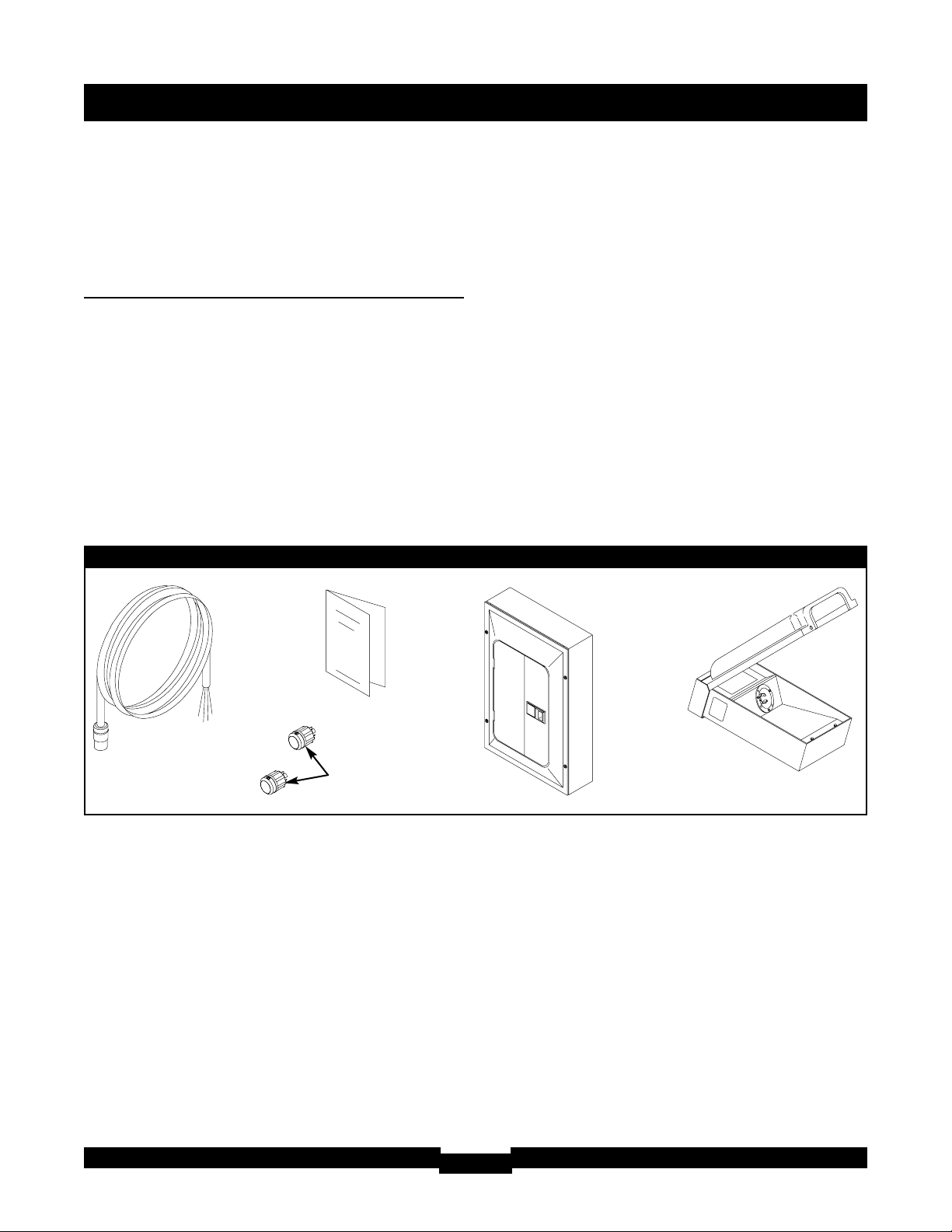
Remove the Transfer Switch components shown in
Figure 1 from the shipping carton.
The transfer switch is supplied ready for installation.
Inspect the switch and its attached components for any
shipping damage.
The inlet box is supplied ready to be wired. Inspect it,
the connection cord set, and the connecting plugs for
any damage. The installer will select and connect the
appropriate connection cord plug to match generator
receptacle.
IMPORTANT: If loss or damage is noted at time of
delivery, have the person(s) making delivery note all
damage on the freight bill and affix his signature under the
consignor's memo of loss or damage. If loss or damage is
noted after delivery, contact the carrier for claim
procedures. Freight damaged parts are not warranted.
Items Not Shipped with Transfer Switch:
The following items, required for system installation,
are not included and must be provided by the installer:
1. Tools required for installation
2. Anchors and screws to mount the transfer switch
components and conduit.
3. Conduit, fittings, wire nuts, and insulated copper
wire for connecting the transfer switch to the
outside inlet box and main distribution panel.
Inlet Box
Connecting Cord Set
Transfer Switch
(Model 071014 shown)
Manual
Connecting Plugs
Figure 1 — Transfer Switch Components
Page 7
Mounting Guidelines
The Model 071014 Switching Neutral Manual Transfer
Switch is enclosed in a NEMA Type 1 enclosure
suitable for indoor use ONLY.
The Model 071017 Manual Transfer Switch is enclosed
in a NEMA Type 3R enclosure suitable for
indoor/outdoor use.
Guidelines for mounting the Switching Neutral Manual
Transfer Switch include:
• Model 071017 Switching Neutral Manual Transfer
Switch must be installed with minimum NEMA 3R
hardware for conduit connections.
• Install switch on a firm, sturdy supporting structure.
• Ensure enclosure is level and plumb. This can be
done by placing washers between switch enclosure
and mounting surface.
• NEVER install switch where any corrosive substance
might drip onto enclosure.
• Protect switch at all times against excessive moisture,
dust, dirt, lint, construction grit and corrosive vapors.
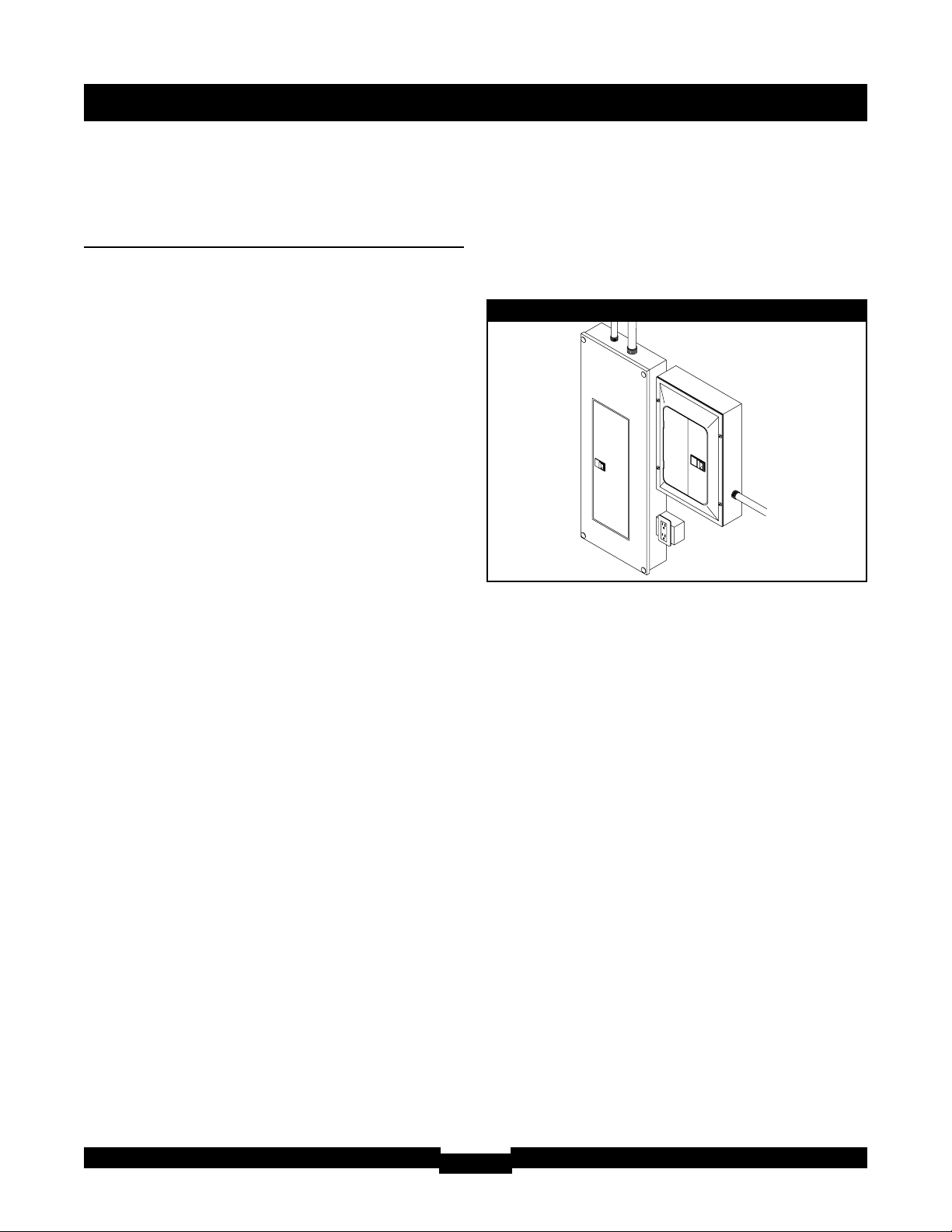
The typical installation of the Switching Neutral Manual
Transfer Switch is depicted in Figure 2. Discuss layout
suggestions/changes with the owner before beginning
the system installation process.
INSTALLATION
7
Switching
Neutral Manual
Transfer Switch
Main
Distribution
Panel
Figure 2 — Typical Switch Mounting
Model 071014 shown
Page 8
ESSENTIAL CIRCUIT
ISOLATION
Essential electrical loads are loads that will be powered
by the Home Generator System. Essential loads are
grouped together and wired into the transfer switch.
TO THE INSTALLER: Consult with Home
Generator System owner(s) to discuss their
selection of essential circuits, described in
generator operator’s manual.
DO NOT overload generator as described in generator
operator’s manual.
The Switching Neutral Manual Transfer Switch is
connected to the branch circuit side in the main
distribution panel.
All wiring must conform to federal, state and local
codes.
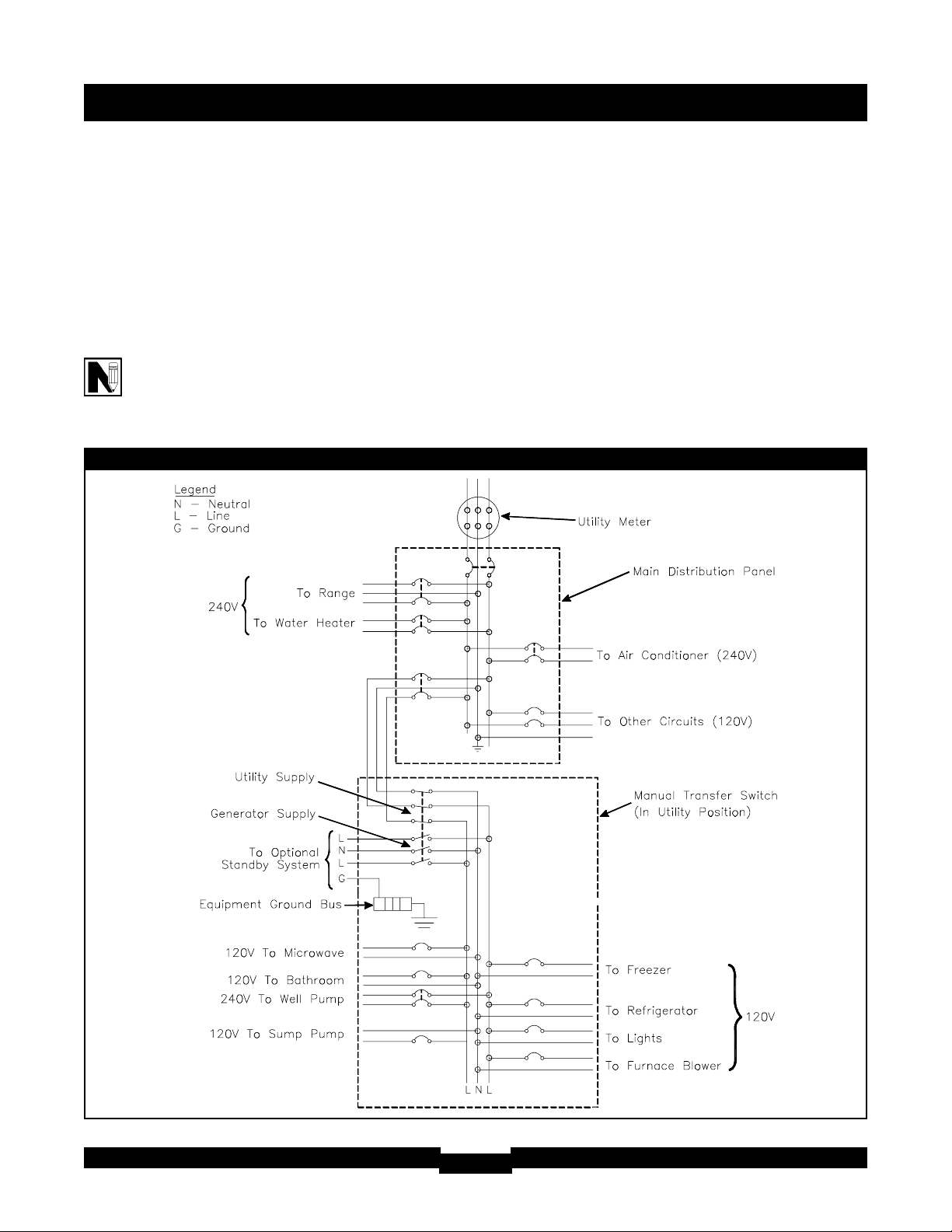
The illustration in Figure 3 depicts the Home
Generator System while utility is supplying
120/240 Volt, single-phase electrical service.
Figure 3 — Typical System Diagram with Essential Circuits
INSTALLATION
8
Page 9

INSTALLATION
9
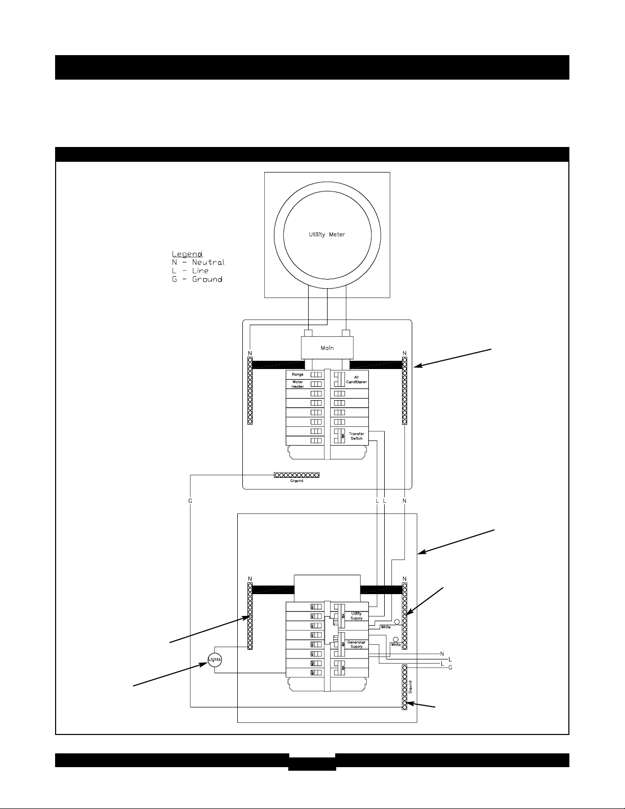
Power Wiring Interconnections
All wiring must be the proper size, properly supported
and protected by conduit. Ensure all power is
disconnected during installation.
Complete connections between the inlet box, main
distribution panel and the transfer switch per Figure 4
on the next page.
1. Connect utility feeder from two pole 50 Amp
branch circuit breaker in main distribution panel, to
transfer switch 50 Amp breaker marked “Utility
Supply”.
2. Connect main distribution panel neutral to transfer
switch 50 Amp breaker neutral marked “Utility
Supply”. DO NOT connect to neutral or ground bus
in transfer switch.
3. Connect main distribution panel equipment ground
to equipment ground bus in transfer switch.
4. Connect generator feeder from receptacle in inlet
box to transfer switch 30 Amp breaker marked
“Generator Supply”.
5. Connect generator neutral from receptacle in inlet
box to transfer switch 30 Amp breaker neutral
marked “Generator Supply” DO NOT connect to
neutral or ground bus in transfer switch.
6. Connect generator equipment ground from
receptacle in inlet box to transfer switch ground
bus.
IMPORTANT: Connecting the transfer switch neutral
bus to ground will trip the generator GFCI. DO NOT
connect the transfer switch neutral bus to ground.
7. Connect all branch circuit breakers to appropriate
essential circuits, including line and neutral circuit
conductors.
8. Tighten all wire connections and fasteners to
proper torque.
NOTE: Utility and Generator branch circuit breakers in
transfer switch are specially designed to disconnect
appropriate neutral circuits during operation. This
feature allows the use of Ground Fault Circuit
Interrupter devices on generators when installed
correctly.
Page 10
INSTALLATION
10
Figure 4 — A Typical Installation Diagram for Transfer Switch
Neutral Bus
Neutral Bus
To Inlet Box
Ground Bus
Typical 120V
Essential Load
Main Distribution Panel
Transfer Switch
Page 11
INSTALLATION
11
Inlet Box
Installation must strictly comply with all applicable
federal, state and local codes when installing the
generator inlet box provided with this system.
1. Locate and mount inlet box on an outside wall as
close as possible to transfer switch. However,
consider household air intake ducting when when
locating generator and inlet box.
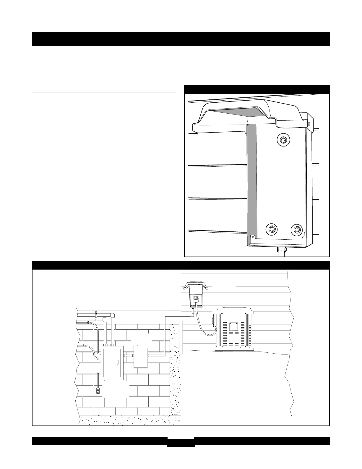
A typical transfer switch complete installation is
depicted in Figure 5.
2. Remove inlet box inner panel. Mount inlet box on
an outside wall (Figure 6).
3. Run appropriately sized conduit from transfer
switch to inlet box. Anchor all boxes, conduit, and
fittings.
Figure 6 — Inlet Box Installation
Figure 5 — A Typical Completed Transfer Switch Installation
Inlet Box
Transfer
Switch
Main
Distribution
Panel
Page 12
INSTALLATION
12
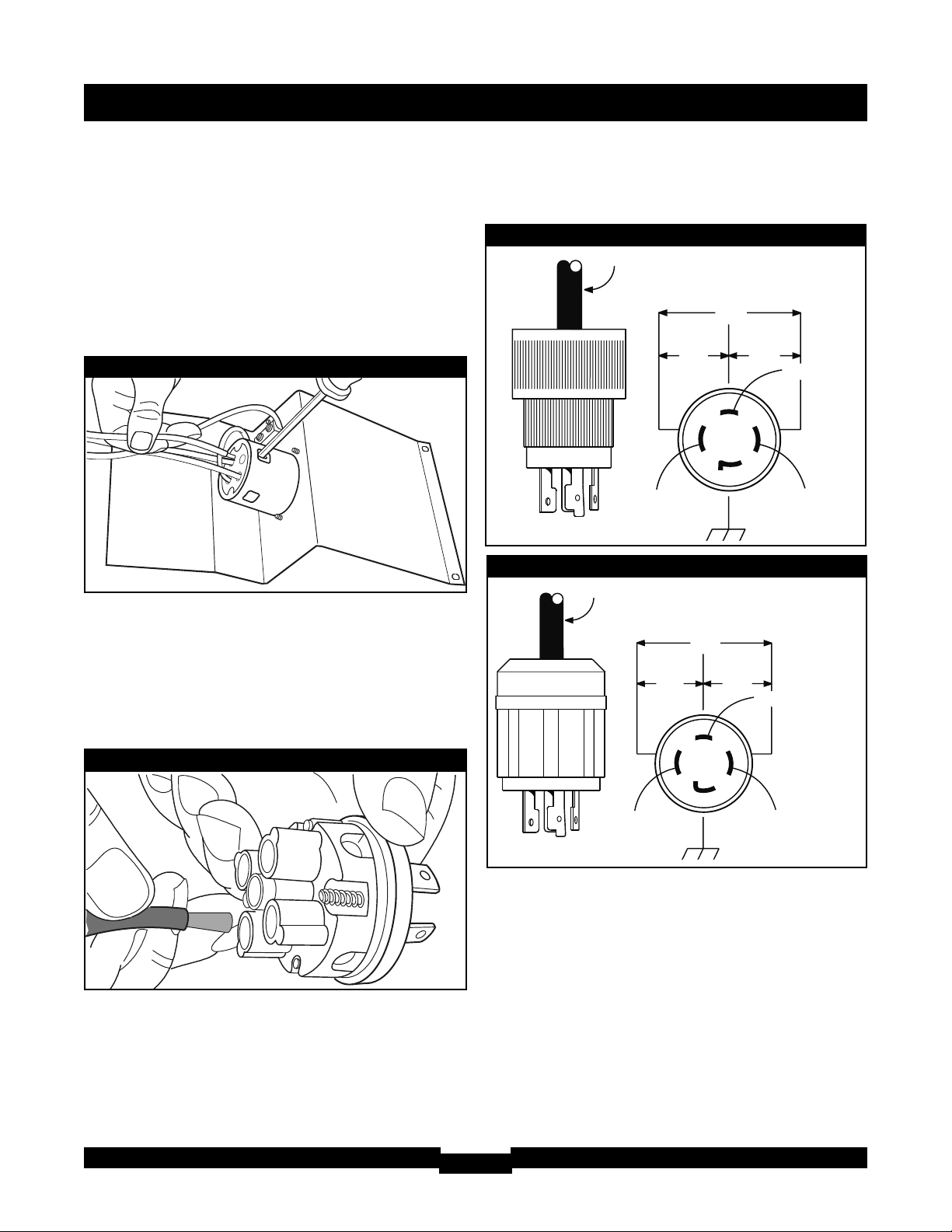
4. As shown in Figure 7, cut, strip, and connect each
wire to the appropriate terminal on the locking
receptacle on the inlet box inner panel. Use the
schematic affixed to the inside of the inlet box to
make proper wire connections. When all
connections have been made, reinstall the inlet
box inner panel.
Connecting Cord Set
From the two 120/240 Volt connection plugs supplied
with the transfer switch, select the one that mates to
the generator. Referring to the image in Figure 8 and
the schematic in Figure 9 or Figure 10 that applies to
the connector being used, properly attach the plug to
the pigtail end of the connecting cord set.
Figure 9 — 20A Cord Set Connector
4-Wire Cord Set
240V
120V
120V
W (Neutral)
X (Hot)
Y (Hot)
NEMA L14-20
Ground (Green)
Figure 10 — 30A Cord Set Connector
4-Wire Cord Set
240V
120V
120V
W (Neutral)
X (Hot)
Y (Hot)
NEMA L14-30
Ground (Green)
Figure 8 — Receptacle Connection
Figure 7 — Inlet Box Connections
Page 13
OPERATION
13
SYSTEM OPERATION
Load Management
The number of circuits that can be operated
simultaneously during a utility failure will depend on the
wattage capacity of your generator. Most optional
standby system generators do not have the
capacity to handle loads on all transfer switch
circuits at the same time.
Review the load management plan developed with the
installer. It may be necessary to selectively turn on and
off certain loads while using generator power so that
necessary appliances can be operated.
To transfer from utility power to generator power:
1. Align female socket of connecting cord set with
inlet box receptacle’s mating male prongs, as
shown in Figure 11. Push cord set connector in and
twist clockwise to lock.
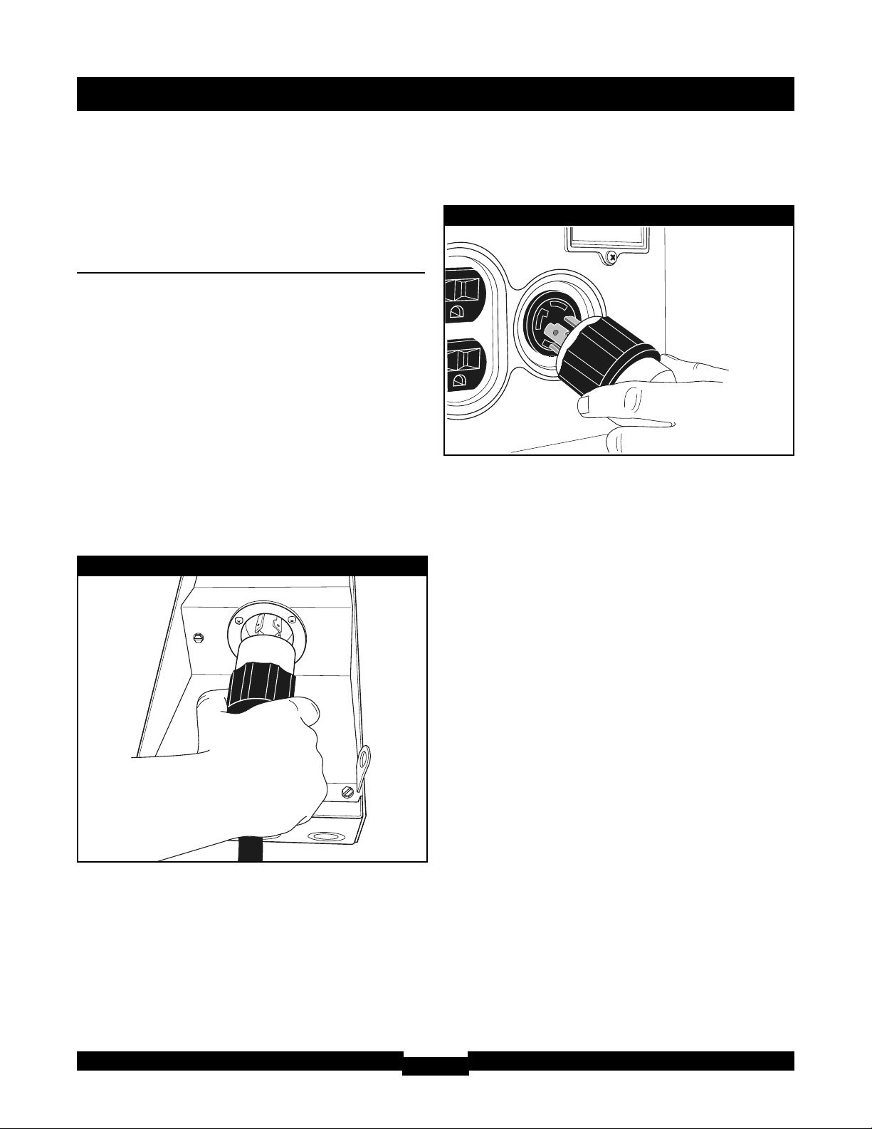
2. Align male prongs on other end of cord set with
mating female terminals of generator’s 240V
receptacle, as shown in Figure 12. Push in
connector and twist clockwise to lock.
3. Ensure generator is outdoors as described in
generator operator’s manual.
4. Start generator following instructions given in the
generator operator’s manual.
5. Turn OFF breaker labeled “UTILITY SUPPLY” in
transfer switch.
6. Turn OFF all branch circuit breakers in transfer switch.
7. Slide mechanical interlock in transfer switch and turn
“GENERATOR SUPPLY” breaker to ON position.
8. Turn ON branch circuit breakers one at a time
following your load management plan developed
with installer. DO NOT overload generator as
described in generator operator’s manual.
To transfer from generator power back to utility
power:
1. Turn OFF breaker labeled “GENERATOR
SUPPLY” in transfer switch.
2. Turn OFF all branch circuit breakers in transfer switch.
3. Slide mechanical interlock in transfer switch and
turn “UTILITY SUPPLY” breaker to ON position.
4. Turn ON branch circuit breakers one at a time.
5. Shut off generator following instructions given in
generator operator’s manual.
6. Disconnect connecting cord set from generator
and inlet box.
IMPORTANT: ALWAYS unplug cord when not in use
and store INDOORS.
Figure 11 — Inlet Box Connection
Figure 12 — Align Connectors at Generator
Typical Generator
Panel Shown
Page 14

14
SPECIFICATIONS
SPECIFICATIONS
UL® 1008 Listed Transfer Switch
Model 071014
Enclosure . . . . . . . . . . . . . . . . . . . . . . . . . . . .NEMA 1
Utility Supply Circuit Breaker Rating . . . . . . .50 Amps
Generator Supply Circuit Breaker Rating . . .30 Amps
Rated AC Voltage . . . . . . . . . . . . . . . . . . . . .250 Volts
Poles . . . . . . . . . . . . . . . . . . . . . . . . . . . . . . . . . . . . .2
Fault Current Rating . . . . . .10,000 RMS Symmetrical
Amperes
Weight . . . . . . . . . . . . . . . . . . . . . . . . . . . . . . . .27 lbs.
UL® 1008 Listed Transfer Switch
Model 071017
Enclosure . . . . . . . . . . . . . . . . . . . . . . . . . . .NEMA 3R
Utility Supply Circuit Breaker Rating . . . . . . .50 Amps
Generator Supply Circuit Breaker Rating . . .30 Amps
Rated AC Voltage . . . . . . . . . . . . . . . . . . . . .250 Volts
Poles . . . . . . . . . . . . . . . . . . . . . . . . . . . . . . . . . . . . .2
Fault Current Rating . . . . . .10,000 RMS Symmetrical
Amperes
Weight . . . . . . . . . . . . . . . . . . . . . . . . . . . . . . . .34 lbs.
When Calling the Factory
Before contacting Briggs and Stratton Power Products
regarding service or repair of this transfer switch,
obtain the Model Number from the unit data decal
located on or inside the case.
To contact Briggs and Stratton Power Products call
1-800-743-4115, between 8:00 AM and 5:00 PM CT.
Page 15

TROUBLESHOOTING
15
Problem Cause Solution
Generator is running, but no AC
output is available.
1. Generator circuit breaker is
open.
2. Poor connection or defective
cord set.
3. Connected device is bad.
4. Fault in generator.
1. Reset circuit breaker.
2. Check and repair.
3. Select a different appliance or
load that is in good condition.
4. Contact authorized service
center.
Generator runs good but bogs
down when loads are connected.
1. Short circuit in a connected
load.
2. Generator is overloaded.
1. Disconnect shorted electrical
load.
2. See “Load Management” on page
13.
Appliances don’t work after utility
power comes back on.
1. Transfer switch in GENERATOR
position.
2. Circuit breaker in main
distribution panel is open.
1. Set switch to UTILITY position.
2. Reset circuit breaker in main
distribution panel.
GFCI breaker in generator control
panel trips.
1. Ground fault in connected load.
2. Defective GFCI device.
3. Neutral bonded to ground in
transfer switch.
1. Remove load with fault.
2. Contact authorized service
center.
3. Contact authorized service
center.
TROUBLESHOOTING
Page 16

SERVICE PARTS
16
TRANSFER SWITCH SERVICE PARTS
MODEL 071014 (NEMA 1)
Part # Description
198414GS SWITCH, MNL, Transfer, NEMA 1
B3298GS BOX, Connection, 30A
198415GS CORDSET, 125/250V, 30A
43438GS PLUG, 125/250V, 30A, 4P Locking
43483GS PLUG, 250V, 20A, 4P
198417GS MANUAL, Operator’s
MODEL 071017 (NEMA 3R)
Part # Description
201031GS SWITCH, MNL, Transfer, NEMA 3R
B3298GS BOX, Connection, 30A
198415GS CORDSET, 125/250V, 30A
43438GS PLUG, 125/250V, 30A, 4P Locking
43483GS PLUG, 250V, 20A, 4P
198417GS MANUAL, Operator’s
Page 17

BRIGGS & STRATTON POWER PRODUCTS GROUP, LLC TRANSFER SWITCH OWNER WARRANTY POLICY
LIMITED WARRANTY
Briggs & Stratton Power Products Group, LLC will repair or replace, free of charge, any part(s) of the equipment that is defective
in material or workmanship or both. Transportation charges on product submitted for repair or replacement under this warranty
must be borne by purchaser.This warranty is effective for the time periods and subject to the conditions stated below. For
warranty service, find the nearest Authorized Service Dealer in our dealer locator map at BRIGGSandSTRATTON.com.
THERE IS NO OTHER EXPRESS WARRANTY. IMPLIED WARRANTIES, INCLUDING THOSE OF MERCHANTABILITY AND
FITNESS FOR A PARTICULAR PURPOSE, ARE LIMITED TO ONE YEAR FROM PURCHASE, OR TO THE EXTENT
PERMITTED BY LAW ANY AND ALL IMPLIED WARRANTIES ARE EXCLUDED. LIABILITY FOR INCIDENTAL OR
CONSEQUENTIAL DAMAGES ARE EXCLUDED TO THE EXTENT EXCLUSION IS PERMITTED BY LAW. Some states or
countries do not allow limitations on how long an implied warranty lasts, and some states or countries do not allow the exclusion
or limitation of incidental or consequential damages, so the above limitation and exclusion may not apply to you. This warranty
gives you specific legal rights and you may also have other rights which vary from state to state or country to country.
3 years
None
Consumer Use
Commercial Use
The warranty period begins on the date of purchase by the first retail consumer or commercial end user, and continues for the period
of time stated in the table above. “Consumer use" means personal residential household use by a retail consumer. “Commercial use"
means all other uses, including use for commercial, income producing or rental purposes. Once equipment has experienced
commercial use, it shall thereafter be considered as commercial use for purposes of this warranty. Equipment used for prime power
in place of utility are not applicable to this warranty.
NO WARRANTY REGISTRATION IS NECESSARY TO OBTAIN WARRANTY ON BRIGGS & STRATTON PRODUCTS. SAVE YOUR
PROOF OF PURCHASE RECEIPT. IF YOU DO NOT PROVIDE PROOF OF THE INITIAL PURCHASE DATE AT THE TIME
WARRANTY SERVICE IS REQUESTED, THE MANUFACTURING DATE OF THE PRODUCT WILL BE USED TO DETERMINE THE
WARRANTY PERIOD.
ABOUT YOUR WARRANTY
We welcome warranty repair and apologize to you for being inconvenienced. Any Authorized Service Dealer may perform warranty
repairs. Most warranty repairs are handled routinely, but sometimes requests for warranty service may not be appropriate. For
example, warranty service would not apply if equipment damage occurred because of misuse, lack of routine maintenance, shipping,
handling, warehousing or improper installation. Similarly, the warranty is void if the manufacturing date or the serial number on the
equipment has been removed or the equipment has been altered or modified. During the warranty period, the Authorized Service
Dealer, at its option, will repair or replace any part that, upon examination, is found to be defective under normal use and service.
This warranty will not cover the following repairs and equipment:
• Normal Wear: Outdoor Power Equipment, like all mechanical devices, needs periodic parts and service to perform well. This
warranty does not cover repair when normal use has exhausted the life of a part or the equipment.
• Installation and Maintenance: This warranty does not apply to equipment or parts that have been subjected to improper or
unauthorized installation or alteration and modification, misuse, negligence, accident, overloading, improper maintenance,
repair or storage so as, in our judgment, to adversely affect its performance and reliability.This warranty also does not cover
normal maintenance such as adjustments, cleaning and fuse replacement.
• Other Exclusions: This warranty excludes wear items or damage or malfunctions resulting from accidents, abuse,
modifications, alterations, or improper servicing. Accessory parts are excluded from the product warranty.This warranty
excludes failures due to acts of God and other force majeure events beyond the manufacturers control.Also excluded is used,
reconditioned, and demonstration equipment.
BRIGGS & STRATTON POWER PRODUCTS GROUP, LLC
JEFFERSON, WI, USA
Effective November 1, 2005 replaces all undated Warranties and all Warranties dated before November 1, 2005
198180E, Rev. B, 7/14/2006
WARRANTY PERIOD
Page 18

TABLE DES MATIÈRES
18
TABLE DES MATIÈRES
TABLE DES MATIÈRES. . . . . . . . . . . . . . . . . . . . . . . . . . . 18
DIRECTIVES DE SÉCURITÉ IMPORTANTES . . . . . . . . . 19
INTRODUCTION . . . . . . . . . . . . . . . . . . . . . . . . . . . . . . . . 20
Pour le propriétaire résidentiel . . . . . . . . . . . . . . . . . . 20
Au détaillant/à l’entrepreneur procédant à l’installation20
Orientation du propriétaire . . . . . . . . . . . . . . . . . . . . . 21
Responsabilités de l’installateur . . . . . . . . . . . . . . . . . 21
Description de l’équipement . . . . . . . . . . . . . . . . . . . . 21
Génératrices compatibles. . . . . . . . . . . . . . . . . . . . . . 21
INSTALLATION . . . . . . . . . . . . . . . . . . . . . . . . . . . . . . . . . 22
Déballage . . . . . . . . . . . . . . . . . . . . . . . . . . . . . . . . . . 22
Vérification de la livraison . . . . . . . . . . . . . . . . . . 22
Directives d’assemblage. . . . . . . . . . . . . . . . . . . . . . . 23
ISOLATION DES CIRCUITS ESSENTIELS . . . . . . . . . . . 24
Interconnexions du câblage d’alimentation. . . . . . . . . . 25-26
Boîte d’entrée. . . . . . . . . . . . . . . . . . . . . . . . . . . . . 27-28
Cordons de raccordement. . . . . . . . . . . . . . . . . . 28
UTILISATION DU SYSTÈME . . . . . . . . . . . . . . . . . . . . . . . 29
Gestion des charges. . . . . . . . . . . . . . . . . . . . . . . . . . 29
SPÉCIFICATIONS. . . . . . . . . . . . . . . . . . . . . . . . . . . . . . . 30
Modèle 071014 . . . . . . . . . . . . . . . . . . . . . . . . . . 30
Modèle 071017 . . . . . . . . . . . . . . . . . . . . . . . . . . 30
Si vous téléphonez au manufacturier . . . . . . . . . . . . . 30
DÉPANNAGE. . . . . . . . . . . . . . . . . . . . . . . . . . . . . . . . . . . 31
REMARQUES . . . . . . . . . . . . . . . . . . . . . . . . . . . . . . . . . . 32
GARANTIE. . . . . . . . . . . . . . . . . . . . . . . . . . . . . . . . . . . . . 33
Page 19

DIRECTIVES DE SÉCURITÉ IMPORTANTES
19
DIRECTIVES DE SÉCURITÉ
IMPORTANTES
Voici le symbole utilisé pour les avertissements
de sécurité. Il est utilisé pour vous avertir des
dangers possibles de blessure. Respectez tous
les messages de sécurité qui suivent ce symbole
pour éviter des blessures ou des décès.
Le symbole d’avertissement de sécurité ( ) est utilisé avec
un mot signal (DANGER, MISE EN GARDE,
AVERTISSEMENT), une image et/ou un message de
sécurité vous avertissant des risques. Le mot DANGER
indique un danger qui, s’il n’est pas évité, causera la mort ou
des blessures graves. Le mot AVERTISSEMENT indique un
risque qui, s’il n’est pas évité, pourrait causer la mort ou des
blessures graves. Le terme MISE EN GARDE indique un
risque qui, s’il n’est pas évité, pourrait causer des blessures
mineures ou modérées. Le terme REMARQUE, utilisé sans
pictogramme de sécurité, indique une situation qui pourrait
causer des dommages à l’équipement. Suivez les directives
des messages de sécurité pour éviter ou réduire les risques
de blessures ou de décès.
Le fabricant ne peut anticiper toutes les circonstances
potentielles pouvant comporter un danger. Par conséquent,
les avertissements contenus dans le présent manuel, ainsi
que les plaques et les décalques apposés sur l’unité
n’englobent pas toutes les possibilités. Si vous utilisez une
procédure, une méthode de travail ou une technique
d’opération non spécifiquement recommandée par le
fabricant, vous devez vous assurer qu’elle ne compromet
pas votre sécurité ni celle des autres. Vous devez également
vous assurer que la procédure, la méthode de travail ou la
technique d’opération que vous choisissez ne rende pas le
commutateur de transfert dangereux.
CONSERVEZ CES DIRECTIVES
• NE PAS toucher aux fils dénudés ou aux prises.
• NE PAS utiliser le commutateur de transfert si le câblage est
usé, effiloché, dénudé ou autrement endommagé.
• NE PAS manipuler les fils électriques les pieds dans l’eau ou les
pieds nus ou lorsque les mains ou les pieds sont mouillés.
• Si vous devez travailler autour d’une unité alors qu’elle est en
marche, placez-vous sur une surface sèche isolée afin de
réduire les risques de choc électrique.
• NE PAS laisser les personnes non qualifiées ou les enfants
opérer ou entretenir le commutateur de transfert.
• En cas d’accident causé par un choc électrique, procédez
immédiatement à la mise hors tension de l’alimentation
électrique et communiquez avec les autorités locales. Évitez
tout contact direct avec la victime.
Si le commutateur n’est pas mis à la terre
comme il se doit, il y a risque d’électrocution.
AVERTISSEMENT
• Utilisez le commutateur de transfert seulement pour les
utilisations pour lesquelles il est conçu.
• Si vous avez des questions à propos de l’utilisation prévue de
cet appareil, consultez votre détaillant ou communiquez avec
Briggs and Stratton Power Products.
• Ne pas exposer le commutateur de transfert à l’humidité
excessive, à la poussière, aux saletés ou aux vapeurs
corrosives.
• Demeurez alerte en tout temps lorsque vous travaillez sur cet
équipement. Ne travaillez jamais sur l’équipement si vous êtes
fatigué physiquement ou mentalement.
• Si les appareils branchés surchauffent, éteignez-les et mettez
leur disjoncteur ou fusible hors tension.
Le traitement inadéquat du commutateur de transfert
peut l’endommager et réduire sa durée de vie utile.
REMARQUE
• En dépit de la conception sécuritaire du commutateur, le fait
d’opérer l’équipement de façon imprudente, de ne pas
l’entretenir ou d’être négligent peut causer des blessures et la
mort.
Le commutateur de transfert contient une tension
dangereuse qui peut causer des blessures
personnelles ou la mort.
AVERTISSEMENT
• Un électricien autorisé doit effectuer l’installation du
commutateur de transfert.
• Conformez-vous aux normes, réglementations et aux codes
fédéraux, provinciaux et locaux applicables.
Tout contact avec les pièces sous tension peut
causer un choc électrique ou des brûlures.
AVERTISSEMENT
Page 20

INTRODUCTION
20
INTRODUCTION
Nous vous remercions d’avoir acheté le commutateur
neutre de transfert manuel de Briggs & Stratton. Ce
commutateur est conçu pour être utilisé avec des
génératrices avec ou sans disjoncteurs de fuite de terre
(GFCI). Le commutateur débranche le circuit neutre
approproié de sorte que le disjoncteur de fuite de terre puisse
fonctionner correctement.
Ce commutateur est conçu pour être utilisé avec une
génératrice résidentielle auxiliaire fournissant une source
d’électricité de rechange et pouvant alimenter une fournaise
au gaz, les systèmes de réfrigération et les systèmes de
communication qui, lorsqu’ils sont arrêtés durant une panne
d’électricité, peuvent causer de l’inconfort ou d’autres
désagréments. Ce produit ne se qualifie PAS comme
génératrice d’urgence tel que défini par la NFPA 70 (NEC).
La société Briggs & Stratton Power Products a tout fait pour
fournir un produit dont l’installation soit sécuritaire, facile et
économique. Comme chaque installation est unique, il est
impossible de connaître et de recommander une marche à
suivre présentant toutes les méthodes et consignes
d’installation possibles. Briggs et Stratton ignore également
les dangers et/ou les résultats potentiels de chaque méthode
ou procédure. C’est pourquoi
Seulement un électricien autorisé devrait installer ce
commutateur. Toute installation doit être conforme à
tous les codes, normes et à la réglementation
applicables (fédéraux, provinciaux et locaux).
Votre commutateur de transfert BSPP est livré avec le
présent « Guide d’installation et d’utilisation ». Ce guide est
un document important; conservez-le après avoir complété
l’installation.
Tout a été fait pour s’assurer que les renseignements
contenus dans le présent guide soient exacts et à jour.
Toutefois, le fabriquant se réserve le droit de changer, de
modifier ou encore d’améliorer le système en tout temps, et
ce, sans préavis.
Pour le propriétaire résidentiel
Afin de vous aider à faire des choix avisés et à communiquer
efficacement avec l’entrepreneur qui procédera à
l’installation,
Veuillez lire avec soin la section « Conseils au
propriétaire » dans le présent guide avant de contracter
un entrepreneur ou de commencer l’installation de votre
commutateur de transfert.
Pour assurer une installation adéquate, veuillez contacter le
magasin qui vous a vendu votre commutateur de transfert
Briggs & Stratton, votre détaillant ou votre fournisseur de
services d’électricité.
Si l’installation du commutateur n’est pas effectuée
par un professionnel en électricité certifié,
sa garantie sera ANNULÉE.
Au détaillant/à l’entrepreneur procédant à
l’installation
• Vérifiez les codes fédéraux, provinciaux et locaux si vous
avez des questions concernant l’installation.
• Pour de plus amples renseignements sur le commutateur
de transfert, téléphonez au1-800-743-4115, de 8h à
17h heure du Centre.
Page 21

INTRODUCTION
21
Orientation du propriétaire
Les illustrations de ce guide se rapportent à des cas
typiques et ont pour but de vous familiariser avec les
différentes options à votre disposition pour l’installation de
votre commutateur de transfert.
Au moment de négocier avec un installateur professionnel, il
faudra tenir compte des facteurs suivants : les codes de
sécurité locaux, l’apparence et les distances. Plus la
distance entre l’appareil et le service d’électricité existant est
grande, plus on aura besoin de compenser par les matériaux
de câblage. Cette contrainte est nécessaire pour vous
conformer aux codes locaux et pour surmonter les chutes de
tension électrique.
Les facteurs mentionnés ci-dessus auront une incidence
directe sur le prix total de l’installation de votre
commutateur de transfert.
REMARQUE : Votre installateur est tenu de vérifier les
codes locaux ET d’obtenir les permis requis avant de
procéder à l’installation du système.
Vous devez lire et suivre les instructions indiquées dans ce
manuel.
Responsabilités de l’installateur
• Vous devez lire et respecter les règles de sécurité.
• Vous devez lire et suivre les instructions indiquées dans
ce manuel.
• Vérifiez les normes, réglementations et codes fédéraux,
provinciaux et locaux.
• S’assurer que la génératrice n’est pas surchargée par
des charges sélectionnées.
Description de l’équipement
Ce commutateur de transfert est conçu pour traiter des
charges électriques normales dans une installation
résidentielle. La charge est branchée à l’alimentation de
service (normal) ou à l’alimentation de secours résidentielle
(génératrice).
Le commutateur manuel est équipé de deux disjoncteurs
principaux (« GENERATOR SUPPLY - ALIMENTATION DE
GÉNÉRATRICE » et « UTILITY SUPPLY - ALIMENTATION
DE SERVICE ») et d’un contacteur d’interdiction mécanique.
Le disjoncteur « GENERATOR SUPPLY - ALIMENTATION
DE GÉNÉRATRICE » achemine le courant de la génératrice
aux dispositifs de charges connectés au commutateur
manuel. Le disjoncteur « UTILITY SUPPLY ALIMENTATION DE SERVICE » achemine l’électricité de
service par le panneau de distribution aux dispositifs de
charges connectés au commutateur manuel. Ces deux
circuits sont munis d’un neutre isolé qui doit être connecté à
l’intérieur du commutateur de transfert.
Le contacteur d’interdiction mécanique permet de choisir le
disjoncteur de l’alimentation de la génératrice
« GENERATOR SUPPLY ALIMENTATION DE
GÉNÉRATRICE » ou de l’électricité de service « UTILITY
SUPPLY - ALIMENTATION DE SERVICE » pour alimenter
les charges résidentielles. Ce commutateur neutre de
transfert manuel ne permet pas à l’alimentation de
génératrice et à l’alimentation de service d’être connectées à
une charge en même temps.
Si l’alimentation de service est rétablie pendant que la
génératrice est en usage, cela n’aura aucun effet sur les
composantes de la génératrice ou du commutateur. Quand
l’alimentation de service est rétablie, suivez les directives de
la section « Utilisation du système ».
Génératrices compatibles
Utilisez seulement une génératrice munie d’une prise NEMA
L14-20R ou NEMA L14-30R, comme illustré aux figures 21
et 22.
• Ne branchez JAMAIS le commutateur de transfert à d’autre
prises que celles recommandées. Cela pourrait endommager les
appareils qui y sont branchés.
REMARQUE
Page 22

INSTALLATION
22
Boîte d’entrée
Cordon de
raccordement
Commutateur de transfert
(Modèle 071014 illustré)
Guide
Fiches de contact
Figure 13 — Composantes du commutateur de transfert
INSTALLATION
Déballage
Vérification de la livraison
Enlevez les composantes du commutateur, illustrés à la
figure 13, de la boîte d’expédition.
Le commutateur de transfert est prêt à être installé.
Examinez le commutateur ainsi que ses pièces pour déceler
tout dommage subi durant l’expédition.
La boîte d’entrée est prête à recevoir le câblage. Vérifiez-le,
ainsi que le cordon de raccordement et les fiches de contact
pour tout dommage. L’installateur choisira et fixera la fiche de
contact appropriée à la prise de la génératrice.
IMPORTANT :Au moment de la livraison, si vous remarquez des
dommages ou des pièces manquantes, demandez au livreur de
noter tous les dommages sur la facture de fret et d’apposer sa
signature dans l’espace réservé à cet effet. Si vous remarquez
des dommages ou des pièces manquantes après la livraison,
communiquez avec le transporteur pour connaître les
procédures de réclamation. Les pièces endommagées pendant
la livraison ne sont pas garanties.
Articles non inclus avec le commutateur de transfert :
Les articles suivants sont requis pour l’installation du
système, mais ne sont pas inclus et doivent être fournis par
l’installateur.
1. Outils nécessaires à l’installation
2. Pièces d’ancrage et vis pour l’assemblage des éléments
et du conduit du commutateur de transfert.
3. Conduit, raccords, coinceurs câblés et fil de cuivre isolé
pour le branchement du commutateur de transfert à la
boîte d’entrée externe et au panneau de distribution
principal.
Page 23

Directives d’assemblage
Le modèle 071014 du Commutateur neutre de transfert manuel
est contenu dans un boîtier de type NEMA 1, conçu pour
une utilisation à l’intérieur SEULEMENT.
Le modèle 071017 du Commutateur de transfert manuel est
contenu dans un boîtier de type NEMA 3R pouvant être
utilisé tant à l’intérieur qu’à l’extérieur.
Consignes d’installation du Commutateur neutre de transfert
manuel :
• Il faut installer le Commutateur neutre de transfert manuel
de modèle 071017 avec de la quincaillerie de
raccordement de conduit homologuée NEMA 3R ou plus.
• Installation du commutateur sur une structure portante
ferme et robuste.
• Assurez-vous que le boîtier est au niveau et d’aplomb.
Ceci peut être accompli en insérant des rondelles entre
le boîtier du commutateur et la surface de fixation.
• N’installez JAMAIS le commutateur dans un endroit où
une substance corrosive pourrait dégoutter sur lui.
• Protégez le commutateur en tout temps contre l’humidité,
les poussières, les saletés, les peluches, les résidus de
construction et les vapeurs corrosives.
La figure 14 illustre une installation typique du Commutateur
neutre de transfert manuel. Discutez des
suggestions/changements de disposition avec le propriétaire
avant d’entamer le processus d’installation du système.
INSTALLATION
23
Commutateur
neutre
Commutateur de
transfert manuel
Panneau de
distribution
principal
Figure 14 — Installation typique de commutateur de transfert
Modèle 071014 illustré
Page 24

Légende
N - Neutre
L - Ligne
G - Mise à la terre
240 volts
Vers la cuisinière
Vers le chauffe-eau
Compteur de l'électricité de service
Panneau de distribution principal
Vers le climatiseur (240 volts)
Vers les autres circuits (120 volts)
Alimentation de service
Alimentation de la génératrice
Vers le la génératrice
de système auxiliaire
Barre omnibus de mise à terre
d'équipement
Commutateur de transfert manuel
manuel (en position
" UTILITY - SERVICE ")
120 volts vers le micro-ondes
120 volts vers la salle de bains
240 volts vers la pompe submersible
120 volts vers la pompe de puisard
Vers le congélateur
Vers le réfrigérateur
Vers le circuit d'éclairage
Vers le ventilateur
de fournaise
120
volts
Figure 15 — Schéma d’un système typique avec les circuits essentiels
INSTALLATION
24
ISOLATION DES CIRCUITS
ESSENTIELS
Les charges électriques essentielles sont les charges qui
seront alimentées par le groupe électrogène. Les charges
essentielles sont regroupées et branchées au boîtier du
commutateur de transfert.
À L’INSTALLATEUR : Consultez le propriétaire du
groupe électrogène afin d’établir sa sélection des
circuits essentiels, telle que décrite dans le manuel
d’utilisation.
NE PAS surcharger la génératrice, tel que décrit dans son
manuel d’utilisation.
Le Commutateur neutre de transfert manuel est branché du
côté du circuit de branchement dans le panneau de
distribution principal.
Tout le câblage doit être conforme aux codes fédéraux,
provinciaux et locaux.
L’illustration à la Figure 15 montre le groupe électrogène
lorsque l’édifice est alimenté en courant monophasé de
120/240 volts.
Page 25

INSTALLATION
25
Interconnexions du câblage d’alimentation
Tout le câblage doit être de la bonne dimension, soutenu
convenablement et protégé par un conduit. Assurez-vous
que le courant est débranché pendant l’installation.
Branchez la boîte d’entrée au panneau de distribution
principal et au commutateur de transfert comme illustré à la
figure 16 (page suivante).
1. Branchez la ligne d’alimentation de service à partir du
disjoncteur bipolaire 50 A du circuit dans le panneau de
distribution principal au disjoncteur 50 A marqué «
UTILITY SUPPLY - ALIMENTATION DE SERVICE »
dans le commutateur de transfert.
2. Branchez le neutre du panneau de distribution principal
au neutre du disjoncteur 50 A marqué
« UTILITY SUPPLY - ALIMENTATION DE SERVICE »
dans le commutateur de transfert. NE PAS brancher à la
barre omnibus neutre ni de mise à la terre du
commutateur.
3. Branchez la mise à la terre d’équipement du panneau
de distribution principal à la barre omnibus de mise à la
terre d’équipement du commutateur de transfert.
4. Branchez la ligne d’alimentation de la génératrice à
partir de la prise dans la boîte d’entrée jusqu’au
disjoncteur 30 A marqué « GENERATOR SUPPLY ALIMENTATION DE GÉNÉRATRICE » dans le
commutateur de transfert.
5. Branchez le neutre de la génératrice à partir de la prise
dans la boîte d’entrée jusqu’au disjoncteur neutre 30 A
marqué « GENERATOR SUPPLY » dans le
commutateur de transfert. NE PAS brancher à la barre
omnibus neutre ni de mise à la terre du commutateur.
6. Branchez la mise à la terre d’équipement de la
génératrice à partir de la prise dans la boîte d’entrée
jusqu’à la barre omnibus de mise à la terre du
commutateur.
IMPORTANT : Le branchement de la barre omnibus neutre
du commutateur de transfert à la terre va déclencher le
disjoncteur de fuite de terre de la génératrice. NE
BRANCHEZ PAS la barre omnibus neutre du commutateur
de transfert à la terre.
7. Branchez tous les disjoncteurs du circuit de
branchement aux circuits essentiels pertinents, ce qui
inclut les conducteurs d’alimentation et de circuits
neutres.
8. Serrez au couple approprié tous les raccords de fils et
les attaches.
REMARQUE : Les disjoncteurs de branchement de
l’alimentation de service et de la génératrice du
commutateur de transfert sont conçus pour débrancher les
circuits neutres spécifiés pendant l’utilisation. Cet
caractéristique permet l’utilisation des dispositifs de
disjoncteurs de fuite de terre sur la génératrice, lorsqu’ils
sont installés correctement.
Page 26

INSTALLATION
26
Figure 16 — Schéma d’une installation typique du commutateur de transfert
Barre omnibus neutre
Barre omnibus neutre
Vers la boîte
d’entrée
Barre omnibus de
mise à la terre
Charge essentielle
de 120 volts
typique
Panneau de distribution
principal
Commutateur de
transfert
Légende
N - Neutre
L - Ligne
G - Mise à la terre
Compteur de l’electricité
de service
Page 27

INSTALLATION
27
Figure 17 — Installation complétée typique de commutateur de transfert
Boîte
d’entrée
Commutateur
de transfert
Panneau de
distribution
principal
Boîte d’entrée
L’installation de la boîte d’entrée fournie avec ce système
doit être strictement conforme à tous les codes fédéraux,
provinciaux et locaux applicables.
1. Localisez et fixez la boîte d’entrée à un mur extérieur, le
plus près possible du commutateur de transfert. Veillez à
choisir un emplacement qui n’obstrue pas les prises
d’air des conduits d’aération de la maison.
Une installation complétée typique de commutateur de
transfert est illustrée à la figure 17.
2. Enlevez le panneau intérieur de la boîte d’entrée. Fixez
la boîte d’entrée à un mur extérieur (Figure 18).
3. Faites passer un conduit de diemension appropriée de
la boîte d’entrée jusqu’au commutateur de transfert.
Fixez toutes les boîtes, les conduits et les raccords.
Figure 18 — Installation de la boite d’entrée
Page 28

4. Tel qu’illustré à la figure 19, coupez, dénudez et
branchez chaque fil à son terminal correspondant sur la
prise verrouillable du panneau intérieur de la boîte
d’entrée. Référez-vous au schéma apposé à l’intérieur
de la boîte d’entrée pour effectuer les branchements
appropriés. Lorsque tout est branché, réinstallez le
panneau intérieur de la boîte d’entrée.
Cordon de raccordement
Choisissez une des deux fiches de contact 120/240 volts
(fournies avec le commutateur) dont la forme corrspond à
celle de la génératrice. Référez-vous à la figure 20 et au
schéma de la figure 21 ou 22, selon le connecteur utilisé,
pour fixer correctement la fiche au bout en queue de cochon
du cordon de raccordement.
INSTALLATION
28
Figure 21 — Connecteur de cordon de 20 A
Cordon à quatre fils
240 V
120 V
120 V
W (Neutre)
X (sous tension)
Y (sous tension)
NEMA L14-20
Barre de mise à
la terre (Vert)
Figure 22 — Connecteur de cordon de 30 A
Cordon à quatre fils
240 V
120 V
120 V
W (Neutre)
X (sous tension)
Y (sous tension)
NEMA L14-30
Barre de mise à la
terre (Vert)
Figure 19 — Raccords de la boite d’entrée
Figure 20 — Raccord de la fiche
Page 29

FONCTIONNEMENT
29
UTILISATION DU SYSTÈME
Gestion des charges
Le nombre de circuits pouvant être alimentés simultanément
lors d’une panne électrique dépend de la capacité de
puissance nominale de la génératrice. La plupart des
génératrices de systèmes auxiliaires n’ont pas la
capacité d’alimenter simultanément les charges de tous
les disjoncteurs.
Révisez le plan de gestion des charges conçu avec
l’installateur. Pour que les appareils requis puissent
fonctionner grâce à l’alimentation par génératrice, il peut
s’avérer nécessaire de mettre certaines charges sous
tension ou hors tension.
Pour passer de l’alimentation de service à l’alimentation
de la génératrice :
1. Tel qu’illustré à la Figure 23, alignez la douille femelle du
cordon de raccordement aux broches mâles de la prise
de la boîte d’entrée. Insérez le connecteur du cordon et
tournez dans le sens horaire pour verrouiller.
2. Tel qu’illustré à la Figure 24, alignez les broches mâles
situées à l’autre extrémité du cordon aux terminaux
femelles de la prise de 240 volts de la génératrice.
Insérez le connecteur et tournez dans le sens horaire
pour verrouiller.
3. Assurez-vous que la génératrice est à l’extérieur, tel que
décrit dans le manuel d’utilisation de la génératrice.
4. Mettez la génératrice en marche selon les instructions
qui figurent dans son manuel d’utilisation.
5. Placez le disjoncteur marqué « UTILITY SUPPLY ALIMENTATION DE SERVICE » à la position « OFF »
(hors tension).
6. Mettez hors tension tous les disjoncteurs du circuit de
branchement du commutateur de transfert.
7. Faites glisser le contacteur d’interdiction mécanique dans
le commutateur de transfert et placez le disjoncteur
marqué « GENERATOR SUPPLY - ALIMENTATION DE
GÉNÉRATRICE » à la position « ON » (sous tension).
8. Mettez sous tension les disjoncteurs du circuit de
branchement du commutateur un à la fois en suivant le
plan de gestion des charges conçu avec l’aide de votre
installateur. NE PAS surcharger la génératrice, tel que
décrit dans son manuel d’utilisation.
Pour passer de l’alimentation de la génératrice à
l’alimentation de service :
1. Placez le disjoncteur marqué « GENERATOR SUPPLY
- ALIMENTATION DE GÉNÉRATRICE » à la position
« OFF » (hors tension).
2. Mettez hors tension tous les disjoncteurs du circuit de
branchement du commutateur de transfert.
3. Faites glisser le contacteur d’interdiction mécanique
dans le commutateur et placez le disjoncteur marqué
« UTILITY SUPPLY - ALIMENTATION DE SERVICE » à
la position « ON » (sous tension).
4. Mettez sous tension les disjoncteurs du circuit de
branchement un à la fois.
5. Arrêtez la génératrice selon les instructions qui figurent
dans son manuel d’utilisation.
6. Débranchez le coprdon de la génératrice et de la boîte
d’entrée.
IMPORTANT : Débranchez TOUJOURS le cordon lorsqu’il
n’est pas utilisé et gardez-le à l’intérieur.
Figure 23 — Raccords de la boite d’entrée
Figure 24 — Alignement des connecteurs à la génératrice
Panneau typique
de génératrice
illustré
Page 30

30
CARACTÉRISTIQUES
SPÉCIFICATIONS
Commutateur de transfert homologué UL® 1008
Modèle 071014
Boîtier . . . . . . . . . . . . . . . . . . . . . . . . . . . . . . . . . . .NEMA 1
Valeur nominale du disjoncteur de
l’alimentation de service . . . . . . . . . . . . . . . . . . . . . . . .50 A
Valeur nominale du disjoncteur de
l’alimentation de la génératrice . . . . . . . . . . . . . . . . . . .30 A
Tension nominale C.A. . . . . . . . . . . . . . . . . . . . . . .250 volts
Pôles . . . . . . . . . . . . . . . . . . . . . . . . . . . . . . . . . . . . . . . . . .2
Intensité de défaillance
nominale . . . . . . . . . . . .10 000 ampères symétriques RMS
Ampères
Poids . . . . . . . . . . . . . . . . . . . . . . . . . . . . . . .12,2 kg (27 lb)
Commutateur de transfert homologué UL® 1008
Modèle 071017
Boîtier . . . . . . . . . . . . . . . . . . . . . . . . . . . . . . . . . .NEMA 3R
Valeur nominale du disjoncteur de
l’alimentation de service . . . . . . . . . . . . . . . . . . . . . . . .50 A
Valeur nominale du disjoncteur de
l’alimentation de la génératrice . . . . . . . . . . . . . . . . . . .30 A
Tension nominale C.A. . . . . . . . . . . . . . . . . . . . . . .250 volts
Pôles . . . . . . . . . . . . . . . . . . . . . . . . . . . . . . . . . . . . . . . . . .2
Intensité de défaillance
nominale . . . . . . . . . . . .10 000 ampères symétriques RMS
Ampères
Poids . . . . . . . . . . . . . . . . . . . . . . . . . . . . . . .15,4 kg (34 lb)
Si vous téléphonez au manufacturier
Avant de contacter Briggs and Stratton Power Products au
sujet de l’entretien ou de la réparation de ce commutateur de
transfert, veuillez noter le numéro de modèle indiqué sur le
décalque apposé sur l’unité ou à l’intérieur de celle-ci.
Pour communiquer avec Briggs and Stratton Power Products,
appelez au 1-800-743-4115 entre 8h et 17h heure du
Centre.
Page 31

DÉPANNAGE
31
DÉPANNAGE
Problème Cause Solution
La génératrice fonctionne, mais il n’y
a aucune sortie de C.A.
1. Disjoncteur ouvert sur la
génératrice.
2. Mauvais branchement ou cordon
défectueux.
3. L’appareil branché est défectueux.
4. Défaillance dans la génératrice.
1. Réarmez le disjoncteur.
2. Vérifiez et réparez.
3. Essayez avec un autre appareil ou
une charge en bonne condition.
4. Contactez un centre de service
autorisé.
Le moteur de la génératrice tourne
bien mais connaît des ratés lorsque
des charges sont branchées.
1. Court-circuit dans une des charges
branchées.
2. Surcharge de la génératrice.
1. Débranchez la charge électrique
ayant un court-circuit.
2. Référez-vous à la section sur la
gestion des charges à la page 29.
Les appareils ne fonctionnent plus
lorsque l’alimentation de service est
rétablie.
1. Le commutateur de transfert est en
position « GENERATOR GÉNÉRATRICE ».
2. Le disjoncteur du panneau de
distribution principal est ouvert.
1. Mettre le commutateur en position «
UTILITY - SERVICE».
2. Réarmez le disjoncteur de panneau
de distribution principal.
Le disjoncteur de fuite de terre de la
génératrice se déclenche.
1. Fuite de terre dans une des charges
branchées.
2. Disjoncteur de fuite de terre
défectueux.
3. Neutre raccordé à la terre dans le
commutateur de transfert.
1. Débranchez la charge défaillante.
2. Contactez un centre de service
autorisé.
3. Contactez un centre de service
autorisé.
Page 32

REMARQUES
32
Page 33

GARANTIE DU PROPRIÉTAIRE DU COMMUTATEUR DE TRANSFERT BRIGGS & STRATTON POWER PRODUCTS GROUP, LLC
GARANTIE LIMITÉE
Briggs & Stratton Power Products Group, LLC réparera ou remplacera, sans frais, toutes pièces d'équipement défectueuses comportant un vice de matériau
ou un défaut de fabrication ou les deux. En vertu de la présente garantie, les frais de transport des produit soumises pour réparation ou remplacement sont
à la charge de l'acheteur. La présente garantie sera en vigueur durant les périodes stipulées ci-dessous et est assujettie aux conditions stipulées ci-dessous.
Pour obtenir des services en vertu de la garantie, veuillez consulter notre Outil de recherche d'un Service après-vente agréé au
http://www.BRIGGSandSTRATTON.com afin de trouver un distributeur de service après-vente agréé dans votre région.
IL N'EXISTE AUCUNE AUTRE GARANTIE EXPRESSE. LES GARANTIES IMPLICITES, INCLUANT CELLES DE QUALITÉ MARCHANDE ET D'ADAPTATION À UN
USAGE PARTICULIER, SONT LIMITÉES À UNE PÉRIODE D'UN AN À PARTIR DE LA DATE D'ACHAT OU JUSQU'À LA LIMITE PERMISE PAR LA LOI, TOUTE
GARANTIE IMPLICITE EST EXCLUE. LA RESPONSABILITÉ POUR DOMMAGES ACCESSOIRES OU INDIRECTS EST EXCLUE DANS LA MESURE OÙ UNE
TELLE EXCLUSION EST PERMISE PAR LA LOI. Certains États/provinces ou pays n'autorisent aucune restriction sur la durée d'une garantie implicite, et
certains États/provinces ou pays n'autorisent pas l'exclusion ou la limitation des dommages consécutifs ou indirects. Par conséquent, les restrictions et
exclusions décrites ci-dessus pourraient ne pas s'appliquer dans votre cas. La présente garantie vous accorde certains droits légaux spécifiques et vous
pourriez également en avoir d'autres, qui peuvent varier d'un État ou d'une province à l'autre et d'un pays à l'autre.
La période de garantie débute à la date d'achat par le premier acheteur au détail ou par le premier utilisateur commercial final, et se prolonge pour la durée
stipulée dans le tableau ci-dessus. "Usage par un consommateur" signifie utilisation domestique personnelle dans une résidence, par l'acheteur au détail. "Usage à
des fins commerciales" signifie toute autre utilisation, y compris à des fins commerciales, générant de revenus ou de location. Aux fins de la présente garantie,
dès qu'un équipement a été utilisé commercialement une fois, il est par la suite considéré comme étant d'usage à des fins commerciales. L'équipement utilisé
pour l'alimentation principale n'est pas couvert par la présente garantie.
POUR EXERCER LA GARANTIE SUR TOUT PRODUIT FABRIQUÉ PAR BRIGGS & STRATTON, IL N'EST PAS NÉCESSAIRE DE L'ENREGISTRER. CONSERVEZ LE
REÇU COMME PREUVE D'ACHAT. SI, LORS D'UNE RÉCLAMATION DE GARANTIE, VOUS NE POUVEZ PROUVER LA DATE INITIALE DE L'ACHAT, NOUS
UTILISERONS LA DATE DE FABRICATION DU PRODUIT COMME DATE DE RÉFÉRENCE POUR DÉTERMINER LA PÉRIODE DE GARANTIE.
À PROPOS DE LA ÉQUPEMENT GARANTIE
Nous acceptons de faire effectuer les réparations couvertes par la garantie et tenons à nous excuser pour tout inconvénient subi. Tout agent d'un service aprèsvente agréé peut exécuter les réparations couvertes par la garantie. La plupart des réparations couvertes par la garantie sont traitées automatiquement;
cependant, il arrive parfois que les demandes de service en vertu de la garantie soient non fondées. Par exemple, la garantie ne couvre pas les dommages causés
à l'équipement par une utilisation abusive, par un manque d'entretien périodique, durant l'expédition, la manutention ou l'entreposage, ou en raison d'une
installation inadéquate. De même, la garantie sera annulée si la date de fabrication ou le numéro de série apposé à l'équipement a été enlevé ou si l'équipement a
été changé ou modifié. Durant la période de garantie, le distributeur de service après-vente agréé réparera ou remplacera, à son gré, toute pièce qui, après
examen, est trouvée défectueuse à la suite d'une utilisation et d'un entretien normaux. La présente garantie ne couvre pas les réparations et les équipements
suivants:
• Usure normale: Comme tout autre dispositif mécanique, les groupes électrogènes d'extérieur nécessitent l'entretien périodiques de certaines pièces pour
fonctionner adéquatement. La présente garantie ne couvre pas les frais de réparation des pièces ou des équipements dont la durée de vie utile a été
dépassée à la suite d'une utilisation normale.
• Installation et entretien: La présente garantie ne couvre pas les équipements ou les pièces qui ont fait l'objet d'une installation ou de modifications et de
changements inadéquats ou non autorisés, d'une mauvaise utilisation, de négligence, d'un accident, d'une surcharge, d'entretien inadéquat, de réparation
ou d'entreposage qui, selon nous, auraient nui à la performance et à la fiabilité du produit. De plus, la garantie ne couvre pas l'entretien normal tel que le
réglage, le nettoyage et remplacement de fusible.
• Exclusions supplémentaires: La présente garantie exclut les pièces qui s'usent ou tout dommage ou tout mauvais fonctionnement résultant d'un
accident, d'une utilisation abusive, de modifications, de changements ou d'un entretien inadéquat du système. La garantie du produit ne couvre pas les
pièces accessoires. Cette garantie exclut toute défaillance due à une catastrophe naturelle ou à toute autre force majeure hors du contrôle du fabricant.
Est aussi exclu tout équipement usé, remis à neuf ou de démonstration.
BRIGGS & STRATTON POWER PRODUCTS GROUP, LLC
JEFFERSON, WI, USA
Prise d’effet au 1 er Novembre 2005, annule et remplace toutes les garanties précédentes et les garanties antérieures au 1 er Novembre 2005
198180F, Rev. B, 7/14/2006
3 ans
aucune
Usage par un consommateur
Usage à des fins commerciales
PÉRIODE DE GARANTIE
Page 34

ÍNDICE
34
ÍNDICE
ÍNDICE . . . . . . . . . . . . . . . . . . . . . . . . . . . . . . . . . . . . . . . 34
INSTRUCCIONES IMPORTANTES
DE SEGURIDAD . . . . . . . . . . . . . . . . . . . . . . . . . 35
INTRODUCCIÓN. . . . . . . . . . . . . . . . . . . . . . . . . . . . . . . . 36
Para el usuario doméstico . . . . . . . . . . . . . . . . . . . . . 36
Para el distribuidor/técnico instalador. . . . . . . . . . . . . 36
Orientación al propietario . . . . . . . . . . . . . . . . . . . . . . 37
Responsabilidades del instalador. . . . . . . . . . . . . . . . 37
Descripción del equipo . . . . . . . . . . . . . . . . . . . . . . . . 37
Compatibilidad del generador. . . . . . . . . . . . . . . . . . . 37
INSTALACIÓN . . . . . . . . . . . . . . . . . . . . . . . . . . . . . . . . . . 38
Desembalaje. . . . . . . . . . . . . . . . . . . . . . . . . . . . . . . . 38
Inspección en el momento de la entrega . . . . . . 38
Directrices de montaje . . . . . . . . . . . . . . . . . . . . . . . . 39
AISLAMIENTO DE CIRCUITOS ESENCIALES . . . . . . . . 40
Interconexión de los cables
de alimentación . . . . . . . . . . . . . . . . . . . . 41-42
Cuadro de entrada . . . . . . . . . . . . . . . . . . . . . . . . 43-44
Conexión del juego de cables . . . . . . . . . . . . . . . 44
FUNCIONAMIENTO DEL SISTEMA . . . . . . . . . . . . . . . . . 45
Gestión de cargas. . . . . . . . . . . . . . . . . . . . . . . . . . . . 45
ESPECIFICACIONES . . . . . . . . . . . . . . . . . . . . . . . . . . . . 46
Modelo 071014 . . . . . . . . . . . . . . . . . . . . . . . . . . 46
Modelo 071017 . . . . . . . . . . . . . . . . . . . . . . . . . . 46
Para llamar a la fábrica. . . . . . . . . . . . . . . . . . . . . . . . 46
RESOLUCIÓN DE PROBLEMAS . . . . . . . . . . . . . . . . . . . 47
GARANTÍA. . . . . . . . . . . . . . . . . . . . . . . . . . . . . . . . . . . . . 48
Page 35

INSTRUCCIONES IMPORTANTES DE SEGURIDAD
35
INSTRUCCIONES IMPORTANTES DE
SEGURIDAD
Éste es el símbolo de alerta de seguridad. Sirve
para advertir al usuario de un posible riesgo para
su integridad física. Siga todos los mensajes de
seguridad que figuren después de este símbolo
para evitar lesiones o incluso la muerte.
El símbolo de alerta de seguridad ( ) se utiliza con una
palabra de señalización (PELIGRO, PRECAUCIÓN,
ADVERTENCIA), una imagen y/o un mensaje de seguridad
para advertir al usuario de un riesgo. PELIGRO indica un
riesgo que, de no evitarse, provocará la muerte o lesiones
de gravedad. ADVERTENCIA indica un riesgo que, de no
evitarse, puede provocar la muerte o lesiones de gravedad.
PRECAUCIÓN indica un riesgo que, de no evitarse, puede
provocar lesiones moderadas. Cuando se utiliza sin el
símbolo de alerta, AVISO indica una situación que podría
producir daños en el equipo. Siga en todo momento los
mensajes de seguridad para evitar o reducir el riesgo de
lesiones y de muerte.
El fabricante no puede prever toda circunstancia que
conlleve un riesgo potencial. Por tanto, las advertencias de
este manual, así como las etiquetas y calcomanías
adheridas a la unidad, no incluyen todos los riesgos
posibles. Si utiliza un procedimiento, método de trabajo o
técnica de uso no recomendado específicamente por el
fabricante, deberá asegurarse de que es seguro tanto para
usted como para otras personas.También deberá
asegurarse de que el procedimiento, método de trabajo o
técnica de uso que elija no hace que el conectador
sea inseguro.
CONSERVE ESTAS INSTRUCCIONES
• NO toque los cables pelados ni las tomas.
• NO utilice el conectador con cables desgastados, deshilachados
o deteriorados de cualquier otra forma.
• NO manipule el generador ni los cables eléctricos si se
encuentra en una zona húmeda, está descalzo o tiene las
manos o los pies mojados.
• Si tiene que trabajar junto a una unidad en funcionamiento,
manténgase en una superficie aislada y seca para reducir el
riesgo de descarga eléctrica.
• NO permita que personas no cualificadas o niños utilicen o
reparen el conectador.
• En caso de accidente provocado por una descarga eléctrica,
desconecte inmediatamente el suministro de energía eléctrica y
póngase en contacto con las autoridades locales. Evite el
contacto directo con la víctima.
Una conexión a tierra defectuosa del conectador
puede provocar la electrocución.
ADVERTENCIA
• Utilice el conectador sólo para los usos previstos.
• En caso de dudas sobre su uso, diríjase al distribuidor o a
Briggs and Stratton Power Products.
• No exponga el conectador a un exceso de humedad, polvo,
suciedad o vapores corrosivos.
• Manténgase alerta en todo momento cuando utilice este equipo.
NUNCA lo utilice ni manipule en condiciones de fatiga física o
mental.
• Si se calientan excesivamente los dispositivos conectados,
apáguelos y abra sus interruptores o quite sus fusibles.
Un tratamiento inadecuado del conectador puede
estropearlo y acortar su vida útil.
AVISO
• A pesar de la seguridad del diseño del conectador, si éste se
utiliza con imprudencia, ignorando su mantenimiento o sin las
debidas precauciones, se pueden producir lesiones o incluso
la muerte.
El conectador contiene niveles de tensión
peligrosos que pueden provocar lesiones o la
muerte.
ADVERTENCIA
• La instalación del conectador debe ser llevada a cabo por un
electricista cualificado.
• Cumpla toda la normativa vigente.
El contacto con componentes con corriente
puede provocar electrocución y quemaduras.
ADVERTENCIA
Page 36

INTRODUCCIÓN
36
INTRODUCCIÓN
Gracias por adquirir este conectador manual con conexión
de neutro Briggs & Stratton. El conectador está diseñado
para utilizarse con generadores con o sin interruptores de
circuito de fallo de conexión a tierra (GFCI). El conectador
desconecta el circuito neutro correspondiente para permitir
que el GFCI funcione correctamente.
El desconectador se debe utilizar con un sistema doméstico
de reserva opcional y proporciona una fuente alternativa de
energía eléctrica con capacidad para alimentar cargas tales
como calderas de gas y sistemas de refrigeración y de
telecomunicaciones, que cuando dejan de funcionar a causa
de una interrupción de la alimentación eléctrica de la red
pueden producir incomodidades o problemas. Este producto
no pertenece a la categoría de reserva de emergencia
según la definición de la norma NFPA 70 (NEC).
Briggs and Stratton Power Products (BSPP) ha realizado el
máximo esfuerzo para que la instalación resulte segura,
sencilla y económica. Cada instalación es única, lo que hace
imposible conocer y recomendar todos los procedimientos y
métodos posibles para efectuarla. No conocemos todos los
riesgos y/o resultados posibles de cada método o
procedimiento. Por tanto,
Los conectadores SÓLO deben ser instalados por
electricistas cualificados. Las instalaciones deben
cumplir estrictamente la totalidad de la normativa vigente.
Su conectador BSPP se suministra con este “Manual de
instalación y del operario” combinado. Se trata de un
documento importante que el propietario debe conservar
después de haber terminado la instalación.
Se ha realizado el máximo esfuerzo para reunir en este
manual la información más precisa y actualizada. No
obstante, el fabricante se reserva el derecho de modificar,
alterar o mejorar de cualquier otra forma el sistema en
cualquier momento y sin previo aviso.
Para el usuario doméstico
Para tomar decisiones bien fundadas y comunicarse
eficazmente con el técnico instalador,
Lea y comprenda la sección Orientación al propietario
de este manual antes de contratar o iniciar la
instalación del conectador.
Para solicitar la instalación, póngase en contacto con la
tienda en la que adquirió el conectador BSPP, con su
distribuidor o con la compañía eléctrica.
La garantía del conectador quedará ANULADA
a menos que un electricista profesional
con licencia instale el sistema.
Para el distribuidor/técnico instalador
• Consulte la normativa vigente en caso de dudas sobre la
instalación.
• Si necesita más información sobre el conectador, llame
al 1-800-743-4115, de 8:00 a 17:00 CT.
Page 37

INTRODUCCIÓN
37
Orientación al propietario
Las ilustraciones incluidas en el manual corresponden a
circunstancias habituales y tienen por objeto familiarizarle
con las opciones de instalación del conectador.
La normativa local, la apariencia y las distancias son
aspectos que deberán tenerse en cuenta al negociar la
instalación con un profesional.Al aumentar la distancia
desde el servicio eléctrico, se deberá prever una
compensación en cables y otros materiales necesarios para
cumplir la normativa local vigente y evitar caídas de tensión
eléctrica.
Estos factores tendrán un efecto directo en el precio total
de la instalación del conectador.
NOTA: El instalador deberá comprobar la normativa local Y
obtener los permisos correspondientes antes de instalar el
sistema.
Lea y siga las instrucciones que se indican en este manual.
Responsabilidades del instalador
• Lea y respete las normas de seguridad.
• Lea y siga las instrucciones que se indican en este
manual.
• Asegúrese de cumplir toda la normativa vigente.
• Asegúrese de que las cargas seleccionadas no
sobrecargan el generador.
Descripción del equipo
El conectador está destinado a operar las cargas eléctricas
de una instalación residencial normal. La carga se conecta
al suministro de servicio general (normal) o al suministro
doméstico de reserva (generador).
El conectador manual viene equipado con dos disyuntores
(“SUMINISTRO DEL GENERADOR” y “SUMINISTRO DE
SERVICIO GENERAL”) y un dispositivo de enclavamiento
mecánico. El disyuntor correspondiente al “SUMINISTRO
DEL GENERADOR” conecta la energía del generador a los
dispositivos de carga conectados al conectador manual. El
disyuntor correspondiente al “SUMINISTRO DE SERVICIO
GENERAL” conecta la energía del panel de distribución a las
cargas conectadas al conectador manual. Cada uno de
estos disyuntores tiene un neutro aislado que se debe
conectar en el interior del conectador.
El dispositivo de enclavamiento mecánico permite que los
disyuntores “SUMINISTRO DEL GENERADOR” y
“SUMINISTRO DE SERVICIO GENERAL” se activen para
así suministrar energía a las cargas domésticas
seleccionadas. Este conectador manual con conexión de
neutro evitará que las líneas de suministro del generador y
de servicio se conecten al mismo tiempo a un dispositivo de
carga.
El restablecimiento de la línea de suministro de servicio
mientras se utiliza la energía del generador no tendrá ningún
efecto en los componentes del generador o del conectador.
Cuando se restablezca el suministro de servicio general,
siga las instrucciones especificadas en “Funcionamiento del
sistema”.
Compatibilidad del generador
Utilice únicamente un generador equipado de fábrica con
una toma NEMA L14-20R o NEMA L14-30R, como se
muestra en las Figuras 33 y 34.
• NUNCA conecte el conectador a ninguna toma distinta de las
recomendadas: los aparatos conectados podrían sufrir daños.
AVISO
Page 38

INSTALACIÓN
38
Cuadro de entrada
Conexión del juego
de cables
Conectador
(Modelo 071014)
Manual
Conexión de los
enchufes
Figura 25 — Componentes del conectador
INSTALACIÓN
Desembalaje
Inspección en el momento de la entrega
Saque de la caja de cartón de embalaje los componentes
que se muestran en la Figura 25.
El conectador se entrega preparado para la instalación.
Inspeccione el conectador y sus componentes para
determinar si han sufrido daños durante el transporte.
El cuadro de entrada se entrega preparado para la conexión.
Inspeccione el cuadro, el juego de cables de conexión y los
enchufes para determinar si presentan daños. El instalador
seleccionará y conectará el cable y el enchufe adecuados
para la toma del generador.
IMPORTANTE: Si detecta faltas o daños en el momento de
la entrega, solicite a la persona que realiza la entrega que
anote todos los daños en Ia nota de entrega y que la firme
bajo el área de pérdidas y daños del remitente. Si se
detectan faltas o daños después de la entrega, póngase en
contacto con el transportista para solicitar información sobre
el procedimiento de reclamación. La garantía no cubre los
daños sufridos durante el transporte.
Elementos no incluidos con el conectador:
Los elementos siguientes, necesarios para la instalación del
sistema, no están incluidos y deben ser suministrados por el
instalador:
1. Herramientas necesarias para la instalación.
2. Anclajes y tornillos para montar los componentes y el
conducto del conectador.
3. Conducto, accesorios, tuercas de fijación de cables y
cable de cobre aislado para conectar el conectador al
cuadro de entrada exterior y al panel de distribución
principal.
Page 39

INSTALACIÓN
39
Directrices de montaje
El conectador manual con conexión de neutro modelo 071014
se ubica en una caja tipo 1 NEMA, que SÓLO es adecuada
para uso en interiores.
El conectador manual modelo 071017 se ubica en una caja
tipo 3R NEMA, que es adecuada para uso en interiores y a
la intemperie.
Directrices para el montaje del conectador manual con
conexión de neutro:
• El conectador manual con conexión de neutro modelo
071017 se debe instalar con elementos de fijación de tipo
3R NEMA, como mínimo, para las conexiones de los
conductos.
• Instale el conectador en una estructura de apoyo firme y
sólida.
• Asegúrese de que la caja está bien nivelada horizontal y
verticalmente. Para ello, puede usar arandelas entre la
caja y la superficie de montaje.
• NUNCA instale el conectador en lugares en los que
alguna sustancia corrosiva pueda gotear sobre la caja.
• Proteja el conectador en todo momento contra el exceso
de humedad, polvo, suciedad, pelusas, arenilla y vapores
corrosivos.
La Figura 26 ilustra la instalación habitual del conectador
manual con conexión de neutro. Discuta las sugerencias y
los cambios de diseño con el propietario antes de iniciar el
proceso de instalación del sistema.
Conectador
manual con
conexión de
neutro
Panel de
distribución
principal
Figura 26 — Montaje habitual del conectador
Modelo 071014
Page 40

Leyenda
N - Neutro
L - Línea
G - Tierra
240 V
A la cocina
Al calentador de agua
Contador de la compañía eléctrica
Panel de distribución principal
Al aire acondicionado (240 V)
A otros circuitos (120 V)
Suministro de servicio general
Suministro del generador
Al sistema opcional
de reserva
Bus de tierra del equipo
Desconectador manual (en
posición de servicio general)
120 V al microondas
120 V al cuarto de baño
240 V a la bomba de agua
120 V a la bomba del pozo negro
Al congelador
A la nevera
A la iluminación
A la caldera
120 V
Figura 27 — Diagrama del sistema con circuitos esenciales
INSTALACIÓN
40
AISLAMIENTO DE CIRCUITOS
ESENCIALES
Las cargas eléctricas esenciales son las que recibirán
energía del sistema generador doméstico. Las cargas
esenciales se agrupan y conectan al conectador.
NOTA PARA EL INSTALADOR: Consulte con el
propietario del sistema generador doméstico para
seleccionar los circuitos esenciales que se describen
en el manual del operario del generador.
NO sobrecargue el generador, siga las instrucciones del
manual del operario del generador.
El conectador manual con conexión de neutro se conecta
del lado del circuito derivado en el panel de distribución
principal.
Todo el cableado debe cumplir la normativa vigente.
La Figura 27 muestra el sistema generador doméstico
mientras hay suministro del servicio general monofásico de
120/240 V.
Page 41

INSTALACIÓN
41
Interconexión de los cables de
alimentación
Todos los cables deben ser de tamaño adecuado y estar
bien sujetos y protegidos por el conducto. Asegúrese de que
toda la alimentación eléctrica está desconectada durante la
instalación.
Complete las conexiones entre el cuadro de entrada, el
panel de distribución principal y el conectador tal como
muestra la Figura 28 en la página siguiente.
1. Conecte el punto de suministro del servicio general
desde el disyuntor bipolar de 50 A del panel de
distribución principal al disyuntor de 50 A del conectador
rotulado “Suministro de servicio general”.
2. Conecte el neutro del panel de distribución principal al
disyuntor neutro de 50 A del conectador rotulado
“Suministro de servicio general”. NO lo conecte al neutro
ni al bus de tierra del conectador.
3. Conecte la tierra del equipo del panel de distribución
principal al bus de tierra del equipo del conectador.
4. Conecte el punto de alimentación del generador de la
toma del cuadro de entrada al disyuntor de 30 A del
conectador rotulado “Suministro del generador”.
5. Conecte el neutro del generador de la toma del cuadro
de entrada al neutro del disyuntor de 30 A del
conectador rotulado “Suministro del generador”.NOlo
conecte al neutro ni al bus de tierra del conectador.
6. Conecte la tierra del equipo del generador de la toma
del cuadro de entrada al bus de tierra del conectador.
IMPORTANTE: Si el bus neutro del conectador se conecta a
tierra, el GFCI saltará. NO conecte el bus neutro del
conectador a tierra.
7. Conecte todos los disyuntores derivados a los circuitos
esenciales correspondientes, incluidos los conductores
de los circuitos de línea y neutro.
8. Apriete todas las conexiones de los cables y elementos
de fijación al par adecuado.
NOTA: Los disyuntores derivados del servicio general y del
generador del conectador están diseñados específicamente
para desconectar los circuitos neutros correspondientes
durante el funcionamiento del sistema. Esta característica
permite utilizar los interruptores de circuito de fallo de
conexión a tierra de los generadores cuando se instalan
correctamente.
Page 42

INSTALACIÓN
42
Figura 28 — Diagrama de instalación habitual del conectador
Bus neutro
Bus neutro
Al cuadro de
entrada
Bus de tierra
Carga esencial
de 120 V
Panel de distribución
principal
Conectador
Leyenda
N - Neutro
L - Línea
G - Tierra
Contador de la
compañía eléctrica
Page 43

Cuadro de entrada
La instalación del cuadro de entrada incluido en este
sistema debe cumplir estrictamente la totalidad de la
normativa vigente.
1. Ubique y monte el cuadro de entrada en un muro
exterior, lo más cerca posible del conectador de
transferencia. Considere el uso de los conductos de
entrada de aire de la casa para ubicar el generador y el
cuadro de entrada.
La Figura 29 muestra una instalación completa habitual del
conectador.
2. Extraiga el panel interior del cuadro de entrada. Monte
el cuadro de entrada en un muro exterior (Figura 30).
3. Tienda un conducto de tamaño adecuado desde el
conectador hasta el cuadro de entrada. Ancle todas las
cajas, los conductos y los accesorios.
INSTALACIÓN
43
Figura 30 — Instalación del cuadro de entrada
Figura 29 — Instalación completa habitual de un conectador
Cuadro de
entrada
Conectador
Panel de
distribución
principal
Page 44

4. Tal como se muestra en la Figura 31, corte, pele y
conecte cada cable al terminal correspondiente de la
toma con bloqueo del panel interior del cuadro de
entrada. Consulte el esquema situado en el interior del
cuadro de entrada para conectar correctamente los
cables. Una vez realizadas todas las conexiones, vuelva
a instalar el panel interior del cuadro de entrada.
Conexión del juego de cables
De los dos enchufes de conexión de 120/240 V
suministrados con el conectador, seleccione el que se
adapte al generador. Consulte la imagen de la Figura 32 y el
esquema de la Figura 33 ó 34 que corresponda al conector
utilizado. Conecte correctamente el enchufe al extremo en
espiral del juego de cables de conexión.
INSTALACIÓN
44
Figura 33 — Conector de juego de cables de 20 A
Juego de cables de 4 hilos
240 V
120 V
120 V
W (Neutro)
X (Activo)
Y (Activo)
NEMA L14-20
Tierra (Verde)
Figura 34 — Conector de juego de cables de 30 A
Juego de cables de 4 hilos
240 V
120 V
120 V
W (Neutro)
X (Activo)
Y (Activo)
NEMA L14-30
Tierra (Verde)
Figura 32 — Conexión de la toma
Figura 31 — Conexiones del cuadro de entrada
Page 45

FUNCIONAMIENTO
45
FUNCIONAMIENTO DEL SISTEMA
Gestión de cargas
El número de circuitos que se pueden accionar
simultáneamente durante un fallo del servicio general
depende de la capacidad en vatios del generador. La
mayoría de los sistemas generadores de reserva no
tienen capacidad para dar servicio a las cargas de todos
los circuitos del conectador al mismo tiempo.
Revise el plan de gestión de cargas con el instalador. Puede
ser necesario activar y desactivar selectivamente ciertas
cargas cuando se utiliza la energía del generador para
poder utilizar los aparatos necesarios.
Para cambiar del suministro de servicio general al
suministro del generador:
1. Alinee el conector hembra del juego de cables de
conexión con las clavijas correspondientes de las tomas
del cuadro de entrada, como se muestra en la Figura
35. Inserte el conector del juego de cables y gírelo
hacia la derecha para bloquearlo.
2. Alinee las clavijas del otro extremo del juego de cables
con los terminales hembra de la toma de 240 V del
generador, como se muestra en la Figura 36. Inserte el
conector y gírelo hacia la derecha para bloquearlo.
3. Asegúrese de que el generador está instalado a la
intemperie, como se indica en el manual del operario
correspondiente.
4. Ponga en marcha el generador siguiendo las
instrucciones de su manual del operario.
5. Desactive el interruptor rotulado “SUMINISTRO DE
SERVICIO GENERAL” del conectador.
6. Desactive todos los interruptores de circuitos derivados
del conectador.
7. Introduzca el dispositivo de enclavamiento mecánico en
el conectador y active el interruptor “SUMINISTRO DEL
GENERADOR”.
8. Active uno a uno los interruptores de los circuitos
derivados siguiendo el plan de gestión de cargas
elaborado con el instalador. NO sobrecargue el
generador, siga las instrucciones del manual del
operario del generador.
Para volver del suministro del generador al suministro
de servicio general:
1. Desactive el disyuntor rotulado “SUMINISTRO DEL
GENERADOR” del conectador.
2. Desactive todos los interruptores de los circuitos
derivados del conectador.
3. Introduzca el dispositivo de enclavamiento mecánico en
el conectador y active el interruptor “SUMINISTRO DEL
GENERADOR”.
4. ACTIVE los disyuntores derivados uno a uno.
5. Apague el generador siguiendo las instrucciones de su
manual del operario.
6. Desconecte el juego de cables de conexión del
generador y del cuadro de entrada.
IMPORTANTE: Desconecte SIEMPRE los cables cuando no
utilice el sistema o cuando lo almacene.
Figura 35 — Conexión del cuadro de entrada
Figura 36 —
Alineación de los conectores en el generador
Se muestra un
panel de
generador típico
Page 46

46
ESPECIFICACIONES
ESPECIFICACIONES
Interruptor de transferencia UL® 1008
Modelo 071014
Caja . . . . . . . . . . . . . . . . . . . . . . . . . . . . . . . . . . . . .NEMA 1
Valor nominal del disyuntor de
servicio general . . . . . . . . . . . . . . . . . . . . . . . . . . . . . .50 A
Valor nominal del disyuntor de
suministro del generador . . . . . . . . . . . . . . . . . . . . . . .30 A
Tensión nominal c.a. . . . . . . . . . . . . . . . . . . . . . . . . . .250 V
Polos . . . . . . . . . . . . . . . . . . . . . . . . . . . . . . . . . . . . . . . . . .2
Valor nominal de la corriente de
conexión a tierra . . . . . . . . . . . . . . .10.000 RMS simétrica
Amperios
Peso . . . . . . . . . . . . . . . . . . . . . . . . . . . .12,26 kg (27 libras)
Interruptor de transferencia UL® 1008
Modelo 071017
Caja . . . . . . . . . . . . . . . . . . . . . . . . . . . . . . . . . . . .NEMA 3R
Valor nominal del disyuntor de
servicio general . . . . . . . . . . . . . . . . . . . . . . . . . . . . . .50 A
Valor nominal del disyuntor de
suministro del generador . . . . . . . . . . . . . . . . . . . . . . .30 A
Tensión nominal c.a. . . . . . . . . . . . . . . . . . . . . . . . . . .250 V
Polos . . . . . . . . . . . . . . . . . . . . . . . . . . . . . . . . . . . . . . . . . .2
Valor nominal de la corriente
conexión a tierra . . . . . . . . . . . . . . .10.000 RMS simétrica
Amperios
Peso . . . . . . . . . . . . . . . . . . . . . . . . . . . .12,26 kg (34 libras)
Para llamar a la fábrica
Antes de ponerse en contacto con Briggs and Stratton
Power Products en relación con el servicio o reparación de
este conectador, tome nota del número de modelo que figura
en la calcomanía de datos de la unidad situada en el interior
de la caja.
Para ponerse en contacto con Briggs and Stratton Power
Products, llame al 1-800-743-4115, de 8:00 a 17:00 CT.
Page 47

RESOLUCIÓN DE PROBLEMAS
47
RESOLUCIÓN DE PROBLEMAS
Problema Causa Solución
El generador está en funcionamiento,
pero no hay corriente CA.
1. El disyuntor del generador está
abierto.
2. Conexión deficiente o juego de
cables defectuoso.
3. El dispositivo conectado no
funciona correctamente.
4. Fallo en el generador.
1. Rearme el disyuntor.
2. Revise y repare el componente.
3. Seleccione otro aparato o carga
que esté en buen estado.
4. Póngase en contacto con el servicio
técnico autorizado.
El generador funciona bien pero se
bloquea cuando se conectan las
cargas.
1. Cortocircuito en una carga
conectada.
2. El generador está sobrecargado.
1. Desconecte la carga eléctrica en
cortocircuito.
2. Consulte “Gestión de cargas” en la
página 45.
Los aparatos no funcionan cuando se
restablece el servicio general.
1. El conectador está en la posición
GENERADOR.
2. El disyuntor del panel de
distribución principal está abierto.
1. Sitúe el interruptor en la posición de
SERVICIO GENERAL.
2. Rearme el disyuntor del panel de
distribución principal.
Salta el interruptor GFCI del panel de
control del generador.
1. Fallo de conexión a tierra de la
carga conectada.
2. Dispositivo GFCI defectuoso.
3. Neutro conectado a tierra en el
conectador.
1. Retire la carga defectuosa.
2. Póngase en contacto con el servicio
técnico autorizado.
3. Póngase en contacto con el servicio
técnico autorizado.
Page 48

POLÍTICA DE GARANTÍA PARA EL PROPIETARIO DEL CONECTADOR DE BRIGGS & STRATTON POWER PRODUCTS GROUP, LLC
GARANTÍA LIMITADA
Briggs & Stratton Power Products Group, LLC reparará o sustituirá sin cargo alguno cualquier componente del equipo que presente defectos de materiales
y/o mano de obra. Los gastos de transporte de las producto enviadas para reparar o sustituir conforme a los términos de esta garantía correrán a cargo del
comprador. El periodo de vigencia y las condiciones de esta garantía son los que se estipulan a continuación. Para obtener servicio en garantía, localice el
distribuidor de servicio autorizado más próximo en nuestro mapa de distribuidores, en www.BRIGGSandSTRATTON.com.
NO EXISTE NINGUNA OTRA GARANTÍA EXPLÍCITA. LAS GARANTÍAS IMPLÍCITAS, INCLUIDAS LAS DE COMERCIABILIDAD O IDONEIDAD PARA UN FIN
CONCRETO, SE LIMITAN A UN AÑO DESDE LA FECHA DE COMPRA O AL LÍMITE DE TIEMPO PERMITIDO POR LA LEY. QUEDAN EXCLUIDAS TODAS LAS
GARANTÍAS IMPLÍCITAS QUEDA EXCLUIDA LA RESPONSABILIDAD POR DAÑOS SECUNDARIOS Y DERIVADOS HASTA EL LÍMITE PERMITIDO POR LA
LEY. Algunos países o estados no permiten limitar la duración de una garantía implícita ni excluir o limitar los daños secundarios y derivados. Por tanto, es
posible que las limitaciones y exclusiones mencionadas no sean aplicables en su caso. Esta garantía le otorga determinados derechos legales y es posible
que tenga otros derechos que pueden variar de un país o estado a otro.
El período de garantía comienza en la fecha de compra del primer consumidor o usuario comercial final y se prolonga durante el tiempo especificado en la
siguiente tabla. "Uso del consumidor" significa uso doméstico personal por parte de un consumidor final. "Uso comercial" significa cualquier otro uso, incluidos
los usos con fines comerciales, de generación de ingresos o alquiler. Una vez que el equipo se haya usado con fines comerciales, se considerará como equipo de
uso comercial a efectos de esta garantía. Los equipos utilizados para suministrar energía en sustitución de un servicio público no pueden acogerse a esta
garantía.
NO ES NECESARIO REGISTRAR LA GARANTÍA PARA OBTENER SERVICIO DE BRIGGS & STRATTON PRODUCTS. GUARDE SU RECIBO DE COMPRA. SI NO
APORTA LA PRUEBA DE LA FECHA DE COMPRA INICIAL, SE UTILIZARÁ LA FECHA DE FABRICACIÓN DEL PRODUCTO PARA DETERMINAR EL PERÍODO DE
GARANTÍA.
ACERCA DE LA EQUIPO GARANTÍA
Esperamos que disfrute de nuestra garantía y le pedimos disculpas por las molestias causadas. Cualquier distribuidor de servicio autorizado puede llevar a cabo
reparaciones en garantía. La mayoría de las reparaciones en garantía se gestionan normalmente, pero algunas veces la solicitud de servicio en garantía puede no
ser procedente. Por ejemplo, la garantía no será válida si el equipo presenta daños debidos al mal uso, la falta de mantenimiento, el transporte, la manipulación,
el almacenamiento o la instalación inadecuados. De manera similar, la garantía quedará anulada si se ha borrado la fecha de fabricación o el número de serie del
equipo, o si el equipo ha sido alterado o modificado. Durante el período de garantía, el distribuidor de servicio autorizado podrá reparar o sustituir, a su libre
elección, cualquier pieza que, previa inspección, sea defectuosa en condiciones normales de uso y servicio. Esta garantía no cubre las reparaciones y equipos que
se detallan a continuación:
• Desgaste normal: Al igual que cualquier otro aparato mecánico, los equipos de uso en exteriores necesitan piezas y mantenimiento periódicos para
funcionar correctamente. Esta garantía no cubre las reparaciones cuando el uso normal haya agotado la vida útil de una pieza concreta del equipo.
• Instalación y mantenimiento: Esta garantía no cubre los equipos ni las piezas cuya instalación sea incorrecta o no haya sido autorizada, ni aquellos que
hayan sido objeto de cualquier tipo de alteración, mal uso, negligencia, accidente, sobrecarga o mantenimiento, reparación o almacenamiento
inadecuados que, a nuestro juicio, haya afectado negativamente a su funcionamiento y su fiabilidad. La garantía tampoco cubre el mantenimiento normal,
como los ajustes y la limpieza y cambio de los fusibles.
• Otras exclusiones: También quedan excluidos de esta garantía el desgaste de los artículos tales y los daños derivados de accidentes, uso indebido,
modificaciones, alteraciones, servicio inadecuado. Los accesorios quedan excluidos de la garantía del producto. Esta garantía excluye los fallos debidos a
hechos fortuitos y a otros acontecimientos de fuerza mayor que escapan al control del fabricante. También se excluyen los equipos usados o
reacondicionados y los destinados a demostraciones.
BRIGGS & STRATTON POWER PRODUCTS GROUP, LLC
JEFFERSON, WI, EE.UU
Fecha de entrada en vigor: 1 de Noviembre de 2005. Sustituye a todas las garantías sin fecha y a las de fecha anterior al 1 de Noviembre de 2005
198180S, Rev. B, 7/14/2006
3 Años
ninguno
Uso del consumidor
Uso comercial
PERÍODO DE GARANTÍA
 Loading...