

Briggs & Stratton 30252, 30297 Operator's Manual

BRIGGS & STRATTON
Models / Hodelos
030252
030297
Before using this product, read this manual and follow all
Safety Rules and Operating Instructions.
BRIGGS & STRATTON POWER PRODUCTS GROUP, LLC
01
8
Antes de utilizar el producto, lea este manual y siga todas
las P,eglas de Seguridad e Instrucdones de Uso.
JEFFERSON,WISCONSIN, U.S.A.
PRECAUCION
Manual No. 197929GS
Revision I (I 1/10/2005)

SAVE THESE INSTRUCTIONS
TABLE OF CONTENTS
Safety Rules .................................... 2-4
Know Your Generator ............................. S
Assembly ....................................... 6
Operation .................................... 7-12
Specifications ................................... 3
Maintenance .................................... 3
Storage ........................................ 4
Troubleshooting ................................. 5
Notes ......................................... 6
V_arranty ...................................... 7
EQUIPMENT
DESCRIPTION
_,_ ead this manual carefully and become
familiar with your generator. Know its
applications,its[imitationsand any hazards
involved.
The generators are an engine-driven, revolving field,
alternating current (AC) generator. It was designed to
supply electrical power for operating compatible electrical
lighting, appliances, tools and motor loads.The generator's
revolving field is driven at about 3,600 rpm by a single-
cylinder engine.
SAFETY RULES
This is the safety alertsymbol. [tis used to
alertyou to potential personal iniury hazards.
Obey all safety messages that follow this
symbol to avoid possible injury or death.
The safety alert symbol (_) is used with a signal word
(DANGER, CAUTION,WARNING), a pictorial andlor a
safety message to alert you to hazards. DANGER indicates
a hazard which, if not avoided, will result in death or serious
injury. WARNING indicates a hazard which, if not avoided,
could result in death or serious injury. CAUTION
indicates a hazard which, if not avoided, might result in
minor or moderate injury. CAUTION, when used
without the alert symbol, indicates a situation that could
result in equipment damage. Follow safety messages to
avoid or reduce the risk of injury or death.
I WARNmNG
The engine exhaust from thisproduct contains
I chemicals known to the State of California to cause
[cancer, birth defects, or other reproductive harm.
Hazard Symbols and Meanings
CAUTION! DO NOT exceed the generator's
wattage/amperage capacity. See "Don't Overload
Generator".
Every effort has been made to ensure that information in
this manual is accurate and current. However, we reserve
the right to change, alter or otherwise improve the product
and this document at any time without prior notice.
The Emission Control System for this generator is
warranted for standards set by the Environmental
Protection Agency and the California Air Resources Board.
For warranty information refer to the engine operator's
manual.
Copyright © 2005 Briggs & Stratton Power Products
Group, LLC. All rights reserved. No part of this material
may be reproduced or transmitted in any form by any
means without the express written permission of Briggs &
Stratton Power Products Group, LLC.
Explosion Fire Electrical Shock
Toxic Fumes Kickback Hot Surface
WARNING
WARNING
Operate generator ONLY outdoors.
Keep exhaust gas from entering a confined area through
windows, doors, vend[at]on intakes or other openings.
. DO NOT operate generator inside any building or enclosure
(even if doors or windows are open), including the generator
compartment of a recreational vehicle (RV).
WARNmNG
, When using generator for backup powen notify utihty
company. Use approved transfer equipment to isolate
generator from electric utility.
Use a ground fault circuit interrupter (GFC[) in any damp or
highly conductive area, such as metal decking or steel work.
DO NOT touch bare wires or receptacles.
DO NOT use generator with electrical cords which are worn,
frayed, bare or otherwise damaged.
DO NOT operate generator in the rain or wet weathen
DO NOT handle generator or electrical cords while standing
in water, while barefoot, or while hands or feet are wet.
DO NOT allow unqualified persons or children to operate or
service generaton
WARNING
WHEN ADDING OR DRAINING FUEL
Turn generator OFF and let it coo[ at [east 2 minutes before
removing fuel cap. Loosen cap slowly to relieve pressure in
tan[<.
Fill or drain fuel tan[< outdoors.
DO NOT overfill tank°Allow space for fuel expansion.
Keep fuel away from sparks, open flames, pilot lights, heat, and
other ignition sources.
DO NOT light a cigarette or smoke.
NNEN STARTING EQUIPNENT
Ensure spark plug, muffler, fuel cap and air cleaner are in place.
DO NOT crank engine with spar[< plug removed.
[f fuel spills, wait until it evaporates before starting engine.
NNEN OPERATING EQUIPNENT
Do not tip engine or equipment at angle which causes fuel to
spill
This generator is not for use in mobile equipment or marine
applications,
NNEN TRANSPORTING OR REPAiRiNG
EQUIPNENT
IN TANK
Store away from furnaces, stoves, water heaters, clothes
dryers or other appliances that have pilot light or other
ignition source because they can ignite fuel vapors.
When starting engine, pull cord slowly until resistance is felt
and then pull rapidly to avoid kickback°
NEVER start or stop engine with electrical devices plugged in
and turned on.
WARNING
This generator does not meet U. S. Coast Guard Regulation
33CFR-[83 and should not be used on marine applications.
Failure to use the appropriate U. S. Coast Guard approved
generator could result in death or serious injury and/or
property damage.
WARNING
WHEN ADJUSTING OR MAKING REPAIRSTO¥OUR
GENERATOR
Disconnect the spar[< plug wire from the spar[< plug and place
the wire where it cannot contact spark plug.
WNENTESTING FOR ENGINE SPARK
* Use approved spar[< plug testen
DO NOT check for spark with spark plug removed.
CAUTION
DO NOT tamper with governed speed. Generator supplies
correct rated frequency and voltage when running at governed
spee&
DO NOT modify generator in am/way.
WARNING
DO NOT touch hot surfaces and avoid hot exhaust gases.
Allow equipment to cool before touching.
Keep at [east 5 ft. ([ 52 cm) clearance on at[ sides of generator
including overhea&
Code of Federal Regulation (CFR) Title 36 Parks, Forests, and
Public Property require equipment powered by an internal
combustion engine to have a spar[< arrester, maintained in
effective working ordemqcomplying to USDA Forest service
standard 5100-1C or later revision. In the State of California a
spar[< arrester is required under section 4442 of the California
Public resources code. Other states may have similar laws.
See "Don't Overload Generator".
Start generator and let engine stabilize before connecting
electrical loads.
Connect electrical loads in OFF position, then turn ON for
operation.
Turn electrical loads OFF and disconnect from generator
before stopping generaton
Use generator only for intended uses.
[f you have questions about intended use, as[< dealer or ca[[
[-800-743-4115.
Operate generator only on [eve[ surfaces.
DO NOT expose generator to excessive moisture, dust, dirt,
or corrosive vapors.
DO NOT insert any objects through cooling slots.
If connected devices overheat, turn them off and disconnect
them from generatom:
Shut off generator if:
-e[ectrica[ output is lost;
-equipment sparks, smokes, or emits flames;
-unit vibrates excessive[y_
1

KNOWYOUR GENERATOR
Read this operator's rnanuam and safety fumes before operating your generator.
Compare the illustrations with your generator, to famiIhrize yourself with the locations of various controls and
adjustments, Save this manuaJ for future reference,
Hour Heter Valve
Double Pole
Circuit Breaker
120/240Volt AC, 20 Amp
FuelTan[<
Spark Arrester Muffler
Locking Receptacle
120VOlt AC, 15Amp
GFCI Duplex Receptacle
Grounding
Fastener
Data Tag
Rocker Switch
Recoil Starter
Air Cleaner
Choke Lever
120 Volt AC, I S Amp GFC[ Duplex Receptacle --
May be used to supply electrical power for the operation of
120Vok AC, 15Amp, single phase, 60 Hz electrical lighting,
appliance, tool and motor loads,
1201240 Volt AC, 20 Amp Locking Receptacle -- May
be used to supply electrical power for the operation of
120 and/or 240Volt AC, 20Amp, single phase, 60 Hz
electrical lighting, appliance, too[ and motor loads.
Air Cleaner -- Protects engine by filtering dust and
debris out of intake air.
Choke Lever -- Used when starting a cold engine.
DataTag - Provides model, revision and serial number of
generator. Please have these readily available if calling for
assistance.
Double Pole Circuit Breaker (AC) --A double pole
circuit breaker is provided to protect all receptacles and
generator against electrical overload.
Fuel Tank -- Capacity of four and a half (4.5) U.S. gallons.
Fuel Valve -- Used to turn fuel supply on and off to engine.
Grounding Fastener -- Consuk your local agency having
jurisdiction for grounding requirements in your area.
Hour Meter- Displays and records how many hours
your generator has run (up to 9,999.9).
Oil Fill Cap --Add oil to engine here.
Recoil Starter -- Used for starting the engine.
Rocker Switch -- Set switch to "On" prior to using
recoil starter. Set switch to "Off' to switch off generator.
Spark Attester Muffler- Exhaust muffler lowers engine
noise and is equipped with a spark arrester screen.

ASSEMBLY
Your generator requires some assembly and is ready for
use after it has been properly serviced with the
recommended oil and fuel.
If you have any problems with the assembly of your
generator, please call the generator heIp[ine at
[ °800°743°4 [ [ 5. [f calling for assistance, please have the
mode[, revision, and serial number from the data tag available.
See "KnowYour Generator" for data tag location.
Add Fuel
NOTE: This gasoline engine is certified to operate on
gasoline. Exhaust Emission Control System: EP1 (Engine
Modifications).
WARNmNG
Remove Generator From Carton
I. Set the carton on a rigid fiat surface.
2. Open carton completely by cutting each corner from
top to bottom.
]. Cut ties holding accessory kit and extension cord to
generator and remove everything from carton.
BF:FORF:STARTING THE
ENGINE
Place generator on a level surface.
Refer to engine operator's manual and follow oil
recommendations and instructions.
Refer to engine operator's manual for oil fill information.
Damage to equipment resulting from failure to follow this
instruction will void warranty,
WHEN ADDING FUEL
Turn generator OFF and let it coo[ at [east 2 minutes before
removing fuel cap. Loosen cap slowly to relieve pressure in tan[<.
Fill fuel tank outdoors.
DO NOT overfill tank.Allow space for fuel expansion.
Keep fuel away from sparks, open flames, pilot lights, heat, and
other ignition sources.
DO NOT light a cigarette or smoke.
Use clean, fresh, regular UNLEADED gasoline with a
minimum of 85 octane with equipment. DO NOT use
fuel which contains Methanol. DO NOT mix oil with
fuel.
2. Clean area around fuel fill cap, remove cap.
3. Slowly add fuel until level reaches bottom of fuel
strainer. Be careful not to overfill.Allow about 1.5" of
tank space for fuel expansion as shown in Figure I.
}
i ..... _.... J.... 7z::::::Z_:::Z:7 _:::_\
NOTE: Check oil often during engine break-in. Refer to
engine operator's manual for recommendations.
NOTE: The generator assembly rotates on a prelubricated
and sealed ball bearing that requires no additional
lubrication for the life of the bearing.
NOTE: Occasionally clear the fuel strainer of any dirt,
rust, or other particulate matter.
4. Install fuel cap and wipe up any spilled fuel.
USING THE GENERATOR
System 6; round
The generator has a system ground that connects the
generator frame components to the ground terminals on
the AC output receptacles.The system ground is connected
to the AC neutral wire (see '°Equipment Description",
earlier in this manual).
Speciam Requirements
There may be Federal or State Occupational Safety and
Health Administration (OSHA) regulations, local codes, or
ordinances that apply to the intended use of the generator.
Please consult a qualified electrichn, electrical inspector, or
the local agency having jurisdiction.
Connecting to a Buimding's Electrical
System
Connections for standby power to a building's electrical
system must be made by a qualified electrician.The
connection must isolate the generator power from utility
power, and must comply with all applicable laws and
electrical codes.
Generator Location
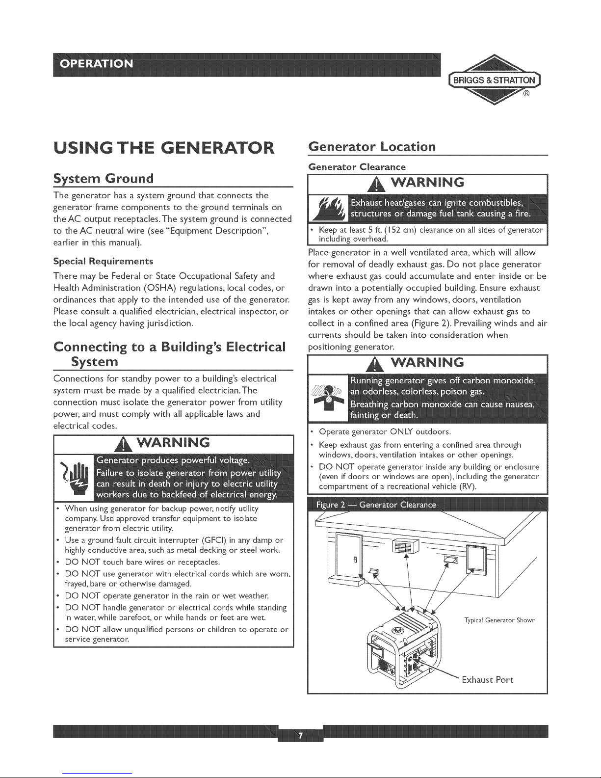
Generator Clearance
WANNmNG
Keep at least 5 ft. (152 cm) clearance on all sidesof generator
including overhead.
Place generator in a well ventilated area, which will allow
for removal of deadly exhaust gas. Do not place generator
where exhaust gas could accumulate and enter inside or be
drawn into a potentially occupied building. Ensure exhaust
gas is kept away from any windows, doors, ventilation
intakes or other openings that can allow exhaust gas to
collect in a confined area (Figure 2). Prevailing winds and air
currents should be taken into consideration when
positioning generator.
WANNmNG
Operate generator ONLY outdoors.
Keep exhaust gas from entering a confined area through
windows, doors, ventilation intakes or other openings.
DO NOT operate generator inside any building or enclosure
(even if doors or windows are open), including the generator
compartment of a recreational vehicle (RV).
service generator
Typical Generator Shown
Exhaust Port
1

OPERATING THE
Starting the Engine
Disconnect all electrical loads from the generator. Use the
following start instruction steps in numerical order:
I. btake sure unit is on a level surface.
iMPORTANT: Failure to start and operate unit on a level
surface will cause the unit not to start or shut down during
operation.
2. Turn fuel valve to "On" position (Figure 3).
.
Start the engine according to instructions given in the
engine operator's manual.
WARNmNG
When starting engine, pull cord slowly until resistance is felt
and then pull rapidly to avoid kickback.
NEVER start or stop engine with electrical devices plugged in
and turned on.
WARNmNG
DO NOT touch hot surfaces and avoid hot exhaust gases,
Allow equipment to coo[ before touching.
Keep at least 5 ft. ([ 52 cm) clearance on all sides of generator
including overhead.
Code of Federal Regulation (CFR) Title 36 Parks, Forests, and
Public Property require equipment powered by an internal
combustion engine to have a spar[< attester, maintained in
effective working order, complying to USDA Forest service
standard 5[O0-IC or later revision. In the State of California a
spark attester is required under section 4442 of the California
Public resources code. Other states may have similar laws.
Electrical Loads
Let engine stabilize and warm up for a few minutes after
starthg.
, Plug in and turn on the desired 120 and/or 240 Volt AC,
single phase, 60 Hz electrical loads.
, DO NOT connect 240Volt loads to the 120Volt duplex
receptacles.
, DO NOT connect 3-phase loads to the generator.
, DO NOT connect 50 Hz loads to the generator.
o DO NOT OVERLOAD THE GENERATOR. See
"Don't Overload Generator".
NOTE: If engine starts after 3 pulls but fails to run, or if
unit shuts down during operation, make sure unit is on a
level surface and check for proper oil level in crankcase.
This unit may be equipped with a low oil protection device.
See engine operator's manual.
See "Don't Overload Generator".
Start generator and let engine stabilize before connecting
electrical loads,
Connect electrical loads in OFF position, then turn ON for
operation.
Turn electrical loads OFF and disconnect from generator
before stopping generator.

$to$ the Engine
I. Turn OFF and unplug ALL electrical loads from
generator panel receptacles. NEVER start or stop engine
with electrical devices plugged in and turned ON.
2. Let engine run at no-load for several minutes to
stabilize internal temperatures of engine and generator.
3. Hove fuel valve to'°Off' position.
4. Turn engine off according to instructions given in the
engine operator's manual.
COLD WEATHER
OPERATION
Under certain weather conditions (temperatures below
40°F [4°C] combined with high humidity), your generator
may experience icing of the carburetor and/or the
crankcase breather system.To reduce this problem, you
need to perform the following:
I. Hake sure generator has clean, fresh fuel.
2. Open fuel valve (turn valve to open position).
3. Use SAE 5W-30 oil (synthetic preferred, see engine
operator's manual).
4. Check oil level daily or after every eight (8) hours of
operation.
S. Haintain generator following"Haintenance Schedule"
in engine operator's manual.
6. Shelter unit from elements.
Creating a Temporary Shelter
[. [n an emergency, use the original shipping carton.
2. Cut off top carton flaps and one long side of carton to
expose muffler side of unit. If required, tape up other
sides of carton to fit over generator as shown in
Figure 4.
NOTE: If required, remove wheel kit to fit carton over
generator as shown in Figure 4.
3. Cut appropriate slots to access receptacles of unit.
4. Face exposed end away from wind and elements.
5. Locate generator as described in the section
"Generator Location". Keep exhaust gas from entering
a confined area through windows, doors, ventilation
intakes or other openings.
WANNING
Operate generator ONLY outdoors.
Keep exhaust gas from entering a confined area through
windows, doors, ventilation intakes or other openings.
DO NOT operate generator inside any building or enclosure
(even if doors or windows are open), including the generator
compartment of a recreational vehicle (RV).

.
Start generator as described in the section "Starting
the Engine", then place carton over generator. Keep at
least 5 ft. (152 cm) clearance on all sides of generator
including overhead with shelter in place.
WARNmNG
DO NOT touch hot surfaces and avoid hot exhaust gases.
Allow equipment to cool before touching.
Keep at least 5 ft. (152 cm) clearance on all sides of generator
including overhead.
Remove shelter when temperatures are above 40°F [4°C].
7. Remove shelter when temperatures are above 40°F
[4oc].
8. Turn engine OFF and let cool two (2) minutes before
refueling.Wipe up any spilled fuel.
Creating a Permanent Shelter
I. Build a structure that will enclose three sides and the
top of the generator, making sure muffler side of
generator is exposed.
NOTE: Structure should hold enough heat created by the
generator to prevent icing problem.
2. DO NOT enclose generator any more than shown in
Figure 4.
NOTE: If a wheel kit is installed on the generator, enlarge
shelter accordingly.
3. Follow steps 3 through 8 as described previously in
"Creating a Temporary Shelter".
RECEPTACLES
A double pole rocker switch circuit breaker is provided to
protect all the receptacles and generator against electrical
overload.
NEVER attempt to power a device requiring more amperage
than generator or receptacle can supply.
DO NOT overload the generatom: See "Don't Overload
Generator _',
[ 20/240 Volt AC, 20 Amp Locking
Receptacle
Use a NEP1A LI4-20 plug with this receptacle. Connect a
4-wire cord set rated for 250Voks AC at 20 Amps (or
greater) (Figure 5).You can use the same 4-wire cord if you
4an to run a 120Vok load.
," iiii,
4-Wire Cord Set
(Neutral)
Y (Hot) | X (Hot)
NEMA L14-20 _ Ground(Green)
This receptacle powers 120i240VokAC, 60 Hz, single
phase loads requiring up to 2,000 watts of power at
16.6 Amps for 120Volts; 4,000 watts of power (4.0 kVV) at
16.6 Amps for 240Volts.The outlet is protected by a
double pole rocker switch circuit breaker.
IMPORTANT: This generator's locking receptacle and the
provided adapter cord set are not protected by a Ground
Fauk Circuit Interrupter (GFC[). If used on an OSHA
governed job site, appropriate GFCI protection must be
utilized.
[ 20Volt AC, [ 5 Amp, GFC[ Duplex
Receptacles
Each duplex receptacle (Figure 6) is protected against
overload by a push-to-reset circuit breaker.
NOTE: If the double pole circuit breaker [s tripped, the
duplex receptacles are disconnected.
Use each receptacle to operate 120VoltAC, single-phase,
60 Hz electrical loads requirhg up to 1,800 watts (1.8 kV_)
at 15 Amps of current. Use cord sets that are rated for
125 Volt AC loads at I5 Amps (or greater). Inspect cord
sets before each use.
 Loading...