

Briggs & Stratton 30244 User Manual
Model / Modelo
030244
Operator’s Manual
Manual del Operario
Questions? Help is just a moment away!
Preguntas? La ayuda es justa un momento lejos!
Call: Generator Helpline
Llame: Línea Directa del Generador
1-800-743-4115 M-F 8-5 CT
web: www.briggsandstratton.com
BRIGGS & STRATTON POWER PRODUCTS GROUP, LLC
JEFFERSON,WISCONSIN, U.S.A.
Manual No. 199825GS
Revision A (06/14/2006)
EXL8000
13500 STARTING WATTS
Before using this product, read this manual and follow all
Safety Rules and Operating Instructions.
WARNING
Antes de utilizar el producto, lea este manual y siga todas las
Reglas de Seguridad e Instrucciones de Uso.
ADVERTENCIA
2
SAFETY RULES
TABLE OF CONTENTS
Safety Rules. . . . . . . . . . . . . . . . . . . . . . . . . . . . . . . . . . . . 2-4
Know Your Generator. . . . . . . . . . . . . . . . . . . . . . . . . . . . . 5
Assembly. . . . . . . . . . . . . . . . . . . . . . . . . . . . . . . . . . . . . . 6-7
Operation . . . . . . . . . . . . . . . . . . . . . . . . . . . . . . . . . . . . 8-14
Specifications . . . . . . . . . . . . . . . . . . . . . . . . . . . . . . . . . . . 15
Maintenance . . . . . . . . . . . . . . . . . . . . . . . . . . . . . . . . . 16-21
Storage . . . . . . . . . . . . . . . . . . . . . . . . . . . . . . . . . . . . . . . . 22
Troubleshooting. . . . . . . . . . . . . . . . . . . . . . . . . . . . . . . . . 23
Notes . . . . . . . . . . . . . . . . . . . . . . . . . . . . . . . . . . . . . . . . . 24
Emissions Control Warranties. . . . . . . . . . . . . . . . . . . 25-27
Warranties . . . . . . . . . . . . . . . . . . . . . . . . . . . . . . . . . . 28-29
Español . . . . . . . . . . . . . . . . . . . . . . . . . . . . . . . . . . . . . 30-56
EQUIPMENT
DESCRIPTION
Read this manual carefully and become
familiar with your generator. Know its
applications, its limitations and any hazards
involved.
The generators are an engine–driven, revolving field,
alternating current (AC) generator. It was designed to
supply electrical power for operating compatible electrical
lighting, appliances, tools and motor loads.The generator’s
revolving field is driven at about 3,600 rpm by a singlecylinder engine.
CAUTION! DO NOT exceed the generator’s
wattage/amperage capacity. See “Don’t Overload
Generator”.
Every effort has been made to ensure that information in
this manual is accurate and current. However, we reserve
the right to change, alter or otherwise improve the product
and this document at any time without prior notice.
The Emission Control System for this generator is
warranted for standards set by the Environmental
Protection Agency and the California Air Resources Board.
SAFETY RULES
This is the safety alert symbol. It is used to
alert you to potential personal injury hazards.
Obey all safety messages that follow this
symbol to avoid possible injury or death.
The safety alert symbol ( ) is used with a signal word
(DANGER, CAUTION,WARNING), a pictorial and/or a
safety message to alert you to hazards. DANGER indicates
a hazard which, if not avoided, will result in death or serious
injury. WARNING indicates a hazard which, if not avoided,
could result in death or serious injury. CAUTION
indicates a hazard which, if not avoided, might result in
minor or moderate injury. CAUTION, when used
without the alert symbol, indicates a situation that could
result in equipment damage. Follow safety messages to
avoid or reduce the risk of injury or death.
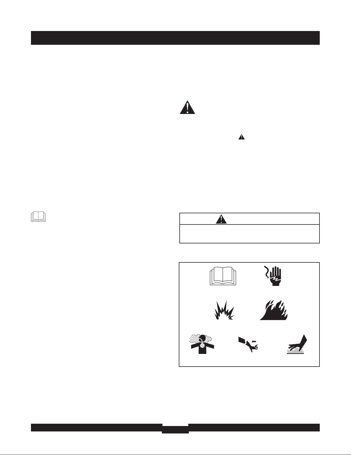
Hazard Symbols and Meanings
The engine exhaust from this product contains
chemicals known to the State of California to cause
cancer, birth defects, or other reproductive harm.
WARNING
Copyright © 2006 Briggs & Stratton Power Products
Group, LLC. All rights reserved. No part of this material
may be reproduced or transmitted in any form by any
means without the express written permission of Briggs &
Stratton Power Products Group, LLC.
SAVE THESE INSTRUCTIONS
Fire
Explosion
Toxic Fumes
Hot Surface
Electrical Shock
Kickback
Operator’s Manual
3
SAFETY RULES
• This generator does not meet U. S. Coast Guard Regulation
33CFR-183 and should not be used on marine applications.
• Failure to use the appropriate U. S. Coast Guard approved
generator could result in death or serious injury and/or
property damage.
WARNING
• When using generator for backup power, notify utility
company. Use approved transfer equipment to isolate
generator from electric utility.
• Use a ground fault circuit interrupter (GFCI) in any damp or
highly conductive area, such as metal decking or steel work.
• DO NOT touch bare wires or receptacles.
• DO NOT use generator with electrical cords which are worn,
frayed, bare or otherwise damaged.
• DO NOT operate generator in the rain or wet weather.
• DO NOT handle generator or electrical cords while standing
in water, while barefoot, or while hands or feet are wet.
• DO NOT allow unqualified persons or children to operate or
service generator.
Generator produces powerful voltage.
Failure to isolate generator from power utility
can result in death or injury to electric utility
workers due to backfeed of electrical energy.
WARNING
• Operate generator ONLY outdoors.
• Keep exhaust gas from entering a confined area through
windows, doors, ventilation intakes or other openings.
• DO NOT operate generator inside any building or enclosure
(even if doors or windows are open),including the generator
compartment of a recreational vehicle (RV).
Running generator gives off carbon monoxide,
an odorless, colorless, poison gas.
Breathing carbon monoxide can cause nausea,
fainting or death.
WARNING
WHEN ADDING OR DRAINING FUEL
• Turn generator OFF and let it cool at least 2 minutes before
removing fuel cap.Loosen cap slowly to relieve pressure in
tank.
• Fill or drain fuel tank outdoors.
• DO NOT overfill tank.Allow space for fuel expansion.
• Wait for spilled fuel to evaporate before starting engine.
• Keep fuel away from sparks, open flames, pilot lights, heat, and
other ignition sources.
• DO NOT light a cigarette or smoke.
WHEN STARTING EQUIPMENT
• Ensure spark plug, muffler, fuel cap and air cleaner are in place.
• DO NOT crank engine with spark plug removed.
WHEN OPERATING EQUIPMENT
• DO NOT tip engine or equipment at angle which causes fuel
to spill.
• This generator is not for use in mobile equipment or marine
applications.
WHEN TRANSPORTING OR REPAIRING
EQUIPMENT
• Transport/repair with fuel tank EMPTY or with fuel shutoff
valve OFF.
• Disconnect spark plug wire.
WHEN STORING FUEL OR EQUIPMENT WITH FUEL
IN TANK
• Store away from furnaces, stoves, water heaters, clothes
dryers or other appliances that have pilot light or other
ignition source because they can ignite fuel vapors.
Fuel and its vapors are extremely flammable and
explosive.
Fire or explosion can cause severe burns or
death.
WARNING
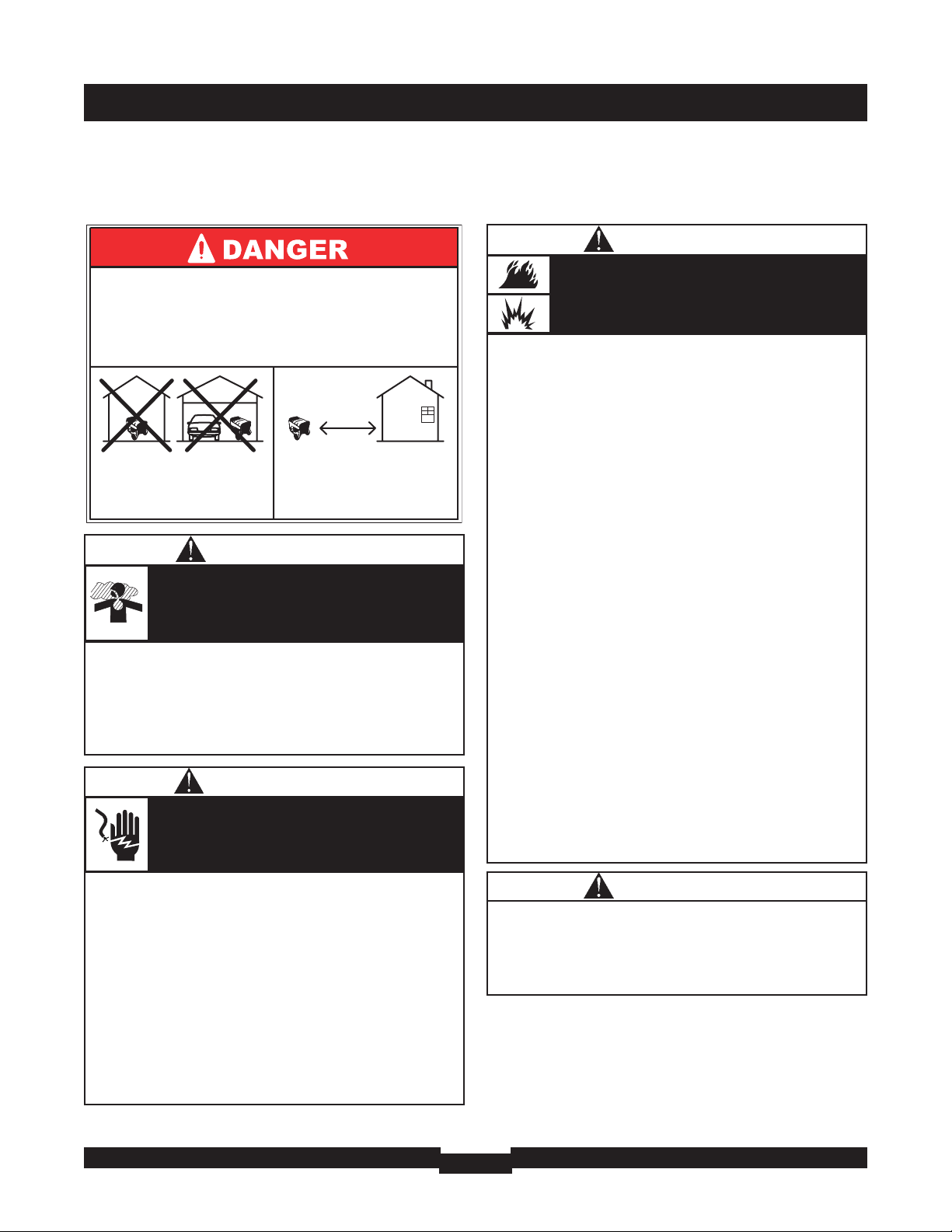
Using a generator indoors WILL KILL YOU
IN MINUTES.
Exhaust contains carbon monoxide, a
poison gas you cannot see or smell.
NEVER use in the home
or in partly enclosed
areas such as garages.
ONLY use outdoors and
far from open windows,
doors, and vents.

SAFETY RULES
4
• DO NOT tamper with governed speed. Generator supplies
correct rated frequency and voltage when running at governed
speed.
• DO NOT modify generator in any way.
Excessively high operating speeds increase risk of injury
and damage to generator.
Excessively low speeds impose a heavy load.
CAUTION
• See “Don’t Overload Generator”.
• Start generator and let engine stabilize before connecting
electrical loads.
• Connect electrical loads in OFF position, then turn ON for
operation.
• Turn electrical loads OFF and disconnect from generator
before stopping generator.
Exceeding generators wattage/amperage capacity can
damage generator and/or electrical devices connected
to it.
CAUTION
• Use generator only for intended uses.
• If you have questions about intended use, ask dealer or call
1-800-743-4115.
• Operate generator only on level surfaces.
• DO NOT expose generator to excessive moisture, dust, dirt,
or corrosive vapors.
• DO NOT insert any objects through cooling slots.
• If connected devices overheat, turn them off and disconnect
them from generator.
• Shut off generator if:
-electrical output is lost;
-equipment sparks, smokes, or emits flames;
-unit vibrates excessively.
Improper treatment of generator can damage it and
shorten its life.
CAUTION
WHEN ADJUSTING OR MAKING REPAIRS TO YOUR
GENERATOR
• Disconnect the spark plug wire from the spark plug and place
the wire where it cannot contact spark plug.
WHEN TESTING FOR ENGINE SPARK
• Use approved spark plug tester.
• DO NOT check for spark with spark plug removed.
Unintentional sparking can result in fire or
electric shock.
WARNING
• DO NOT touch hot surfaces and avoid hot exhaust gases.
• Allow equipment to cool before touching.
• Keep at least 5 ft. (152 cm) clearance on all sides of generator
including overhead.
• Code of Federal Regulation (CFR) Title 36 Parks, Forests,and
Public Property require equipment powered by an internal
combustion engine to have a spark arrester, maintained in
effective working order, complying to USDA Forest service
standard 5100-1C or later revision. In the State of California a
spark arrester is required under section 4442 of the California
Public resources code. Other states may have similar laws.
Running engines produce heat.Temperature of
muffler and nearby areas can reach or exceed
150°F (65°C).
Severe burns can occur on contact.
Exhaust heat/gases can ignite combustibles,
structures or damage fuel tank causing a fire.
WARNING
• When starting engine, pull cord slowly until resistance is felt
and then pull rapidly to avoid kickback.
• NEVER start or stop engine with electrical devices plugged in
and turned on.
Rapid retraction of starter cord (kickback) will
pull hand and arm toward engine faster than
you can let go.
Broken bones, fractures, bruises or sprains could
result.
WARNING

KNOW YOUR GENERATOR
5
KNOW YOUR GENERATOR
Read this operator’s manual and safety rules before operating your generator.
Compare the illustrations with your generator to familiarize yourself with the locations of various controls and
adjustments. Save this manual for future reference.
Choke Lever
120 Volt AC, 15 Amp
GFCI Duplex Receptacles
Run/Stop Switch
Spark Arrester
Muffler
Start Switch
Grounding
Fastener
Air Cleaner
Fuel Tank
Oil Fill Cap
Data Tag
Hour Meter
Battery Float Charger Jack
Circuit
Breakers (AC)
120/240 Volt AC, 30 Amp
Locking Receptacle
Double Pole
Circuit Breaker
120 Volt AC, 15 Amp GFCI Duplex Receptacles —
May be used to supply electrical power for the operation of
120 Volt AC, 15 Amp, single phase, 60 Hz electrical lighting,
appliance, tool and motor loads.
120/240 Volt AC, 30 Amp Locking Receptacle — May
be used to supply electrical power for the operation of
120 and/or 240 Volt AC, 30 Amp, single phase, 60 Hz
electrical lighting, appliance, tool and motor loads.
Air Cleaner — Protects engine by filtering dust and
debris out of intake air.
Battery Float Charger Jack — Use battery float
charger to keep the starting battery charged and ready for
use.
Choke Lever — Used when starting a cold engine.
Circuit Breakers (AC) — Push to reset circuit breakers
are provided to protect the generator against electrical
overload.
Data Tag – Provides model, revision and serial number of
generator. Please have these readily available if calling for
assistance.
Double Pole Circuit Breaker (AC) — A double pole
circuit breaker is provided to protect the 30A receptacle
and generator against electrical overload.
Fuel Tank — Capacity of seven (7) U.S. gallons.
Fuel Valve — Used to turn fuel supply on and off to engine.
Grounding Fastener — Consult your local agency having
jurisdiction for grounding requirements in your area.
Hour Meter — Displays and records how many hours
your generator has run (up to 9,999.9).
Oil Fill Cap — Add oil to engine here.
Recoil Starter — Used to start the engine manually.
Run/Stop Switch — Set this switch to "Run" before
starting engine. Set switch to "Stop" to switch off engine.
Spark Arrester Muffler — Exhaust muffler lowers engine
noise and is equipped with a spark arrester screen.
Start Switch — Push and hold in “Start” position for a
maximum of 15 seconds during each start attempt, until
engine starts.
Recoil Starter
Fuel Valve

ASSEMBLY
6
ASSEMBLY
Your generator requires some assembly and is ready for
use after it has been properly serviced with the
recommended oil and fuel.
If you have any problems with the assembly of your
generator, please call the generator helpline at
1-800-743-4115. If calling for assistance, please have the
model, revision,and serial number from the data tag available.
See “Know Your Generator” for data tag location.
Unpacking the Generator
1. Set the carton on a rigid flat surface.
2. Open carton completely by cutting each corner from
top to bottom.
3. Cut ties holding accessory kit and extension cord to
generator and remove everything from carton.
ELECTRIC START
Your unit is equipped with electric start capability but can
be started manually. If you choose not to use the electric
start feature, you do not need to install the negative
battery cable.
Check Battery / Attach Negative
Battery Wire
The sealed battery on the generator is fully charged and
pre–installed except for the negative (black) battery cable.
You will need the following tools to install the negative
battery cable:
• Socket wrench with a 8 mm socket
• Diagonal cutters
To install:
1. Cut off tie wrap securing loose end of negative (black)
cable.
2. Using a 8 mm socket wrench, remove screw, lock
washer and flat washer on negative battery terminal.
3. Slide lock washer, flat washer and negative battery
cable over screw (Figure 1).
4. Reattach screw to negative battery terminal and
tighten.
5. Verify that connections to battery and generator are
tight and secure.
Figure 1 — Negative Battery Connection
Negative
Battery Cable
Screw
Flat Washer
Lock Washer
Positive
Battery Cable
7
ASSEMBLY
BEFORE STARTING THE
ENGINE
Add Engine Oil
CAUTION! Any attempt to crank or start the engine
before it has been properly serviced with the
recommended oil may result in an engine failure.
1. Place generator on a flat, level surface.
2. Clean area around oil fill and remove yellow oil fill cap.
3. Using oil funnel (optional), slowly pour contents of
both provided oil bottles into oil fill opening to the
point of overflowing.
4. Replace oil fill cap and fully tighten.
NOTE: See the section “Oil” on page 17 to review oil
recommendations.
Add Fuel
NOTE:This gasoline engine is certified to operate on
gasoline. Exhaust Emission Control System: EM (Engine
Modifications).
1. Use clean, fresh, regular UNLEADED fuel with a
minimum of 87 octane. DO NOT use fuel which
contains Methanol. DO NOT mix oil with fuel.
2. Clean area around fuel fill cap, remove cap.
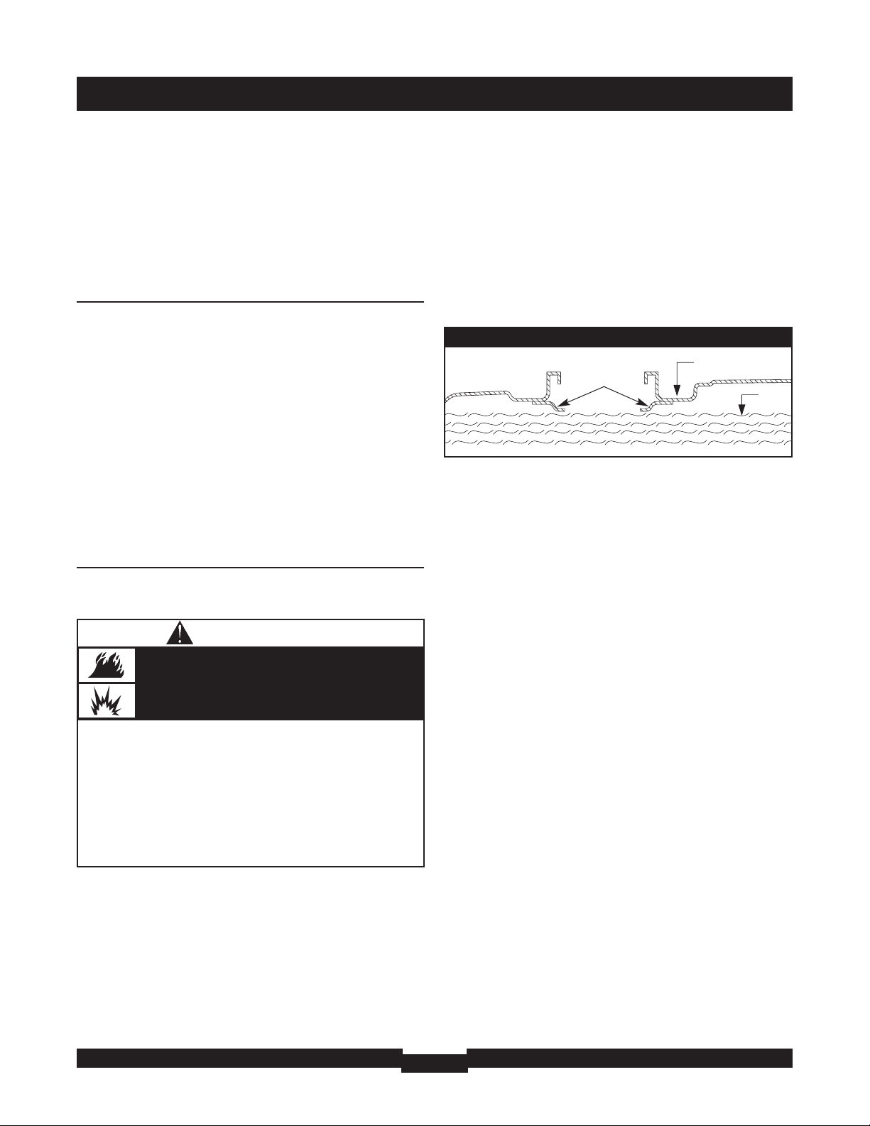
3. Slowly add regular unleaded fuel to fuel tank. Be careful
not to fill above the baffle.This allows adequate space
for fuel expansion (Figure 2).
4. Install fuel cap and let any spilled fuel evaporate before
starting engine.
CAUTION! Alcohol-blended fuels (called gasohol,
ethanol or methanol) can attract moisture, which leads to
separation and formation of acids during storage.Acidic gas
can damage the fuel system of an engine while in storage.
To avoid engine problems, the fuel system should be
treated with a fuel preserver or emptied before storage of
30 days or longer. If adding a fuel preserver, fill the fuel tank
with fresh fuel. If only partially filled, air in the tank will
promote fuel deterioration during storage. If fuel preserver
is not used, drain the fuel tank, start the engine and let it
run until the fuel lines and carburetor are empty. Use fresh
fuel next season. See “Storage” on page 22 for additional
information.
NEVER use engine or carburetor cleaner products in the
fuel tank as permanent damage may occur.
WHEN ADDING FUEL
• Turn generator OFF and let it cool at least 2 minutes before
removing fuel cap.Loosen cap slowly to relieve pressure in tank.
• Fill fuel tank outdoors.
• DO NOT overfill tank.Allow space for fuel expansion.
• Wait for spilled fuel to evaporate before starting engine.
• Keep fuel away from sparks, open flames, pilot lights, heat, and
other ignition sources.
• DO NOT light a cigarette or smoke.
Fuel and its vapors are extremely flammable and
explosive.
Fire or explosion can cause severe burns or
death.
WARNING
FUEL
TANK
Figure 2 — Typical Fuel Expansion Space
Baffle

OPERATION
8
USING THE GENERATOR
System Ground
The generator has a system ground that connects the
generator frame components to the ground terminals on
the AC output receptacles.The system ground is connected
to the AC neutral wire (the neutral is bonded to the
generator frame).
Special Requirements
There may be Federal or State Occupational Safety and
Health Administration (OSHA) regulations, local codes, or
ordinances that apply to the intended use of the generator.
Please consult a qualified electrician, electrical inspector, or
the local agency having jurisdiction.
Connecting to a Building’s Electrical
System
Connections for standby power to a building’s electrical
system must be made by a qualified electrician.The
connection must isolate the generator power from utility
power, and must comply with all applicable laws and
electrical codes.
Generator Location
Generator Clearance
Place generator in a well ventilated area, which will allow
for removal of deadly exhaust gas. DO NOT place
generator where exhaust gas could accumulate and enter
inside or be drawn into a potentially occupied building.
Ensure exhaust gas is kept away from any windows,doors,
ventilation intakes or other openings that can allow exhaust
gas to collect in a confined area (Figure 3). Prevailing winds
and air currents should be taken into consideration when
positioning generator.
• When using generator for backup power, notify utility
company. Use approved transfer equipment to isolate
generator from electric utility.
• Use a ground fault circuit interrupter (GFCI) in any damp or
highly conductive area, such as metal decking or steel work.
• DO NOT touch bare wires or receptacles.
• DO NOT use generator with electrical cords which are worn,
frayed, bare or otherwise damaged.
• DO NOT operate generator in the rain or wet weather.
• DO NOT handle generator or electrical cords while standing
in water, while barefoot, or while hands or feet are wet.
• DO NOT allow unqualified persons or children to operate or
service generator.
Generator produces powerful voltage.
Failure to isolate generator from power utility
can result in death or injury to electric utility
workers due to backfeed of electrical energy.
WARNING
• Keep at least 5 ft. (152 cm) clearance on all sides of generator
including overhead.
Exhaust heat/gases can ignite combustibles,
structures or damage fuel tank causing a fire.
WARNING
Figure 3 — Generator Clearance
Exhaust Port
Typical Generator Shown
Using a generator indoors WILL KILL YOU
IN MINUTES.
Exhaust contains carbon monoxide, a
poison gas you cannot see or smell.
NEVER use in the home
or in partly enclosed
areas such as garages.
ONLY use outdoors and
far from open windows,
doors, and vents.

9
OPERATION
OPERATING THE
GENERATOR
Starting the Engine
IMPORTANT: Always unplug the battery float charger
before starting the generator.
Disconnect all electrical loads from the generator. Use the
following start instructions:
1. Make sure unit is on a level surface.
IMPORTANT: Failure to start and operate unit on a level
surface will cause the unit not to start or shut down during
operation.
2. Turn fuel valve to “On” position (Figure 4).
3. Set run/stop switch to “Run” position (Figure 5).
4. Place choke lever in “Full” choke position (Figure 6).
5A. For electric starting, push and hold the start switch
in start position (Figure 7) until generator starts.To
prolong the life of starter components, DO NOT hold
start switch in start position for more than
15 seconds, and pause for at least 1 minute between
starting atempts.
• If engine starts, proceed to step 7.
• If engine fails to start, proceed to step 6.
NOTE: If battery is discharged, use manual starting
instructions.
5B. For manual starting, grasp recoil handle and pull
slowly until slight resistance is felt.Then pull rapidly
one time only to start engine.
• If engine starts, proceed to step 7.
• If engine fails to start, proceed to step 6.
6. Move choke lever to “Half” choke position, and pull
recoil handle twice.
• If engine fails to start, repeat steps 5 thru 7.
7. Slowly move choke lever to “Run” position. If engine
falters, move choke lever to “Half” choke position
until engine runs smoothly, and then to “Run” position.
NOTE: If engine starts after 3 pulls, but fails to run for
more than 10 seconds, check for proper oil level in
crankcase.This unit is equipped with a Low Oil Pressure
Shutdown System. See “Low Oil Pressure Shutdown
System”.
• When starting engine, pull cord slowly until resistance is felt
and then pull rapidly to avoid kickback.
• NEVER start or stop engine with electrical devices plugged in
and turned on.
Rapid retraction of starter cord (kickback) will
pull hand and arm toward engine faster than
you can let go.
Broken bones, fractures, bruises or sprains could
result.
WARNING
Figure 4 — Fuel Shut-off Valve
Figure 7 — Start Switch
Figure 5 — Run/Stop Switch
Figure 6 — Choke Lever
OPERATION
10
Connecting Electrical Loads
• Let engine stabilize and warm up for a few minutes after
starting.
• Plug in and turn on the desired 120 and/or 240 Volt AC,
single phase, 60 Hz electrical loads.
• DO NOT connect 240 Volt loads to the 120 Volt duplex
receptacles.
• DO NOT connect 3–phase loads to the generator.
• DO NOT connect 50 Hz loads to the generator.
• DO NOT OVERLOAD THE GENERATOR. See
“Don’t Overload Generator”.
Stopping the Engine
1. Turn OFF and unplug all electrical loads from generator
panel receptacles. NEVER start or stop engine with
electrical devices plugged in and turned ON.
2. Let engine run at no-load for several minutes to
stabilize internal temperatures of engine and generator.
3. Move Run/Stop switch to “Stop” position.
4. Move fuel valve to “Off” position.
Low Oil Pressure Shutdown System
The engine is equipped with a low oil pressure sensor that
shuts down the engine automatically when the oil pressure
drops below 8 psi. If the engine shuts down by itself and
the fuel tank has enough gasoline, check engine oil level.
Initial Start–up
A delay built into the low oil shutdown system allows oil
pressure to build during starting.The delay allows the
engine to run for about 10 seconds before sensing oil
pressure.
Sensing Low Pressure
If the system senses low oil pressure during operation, the
engine shuts down.As the system shuts down, the low oil
light comes ON. However, once the engine has stopped
rotating, this light will go OFF.
Restarting
If you try to restart the engine within 10 seconds after it
shuts down, the engine may NOT start.The system needs
5 to 10 seconds to reset.
If you do restart the engine after such a shutdown and have
not corrected the low oil pressure, the engine runs for
about 10 seconds as described above and then stops.
RECEPTACLES
A double pole rocker switch circuit breaker is provided to
protect the locking receptacle. If this circuit breaker is
tripped, all panel receptacles are disconnected.
• See “Don’t Overload Generator”.
• Start generator and let engine stabilize before connecting
electrical loads.
• Connect electrical loads in OFF position, then turn ON for
operation.
• Turn electrical loads OFF and disconnect from generator
before stopping generator.
Exceeding generator’s wattage/amperage capacity can
damage generator and/or electrical devices connected to it.
CAUTION
• DO NOT touch hot surfaces and avoid hot exhaust gases.
• Allow equipment to cool before touching.
• Keep at least 5 ft. (152 cm) clearance on all sides of generator
including overhead.
• Code of Federal Regulation (CFR) Title 36 Parks, Forests,and
Public Property require equipment powered by an internal
combustion engine to have a spark arrester, maintained in
effective working order, complying to USDA Forest service
standard 5100-1C or later revision. In the State of California a
spark arrester is required under section 4442 of the California
Public resources code. Other states may have similar laws.
Running engines produce heat.Temperature of
muffler and nearby areas can reach or exceed
150°F (65°C).
Severe burns can occur on contact.
Exhaust heat/gases can ignite combustibles,
structures or damage fuel tank causing a fire.
WARNING
• NEVER attempt to power a device requiring more amperage
than generator or receptacle can supply.
• DO NOT overload the generator.See “Don’t Overload
Generator”.
Receptacles may be marked with rating value greater
than generator output capacity.
CAUTION

OPERATION
11
120/240 Volt AC, 30 Amp, Locking
Receptacle
Use a NEMA L14–30 plug with this receptacle. Connect a
4–wire cord set rated for 250 Volt AC loads at 30 Amps (or
greater) (Figure 8).You can use the same 4–wire cord if you
plan to run a 120 Volt load.
This receptacle powers 120/240 Volt AC, 60 Hz, single
phase loads requiring up to 7,200 watts of power (7.2 kW)
at 30 Amps for 240 Volts or two independent 120 Volt
loads at 30 Amps each.The outlet is protected by a double
pole rocker switch circuit breaker.
IMPORTANT: This generator’s locking receptacle and the
provided adapter cord set are not protected by a Ground
Fault Circuit Interrupter (GFCI). If used on an OSHA
governed job site, appropriate GFCI protection must be
utilized.
120 Volt AC, 15 Amp, GFCI Duplex
Receptacles
Each duplex receptacle (Figure 9) is protected against
overload by a push–to–reset circuit breaker.
NOTE: If the double pole circuit breaker is tripped, the
duplex receptacles are disconnected.
Use each receptacle to operate 120 Volt AC, single–phase,
60 Hz electrical loads requiring up to 1,800 watts (1.8 kW)
at 15 Amps of current. Use grounded cord sets that are
rated for 125 Volt AC loads at 15 Amps (or greater).
Inspect cord sets before each use.
Ground Fault Protection
The duplex receptacles are equipped with Ground Fault
Circuit Interrupter (GFCI) protection.This device meets
applicable federal, state and local codes.The generator’s
locking receptacle is not protected by a GFCI.
The GFCI protects against electrical shock that may be
caused if your body becomes a path which electricity
travels to reach the ground.This could happen if you touch
a “Live” appliance or wire, or are touching plumbing or
other materials that connect to the ground.
When protected by a GFCI, one may still feel a shock, but
the GFCI should cut current off quickly enough so that a
person in normal health should not suffer any serious
electrical injury.
Figure 8 — 120/240 Volt AC, 30 Amp Receptacle
4-Wire Cord Set
240V
120V
120V
W (Neutral)
X (Hot)
Y (Hot)
NEMA L14-30
Ground (Green)
Figure 9 — 120 Volt, 15 Amp GFCI Duplex Receptacle
• The GFCI will not protect you against the following situations:
-Line-to-line shocks;
-Current overloads or line-to-line short circuits.
• The circuit breakers at the control panel provide overcurrent
protection.
Generator produces powerful voltage.
WARNING
OPERATION
12
Testing the GFCI
Test your GFCI outlet prior to each use, as follows:
• Push the black “Test” button.The red “Reset” button
should pop out, which should allow no power to reach
the outlet. Use a test lamp in each outlet to test this.
• If the GFCI tests good, restore power by pressing the
“Reset” button firmly until it is fully in place and locks in that
position. If the GFCI outlet does not reset properly, do
not use the outlet. Call or take your generator to a
local service center.
• If the GFCI trips by itself at any time, reset and test the
outlet. If the reset button does not pop out when
the test button is pressed, do not use the outlet.
Call or take your generator to a local service center.
GENERATOR ADAPTER
CORD SET
The generator is equipped with a 25’ generator adapter
cord set designed for a 240 Volt, 30 Amp grounded neutral
circuit (Figure 10).
The maximum load on each outlet is 15 Amps.The
maximum total load on both yellow wire outlets or black
wire outlets is 30 Amps. Each outlet is protected by a
15 Amp fuse.
IMPORTANT: This generator’s locking receptacle and the
provided adapter cord set are not protected by a Ground Fault
Circuit Interrupter (GFCI). If used on an OSHA governed job
site, appropriate GFCI protection must be utilized.
NOTE: Follow all safety precautions when connecting any
extension cord or device to the generator.
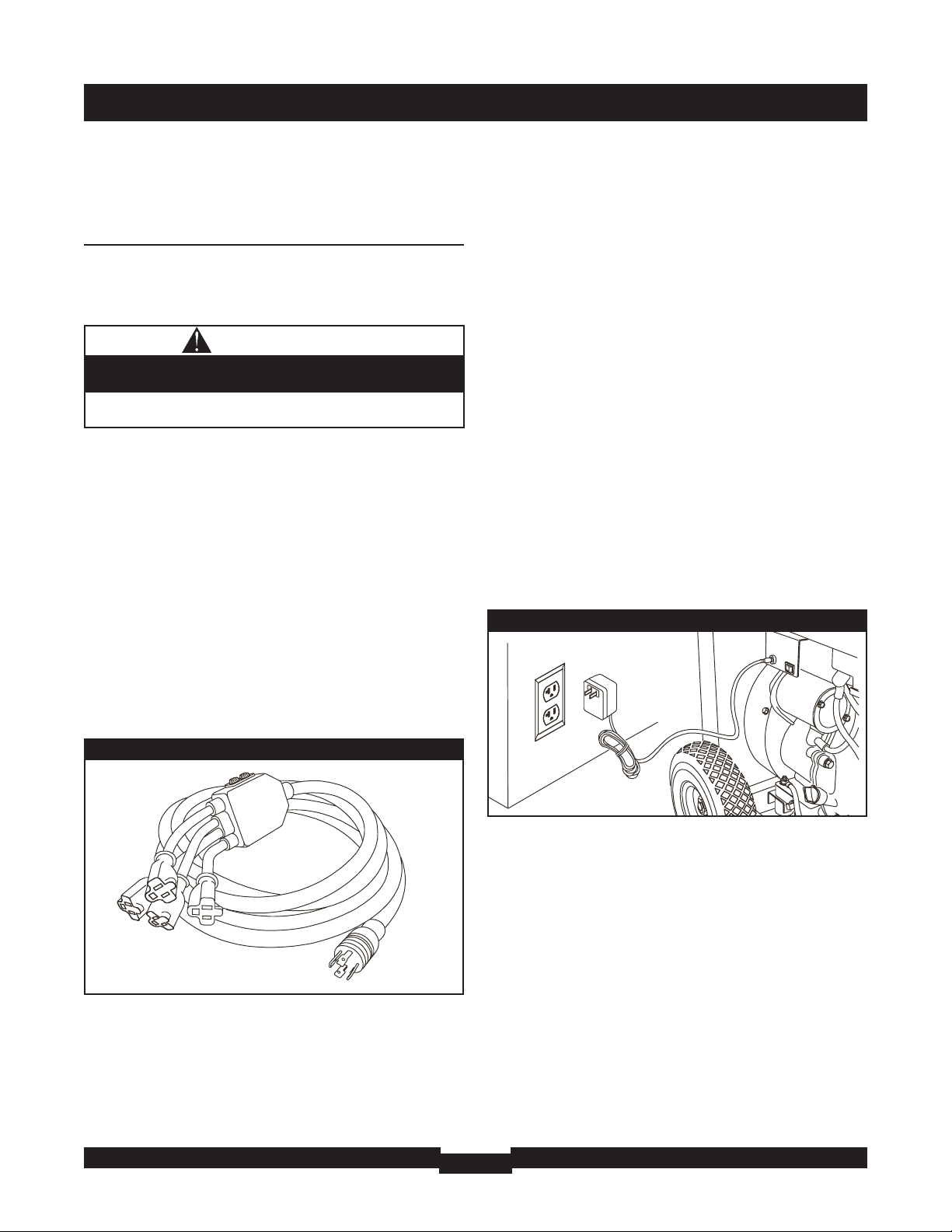
HOW TO USE THE
BATTERY CHARGER
Use battery float charger to keep the starting battery
charged and ready for use. Battery charging should be done
in a dry location, such as inside a garage.
1. Plug charger into unit’s “Battery Float Charger” jack,
which is located next to start switch (Figure 11). Plug
battery charger into a 120 Volt AC wall receptacle.
2. Unplug charger from unit and wall outlet when
generator is being started and while it is in operation.
3. Keep this charger plugged in and connected when
generator is not in use to prolong battery life.The
charger has a built in float equalizer and will not
overcharge battery, even when plugged in for an
extended period of time.
IMPORTANT: See “Battery Maintenance” on page 17 for
additional information.
Figure 10 — Generator Adapter Cord Set
Figure 11 — Battery Charger Jack
• DO NOT use any outlets on the circuit.
• Call or take your generator to a local service center.
The “Reset” button does not pop out or the test lamp
remains lit when the “Reset” button is popped out.
CAUTION

13
OPERATION
COLD WEATHER
OPERATION
Under certain weather conditions (temperatures below
40°F [4°C] combined with high humidity), your generator
may experience icing of the carburetor and/or the
crankcase breather system.To reduce this problem, you
need to perform the following:
1. Make sure generator has clean, fresh fuel.
2. Open fuel valve (turn valve to open position).
3. Use SAE 5W-30 oil.
4. Check oil level daily or after every eight (8) hours of
operation.
5. Maintain generator following “Maintenance Schedule”
on page 16.
6. Shelter unit from elements.
Creating a Temporary Cold Weather
Shelter
1. In an emergency, use the original shipping carton.
2. Cut off top carton flaps and one long side of carton to
expose muffler side of unit. If required, tape up other
sides of carton to fit over generator as shown in
Figure 12.
NOTE: If required, remove wheel kit to fit carton over
generator as shown in Figure 12.
3. Cut appropriate slots to access receptacles of unit.
4. Face exposed end away from wind and elements.
5. Locate generator as described in the section
“Generator Location”. Keep exhaust gas from entering
a confined area through windows, doors, ventilation
intakes or other openings.
6. Start generator as described in the section “Starting
the Engine”, then place carton over generator. Keep at
least 5 ft. (152 cm) clearance on all sides of generator
including overhead with shelter in place.
7. Remove shelter when temperatures are above 40°F
[4°C].
8. Turn engine OFF and let cool two (2) minutes before
refueling. Let any spilled fuel evaporate before starting
engine.
Creating a Permanent Cold Weather
Shelter
1. Build a structure that will enclose three sides and the
top of the generator, making sure muffler side of
generator is exposed.
NOTE: Structure should hold enough heat created by the
generator to prevent icing problem.
2. DO NOT enclose generator any more than shown in
Figure 12.
NOTE: If a wheel kit is installed on the generator, enlarge
shelter accordingly.
3. Follow steps 3 through 8 as described previously in
“Creating a Temporary Cold Weather Shelter”.
Figure 12 — Cold Weather Shelter
Wind
• Operate generator ONLY outdoors.
• Keep exhaust gas from entering a confined area through
windows, doors, ventilation intakes or other openings.
• DO NOT operate generator inside any building or enclosure
(even if doors or windows are open),including the generator
compartment of a recreational vehicle (RV).
Running generator gives off carbon monoxide,
an odorless, colorless, poison gas.
Breathing carbon monoxide can cause nausea,
fainting or death.
WARNING
Typical Generator
Shown
• DO NOT touch hot surfaces and avoid hot exhaust gases.
• Allow equipment to cool before touching.
• Keep at least 5 ft. (152 cm) clearance on all sides of generator
including overhead.
• Remove shelter when temperatures are above 40°F [4°C].
Running engines produce heat.Temperature of
muffler and nearby areas can reach or exceed
150°F (65°C).
Severe burns can occur on contact.
Exhaust heat/gases can ignite combustibles,
structures or damage fuel tank causing a fire.
WARNING

OPERATION
14
DON'T OVERLOAD
GENERATOR
Capacity
You must make sure your generator can supply enough
rated (running) and surge (starting) watts for the items you
will power at the same time. Follow these simple steps:
1. Select the items you will power at the same time.
2. Total the rated (running) watts of these items.This is
the amount of power your generator must produce to
keep your items running. See Figure 13.
3. Estimate how many surge (starting) watts you will
need. Surge wattage is the short burst of power
needed to start electric motor-driven tools or
appliances such as a circular saw or refrigerator.
Because not all motors start at the same time, total
surge watts can be estimated by adding only the
item(s) with the highest additional surge watts to the
total rated watts from step 2.
Example:
Total Rated (Running) Watts = 3075
Highest Additional Surge Watts = 1800
Total Generator Output Required = 4875
Power Management
To prolong the life of your generator and attached devices,
it is important to take care when adding electrical loads to
your generator.There should be nothing connected to the
generator outlets before starting it's engine.The correct
and safe way to manage generator power is to sequentially
add loads as follows:
1. With nothing connected to the generator, start the
engine as described in this manual.
2. Plug in and turn on the first load, preferably the largest
load you have.
3. Permit the generator output to stabilize (engine runs
smoothly and attached device operates properly.
4. Plug in and turn on the next load.
5. Again, permit the generator to stabilize.
6. Repeat steps 4 and 5 for each additional load.
NEVER add more loads than the generator capacity.Take
special care to consider surge loads in generator capacity,
as described above.
*Wattages listed are approximate only. Check tool or
appliance for actual wattage.
Tool or Appliance
Rated (Running)
Watts
Additional Surge
(Starting) Watts
Window Air
Conditioner
1200 1800
Refrigerator 800 1600
Deep Freezer 500 500
Television 500 Light (75 Watts) 75 -
3075 Total
Running Watts
1800 Highest
Surge Watts
Tool or Appliance
Rated*
(Running)
Watts
Additional
Surge
(Starting)
Watts
Essentials
Light Bulb - 75 watt
75
-
Deep Freezer
500
500
Sump Pump
800
1200
Refrigerator/Freezer - 18 Cu. Ft.
800
1600
Water Well Pump - 1/3 HP
1000
2000
Heating/Cooling
Window AC - 10,000 BTU
1200
1800
Window Fan
300
600
Furnace Fan Blower - 1/2 HP
800
1300
Kitchen
Microwave Oven - 1000 Watt
1000
-
Coffee Maker
1500
-
Electric Stove - Single Element
1500
-
Hot Plate
2500
-
Family Room
DVD/CD Player
100
-
VCR
100
-
Stereo Receiver
450
-
Color Television - 27”
500
-
Personal Computer w/17” monitor
800
-
Other
Security System
180
-
AM/FM Clock Radio
300
-
Garage Door Opener - 1/2 HP
480
520
Electric Water Heater - 40 Gallon
4000
-
DIY/Job Site
Quartz Halogen Work Light
1000
-
Airless Sprayer - 1/3 HP
600
1200
Reciprocating Saw
960
960
Electric Drill - 1/2 HP
1000
1000
Circular Saw - 7 1/4”
1500
1500
Miter Saw - 10”
1800
1800
Table Planer - 6”
1800
1800
Table Saw/Radial Arm Saw - 10”
2000
2000
Air Compressor - 1-1/2 HP
2500
2500
Figure 13 - Wattage Reference Chart

SPECIFICATIONS
15
ENGINE TECHNICAL
INFORMATION
This is a single cylinder, overhead valve(OHV), air cooled
engine. It is a low emissions engine.
In the State of California, this type of engine is certified by
the California Air Resources Board to meet emissions
standards for 1000 hours. Such certification does not grant
the purchaser, owner or operator of this engine any
additional warranties with respect to the performance or
operational life of this engine.The engine is warranted
solely according to the product and emissions warranties
stated elsewhere in this manual.
Emissions Compliance Period
This engine is certified to meet the United States
Environmental Protection Agency (USEPA) Phase 2
emission standards. For phase 2 certified engines, the
Emissions Compliance Period referred to on the Emissions
Compliance label indicates the number of operating hours
for which the engine has been shown to meet Federal
emission requirements. For engines less than 225 cc
displacement, Category C = 125 hours, B = 250 hours and
A = 500 hours. For engines of 225 cc or more, Category C
= 250 hours, B = 500 hours and A = 1000 hours.
This engine has an Air Index of 3.The EPA Emissions
compliance period is Category A.The displacement of this
engine is 407 cc.
PRODUCT
SPECIFICATIONS
Generator Specifications
Starting Wattage . . . . . . . . . . . . . . . . . . . . . . .13,500 Watts
Wattage . . . . . . . . . . . . . . . . . . . . . . . . . . . . . . 8,000 Watts
Rated AC Load Current:
At 120 Volts . . . . . . . . . . . . . . . . . . . . . . . . . . .66.6 Amps
At 240 Volts . . . . . . . . . . . . . . . . . . . . . . . . . . .33.3 Amps
Phase . . . . . . . . . . . . . . . . . . . . . . . . . . . . . . . . . . . .1–phase
Rated Frequency . . . . . . . . . . . . . . . . . . . . . . . . . . .60 Hertz
Shipping Weight . . . . . . . . . . . . . . . . . . . . . . . . . . . .240 lbs.
Engine Specifications
Rated Horsepower . . . . . . . . . . . . . . . . . . . 15 at 3600 rpm
Bore . . . . . . . . . . . . . . . . . . . . . . . . . . . . . . . . . . . . . 90 mm
Stroke . . . . . . . . . . . . . . . . . . . . . . . . . . . . . . . . . . . . 64 mm
Displacement . . . . . . . . . . . . . . . . . . . . . . . . . . . . . . . 407 cc
Spark Plug
Type: . . . . . . . . . . . . Champion RC14YC or Equivalent
Set Gap To: . . . . . . . . . . . . . . . . . . 0.030 inch (0.76 mm)
Valve clearance with valve springs installed and piston is at
top dead center (check when engine is cold).
Intake . . . . . . . . . . . . . . . . . 0.002-0.004 in. (0.05-0.10 mm)
Exhaust . . . . . . . . . . . . . . . . 0.002-0.004 in. (0.05-0.10 mm)
Fuel Capacity . . . . . . . . . . . . . . . . . . . . . . . . . 7 U.S. gallons
Oil Capacity (with oil filter) . . . . . . . . . . . . . . . . . . 51 fl. oz.
Oil Type:
Above 40° F . . . . . . . . . . . . . . . . . . .SAE 30 or 10W-30
Below 40° F . . . . . . . . . . . . . . . .SAE 5W-30 or 10W-30

MAINTENANCE
16
FILL IN DATES AS YOU
COMPLETE REGULAR SERVICE
SERVICE DATES
SERVICE DATES
MAINTENANCE TASK
Before
Each Use
Every 25
Hours or Yearly
Every 50
Hours or Yearly
Every 100 Hours
or 6 months
Every 100
Hours or Yearly
Check oil level
X
Clean debris
X
Clean fuel valve
X
Change engine oil and oil filter
X¹
Service foam pre-filter
X
Service air filter
X²
Service spark plug
X
Service spark arrester
X
Adjust valve clearance
X
Prepare for storage If unit is to remain idle for longer than 30 days.
¹ Change oil after the first (8) operating hours and every 100 hours or every year,whichever occurs first, thereafter.
Change sooner when operating under dirty or dusty conditions.
² Replace more often under dirty or dusty conditions.
Figure 14 – Maintenance Schedule
GENERAL
RECOMMENDATIONS
Regular maintenance will improve the performance and
extend the life of the generator. See any authorized dealer
for service.
The generator’s warranty does not cover items that have
been subjected to operator abuse or negligence.To receive
full value from the warranty, the operator must maintain
generator as instructed in this manual.
Some adjustments will need to be made periodically to
properly maintain your generator.
All service and adjustments should be made at least once
each season. Follow the requirements in the “Maintenance
Schedule” chart below in Figure 14.
NOTE: Once a year you should clean or replace the spark
plug and replace the air filter.A new spark plug and clean
air filter assure proper fuel-air mixture and help your
engine run better and last longer.
GENERATOR
MAINTENANCE
Generator maintenance consists of keeping the unit clean
and dry. Operate and store the unit in a clean dry
environment where it will not be exposed to excessive
dust, dirt, moisture or any corrosive vapors. Cooling air
slots in the generator must not become clogged with snow,
leaves, or any other foreign material.
Check the cleanliness of the generator frequently and clean
when dust, dirt, oil, moisture or other foreign substances
are visible on its exterior surface.
NOTE:DO NOT use a garden hose to clean generator.
Water can enter the engine fuel system and cause problems.
In addition, if water enters the generator through cooling air
slots, some of the water will be retained in voids and cracks
of the rotor and stator winding insulation.Water and dirt
buildup on the generator internal windings will eventually
decrease the insulation resistance of these windings.
Generator Cleaning
Daily or before use, clean accumulated debris from
generator. Keep linkage, spring and controls clean. Keep area
around and behind muffler free from any combustible debris.
Inspect cooling air slots and openings on the generator.
These openings must be kept clean and unobstructed.
Generator parts should be kept clean to reduce the risk of
overheating and ignition of accumulated debris.
• Use a damp cloth to wipe exterior surfaces clean.
• Use a soft bristle brush to loosen caked on dirt, oil, etc.

MAINTENANCE
17
• Use a vacuum cleaner to pick up loose dirt and debris.
Battery Maintenance
Other than float charging, described elsewhere, no
maintenance is required for the starting battery. Keep the
battery and terminals clean and dry.
IMPORTANT: Battery charging should be performed in a
dry location, such as inside a garage.
Fuel Valve Maintenance
The fuel valve is equipped with a fuel sediment cup, screen,
retaining ring and o-ring that need to be cleaned every
6 months or 100 hours (whichever occurs first).
1. Move fuel valve to “Off” position.
2. Remove sediment cup from fuel valve. Remove o-ring,
retaining ring and screen from fuel valve (Figure 15).
3. Wash sediment cup, o-ring, retaining ring, and screen in
a nonflammable solvent. Dry them thoroughly.
4. Place screen, retaining ring, and o-ring into fuel valve.
Install sediment cup and tighten securely.
5. Move fuel valve to “On” position, and check for leaks.
Replace o-ring if there is any leakage.
ENGINE MAINTENANCE
Oil
Oil Recommendations
NOTE:When adding oil to the engine crankcase, use only
high quality detergent oil rated with API service
classification SF, SG, SH, SJ or higher. DO NOT use special
additives. DO NOT USE SAE 10W-40.
1. Choose a viscosity according to the following table:
* The use of multi-viscosity oils (5W-30, 10W-30, etc.) in
temperatures above 40°F (4°C) will result in higher than
normal oil consumption.When using a multi-viscosity oil,
check oil more frequently.
** If using SAE 30 oil in temperatures below 40°F (4°C), it
will result in hard starting and possible engine bore damage
due to inadequate lubrication.
Checking Oil Level
Oil level should be checked prior to each use or at least
every 8 hours of operation. Keep oil level maintained.
1. Make sure generator is on a level surface.
2. Remove oil fill cap and wipe clean with cloth.
3. Verify oil is at the point of overflowing at oil fill opening.
• DO NOT expose generator to excessive moisture, dust, dirt,
or corrosive vapors.
• DO NOT insert any objects through cooling slots.
Improper treatment of generator can damage it and
shorten its life.
CAUTION
Figure 15 — Fuel Valve Maintenance
Sediment Cup
O-ring
Retaining Ring
Screen
WHEN ADJUSTING OR MAKING REPAIRS TO YOUR
GENERATOR
• Disconnect the spark plug wire from the spark plug and place
the wire where it cannot contact spark plug.
WHEN TESTING FOR ENGINE SPARK
• Use approved spark plug tester.
• DO NOT check for spark with spark plug removed.
Unintentional sparking can result in fire or
electric shock.
WARNING
5W-30, 10W-30
30, 10W-30
 Loading...