

Briggs & Stratton 30235 User Manual
SAVE THESE INSTRUCTIONS
Model / Modelo
030235
5550 WATTS
8550 STARTING WATTS
Operator’s Manual
Manual del Operario
Manual No. 200907GS
Revision - (08/10/2006)
Failure to read and follow the Operator’s Manual
and all operating instructions can result in death,
bodily injury, and/or property damage.
WARNING
Si no se leen y siguen las indicaciones del Manual del
Operario y todas las instrucciones de uso, se pueden
producir daños materiales, lesiones o incluso la muerte.
ADVERTENCIA

Briggs & Stratton Power Products Group, LLC
900 North Parkway
Jefferson, WI 53549
Copyright © 2006 Briggs & Stratton Power Products
Group, LLC. All rights reserved. No part of this
material may be reproduced or transmitted in any form
by any means without the express written permission
of Briggs & Stratton Power Products Group, LLC.
Generator
Model Number 030235
Revision _______
Serial Number __________________
Engine
Model Number _______________________________
Serial Number _______________________________
Date Purchased
Thank you for purchasing this quality-built Briggs & Stratton generator. We are pleased that you’ve placed your
confidence in the Briggs & Stratton brand. When operated and maintained according to the instructions in this
manual, your Briggs & Stratton generator will provide many years of dependable service.
This manual contains safety information to make you aware of the hazards and risks associated with generator
products and how to avoid them. Because Briggs & Stratton does not necessarily know all the applications this
generator could be used for, it is important that you read and understand these instructions. Keep this manual
near the generator for convenient reference.
This generator requires final assembly before use. Refer to the Assembly section of this manual for instructions
on final assembly procedures. Follow the instructions completely.
Where to Find Us
You never have to look far to find Briggs & Stratton support and service for your generator. Consult your Yellow
Pages. There are over 30,000 Briggs & Stratton authorized service dealers worldwide who provide quality
service. You can also contact Briggs & Stratton Customer Service by phone at 1-800-743-4115 or on the
Internet at BRIGGSandSTRATTON.com.
is a registered trademark of Briggs & Stratton
Corporation, Milwaukee, WI, U.S.A.
1
Table of Contents
Safety Rules ..............................................................2
Equipment Description ..........................................................4
Assembly...................................................................4
Unpack Generator .................................................................4
Shipment Contents ................................................................4
Install Wheel Kit.....................................................................4
Add Engine Oil.......................................................................5
Add Fuel ................................................................................5
System Ground......................................................................6
Connecting to a Building’s Electrical System ........................6
Generator Location................................................................6
Features and Controls..............................................7
Receptacles...........................................................................8
Generator Adapter Cord Set..................................................8
Operation...................................................................9
Starting the Engine ................................................................9
Connecting Electrical Loads ................................................10
Stopping the Engine ............................................................10
Don’t Overload Generator ...................................................11
Maintenance ............................................................12
Oil ........................................................................................13
Service Air Cleaner..............................................................15
Service Spark Plug ..............................................................15
Clean Spark Arrester Screen...............................................15
Engine Air Cooling System..................................................16
Check Valve Clearance .......................................................16
Storage ................................................................................17
Troubleshooting......................................................18
Specifications..........................................................19
Warranties................................................................20
2
BRIGGSandSTRATTON.com
SAVE THESE INSTRUCTIONS
Safety Rules
This is the safety alert symbol. It is used to
alert you to potential personal injury
hazards. Obey all safety messages that
follow this symbol to avoid possible injury
or death.
The safety alert symbol ( ) is used with a signal
word (DANGER, WARNING, CAUTION), a pictorial
and/or a safety message to alert you to hazards.
DANGER indicates a hazard which, if not avoided,
will result in death or serious injury. WARNING
indicates a hazard which, if not avoided, could result
in death or serious injury. CAUTION indicates a
hazard which, if not avoided, might result in minor or
moderate injury. NOTICE, when used without the
alert symbol, indicates a situation that could result in
equipment damage. Follow safety messages to avoid
or reduce the risk of injury or death.
The manufacturer cannot possibly anticipate every
possible circumstance that might involve a hazard.
The warnings in this manual, and the tags and decals
affixed to the unit are, therefore, not all-inclusive. If
you use a procedure, work method or operating
technique that the manufacturer does not specifically
recommend, you must satisfy yourself that it is safe
for you and others. You must also make sure that the
procedure, work method or operating technique that
you choose does not render the generator unsafe.
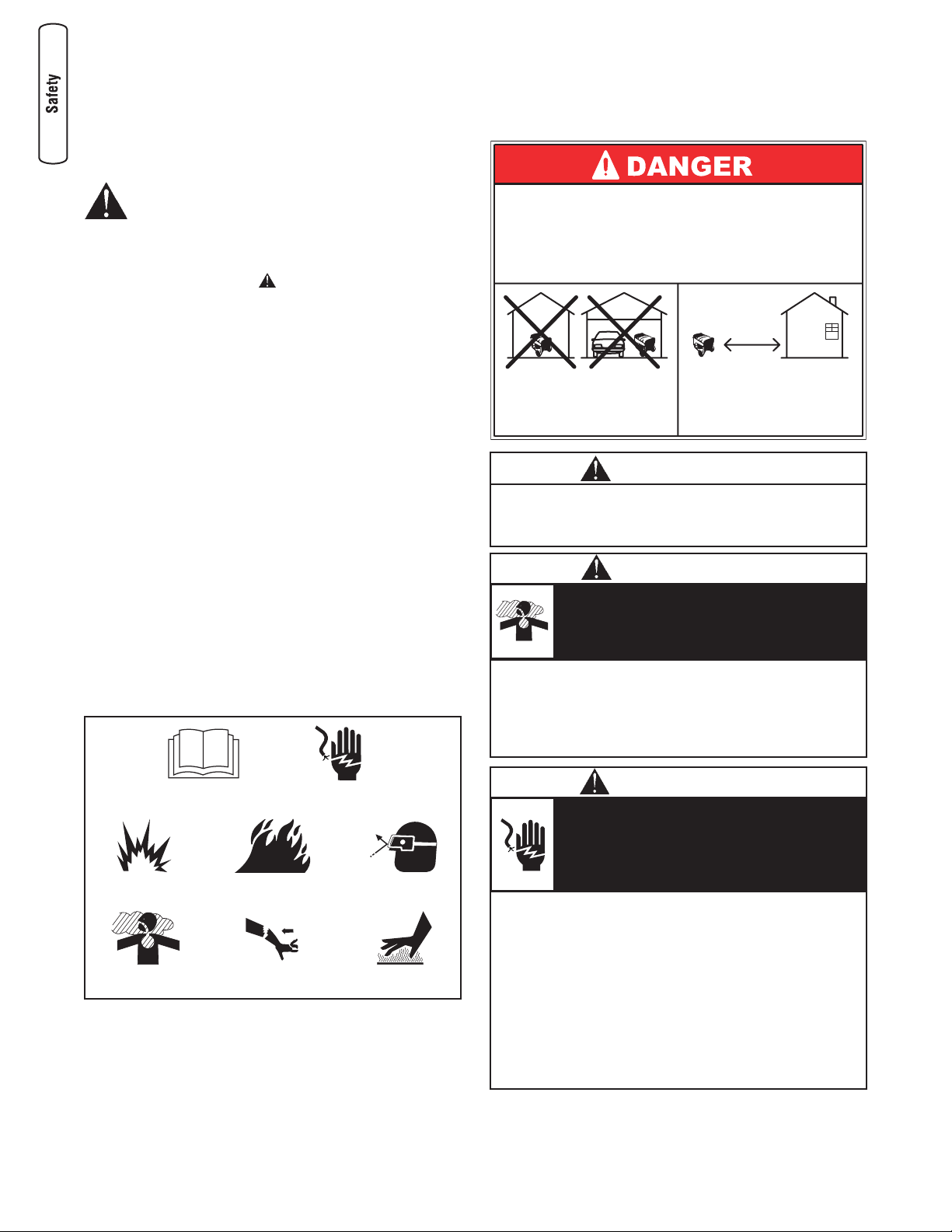
Hazard Symbols and Meanings
• Operate generator ONLY outdoors.
• Keep exhaust gas from entering a confined area through
windows, doors, ventilation intakes or other openings.
• DO NOT operate generator inside any building or enclosure
(even if doors or windows are open), including the generator
compartment of a recreational vehicle (RV).
Running generator gives off carbon
monoxide, an odorless, colorless, poison gas.
Breathing carbon monoxide can cause
nausea, fainting or death.
WARNING
The engine exhaust from this product contains
chemicals known to the State of California to cause
cancer, birth defects, or other reproductive harm.
WARNING
• When using generator for backup power, notify utility
company. Use approved transfer equipment to isolate
generator from electric utility.
• Use a ground fault circuit interrupter (GFCI) in any damp or
highly conductive area, such as metal decking or steel work.
• DO NOT touch bare wires or receptacles.
• DO NOT use generator with electrical cords which are worn,
frayed, bare or otherwise damaged.
• DO NOT operate generator in the rain or wet weather.
• DO NOT handle generator or electrical cords while standing
in water, while barefoot, or while hands or feet are wet.
• DO NOT allow unqualified persons or children to operate or
service generator.
Generator produces hazardous voltage.
Failure to isolate generator from power
utility can result in death or injury to electric
utility workers due to backfeed of electrical
energy.
WARNING
Fire
Explosion
Toxic Fumes
Hot Surface
Electrical Shock
Kickback
Operator’s Manual
Flying Objects
Using a generator indoors WILL KILL YOU
IN MINUTES.
Exhaust contains carbon monoxide, a
poison gas you cannot see or smell.
NEVER use in the home
or in partly enclosed
areas such as garages.
ONLY use outdoors and
far from open windows,
doors, and vents.
3
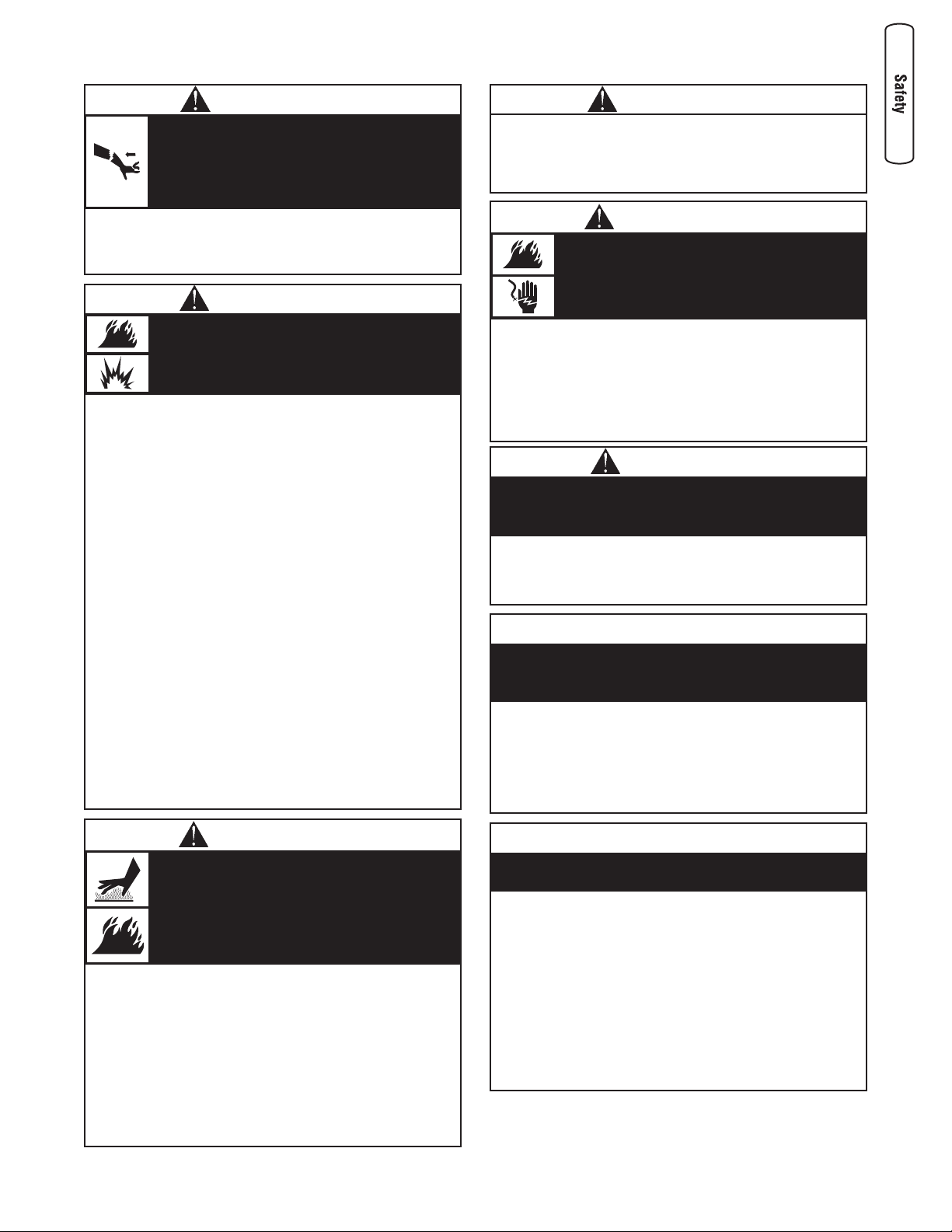
When adjusting or making repairs to your
generator:
• Disconnect the spark plug wire from the spark plug and place
the wire where it cannot contact spark plug.
When testing for engine spark:
• Use approved spark plug tester.
• DO NOT check for spark with spark plug removed.
Unintentional sparking can result in fire or
electric shock.
WARNING
• DO NOT touch hot surfaces and avoid hot exhaust gases.
• Allow equipment to cool before touching.
• Keep at least 5 ft. (152 cm) clearance on all sides of
generator including overhead.
• Code of Federal Regulation (CFR) Title 36 Parks, Forests,
and Public Property require equipment powered by an
internal combustion engine to have a spark arrester,
maintained in effective working order, complying to USDA
Forest service standard 5100-1C or later revision. In the
State of California a spark arrester is required under section
4442 of the California Public resources code. Other states
may have similar laws.
Running engines produce heat.
Temperature of muffler and nearby areas
can reach or exceed 150°F (65°C).
Severe burns can occur on contact.
Exhaust heat/gases can ignite combustibles,
structures or damage fuel tank causing a fire.
WARNING
When adding or draining fuel:
• Turn generator OFF and let it cool at least 2 minutes before
removing fuel cap. Loosen cap slowly to relieve pressure in
tank.
• Fill or drain fuel tank outdoors.
• DO NOT overfill tank. Allow space for fuel expansion.
• If fuel spills, wait until it evaporates before starting engine.
• Keep fuel away from sparks, open flames, pilot lights, heat,
and other ignition sources.
• DO NOT light a cigarette or smoke.
When starting equipment:
• Ensure spark plug, muffler, fuel cap and air cleaner are in
place.
• DO NOT crank engine with spark plug removed.
When operating equipment:
• DO NOT tip engine or equipment at angle which causes fuel
to spill.
• This generator is not for use in mobile equipment or marine
applications.
When transporting or repairing equipment:
• Transport/repair with fuel tank EMPTY or with fuel shutoff
valve OFF.
• Disconnect spark plug wire.
When storing fuel or equipment with fuel in tank:
• Store away from furnaces, stoves, water heaters, clothes
dryers or other appliances that have pilot light or other
ignition source because they can ignite fuel vapors.
Fuel and its vapors are extremely
flammable and explosive.
Fire or explosion can cause severe burns
or death.
WARNING
• This generator does not meet U. S. Coast Guard Regulation
33CFR-183 and should not be used on marine applications.
• Failure to use the appropriate U. S. Coast Guard approved
generator could result in death or serious injury and/or
property damage.
WARNING
• When starting engine, pull cord slowly until resistance is felt
and then pull rapidly to avoid kickback.
• NEVER start or stop engine with electrical devices plugged in
and turned on.
Rapid retraction of starter cord (kickback)
will pull hand and arm toward engine faster
than you can let go.
Broken bones, fractures, bruises or sprains
could result.
WARNING
• See Don’t Overload Generator.
• Start generator and let engine stabilize before connecting
electrical loads.
• Connect electrical loads in OFF position, then turn ON for
operation.
• Turn electrical loads OFF and disconnect from generator
before stopping generator.
Exceeding generators wattage/amperage capacity
can damage generator and/or electrical devices
connected to it.
NOTICE
• Use generator only for intended uses.
• If you have questions about intended use, ask dealer or
contact Briggs and Stratton.
• Operate generator only on level surfaces.
• DO NOT expose generator to excessive moisture, dust, dirt,
or corrosive vapors.
• DO NOT insert any objects through cooling slots.
• If connected devices overheat, turn them off and disconnect
them from generator.
• Shut off generator if:
-electrical output is lost;
-equipment sparks, smokes, or emits flames;
-unit vibrates excessively.
Improper treatment of generator can damage it and
shorten its life.
NOTICE
• DO NOT tamper with governed speed. Generator supplies
correct rated frequency and voltage when running at
governed speed.
• DO NOT modify generator in any way.
Excessively high operating speeds increase risk of
injury and damage to generator.
Excessively low speeds impose a heavy load.
CAUTION
4
BRIGGSandSTRATTON.com
Assembly
Your generator requires some assembly and is ready
for use after it has been properly serviced with the
recommended fuel and oil level is verified.
If you have any problems with the assembly of your
generator, please call the generator helpline at
1-800-743-4115. If calling for assistance, please have
the model, revision, and serial number from the data
tag available. See Generator Controls and Features
for data tag location.
Unpack Generator
1. Set the carton on a rigid, flat surface.
2. Remove everything from carton except generator.
3. Open carton completely by cutting each corner
from top to bottom.
4. Leave generator on carton to install wheel kit.
Shipment Contents
The generator is supplied with:
• Operator’s manual
• Adapter cord set
• Wheel kit
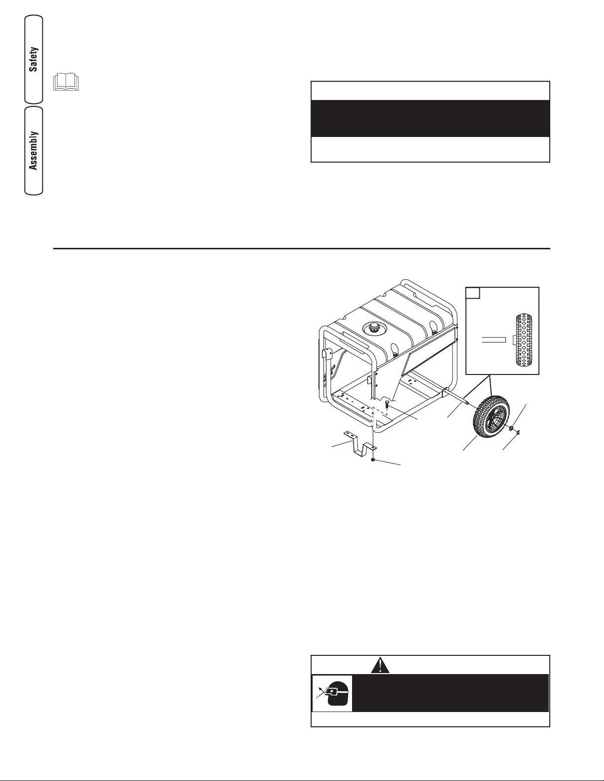
Install Wheel Kit
NOTE: Wheel kit is not intended for over-the-road
use.
You will need the following tools to install these
components:
• 13 mm wrench
• Socket wrench with a 13 mm socket
• Pliers
• Safety glasses
Refer to Figure 1 and install the wheel kit as follows:
1. Tip generator so that engine end is up.
2. Slide axle (A) through both mounting brackets.
3. Place a wheel (B) on each side as shown in
Figure 1a.
4. Place a washer (C) on axle and then place an
e-ring (D) in axle groove.
1a
E
G
D
B
F
A
C
A
B
Figure 1 — Install Wheel Kit
A - Axle
B - Wheel
C - Flat Washer
D - E-Ring
E - Support Leg
F - M8 x 16 mm Capscrews
G - Hex Nuts
Equipment Description
Read this manual carefully and become
familiar with your generator. Know its
applications, its limitations and any hazards
involved.
The generator is an engine–driven, revolving field,
alternating current (AC) generator. It was designed to
supply electrical power for operating compatible
electrical lighting, appliances, tools and motor loads.
The generator’s revolving field is driven at about
3,600 rpm by a single-cylinder engine.
Every effort has been made to ensure that the
information in this manual is both accurate and current.
However, the manufacturer reserves the right to
change, alter or otherwise improve the generator and
this documentation at any time without prior notice.
The Emission Control System for this generator is
warranted for standards set by the Environmental
Protection Agency and the California Air Resources
Board.
• DO NOT exceed the generator’s wattage/amperage capacity.
See Don’t Overload Generator in the Operation section.
Exceeding generators wattage/amperage capacity
can damage generator and/or electrical devices
connected to it.
NOTICE
• Always wear eye protection when installing/removing e-rings.
E-rings can cause eye injury.
E-rings can spring back and become
airborne when installing or removing.
CAUTION
5
5. Install e-ring with pliers, squeezing from top of
e-ring to bottom of axle.
6. Repeat steps 4 and 5 to secure second wheel.
7. Tip generator so that engine side is down.
8. Line up holes in support leg (E) with holes in
generator frame.
9. Attach support leg using 2 capscrews (M8 x 16
mm) (F) and 2 hex nuts (G). Tighten with a
13 mm socket wrench and 13 mm wrench.
10. Return generator to normal operating position
(resting on wheels and support leg).
Add Engine Oil
1. Place generator on a flat, level surface.
2. Clean area around oil fill and remove yellow oil fill
cap.
NOTE: See the section Oil to review oil
recommendations. Verify provided oil bottle is correct
viscosity for current ambient temperature.
3. Using oil funnel (optional), slowly pour contents of
provided oil bottle into oil fill opening.
4. Replace oil fill cap and fully tighten.
Add Fuel
Fuel must meet these requirements:
• Clean, fresh, unleaded gasoline.
• A minimum of 87 octane/87 AKI (91 RON). High
altitude use, see below.
• Gasoline with up to 10% ethanol (gasohol) or up
to 15% MTBE (methyl tertiary butyl ether) is
acceptable.
To protect the fuel system from gum formation, mix in
a fuel stabilizer when adding fuel. See Storage. All
fuel is not the same. If you experience starting or
performance problems after using fuel, switch to a
different fuel provider or change brands. This engine
is certified to operate on gasoline. The emission
control system for this engine is EM (Engine
Modifications).
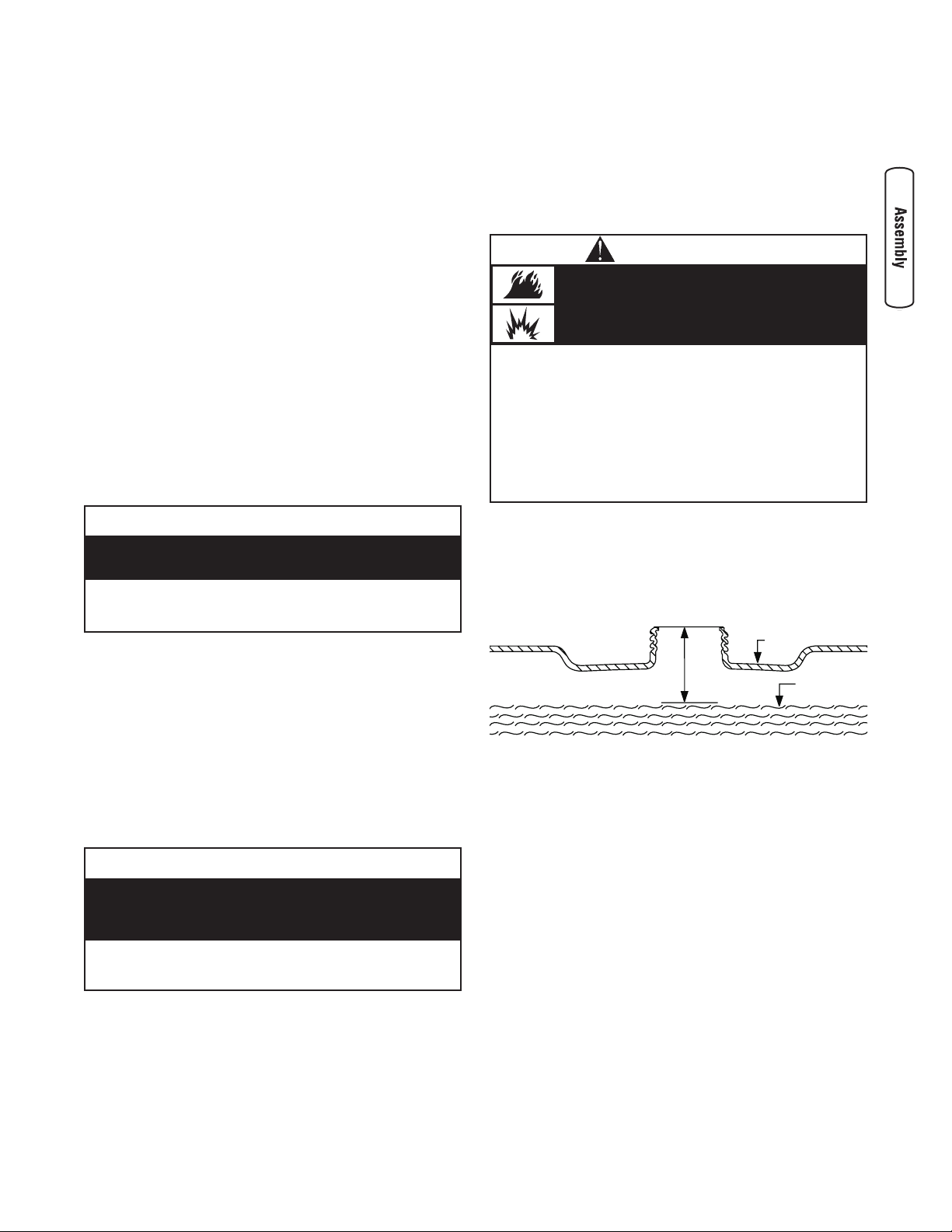
1. Clean area around fuel fill cap, remove cap.
2. Slowly add unleaded gasoline (A) to fuel tank (B).
Be careful not to overfill. Allow at least 1.5" (4 cm)
of tank space (C) for fuel expansion, as shown in
Figure 2.
3. Install fuel cap and let any spilled fuel evaporate
before starting engine.
High Altitude
At higher altitudes (over 5,000 feet), 85 octane/85 AKI
(89 RON) gasoline is recommended. High-altitude use
may require a carburetor jet kit to improve
performance and decrease fuel consumption. See an
Authorized Briggs & Stratton Dealer for more
information.
When adding fuel:
• Turn generator OFF and let it cool at least 2 minutes before
removing fuel cap. Loosen cap slowly to relieve pressure in
tank.
• Fill or drain fuel tank outdoors.
• DO NOT overfill tank. Allow space for fuel expansion.
• If fuel spills, wait until it evaporates before starting engine.
• Keep fuel away from sparks, open flames, pilot lights, heat,
and other ignition sources.
• DO NOT light a cigarette or smoke.
Fuel and its vapors are extremely
flammable and explosive.
Fire or explosion can cause severe burns
or death.
WARNING
Figure 2 — Fuel Expansion
A - Fuel
B - Fuel Tank
C - Tank Space
A
B
C
NOTICE
• DO NOT attempt to crank or start the engine before it has
been properly serviced with the recommended oil. This may
result in an engine failure.
Improper treatment of generator can damage it and
shorten its life.
NOTICE
• DO NOT use unapproved gasoline such as E85.
• DO NOT mix oil in fuel.
• DO NOT modify engine to run on alternate fuels.
Avoid generator damage.
Failure to follow Operator’s Manual for fuel
reccomendations voids warranty.
6
BRIGGSandSTRATTON.com
System Ground
The generator has a system ground that connects the
generator frame components to the ground terminals
on the AC output receptacles. The system ground is
connected to the AC neutral wire (the neutral is
bonded to the generator frame).
Special Requirements
There may be Federal or State Occupational Safety
and Health Administration (OSHA) regulations, local
codes, or ordinances that apply to the intended use of
the generator. Please consult a qualified electrician,
electrical inspector, or the local agency having
jurisdiction:
• In some areas, generators are required to be
registered with local utility companies.
• If the generator is used at a construction site,
there may be additional regulations which must
be observed.
Connecting to a Building’s Electrical
System
Connections for standby power to a building’s
electrical system must be made by a qualified
electrician. The connection must isolate the generator
power from utility power and must comply with all
applicable laws and electrical codes.
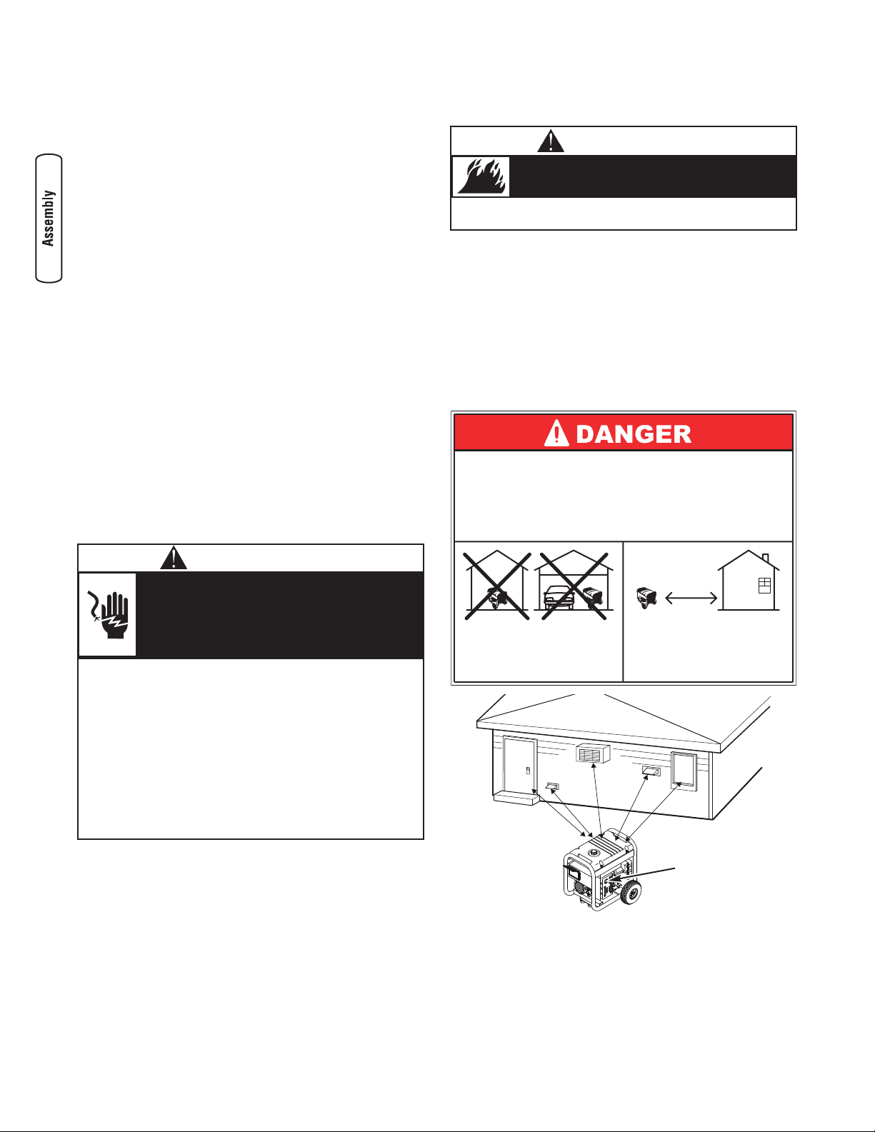
Generator Location
Clearances and Air Movement
Place generator in a well ventilated area, which will
allow for removal of deadly exhaust gas. DO NOT
place generator where exhaust gas could accumulate
and enter inside or be drawn into a potentially
occupied building. Ensure exhaust gas is kept away
from any windows, doors, ventilation intakes, or other
openings that can allow exhaust gas to collect in a
confined area (Figure 3). Prevailing winds and air
currents should be taken into consideration when
positioning generator.
• When using generator for backup power, notify utility
company. Use approved transfer equipment to isolate
generator from electric utility.
• Use a ground fault circuit interrupter (GFCI) in any damp or
highly conductive area, such as metal decking or steel work.
• DO NOT touch bare wires or receptacles.
• DO NOT use generator with electrical cords which are worn,
frayed, bare or otherwise damaged.
• DO NOT operate generator in the rain or wet weather.
• DO NOT handle generator or electrical cords while standing
in water, while barefoot, or while hands or feet are wet.
• DO NOT allow unqualified persons or children to operate or
service generator.
Generator produces hazardous voltage.
Failure to isolate generator from power
utility can result in death or injury to electric
utility workers due to backfeed of electrical
energy.
WARNING
• Keep at least 5 ft. (152 cm) clearance on all sides of
generator including overhead.
Exhaust heat/gases can ignite combustibles,
structures or damage fuel tank causing a fire.
WARNING
A
Figure 3 — Generator Clearance for Typical Generator
A - Exhaust Port
Using a generator indoors WILL KILL YOU
IN MINUTES.
Exhaust contains carbon monoxide, a
poison gas you cannot see or smell.
NEVER use in the home
or in partly enclosed
areas such as garages.
ONLY use outdoors and
far from open windows,
doors, and vents.
7
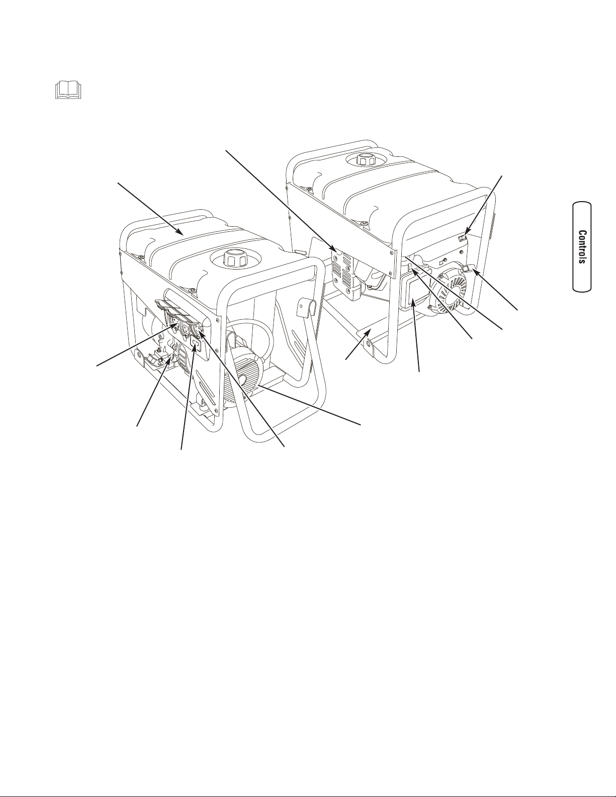
A - 120 Volt AC, 20 Amp, Duplex Receptacles —
May be used to supply electrical power for the
operation of 120 Volt AC, 20 Amp, single phase,
60 Hz electrical, lighting, appliance, tool, and
motor loads.
B - 120/240 Volt AC, 30 Amp Locking Receptacle
— May be used to supply electrical power for the
operation of 120 and/or 240 Volt AC, 30 Amp,
single phase, 60 Hz electrical, lighting, appliance,
tool, and motor loads.
C - Air Cleaner — Protects engine by filtering dust
and debris out of intake air.
D - Choke Lever — Used when starting a cold
engine.
E - Data Tag — Provides model, revision, and serial
number of generator. Please have these readily
available when calling for assistance.
F - Double Pole Circuit Breaker (AC) — A double
pole circuit breaker is provided to protect all the
receptacles and generator against electrical
overload.
G - Fuel Tank — Capacity of five (5) U.S. gallons
(18.9 l).
H - Fuel Valve — Used to turn fuel supply on and off to
engine.
I - Grounding Fastener — Consult your local agency
having jurisdiction for grounding requirements in
your area.
J - Oil Fill — Add engine oil here.
K - Recoil Starter — Used to start the engine.
L - Engine Rocker Switch — Set this switch to “On”
before using recoil starter. Set switch to “Off” to
stop engine.
M - Spark Arrester Muffler — Exhaust muffler lowers
engine noise and is equipped with a spark
arrester screen.
Features and Controls
Read this Operator’s Manual and safety rules before operating your generator.
Compare the illustrations with your generator, to familiarize yourself with the locations of various controls
and adjustments. Save this manual for future reference.
C
B
I
F
J
E
D
K
L
A
G
M
H
8
BRIGGSandSTRATTON.com
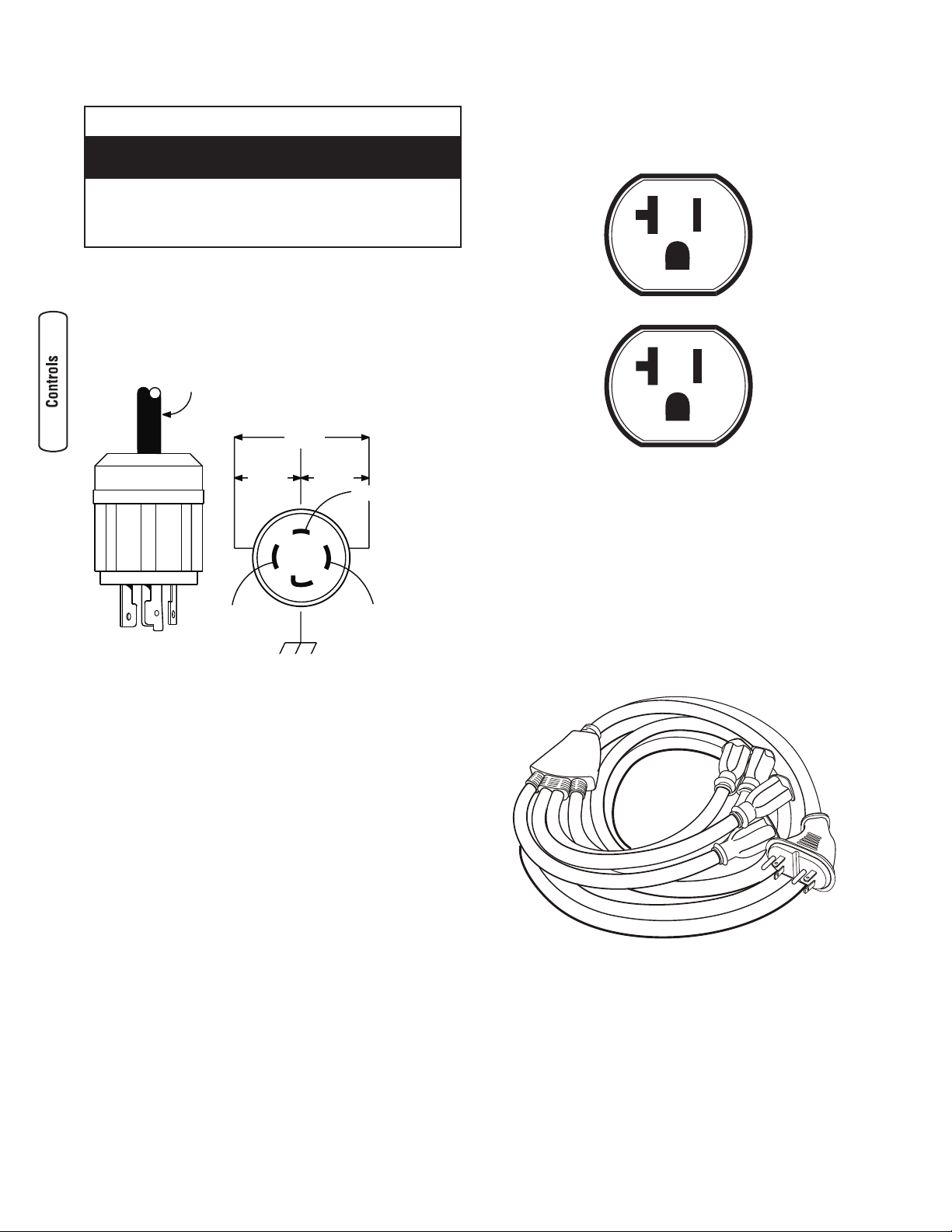
Receptacles
120/240 Volt AC, 30 Amp, Locking Receptacle
Use a NEMA L14-30 plug with this receptacle.
Connect a 4-wire cord set (A) rated for 250 Volt AC
loads at 30 Amps (or greater) (Figure 4). You can use
the same 4-wire cord if you plan to run a 120 Volt
load.
This receptacle powers 120/240 Volt AC, 60 Hz,
single phase loads requiring up to 5,550 watts of
power (5.55 kW) at 23.1 Amps for 240 Volts or two
independent 120 Volt loads at 23.1 Amps each. The
outlet is protected by a double pole rocker switch
circuit breaker.
120 Volt AC, 20 Amp, Duplex Receptacles
Both duplex receptacles (Figure 5) are protected
against overload by a double pole rocker switch circuit
breaker.
Use each receptacle to operate 120 Volt AC, singlephase, 60 Hz electrical loads requiring up to
2,400 watts (2.4 kW) at 20 Amps of current. Use cord
sets that are rated for 125 Volt AC loads at 20 Amps
(or greater). Inspect cord sets before each use.
Generator Adapter Cord Set
The generator comes with a 25' generator adapter
cord set designed to provide two sets of 120 Volt,
20 Amp outlets from one 120 Volt, 20 Amp duplex
receptacle (Figure 6).
The maximum load on each outlet is 20 Amps. The
maximum total load on both black wire outlets or white
stripe wire outlets is 20 Amps.
NOTE: Follow all safety precautions when connecting
any extension cord or device to the generator.
Figure 5 — 120 Volt, 20 Amp Duplex Receptacle
• NEVER attempt to power a device requiring more amperage
than generator or receptacle can supply.
• DO NOT overload the generator. See Don’t Overload
Generator in the Operation section.
Receptacles may be marked with rating value
greater than generator output capacity.
NOTICE
Figure 4 — 120/240 Volt AC, 30 Amp Receptacle
A - 4-Wire Cord Set
B - W (Neutral)
C - X (Hot)
D - Y (Hot)
E - Ground (Green)
A
240V
120V
120V
NEMA L14-30
Figure 6 — Generator Adapter Cord Set
B
C
D
E
9
Operation
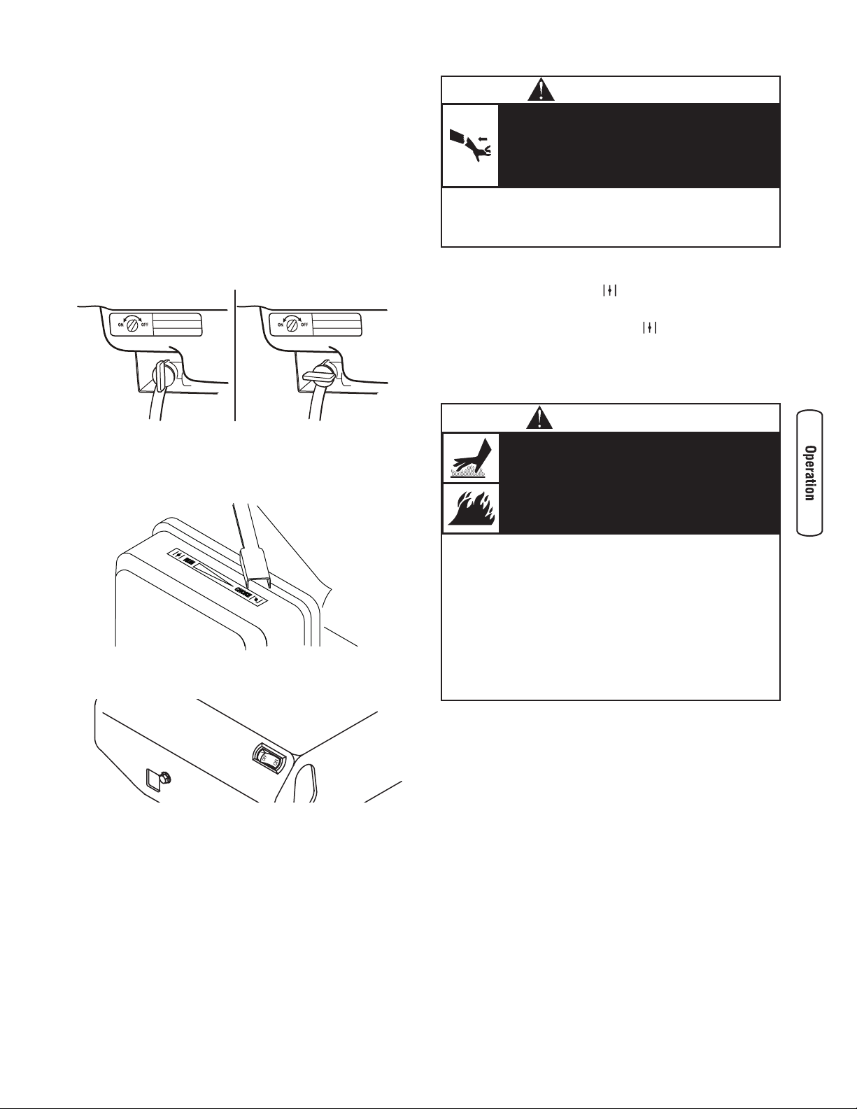
Starting the Engine
Disconnect all electrical loads from the generator. Use
the following start instructions:
1. Make sure unit is on a level surface.
IMPORTANT: Failure to start and operate the unit on
a level surface will cause the unit not to start or shut
down during operation.
2. Turn red fuel valve from “Off” position (A) to “On”
position (B) (Figure 7).
3. Push choke lever to “Choke” position (Figure 8).
4. Push engine rocker switch to “On” (Figure 9).
5. Grasp recoil handle and pull slowly until slight
resistance is felt. Then pull handle rapidly to
overcome compression, prevent kickback, and
start engine.
IMPORTANT: If excessive fuel is present in the
air/fuel mixture causing a “flooded” condition, move
the choke lever to “Run” ( ) position and pull the
handle repeatedly until the engine starts.
6. Move choke lever to “Run” ( ) position a short
distance at a time over several seconds in warm
weather or minutes in cold weather. Let engine
run smoothly before each change. Operate with
choke in “Run” position.
NOTE: If the engine starts after 3 pulls but fails to run,
or if the unit shuts down during operation, make sure
the unit is on a level surface and check for the proper
oil level in the crankcase. This unit may be equipped
with a low oil protection device.
Figure 8 — Choke Lever
Figure 7 — Fuel Valve
A - “Off” Position
B - “On” Position
• DO NOT touch hot surfaces and avoid hot exhaust gases.
• Allow equipment to cool before touching.
• Keep at least 5 ft. (152 cm) clearance on all sides of
generator including overhead.
• Code of Federal Regulation (CFR) Title 36 Parks, Forests,
and Public Property require equipment powered by an
internal combustion engine to have a spark arrester,
maintained in effective working order, complying to USDA
Forest service standard 5100-1C or later revision. In the
State of California a spark arrester is required under section
4442 of the California Public resources code. Other states
may have similar laws.
Running engines produce heat.
Temperature of muffler and nearby areas
can reach or exceed 150°F (65°C).
Severe burns can occur on contact.
Exhaust heat/gases can ignite combustibles,
structures or damage fuel tank causing a fire.
WARNING
• When starting engine, pull cord slowly until resistance is felt
and then pull rapidly to avoid kickback.
• NEVER start or stop engine with electrical devices plugged in
and turned on.
Rapid retraction of starter cord (kickback)
will pull hand and arm toward engine faster
than you can let go.
Broken bones, fractures, bruises or sprains
could result.
WARNING
Figure 9 — Engine Rocker Switch
B
A
10
BRIGGSandSTRATTON.com
Connecting Electrical Loads
1. Let engine stabilize and warm up for a few
minutes after starting.
2. Plug in and turn on the desired 120 and/or
240 Volt AC, single phase, 60 Hz electrical loads.
NOTE:
• DO NOT connect 240 Volt loads to the 120 Volt
duplex receptacles.
• DO NOT connect 3-phase loads to the generator.
• DO NOT connect 50 Hz loads to the generator.
• DO NOT OVERLOAD THE GENERATOR. See
Don’t Overload Generator.
Stopping the Engine
1. Turn OFF and unplug all electrical loads from
generator panel receptacles. NEVER start or stop
engine with electrical devices plugged in and
turned ON.
2. Let engine run at no-load for several minutes to
stabilize internal temperatures of engine and
generator.
3. Push engine rocker switch to “Off” position
(Figure 9).
4. Move fuel valve to “Off” position (A) (Figure 7).
• See Don’t Overload Generator.
• Start generator and let engine stabilize before connecting
electrical loads.
• Connect electrical loads in OFF position, then turn ON for
operation.
• Turn electrical loads OFF and disconnect from generator
before stopping generator.
Exceeding generators wattage/amperage capacity
can damage generator and/or electrical devices
connected to it.
NOTICE
• DO NOT stop engine by moving choke lever to “Choke”
position.
Backfire, fire or engine damage could
occur.
WARNING
11
Don’t Overload Generator
Capacity
You must make sure your generator can supply
enough rated (running) and surge (starting) watts for
the items you will power at the same time. Follow
these simple steps:
1. Select the items you will power at the same time.
2. Total the rated (running) watts of these items. This
is the amount of power your generator must
produce to keep your items running. See Figure 10.
3. Estimate how many surge (starting) watts you will
need. Surge wattage is the short burst of power
needed to start electric motor-driven tools or
appliances such as a circular saw or refrigerator.
Because not all motors start at the same time,
total surge watts can be estimated by adding only
the item(s) with the highest additional surge watts
to the total rated watts from step 2.
Example:
Total Rated (Running) Watts = 3075
Highest Additional Surge Watts = 1800
Total Generator Output Required = 4875
Power Management
To prolong the life of your generator and attached
devices, it is important to take care when adding
electrical loads to your generator. There should be
nothing connected to the generator outlets before
starting its engine. The correct and safe way to
manage generator power is to sequentially add loads
as follows:
1. With nothing connected to the generator, start the
engine as described in this manual.
2. Plug in and turn on the first load, preferably the
largest load you have.
3. Permit the generator output to stabilize (engine
runs smoothly and attached device operates
properly).
4. Plug in and turn on the next load.
5. Again, permit the generator to stabilize.
6. Repeat steps 4 and 5 for each additional load.
NEVER add more loads than the generator capacity.
Take special care to consider surge loads in generator
capacity, as described above.
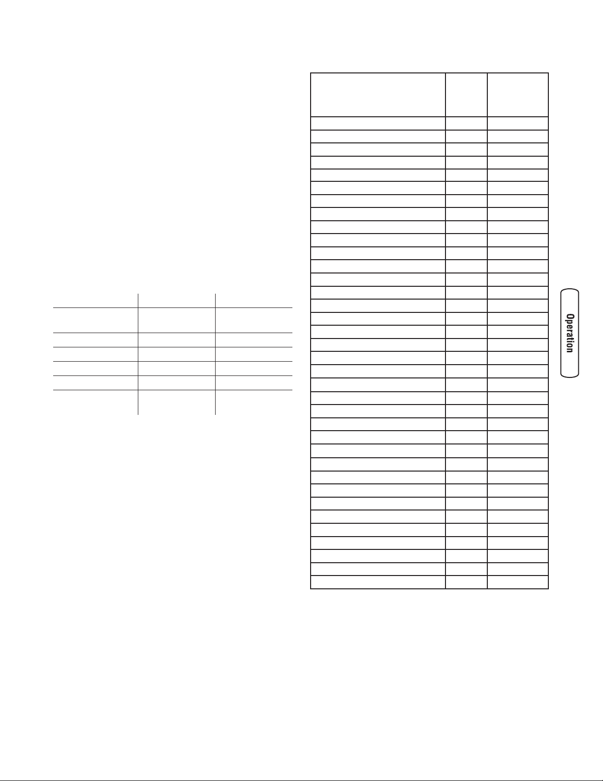
* Wattages listed are approximate only. Check tool or
appliance for actual wattage.
Tool or Appliance Watts (Starting) Watts
Window Air
Conditioner
1200 1800
Refrigerator 800 1600
Deep Freezer 500 500
Television 500 —
Light (75 Watts) 75 —
3075 Total
Running Watts
1800 Highest
Surge Watts
Tool or Appliance
Rated*
(Running)
Watts
Additional
Surge
(Starting)
Watts
Essentials
Light Bulb - 75 watt 75 Deep Freezer 500 500
Sump Pump 800 1200
Refrigerator/Freezer - 18 Cu. Ft. 800 1600
Water Well Pump - 1/3 HP 1000 2000
Heating/Cooling
Window AC - 10,000 BTU 1200 1800
Window Fan 300 600
Furnace Fan Blower - 1/2 HP 800 1300
Kitchen
Microwave Oven - 1000 Watt 1000 Coffee Maker 1500 Electric Stove - Single Element 1500 Hot Plate 2500 -
Family Room
DVD/CD Player 100 VCR 100 Stereo Receiver 450 Color Television - 27” 500 Personal Computer w/17” monitor 800 -
Other
Security System 180 AM/FM Clock Radio 300 Garage Door Opener - 1/2 HP 480 520
Electric Water Heater - 40 Gallon 4000 -
DIY/Job Site
Quartz Halogen Work Light 1000 Airless Sprayer - 1/3 HP 600 1200
Reciprocating Saw 960 960
Electric Drill - 1/2 HP 1000 1000
Circular Saw - 7 1/4” 1500 1500
Miter Saw - 10” 1800 1800
Table Planer - 6” 1800 1800
Table Saw/Radial Arm Saw - 10” 2000 2000
Air Compressor - 1-1/2 HP 2500 2500
Figure 10 — Wattage Reference Guide
12
BRIGGSandSTRATTON.com
General Recommendations
Regular maintenance will improve the performance
and extend the life of the generator. See any
authorized Briggs & Stratton dealer for service.
The generator’s warranty does not cover items that
have been subjected to operator abuse or negligence.
To receive full value from the warranty, the operator
must maintain the generator as instructed in this
manual.
Some adjustments will need to be made periodically
to properly maintain your generator.
All service and adjustments should be made at least
once each season. Follow the requirements in the
Maintenance Schedule chart above.
NOTE: Once a year you should clean or replace the
spark plug and replace the air filter. A new spark plug
and clean air filter assure proper fuel-air mixture and
help your engine run better and last longer.
Emissions Control
Maintenance, replacement, or repair of the emissions
control devices and systems may be performed by
any non-road engine repair establishment or
individual. See Emissions Control System Warranty in
the Warranties section.
Maintenance
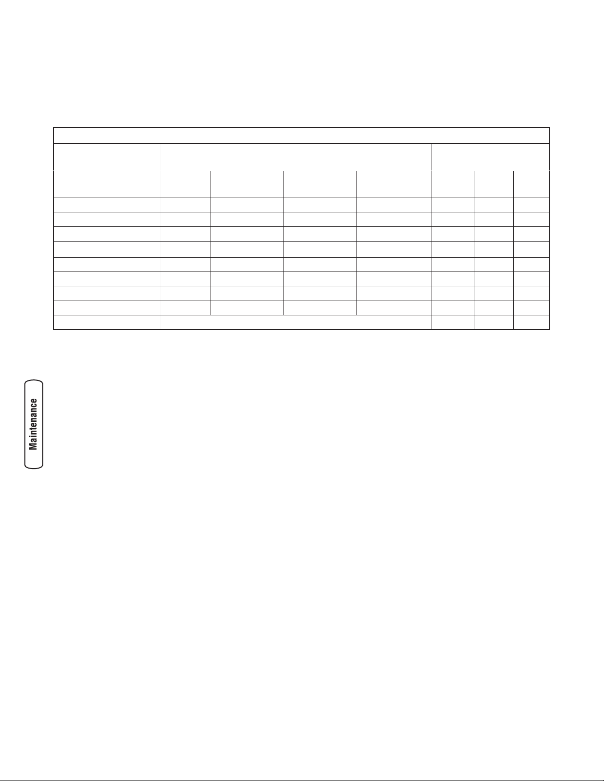
Maintenance Schedule
Follow the hourly or calendar intervals, whichever occurs first. More frequent service is required when operating
in adverse conditions noted below.
1
Change oil after the first (5) operating hours and every 50 hours or every year, whichever occurs first,
thereafter. Change oil sooner when operating under dirty or dusty conditions.
2
Replace more often under dirty or dusty conditions.
Maintenance Schedule - Fill in Dates as You Complete Regular Service
Service Dates Service Dates
Maintenance Task
Before
Each Use
Every 25 Hours
or Yearly
Every 50 Hours
or Yearly
Every 100
Hours or Yearly
Clean debris
X
Check oil level
X
Change engine oil
X
1
Service air cleaner
X
2
Service spark plug
X
Service spark arrester
X
Clean cooling system
X
2
Check valve clearance
X
Prepare for storage
If unit is to remain idle for longer than 30 days.
13
Generator Maintenance
Generator maintenance consists of keeping the unit
clean and dry. Operate and store the unit in a clean
dry environment where it will not be exposed to
excessive dust, dirt, moisture, or any corrosive
vapors. Cooling air slots in the generator must not
become clogged with snow, leaves, or any other
foreign material.
NOTE: DO NOT use water or other liquids to clean
generator. Liquids can enter engine fuel system,
causing poor performance and/or failure to occur. In
addition, if liquid enters generator through cooling air
slots, some of the liquid will be retained in voids and
cracks of the rotor and stator winding insulation.
Liquid and dirt buildup on the generator internal
windings will eventually decrease the insulation
resistance of these windings.
Cleaning
Daily or before use, look around and underneath the
generator for signs of oil or fuel leaks. Clean
accumulated debris from inside and outside the
generator. Keep the linkage, spring and other engine
controls clean. Keep the area around and behind the
muffler free from any combustible debris. Inspect
cooling air slots and openings on generator. These
openings must be kept clean and unobstructed.
Engine parts should be kept clean to reduce the risk
of overheating and ignition of accumulated debris:
• Use a damp cloth to wipe exterior surfaces clean.
• Use a soft bristle brush to loosen caked on dirt or
oil.
• Use a vacuum cleaner to pick up loose dirt and
debris.
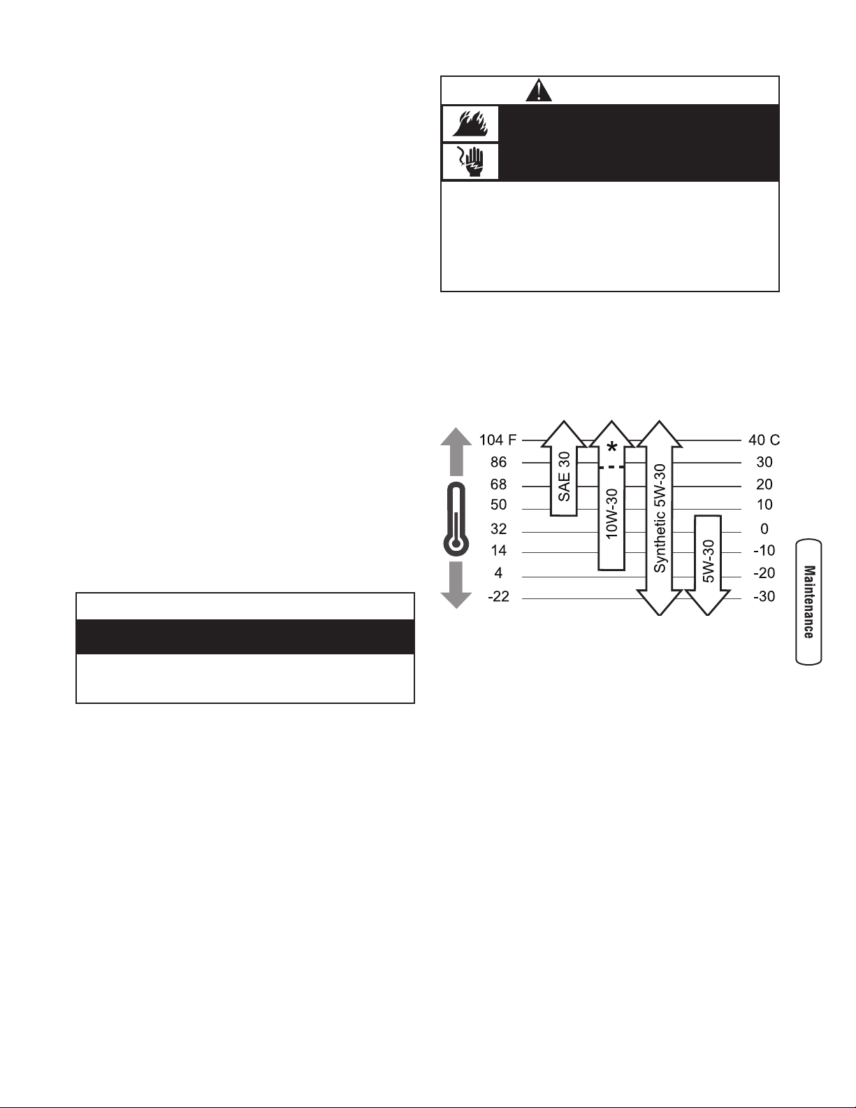
Oil
Oil Recommendations
NOTE: When adding oil to the engine crankcase, use a
high quality detergent oil classified “For Service SF,
SG, SH, SJ” or higher. DO NOT use special additives.
1. Choose a viscosity according to the table below.
* Check oil level frequently at higher temperatures.
NOTE: Synthetic oil meeting ILSAC GF-2, API
certification mark and API service symbol with “SJ/CF
ENERGY CONSERVING” or higher, is an acceptable
oil at all temperatures. Use of synthetic oil does not
alter required oil change intervals.
When adjusting or making repairs to your
generator:
• Disconnect the spark plug wire from the spark plug and place
the wire where it cannot contact spark plug.
When testing for engine spark:
• Use approved spark plug tester.
• DO NOT check for spark with spark plug removed.
Unintentional sparking can result in fire or
electric shock.
WARNING
• DO NOT expose generator to excessive moisture, dust, dirt,
or corrosive vapors.
• DO NOT insert any objects through cooling slots.
Improper treatment of generator can damage it and
shorten its life.
NOTICE
 Loading...