

Page 1
Installation & Start-Up Manual
30000 Series
Liquid-Cooled
Home Generator System
Manual No. 205052GS Rev. A (01/08/2008)
Page 2
Thank you for purchasing this quality-built Briggs & Stratton home generator. We’re pleased that you’ve placed your
confidence in the Briggs & Stratton brand. When operated and maintained according to the instructions in the operator’s
manual, your Briggs & Stratton home generator will provide many years of dependable service.
This manual contains safety information to make you aware of the hazards and risks associated with home generator systems
and how to avoid them. This home generator system is designed and intended only for use as an optional home standby
system that provides an alternate source of electric power and to serve loads such as heating, refrigeration systems, and
communication systems that, when stopped during any power outage, could cause discomfort or inconvenience. This product
is not intended for any other purpose and does not qualify for emergency standby as defined by NFPA 70 (NEC).
This home generator requires professional installation before use. This installation manual provides full information. Follow
the instructions completely. Save these instructions for future reference.
Where to Find Us
You never have to look far to find Briggs & Stratton support and service for your generator. Consult your Yellow Pages.
There are thousands of Briggs & Stratton authorized service dealers worldwide who provide quality service. You can
also contact Briggs & Stratton Customer Service by phone at (800) 743-4115, or use the Service Center Locator at
BRIGGSandSTRATTON.COM, which provides a list of Briggs & Stratton Authorized Dealers.
Date of Purchase
Generator
Model Number
Model Revision
Serial Number
Engine
Model Number
Serial Number
Briggs & Stratton Power Products Group, LLC
900 North Parkway
Jefferson, WI 53549
Copyright © 2008 Briggs & Stratton Power Products Group, LLC.
All rights reserved. No part of this material may be reproduced or
transmitted in any form by any means without the express written
permission of Briggs & Stratton Power Products Group, LLC.
Page 3
Table of Contents
Safety Rules . . . . . . . . . . . . . . . . . . . . . . . . . . . . . . . . . . . 4
Installation . . . . . . . . . . . . . . . . . . . . . . . . . . . . . . . . . . . . 7
Installer Responsibilities . . . . . . . . . . . . . . . . . . . . . . . . . . . . . . . . . . . . . . . 7
Delivery Inspection. . . . . . . . . . . . . . . . . . . . . . . . . . . . . . . . . . . . . . . . . . . . 7
Shipment Contents. . . . . . . . . . . . . . . . . . . . . . . . . . . . . . . . . . . . . . . . . . . . 7
Home Generator Location . . . . . . . . . . . . . . . . . . . . . . . . . . . . . . . . . . . . . .8
Access Doors. . . . . . . . . . . . . . . . . . . . . . . . . . . . . . . . . . . . . . . . . . . . . . . 10
The Gaseous Fuel System . . . . . . . . . . . . . . . . . . . . . . . . . . . . . . . . . . . . . 10
Fuel Consumption . . . . . . . . . . . . . . . . . . . . . . . . . . . . . . . . . . . . . . . . . . . 12
System Connectors . . . . . . . . . . . . . . . . . . . . . . . . . . . . . . . . . . . . . . . . . . 13
Grounding the Generator . . . . . . . . . . . . . . . . . . . . . . . . . . . . . . . . . . . . . . 14
Utility Circuit Connection . . . . . . . . . . . . . . . . . . . . . . . . . . . . . . . . . . . . . . 14
System Control Panel. . . . . . . . . . . . . . . . . . . . . . . . . . . . . . . . . . . . . . . . . 15
Final Installation Considerations . . . . . . . . . . . . . . . . . . . . . . . . . . . . . . . . 15
Fuel Supply System . . . . . . . . . . . . . . . . . . . . . . . . . . . . . . . . . . . . . . . . . . 16
Initial Start-up (No Load). . . . . . . . . . . . . . . . . . . . . . . . . . . . . . . . . . . . . . 16
Fuel Conversion . . . . . . . . . . . . . . . . . . . . . . . . . . . . . . . . . . . . . . . . . . . . . 16
Schematic/Wiring Diagram . . . . . . . . . . . . . . . . . . . . . . . . . . . . . . . . . . . . 18
Controls . . . . . . . . . . . . . . . . . . . . . . . . . . . . . . . . . . . . . 19
Operation . . . . . . . . . . . . . . . . . . . . . . . . . . . . . . . . . . . . 19
Automatic Operation Sequence . . . . . . . . . . . . . . . . . . . . . . . . . . . . . . . . . 19
Setting Exercise Timer . . . . . . . . . . . . . . . . . . . . . . . . . . . . . . . . . . . . . . . . 19
Installation Inspection . . . . . . . . . . . . . . . . . . . . . . . . . . . . . . . . . . . . . . . . 19
FrançaisEspañol
3
Page 4
Save These Instructions
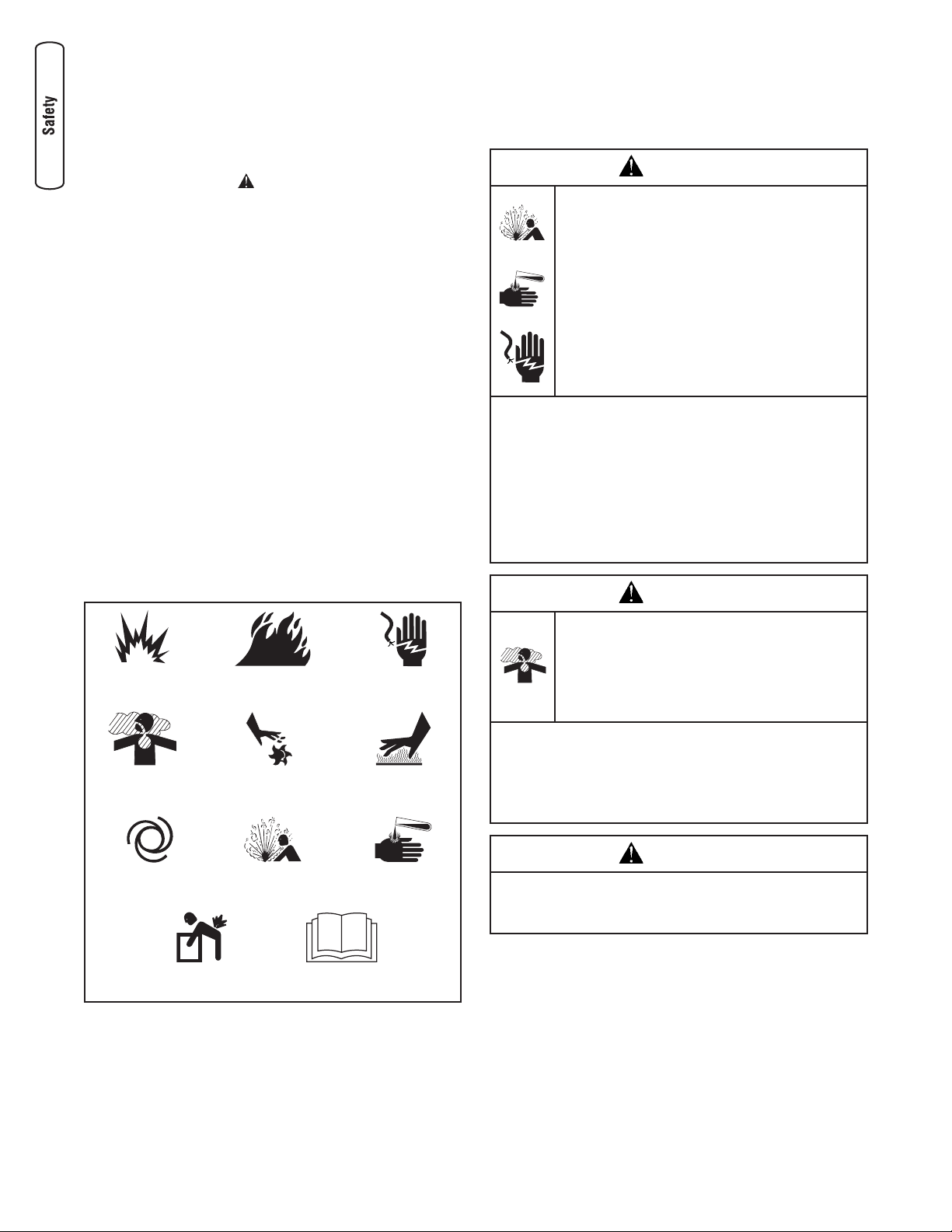
Safety Rules
The safety alert symbol ( ) is used with a signal word
(DANGER, CAUTION, WARNING), a pictorial and/or a safety
message to alert you to hazards. DANGER indicates a hazard
which, if not avoided, will result in death or serious injury.
WARNING indicates a hazard which, if not avoided, could
result in death or serious injury. CAUTION indicates a hazard
which, if not avoided, might result in minor or moderate
injury. NOTICE indicates a situation that could result in
equipment damage. Follow safety messages to avoid or
reduce the risk of injury or death.
This manual contains installation, startup and adjustment
instructions for a home generator that supplies 120/240 Volt,
single phase, 60Hz devices. The home generator may be
operated on LP vapor or natural gas fuel. Separate engine
and generator operator’s manuals are supplied that contain
operating and maintenance instructions for this system.
Every effort has been made to ensure that the information
in this manual is both accurate and current. However, the
manufacturer reserves the right to change, alter or otherwise
improve the system at any time without prior notice.
Hazard Symbols and Meanings
WARNING
Storage batteries give off explosive hydrogen
gas during recharging.
Slightest spark will ignite hydrogen and cause
explosion.
Battery electrolyte fluid contains acid and is
extremely caustic.
Contact with battery contents will cause severe
chemical burns.
A battery presents a risk of electrical shock and
high short circuit current.
DO NOT dispose of battery in a fire.
•
DO NOT allow any open flame, spark, heat, or lit cigarette
•
during and for several minutes after charging a battery.
DO NOT open or mutilate the battery.
•
Wear protective goggles, rubber apron, and rubber
•
gloves.
Remove watches, rings, or other metal objects.
•
Use tools with insulated handles.
•
WARNING
Explosion
Toxic Fumes
Lift Hazard
Fire
Rotating Parts
Read Manual
Electrical Shock
Hot Surface
Chemical BurnExplosive PressureAuto Start
Running engine gives off carbon monoxide, an
odorless, colorless, poison gas.
Breathing carbon monoxide can cause
headache, fatigue, dizziness, vomiting,
confusion, seizures, nausea, fainting or death.
Operate generator ONLY outdoors.
•
Install a battery operated carbon monoxide alarm near
•
the bedrooms.
Keep exhaust gas from entering a confined area through
•
windows, doors, ventilation intakes, or other openings.
WARNING
The engine exhaust from this product contains chemicals
known to the State of California to cause cancer, birth
defects, or other reproductive harm.
4 BRIGGSandSTRATTON.COM
Page 5
WARNING
WARNING
Generator produces hazardous voltage.
Failure to properly ground generator can result
in electrocution.
Failure to isolate generator from power utility
can result in death or injury to electric utility
workers due to backfeed of electrical energy.
When using generator for backup power, notify utility
•
company.
DO NOT touch bare wires or receptacles.
•
DO NOT handle generator or electrical cords while
•
standing in water, while barefoot, or while hands or feet
are wet.
If you must work around a unit while it is operating,
•
stand on an insulated dry surface to reduce shock
hazard.
DO NOT allow unqualified persons or children to operate
•
or service generator.
In case of an accident caused by electrical shock,
•
immediately shut down the source of electrical power
and contact the local authorities. Avoid direct contact
with the victim.
Despite the safe design of the home generator, operating
•
this equipment imprudently, neglecting its maintenance
or being careless can cause possible injury or death.
Remain alert at all times while working on this
•
equipment. Never work on the equipment when you are
physically or mentally fatigued.
Before performing any maintenance on the generator,
•
disconnect the battery cable indicated by a NEGATIVE,
NEG or (-) first. When finished, reconnect that cable last.
After your home generator is installed, the generator
•
may crank and start without warning any time there is
a power failure. To prevent possible injury, always set
the generator’s system switch to OFF AND remove the
15 Amp fuse BEFORE working on the equipment.
Propane and Natural Gas are extremely
flammable and explosive.
Fire or explosion can cause severe burns or
death.
Install the fuel supply system according to applicable
•
fuel-gas codes.
Before placing the home generator into service, the fuel
•
system lines must be properly purged and leak tested.
After the generator is installed, you should inspect the
•
fuel system periodically.
NO leakage is permitted.
•
DO NOT operate engine if smell of fuel is present or other
•
explosive conditions exist.
DO NOT smoke around the generator. Wipe up any oil
•
spills immediately. Ensure that no combustible materials
are left in the generator compartment. Keep the area near
the generator clean and free of debris.
WARNING
Hazardous Voltage
Contact with power lines can cause electric
shock or burn.
Lifting Hazard / Heavy Object
Can cause muscle strain or back injury.
DO NOT contact any power lines when using required
•
lifting/hoisting equipment.
DO NOT lift or move generator without assistance.
•
Use lifting pipes or straps as described in Lifting the
•
Generator. The unit may shift during movement, which
can cause injury.
DO NOT lift unit by roof as damage to generator will
•
occur.
5
Page 6
WARNING
Contact with muffler area can result in serious
burns.
Exhaust heat/gases can ignite combustibles or
structures causing a fire.
DO NOT touch hot parts and AVOID hot exhaust gases.
•
Allow equipment to cool before touching.
•
DO NOT install the generator closer than 5 feet (1.5m)
•
from any combustibles or structures with combustible
walls having a fire resistance rating of less than 1 hour.
Code of Federal Regulation (CFR) Title 36 Parks, Forests,
•
and Public Property require equipment powered by an
internal combustion engine to have a spark arrester,
maintained in effective working order, complying to
USDA Forest service standard 5100-1C or later revision.
In the State of California a spark arrester is required
under section 4442 of the California Public resources
code. Other states may have similar laws.
WARNING
Starter and other rotating parts can entangle
hands, hair, clothing, or accessories.
NEVER operate generator without protective housing or
•
covers.
DO NOT wear loose clothing, jewelry or anything that
•
may be caught in the starter or other rotating parts.
Tie up long hair and remove jewelry.
•
CAUTION
Excessively high operating speeds increase risk of injury
and damage to generator.
Excessively low speeds impose a heavy load.
DO NOT tamper with governed speed. Generator supplies
•
correct rated frequency and voltage when running at
governed speed.
DO NOT modify generator in any way.
•
NOTICE
Exceeding generators wattage/amperage capacity can
damage generator and/or electrical devices connected to
it.
See Essential Circuits in Operator’s manual.
•
Start generator and let engine stabilize before connecting
•
electrical loads.
NOTICE
Improper treatment of generator can damage it and
shorten its life.
Use generator only for intended uses.
•
If you have questions about intended use, ask dealer or
•
contact Briggs and Stratton.
Operate generator only on level surfaces.
•
Adequate, unobstructed flow of cooling and ventilating
•
air is critical to correct generator operation.
The Coolant Fill, Battery and Control Panel doors must be
•
installed whenever the unit is running.
DO NOT expose generator to excessive moisture, dust,
•
dirt, or corrosive vapors.
Despite the safe design of the home generator, operating
•
this equipment imprudently, neglecting its maintenance or
being careless can cause possible injury or death.
DO NOT start engine with air cleaner or air cleaner cover
•
removed.
DO NOT insert any objects through cooling slots.
•
DO NOT use the generator or any of its parts as a step.
•
Stepping on the unit can cause stress and break parts.
This may result in dangerous operating conditions from
leaking exhaust gases, fuel leakage, oil leakage, etc.
If connected devices overheat, turn them off and
•
disconnect them from generator.
Shut off generator if:
•
-electrical output is lost;
-equipment sparks, smokes, or emits flames;
-unit vibrates excessively.
6 BRIGGSandSTRATTON.COM
Page 7

Installation
Equipment Description
This product is intended for use as an optional home
generator system which provides an alternate source
of electric power and to serve loads such as heating,
refrigeration systems, and communication systems that,
when stopped during any power outage, could cause
discomfort or inconvenience. This product does not qualify
for emergency standby as defined by NFPA 70 (NEC).
Customer Responsibilities
• Read and follow the instructions given in the Operator’s
Manual, especially the section regarding selecting
essential circuits.
• Follow a regular schedule in maintaining, caring for
and using your home generator, as specified in the
Operator’s Manual.
Installer Responsibilities
• Read and observe the safety rules.
• Install only an UL approved transfer switches that is
compatible with the home generator.
• Read and follow the instructions given in this
Installation and Start-up Manual.
IMPORTANT: The system is equipped with a water heater
that is activated when ambient temperature is less than 80°F
AND utility power is present at the transfer switch.
Delivery Inspection
After removing the carton, carefully inspect the home
generator for any damage that may have occurred during
shipment.
IMPORTANT: If loss or damage is noted at time of delivery,
have the person(s) making delivery note all damage on the
freight bill and affix his signature under the consignor’s
memo of loss or damage. If loss or damage is noted after
delivery, separate the damaged materials and contact the
carrier for claim procedures. Missing or damaged parts are
not warranted.
Shipment Contents
The home generator system is supplied with:
• Home generator
• Fully-serviced coolant system
• Fully-serviced oil/lubricating system
• UL569/CSA8.3-listed flexible fuel hook-up
• Installation and start-up manual
• Operator’s manual
• Engine operator’s manual
• Installation checklist
• Two access door keys
• One spare 15A fuse
• 10 Pole control panel connector
• Remote LED indicator kit (red LED/plate/screws)
Unpacking Precautions
The unit is shipped ready for installation on a prepared
reinforced cement slab or engineered base. Avoid damage
from dropping, bumping, collision, etc. Store and unpack
carton with the proper side up, as noted on the shipping
carton.
Not Supplied:
• 650 CCA starting battery (NOT deep-cycle)
• Connecting wire and conduit
• Fuel supply valves/plumbing
Required Specialty Tools/Equipment
• Two 60” lengths of 2” Schedule 40 pipe (NOT conduit)
• Lifting straps, chains or cables
• Hole punches for 7 ga steel
• Torque screwdriver, 5 to 50 inch-pound range
• Ignition Timing Light
• Air Fuel Ratio Meter (O2 Sensor and Analyzer)
7
Page 8
Home Generator Location
Before installing generator, consult with homeowner and convey
the following guidelines which may affect the desired location.
WARNING
Exhaust heat / gasses can ignite combustibles
or structures causing a fire.
DO NOT install the generator closer than 5 feet (1.5m)
•
from any combustibles or structures with combustible
walls having a fire resistance rating of less than 1 hour.
Generator Location
Install generator outdoors in an area which will not
accumulate deadly exhaust gas. DO NOT install generator
where exhaust gas could accumulate and enter inside or be
drawn into a potentially occupied building. Ensure exhaust
gas is kept away from any windows, doors, ventilation intakes
or other openings that can allow exhaust gas to collect in a
confined area. Prevailing winds and air currents should be
taken into consideration when positioning generator.
WARNING
• Install the generator as close as possible to the transfer
switch and fuel supply to reduce the length of wiring,
conduit, and piping.
IMPORTANT: Laws or local codes may regulate the distance
to the fuel supply.
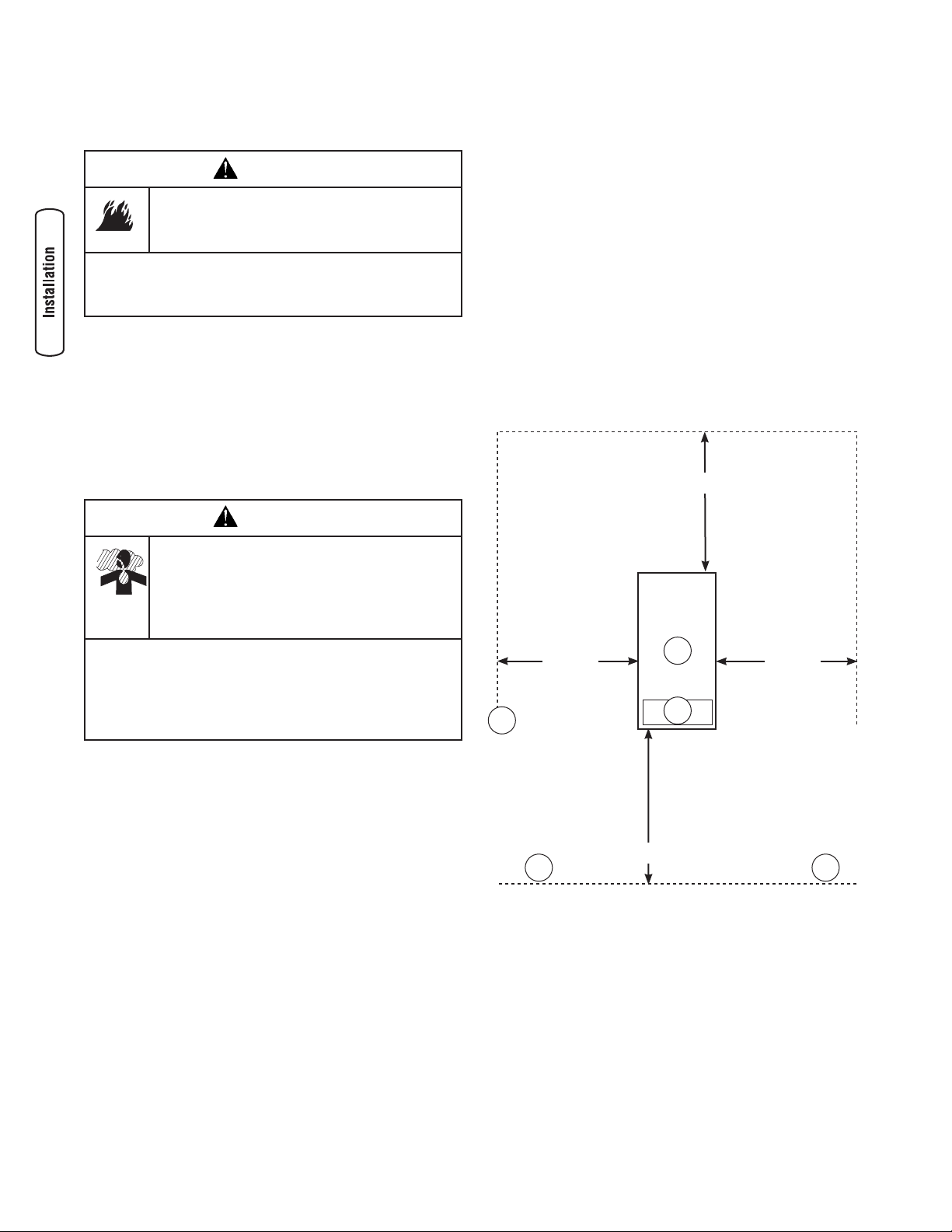
The Minimum clearances from aerial view of generator (A) to
combustible (C, D) materials is shown below.
• These distances are provided to give generator location
guidance relative ONLY to combustibles, generator
cooling, and maintenance.
• The minimum distances in the figure are as shown.
All four sides of the generator cannot be enclosed
or restricted, even if the minimum distances are
maintained. DO NOT connect (C) to (D)
• A roof cannot be used.
• Exhaust (B) is directed out the top of the generator and
must not be allowed to accumulate.
5’ (1.5m)
Running engine gives off carbon monoxide, an
odorless, colorless, poison gas.
Breathing carbon monoxide can cause
headache, fatigue, dizziness, vomiting,
confusion, seizures, nausea, fainting, or death.
Operate generator ONLY outdoors.
•
Install a battery operated carbon monoxide alarm near
•
the bedrooms.
Keep exhaust gas from entering a confined area through
•
windows, doors, ventilation intakes, or other openings.
General Location Guidelines
• Install the unit outdoors ONLY.
• Place the unit on a prepared concrete slab that is flat,
level, and has provisions for water drainage.
• Install the unit in a location where sump pump
discharge, rain gutter down spouts, roof run-off,
landscape irrigation, or water sprinklers will not flood
the unit or spray the enclosure and enter any air inlet or
outlet openings.
• Install the unit where the location of any services such
as phone, electrical, fuel, air conditioning, irrigation,
including covered, concealed and underground services
will not be affected or obstructed.
• Install the unit where air inlet and outlet openings will
not become obstructed by leaves, grass, snow, etc. If
prevailing winds will cause blowing or drifting, you may
need to construct a windbreak to protect the unit.
5’ (1.5m) 5’ (1.5m)
C
5’ (1.5m)
D
A Home Standby Generator
B Engine Exhaust (exits vertically from enclosure)
C Combustible Material or Structure with a Fire
Resistance Rating of less than 1 hour.
D Any structure or material. DO NOT connect (C) to (D).
A
B
D
8 BRIGGSandSTRATTON.COM
Page 9
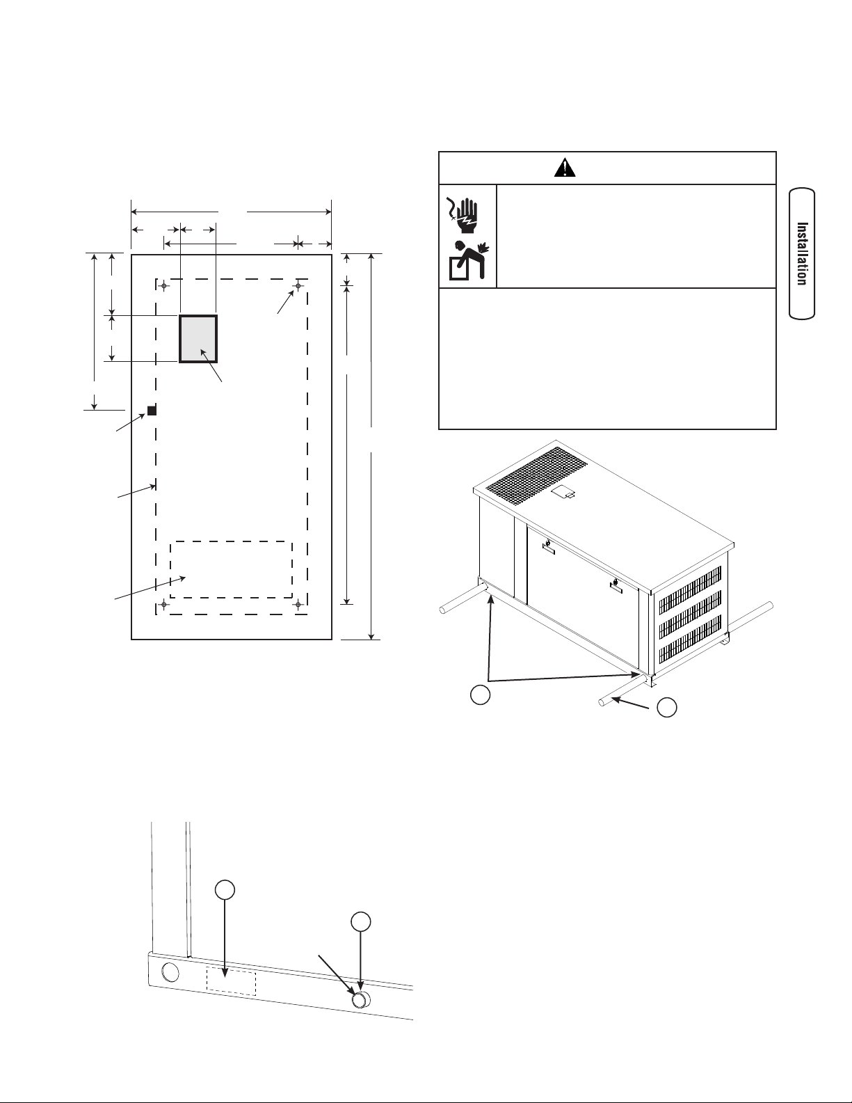
Concrete Slab
49”
14.25”
94”
78”
38”
9.5”
7”
7.38”
34.25”
10.5”
8”
At the appropriate location, construct a concrete slab (28 day
compression strength of 3000 psi (200 MPa)) minimum
5 inches thick and 6 inches wider than the enclosure on
all sides. Strengthen slab with No. 6 reinforcing bars (on
12” centers) or 8 ga. steel wire fabric (6” centers). Avoid
placing reinforcement in entrance stub-up area.
Anchor bolt
position
(4 places)
Power Cable
Stub-in
location
Fuel Inlet
Port
Lifting the Generator
The generator weighs more than 1,700 pounds. Proper tools,
equipment and qualified personnel should be used in all
phases of handling and moving the generator.
WARNING
Hazardous Voltage
Contact with power lines can cause electric
shock or burn.
Lifting Hazard / Heavy Object
Can cause muscle strain or back injury.
DO NOT contact any power lines when using required
•
lifting/hoisting equipment.
DO NOT lift or move generator without assistance.
•
Use lifting pipes or straps as described in Lifting the
•
Generator. The unit may shift during movement, which
can cause injury.
DO NOT lift unit by roof as damage to generator will
•
occur.
Enclosure
Base
Exhaust
Opening
(shown for
reference)
Slab Top VIew
Attach unit to slab with 5/16” diameter (minimum) masonry
anchor bolts long enough to retain the unit.
Electrical and Fuel Inlet Locations
A through-slab power cable stub-up is preferred (see above).
If stub-up’s are not used, (A) indicates the recommended
location for punching holes for attaching power conduit. The
fuel inlet connector (B) is shown for reference.
A
A
B
Two 60” lengths of 2” Schedule 40 pipe (B), supplied by the
installer, are required to lift the generator onto cement pad.
Insert pipes through the lifting holes (A) located near the
unit’s base.
Use a spreader bar to ensure that the chains, straps or
cables DO NOT touch the generator’s roof.
1” Female NPT
B
9
Page 10
D
C
B
A
F
E
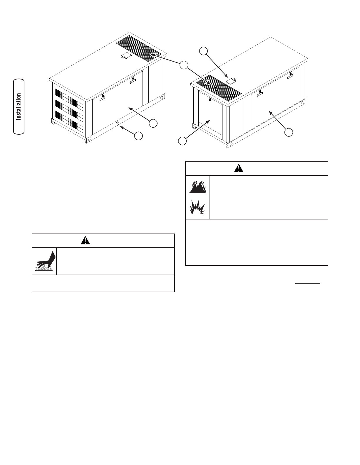
Access Doors
The home generator is equipped with an enclosure that has
three access doors, as shown above. The doors are named
for a significant component located behind them, as follows:
A Fuel Inlet port (shown for reference)
B Control Panel door
C Exhaust opening (shown for reference)
D Coolant Fill door
E Battery door
F Exhaust door (shown for reference)
WARNING
Contact with muffler area can result in serious
burns.
DO NOT touch hot parts and AVOID hot exhaust gases.
•
Allow equipment to cool before touching.
•
The Coolant Fill, Battery and Control Panel doors must be
installed whenever the unit is running.
Each home generator is equipped with two identical keys.
These keys fit the locks that secure the access doors.
To Open an Access Door:
1. Insert key into lock of access door handle you wish
to open and turn one quarter turn counterclockwise.
Remove key. Handle will remain unlocked until you relock it.
2. Grasp door’s handle and turn one quarter turn
counterclockwise to open.
3. Coolant Fill door is unlocked in the same manner. It can
be used for adding coolant or oil.
The Gaseous Fuel System
WARNING
Propane and Natural Gas are extremely
flammable and explosive.
Fire or explosion can cause severe burns or
death.
LP gas is heavier than air and will settle in low areas.
•
Natural gas is lighter than air and will collect in high
•
areas.
The slightest spark can ignite these fuels and cause an
•
explosion.
DO NOT light a cigarette or smoke.
•
The information provided below is to assist gaseous fuel
system technicians in planning installations. In no way
should this information be interpreted to conflict with
applicable fuel gas codes. Consult with your local fuel
supplier or Fire Marshall if questions or problems arise.
TO THE INSTALLER: Consult with the home generator
owner(s) and convey any technical considerations that might
affect their installation plans before applying these general
guidelines.
The following general rules apply to gaseous fuel system
piping:
• The piping should be of a material that conforms to
federal and local codes, rigidly mounted and protected
against vibration.
• Piping should be protected from physical damage
where it passes through flower beds, shrub beds, and
other cultivated areas where damage could occur.
To Close an Access Door:
1. Close door and turn handle one quarter turn clockwise.
2. Insert key into lock in handle and turn one quarter turn
clockwise. Remove key.
10 BRIGGSandSTRATTON.COM
Page 11
• Install the flexible, gaseous hose (supplied) between
the home generator Fuel Inlet port and rigid piping to
prevent thermal expansion or contraction from causing
excessive stress on the piping material.
NOTE: Where local conditions include earthquake, tornado,
unstable ground, or flood hazards, special consideration
shall be given to increase strength and flexibility of piping
supports and connections.
CAUTION
The supplied flexible gaseous pipe is not to be installed
underground or in contact with the ground.
The entire flexible gaseous pipe must be visible for
•
periodic inspection and must not be concealed within,
contact, or run through any wall, floor, or partition.
• Piping must be of the correct size to maintain the
required supply pressures and volume flow under
varying generator load conditions with all gas
appliances connected to the fuel system turned on and
operating.
• Use a pipe sealant or joint compound approved for
use with NG/LPG on all threaded fittings to reduce the
possibility of leakage.
• Installed piping must be properly purged and leak
tested, in accordance with applicable codes and
standards.
WARNING
• Natural gas fuel supply pressure at the generator’s fuel
inlet port should be between 7 to 11 inches of water
(in. W.C.) at full load with all gas appliances turned on
and operating.
The home generator unit has been factory set to run on
natural gas. The unit can be converted from natural gas to
LP gas or vice versa using two people and special tools. See
Fuel Conversion, later in this manual.
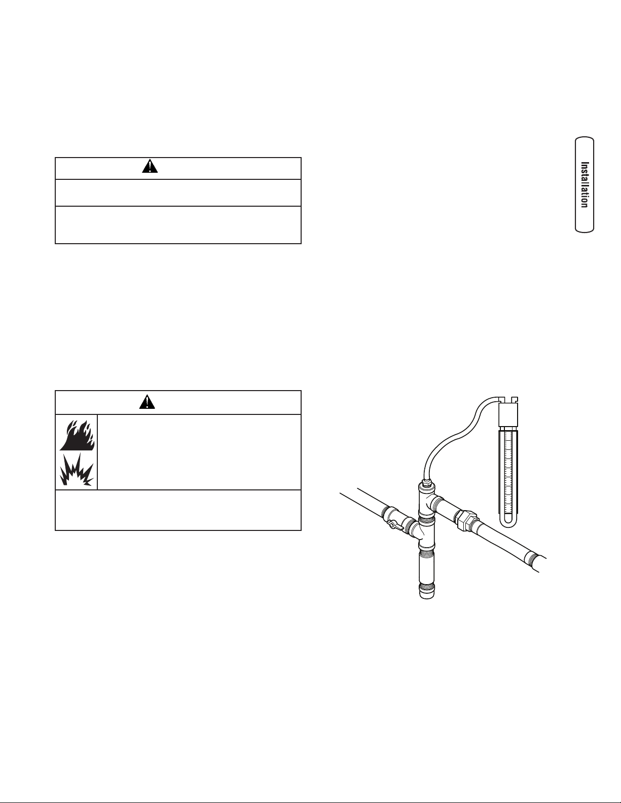
It is recommended that the fuel connection incorporate the
following components:
• A minimum 10 ft. (3 m) section of gas pipe between
the primary fuel regulator and the generator fuel inlet
connection (acts as accumulator for high block loads).
• A manual fuel shut-off valve located in the interior of
the building.
• A manual fuel shut-off valve located outside the
building, just before the generator unit.
• Where the formation of hydrates or ice is known to
occur, piping should be protected against freezing. The
termination of hard piping should include a sediment
trap where condensate is not likely to freeze.
• A manometer port should be provided.
The manometer port permits temporary installation of a
manometer to ensure that the engine receives the correct
fuel pressure to operate efficiently throughout its operating
range.
Propane and Natural Gas are extremely
flammable and explosive.
Fire or explosion can cause severe burns or
death.
Before placing the home generator into service, the fuel
•
system lines must be properly purged and leak tested.
NO leakage is permitted.
•
Consider the following factors when planning to install the
fuel supply system:
• A minimum of one accessible, approved manual shutoff
valve shall be installed in the fuel supply line within
6 ft (1.8 m) of the home generator. A union or flanged
connection shall be provided downstream from this
valve to permit removal of controls.
• LP gas fuel supply pressure should be 7 to 11 inches
of water (in. W.C.) at full load with all gas appliances
turned on and operating.
NOTE: A digital manometer, P/N 19495, is available at your
Briggs & Stratton service center.
11
Page 12
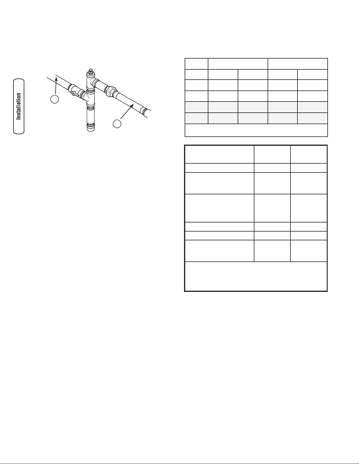
When the initial test runs are completed, the manometer
is removed and the port is plugged. A typical final fuel
connection assembly is shown here, where (A) is the fuel
supply and (B) goes to the home generator.
Fuel Consumption
Estimated fuel supply requirements at half and full load for
natural gas and LP vapor fuels are shown below.
Natural Gas LP Vapor
1/2 Load Full Load 1/2 Load Full Load
27kW 259 C 420 C N/A N/A
A
B
Fuel Pipe Sizing
There are numerous on-line or otherwise-published
references for fuel pipe sizing. The installer should consider
the specific gravity of gas and compensate for a nominal
amount of restriction from bends, fittings, etc. If an unusual
number of fittings, bends, or other restrictions are used,
please refer to federal and local codes.
259,000 B 420,000 B N/A N/A
30kW N/A N/A 92 C 150 C
N/A N/A 228,800 B 373,000 B
C = Cubic feet per hour
B = BTU’s per hour
Physical Properties LP Vapor Natural
Gas
Normal Atmospheric State Gas Gas
Boiling Point (in °F):
Initial
End
Heating Value:
BTU per gallon (Net LHV*)
BTU per gallon (gross**)
Cubic feet (gas)
Density*** 36.39 57.75
Weight† 4.24 2.65
Octane Number:
Research
Motor
* LHV (Low Heat Value) is the more realistic rating.
** Gross heat value does not consider heat lost in the form of water
during combustion.
*** Density is given in “Cubic Feet of Gas per Gallon of Liquid”.
† Weight is given in “Pounds per Gallon of Liquid”.
-44
-44
83,340
91,547
2,500
110+
97
-259
-259
63,310
1,000
110+
12 BRIGGSandSTRATTON.COM
Page 13
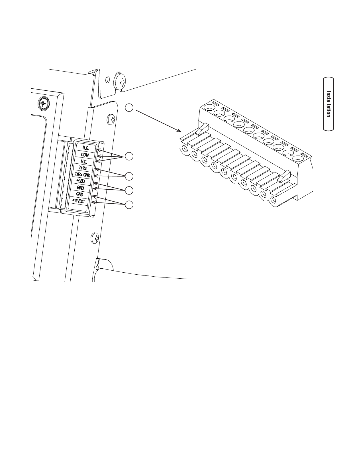
System Connectors
LV connections to signal fault contacts, transfer switch communication, remote LED and auxiliary 12VDC power are made to
a removable ten-pin connector plug. Compare this illustration with your generator to familiarize yourself with the location of
these important connections:
A
B
C
D
E
A - 10 Pole Connector Plug
B - Fault Contacts — Use NO, COM and NC for operating a
siren, light, optional GenAlert, etc. to alert you in case
of a fault. Contacts reverse state (NO goes to NC and
vice versa) upon a fault condition.
C - Transfer Switch Communication — Connect to transfer
switch control board for communication interface.
D - Remote LED Output — Used to connect to the remote
LED supplied with the generator. The remote LED will
turn on and off in a series of blinks if certain faults are
detected in the generator.
E - +12 Volt DC, .5 Amp Output — Internal auxiliary power
supply.
13
Page 14
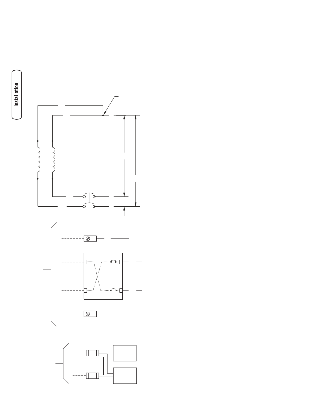
Generator AC Connection System
10 A
10 A
240 VAC
T2
120 V
120 V
240 V
T4
T1
T3
N
G
T4
T1
A single-phase, three-wire AC connection system is used in
the home generator. The stator assembly consists of a pair
of stationary windings with two leads brought out of each
winding. The junction of leads T2 and T3 forms the neutral
lead, as shown schematically and as wiring diagram below. A
complete schematic and wiring diagram can be found later in
this manual.
NOTE: Neutral is not bonded to ground at generator.
Grounding the Generator
Ground the home generator per applicable codes, standards
and regulations. There are two generator GND lug locations.
The one inside the alternator junction box next to the
circuit breaker is the primary lug and should meet most
applications. The second generator GND lug is located on the
frame below the generator circuit breaker cover, and should
ONLY be used for a ground rod located at the generator, if
required by local codes. See Controls for location.
Power Winding
Neutral
Neutral
Neutral
Utility Circuit Connection
“240V Utility” leads must be routed in conduit. The
“240V Utility” leads deliver power to the generator’s circuit
board and water heater. This power also charges the battery.
When power on these leads is lost, the generator will start.
Using installer-supplied minimum 300V, 14 AWG copper
wire, connect each ten-amp fuse terminal in the alternator
junction box to the ten-amp fuse terminals in the automatic
transfer switch.
Fault Detection System
The generator may have to run for long periods of time with
no operator present. For that reason, the system is equipped
with sensors that automatically shut down the generator in
the event of potentially damaging conditions, such as low
oil pressure, high water temperature, over speed, and other
conditions. Refer to Fault Detection System in the Operator’s
Manual for more detailed information.
The owner will use the remote LED indicator to observe the
status of the home generator system. Consult with the owner
for a convenient location. Locate the electrical box in an
area visible by the home owner such as near a garage door
opener or security control panel.
To Transfer Switch
Line 1
To install the remote LED indicator:
1. Push the LED through the mounting plate from the
front until it snaps in place.
Circuit
Breaker
Line 2
IMPORTANT: The LED is polarity sensitive.
2. Using provided 10 pole connector and installer-supplied
minimum 18AWG wire, connect the remote LED to the
generator control board +LED and GND connection.
Use wire nuts to attach wire to LED leads.
Ground
Ground
3. Attach mounting plate to installer-supplied electrical
box.
To Transfer Switch
Connection
Utility Fuse
14 BRIGGSandSTRATTON.COM
Control
Board
Water
Heater
Page 15
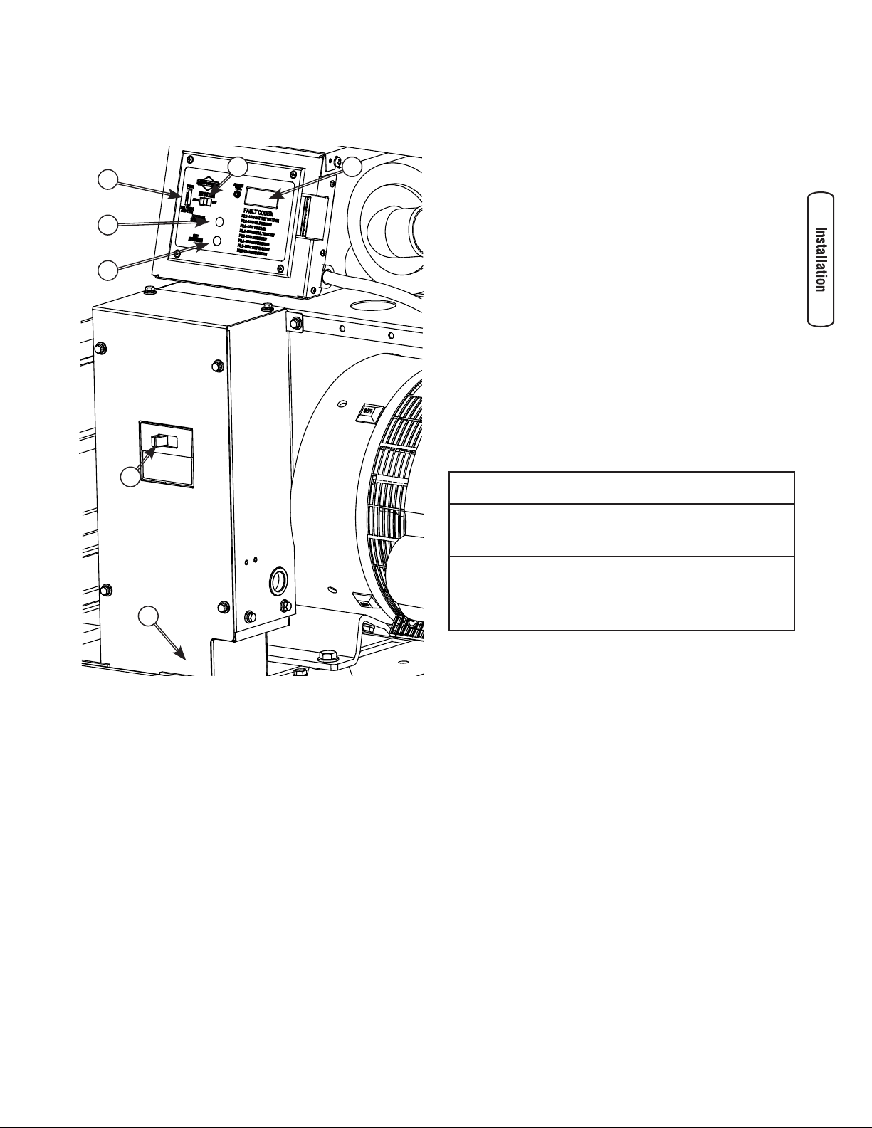
System Control Panel
The home generator control panel, located inside the
generator housing, is shown below.
E
F
D
C
G
System Switch
This two-position switch is the most important control on
the home generator and is used as follows:
• “AUTO” position is the normal operating position. If
a utility power outage is sensed, the system will start
the generator. When utility power is restored, lets the
engine stabilize internal temperatures, shuts off the
generator, and waits for the next utility power outage.
• “OFF” position turns off running generator, prevents
unit from starting and resets any detected faults.
15 Amp Fuse
Protects the home generator DC control circuits. If the fuse
has ‘blown’ (melted open) or was removed, the engine
cannot crank or start. Replace the fuse using only an
identical ATO 15A fuse. One spare fuse is supplied with the
unit. If fuse was blown or removed, you will need to reset
the exercise timer (see Setting Exercise Timer).
Final Installation Considerations
Engine Oil
B
A
Brief descriptions of the controls used during installation are:
A Removable Panel — To assist with conduit connection.
B Circuit Breaker — Must be ON to supply power to the
transfer switch.
C Set Exercise Switch — Used to set time of the exercise
cycle.
D Manual Over-Ride Switch — Used to manually start
and stop the generator.
E 15 Amp Fuse — Protects the DC control circuits.
F System Switch — Switches modes to OFF and AUTO.
G Digital Display — Displays running time in hours, and
fault codes.
More information may be found in Controls in the Operator’s
Manual.
NOTICE
Any attempt to crank or start the engine before it has been
properly serviced with the recommended oil will result in
equipment failure.
Refer to Maintenance and engine manual for oil fill
•
information.
Damage to equipment resulting from failure to follow this
•
instruction will void engine and generator warranty.
This engine is shipped from the factory pre-run and filled
with non-synthetic oil (API SL 10W-30W). This allows for
system operation in a wide range of temperature and climate
conditions. Before starting the engine, check oil level and
ensure that engine is serviced as described in the engine
operator’s manual.
Coolant System
This engine is shipped from the factory filled with a 5050 mix of automotive (Dex-Cool™ orange) anti-freeze and
water. This will provide optimum year round protection
against freezing, boiling and corrosion. The coolant system
incorporates a water heater that operates when ambient
temperature is below 80ºF AND utility power is present at
the transfer switch. Before starting the engine, check coolant
level as described in the engine operator’s manual.
15
Page 16
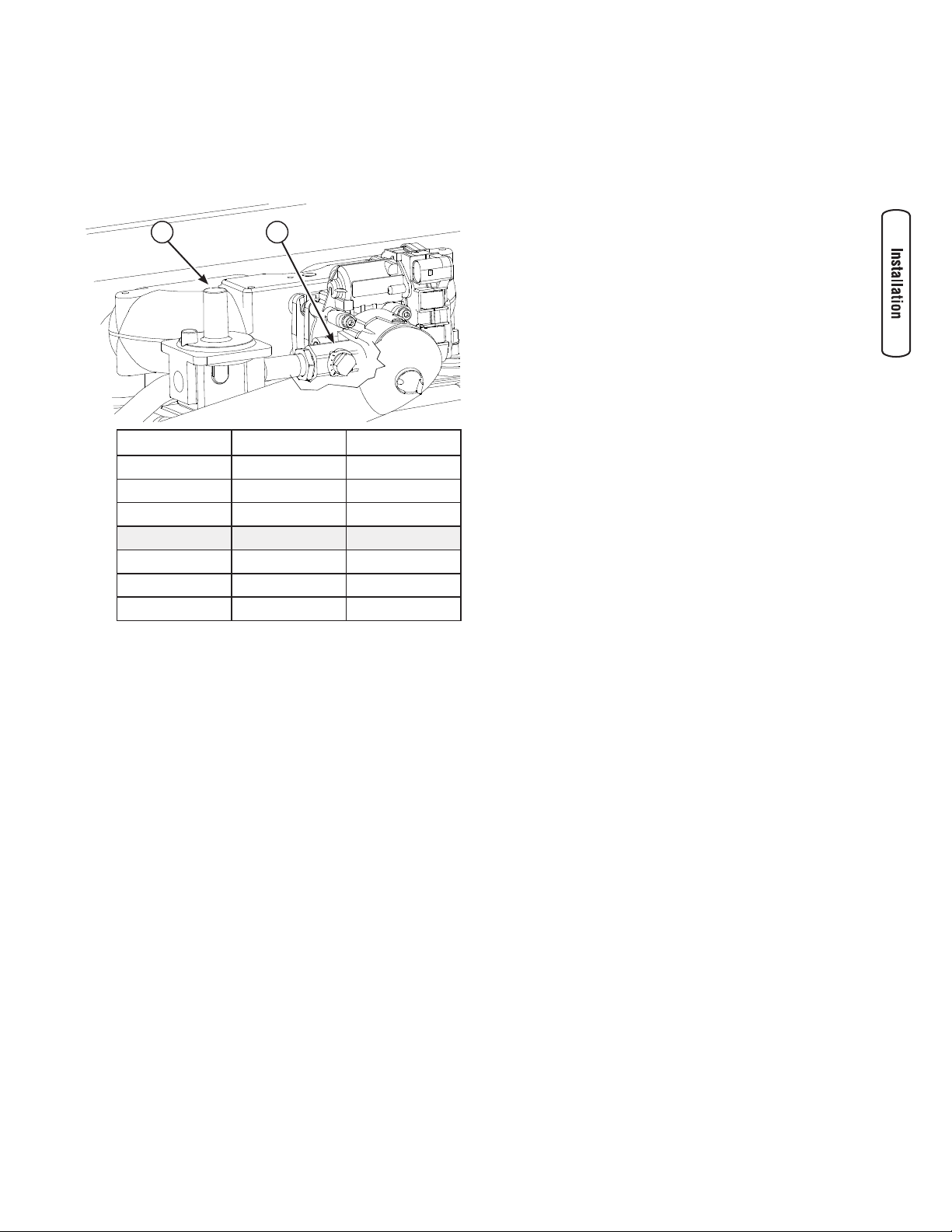
Battery
UNDER-FREQ.
ADJUST
STABILITY
ADJUST
VOLTAGE
ADJUST
The installer must supply a sealed, rechargeable 12 Volt DC,
650 Cold Cranking Amps (CCA) 55 amp hour starting
battery. The battery may not be at full charge when installed.
If battery voltage is below 12 Volts, charge the battery. See
Battery in Maintenance for details.
NOTE: DO NOT use a deep-cycle type battery.
Fuel Supply System
Ensure that all fuel pipe connections are tight, secure and
without leaks.
Ensure that all gas line shutoff valves are OPEN and that
adequate fuel pressure is available whenever automatic
operation is desired.
Initial Start-up (No Load)
Before operating the home generator or placing it into
service, inspect the entire installation carefully.
Then begin testing the system without any electrical loads
connected, as follows:
NOTE: Unit has been set-up for natural gas operation at the
factory. Fuel conversion, if needed, must be completed prior
to performing these steps.
1. Set generator’s main circuit breaker to its ON (closed)
position.
2. Confirm 15 Amp fuse is installed in control panel.
3. Set generator’s system switch to AUTO.
4. Push MANUAL OVER-RIDE button on control panel.
NOTE: When the generator is started for the very first time, it
will require that air in the gaseous fuel lines be purged. This
may take a few minutes.
5. DO NOT crank engine for more than 15 seconds, then
pause for 15 seconds to reduce heat in the starter.
6. Repeat process until engine starts.
7. Listen for unusual noises, vibration or other indications
of abnormal operation. Check for oil or coolant leaks
while engine runs.
8. Let engine warm up for about five minutes to allow
internal temperatures to stabilize.
9. Connect an accurate AC voltmeter and a frequency
meter to check generator output at load side of circuit
breaker. No-load voltage should be 239-244 Volts,
frequency should be 59.8 - 60.2 Hz.
NOTE: If AC voltage is outside these ranges, perform the
generator adjustment, Steps 13 and 14 below.
10. Check generator output between one of the generator
connection lugs and the neutral lug, then between the
other generator connection lug and the neutral lug.
In both cases, voltage reading should be between
117-123 Volts.
11. Push and hold MANUAL OVER-RIDE button on control
panel again until engine stops.
IMPORTANT: DO NOT proceed until you are certain that
generator AC voltage is correct and within the stated limits.
Generator frequency is fixed and not adjustable
12. If voltage and frequency values are correct, proceed to
step 15.
13. Connect voltmeter as described in step 9 above.
14. While observing voltmeter, adjust alternator voltage
control (A) for 240 volts. DO NOT adjust either of the
other alternator controls.
A
15. Install alternator circuit breaker enclosure cover.
16. Close all enclosure access doors.
Fuel Conversion
The unit is shipped from the factory calibrated for NG
operation. To convert the engine from NG to LP vapor
operation, follow these steps:
1. Disconnect NEGATIVE battery cable from battery.
2. Set the generator’s main circuit breaker OFF.
3. Set the control panel System switch to OFF.
4. Install O2 sensor into exhaust manifold.
NOTE: Avoid leaving O2 sensor attached for lengthy period.
5. After purging fuel supply line, push MANUAL OVER-
RIDE button on control panel. When the engine starts,
allow it to warm up for a few minutes under no load.
6. Attach a timing light to engine. Loosen distributor
hold-down clamp. While one person observes timing
indicator, a second person adjusts distributor for
20º before top dead center. Tighten distributor holddown.
NOTE: If converting from LP to NG, use 32º before top dead
center.
16 BRIGGSandSTRATTON.COM
Page 17
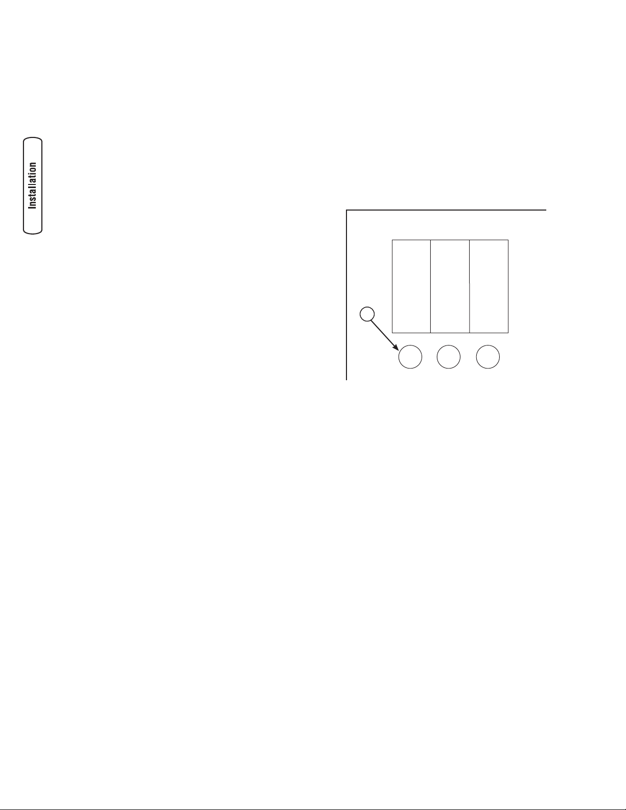
7. While observing O2 Analyzer readout, adjust zero
pressure regulator [ZPR] (A) and main adjustment
screw [MAS] (B) to obtain stoichiometric value shown
in table below. Select table value that corresponds to
your O2 measurement system. Shaded table line is
target value.
A B
Voltage Phi Lamda
2.40 1.000 1.000
2.45 1.012 0.988
2.50 1.024 0.977
2.55 1.036 0.966
2.60 1.048 0.955
2.65 1.060 0.944
2.70 1.071 0.933
11. Set generator’s main circuit breaker ON (resume full
load). Reverify sensor value remains in target area.
Adjust MAS (B) as necessary.
12. Set generator’s main circuit breaker OFF (no load).
Reverify sensor value remains in target area. Adjust
ZPR (A) as necessary.
13. Set the generator’s main circuit breaker OFF.
14. Push and hold the MANUAL OVER-RIDE button on
control panel. When the engine stops, allow it to cool
for a few minutes before proceeding.
15. Remove O2 sensor from exhaust manifold and reinstall
plug. Disconnect timing light from engine.
16. Complete emissions statement and send with
installation checklist.
8. Set generator’s main circuit breaker ON.
9. Apply full load to generator. Adjust MAS (B) to achieve
target value. Clockwise rotation of MAS will cause airfuel mixture to become more lean.
10. Set generator’s main circuit breaker OFF (no load).
Adjust ZPR (A) to achieve target value. Clockwise
rotation of ZPR will cause mixture to become more
rich. Make sure ZPR tower cap is reinstalled prior to
final reading.
17
Page 18
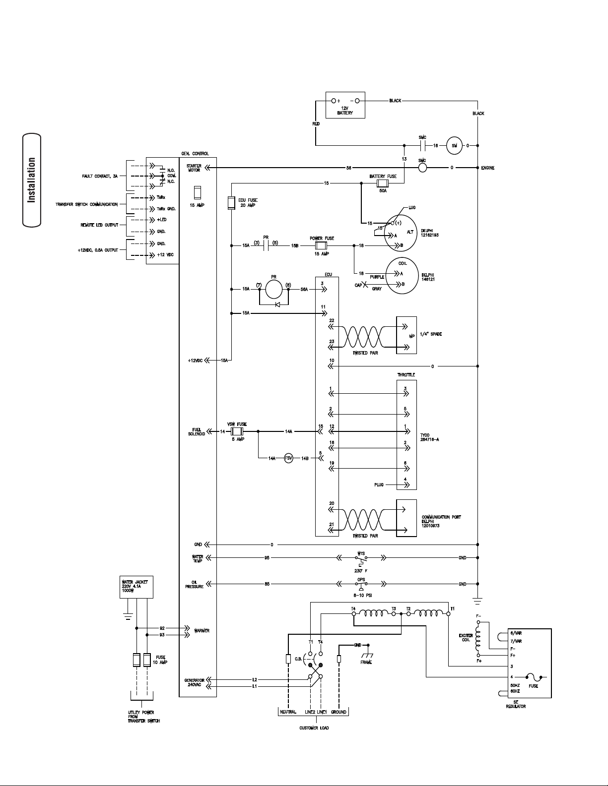
Schematic/ Wiring Diagram
18 BRIGGSandSTRATTON.COM
Page 19

Controls
See the Operator’s Manual for complete description of the
home generator controls.
Operation
Automatic Operation Sequence
The generator’s control panel houses a logic control circuit
board. This control board constantly monitors utility power
source voltage. Should that voltage drop below a preset
level, control board action will signal the engine to crank and
start.
When utility source voltage is restored above a preset
voltage level, the engine is signaled to shut down.
The actual system operation is not adjustable and is
sequenced by sensors and timers on the control board, as
follows:
Utility Voltage Dropout Sensor
• This sensor monitors utility source voltage.
• If utility source voltage drops below about 70 percent
of the nominal supply voltage, the sensor energizes a
10 second timer. The timer is used to ‘sense’ brownouts.
• Once the timer has expired, the engine will crank and
start.
Utility Voltage Pickup Sensor
This sensor monitors utility power supply voltage. When that
voltage is restored above 80 percent of the nominal source
voltage, a time delay starts timing and the engine will go to
engine cool-down.
Engine Cool-down Timer
• When the load is transferred back to the utility power
source, the engine cool-down timer starts timing.
• The timer will run for about one minute, then the
generator will stop.
• Minimum engine run time is 5 minutes.
A button on the control panel is labeled “Set Exercise” (see
System Control Panel). The specific day and the specific
time of day this button is pressed is programmed into the
control board memory. This date and time is then used to
automatically initiate the system exercise cycle. The “SET
EXERCISE” legend on the control panel will flash until the set
exercise cycle is set.
To perform the Set Exercise procedure:
1. Choose the day and time you want your home
generator to exercise.
2. On that day and time, press and hold down the “Set
Exercise” button for three seconds.
NOTE: “SET EXERCISE” will flash until the button is pressed
for three seconds, then “SET EXERCISE” will illuminate for
5 seconds, and finally turn off.
3. The unit will then start and run it’s 20 minute exercise
cycle.
For example, if you press the “Set Exercise” button on
Sunday morning at 10:00 AM, the unit will run an immediate
exercise cycle and an exercise cycle every following Sunday
at 10:00 AM (+/- 1/2 hour).
NOTE: “Set Exercise” will only work if the unit is in the
Automatic mode and this exact procedure is followed.
The exerciser will need to be re-set if the 15 Amp fuse
is removed or changed, or if the 12 Volt DC battery is
disconnected.
If you want to change the day and time the unit exercises,
simply perform the “Set Exercise” procedure at the exact
weekday and time you want it to take place.
Installation Inspection
Complete the ”Installation Checklist” as you make the
inspection. Ensure all items have been filled-in and all
signatures have been obtained. Mail the white copy (and
emissions statement, if completed) to:
Briggs & Stratton Power Products
Warranty Registration
P. O. Box 239
Jefferson, WI 53549-0239
Setting Exercise Timer
The home generator is equipped with an exercise timer that
will start and exercise the system once every seven days.
During this exercise period, the unit runs for approximately
20 minutes and then shuts down. Electrical load transfer
DOES NOT occur during the exercise cycle (unless an utility
power outage occurs).
More detailed Operating, Maintenance and Troubleshooting
information is given in the Operator’s Manual.
19
Page 20

20 BRIGGSandSTRATTON.COM
Page 21

Manual de Instalación y Arranque
Sistema generador
doméstico enfriado por
líquido Serie 30000
Page 22

Muchas gracias por comprar este generador Briggs & Stratton de gran calidad. Nos alegra que haya depositado su confianza
en la marca Briggs & Stratton. Siempre que sea conforme a las instrucciones del manual del operario, su generador Briggs &
Stratton le proporcionará muchos años de buen funcionamiento.
Este manual contiene información sobre seguridad para hacerle consciente de los riesgos asociados a los generadores
y mostrarle cómo evitarlos. Este generador se ha diseñado exclusivamente para suministrar energía eléctrica a cargas
compatibles de iluminación, electrodomésticos, herramientas y motores. No debe utilizarse para ningún otro fin. Es
importante leer detenidamente y comprender estas instrucciones antes de poner en marcha o utilizar el equipo. Este producto
no pertenece a la categoría de reserva de emergencia según lo definido por la norma NFPA 70 (NEC).
Antes de utilizar el generador doméstico de reserva, es necesario que lo instale un profesional. El manual de instalación
ofrece información completa. Siga todas las instrucciones. Conserve este manual para futuras consultas.
Dónde encontrarnos
Nunca tendrá que buscar mucho para poder obtener soporte y servicio técnico para su equipo generador de reserva. Consulte
las páginas amarillas. Existen miles de distribuidores de servicio autorizados de Briggs & Stratton en todo el mundo. También
puede dirigirse al departamento de servicio al cliente de Briggs & Stratton llamando al (800) 743-4115 o utilizar el buscador
de centros de servicio técnico de BRIGGSandSTRATTON.COM, que ofrece la lista de los distribuidores de servicio autorizados
de Briggs & Stratton.
Fecha de compra
Generador
Número de Modelo
Revisión
Número de Serie
Motor
Número de Modelo
Número de Serie
Briggs & Stratton Power Products Group, LLC.
900 North Parkway
Jefferson, WI 53549
Copyright © 2008 Briggs & Stratton Power Products Group, LLC.
Reservados todos los derechos. Queda prohibida la reproducción
o transmisión total o parcial de este material, sea cual sea la
forma y el medio empleados para ello, sin el permiso previo y por
escrito de Briggs & Stratton Power Products Group, LLC.
Page 23

Tabla de contenido
Instrucciones importantes de seguridad . . . . . . . . . . . . . . . . 4
Instalación . . . . . . . . . . . . . . . . . . . . . . . . . . . . . . . . . . . . 7
Responsabilidades del instalador. . . . . . . . . . . . . . . . . . . . . . . . . . . . . . . . . 7
Inspección al Momento de la Entrega . . . . . . . . . . . . . . . . . . . . . . . . . . . . . 7
Contenido de la Caja . . . . . . . . . . . . . . . . . . . . . . . . . . . . . . . . . . . . . . . . . .7
Ubicación del Sistema de Generador de Doméstico . . . . . . . . . . . . . . . . . .8
Puertas de Acceso . . . . . . . . . . . . . . . . . . . . . . . . . . . . . . . . . . . . . . . . . . . 10
Sistema de combustible gaseoso. . . . . . . . . . . . . . . . . . . . . . . . . . . . . . . . 11
Consumo de Combustible . . . . . . . . . . . . . . . . . . . . . . . . . . . . . . . . . . . . . 12
Conexiones de Sistema . . . . . . . . . . . . . . . . . . . . . . . . . . . . . . . . . . . . . . . 13
Conexión a Tierra del Generador . . . . . . . . . . . . . . . . . . . . . . . . . . . . . . . . 14
Interconexiones del Circuito de Control. . . . . . . . . . . . . . . . . . . . . . . . . . . 14
Panel de Control del Sistema. . . . . . . . . . . . . . . . . . . . . . . . . . . . . . . . . . . 15
Consideraciones finales para la instalación . . . . . . . . . . . . . . . . . . . . . . . . 15
Sistema de Suministro de Combustible. . . . . . . . . . . . . . . . . . . . . . . . . . . 16
Arranque inicial (sin carga) . . . . . . . . . . . . . . . . . . . . . . . . . . . . . . . . . . . . 16
Conversión de combustible . . . . . . . . . . . . . . . . . . . . . . . . . . . . . . . . . . . . 17
Mandos . . . . . . . . . . . . . . . . . . . . . . . . . . . . . . . . . . . . . 18
Utilización. . . . . . . . . . . . . . . . . . . . . . . . . . . . . . . . . . . . 18
Secuencia de operación automática. . . . . . . . . . . . . . . . . . . . . . . . . . . . . . 18
Configuración del temporizador de práctica. . . . . . . . . . . . . . . . . . . . . . . . 19
Inspección posterior a la instalación . . . . . . . . . . . . . . . . . . . . . . . . . . . . . 19
Español
3
Page 24

Conserve estas instrucciones
Instrucciones importantes de
seguridad
El símbolo de alerta de seguridad ( ) es usado con una
palabra (PELIGRO, ADVERTENCIA, PRECAUCIÓN), un
mensaje por escrito o una ilustración, para alertarlo acerca
de cualquier situación de peligro que pueda existir. PELIGRO
indica un riesgo el cual, si no se evita, causará la muerte o
una herida grave. ADVERTENCIA indica un riesgo el cual, si
no se evita, puede causar la muerte o una herida grave.
PRECAUCIÓN indica un riesgo, el cual, si no se evita, puede
causar heridas menores o moderadas. AVISO indica una
situación que podría resultar en el daño del equipo. Siga los
mensajes de seguridad para evitar o reducir los riesgos de
heridas e inclusive la muerte.
Este manual contiene instrucciones de instalación, puesta
en marcha y ajuste de un sistema generador doméstico
que suministra energía eléctrica a dispositivos monofásicos
de 120/240 V y 60 Hz. El sistema generador doméstico se
puede utilizar con propano líquido (LP) o gas natural como
combustible. Los manuales del operario de la máquina
y del generador se entregan por separado y contienen
instrucciones de operación y mantenimiento para este
sistema.
Se han tomado todos los recaudos posibles para asegurar
que la información incluida en este manual sea correcta y
esté actualizada. Sin embargo, los fabricantes se reservan el
derecho de cambiar, alterar o mejorar el sistema de cualquier
otra manera y en cualquier momento, sin previo aviso.
Símbolos de Peligro y Significados
Explosión
Gases Tóxicos
Fuego
Partes en Movimiento Superficie Caliente
Descarga Eléctrica
ADVERTENCIA
Las baterías almacenadas producen hidrógeno
explosivo mientras estén siendo recargadas.
Una pequeña chispa puede encender el
hidrógeno y causar una explosión.
El fluido de electrolito de la batería contiene
ácido y es extremadamente cáustico.
El contacto con el fluido de la batería puede
causar quemaduras químicas severas.
Las baterías presentan un riesgo de
descarga eléctrica y de elevada corriente de
cortocircuito.
NO deseche la batería tirándola al fuego.
•
No permita ninguna llama abierta, chispa, calor, o
•
encienda un cigarrillo durante y por varios minutos
después de haber recargado la batería.
NO abra ni manipule la batería.
•
Lleve puestos las gafas protectoras, delantal y guantes
•
de goma.
No lleve relojes, anillos ni otros objetos metálicos.
•
Utilice herramientas con mangos aislados.
•
ADVERTENCIA
Al motor funcionar, se produce monóxido de
carbono, un gas inodoro y venenoso.
Respirar monóxido de carbono puede provocar
dolor de cabeza, fatiga, mareos, vómitos,
confusión, ataques, náuseas, desmayos o
incluso la muerte.
Opere el generador SOLAMENTE al aire libre.
•
Instale una alarma de monóxido de carbono con batería
•
cerca de los dormitorios.
Asegúrese de que los gases de escape no puedan entrar
•
por ventanas, puertas, tomas de aire de ventilación u
otras aberturas en un espacio cerrado en el que puedan
acumularse.
ADVERTENCIA
El escape del motor de este producto contiene
elementos químicos reconocidos en el Estado de
Presión ExplosivaArranque automático
Peligro al elevar Manual del Operario
4 BRIGGSandSTRATTON.COM
Quemaduras Química
California por producir cáncer, defectos de nacimiento
u otros daños de tipo reproductivo.
Page 25

ADVERTENCIA
Los generadores producen un voltaje muy
poderoso.
Si no hace tierra apropiadamente con un
generador, puede hacer que ocurra un
electrocutamiento.
Si no aísla el generador de utilidades de
energía, puede hacer que los trabajadores de
electricidad sufran heridas graves e inclusive
la muerte, debido a la retroalimentación de la
energía eléctrica.
Cuando use un generador como poder de energía
•
auxiliar, notifique a la compañía de utilidades.
NO toque los alambres pelados o receptáculos.
•
NO maneje el generador o cables eléctricos mientras esté
•
parado en agua, descalzo o cuando las manos y los pies
estén mojados.
Si fuera necesario realizar trabajos en cercanías de la
•
unidad mientras está en funcionamiento, párese sobre
una superficie seca y aislada para reducir los riesgos de
una descarga.
NO permita que personas descalificadas o niños operen
•
o sirvan al generador.
En caso de que se produzca un accidente causado por
•
una descarga eléctrica, cierre inmediatamente la fuente
de energía eléctrica y contacta administración local. Evite
el contacto directo con la víctima.
A pesar del diseño seguro del sistema de generador de
•
doméstico, si se opera este equipo en forma imprudente,
si no se cumple con el mantenimiento o si se actúa con
descuido, se pueden producir lesiones o la muerte.
Permanezca siempre alerta cuando trabaje con este
•
equipo. NUNCA trabaje con este equipo si se siente
cansado física o mentalmente.
Antes de realizar cualquier tarea de mantenimiento en
•
el generador, desconecte primero el cable de la batería
marcado como NEGATIVE, NEG o (-). Cuando haya
terminado, vuelva a conectar el cable en último lugar.
Una vez que el sistema de generador de doméstico está
•
instalado, el generador puede arrancar manualmente sin
ninguna advertencia cada vez que se produce una falla
en el suministro de electricidad. Para evitar posibles
lesiones, siempre fije el conmutador del sistema en OFF,
Y retire el fusible de 15 Amperios ANTES de realizar
trabajos en el equipo.
ADVERTENCIA
El Gas Natural y el Propano son
extremadamente inflamables y explosivos.
El fuego o una explosión pueden causar
quemaduras severas e inclusive la muerte.
Instale el sistema de suministro de combustible de
•
acuerdo con los códigos de gas combustible que
correspondan.
Antes de poner en servicio el sistema de generador de
•
doméstico, se deben purgar las líneas del sistema de
combustible y se debe probar si presentan pérdidas.
Una vez instalado el sistema, se lo debe inspeccionar en
•
forma periódica.
NO se debe permitir que se produzca ninguna pérdida.
•
NO haga funcionar el motor si se percibe olor a
•
combustible o si existe alguna otra fuente de ignición.
NO fume cerca del generador. Limpie en forma inmediata
•
cualquier derrame de aceite. Asegúrese de no dejar
materiales combustibles en el compartimiento del
generador. Mantenga el área próxima al generador limpia
y libre de desperdicios.
ADVERTENCIA
Tensión peligrosa
El contacto con los cables eléctricos puede
provocar electrocución y quemaduras.
Peligro al elevar el equipo / Objeto pesado
Puede provocar daños en los músculos y en la
espalda.
NO toque ningún cable eléctrico cuando utilice el equipo
•
de elevación/izado requerido.
NO eleve ni mueva el generador sin ayuda.
•
Utilice tubos de elevación o correas como se describe en
•
la sección Elevación del generador. La unidad se puede
mover y provocar lesiones.
NO levante la unidad por la parte superior; podría
•
provocar daños en el generador.
ADVERTENCIA
El arrancador y otras piezas que rotan pueden
enredar las manos, el pelo, la ropa, o los
accesorios.
Español
NUNCA utilice la generador sin sus carcasas o tapas de
•
protección.
NO use ropa suelta, joyas o elementos que puedan que-
•
dar atrapados en el arranque o en otras partes rotatorias.
Ate para arriba el pelo largo y quite la joyería.
•
5
Page 26

ADVERTENCIA
El contacto con la zona del silenciador puede
producir quemaduras graves.
Los gases y el calor de escape pueden inflamar
los materiales combustibles y las estructuras y
provocar un incendio.
NO toque las superficies calientes y evite los gases del
•
escape a alta temperatura.
Permita que el equipo se enfríe antes de tocarlo.
•
NO instale el generador a menos de 1,5 metros (5 pies)
•
de todo material combustible o estructura con muros
combustibles cuya resistencia al fuego sea inferior a una
hora.
Deje un espacio mínimo de 91 cm (3 pies) alrededor del
•
generador, incluida la parte superior.
El Código de Normativa Federal (CFR, Título 36:
•
Parques, Bosques y Propiedad Pública) obliga a instalar
una pantalla apagachispas en los equipos con motor
de combustión interno y a mantenerla en buenas
condiciones de funcionamiento, conforme a la norma
5100-1C (o posterior) del Servicio Forestal de la USDA.
En el Estado de California, la ley exige el uso de una
pantalla apagachispas (Sección 4442 del Código de
Recursos Públicos de California). En otros estados puede
haber leyes similares en vigor.
PRECAUCIÓN
Las velocidades de operación en exceso, aumentan los
riesgos de heridas y daños al generador.
Las velocidades bajan en exceso, imponen una carga muy
pesada.
NO cambie ninguna velocidad determinada. El generador
•
suministra una frecuencia y un voltaje calificado cuando
funciona a una velocidad determinada.
NO modifique al generador en ninguna forma.
•
AVISO
El sobrepasar la capacidad del amperaje y vataje del
generador, puede dañar al generador y los aparatos
eléctricos conectados al mismo.
Vea Circuitos Fundamentales en la manual del operario.
•
Encienda su generador y deje que el motor se estabilice
•
antes de conectar las cargas eléctricas.
AVISO
El tratamiento inadecuado del generador puede dañarlo y
acortar su vida productiva.
Use el generador solamente con la finalidad para el cual
•
fue diseñado.
Si usted tiene alguna pregunta acerca de las finalidades
•
de uso del generador, pregúntele a su concesionario o
contacte a Briggs and Stratton.
Opere el generador solamente en superficies niveladas.
•
Para la correcta operación del generador es fundamental
•
contar con ventilación y una circulación de aire de
refrigeración adecuada y que no sufra obstrucciones.
Las puertas de llenado de refrigerante, de la batería y del
•
panel de control deben estar instaladas siempre que la
unidad esté en funcionamiento.
No exponga al generador a una humedad excesiva, polvo,
•
suciedad o vapores corrosivos.
A pesar del diseño seguro del generador doméstico, si se
•
opera este equipo en forma imprudente, si no se cumple
con el mantenimiento o si se actúa con descuido, se
pueden producir lesiones o la muerte.
Permanezca siempre alerta cuando trabaje con este
•
equipo. NUNCA trabaje con este equipo si se siente
cansado física o mentalmente.
Nunca encienda el motor si el filtro de aire o su cubierta
•
han sido retirados.
No inserte cualquier objeto a través de las ranuras de
•
enfriamiento.
Nunca utilice el generador ni ninguna de sus piezas
•
como escalera. Si se sube sobre la unidad, sus piezas se
pueden ver sobreexigidas y pueden romperse. Esto puede
dar como resultado condiciones de operación peligrosas
como consecuencias de la fuga de gases del escape,
pérdida de combustible, pérdida de aceite, etc.
Si los aparatos conectados se sobrecalientan, apáguelos
•
y desconéctelos del generador.
Apague el generador si:
•
-Se pierde la salida eléctrica;
-El equipo produce chispas, humo o emite llamas;
-La unidad vibra de una manera excesiva.
6 BRIGGSandSTRATTON.COM
Page 27

Instalación
Descripción del equipo
Este producto está pensado para utilizarlo como un sistema
de reserva doméstico opcional que proporciona una fuente
alternativa de energía eléctrica con capacidad para alimentar
cargas tales como sistemas de calefacción y refrigeración y
sistemas de comunicaciones, que cuando dejan de funcionar
a causa de una interrupción de la alimentación eléctrica
de la red pueden producir incomodidades o problemas.
Este producto no pertenece a la categoría de reserva de
emergencia según lo definido por la norma NFPA 70 (NEC).
Responsabilidades del cliente
• Lea y cumpla las instrucciones incluidas en el Manual
del Operario, en especial la sección dedicada a la
seguridad y la sección relacionada con la selección de
los circuitos fundamentales.
• Siga un programa regular para mantener, cuidar y
utilizar el sistema de generador de doméstico, según se
especifica en el Manual del Operario.
Responsabilidades del instalador
• Lea y observe las reglas de seguridad que se
encuentran en el Manual del Operario.
• En la caja encontrará una lista de los conmutadores
de transferencia recomendados aprobados por UL y
que son compatibles con el sistema de generador de
doméstico.
• Lea y siga las instrucciones que se encuentran en este
Manual de Instalación.
IMPORTANTE: El sistema está equipado con un calentador
de agua que se activa cuando la temperatura ambiente es
menor a 26,6 °C (80 °F) Y el conectador recibe alimentación
de la red pública.
Precauciones al Momento del Desempaque
La unidad se envía lista para su instalación en una solera de
cemento reforzada y preparada o en una base diseñada para
tal fin. Tenga cuidado a fin de evitar daños causados por
caídas, golpes, choques, etc. Guarde y desempaque la caja
ubicando el lado correcto hacia arriba, tal como se indica en
la misma.
Inspección al Momento de la Entrega
Luego de retirar la caja, inspeccione cuidadosamente el
sistema de generador de doméstico para detectar cualquier
daño que pudiera haber ocurrido durante el traslado.
IMPORTANTE: Si en el momento de la entrega se detecta
alguna pérdida o daño, solicite a la persona o personas
encargadas de la entrega que dejen debida constancia
en la nota de entrega y que firmen debajo de la nota del
consignador donde se informa acerca de la pérdida o daño.
Si la pérdida o el daño se detecta después de la entrega,
separe los materiales dañados y póngase en contacto
con el transportista para llevar a cabo los procedimientos
de reclamo. Las piezas perdidas o dañadas no están
garantizadas.
Contenido de la Caja
El sistema de generador de doméstico incluye lo
siguiente:
• Generador doméstico.
• Sistema refrigerante con todos los servicios.
• Sistema de aceite/lubricante con todos los servicios.
• Acoplamiento flexible para combustible con
clasificación UL569/CSA8.3.
• Manual de instalación y arranque.
• Manual del operario.
• Manual del operario del motor.
• Lista de control de la instalación.
• Dos llaves para puerta de acceso.
• Un fusible de 15 A de repuesto.
• Conector del panel de control de 10 polos.
• Kit de LED remotos (LED rojo/placa/tornillos).
No incluye:
• Batería de arranque de 650 CCA (NO de ciclo
profundo).
• Cable y conducto de conexión.
• Válvulas/tubería de suministro de combustible.
Herramientas/equipos especiales necesarios
• Dos tramos de 1,52 m (60 pulg.) Programa 40 de tubo
de 5 cm (2 pulg.) (NO conducto).
• Correas, cadenas o cables de elevación
• Perforadores para acero de 7 ga.
• Destornillador de torsión, rango de 5 a 50 pulgadaslibra.
• Luz de temporización de arranque.
• Medidor de mezcla de combustible (sensor y analizador
de O2)
Español
7
Page 28

Ubicación del Sistema de Generador de
Doméstico
Antes de aplicar estas pautas generales, consulte al
propietario y comuníquele cualquier factor técnico a tener en
cuenta que pudiera influir en sus decisiones y deseos.
ADVERTENCIA
Los gases y el calor de escape pueden inflamar
los materiales combustibles y las estructuras
provocar un incendio.
NO instale el generador a menos de 1,5 metros (5 pies)
•
de todo material combustible o estructura con muros
combustibles cuya resistencia al fuego sea inferior a una
hora.
Ubicación del Generador
Sitúe el generador en una zona bien ventilada que permita
la eliminación de los gases de escape mortales. NO instale
el generador en lugares en los que los gases de escape se
puedan acumular o entrar en un edificio que pueda estar
ocupado. Asegúrese de que los gases de escape no puedan
entrar por ventanas, puertas, tomas de aire de ventilación
u otras aberturas en un espacio cerrado en el que puedan
acumularse. Tenga en cuenta los vientos y las corriente de
aire preponderantes cuando elija la ubicación del generador.
aspersores no pueda inundarla, mojar la caja ni
penetrar por las aberturas de entrada o salida de aire.
• Instale la unidad de forma que no dificulte ni afecte
a servicios tales como el teléfono, la electricidad, el
suministro de combustible, el aire acondicionado o el
riego, incluidos los servicios ocultos o subterráneos.
• Instale la unidad en un lugar donde las aberturas de
entrada y salida de aire no queden obstruidas por
hojas, pasto, nieve, etc. Si los vientos preponderantes
ocasionan voladuras o arrastres, es posible que deba
construir un rompevientos para proteger la unidad.
• Instale el generador lo más cerca posible del sistema
de transferencia de energía automático para reducir la
longitud del cableado y las canalizaciones.
• Instale el generador lo más cerca posible del suministro
de combustible para reducir la longitud de los caños.
IMPORTANTE: Es posible que las leyes o los códigos locales
regulen la distancia al suministro de combustible.
A continuación, se muestran los espacios libres mínimos
entre el generador (A) y los materiales combustibles (C) y
(D) desde una perspectiva superior.
5’ (1.5m)
ADVERTENCIA
Al motor funcionar, se produce monóxido de
carbono, un gas inodoro y venenoso.
Respirar monóxido de carbono puede provocar
dolor de cabeza, fatiga, mareos, vómitos,
confusión, ataques, náuseas, desmayos o
incluso la muerte.
Opere el generador SOLAMENTE al aire libre.
•
Instale una alarma de monóxido de carbono con batería
•
cerca de los dormitorios.
Asegúrese de que los gases de escape no puedan entrar
•
por ventanas, puertas, tomas de aire de ventilación u
otras aberturas en un espacio cerrado en el que puedan
acumularse.
Pautas Generales para la Ubicación del Generador
• La unidad SÓLO debe instalarse en exteriores.
• Ubique la unidad en un lugar preparado, que sea plano
y cuente con sistemas de drenaje de agua.
• Instale la unidad en un lugar en el que el agua
procedente de bombas, canalizaciones de desagüe,
canalones de tejado, sistemas de irrigación o
5’ (1.5m) 5’ (1.5m)
C
5’ (1.5m)
D
A Generador de reserva doméstico.
B Escape del motor.
C Material o estructura combustible con una clasificación
de resistencia al fuego de menos de 1 hora.
D Cualquier estructura o material. NO conecte (A) o (D) a
(E).
A
B
D
8 BRIGGSandSTRATTON.COM
Page 29

• Estas distancias se ofrecen para ayudar a ubicar el
49”
14.25”
94”
78”
38”
9.5”
7”
7.38”
34.25”
10.5”
8”
generador teniendo EXCLUSIVAMENTE en cuenta la
presencia de materiales combustibles, la refrigeración
del generador y el mantenimiento.
• Las distancias mínimas son las que se muestran en la
ilustración. Ninguno de los cuatro lados del generador
puede quedar cerrado ni obstruido, aunque se
mantengan las distancias mínimas. NO conecte (C) a (D).
• No se puede utilizar un techo.
• Evite la acumulación de los gases (B) de escape.
Consulte la advertencia sobre monóxido de carbono en
las normas de seguridad.
Solera de concreto
En la ubicación apropiada, construya una solera de cemento
(con una fuerza de compresión de 28 días de 3000 psi
(200 MPa)) con 12,7 cm (5 pulgadas) mínimo de espesor y
15,2 cm (6 pulgadas) más ancha que la caja, en todos sus
lados. Refuerce la solera con barras de refuerzo No. 6 (en
centros de 30,5 cm [12 pulg.]) o tela de alambres de acero
de 8 ga (centros de 15,2 cm [6 pulg.]). Evite colocar refuerzo
en el área del cabo de entrada.
Fije la unidad a la solera con pernos de anclaje de
mampostería de un diámetro de 7,9 mm (5/16 de pulg.)
(mínimo) lo suficientemente largos como para sostener la
unidad.
Ubicación de las entradas eléctricas y de
combustible
De preferencia, utilice un cabo de cable de alimentación que
pase por la solera (ver arriba). Si no se utilizan cabos, (A)
indica la ubicación recomendada donde deberá perforar los
orificios para fijar el conducto de alimentación. El conector
de la entrada de combustible (B) se muestra para fines de
referencia.
A
B
NPT HEMBRA
DE 1”
Orificio de
entrada de
combustible
Base de la
caja
Orificio de
escape (se
muestra
para
fines de
referencia)
Elevación del Generador
El generador pesa más de 773 kg (1.700 libras). Todas las
fases de manipulación y traslado del generador requieren el
uso de herramientas, equipos y profesionales cualificados.
ADVERTENCIA
Tensión peligrosa
Ubicación
del extremo
del cable de
alimentación
NO toque ningún cable eléctrico cuando utilice el equipo
•
de elevación/izado requerido.
NO eleve ni mueva el generador sin ayuda.
•
Utilice tubos de elevación o correas como se describe en
•
la sección Elevación del generador. La unidad se puede
mover y provocar lesiones.
NO levante la unidad por la parte superior; podría
•
provocar daños en el generador.
Vista superior de la solera
El contacto con los cables eléctricos puede
provocar electrocución y quemaduras.
Peligro al elevar el equipo / Objeto pesado
Puede provocar daños en los músculos y en la
espalda.
Español
9
Page 30

Se requieren dos segmentos de 1,5 m (60 pulg.) Programa 40
de tubo de 5 cm (2 pulg.) (B), suministrados por el instalador,
para levantar el generador y colocarlo sobre el soporte
de cemento. Inserte los tubos a través de los orificios de
elevación (A) ubicados cerca de la base de la unidad.
A
B
Utilice una barra separadora para garantizar que las cadenas,
correas o cables NO toquen la parte superior del generador.
Puertas de Acceso
El generador doméstico dispone de una caja con tres puertas
de acceso, como se muestra en la ilustración anterior. La
denominación de las puertas corresponde al componente
principal alojado tras ellas:
A Orificio de Entrada de Combustible (se muestra como
referencia)
B Puerta del Panel de Control
C Orificio de Gases de Escape
D Puerta de Llenado de Aceite
E Puerta de la Batería
F Puerta para Gases de Escape (se muestra como
referencia)
ADVERTENCIA
El contacto con la zona del silenciador puede
producir quemaduras graves.
NO toque las superficies calientes y evite los gases del
•
escape a alta temperatura.
Permita que el equipo se enfríe antes de tocarlo.
•
Las puertas de llenado de refrigerante, de la batería y del
panel de control deben estar instaladas siempre que la
unidad esté en funcionamiento.
Cada generador doméstico está equipado con dos llaves
idénticas que accionan los cerrojos de las puertas de acceso.
Para abrir una puerta de acceso:
1. Inserte la llave en la cerradura del picaporte de la
puerta de acceso que desee abrir y gire un cuarto
de vuelta hacia la izquierda. Retire la llave. El cerrojo
del picaporte se quedará abierto hasta que vuelva a
cerrarlo.
2. Agarre el picaporte de la puerta y gire un cuarto de
vuelta hacia la izquierda para abrir.
3. El cerrojo de la puerta de llenado de refrigerante se
abre del mismo modo. Se puede usar para añadir
refrigerante o aceite.
Para cerrar una puerta de acceso:
1. Cierre la puerta y gire su picaporte un cuarto de vuelta
hacia la derecha.
2. Inserte la llave en la cerradura de la puerta de acceso y
gire un cuarto de vuelta hacia la derecha. Retire la llave.
D
C
B
A
F
10 BRIGGSandSTRATTON.COM
E
Page 31

Sistema de combustible gaseoso
ADVERTENCIA
El Gas Natural y el Propano son
extremadamente inflamables y explosivos.
El fuego o una explosión pueden causar
quemaduras severas e inclusive la muerte.
El gas LP es más pesado que el aire y se puede
•
concentrar en áreas bajas.
El gas natural es más liviano que el aire y se puede
•
concentrar en áreas elevadas.
Hasta la menor chispa puede hacer que estos
•
combustibles se enciendan y causen una explosión.
NO encienda un cigarrillo o fume.
•
La información que se encuentra a continuación sirve
para asistir a los técnicos especializados en sistemas
de combustibles gaseosos en la planificación de las
instalaciones. En ninguna circunstancia esta información
debe interpretarse en forma contraria a los códigos
aplicables a temas de gas combustible. Consulte al
proveedor de combustible local o al supervisor del
departamento de bomberos si surgen problemas o
preguntas.
AL INSTALADOR: Antes de aplicar estas pautas generales,
consulte al propietario del sistema de generador de
doméstico y comuníquele cualquier factor técnico a tener en
cuenta que pudiera influir en sus planes de instalación.
Las siguientes son reglas generales que se aplican a las
cañerías utilizadas en los sistemas de combustible gaseoso:
• Las tuberías deben ser de un material que cumpla los
reglamentos nacionales y locales y deben montarse
rígidamente y protegerse contra las vibraciones.
• Los tubos deben estar protegidos contra daños físicos
cuando pasen por arriates de flores y arbustos y por
otras zonas cultivadas.
• Instale el tubo flexible para gases (suministrado) entre
la entrada de combustible del sistema de generador
de doméstico y los tubos rígidos para evitar que la
expansión o contracción térmica someta a un exceso
de presión a los tubos.
NOTA: En caso de peligro de terremoto, tornado,
inestabilidad del terreno o inundación, se recomienda
adoptar medidas especiales para mejorar la resistencia y
flexibilidad de los soportes y las conexiones de los tubos.
PRECAUCIÓN
• La dimensión de los tubos debe ser la adecuada para
mantener la presión y el caudal suficientes en distintas
condiciones de carga del generador, con todos los
equipos de gas conectados al sistema de combustible y
en funcionamiento.
• Use un sellador de tuberías o compuesto para
uniones aprobado para uso con NG/LPG en todos los
acoplamientos con rosca para reducir la posibilidad de
fugas.
• Las cañerías instaladas deben ser adecuadamente
purgadas y se debe verificar que no tengan
fugas, de acuerdo con las normas y los códigos
correspondientes.
ADVERTENCIA
El Gas Natural y el Propano son
extremadamente inflamables y explosivos.
El fuego o una explosión pueden causar
quemaduras severas e inclusive la muerte.
Antes de poner en servicio el sistema de generador de
•
doméstico, se deben purgar las líneas del sistema de
combustible y se debe probar si presentan pérdidas.
No se debe permitir que se produzca ninguna pérdida.
•
Tenga en cuenta los siguientes factores cuando planifique
la instalación del sistema de suministro de combustible:
• Se debe instalar como mínimo una válvula de paso
manual homologada y accesible en el conducto de
suministro de combustible a menos de 1,8 m (6 pies)
del sistema de generador de doméstico. Se instalará
una unión o conexión con brida entre la válvula y el
equipo para facilitar el desmontaje de los mandos.
• La presión de suministro de LP debe estar entre
7 y 11 pulgadas de columna de agua con carga
completa con todos los aparatos de gas encendidos y
en funcionamiento.
• La presión de suministro de gas natural en la entrada
de combustible del generador debe estar entre
7 y 11 pulgadas de columna de agua con carga
completa con todos los aparatos de gas encendidos y
en funcionamiento.
La unidad de generador doméstico ha sido configurada de
fábrica para funcionar con gas natural. La unidad puede
convertirse de gas natural a gas LP o viceversa, usando dos
personas y herramientas especiales. Consulte Conversión de
combustible, más adelante en este manual.
El cañería de gas flexibles no se debe instalar en forma
subterránea ni se debe utilizar en contacto con el suelo.
Todo el conector flexible debe mantenerse visible para
•
realizar inspecciones periódicas y no se lo debe ocultar
dentro o en contacto con o a través de ninguna pared,
piso o división.
Español
11
Page 32

Se recomienda que la conexión de combustible incorpore los
siguientes componentes:
• Un mínimo de 10 pies (3 m) de tubería para gas entre
el regulador de combustible principal y la conexión de
la entrada de combustible del generador (actúa como
acumulador para cargas del bloque superior).
• Una válvula de cierre manual de combustible ubicada
fuera del edificio, justo antes del generador.
• En caso de peligro de formación de hidratos o hielo,
los tubos se deberán proteger contra la congelación.
En uno de los extremos del circuito de tubos rígidos
debe haber un depósito de sedimentos en el que no se
congele el vapor de agua condensado.
• Se debe contar también con una abertura para
manómetro.
La abertura para el manómetro permite la instalación
transitoria de un manómetro para asegurar que el motor
reciba la presión de combustible apropiada para funcionar en
forma eficiente durante todo el rango de operación.
Dimensiones de la Cañería de Combustible
Existen numerosas referencias en línea o publicadas en otros
medios para conocer el tamaño de la tubería de combustible.
El instalador debe considerar la densidad específica del gas
y compensar la cantidad normal de restricciones debidas
a curvas, accesorios, etc. Si se utiliza un número inusual
de accesorios, curvas u otras restricciones, consulte los
reglamentos nacionales y locales.
Consumo de Combustible
A continuación, se muestran los requisitos estimados de
suministro de combustible a plena y media carga de gas
natural y vapor de LP.
Gas Natural Vapor de PL
1/2 Carga
Carga
completa
1/2 Carga
27kW 259 C 420 C N/A N/A
259,000 B 420,000 B N/A N/A
30kW N/A N/A 92 C 150 C
N/A N/A 228,800 B 373,000 B
C = en pies cúbicos por hora
B = BTU por hora
Carga
completa
NOTA: Puede adquirir un manómetro digital (Ref. 19495) en
su centro de servicio local.
Una vez finalizadas las pruebas de funcionamiento iniciales,
se retira el manómetro y el orificio se tapona. En la
ilustración, se muestra una conexión típica de combustible,
donde (A) es el conducto de suministro y (B) va hasta el
generador doméstico.
A
Propiedades físicas Vapor de
PL
Estado normal a presión
Gas Gas
Gas
Natural
atmosférica
Punto de ebullición (en °F):
Inicia
Fina
-44
-44
-259
-259
Poder calorífico:
BTU por galón (LHV Neto*)
BTU por galón (bruto**)
Pies cúbicos (gas)
83,340
91,547
2,500
63,310
1,000
Densidad*** 36.39 57.75
Peso† 4.24 2.65
Número de octanos:
De investigación
Motor
* LHV (poder calorífico inferior) es el valor nominal más realista.
** El poder calorífico bruto no considera la pérdida de calor en forma
de agua durante la combustión.
*** La densidad se expresa en “Pies Cúbicos de Gas por Galón de
Líquido”.
† El peso se indica en “Libras por Galón de Líquido”.
110+
97
110+
B
12 BRIGGSandSTRATTON.COM
Page 33

Conexiones de Sistema
Las conexiones de baja tensión (LV) a los contactos de fallo de señal, comunicación del conectador, LED remoto y
alimentación auxiliar de 12 V CC se realizan con un conector extraíble de diez patillas. Compare la ilustración con su
generador para familiarizarse con la ubicación de estas importantes conexiones:
A
B
C
D
E
A - Cableado para toma de 10 polos:
B - Contactos de fallo - Utilice NO, COM y NC para activar
una sirena, un indicador luminoso, un dispositivo
GenAlert opcional, etc. como aviso para los casos de
fallo. Los contactos cambian de estado cuando se
presenta una condición de fallo.
C - Comunicación con el conectador - Conecte al tablero de
control del conectador para la interfaz de comunicación.
D - Salida de LED remoto - Se utiliza para conectarse al LED
remoto suministrado con el generador. El LED remoto
parpadeará si se detectan determinadas averías en el
generador.
E - Salida de +12 V CC y 0,5 A - Fuente de alimentación
interna auxiliar.
Español
13
Page 34

Sistema de Conexión de c.a. del Generador
10 A
10 A
240 VAC
T2
120 V
120 V
240 V
T4
T1
T3
N
G
T4
T1
En el sistema de generador de doméstico se utiliza un
sistema de conexión monofásico de CA de tres hilos.
El conjunto del estator consta de un par de devanados
estacionarios con dos terminales que salen de cada
devanado. La unión de los conductores T2 y T3 forma el
neutro, como se muestra en el diagrama siguiente. El manual
ilustrado de componentes incluye un esquema completo y
un diagrama de conexiones.
NOTA: El neutro no está conectado a tierra en el generador.
Neutro
Devanado eléctrico
Disyuntor
Hacia el conectador
Neutro
Línea 1
Neutro
Disyuntor
Conexión a Tierra del Generador
Conecte a tierra el generador doméstico con arreglo a los
códigos y normas vigentes. Hay dos terminales de conexión
a tierra (GND) en el generador. El primero, situado dentro
del cuadro de conexiones del alternador, junto al disyuntor,
es el terminal principal y será válido para la mayoría de las
aplicaciones. El segundo terminal de tierra (GND) del generador
está situado en el bastidor, bajo la tapa del disyuntor del
generador, y SÓLO debe utilizarse para una varilla de conexión
a tierra situada en el generador, si así lo exige la normativa
local. Consulte Controles para conocer su ubicación.
Interconexiones del Circuito de Control
Los cables “240V Utility” (servicio de 240 V) se deben
pasar a través del conducto. Los cables “240V Utility”
(servicio de 240 V) suministran alimentación a la tarjeta de
circuito impreso del generador y al calentador de agua. Esta
alimentación también carga la batería. Cuando se pierde la
alimentación de estos cables, el generador se enciende.
Conecte cada terminal de fusibles de diez amperios en el
cuadro de conexiones del alternador a los terminales de
fusibles de diez amperios en el conectador automático
usando un cable de cobre 14 AWG de 300V como mínimo,
suministrado por el instalador.
Sistema de Detección de Fallas
El panel de control del generador incluye una pantalla digital
que muestra los códigos de fallo. Mostrará un código de
fallo cuando el generador detecte determinados fallos. Se
suministra un LED adicional y una placa de montaje que se
pueden instalar en un punto interior adecuado. Parpadeará si
se detectan determinadas averías en el generador. Consulte
la sección Sistema de detección de fallos en el manual del
operario para obtener más información.
El propietario la u tilizará para observar el estado del
generador. Consulte con él la ubicación más adecuada. Sitúe
el cuadro eléctrico en una zona visible para el propietario;
por ejemplo, cerca del abridor o del panel de control de
seguridad de una puerta de garaje.
Línea 2
Para instalar el panel del LED remoto:
1. Presione el LED a través de la placa de montaje desde
la parte delantera hasta que encaje en su posición.
Tierra
Tierra
IMPORTANTE: El LED es sensible a la polaridad.
2. Conecte el LED remoto a la conexión +LED y GND de
la tarjeta de control del generador. Para ello, utilice el
conector de 10 polos incluido y cable 18 AWG, como
mínimo, suministrado por el instalador. Utilice tuercas
Conexión de fusibles de
Hacia el conectador
la red pública
14 BRIGGSandSTRATTON.COM
Tarjeta de
control
240 V CA
Calentador
de agua
para fijar el cable al LED.
3. Conecte la placa de montaje a la caja eléctrica de bajo
voltaje proporcionada por el instalador.
Page 35

Panel de Control del Sistema
A continuación se muestra el panel de control del generador
doméstico, situado en el interior del cuerpo del generador.
E
F
D
C
B
G
Conmutador del sistema
Este dispositivo de dos posiciones es el control más
importante en el sistema. Se utiliza de la siguiente manera:
• La posición “AUTO” es la posición normal
funcionamiento. Si se detecta una interrupción de
la alimentación eléctrica de la red, el sistema hace
que arranque el generador. Cuando se restablece la
alimentación eléctrica de la red, el sistema espera a
que se estabilicen las temperaturas internas del motor,
para el generador y se pone en estado de espera para la
próxima vez que se interrumpa la alimentación eléctrica.
• La posición “OFF” hace que se pare el generador,
impide el arranque de la unidad y reinicializa cualquier
fallo detectado.
Fusible de 15 Amperios
Protege los circuitos de control de CC del generador
doméstico. Si el fusible se ‘fundió’ (se quemó y abrió) o fue
retirado, el motor no puede arrancar. Cambie el fusible por
otro idéntico: ATO de 15 A. La unidad se suministra con un
fusible de repuesto. Si el fusible se fundió o fue retirado,
necesitará reinicializar el temporizador de prueba (consulte
Ajuste del temporizador de prueba).
A
Breve descripción de los mandos utilizados durante la
instalación:
A La caja del disyuntor - Está equipada con un panel
inferior desmontable que permite conectar los
conductos.
B Disyuntor: debe estar en la posición ON para
suministrar energía al conectador.
C Interruptor Set Exercise (Preparar prueba): se usa para
establecer el tiempo del ciclo de prueba.
D Conmutador de cancelación manual: se usa para
arrancar y detener manualmente el generador.
E Fusible de 15 A: protege los circuitos de control de CC.
F Conmutador del sistema: alterna entre los modos OFF y
AUTO.
G Pantalla digital: muestra la hora de funcionamiento en
horas y códigos de fallo.
Para obtener más información, consulte la sección Mandos
del manual del operario.
Consideraciones finales para la instalación
Aceite de Motor
AVISO
Si intenta arrancar el motor antes de llenarlo con el
refrigerante y aceite recomendados, provocará un fallo del
equipo.
Consulte Mantenimiento en el manual del operario y
•
manual del motor para obtener información sobre el
llenado de refrigerante y aceite.
El daño a la generador, resultado de la desatención a esta
•
precaución, no será cubierto por la garantía.
Este motor se pone en funcionamiento y llena con aceite
no sintético (API SL 10W-30W) en la fábrica. Esta medida
facilita hacer funcionar el sistema en una amplia gama de
condiciones de temperatura y climáticas. Antes de arrancar
el motor, compruebe el nivel de aceite y asegúrese de que
se hayan realizado las actividades de mantenimiento o
reparación necesarias, como se describe en el manual del
operario del motor.
Sistema refrigerante
Este motor se llena en la fábrica con una mezcla
de anticongelante de automoción (Dex-Cool™ color
naranja) y agua, en una proporción de 50-50. Esta
medida proporcionará protección óptima anual contra
congelamiento, ebullición y corrosión.
Español
15
Page 36

El sistema refrigerante incorpora un calentador de agua
que funciona cuando la temperatura ambiente es menor a
26,6 °C (80 °F) Y el conectador recibe alimentación de la red
pública. Antes de arrancar el motor, compruebe el nivel de
refrigerante como se describe en el manual del operario del
motor.
Batería
El instalador debe suministrar una batería de arranque de
12 V CC, 650 amperios de arranque en frío (CCA) y 55 Ah
sellada y recargable. Es posible que la batería no esté
totalmente cargada cuando se instale. Si la tensión de la
batería es menor a 12 V, cárguela. Consulte Batería en la
sección Mantenimiento para obtener información.
NOTA: NO utilice una batería de ciclo profundo.
Sistema de Suministro de Combustible
Asegúrese de que todas las conexiones de la cañería de
combustible estén ceñidas, firmes y que no presenten
pérdidas.
Asegúrese de que todas las válvulas de cierre de la línea de gas
estén abiertas (OPEN) y que la presión de combustible sea la
adecuada.
Arranque inicial (sin carga)
Antes de poner en funcionamiento el generador doméstico,
inspeccione detenidamente toda la instalación.
A continuación, pruebe el sistema sin ninguna carga eléctrica
conectada, como se indica a continuación:
NOTA: La unidad se configuró en la fábrica para funcionar
con gas natural. La conversión de combustible, si se
requiere, debe completarse antes de realizar estos pasos.
1. Ponga el disyuntor principal del generador en la
posición ON (cerrado).
2. Compruebe que el fusible de 15 A esté instalado en el
panel de control.
3. Fije el cconmutador del sistema del generador en la
posición AUTO.
4. Pulse el conmutador MANUAL OVER-RIDE
(CANCELACIÓN MANUAL) del panel de control.
NOTA: Cuando el sistema de generador de doméstico se
arranca por primera vez, es necesario purgar el aire de las
líneas de combustible gaseoso. Esto puede tardar algunos
minutos.
5. NO intente arrancar el motor durante más de
15 segundos. Tras cada intento, haga una pausa de
15 segundos para evitar el sobrecalentamiento del
sistema de arranque.
6. Repita el proceso hasta que arranque el motor.
7. Escuche si se oyen ruidos anormales o si se observa
vibración u otros indicios de funcionamiento anormal.
Compruebe si se produce alguna fuga de aceite o agua
durante el funcionamiento del generador.
8. Deje que el motor se caliente durante aproximadamente
cinco minutos para permitir que las temperaturas
internas se estabilicen.
9. Conecte un voltímetro de c.a. preciso y un medidor
de frecuencia para verificar la salida del generador
en las orejetas terminales de conexión al generador
(emergency/generator connection) en el conmutador de
transferencia automático. La tensión debe estar entre
239 y 244 Voltios y la frecuencia entre 59,8 y 60,2 Hz.
NOTA: Si la tensión de CA está fuera de estos rangos, ajuste
el generador, pasos 13 y 14 siguientes.
10. Verifique la salida del generador entre una de
las orejetas terminales de conexión al generador
(emergency/generator connection) y la orejeta terminal
de conexión al neutro, luego entre la otra orejeta de
conexión al generador (GENERATOR CONNECTION)
y la orejeta terminal de conexión al neutro. En ambos
casos, las lecturas de tensión deben estar entre
117 y 123 Voltios.
11. Pulse y tiene el conmutador MANUAL OVER-RIDE
(CANCELACIÓN MANUAL) del panel de control hasta
paradas de motor.
12. Si los valores de tensión y frecuencia son correctos,
continúe con el paso 15.
13. Conecte el voltímetro como se describe en el paso 9
anterior.
16 BRIGGSandSTRATTON.COM
Page 37

14. MIentras observa el voltímetro, ajuste el control (A) de
UNDER-FREQ.
ADJUST
STABILITY
ADJUST
VOLTAGE
ADJUST
tensión del alternador en 240 V. NO ajuste ninguno de
los demás controles del alternador.
15. Instale la cubierta de la caja del disyuntor del
alternador.
16. Cierre todas las puertas de acceso de la caja.
Conversión de combustible
La unidad se calibra en la fábrica para funcionar con NG.
Para convertir el funcionamiento del motor de NG o LP, siga
estos pasos:
A
1. Desconecte el cable NEGATIVO de la batería.
2. Ponga el disyuntor principal del generador en OFF.
3. Ponga el conmutador del sistema del panel de control
en OFF.
4. Instale el sensor de O2 en el colector de escape.
NOTA: Evite dejar el sensor de O2 conectado durante
períodos largos.
5. Después de purgar la línea de suministro de
combustible, pulse el botón MANUAL OVER-RIDE en
el panel de control. Cuando el motor arranque, déjelo
calentar durante unos minutos sin carga.
6. Conecte una luz de temporización al motor. Afloje
la abrazadera de fijación del distribuidor. Mientras
una persona observa el indicador de temporización,
una segunda persona debe ajustar el distribuidor
a 20º antes del punto muerto superior. Apriete la
abrazadera de fijación del distribuidor.
NOTA: Si convierte de LP a NG, ajuste a 32º antes del punto
muerto superior.
7. Mientras observa la lectura del analizador de O2, ajuste
el regulador de presión cero [ZPR] (A) y el tornillo
de ajuste principal [MAS] (B) para obtener el valor
estequiométrico que se muestra en la tabla siguiente.
Seleccione el valor de la tabla que corresponda a su
sistema de medición de O2. La línea sombreada de la
tabla es el valor deseado.
A B
Tensión Phi Lamda
2.40 1.000 1.000
2.45 1.012 0.988
2.50 1.024 0.977
2.55 1.036 0.966
2.60 1.048 0.955
2.65 1.060 0.944
2.70 1.071 0.933
8. Ponga el disyuntor principal del generador en ON.
9. Aplique plena carga al generador. Ajuste el MAS (B)
para alcanzar el valor deseado. Girar el MAS a la
derecha provoca que disminuya la mezcla de aire y
combustible.
10. Ponga el disyuntor principal del generador en OFF
(sin carga). Ajuste el ZPR (A) para alcanzar el valor
deseado. Girar el ZPR a la derecha provoca que la
mezcla se vuelva más rica. Asegúrese de volver a
instalar el tapón de la torre del ZPR antes de la lectura
final.
Español
17
Page 38

11. Ponga el disyuntor principal del generador en ON
(reanude el funcionamiento a plena carga). Vuelva a
comprobar que el valor del sensor permanezca en el
área deseada. Ajuste el MAS (B) según sea necesario.
12. Ponga el disyuntor principal del generador en OFF (sin
carga). Vuelva a comprobar que el valor del sensor
permanezca en el área deseada. Ajuste el ZPR (A)
según sea necesario.
13. Ponga el disyuntor principal del generador en OFF.
14. Mantenga pulsado el botón MANUAL OVER-RIDE
en el panel de control. Cuando el motor se detenga,
permita que se enfríe durante algunos minutos antes de
continuar.
15. Retire el sensor de O2 del colector de escape y vuelva
a instalar el tapón. Desconecte la luz de temporización
del motor.
16. Complete la declaración de emisiones y envíela con la
lista de control de la instalación.
Utilización
Secuencia de operación automática
El panel de control del generador aloja una plaqueta
de control lógico. Esta plaqueta de control supervisa
constantemente la tensión de origen de energía de la
compañía proveedora de electricidad. Si esa tensión cae por
debajo de un nivel preestablecido, la acción de la plaqueta de
control indica al motor que arranque.
Cuando se restablece la tensión de origen de la compañía
proveedora de electricidad por encima de un nivel de tensión
preestablecida, se indica al motor que se apague.
La operación real del sistema no se puede ajustar y se divide
en secuencias mediante sensores y temporizadores en la
plaqueta de control, de la siguiente manera:
Sensor de caída de tensión de la compañía proveedora de
electricidad
• Este sensor supervisa la tensión de origen de la
compañía proveedora de electricidad.
• Si la tensión de origen de la compañía proveedora de
electricidad cae por debajo de aproximadamente el
70 por ciento de la tensión de suministro nominal, el
sensor energiza un temporizador de 10 segundos. El
temporizador se utiliza para detectar caídas de tensión.
• Una vez transcurrido el tiempo del temporizador, el
motor arranca en forma manual.
Mandos
Todos los mandos del sistema generador se describen en
el manual del operario. Consúltelo para obtener información
detallada.
Sensor de excitación de tensión de la compañía
proveedora de electricidad
Este sensor vigila la tensión de alimentación de la red.
Cuando se restablece la tensión alcanzando un valor
superior al 80% de la tensión nominal, se pone en marcha
un temporizador y el motor sigue funcionando durante un
tiempo para enfriarse.
18 BRIGGSandSTRATTON.COM
Page 39

Temporizador de enfriamiento del motor
• Cuando la carga se transfiere nuevamente a la fuente
de energía de la compañía proveedora de electricidad,
comienza el conteo de tiempo del temporizador de
enfriamiento del motor.
• El temporizador funciona durante aproximadamente un
minuto, luego el generador se apaga.
• El tiempo mínimo de funcionamiento del motor es de 5
minutos.
Configuración del temporizador de práctica
El sistema de generador de doméstico está equipado con un
temporizador de práctica que arranca el sistema y lo prueba
una vez cada siete días. Durante este período de práctica, la
unidad trabaja durante aproximadamente 20 minutos y luego
se apaga. Durante el ciclo de práctica NO se produce la
transferencia de cargas eléctricas (a menos que se produzca
un corte en el suministro de la compañía proveedora de
electricidad).
En el panel de control se encuentra un interruptor rotulado
“Set Exercise” (configurar práctica) en la sección Panel de
Control del Sistema. El día y la hora específicos en que se
presiona este interruptor se programa en la memoria del
panel de control. El LED del panel de control parpadeará
hasta que se active la prueba.
Para llevar a cabo el procedimiento para configurar la
práctica (Set Exercise):
1. Elija el día y la hora en que desea que se realice la
práctica del sistema de generador de doméstico.
2. Ese día y a esa hora, pulse y mantenga pulsado el
conmutador “Set Exercise” (Preparar prueba) durante
tres segundos.
3. Posteriormente, la unidad arrancará y realizará su ciclo
de prueba de 20 minutos.
Por ejemplo, si pulsa el botón “Set Exercise” el domingo en
la mañana a las 10:00 a.m., la unidad realizará un ciclo de
prueba inmediato y un ciclo de prueba cada domingo a las
10:00 a.m. (+/- 1/2 hora).
NOTA: La función de configuración de práctica (“Set
Exercise”) sólo funciona si la unidad se encuentra en el
modo Automático y si se cumple este procedimiento en
forma estricta. El dispositivo de prueba deberá rearmarse
si el fusible de 15 A se cambia o retira o si la batería de
12 V CC se desconecta.
Si desea cambiar el día y la hora en que se realiza la práctica
de la unidad, simplemente realice el procedimiento de
configuración de práctica (“Set Exercise”) exactamente el día
de la semana y a la hora en que desea que se lleve a cabo.
Inspección posterior a la instalación
Siga la “Lista de comprobaciones de la instalación” a medida
que realiza la inspección. Asegúrese de haber completado
todos los elementos y obtenido todas las firmas. Envíe por
correo la copia blanca (y la declaración de emisiones, si está
completa) a::
Briggs & Stratton Power Products
Warranty Registration
P. O. Box 239
Jefferson, Wisconsin 53549-0239
El manual del operario contiene información detallada sobre
el uso, el mantenimiento y la resolución de problemas.
Español
19
Page 40

20 BRIGGSandSTRATTON.COM
Page 41

Manuel d’Installation et Démarrage
Groupe électrogène à
refroidissement par
liquide de série 30000
Page 42

Merci d’avoir acheté cette génératrice de qualité Briggs & Stratton. Nous sommes heureux que vous fassiez confiance à
la marque Briggs & Stratton. Si vous respectez les instructions d’utilisation et d’entretien selon les directives du manuel
d’utilisation, vous pourrez vous fiez à votre génératrice Briggs & Stratton durant de nombreuses années.
Ce manuel contient des renseignements sur la sécurité pour vous informer des dangers et des risques associés au groupe
électrogène ainsi que de la façon de les éviter. Le groupe électrogène est conçu pour être utilisé comme groupe électrogène
optionnel fournissant une source d’électricité alternative et pour desservir des charges comme le chauffage, les systèmes
de réfrigération et les systèmes de communication qui, lorsqu’ils sont arrêtés durant une panne d’électricité, peuvent causer
des inconforts ou inconvénients. Ce produit n’est pas conçu pour être utilisé à d’autres fins et ne se qualifie pas comme
génératrice d’urgence tel que défini par la NFPA 70 (NEC).
Cette génératrice résidentielle auxiliaire nécessite une installation professionnelle avant l’utilisation. Ce manuel
d’installation vous donne des informations complètes. Suivez ces directives à la lettre. Conservez ces instructions pour
référence future.
Où nous trouver
Vous n’aurez jamais à chercher bien loin pour trouver un centre de support et de service pour les génératrices résidentielles
auxiliaires. Consultez les Pages Jaunes. Il y a des milliers de distributeurs de service après-vente agréés Briggs & Stratton
dans le monde. Vous pouvez aussi téléphoner au Service à la clientèle de Briggs & Stratton au (800) 743-4115 ou utiliser
notre Outil de recherche à BRIGGSandSTRATTON.COM, qui procure une liste des détaillants autorisés de Briggs & Stratton.
Date d’achat
Génératrice
Numéro de modèle
Révision
Numéro de série
Moteur
Numéro de modèle
Numéro de série
Briggs & Stratton Power Products Group, LLC
900 North Parkway
Jefferson, WI 53549
Copyright © 2008 Briggs & Stratton Power Products Group,
LLC. Tous droits réservés. Aucune partie de ce manuel ne
peut être reproduite ou transmise sous n’importe quelle forme
et par quelque moyen que ce soit sans l’autorisation expresse
écrite de Briggs & Stratton Power Products Group, LLC.
Page 43

Instalación CommandesSécurité Fonctionnement Entretien Dépannage Garantie
Table des matières
Directives de sécurité importantes. . . . . . . . . . . . . . . . . . . . 4
Installation . . . . . . . . . . . . . . . . . . . . . . . . . . . . . . . . . . . . 7
Responsabilités de l’Installateur. . . . . . . . . . . . . . . . . . . . . . . . . . . . . . . . . . 7
Vérification de la Livraison. . . . . . . . . . . . . . . . . . . . . . . . . . . . . . . . . . . . . . 7
Contenu de la Boîte . . . . . . . . . . . . . . . . . . . . . . . . . . . . . . . . . . . . . . . . . . . 7
Emplacement du Génératrice d’état d’Attente . . . . . . . . . . . . . . . . . . . . . . . 8
Portes d’Accès . . . . . . . . . . . . . . . . . . . . . . . . . . . . . . . . . . . . . . . . . . . . . .10
Le système de combustible gazeux . . . . . . . . . . . . . . . . . . . . . . . . . . . . . . 11
Consommation de Combustible . . . . . . . . . . . . . . . . . . . . . . . . . . . . . . . . . 12
Connexions de système . . . . . . . . . . . . . . . . . . . . . . . . . . . . . . . . . . . . . . . 13
Mise à la Masse de la Génératrice . . . . . . . . . . . . . . . . . . . . . . . . . . . . . . . 14
Interconnexions du Circuit de Commande. . . . . . . . . . . . . . . . . . . . . . . . . 14
Tableau de Commande du Système. . . . . . . . . . . . . . . . . . . . . . . . . . . . . . 15
Considérations pour l’installation finale . . . . . . . . . . . . . . . . . . . . . . . . . . . 15
Système d’Alimentation en Combustible . . . . . . . . . . . . . . . . . . . . . . . . . . 16
Démarrage initial (sans charge). . . . . . . . . . . . . . . . . . . . . . . . . . . . . . . . . 16
Commandes . . . . . . . . . . . . . . . . . . . . . . . . . . . . . . . . . . 18
Fonctionnement. . . . . . . . . . . . . . . . . . . . . . . . . . . . . . . . 18
Séquence de fonctionnement automatique . . . . . . . . . . . . . . . . . . . . . . . . 18
Réglage de la minuterie de cycle d’exercice. . . . . . . . . . . . . . . . . . . . . . . . 19
Vérification installation. . . . . . . . . . . . . . . . . . . . . . . . . . . . . . . . . . . . . . . . 19
Français
3
Page 44

Veuillez conserver ces instructions
InstalaciónCommandes
Sécurité
FonctionnementEntretienDépannageGarantie
Directives de sécurité importantes
Le symbole indiquant un message de sécurité ( ) est
accompagné d’un mot indicateur (DANGER, ATTENTION,
AVERTISSEMENT), d’un message illustré et/ou d’un
message de sécurité visant à vous avertir des dangers.
DANGER indique un danger qui, s’il n’est pas évité,
provoquera des blessures graves, voire fatales.
AVERTISSEMENT indique un danger qui, s’il n’est pas évité,
peut provoquer des blessures graves, voire fatales.
ATTENTION indique un danger qui, s’il n’est pas évité, peut
provoquer des blessures mineures ou légères. Le mot AVIS
indique une situation pouvant endommager l’équipement.
Suivez les messages de sécurité pour éviter ou réduire les
risques de blessures ou de mort.
Le présent guide contient des instructions relatives à
l’installation, au démarrage et aux réglages d’un groupe
électrogène pour les appareils fonctionnant sous
120 et/ou 240 volts, monophasés, 60 Hz. Le groupe
électrogène peut fonctionner avec du gaz de pétrole liquéfié
ou du gaz naturel. Des manuels d’utilisation distincts pour
le moteur et la génératrice sont fournis et contiennent les
instructions d’utilisation et d’entretien de ce système.
Tout a été fait pour s’assurer que les renseignements
contenus dans le présent guide soient exacts et à jour.
Toutefois, le fabriquant se réserve le droit de changer, de
modifier ou encore d’améliorer le système en tout temps, et
ce, sans préavis.
Symboles de Danger et Moyens
Explosion
Emanations Toxiques
Feu
Parties en mouvement Surface Chaude
Choc Électrique
AVERTISSEMENT
Les batteries d’accumulateur produisent du gaz
hydrogène explosif lorsqu’elles se rechargent.
La plus petite étincelle enflammera l’hydrogène
et provoquera une explosion.
Le liquide d’électrolyte de l’accumulateur
contient de l’acide et est extrêmement
caustique.
Le contact avec le liquide de l’accumulateur
provoquera de graves brûlures chimiques.
Toute batterie présente un risque de choc
électrique et de courant de court-circuit élevé.
NE jetez PAS la batterie dans le feu.
•
Ne laissez aucune flamme, étincelle, source de chaleur ou
•
cigarette allumée pendant ou plusieurs minutes suivant la
charge de l’accumulateur.
N’ouvrez PAS ni N’endommagez la batterie.
•
Portez des lunettes de protection, un tablier et des gants
•
en caoutchouc.
Enlevez votre montre, vos bagues et tout autre objet de
•
métal.
Utilisez des outils avec des poignées isolées.
•
AVERTISSEMENT
Le moteur, lorsqu’il fonctionne, produit du
monoxyde de carbone, un gaz toxique inodore
et incolore.
L’inhalation du monoxyde de carbone peut
causer des maux de tête, de la fatigue,
des étourdissements, le vomissement, de
la confusion, des crises épileptiques, des
nausées, l’évanouissement ou la mort.
Faites fonctionner le génératrice SEULEMENT à
•
l’extérieur.
Installez un avertisseur de monoxyde de carbone à piles
•
près des chambres à coucher.
Évitez que les gaz d’échappement entrent dans un espace
•
restreint, par une fenêtre, une porte, une prise d’aération
ou toute autre ouverture.
AVERTISSEMENT
Pression ExplosiveAuto démarrage
Risque de levage Manuel d’Utilisation
4 BRIGGSandSTRATTON.COM
Brûlures Chimiques
L’échappement du moteur de ce produit contient
des produits chimiques que l’État de Californie
considère comme causant le cancer, des déformations
à la naissance ou d’autres dangers concernant la
reproduction.
Page 45

Instalación CommandesSécurité Fonctionnement Entretien Dépannage Garantie
AVERTISSEMENT
Le générateur produit une tension élevée.
Ne pas relier le générateur à la terre risque de
provoquer des électrocutions.
NE PAS isoler le générateur de l’installation
électrique risque de provoquer des blessures
ou même d’être fatal pour les ouvriers
électriciens et de causer des dommages au
Lorsque vous utilisez le générateur comme source
•
d’énergie de secours, il est nécessaire d’aviser les
services publics d’électricité.
NE touchez PAS les fils dénudés ou les boîtiers.
•
NE manipulez PAS le générateur ou les cordons
•
d’alimentation lorsque vous êtes debout dans l’eau, pieds
nus ou avec les mains ou les pieds humides.
Si vous devez travaillez autour d’une unité alors qu’elle
•
est en marche, placez-vous sur une surface sèche isolée
afin de réduire les risques de choc électrique.
NE laissez PAS des personnes non qualifiées ou des
•
enfants se servir ou réparer le générateur.
En cas d’accident causé par un choc électrique, procédez
•
immédiatement à la mise hors tension de l’alimentation
électrique et contacter des autorités locales. Évitez tout
contact direct avec la victime.
En dépit de la conception sécuritaire du groupe
•
électrogène, le fait d’opérer l’équipement de façon
imprudente, de ne pas l’entretenir ou d’être négligent
peut causer des blessures et la mort.
Demeurez alerte en tout temps lorsque vous travaillez sur
•
cet équipement. NE travaillez JAMAIS sur l’équipement si
vous êtes fatigué physiquement ou mentalement.
Avant de procéder à tout entretien sur la génératrice,
•
débranchez tout d’abord le câble de batterie identifié par
NEGATIVE, NEG ou (-). Rebranchez le câble après avoir
terminé.
Une fois votre génératrice d’état d’attente installé,
•
la génératrice peut se lancer et démarrer sans
avertissement lorsque survient une panne électrique.
Pour prévenir des blessures potentielles, AVANT de
travailler sur l’équipement ET enlevez le fusible de
15 Ampères.
générateur dus à un “backfeed” d’énergie
électrique
Installez le système d’alimentation de combustible
•
conformément aux codes applicables aux combustibles
et aux gaz.
Avant de mettre en service le génératrice d’état d’attente,
•
il faut purger adéquatement les lignes d’alimentation de
combustible et les tester pour les fuites.
Une fois le système installé, vous devez vérifier le
•
système de combustible sur une base régulière.
Aucune fuite ne peut être tolérée.
•
NE faites PAS fonctionner le moteur si vous sentez
•
une odeur de combustible ou si d’autres conditions
d’explosion sont présentes.
Abstenez-vous de fumer près de la génératrice. Essuyez
•
immédiatement tout déversement d’huile. Assurezvous de ne laisser aucun matériau combustible dans le
compartiment de la génératrice. Gardez la zone autour de
la génératrice propre et sans débris.
Prenez garde de NE PAS toucher aux lignes d’électricité
•
lorsque vous devez utiliser un appareil de levage.
NE soulevez ni ne déplacez PAS la génératrice sans aide.
•
Utilisez les tuyaux ou les courroies de levage comme
•
décrit dans la section Levage de la génératrice. L’unité
peut glisser lors du déplacement et ainsi causer des
blessures.
NE soulevez PAS l’unité par sa partie supérieure car cela
•
endommagera la génératrice.
Le gaz propane et le gaz naturel sont
extrêmement inflammables et explosifs.
Le feu ou l’explosion risque de provoquer des
blessures graves, pouvant être fatales.
Tension dangereuse
Tout contact avec les lignes d’électricité peut
causer un choc électrique ou des brûlures.
Risque de levage/Objet lourd
Peut entraîner un claquage musculaire ou des
blessures au dos.
AVERTISSEMENT
AVERTISSEMENT
Français
5
Page 46

InstalaciónCommandes
Sécurité
FonctionnementEntretienDépannageGarantie
AVERTISSEMENT
Tout contact avec la zone du silencieux peut
causer des brûlures graves.
La chaleur et les gaz d’échappement peuvent
enflammer des matériaux combustibles et les
structures ainsi que causer un incendie.
NE touchez PAS aux pièces chaudes et évitez le contact
•
avec les gaz d’échappement.
Laissez l’équipement refroidir avant de le toucher.
•
N’installez PAS la génératrice à moins de 1,5 m (5 pi) de
•
tous matériaux combustibles ou structures comportant
des murs combustibles dont le degré de résistance au
feu est de moins d’une heure.
Laissez un dégagement d’au moins 91 cm (3 pi) tout
•
autour de la génératrice, y compris au-dessus.
Le Code of Federal Regulation (CFR) Title 36 Parks,
•
Forests, and Public Property exige que de l’équipement
alimenté par un moteur à combustion interne soit doté
d’un pare-étincelles et constamment maintenu en bon
état fonctionnement, conformément à la norme de
service 5100-1C de la USDA Forest ou à une révision de
celle-ci. Dans l’État de la Californie, un pare-étincelles est
requis en vertu de la section 4442 du California Public
Resources Code. Il se peut que d’autres États aient des
lois semblables.aux terres fédérales. Si vous équipez le
silencieux d’un pare-étincelles, il doit être en bon état de
fonctionnement.
AVERTISSEMENT
Démarreur et autre tourneres peut empêtrer
mains, cheveux, vêtement, ou accessoires.
N’utilisez JAMAIS un génératrice sans bâti ou couvercles
•
protecteurs.
NE portez PAS de vêtements lâches, de bijoux ou tout ce
•
qui risquerait d’être pris dans le démarreur ou toute autre
pièce rotative.
Embouteiller des cheveux longs et enlève la bijouterie.
•
ATTENTION
Les vitesses de fonctionnement excessivement élevées
augmentent les risques de blessure ou risquent
d’endommager le génératrice.
Les vitesses extrêmement lentes entraînent une charge
importante.
NE trafiquez PAS la vitesse régulée. Le génératrice
•
produit une fréquence nominale et une tension correctes
lorsqu’il fonctionne à une vitesse régulée.
NE modifiez PAS le génératrice d’aucune façon.
•
AVIS
Dépasser la capacité de puissance ou d’ampérage du
générateur risque d’endommager ce dernier et/ou les
autres appareils électriques qui y sont branchés.
Voir la section Circuits Essentiels dans le manuel
•
d’utilisation.
Démarrez le générateur et laissez le moteur se stabiliser
•
avant de brancher les charges électriques.
AVIS
Un traitement inapproprié du génératrice risque de
l’endommager et de raccourcir sa durée d’utilisation.
Ne vous servez du générateur que pour les utilisations
•
prévues.
Si vous avez des questions concernant les utilisations
•
prévues, demandez à votre distributeur ou contactez Briggs
& Stratton.
Ne faites fonctionner le générateur que sur des surfaces
•
horizontales.
Des débits d’air de refroidissement et d’aération adéquats
•
sont nécessaires au bon fonctionnement de la génératrice.
Lorsque l’unité est en marche, il faut que les portes de
•
remplissage du liquide de refroidissement ainsi que les
portes d’accès à la batterie et au tableau de commande
soient installées.
N’exposez pas le générateur à une humidité excessive, à de
•
la poussière, à de la saleté ou à des vapeurs corrosives.
En dépit de la conception sécuritaire du groupe électrogène,
•
le fait d’opérer l’équipement de façon imprudente, de ne pas
l’entretenir ou d’être négligent peut causer des blessures et
la mort.
Demeurez alerte en tout temps lorsque vous travaillez sur
•
cet équipement. Ne travaillez jamais sur l’équipement si vous
êtes fatigué physiquement ou mentalement.
Ne démarrez jamais le moteur sans son filtre à air ou sans le
•
couvercle du filtre à air.
N’insérez aucun objet dans les fentes de refroidissement.
•
N’utilisez pas la génératrice ni aucune partie de celle-ci
•
comme palier. Le fait de marcher sur l’unité peut causer des
contraintes et briser des pièces. Cela peut résulter en des
conditions de fonctionnement dangereuses à cause d’une
fuite de gaz d’échappement, de combustible, d’huile, etc.
Si les appareils branchés sont en surchauffe, éteignez-les et
•
débranchez-les du générateur.
Arrêtez le générateur si :
•
- la puissance électrique est inexistante;
- l’équipement produit des étincelles, de la fumée ou
des flammes;
- l’unité vibre excessivement.
6 BRIGGSandSTRATTON.COM
Page 47

Installation
Instalación CommandesSécurité Fonctionnement Entretien Dépannage Garantie
Description de l’équipement
Ce produit est conçu pour être utilisé comme groupe
électrogène optionnel fournissant une source d’électricité
alternative et pour desservir des charges comme le
chauffage, les systèmes de réfrigération et les systèmes
de communication qui, lorsqu’ils sont arrêtés durant une
panne d’électricité, peuvent causer des inconforts ou autre.
Ce produit ne se qualifie pas comme groupe électrogène
d’urgence tel que défini par la NFPA 70 (NEC).
Responsabilités de l’Acheteur
• Vous devez lire et suivre les instructions indiquées dans
le manuel d’utilisation, en particulier la section Sécurité
et la section concernant la sélection des circuits
essentiels.
• Établissez un programme d’entretien, de soins et
d’utilisation régulier de votre groupe électrogène, tel
qu’indiqué dans le manuel d’utilisation.
Responsabilités de l’Installateur
• Vous devez lire et respecter les règles de sécurité
décrites dans le manuel d’utilisation.
• Vous trouverez à l’intérieur du carton une liste de
commutateurs de transfert approuvés par l’UL et
compatibles avec le groupe électrogène qui sont
recommandés.
• Vous devez lire et suivre les instructions indiquées dans
le présent guide d’installation.
IMPORTANT : Le système est muni d’un chauffe-eau qui
s’active lorsque la température ambiante est inférieure
à 80 ºF (27 ºC) ET lorsque l’électricité est branchée au
commutateur de transfert.
Précautions Lors du Déballage
Avant son expédition, l’unité prête à installer a été placée
sur une dalle de béton armé ou une base artificielle. Prenez
soins d’éviter les dommages causés par une chute, un choc,
une collision, etc. Entreposez et déballez la boîte dans le bon
sens, tel qu’indiqué sur le carton d’expédition.
Vérification de la Livraison
Après avoir enlevé le carton, examinez avec soin les
éléments de la génératrice pour tout dommage subi durant
l’expédition.
IMPORTANT: Au moment de la livraison, si vous remarquez
des dommages ou des pièces manquantes, demandez au
livreur de noter tous les dommages sur la facture de fret
et d’apposer sa signature dans l’espace réservé à cet effet.
Après la livraison, si vous remarquez des pièces manquantes
ou des dommages, mettez les pièces endommagées de
côté et communiquez avec le transporteur pour connaître
les procédures de réclamation. Les pièces manquantes ou
endommagées ne sont pas garanties.
Contenu de la Boîte
Le Groupe électrogène est Livré avec les éléments
Suivants:
• Génératrice résidentielle
• Système de refroidissement viabilisé
• Système de lubrification viabilisé
• Raccord de combustible flexible classé UL569/CSA8.3
• Guide d’installation et de démarrage
• Manuel d’utilisation
• Manuel d’utilisation du moteur
• Liste de vérification d’installation
• Deux clés pour la porte d’accès
• Un fusible de rechange de 15 A
• Connecteur de tableau de commande à 10 pôles
• Trousse du voyant DEL à distance (DEL rouge/plaque/
vis)
Articles non fournis :
• Batterie de démarrage de 650 ADF (ET NON une
batterie à décharge poussée)
• Fil et conduit de connexion
• Vannes/plomberie d’alimentation en combustible
Outils/équipements spécialisés nécessaires
• Deux tuyaux de 60 po de Calendrier 40 longueur et de
2 po de diamètre (PAS un conduit électrique)
• Sangle de levage, chaînes ou câbles
• Poinçons à trous pour acier d’épaisseur 7
• Tournevis à couple, plage de 5 à 50 pouces-livres
• Lampe de réglage de l’allumage
• Appareil de mesure de rapport air/combustible (Capteur
O2 et Analyseur)
Français
7
Page 48

InstalaciónCommandes
Sécurité
FonctionnementEntretienDépannageGarantie
Emplacement du Génératrice d’état d’Attente
Avant d’appliquer les présentes directives générales,
consultez le propriétaire et faites-lui part de toute
considération technique qui pourrait influer sur ses désirs.
Dégagement Autour de la Génératrice
Placez la génératrice dans un endroit bien ventilé qui permet
l’élimination des gaz d’échappement mortels. N’installez pas
la génératrice dans un endroit où les gaz d’échappement
pourraient s’accumuler et pénétrer ou être aspirés dans un
édifice qui pourrait être occupé. Assurez-vous que les gaz
d’échappement ne puissent entrer par une fenêtre, une porte,
une prise d’aération ou une autre ouverture qui pourrait
leur permettre de s’accumuler dans un espace restrein.
Tenez aussi compte des vents dominants et des courants
d’air au moment de choisir l’endroit où vous installerez la
génératrice.
AVERTISSEMENT
La chaleur et les gaz d’échappement peuvent
enflammer des matériaux combustibles et les
structures ainsi que causer un incendie.
N’installez PAS la génératrice à moins de 1,5 m (5 pi) de
•
tous matériaux combustibles ou structures comportant
des murs combustibles dont le degré de résistance au
feu est de moins d’une heure.
de l’appareil, l’arrosage du boîtier ou l’entrée d’eau par
l’admission d’air ou les ouvertures de sortie.
• Installez l’appareil dans un endroit où l’emplacement
de tout service dont le téléphone, l’électricité, la
climatisation, l’irrigation, incluant des services
recouverts, enfermés et souterrains ne seront pas
touchés ou obstrués.
• Installez l’unité là où les ouvertures pour l’entrée et la
sortie d’air ne seront pas obstruées par les feuilles, le
gazon, la neige, etc. Si des vents dominants causent
des bourrasques ou des amoncellements, il faut
construire un brise-vent pour protéger l’unité.
• Installez la génératrice aussi près que possible du
système automatique de transfert d’énergie afin de
réduire la longueur des fils et du conduit.
IMPORTANT: La loi ou les codes locaux peuvent réglementer
la distance entre le génératrice d’état d’attente et la source
d’alimentation en combustible.
5’ (1.5m)
AVERTISSEMENT
Le moteur, lorsqu’il fonctionne, produit du
monoxyde de carbone, un gaz toxique inodore
et incolore.
Faites fonctionner le génératrice SEULEMENT à
•
l’extérieur.
Installez un avertisseur de monoxyde de carbone à piles
•
près des chambres à coucher.
Évitez que les gaz d’échappement entrent dans un espace
•
restreint, par une fenêtre, une porte, une prise d’aération
ou toute autre ouverture.
Directives Générales Concernant l’Emplacement
• Installez l’unité à l’extérieur SEULEMENT.
• Placez l’unité dans un endroit préparé à cet effet qui
• Installer l’appareil dans un endroit où l’évacuation d’une
L’inhalation du monoxyde de carbone peut
causer des maux de tête, de la fatigue,
des étourdissements, le vomissement, de
la confusion, des crises épileptiques, des
nausées, l’évanouissement ou la mort.
soit plat et muni d’un drain pour l’écoulement des eaux.
pompe de puisard, l’écoulement des gouttières et du
toit, l’irrigation d’aménagement paysagé ou un système
de pulvérisation d’eau n’entraînera pas une inondation
C
L’illustration suivante montre les dégagements Minimum
à partir d’une vue aérienne de la génératrice (A) vers les
matériaux combustibles (C,D).
• Ces distances sont données afin de procurer des
• Les quatre côtés de la génératrice ne peuvent être dans
5’ (1.5m) 5’ (1.5m)
5’ (1.5m)
D
directives reliées à l’emplacement de la génératrice
relativement aux combustibles, au refroidissement de la
génératrice et à l’entretien SEULEMENT.
un espace fermés ou limités, même si les distances
minimum sont respectées. NE connectez PAS (C) à (D).
A
B
D
8 BRIGGSandSTRATTON.COM
Page 49

Instalación CommandesSécurité Fonctionnement Entretien Dépannage Garantie
49”
14.25”
94”
78”
38”
9.5”
7”
7.38”
34.25”
10.5”
8”
• Un toit ne peut être installé.
• Il ne faut pas que le gaz d’échappement (B) s’accumule.
Consultez les Règles de sécurité au sujet du monoxyde
de carbone.
Dalle de béton
À l’endroit approprié, coulez une dalle de béton
(résistance à la compression après 28 jours : 3 000 lb/po2
(200 MPa)) d’au moins 5 pouces (12,5 cm) d’épaisseur
sur une largeur de 6 pouces (15 cm) de plus tout autour
du boîtier. Renforcez la dalle à l’aide de barres d’armature
no 6 (sur foyers de 12 po) ou de treillis d’acier d’épaisseur
8 (foyers de 6 po). Évitez de disposer de l’armature dans la
zone des tronçons d’entrée.
Emplacement
du tronçon
du câble
Orifice
d’admission
du
combustible
Base du
boîtier
Orifice
d’échappement
(illustré pour
référence)
À l’aide de boulons d’ancrage de maçonnerie de 5/16 po
(0,78 cm) de diamètre (au minimum) et suffisamment longs
pour retenir l’unité, fixez l’unité à la dalle.
d’alimentation
Vue du dessus de la dalle
Emplacements de l’admission du combustible et
de l’entrée électrique
Il est préférable d’utiliser un tronçon pour câbles
d’alimentation traversant la dalle (voir ci-dessus). Si vous
n’utilisez pas de tronçons, (A) indique l’emplacement
recommandé pour les trous de poinçon pour la fixation
des conduits d’alimentation. Le connecteur d’entrée de
combustible (B) est illustré à des fins de référence.
A
B
NPT FEMELLE
1 PO
Soulèvement de la Génératrice
La génératrice pèse plus de 1 700 livres (773 kg). Il faut
utiliser des outils et de l’équipement appropriés et recourir
à un personnel qualifié pour chacune des phases de
manipulation et de déplacement de la génératrice.
AVERTISSEMENT
Tension dangereuse
Tout contact avec les lignes d’électricité peut
causer un choc électrique ou des brûlures.
Risque de levage/Objet lourd
Peut entraîner un claquage musculaire ou des
blessures au dos.
Prenez garde de NE PAS toucher aux lignes d’électricité
•
lorsque vous devez utiliser un appareil de levage.
NE soulevez ni ne déplacez PAS la génératrice sans aide.
•
Utilisez les tuyaux ou les courroies de levage comme
•
décrit dans la section Levage de la génératrice. L’unité
peut glisser lors du déplacement et ainsi causer des
blessures.
NE soulevez PAS l’unité par sa partie supérieure car cela
•
endommagera la génératrice.
Français
9
Page 50

InstalaciónCommandes
Sécurité
FonctionnementEntretienDépannageGarantie
Pour placer la génératrice sur la dalle de béton, il faut deux
Calendrier 40 tuyaux de 60 po (152 cm) de longueur et de
2 po (5 cm) de diamètre (B) fournis par l’installateur. Insérez
les tuyaux à travers les trous de levage (A) situés près de la
base de l’unité.
Utilisez une barre d’écartement pour vous assurer que les
chaînes, les courroies ou les câbles NE touchent PAS au toit
de la génératrice.
Portes d’Accès
Le groupe électrogène est muni d’un boîtier possédant trois
portes d’accès, tel qu’a montré ci-dessus. Chaque porte est
identifiée par un élément important qui se trouve derrière
celle-ci, comme suit :
A Orifice d’admission de combustible (illustré pour
B Porte d’accès au tableau de commande
C Orifice d’échappement
D Porte de remplissage d’huile
E Porte de batterie
F Porte d’échappement (illustré pour référence)
A
référence)
AVERTISSEMENT
Tout contact avec la zone du silencieux peut
causer des brûlures graves.
NE touchez PAS aux pièces chaudes et évitez le contact
•
avec les gaz d’échappement.
Laissez l’équipement refroidir avant de le toucher.
•
Lorsque l’unité est en marche, il faut que les portes de
remplissage du liquide de refroidissement ainsi que les
portes d’accès à la batterie et au tableau de commande
soient installées.
Chaque génératrice résidentielle est munie de deux clés
identiques. Ces clés s’adaptent aux serrures qui verrouillent
les portes d’accès.
Pour ouvrir une porte d’accès :
1. Insérez une des clés dans la serrure de la poignée de
la porte d’accès que vous souhaitez ouvrir et tournez la
B
clé d’un quart de tour dans le sens antihoraire. Retirez
la clé. La poignée demeure déverrouillée jusqu’à ce que
vous la verrouilliez à nouveau.
2. Saisissez la poignée de la porte et tournez-la d’un quart
de tour dans le sens antihoraire pour l’ouvrir.
3. La porte de remplissage de liquide de refroidissement
se déverrouille de la même façon. Elle peut être utilisée
pour l’ajout de liquide de refroidissement ou d’huile.
Pour fermer une porte d’accès :
1. Fermez la porte et tournez la poignée de la porte d’un
quart de tour dans le sens horaire.
2. Insérez une des clés dans la serrure de la porte d’accès
et tournez la clé d’un quart de tour dans le sens horaire.
Retirez la clé.
D
C
B
A
F
10 BRIGGSandSTRATTON.COM
E
Page 51

Instalación CommandesSécurité Fonctionnement Entretien Dépannage Garantie
Le système de combustible gazeux
AVERTISSEMENT
Le gaz propane et le gaz naturel sont
extrêmement inflammables et explosifs.
Le feu ou l’explosion risque de provoquer des
blessures graves, pouvant être fatales.
Le gaz de pétrole liquéfié est plus lourd que l’air et
•
s’accumule près du sol.
Le gaz naturel est plus léger que l’air et s’accumule en
•
hauteur.
Même la plus petite étincelle peut enflammer ces
•
combustibles et causer une explosion.
N’allumez PAS de cigarette ou ne fumez pas à proximité
•
de l’appareil.
Les renseignements ci-dessous aideront les techniciens
en systèmes de combustible gazeux à concevoir les
installations. Ces renseignements ne doivent en aucun cas
être interprétés de façon à aller à l’encontre des codes
applicables aux combustibles gazeux. Si vous avez des
questions ou des problèmes, consultez votre fournisseur
de combustible local ou votre chef des pompiers.
À L’INSTALLATEUR: Avant d’appliquer ces consignes
générales, consultez le propriétaire du groupe électrogène et
soulevez toute considération technique qui pourrait influer
sur ses plans d’installation.
Les règles générales suivantes s’appliquent à la tuyauterie
utilisée dans les systèmes de combustible gazeux.
• La tuyauterie doit être fabriquée d’un matériau
conforme aux codes de sécurité fédéraux et locaux;
elle doit être fixée solidement et protégée contre les
vibrations.
• La tuyauterie doit être protégée contre les dommages
physiques aux endroits où elle traverse les massifs
de fleurs, les massifs d’arbustes ainsi que les
autres surfaces cultivées susceptibles de subir des
dommages.
• Installez les tuyaux flexibles pour combustibles
(fournis) entre l’orifice d’admission de combustible
du groupe électrogène résidentiel et la tuyauterie
rigide afin d’empêcher l’expansion thermique ou la
contraction de causer une contrainte excessive aux
matériaux de la tuyauterie.
REMARQUE : Lorsque les conditions locales impliquent des
tremblements de terre, des tornades, un sol instable ou des
risques d’inondation, des considérations spéciales doivent
être apportées afin d’augmenter la force et la flexibilité des
supports et des raccordements de la tuyauterie.
Le connecteur ne doit pas être installé sous terre ou être
en contact avec la sol.
Il faut que toute la longueur du connecteur flexible soit
•
visible pour l’inspection régulière et celui-ci ne doit
être enfermé, être en contact ou traverser un mur, un
plancher ou une cloison.
• La tuyauterie doit être de la bonne dimension afin
de maintenir les pressions d’alimentation ainsi que
le débit volumétrique nécessaires sous les diverses
conditions de la génératrice alors que tous les appareils
au gaz sont reliés au système d’alimentation et en
fonctionnement.
• Afin de réduire la possibilité de fuites, utilisez un
scellant ou un composé pour joints de tuyauterie
approuvé pour GN/GPL sur tous les raccords à visser.
• Conformément aux codes et aux normes applicables,
la tuyauterie installée doit être adéquatement purgée et
testée pour son étanchéité.
Le gaz propane et le gaz naturel sont
extrêmement inflammables et explosifs.
Le feu ou l’explosion risque de provoquer des
blessures graves, pouvant être fatales.
Avant de mettre en service le groupe électrogène, il
•
faut purger adéquatement les lignes d’alimentation de
combustible et les tester pour les fuites.
Aucune fuite ne peut être tolérée.
•
Tenez compte des facteurs suivants lorsque vous planifiez
l’installation du système d’alimentation en combustible:
• Au moins un robinet de fermeture manuelle approuvé
doit être installé sur la ligne d’alimentation en
combustible à l’intérieur de 1,8 m (6 pi) du groupe
électrogène résidentiel. Un raccord union ou un raccord
à brides doit être installé en aval de sorte à permettre le
retrait des commandes.
• La pression de ravitaillement en pétrole liquéfié devrait
se situer entre 7 et 11 pouces d’eau (po W.C.) à pleine
capacité avec tous les appareils au gaz sous tension et
en fonction.
• La pression de ravitaillement en gaz naturel à l’orifice
d’alimentation de combustible de la génératrice devrait
se situer entre 7 et 11 pouces d’eau (po W.C.) à pleine
capacité avec tous les appareils au gaz sous tension et
en fonction.
Le groupe électrogène a été réglé en usine pour fonctionner
au gaz naturel. L’unité peut être convertie du gaz naturel au
gaz PL, ou vice versa, par deux personnes et à l’aide d’outils
spéciaux. Consultez la section Conversion de combustible,
plus loin dans ce manuel.
ATTENTION
AVERTISSEMENT
Français
11
Page 52

InstalaciónCommandes
Sécurité
FonctionnementEntretienDépannageGarantie
Il est recommandé que le raccord du combustible inclue les
pièces suivantes :
• Une section de tuyau de gaz d’au moins 10 pi (3 m)
• Un robinet de fermeture manuelle du carburant situé à
• Un robinet de fermeture manuelle du combustible situé
• La tuyauterie doit être protégée contre le gel dans
• Il faudrait inclure une sortie pour manomètre.
La sortie pour manomètre permet l’installation temporaire
d’un manomètre. Afin de s’assurer que le moteur reçoit
la pression de carburant adéquate pour fonctionner
efficacement dans l’ensemble de sa plage de fonctionnement.
entre le régulateur de combustible principal et le
raccord d’entrée de combustible (sert d’accumulateur
pour les charges élevées).
l’intérieur de l’édifice.
à l’extérieur de l’édifice, juste avant la génératrice.
les régions propices à la formation d’hydrates ou de
glace. La terminaison de la tuyauterie rigide devrait
inclure une trappe à sédiments dans les régions où le
condensat ne gèle habituellement pas.
Grosseur du Tuyau de Combustible
Il existe de nombreux documents, publiés en ligne ou
autrement, sur la grosseur du tuyau de combustible.
L’installateur doit tenir compte de la gravité spécifique du
gaz et compenser pour une quantité nominale de restrictions
causées par les lyres de dilatation, les joints, etc. Si la
tuyauterie comporte une quantité anormalement élevée
de joints, de lyres de dilatation ou d’autres restrictions,
reportez-vous aux codes fédéraux et locaux.
Consommation de Combustible
Les exigences en matière d’alimentation en combustible
à demi charge et à pleine charge pour le gaz naturel et la
vapeur de PL sont indiquées ci-dessous.
Gas Naturel Vapeur PL
1/2 Charge
Pleine
charge
1/2 Charge
27kW 259 C 420 C N/A N/A
259,000 B 420,000 B N/A N/A
30kW N/A N/A 92 C 150 C
N/A N/A 228,800 B 373,000 B
C = en pieds cubes par heure (PCH)
B = BTU par heure
Pleine
charge
Propriétés physiques Propane Gaz
naturel
État atmosphérique normal Gas Gas
Point d’ébullition (en °F):
Initial
Final
Valeur calorifique :
Btu par gallon (LHV net*)
Btu par gallon (Brut**)
REMARQUE: Un manomètre numérique, no de pièce 19495,
est disponible à votre centre de service local.
Lorsque la série initiale d’essais est complétée, le manomètre
est enlevé et la sortie bouchée. Voici un assemblage typique
de raccord de combustible, où (A) représente l’alimentation
de combustible et (B) va vers le groupe électrogène.
A
Pieds cubes (Gaz)
Densité*** 36.39 57.75
Poids† 4.24 2.65
Octane Number:
Recherche
Moteur
* PCI (Pouvoir calorifique inférieur) est la valeur nominale la plus
réaliste.
** Le pouvoir calorifique supérieur ne tient pas compte de la perte de
chaleur sous forme d’eau lors de la combustion.
*** La densité est indiquée en “Pieds cubes de gaz par gallon de
liquide”..
† Le poids est indiqué en “Livres par gallon de liquide”.
-44
-44
83,340
91,547
2,500
110+
97
-259
-259
63,310
1,000
110+
B
12 BRIGGSandSTRATTON.COM
Page 53

Instalación CommandesSécurité Fonctionnement Entretien Dépannage Garantie
Connexions de système
Les connexions BT aux contacts de défaillance de signal, la communication du commutateur de transfert, la DEL à distance et
l’alimentation auxiliaire de 12 VCC sont établies par la fiche de connexion à dix broches amovible. Comparez cette illustration à
votre génératrice afin de vous familiariser avec l’emplacement des connexions importantes suivantes :
A
B
C
D
E
A - Branchement de la prise à deux pôles :
B - Contacts de défaillance — Utilisez les bornes NO, COM
et NC pour le fonctionnement d’une sirène, un voyant,
le GenAlert optionnel, etc., pour vous alerter en cas
de défaillance. Les contacts changent d’état lors d’une
condition de défaillance.
C - Communication du commutateur de transfert —
Branchez-les au tableau de commande du commutateur
de transfert pour l’interface de communication.
D - Sortie de panneau DEL à distance — Utilisé pour
connecter la DEL à distance fournie avec la génératrice.
Si certains problèmes sont détectés dans la génératrice,
le panneau DEL à distance clignotera un certain nombre
de fois.
E - Prise de +12 volts C.C., 5 ampères — Alimentation
auxiliaire interne.
Français
13
Page 54

InstalaciónCommandes
Sécurité
FonctionnementEntretienDépannageGarantie
Système de Branchement C.A. de la Génératrice
10 A
10 A
240 VAC
T2
120 V
120 V
240 V
T4
T1
T3
N
G
T4
T1
Un système de branchement C.A. monophasé à trois fils est
utilisé pour le groupe électrogène. L’assemblage du stator
est constitué d’une paire de bobines stationnaires à deux
bornes sortant de chaque bobine. La jonction des fils T2 et
T3 forme le fil neutre, tel qu’illustré au moyen du dessin et
du schéma de câblage suivant. Vous trouverez un dessin et
un schéma de câblage dans le manuel de listes de pièces
illustrées.
REMARQUE: Le neutre n’est pas raccordé à la terre au
niveau de la génératrice.
Neutre
Mise à la Masse de la Génératrice
La génératrice résidentielle doit être mise à la terre en
conformité avec tous les codes, normes et réglementations
applicables. Il y a deux emplacements de languette de
contact de mise à la masse (GND) de la génératrice. La
languette principale est située à l’intérieur de la boîte de
jonction de l’alternateur à côté du disjoncteur et devrait
satisfaire à la plupart des applications. La deuxième languette
de contact de mise à la masse (GND) de la génératrice est
située sur le châssis sous le couvercle des disjoncteurs de la
génératrice et NE devrait être utilisée QUE pour une tige de
mise à la terre installée sur la génératrice, si requis par les
codes locaux. Voir Commandes au sujet de l’emplacement.
Vers le commutateur de transfert
Enroulement de puissance
Neutre
Ligne 1
Ligne 2
Disjoncteur
Neutre
Disjoncteur
Interconnexions du Circuit de Commande
Les fils d’alimentation de 240 V doivent être acheminés
par le conduit. Les fils d’alimentation de 240 V acheminent
l’électricité de service vers la carte de circuit imprimé et
le chauffe-eau de la génératrice. Cette électricité charge
également la batterie. En cas de panne, la génératrice se
mettra en marche.
À l’aide d’un fil de cuivre d’au moins 300 V, de calibre
14 AWG, fourni par l’installateur, raccordez chaque borne à
fusibles 10 A de la boîte de jonction aux bornes à fusibles
10 A correspondantes du commutateur de transfert
automatique.
Système de Détection des Pannes
Le tableau de commande de la génératrice est doté d’un
affichage numérique pour indiquer les codes de défaillance. Il
affiche un code de défaillance lorsque certaines défaillances
sont décelées dans le groupe électrogène. Une autre DEL et
une plaque de montage sont fournies pour leur installation
à l’intérieur dans un endroit pratique. Pour obtenir des
renseignements plus détaillés, consultez la section Système
de détection des pannes du Manuel d’utilisation.
Si certains problèmes sont détectés dans le groupe
électrogène, le voyant clignotera un certain nombre de fois.
Elles permettent au propriétaire d’observer l’état du groupe
électrogène. Consultez le propriétaire pour convenir d’un
endroit pratique. Placez la boîte électrique dans un endroit
visible par le propriétaire tel que près d’un ouvre-porte de
garage ou d’un panneau de commande de sécurité.
Pour installer le panneau DEL à distance du groupe
électrogène :
1. Poussez la DEL à travers la plaque de montage par
Mise à la terre
Mise à
la terre
l’avant jusqu’à ce qu’elle se fixe d’un coup sec.
IMPORTANT: Le voyant DEL est sensible à la polarité.
Vers le commutateur de
fusibles de service
Branchement des
transfert
240 V C.A.
14 BRIGGSandSTRATTON.COM
Tableau de
commande
Chauffe-eau
2. À l’aide du connecteur à 10 pôles fourni et d’un fil de
calibre minimal de 18 AWG fourni par l’installateur,
branchez la DEL à distance aux connecteurs +LED
et GND du tableau de commande de la génératrice.
Utilisez des serre-fils pour raccorder le fil aux
conducteurs de la DEL.
3. Fixez la plaque de montage au coffret électrique à faible
tension fourni par l’installateur.
Page 55

Instalación CommandesSécurité Fonctionnement Entretien Dépannage Garantie
Tableau de Commande du Système
Le tableau de commande du groupe électrogène, situé à
l’intérieur du bâti de la génératrice, est illustré ci-dessous.
E
D
C
B
F
G
Interrupteur de système
L’interrupteur de système constitue la commande la plus
importante de la génératrice. Dans le présent document, ce
dispositif à deux positions et s’utilise comme suit:
• La position normale de fonctionnement est la position
“AUTO”. Si une panne d’électricité est détectée, le
système démarrera la génératrice. Lorsque l’électricité
est rétablie, laissez le moteur stabiliser les températures
internes, fermez la génératrice et attendez la prochaine
panne d’électricité.
• La position “OFF” ferme la génératrice quand elle
fonctionne, ce qui empêche l’unité de démarrer et de
remettre à zéro toute détection de panne.
Fusible de 15 Ampères
Protège les circuits de commande C.C. de la génératrice
résidentielle. Si le fusible est grillé (fondu et ouvert) ou a été
enlevé, le moteur ne peut être lancé ou démarrer. Remplacez
le fusible grillé uniquement par un fusible ATO? de 15 A. Un
fusible de rechange est fourni avec l’unité. Si le fusible est
grillé ou a été enlevé, vous devrez réinitialiser la minuterie
d’exercice (voir Réglage de la minuterie d’exercice).
Considérations pour l’installation finale
A
Voici une brève description des commandes utilisées durant
l’installation :
A Boîtier de disjoncteur — Muni d’un panneau inférieur
amovible facilitant le raccordement de conduits.
B Régler l’interrupteur d’exercice — Utilisé pour régler la
durée du cycle d’exercice.
C Interrupteur de surpassement manuel — Sert à
démarrer et à arrêter la génératrice manuellement.
D Interrupteur du système — Bascule entre les modes
OFF et AUTO.
E Fusible de 15 ampères — Protège les circuits de
commande C.C.
F Écran numérique — Affiche le temps de
fonctionnement en heures et les codes de défaillance.
De plus amples renseignements sont disponibles sous la
section Commandes du Manuel d’utilisation.
Huile à Moteur
AVIS
Toute tentative de démarrer le moteur avant qu’il ait
été rempli avec l’huile et le liquide de refroidissement
recommandés entraînera une panne de l’équipement.
Consultez la section Entretien des manuels d’utilisation
•
et du moteur au sujet du remplissage du liquide de
refroidissement et de l’huile.
La garantie sera annulée si des dommages à
•
l’équipement sont entraînés par le manquement à se
conformer à cette directive.
Ce moteur a été testé en usine et est livré rempli d’huile non
synthétique (API SL 10W-30W). Cela permet au système de
fonctionner dans une plage élargie de températures et de
conditions climatiques. Avant de démarrer le moteur, vérifiez
le niveau d’huile et assurez-vous que le moteur a subi
l’entretien décrit dans le Manuel d’utilisation du moteur.
Français
15
Page 56

InstalaciónCommandes
Sécurité
FonctionnementEntretienDépannageGarantie
Système de refroidissement
Ce moteur a été testé en usine et est livré rempli d’un
mélange équilibré (50-50) d’antigel automobile (Dex-Cool™
orange) et d’eau. Cela procure, durant toute l’année, une
protection optimale contre le gel, l’ébullition et la corrosion.
Le système de refroidissement comprend un chauffe-eau qui
fonctionne lorsque la température ambiante est inférieure
à 80 ºF (27 ºC) ET lorsque l’électricité est branchée au
commutateur de transfert. Avant de démarrer le moteur,
vérifiez le niveau de liquide de refroidissement comme décrit
dans le Manuel d’utilisation du moteur.
Batterie
L’installateur doit fournir une batterie de démarrage
rechargeable scellée de 12 volts C.C., de 650 ampères de
démarrage à froid (ADF) et de 55 ampères-heures. Il se
peut que la batterie ne soit pas complètement chargée à
l’installation. Si la tension de la batterie est inférieure à
12 volts, rechargez celle-ci. Consultez la rubrique Batterie de
la section Entretien pour de plus amples détails.
REMARQUE : N’utilisez PAS de batterie à décharge poussée.
Système d’Alimentation en Combustible
Assurez-vous que tous les raccords du tuyau de combustible
sont fermement serrés et fixés et qu’il n’y a pas de fuite.
Assurez-vous que tous les robinets de fermeture de la
canalisation de gaz sont en position “OPEN” et qu’une
pression de combustible adéquate est disponible.
Démarrage initial (sans charge)
Avant d’utiliser ou de mettre en service le groupe
électrogène, vérifiez avec soins l’ensemble de l’installation.
Commencez ensuite des essais du système sans aucun
branchement de charges électriques, tel qu’indiqué cidessous :
REMARQUE : L’unité a été réglée en usine pour fonctionner
au gaz naturel. La conversion de combustible, si elle est
nécessaire, doit être effectuée avant de procéder à ces
étapes.
1. Réglez le disjoncteur principal de la génératrice en
2. Confirmez qu’un fusible de 15 A est installé dans le
3. Réglez l’interrupteur de système de la génératrice sur
position ON (fermé).
tableau de commande.
AUTO.
4. Poussez de nouveau sur l’interrupteur de
surpassement manuel sur le tableau de commande
(MANUAL OVER-RIDE). Le moteur devrait s’arrêter.
REMARQUE: Pour le démarrage initial du groupe
électrogène, il faut purger l’air contenue dans les
canalisations de combustible. Cela peut nécessiter quelques
minutes.
5. NE démarrez PAS le moteur pendant plus de
15 secondes; prenez une pause de 15 secondes pour
réduire la chaleur dans le démarreur.
6. Recommencez le processus jusqu’à ce que le moteur
démarre.
7. Écoutez s’il y a des bruits ou vibrations inhabituels et
soyez attentif à tout signe de fonctionnement anormal.
Vérifiez s’il y a des fuites d’huile ou de liquide de
refroidissement pendant que le moteur fonctionne.
8. Laisser le moteur se réchauffer durant cinq minutes
environ afin de permettre à sa température interne de
se stabiliser.
9. Branchez un voltmètre C.A. précis et un fréquencemètre
pour vérifier la tension de sortie de la génératrice
sur les languettes de contact emergency/generator
connection du commutateur de transfert. La tension
devrait être de 239 à 244 volts, et la fréquence devrait
être de 59,8 à 60,2 Hz.
REMARQUE : Si la tension de C.A. est à l’extérieur de ces
plages, procédez au réglage de la génératrice (étapes 13 et
14 ci-dessous).
10. Vérifiez la tension de sortie de la génératrice entre une
des languettes de contact generator connection et la
languette de contact neutre, puis entre l’autre languette
de contact de la generator connection et la languette
de contact neutre. Dans les deux cas, la lecture de
la tension de sortie devrait se situer entre 117 et
123 volts.
11. Poussez et tenir l’interrupteur de surpassement manuel
sur le tableau de commande (MANUAL OVER-RIDE)
jusqu’ aux arrêts de moteur.
IMPORTANT: NE PAS procéder avant d’être certain que la
tension C.A. et la fréquence de la génératrice sont conformes
et se trouvent dans les limites stipulées.
12. Si les valeurs de tension et de fréquence sont exactes,
passez à l’étape 15.
13. Branchez le voltmètre comme décrit à l’étape 9 cidessus.
16 BRIGGSandSTRATTON.COM
Page 57

Instalación CommandesSécurité Fonctionnement Entretien Dépannage Garantie
14. Tout en observant le voltmètre, réglez la tension de
UNDER-FREQ.
ADJUST
STABILITY
ADJUST
VOLTAGE
ADJUST
l’alternateur (A) à 240 volts. NE réglez AUCUNE autre
commande de l’alternateur.
7. Tout en observant l’afficheur de l’analyseur d’oxygène,
réglez le régulateur de pression nulle [ZPR] (A) et la vis
de réglage principale [MAS] (B) pour obtenir la valeur
stœchiométrique affichée dans le tableau ci-dessous.
Choisissez la valeur de tableau correspondant à votre
système de mesure d’oxygène. La ligne ombragée du
tableau représente la valeur cible.
A B
A
15. Installez le couvercle du boîtier de disjoncteur de
l’alternateur.
16. Fermez toutes les portes d’accès au boîtier.
Tension Phi Lamda
2.40 1.000 1.000
Conversion du combustible
Avant son expédition de l’usine, l’unité est calibrée pour
utiliser le GN. Pour faire fonctionner le moteur au GN plutôt
qu’à la vapeur de PL, procédez comme suit :
1. Branchez le câble NÉGATIF de la batterie.
2. Réglez le disjoncteur principal de la génératrice à OFF.
3. Réglez l’interrupteur de système du tableau de
2.45 1.012 0.988
2.50 1.024 0.977
2.55 1.036 0.966
2.60 1.048 0.955
2.65 1.060 0.944
2.70 1.071 0.933
commande à OFF.
4. Installez la sonde d’oxygène dans le collecteur
d’échappement.
REMARQUE : Évitez de laisser la sonde d’oxygène fixée
pendant une longue période.
5. Après la purge du conduit d’alimentation en
combustible, poussez le bouton de surpassement
manuel (MANUAL OVER-RIDE) du tableau de
commande. Lorsque le moteur démarre, laissez-le se
réchauffer pendant quelques minutes sans charge.
6. Fixez une lampe de réglage au moteur. Desserrez le
serre-tôle du distributeur. Pendant qu’une personne
observe l’indicateur de distribution, une autre personne
règle le distributeur à 20º avant le point mort supérieur.
Serrez le serre-tôle du distributeur.
REMARQUE : Dans le cas d’une conversion du PL au GN,
réglez le distributeur à 32º avant le point mort supérieur.
8. Réglez le disjoncteur principal de la génératrice à ON.
9. Chargez la génératrice à la charge maximale. Réglez
la MAS (B) pour atteindre la valeur cible. Une
rotation horaire de la MAS appauvrira le mélange air/
combustible.
10. Réglez le disjoncteur principal de la génératrice à OFF
(aucune charge). Réglez le ZPR (A) pour atteindre la
valeur cible. Une rotation horaire du ZPR enrichira le
mélange air/combustible. Assurez-vous de réinstaller le
bouchon de la tour du ZPR avant la dernière lecture.
11. Réglez le disjoncteur principal de la génératrice à ON
(revenir à pleine charge). Vérifiez à nouveau que la
valeur se situe toujours dans la zone cible. Réglez la
MAS (B) au besoin.
12. Réglez le disjoncteur principal de la génératrice à OFF
(aucune charge). Vérifiez à nouveau que la valeur se
situe toujours dans la zone cible. Réglez le ZPR (A) au
besoin.
Français
17
Page 58

InstalaciónCommandes
Sécurité
FonctionnementEntretienDépannageGarantie
13. Réglez le disjoncteur principal de la génératrice à OFF.
14. Maintenez enfoncé le bouton de surpassement manuel
15. Retirez la sonde d’oxygène du collecteur d’échappement
16. Remplissez la déclaration relative aux émissions et
Commandes
Toutes les commandes du système de génératrice sont
décrites en détail dans le manuel de l’utilisateur. Veuillez
vous y référer pour obtenir de l’information plus complète.
(MANUAL OVER-RIDE) du tableau de commande.
Lorsque le moteur s’arrête, laissez-le se refroidir
pendant quelques minutes avant de procéder.
et réinstallez le bouchon. Débranchez la lampe de
réglage du moteur.
envoyez-la avec la liste de vérification de l’installation.
Fonctionnement
Séquence de fonctionnement automatique
Le panneau électrique de la génératrice contient une carte
de circuit logique de commande. Ce tableau de commande
contrôle constamment la tension de l’électricité de service.
Si cette tension baisse sous un niveau prédéfini, le tableau
de commande signalera le lancement et le démarrage du
moteur.
Lorsque la tension de service est rétablie au-delà d’un niveau
de tension préétabli, le moteur reçoit un signal d’arrêt.
Le fonctionnement actuel du système ne peut être modifié, et
il est séquencé par des capteurs et des minuteries du tableau
de commande de la manière suivante:
Capteur de Désexcitation de la Tension de l’Alimentation
de Service
• Ce capteur contrôle la tension de l’alimentation de
service.
• Si la tension baisse sous 70% de la tension
d’alimentation nominale, le capteur amorce un
décompte de 10 secondes. Le décompte sert à identifier
les pannes de courant localisées.
• Lorsque le décompte est expiré, le moteur est lancé et
démarre.
Capteur de Prise en Charge de la Tension de Service
Ce capteur supervise la tension d’alimentation de service.
Lorsque cette tension est rétablie à 80 pour cent de la
tension nominale source, un délai est déclenché et le moteur
entrera en mode refroidissement du moteur.
Minuterie de Refroidissement du Moteur
• Lorsque la charge est transférée à nouveau à la
source d’alimentation de service, la minuterie de
refroidissement du moteur s’active.
• Environ une minute s’écoule avant l’arrêt de la
génératrice.
• Le moteur tourne durant au moins 5 minutes.
18 BRIGGSandSTRATTON.COM
Page 59

Instalación CommandesSécurité Fonctionnement Entretien Dépannage Garantie
Réglage de la minuterie de cycle d’exercice
Le groupe électrogène est muni d’une minuterie de cycle
d’exercice qui se met en marche et vérifie le système sur une
base hebdomadaire. Au cours de ce cycle d’exercice, l’unité
fonctionne durant une douzaine de minutes, puis s’arrête. Le
transfert de charge électrique N’A PAS lieu durant le cycle
d’exercice (sauf si une panne de courant survient).
Un bouton du tableau de commande est étiqueté « Set
Exercice » (voir Tableau de commande du système). Le jour
et l’heure particuliers auxquels ce bouton est pressé sont
programmés dans la mémoire du tableau de commande.
Ce jour et cette heure sont alors utilisés pour initialiser
automatiquement le cycle d’exercice du système. La légende
« SET EXERCISE » du tableau de commande clignote jusqu’à
ce que le cycle d’exercice soit réglé.
Pour exécuter la procédure de réglage de cycle d’exercice:
1. Choisissez le jour et l’heure à laquelle vous désirez que
le cycle d’exercice du groupe électrogène ait lieu.
2. À cette journée et heure, appuyez et maintenez enfoncé
l’interrupteur « Set Exercice » pendant trois secondes.
REMARQUE : La DEL clignote jusqu’à ce que l’interrupteur
soit maintenu enfoncé pendant trois secondes, puis la DEL
s’allume pendant 5 secondes et s’éteint.
3. L’unité s’amorcera puis entreprendra son cycle
d’exercice de 20 minutes.
Par exemple, si vous appuyez sur le bouton de réglage
du cycle d’exercice le dimanche à 10 h, l’unité exécutera
immédiatement un cycle d’exercice puis fera de même tous
les dimanches à 10 h (+/- ½ heure).
REMARQUE: Le réglage du cycle d’exercice ne fonctionnera
que si l’unité est en mode AUTO et que si la procédure
exacte est suivie.Vous devrez reprogrammer le cycle
d’exercice si vous enlevez ou remplacez le fusible de 15 A ou
si la batterie de 12 volts C.C. est débranchée.
Si vous voulez changer le jour et l’heure du cycle d’exercice,
vous n’avez qu’à exécuter à nouveau la procédure de
“Réglage de Cycle d’Exercice” selon le jour et l’heure exacte
à laquelle vous voulez que le cycle d’exercice ait lieu.
Vérification installation
Tout en procédant à la vérification, remplissez la liste de
contrôle de l’installation. Assurez-vous que tous les éléments
sont cochés et que toutes les signatures ont été obtenues.
Postez la copie blanche (ainsi que la déclaration relative aux
émissions, si vous l’avez remplie) à l’adresse :
Briggs & Stratton Power Products
Warranty Registration
P. O. Box 239
Jefferson, Wisconsin 53549-0239
Vous trouverez des informations plus détaillées sur
l’utilisation, l’entretien et le dépannage de la génératrice dans
le Manuel d’utilisation.
Français
19
Page 60

This page reserved.
 Loading...