

Briggs & Stratton 1918, 1917, 01918-0, 01917-0 Installation & Owner's Manual
Brig, s & Stratton Power Products Automatic Transfer Switch
TABLE OF CONTENTS
Installation and Owner's Manual
TABLE OF CONTENTS ........................... 2
SAFETY RULES .................................. 3
INTRODUCTION ................................ 4
For the Home or Business Owner: .............. 4
For the Installing Dealer/Contractor: ............. 4
Owner Orientation ........................... 4
Installer Responsibilities ........................ 4
Equipment Description ......................... 5
INSTALLATION .................................. 5
Unpacking ................................... 5
Delivery Inspection ........................ 5
Shipment Contents ........................ 5
Mounting Dimensions ...................... 5
ESSENTIAL CIRCUIT ISOLATION .................. 6
Mounting Instructions ......................... 7
Power Wiring Interconnections ................ 7-8
SYSTEM OPERATION ............................. 9
TESTING THE AUTOMATIC TRANSFER SWITCH .... 9
Automatic Sequence ........................... 9
Utility Fail................................ 9
Engine Warm-Up .......................... 9
Transfer ................................. 9
Utility Pickup ............................. 9
Retransfer ............................... 9
Engine Cool Down ........................ 9
Specifications ................................. 9
Model 01917 ............................. 9
Model 01918 ............................. 9
When CallingThe Factory ...................... 9
TROUBLESHOOTING ........................... II
DIAGRAMS, EXPLODEDVIEWS, PARTS LISTS ..... 12-15
NOTES .................................. I0 & 16
WARRANTY ................................... 17
1:7;1_-_:_Je_.'l Bri_s & Stratton Power Products Automatic Transfer Switch
Installation and Owner's Manual
SAFETY RULES
This is the safety alert symbol. It is used to
alert you to potential personal injury
hazards. Obey all safety messages that follow
this symbol to avoid possible injury or death.
The safety alert symbol (_) is used with a signal word
(DANGER, CAUTION,WARNING), a pictorial and/or a
safety message to alert you to hazards. DANGER indicates
a hazard which, if not avoided, will result in death or
serious injury. WARNING indicates a hazard which, if not
avoided, could result in death or serious injury.
CAUTION indicates a hazard which, if not avoided, might
result in minor or moderate injury. CAUTION, when
used without the alert symbol, indicates a situation that
could result in equipment damage. Follow safety messages
to avoid or reduce the risk of injury or death.
The manufacturer cannot possibly anticipate every possible
circumstance that might involve a hazard.The warnings in
this manual, and the tags and decals affixed to the unit are,
therefore, not all-inclusive. If you use a procedure, work
method or operating technique that the manufacturer does
not specifically recommend, you must satisfy yourself that it
is safe for you and others.You must also make sure that the
procedure, work method or operating technique that you
choose does not render the transfer switch unsafe.
WARNING
Only qualified electricians should attempt installation
of this system, which must strictly comply with
applicable codes, standards and regulations.
WARN ING
DO NOT touch bare wires or receptacles.
DO NOT use transfer switch with worn, frayed, bare or
otherwise damaged wiring.
DO NOT handle electrical cords while standing in water,
while barefoot, or while hands or feet are wet.
If you must work around a unit while it is operating, stand on
an insulated dry surface to reduce shock hazard.
DO NOT allow unqualified persons or children to operate or
service transfer switch.
In case of an accident caused by electrical shock, immediately
shut down the source of electrical power and contact the
local authorities. Avoid direct contact with the victim.
CAUTION
Use transfer switch only for intended uses.
If you have questions about intended use, ask dealer or
contact Briggs and Stratton Power Products.
DO NOT expose transfer switch to excessive moisture, dust,
dirt, or corrosive vapors.
Despite the safe design of the transfer switch, operating this
equipment imprudently, neglecting its maintenance or being
careless can cause possible injury or death.
Remain alert at all times while working on this equipment.
NEVER work on the equipment when you are physically or
mentally fatigued.
If connected devices overheat, turn them off and turn off their
circuit breaker/fuse.
Bri_s & Stratton Power Products Automatic Transfer Switch
Installation and Owner's Manual
INTRODUCTION
Thank you for your purchase of this Briggs & Stratton
Power Products Automatic Transfer Switch.This product is
intended for use with Briggs & Stratton Home Standby
Generator sets ONLY.This is an optional home standby
system which provides an alternate source of electric
power and to serve loads such as heating, refrigeration
systems, and communication systems that, when stopped
during any power outage, could cause discomfort, or the
like.This product DOES NOT qualify for emergency
standby as defined by NFPA 70 (NEC).
Briggs and Stratton Power Products (BSPP) has made every
effort to provide for a safe, streamlined and cost-effective
installation. Each installation is unique; it is impossible for
BSPPto know and advise of all conceivable procedures and
methods by which installation might be performed, nor the
potential hazards associated with those methods. For these
reasons,
Only licensed electrical contractors should
install transfer switches. Installations must
strictly comply with all applicable federal,
state and local codes, standards and
regulations.
Your BSPPTransfer Switch is supplied with this combined
"Installation and Owner's Manuar'.This is an important
document and should be retained by the owner after the
installation has been completed.
Every effort has been expended to make sure that the
information in this manual is both accurate and current.
However, the manufacturer reserves the right to change,
alter or otherwise improve the system at any time without
prior notice.
For the Home or Business Owner
To help you make informed choices and communicate
effectively with your installation contractor(s),
Read and understand the
Owner Orientation Section of this manual
BEFORE contracting or starting
your transfer switch installation.
To arrange for proper installation, contact the store at
which you purchased your BSPPTransfer Switch, your
dealer, or your utility power provider.
The Transfer Switch Warranty is VOID
unless the system is installed by a
licensed electrical professional.
For the Installing Dealer/Contractor
Check federal, state and local codes for questions on
installation.
If you need more information about the transfer switch,
call 1-800-743-4115,between 8:00AM and 5:00 PM CT.
Owner Orientation
The illustrations are for typical circumstances and are
meant to familiarize you with the installation options
available with your transfer switch.
Local codes, appearance, and distances are the factors that
must be considered when negotiating with an installation
professional.As the distance from the existing electrical
service increases, compensation in wiring materials must be
allowed for.This is necessary to comply with local codes
and overcome electrical voltage drops.
The factors mentioned above will have a direct effect
on the overall price of your transfer switch installation.
NOTE: Your installer must check local codes AND obtain
permits before installing the system.
• Read and follow the instructions given in this manual.
• Follow a regular schedule in caring for and using your
transfer switch, as specified in the manual.
Installer Responsibilities
• Read and observe the safety rules.
• Read and follow the instructions given in this manual.
• Check federal, state and local codes.
1_ I Briggs&StrattonPowerProductsAutomaticTransferSwitch
Installation and Owner's Manual
Equipment Description
These new generation transfer switches are intended to
operate compatible electrical loads of normal residential
installations.The load is connected either to utility power
(normal) or home standby power (emergency).The transfer
switch monitors utility and generator voltages and will
automatically connect to the appropriate source of power.
Major components of the transfer switch are 2 pole
contactor switches, control circuit board, fused utility
terminals and interconnecting wiring.
The transfer switch is coil-operated from utility or
generator inputs and contains suitable electrical interlock
switches to eliminate the possibility of connecting the
utility service to the generator output. It has ratings
capable of switching generator power into the residence.
The control module circuit board has active circuits sensing
utility and generator voltages. It creates a signal for the
generator start-up, switch transfer, retransfer when utility is
restored and generator cool down periods.The control
board also contains red and green lights indicating the power
sources available.
INSTALLATION
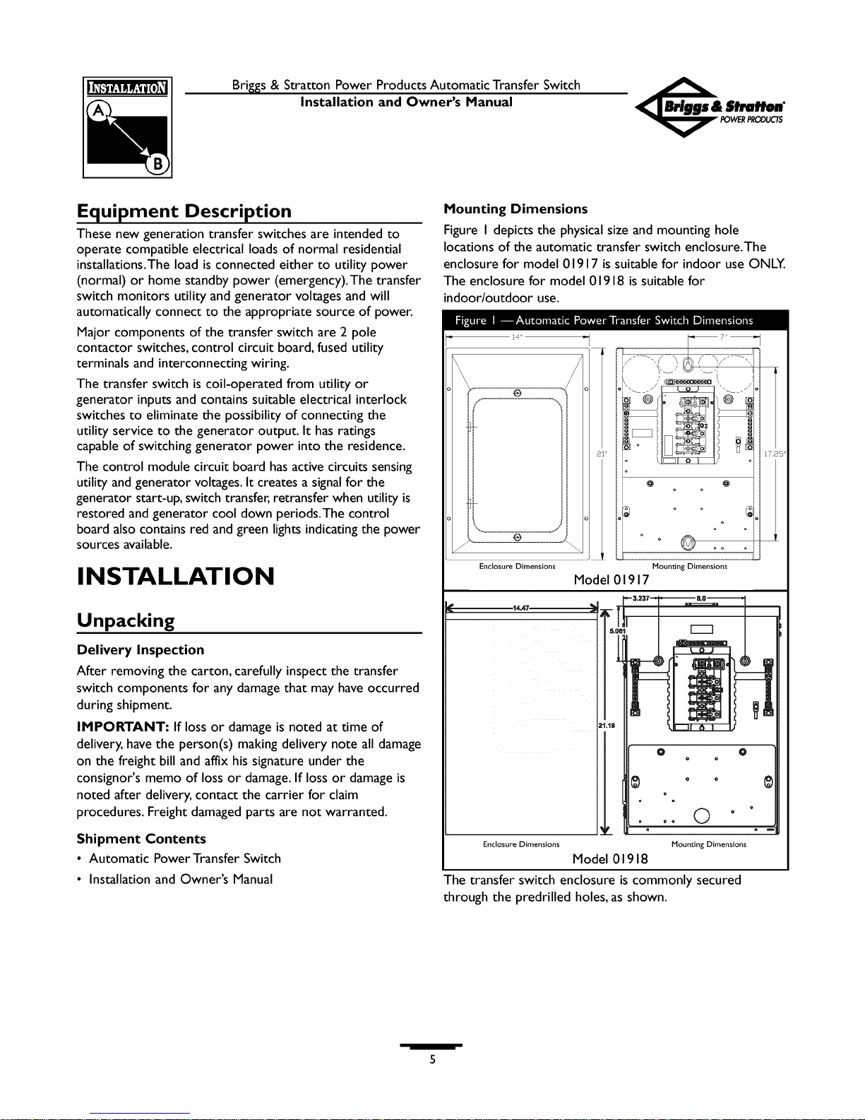
Mounting Dimensions
Figure I depicts the physical size and mounting hole
locations of the automatic transfer switch enclosure.The
enclosure for model 01917 is suitable for indoor use ONLY.
The enclosure for model 01918 is suitable for
indoor/outdoor use.
®
®
Enclosure Dimensions Mounting Dimensions
Model 01917
Unpacking
Delivery Inspection
After removing the carton, carefully inspect the transfer
switch components for any damage that may have occurred
during shipment.
IMPORTANT: If loss or damage is noted at time of
delivery, have the person(s) making delivery note all damage
on the freight bill and affix his signature under the
consignor's memo of loss or damage. If loss or damage is
noted after delivery, contact the carrier for claim
procedures. Freight damaged parts are not warranted.
Shipment Contents
• Automatic Power Transfer Switch
• Installation and Owner's Manual
Enclosure Dimensions Mounting Dimensions
Model 01918
The transfer switch enclosure is commonly secured
through the predrilled holes, as shown.
Bri_s&StrattonPowerProductsAutomaticTransferSwitch
Installation and Owner's Manual
ESSENTIAL CIRCUIT
ISOLATION
Essential electrical loads are loads that will be powered by
the Home Generator System. Essential loads are grouped
together and wired into the transfer switch.
TO THE INSTALLER: Consult with Home
Generator System owner(s) to discuss their
"Selection of Essential Circuits", described in the
owner's manual.
To Utility Power
I........
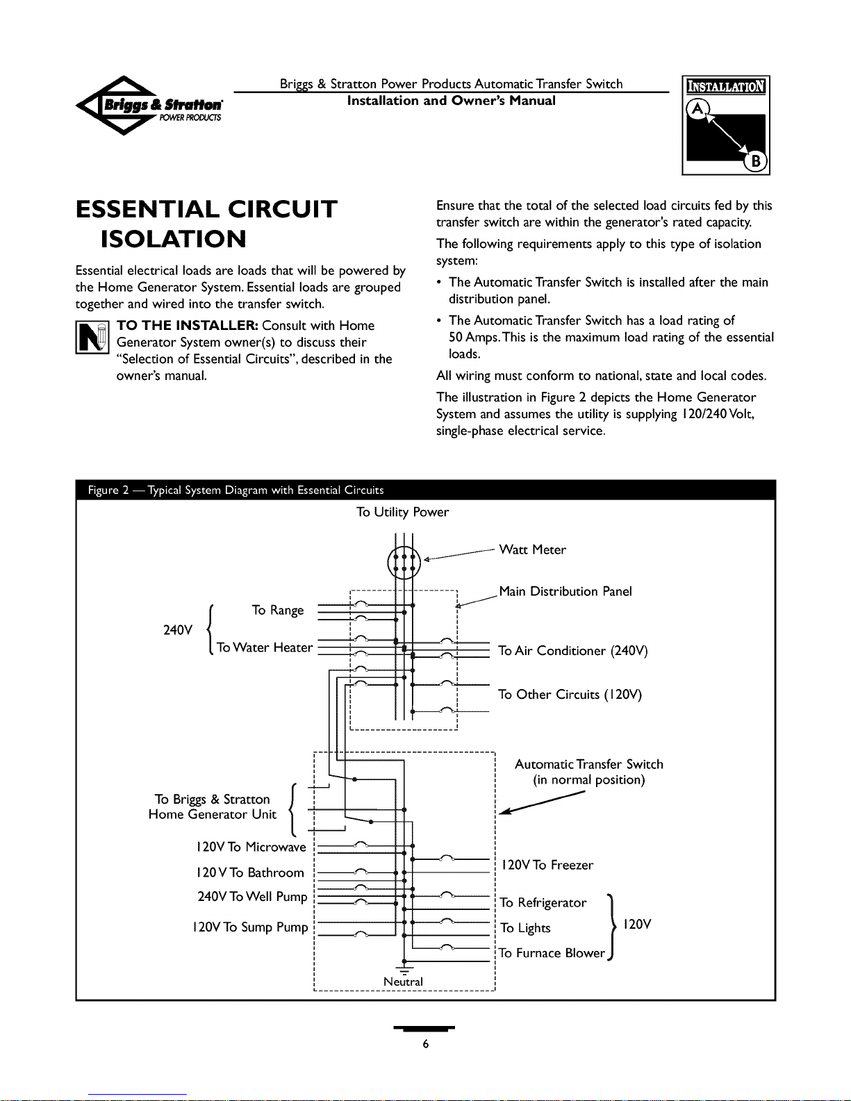
Ensure that the total of the selected load circuits fed by this
transfer switch are within the generator's rated capacity.
The following requirements apply to this type of isolation
system:
• The Automatic Transfer Switch is installed after the main
distribution panel.
• The Automatic Transfer Switch has a load rating of
50 Amps.This is the maximum load rating of the essential
loads.
All wiring must conform to national, state and local codes.
The illustration in Figure 2 depicts the Home Generator
System and assumes the utility is supplying 120/240Volt,
single-phase electrical service.
,_________I Watt Meter
......... ., i Main Distribution Panel
240V ,__.__ _--
To Range --'_-----
To Water Heater _____
.....................
i'--
i
i
i
To griggs & Stratton 1
I
Home Generator Unit ,,
120V To Microwave '
120VTo Bathroom
240V To Well Pump ,
120VTo Sump Pump
L ..................................
Neutral
To Air Conditioner (240V)
To Other Circuits (120V)
,,
i
Automatic Transfer Switch
(in normal position)
120VTo Freezer
To Lights
To Refrigerator }
To Furnace Blower
-2"
120V

l_ I Brig, s & Stratton Power Products Automatic Transfer Switch
Installation and Owner's Manual
Mounting Guidelines
The Model 01917 Automatic Transfer Switch is enclosed in
a NEMAType I enclosure suitable for indoor use only.
The Model 01918 Automatic Transfer Switch is enclosed in
a NEMAType 3R enclosure suitable for indoor/outdoor
use.
Guidelines for mounting the Automatic Transfer Switch
include:
• Model 01918 Automatic Transfer Switch must be installed
with minimum NEMA 3R hardware for conduit
connections.
• Install the switch on a firm, sturdy supporting structure.
• To prevent switch contact distortion, level and plumb the
enclosure.This can be done by placing washers between I.
the switch enclosure and the mounting surface.
• NEVER install the switch where any corrosive substance
might drip onto the enclosure.
• Protect the switch at all times against excessive moisture,
dust, dirt, lint, construction grit and corrosive vapors. 2.
The typical installation of the Automatic Power Transfer
Switch is depicted in Figure 3. Discuss layout 3.
suggestions/changes with the owner before beginning the
system installation process. 4.
Main
Distribution
Panel
Automatic
Transfer Switch
Power Wiring Interconnections
All wiring must be the proper size, properly supported, of
approved insulation qualities, and protected by NEC
approved conduit.
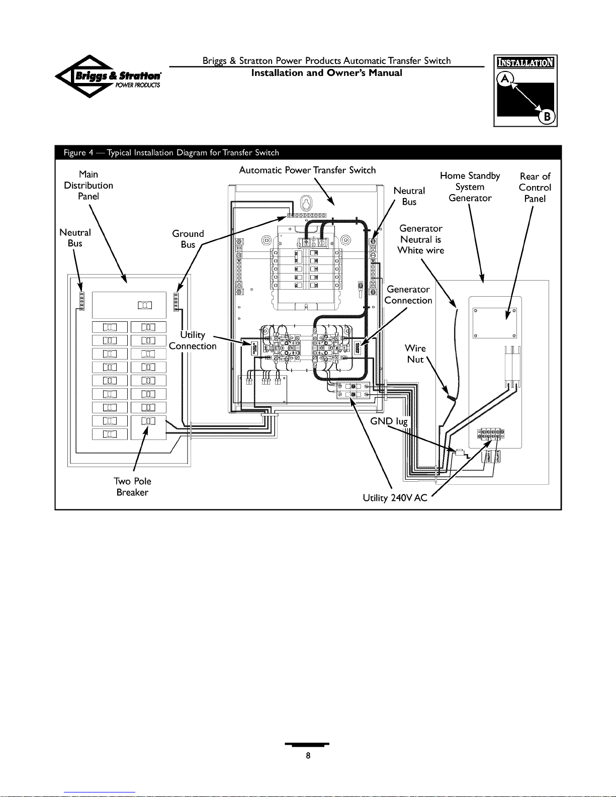
Complete the following connections between the
generator, transfer switch and main distribution panel
(Figure 4, on next page).
CAUTION
Failure to follow above warning could cause damage and/or
malfunction of equipment.
Connect utility power supply leads from a two pole
breaker installed in the main distribution panel to
transfer switch terminals marked "UTILITY
CONNECTION". Use a 50 Amp circuit breaker.
Ensure breaker is turned OFF.
Connect main distribution panel ground to the transfer
switch "GND" bus.
Connect main distribution panel neutral lead to
transfer switch "NEUTRAL" terminal.
Connect generator power supply leads from the
generator's control panel to transfer switch terminals
marked "GENERATOR CONNECTION".
.
Connect generator Neutral from the control panel to
the transfer switch "NEUTRAL" terminal.
6.
Connect generator"GND" from the control panel to
the transfer switch "GND" terminal.
7.
Connect generator utility 240V terminals to transfer
switch utility 240V terminals.
8.
Tighten all wire connections/fasteners to proper
torque.
Bri_s&StrattonPowerProductsAutomaticTransferSwitch 1_1
Installation and Owner's Manual
Main
Distribution
Panel
Neutral Ground
Bus Bus
Utility
[_ [_ Connection
Automatic Power Transfer Switch
Neutral
Bus
Generator
Neutral is
White wire
Generator
Connection
Wire i
Home Standby
System
Generator
/
J
Rearof
Control
Panel
/
Two Pole
Breaker
Utility 240V AC
Brig,s& StrattonPowerProductsAutomaticTransferSwitch
Installation and Owner's Manual
SYSTEM OPERATION
To select automatic transfer operation, do the following:
I. Set circuit breaker that sends utility power to transfer
switch to "On" position.
2. Set generator's main circuit breaker to its "On"
position.
3. Install 15Amp fuse in control panel on generator.
4. Set AUTO/OFF/MANUAL switch on generator to
"AUTO" position.
The system will now be in automatic operation mode.
TESTING THE
AUTOMATIC TRANSFER
SWITCH
Turn the circuit breaker feeding the transfer switch, to the
"Off' position.The automatic sequence will follow.To go
back to utility power, turn the circuit breaker to the "On"
position.
Automatic Sequence
Utility Fail
Utility voltage sensor senseswhen utility voltage isbelow
70 percent of nominal. Enginestart sequence is initiated
after 6 second time delay.
Engine Warm-Up
Time delay to allow for engine warm-up before transfer
fixed at 20 seconds or 50 seconds with optional cold
weather package.
Transfer
Transfers from utility to standby supply occurs after
standby voltage is above set levels. Minimum engine run
time is 4 minutes after transfer.
Utility Pickup
Voltagepickup level is80 percent of nominal voltage.
Retransfer
Retransfer from standby to utility supply 10 seconds after
utility voltage supply is above pickup level.
Engine Cool Down
Engine will run for 60 seconds after retransfer.
Specifications
UL® 1008 Listed Transfer Switch
Model 01917
Enclosure ................... NEMA I
Maximum Load/Circuit:
from Load Center .......... 50Amps
RatedAC Voltage ............. 250 Volts
Poles ...................... 2
Frequency .................. 50/60 Hz
Fault Current Rating .......... 5,000 RMS Symmetrical
Amperes
Weight ..................... 27 Ibs.
Model 01918
Enclosure................... NEMA 3R
Maximum Load/Circuit:
from Load Center .......... 50 Amps
RatedAC Voltage ............. 250 Volts
Poles ...................... 2
Frequency .................. 50/60 Hz
Fault Current Rating .......... 5,000 RMS Symmetrical
Amperes
Weight ..................... 34 Ibs.
When Calling the Factory
Before contacting Briggs and Stratton Power Products
regarding service or repair of this transfer switch, obtain
the Model Number and Serial Number from the unit data
decal located on or inside the case.
To contact Briggsand Stratton Power Products call
1-800-743-4115,between 8:00AM and 5:00 PM CT.

NOTES
Brig, s & Stratton Power Products Automatic Transfer Switch
Installation and Owner's Manual
10
Brig,s& StrattonPowerProductsAutomaticTransferSwitch
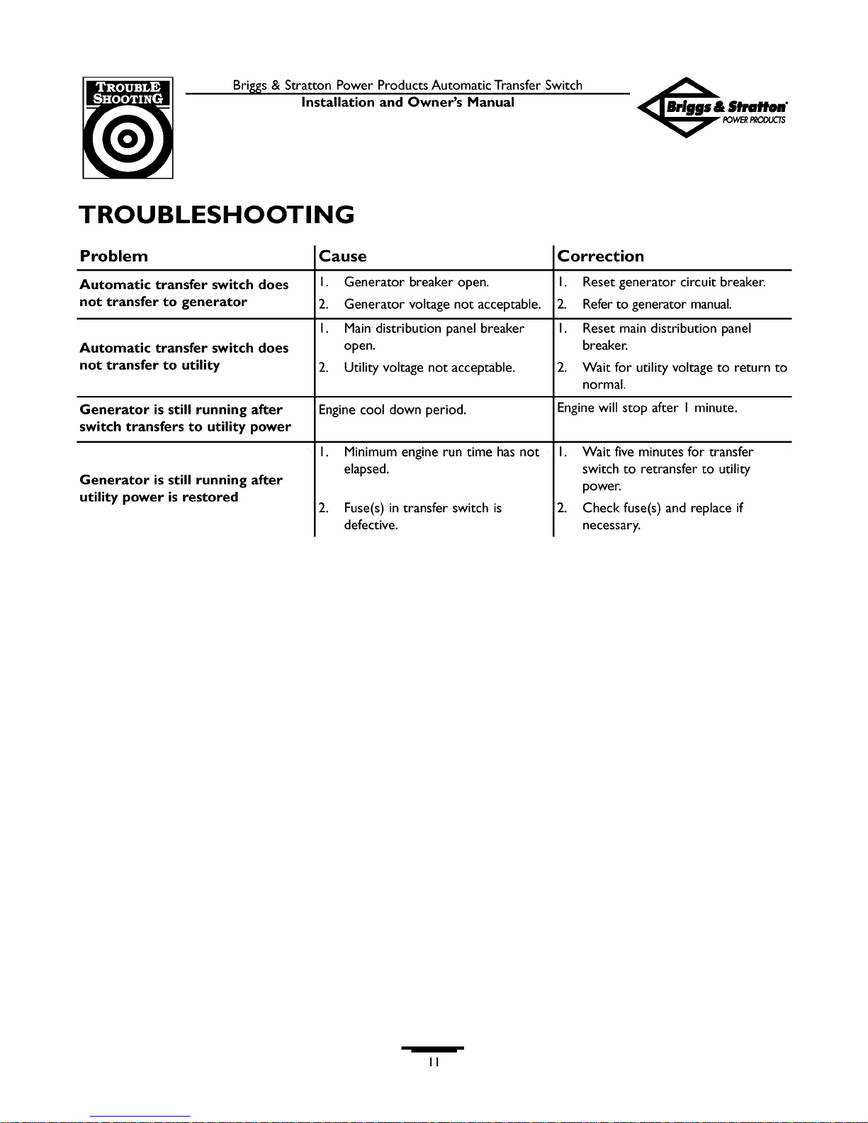
TROUBLESHOOTING
Installation and Owner's Manual
Problem Cause
Automatic transfer switch does I.
not transfer to generator 2.
Automatic transfer switch does
not transfer to utility .
Generator is still running after Engine cool down period.
switch transfers to utility power
Generator breaker open.
Generator voltage not acceptable.
I.
Maindistribution panel breaker
open.
Utility voltage not acceptable.
I. Minimum engine run time hasnot
elapsed.
Generator is still running after
utility power is restored
2. Fuse(s) in transfer switch is
defective.
Correction
I. Reset generator circuit breaker.
2. Refer to generator manual.
I. Reset main distribution panel
breaker.
2. Wait for utility voltage to return to
normal.
Engine will stop after I minute.
I.
Wait five minutes for transfer
switch to retransfer to utility
power.
.
Check fuse(s) and replace if
necessary.
II
Brig,s& StrattonPowerProductsAutomaticTransferSwitch
Installation and Owner's Manual
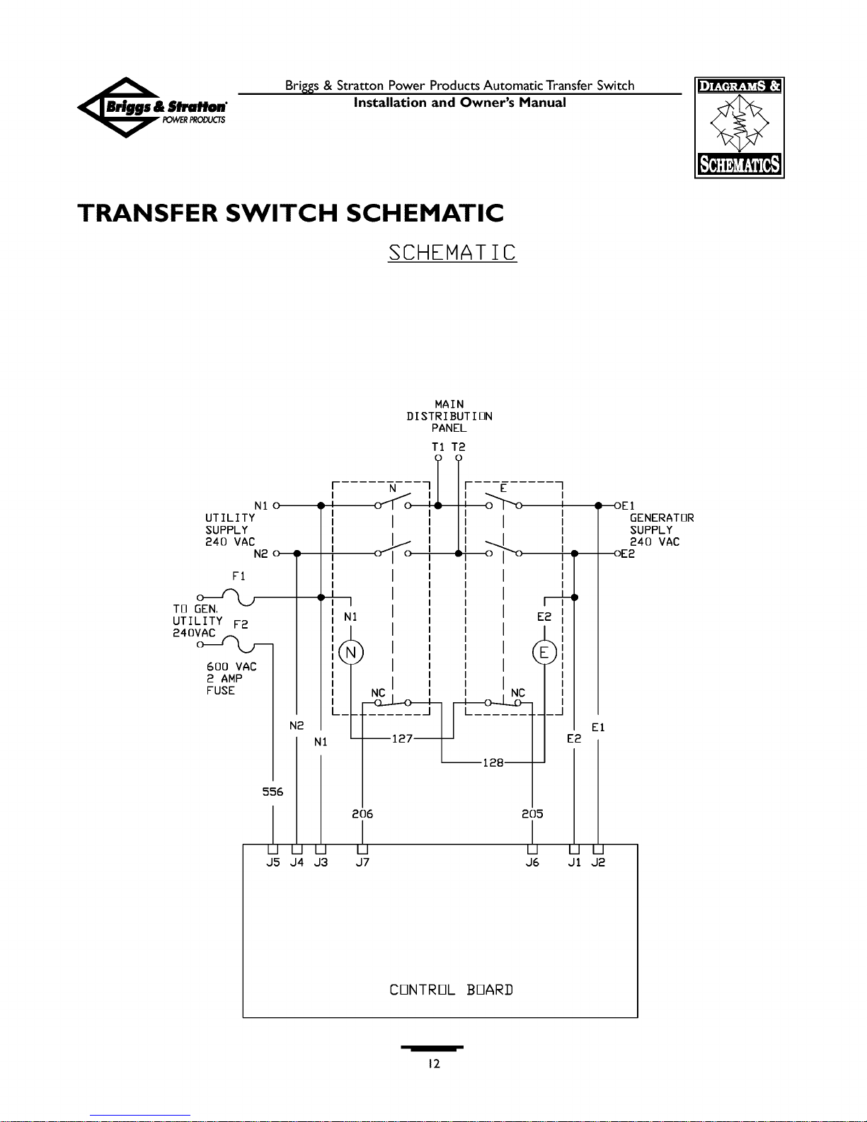
TRANSFER SWITCH SCHEMATIC
SCHEMATIC
MAIN
DISTRIBUTION
PANEL
UTILITY
SUPPLY
240 VAC
NI o
U [J U
J5 J4 J3
[ N
I j
i,I O / O
I
I
I
I
206
U
J7
E
D OE1
GENERATOR
SUPPLY
240 VAC
205
U U [J
J6 J1 J2
CONTROL BOAR]]
12
 Loading...